EP4119956A1 - Arc detection device, indoor power line system, solar power generation system, and storage battery system - Google Patents
Arc detection device, indoor power line system, solar power generation system, and storage battery system Download PDFInfo
- Publication number
- EP4119956A1 EP4119956A1 EP21767146.0A EP21767146A EP4119956A1 EP 4119956 A1 EP4119956 A1 EP 4119956A1 EP 21767146 A EP21767146 A EP 21767146A EP 4119956 A1 EP4119956 A1 EP 4119956A1
- Authority
- EP
- European Patent Office
- Prior art keywords
- power
- converter
- converters
- arc
- electric
- Prior art date
- Legal status (The legal status is an assumption and is not a legal conclusion. Google has not performed a legal analysis and makes no representation as to the accuracy of the status listed.)
- Granted
Links
Images


Classifications
-
- G—PHYSICS
- G01—MEASURING; TESTING
- G01R—MEASURING ELECTRIC VARIABLES; MEASURING MAGNETIC VARIABLES
- G01R31/00—Arrangements for testing electric properties; Arrangements for locating electric faults; Arrangements for electrical testing characterised by what is being tested not provided for elsewhere
- G01R31/08—Locating faults in cables, transmission lines, or networks
- G01R31/081—Locating faults in cables, transmission lines, or networks according to type of conductors
- G01R31/083—Locating faults in cables, transmission lines, or networks according to type of conductors in cables, e.g. underground
-
- H—ELECTRICITY
- H02—GENERATION; CONVERSION OR DISTRIBUTION OF ELECTRIC POWER
- H02H—EMERGENCY PROTECTIVE CIRCUIT ARRANGEMENTS
- H02H1/00—Details of emergency protective circuit arrangements
- H02H1/0007—Details of emergency protective circuit arrangements concerning the detecting means
- H02H1/0015—Using arc detectors
-
- G—PHYSICS
- G01—MEASURING; TESTING
- G01R—MEASURING ELECTRIC VARIABLES; MEASURING MAGNETIC VARIABLES
- G01R15/00—Details of measuring arrangements of the types provided for in groups G01R17/00 - G01R29/00, G01R33/00 - G01R33/26 or G01R35/00
- G01R15/14—Adaptations providing voltage or current isolation, e.g. for high-voltage or high-current networks
- G01R15/20—Adaptations providing voltage or current isolation, e.g. for high-voltage or high-current networks using galvano-magnetic devices, e.g. Hall-effect devices, i.e. measuring a magnetic field via the interaction between a current and a magnetic field, e.g. magneto resistive or Hall effect devices
- G01R15/202—Adaptations providing voltage or current isolation, e.g. for high-voltage or high-current networks using galvano-magnetic devices, e.g. Hall-effect devices, i.e. measuring a magnetic field via the interaction between a current and a magnetic field, e.g. magneto resistive or Hall effect devices using Hall-effect devices
-
- G—PHYSICS
- G01—MEASURING; TESTING
- G01R—MEASURING ELECTRIC VARIABLES; MEASURING MAGNETIC VARIABLES
- G01R31/00—Arrangements for testing electric properties; Arrangements for locating electric faults; Arrangements for electrical testing characterised by what is being tested not provided for elsewhere
- G01R31/12—Testing dielectric strength or breakdown voltage ; Testing or monitoring effectiveness or level of insulation, e.g. of a cable or of an apparatus, for example using partial discharge measurements; Electrostatic testing
- G01R31/1227—Testing dielectric strength or breakdown voltage ; Testing or monitoring effectiveness or level of insulation, e.g. of a cable or of an apparatus, for example using partial discharge measurements; Electrostatic testing of components, parts or materials
- G01R31/1263—Testing dielectric strength or breakdown voltage ; Testing or monitoring effectiveness or level of insulation, e.g. of a cable or of an apparatus, for example using partial discharge measurements; Electrostatic testing of components, parts or materials of solid or fluid materials, e.g. insulation films, bulk material; of semiconductors or LV electronic components or parts; of cable, line or wire insulation
- G01R31/1272—Testing dielectric strength or breakdown voltage ; Testing or monitoring effectiveness or level of insulation, e.g. of a cable or of an apparatus, for example using partial discharge measurements; Electrostatic testing of components, parts or materials of solid or fluid materials, e.g. insulation films, bulk material; of semiconductors or LV electronic components or parts; of cable, line or wire insulation of cable, line or wire insulation, e.g. using partial discharge measurements
-
- G—PHYSICS
- G01—MEASURING; TESTING
- G01R—MEASURING ELECTRIC VARIABLES; MEASURING MAGNETIC VARIABLES
- G01R31/00—Arrangements for testing electric properties; Arrangements for locating electric faults; Arrangements for electrical testing characterised by what is being tested not provided for elsewhere
- G01R31/40—Testing power supplies
-
- G—PHYSICS
- G01—MEASURING; TESTING
- G01R—MEASURING ELECTRIC VARIABLES; MEASURING MAGNETIC VARIABLES
- G01R19/00—Arrangements for measuring currents or voltages or for indicating presence or sign thereof
- G01R19/10—Measuring sum, difference or ratio
Definitions
- the present invention relates to arc detection devices, indoor power line systems, solar power generation systems, and storage battery systems.
- the present invention provides an arc detection device, etc., capable of easily detecting electric arcs occurring in a plurality of power lines.
- An arc detection device is an arc detection device in a system including one or more power sources, a plurality of converters that adjust voltages of the one or more power sources, and a plurality of load devices.
- the one or more power sources and the plurality of converters are connected to each other by a plurality of power lines.
- the plurality of converters and the plurality of load devices are connected to each other by a plurality of power lines.
- the arc detection device includes: an electric current detector that includes a magnetic core through which two or more power lines included in the plurality of power lines extend, and detects combined currents flowing through the two or more power lines according to a magnetic field produced at the magnetic core; and an arc determiner that determines, based on the combined currents detected by the electric current detector, whether an electric arc has occurred.
- One or more converters included in the plurality of converters are connected to the one or more power sources.
- One or more converters included in the plurality of converters are connected to each of the plurality of load devices.
- An indoor power line system includes: the above-described arc detection device.
- One power source included in the one or more power sources includes a system power supply.
- the plurality of converters include AC/DC converters.
- a solar power generation system includes: the above-described arc detection device. At least one power source included in the one or more power sources includes a solar cell. Another power source included in the one or more power sources includes a system power supply. One load device included in the plurality of load devices includes a DC/AC converter connected to the system power supply.
- a storage battery system includes: the above-described arc detection device; a storage battery that operates as at least one power source included in the one or more power sources or at least one load device included in the plurality of load devices; and a system power supply that operates as at least one power source included in the one or more power sources or at least one load device included in the plurality of load device.
- the system power supply operates as a power source
- a converter connected to the system power supply operates as an AC/DC converter
- the storage battery and a converter connected to the storage battery each operate as a load device.
- the storage battery operates as a power source
- a converter connected to the storage battery operates as a DC/DC converter
- the system power supply and a converter connected to the system power supply each operate as a load device.
- electric arcs occurring in the plurality of power lines can be easily detected.
- FIG. 1 is a configuration diagram illustrating one example of system 1a according to Embodiment 1.
- System 1a is a solar power generation system as well as being a storage battery system (for example, a system including a photovoltaic function and a power storage function).
- System 1a includes one or more power sources, a plurality of converters that adjust the voltages of the one or more power sources, and a plurality of load devices. Furthermore, system 1a includes arc detection device 10a.
- solar cell 62, system power supply 48, and storage batteries 51, 52 are illustrated as the one or more power sources.
- DC/DC converters 41, 42, and 43 and inverter 44 are illustrated as the plurality of converters.
- System power supply 48, inverter 44, and storage batteries 51, 52 can be the load devices depending on situation.
- One or more converters included in the plurality of converters are connected to the one or more power sources, and one or more converters included in the plurality of converters are connected to each of the plurality of load devices.
- DC/DC converter 41 is connected to solar cell 62, which operates as a power source
- inverter 44 is connected to system power supply 48, which operates as a power source or a load device
- DC/DC converter 42 is connected to storage battery 51, which operates as a power source or a load device
- DC/DC converter 43 is connected to storage battery 52, which operates as a power source or a load device.
- the one or more power sources and the plurality of converters are connected by a plurality of power lines, and the plurality of converters and the plurality of load devices are connected by a plurality of power lines.
- solar cell 62 and DC/DC converter 41 are connected by the plurality of power lines
- system power supply 48 and inverter 44 are connected by the plurality of power lines
- storage battery 51 and DC/DC converter 42 are connected by the plurality of power lines
- storage battery 52 and DC/DC converter 43 are connected by the plurality of power lines
- DC/DC converter 41, DC/DC converter 42, DC/DC converter 43, and inverter 44 are connected by the plurality of power lines.
- solar cell 62 and DC/DC converter 41 are connected by power lines 140a, 140b
- system power supply 48 and inverter 44 are connected by power lines 150a, 150b
- storage battery 51 and DC/DC converter 42 are connected by power lines 120a, 120b
- storage battery 52 and DC/DC converter 43 are connected by power lines 130a, 130b
- DC/DC converter 41, DC/DC converter 42, DC/DC converter 43, and inverter 44 are connected by power lines 110a, 110b.
- Solar cell 62 is a power source that generates direct-current power by generating electric power using sunlight.
- the direct-current power generated by solar cell 62 is supplied to DC/DC converter 41 and then supplied to one load device (a load device including inverter 44 (specifically a DC/AC converter) connected to system power supply 48) included in the plurality of load devices.
- Solar cell 62 includes a positive electrode and a negative electrode; power line 140a is connected to the positive electrode, and power line 140b is connected to the negative electrode.
- System power supply 48 supplies alternating-current power generated at a power station or the like. Note that as mentioned above, system power supply 48 can be a load device to which electric power is supplied, depending on situation.
- Storage batteries 51, 52 each operate as at least one power source included in the one or more power sources and at least one load device included in the plurality of load devices.
- system power supply 48 operates as a power source
- the converter (specifically, inverter 44) connected to system power supply 48 operates as an AC/DC converter
- storage batteries 51, 52 and the converters (specifically, DC/DC converters 42, 43) connected to storage batteries 51, 52 each operate as a load device.
- storage batteries 51, 52 each operate as a power source
- the converters connected to storage batteries 51, 52 operate as DC/DC converters 42, 43
- system power supply 48 and the converter (specifically inverter 44) connected to system power supply 48 each operate as a load device.
- DC/DC converter 41 increases or decrease the voltage of the direct-current power supplied thereto from solar cell 62 and outputs the direct-current power to DC/DC converters 42, 43 and inverter 44.
- DC/DC converter 41 includes a positive electrode and a negative electrode; power line 110a is connected to the positive electrode, and power line 110b is connected to the negative electrode.
- DC/DC converter 42 increases or decreases the voltage of the direct-current power supplied thereto from DC/DC converter 41 or inverter 44 and outputs the direct-current power to storage battery 51. Furthermore, DC/DC converter 42 increases or decreases the voltage of the direct-current power supplied thereto from storage battery 51 and outputs the direct-current power to DC/DC converter 43 or inverter 44.
- DC/DC converter 42 includes a positive electrode and a negative electrode; power line 120a is connected to the positive electrode, and power line 120b is connected to the negative electrode.
- DC/DC converter 43 increases or decreases the voltage of the direct-current power supplied thereto from DC/DC converter 41 or inverter 44 and outputs the direct-current power to storage battery 52. Furthermore, DC/DC converter 43 increases or decreases the voltage of the direct-current power supplied thereto from storage battery 52 and outputs the direct-current power to DC/DC converter 42 or inverter 44.
- DC/DC converter 43 includes a positive electrode and a negative electrode; power line 130a is connected to the positive electrode, and power line 130b is connected to the negative electrode.
- Power lines 110a, 120a are one example of two or more power lines extending through magnetic core 21a to be described later.
- Inverter 44 operates as a DC/AC converter that converts the direct-current power supplied thereto from DC/DC converters 41, 42, 43 into alternating-current power and outputs the alternating-current power. Furthermore, inverter 44 operates as an AC/DC converter that converts the alternating-current power supplied thereto from system power supply 48 into direct-current power and supplies the direct-current power to DC/DC converters 42, 43. For example, inverter 44 converts the direct-current power into alternating-current power having a frequency of 50 Hz or 60 Hz. The alternating-current power is used in home appliances and the like. Alternating currents flow through power lines 150a, 150b connecting inverter 44 and system power supply 48.
- the two or more power lines extending through magnetic core 21a to be described later are, for example, the power line connected to one input/output terminal of the first converter included in the plurality of converters and the power line connected to the other input/output terminal of the first converter included in the plurality of converters.
- the first converter is DC/DC converter 42
- the two or more power lines extending through magnetic core 21a to be described later are power line 110a connected to one input/output terminal of DC/DC converter 42 and power line 120a connected to the other input/output terminal of DC/DC converter 42.
- Power line 110a connected to one input/output terminal of DC/DC converter 42 is a branch power line that is divided as a plurality of branch paths 111a, 111b, 111c, 111d.
- the connection point between the plurality of branch paths 111a, 111b, 111c, 111d in power line 110a is denoted as branch point N.
- the path connecting branch point N and DC/DC converter 41 is branch path 111a
- the path connecting branch point N and DC/DC converter 43 is branch path 111b
- the path connecting branch point N and inverter 44 is branch path 111c
- the path connecting branch point N and DC/DC converter 42 is branch path 111d.
- Branch path 111d extends through magnetic core 21a to be described later.
- electric currents flowing through power line 110a connected to one input/output terminal of DC/DC converter 42 and power line 120a connected to the other input/output terminal of DC/DC converter 42 are direct currents and therefore, there is a possibility that an electric arc may occur in each of power lines 110a, 120a. If the arc detection means is provided in power line 110a, an electric arc that has occurred in power line 110a can be detected, but high-frequency components resulting from an electric arc that has occurred in power line 120a are blocked by a capacitor and the like that are present in DC/DC converter 42; thus, it is difficult to detect the electric arc that has occurred in power line 120a.
- the arc detection means is provided in power line 120a, an electric arc that has occurred in power line 120a can be detected, but it is likewise difficult to detect an electric arc that has occurred in power line 110a. If the arc detection means is provided in both power lines 110a, 120a, an electric arc that has occurred in power line 110a and an electric arc that has occurred in power line 120a can be detected, but the size and cost of the system would increase.
- arc detection device 10a is used in order to easily detect electric arcs occurring in two or more power lines (in this example, for example, power lines 110a, 120a) included in the plurality of power lines in system 1a.
- Arc detection device 10a includes electric current detector 20a and arc determiner 30a.
- Electric current detector 20a includes magnetic core 21a through which power lines 110a, 120a extend, and detects combined currents flowing through power lines 110a, 120a according to the magnetic field produced at magnetic core 21a.
- electric current detector 20a includes magnetic core 21a through which power line 120a and branch path 111d included in power line 110a and connecting branch point N and one input/output terminal of DC/DC converter 42 extend, and detects combined currents flowing in branch path 111d and power line 120a according to the magnetic field produced at magnetic core 21a.
- power line 110a connected to one input/output terminal of DC/DC converter 42 and power line 120a connected to the other input/output terminal of DC/DC converter 42 are bound together at magnetic core 21a and extend through magnetic core 21a, as illustrated in FIG.
- the two or more power lines include a power line through which, at the magnetic core, the direct current flows in the direction opposite to the direction of the direct currents flowing through the other power lines.
- power lines 110a, 120a extend through magnetic core 21a in such a manner that the direction of the direct current flowing through power line 110a and the direction of the direct current flowing through power line 120a are opposite to each other at magnetic core 21a.
- Magnetic core 21a is in the form of a loop (in this example, the form of a circular ring) through which the power lines can extend; electric currents flowing through the power lines extending through the hole of magnetic core 21a produce, at the core, a magnetic field that corresponds to said electric currents.
- magnetic core 21a is not limited to being in the form of a circular ring and may be in the form of a rectangular loop or the like.
- electric current detector 20a includes, for example, a Hall element (not illustrated in the drawings) that detects the magnetic field produced at magnetic core 21a and generates a voltage corresponding to the magnetic field produced at magnetic core 21a.
- the voltage generated by the Hall element is input to arc determiner 30a as a signal indicating the magnetic field produced at magnetic core 21a, that is, the electric currents flowing through power lines 110a, 120a extending through the magnetic core 21a.
- Arc determiner 30a is, for example, a microcomputer.
- the microcomputer is a semiconductor integrated circuit or the like including read-only memory (ROM) and random-access memory (RAM) each having a program stored therein, a processor (a central processing unit) (CPU) that executes the program, a timer, an A/D converter, a D/A converter, and the like.
- arc determiner 30a may be provided as hardware using a dedicated electronic circuit including an A/D converter, a logical circuit, a gate array, a D/A converter, and the like, or an amplifier and a filter circuit, for example.
- Arc determiner 30a determines, on the basis of the combined currents detected by electric current detector 20a, whether an electric arc has occurred. For example, arc determiner 30a determines, by performing a frequency analysis on the combined currents detected by electric current detector 20a, whether an electric arc has occurred in power line 110a or 120a. An electric current resulting from the occurrence of an electric arc includes frequency components attributed to the electric arc; thus, by detecting said frequency components, it is possible to determine whether an electric arc has occurred. When arc determiner 30a determines that an electric arc has occurred, it is clear that the electric arc has occurred in one of power lines 110a, 120a. This means that electric arcs in the two or more power lines (in this example, power lines 110a, 120a) can be detected using only one electric current detector 20a (specifically, magnetic core 21a).
- the two or more power lines extending through magnetic core 21a may include a power line other than power line 110a (specifically, branch path 111d) and power line 120a.
- the two or more power lines may further include at least one of power line 130a or 130b and power line 140a or 140b.
- at least one of power line 130a or 130b and power line 140a or 140b may also extend through magnetic core 21a.
- arc detection device 10a is used in system 1a including one or more power sources (for example, a power source selected from solar cell 62, system power supply 48, and storage batteries 51, 52), a plurality of converters (for example, a plurality of converters selected from DC/DC converters 41, 42, 43, and inverter 44) that adjust the voltages of the one or more power sources, and a plurality of load devices (for example, a plurality of load devices selected from storage batteries 51, 52, system power supply 48, and inverter 44).
- power sources for example, a power source selected from solar cell 62, system power supply 48, and storage batteries 51, 52
- a plurality of converters for example, a plurality of converters selected from DC/DC converters 41, 42, 43, and inverter 44
- load devices for example, a plurality of load devices selected from storage batteries 51, 52, system power supply 48, and inverter 44.
- Arc detection device 10a includes: electric current detector 20a which includes magnetic core 21a through which two or more power lines (for example, power lines 110a, 120a) included in the plurality of power lines extend, and detects combined currents flowing through the two or more power lines according to the magnetic field produced at magnetic core 21a; and arc determiner 30a which determines, on the basis of the combined currents detected by electric current detector 20a, whether an electric arc has occurred.
- electric current detector 20a which includes magnetic core 21a through which two or more power lines (for example, power lines 110a, 120a) included in the plurality of power lines extend, and detects combined currents flowing through the two or more power lines according to the magnetic field produced at magnetic core 21a
- arc determiner 30a which determines, on the basis of the combined currents detected by electric current detector 20a, whether an electric arc has occurred.
- One or more converters included in the plurality of converters are connected to one or more power sources, and one or more converters included in the plurality of converters are connected to each
- the two or more power lines (for example, power lines 110a, 120a) are bound together and extend through one magnetic core 21a; thus, no matter in which power line included in the two or more power lines an electric arc occurs, the electric arc can be detected.
- the arc detection means is not provided in each of the two or more power lines, electric arcs occurring in the two or more power lines can be detected.
- DC/DC converters 41, 42, 43 and inverter 44 can be stopped or a circuit breaker (not illustrated in the drawings) or the like provided in each power line can be operated to shut off an electric current flowing through the power line, for example, on the basis of the result of the detection.
- the two or more power lines may be power line 110a connected to one input/output terminal of the first converter (for example, DC/DC converter 42) included in the plurality of converters and power line 120a connected to the other input/output terminal of the first converter (for example, DC/DC converter 42) included in the plurality of converters.
- the first converter for example, DC/DC converter 42
- the second input/output terminal of the first converter for example, DC/DC converter 42
- the two or more power lines may include power lines through which electric currents flow in the opposite directions at magnetic core 21a.
- the two or more power lines are provided extending through magnetic core 21a so as to include a power line through which at magnetic core 21a, the direct current flows in the direction opposite to the direction of the direct currents flowing through the other power lines, and thus the magnetic fields produced by the direct currents flowing through the power lines through which the direct currents flow in the opposite directions can be canceled out, preventing the magnetic saturation.
- a solar power generation system (for example, system 1a) according to the present embodiment includes arc detection device 10a. At least one power source included in the one or more power source is solar cell 62. Another power source included in the one or more power sources is system power supply 48. One load device included in the plurality of load devices is a DC/AC converter (for example, inverter 44) connected to system power supply 48.
- DC/AC converter for example, inverter 44
- a storage battery system (for example, system 1a) according to the present embodiment includes: arc detection device 10a; storage batteries 51, 52 each of which operates as at least one power source included in the one or more power sources or at least one load device included in the plurality of load devices; and system power supply 48 which operates as at least one power source included in the one or more power sources or at least one load device included in the plurality of load devices.
- system power supply 48 operates as a power source
- the converter for example, inverter 44
- storage batteries 51, 52 and the converters for example, DC/DC converters 42, 43
- storage batteries 51, 52 each operate as a power source
- the converters connected to storage batteries 51, 52 operate as DC/DC converters 42, 43
- system power supply 48 and the converter (for example, inverter 44) connected to system power supply 48 each operate as a load device.
- At least one power source included in the one or more power sources may be solar cell 62.
- Embodiment 1 has thus far described an example in which arc detection device 10a includes one electric current detector 20a. Variation of Embodiment 1 will describe an example in which the arc detection device includes a plurality of (for example, two) electric current detectors.
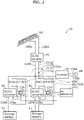
- FIG. 2 is a configuration diagram illustrating one example of system 1b according to a variation of Embodiment 1.
- System 1b is different from system 1a according to Embodiment 1 in that arc detection device 10b is included instead of arc detection device 10a.
- the other features are the same as those in Embodiment 1 and as such, description thereof will be omitted.
- Arc detection device 10b includes electric current detectors 20a, 20b and arc determiner 30b.
- Electric current detector 20a is the same as that described in Embodiment 1 and as such, description thereof will be omitted. Note that in the variation of Embodiment 1, signals indicating electric currents flowing through power lines 110a, 120a extending through magnetic core 21a in electric current detector 20a are input to arc determiner 30b.
- Electric current detector 20b includes magnetic core 21b through which power lines 110a, 130a extend, and detects electric currents flowing through power lines 110a, 130a according to the magnetic field produced at magnetic core 21b.
- electric current detector 20b includes magnetic core 21b through which branch path 111b in power line 110a connecting branch point N and DC/DC converter 43 and power line 130a connected to the other input/output terminal of DC/DC converter 43 extend, and detects electric currents flowing in branch path 111b and power line 130a according to the magnetic field produced at magnetic core 21b.
- power line 110a connected to one input/output terminal of DC/DC converter 43 and power line 130a connected to the other input/output terminal of DC/DC converter 43 are bound together at magnetic core 21b and extend through magnetic core 21b, as illustrated in FIG. 2 .
- power lines 110a, 130a include a power line through which, at magnetic core 21b, the direct current flows in the direction opposite to the direction of the direct currents flowing through the other power lines.
- power lines 110a, 130a extend through magnetic core 21b in such a manner that the direction of the direct current flowing through power line 110a and the direction of the direct current flowing through power line 130a are opposite to each other at magnetic core 21b.
- Magnetic core 21b is in the form of a loop (in this example, the form of a circular ring) through which the power lines can extend; electric currents flowing through the power lines extending through the hole of magnetic core 21b produce, at the core, a magnetic field that corresponds to said electric currents.
- magnetic core 21b is not limited to being in the form of a circular ring and may be in the form of a rectangular loop or the like.
- electric current detector 20b includes, for example, a Hall element (not illustrated in the drawings) that detects the magnetic field produced at magnetic core 21b and generates a voltage corresponding to the magnetic field produced at magnetic core 21b.
- the voltage generated by the Hall element is input to arc determiner 30b as a signal indicating the magnetic field produced at magnetic core 21b, that is, the electric currents flowing through power lines 110a, 130a extending through the magnetic core 21b.
- arc determiner 30b is a microcomputer, but may be provided as hardware using a dedicated electronic circuit or an amplifier and a filter circuit, for example.
- Arc determiner 30b locates, on the basis of the electric currents detected by electric current detectors 20a, 20b, electric arcs that have occurred. For example, arc determiner 30b determines, by performing a frequency analysis on the electric current detected by electric current detector 20a, whether an electric arc has occurred in power line 110a or 120a, and determines, by performing a frequency analysis on the electric current detected by electric current detector 20b, whether an electric arc has occurred in power line 110a or 130a.
- arc determiner 30b determines, from the electric current detected by electric current detector 20a, that an electric arc has occurred in power line 110a or 120a and determines, from the electric current detected by electric current detector 20b, that an electric arc has occurred in power line 110a or 130a, arc determiner 30b can determine that the electric arc has occurred in power line 110a. This is because when an electric arc occurs in power line 110a, electric currents generated by the occurrence of the electric arc flow in both branch paths 111d, 111b connected at branch point N, and both electric current detectors 20a, 20b detect said electric currents.
- arc determiner 30b can determine that the electric arc has occurred in power line 120a. This is because when an electric arc occurs in power line 120a, the electric current generated by the occurrence of the electric arc flows through power line 120a and electric current detector 20a detects said electric current, while the electric current generated by the occurrence of the electric arc does not flow through power lines 110a, 130a and electric current detector 20b does not detect said electric current.
- arc determiner 30b can determine that the electric arc has occurred in power line 130a. This is because when an electric arc occurs in power line 130a, the electric current generated by the occurrence of the electric arc flows through power line 130a and electric current detector 20b detects said electric current, while the electric current generated by the occurrence of the electric arc does not flow through power lines 110a, 120a and electric current detector 20a does not detect said electric current.
- the two or more power lines extending through magnetic core 21b may include a power line other than power line 110a (specifically, branch path 111b) and power line 130a.
- the two or more power lines may further include power line 140a or 140b.
- power line 140a or 140b may also extend through magnetic core 21b.
- arc detection device 10b includes a plurality of electric current detectors, and arc determiner 30b locates, on the basis of the electric current detected by the plurality of electric current detectors (for example, electric current detectors 20a, 20b), an electric arc that has occurred.
- the plurality of electric current detectors detect the electric current generated by the occurrence of an electric arc, it can be determined that the electric arc has occurred in a branch power line (that is, power line 110a) subject to electric arc detection of all the electric current detectors, and when only one of the plurality of electric current detectors detects the electric current generated by the occurrence of an electric arc, it can be determined that the electric arc has occurred in a power line (for example, power line 120a, 130a, or the like) subject to electric arc detection of said electric current detector alone.
- a branch power line that is, power line 110a
- a power line for example, power line 120a, 130a, or the like
- Embodiment 1 and the variation thereof have thus far described examples where the arc detection device is provided in a system such as the solar power generation system or the storage battery system, but the arc detection device may be provided in an indoor power line system. This will be described with reference to FIG. 3 .
- FIG. 3 is a configuration diagram illustrating one example of indoor power line system 2 according to Embodiment 2.
- Indoor power line system 2 includes one or more power sources, a plurality of converters that adjust the voltages of the one or more power sources, and a plurality of load devices. Furthermore, indoor power line system 2 includes arc detection device 10. In Embodiment 2, system power supply 63 is illustrated as the one or more power sources. Furthermore, AC/DC converters 45, 46, 47 are illustrated as the plurality of converters. Furthermore, load devices 53, 54, 55 are illustrated as the plurality of load devices.
- One or more converters included in the plurality of converters are connected to the one or more power sources, and one or more converters included in the plurality of converters are connected to each of the plurality of load devices.
- AC/DC converters 45, 46, 47 are connected to system power supply 63, AC/DC converter 45 is connected to load device 53, AC/DC converter 46 is connected to load device 54, and AC/DC converter 47 is connected to load device 55.
- the one or more power sources and the plurality of converters are connected by a plurality of power lines, and the plurality of converters and the plurality of load devices are connected by a plurality of power lines.
- system power supply 63 and AC/DC converters 45, 46, 47 are connected by the plurality of power lines
- AC/DC converter 45 and load device 53 are connected by the plurality of power lines
- AC/DC converter 46 and load device 54 are connected by the plurality of power lines
- AC/DC converter 47 and load device 55 are connected by the plurality of power lines.
- system power supply 63 and AC/DC converters 45, 46, 47 are connected by power lines 14a, 14b
- AC/DC converter 45 and load device 53 are connected by power lines 11a, 11b
- AC/DC converter 46 and load device 54 are connected by power lines 12a, 12b
- AC/DC converter 47 and load device 55 are connected by power lines 13a, 13b.
- AC/DC converters 45, 46, 47, power lines 11a, 11b, 12a, 12b, 13a, 13b, 14a, 14b, load devices 53, 54, 55, and arc detection device 10 are installed inside a facility such as a detached house, an apartment, a building, or a factory.
- System power supply 63 supplies alternating-current power generated at a power station or the like. Alternating currents flow through power lines 14a, 14b connecting system power supply 63 and AC/DC converters 45, 46, 47.
- AC/DC converters 45, 46, 47 receive the alternating-current power from system power supply 63, convert the received alternating-current power into direct-current power, and output the direct-current power.
- AC/DC converter 45 converts, into direct-current power, the alternating-current power received from system power supply 63, and outputs the direct-current power to load device 53.
- AC/DC converter 45 includes a positive electrode and a negative electrode; power line 11a is connected to the positive electrode, and power line 11b is connected to the negative electrode.
- Load device 53 receives the direct-current power from AC/DC converter 45.
- AC/DC converter 46 converts, into direct-current power, the alternating-current power received from system power supply 63, and outputs the direct-current power to load device 54.
- AC/DC converter 46 includes a positive electrode and a negative electrode; power line 12a is connected to the positive electrode, and power line 12b is connected to the negative electrode.
- Load device 54 receives the direct-current power from AC/DC converter 46.
- AC/DC converter 47 converts, into direct-current power, the alternating-current power received from system power supply 63, and outputs the direct-current power to load device 55.
- AC/DC converter 47 includes a positive electrode and a negative electrode; power line 13a is connected to the positive electrode, and power line 13b is connected to the negative electrode.
- Load device 55 receives the direct-current power from AC/DC converter 47.
- Power lines 11a, 12a, 13a are one example of two or more power lines extending through magnetic core 21 to be described later.
- Load devices 53, 54, 55 are not particularly limited as long as these devices are provided indoors and driven by direct currents.
- load devices 53, 54, 55 may be light fixtures, fans, loudspeakers, microphones, or the like.
- an electric arc may occur in any of power lines 11a, 12a, 13a through which the direct currents flow. If the arc detection means is provided in all power lines 11a, 12a, 13a, an electric arc that has occurred in power line 11a, an electric arc that has occurred in power line 12a, and an electric arc that has occurred in power line 13a can be detected, but the size and cost of the system (for example, indoor power line system 2) would increase.
- arc detection device 10 is used in order to easily detect electric arcs occurring in two or more power lines (in this example, for example, power lines 11a, 12a, 13a) included in the plurality of power lines in indoor power line system 2.
- Arc detection device 10 includes electric current detector 20 and arc determiner 30.
- Electric current detector 20 includes magnetic core 21 through which power lines 11a, 12a, 13a extend, and detects combined currents flowing through power lines 11a, 12a, 13a according to the magnetic field produced at magnetic core 21.
- power lines 11a, 12a, 13a connected to the output terminals of AC/DC converters 45, 46, 47 are bound together at magnetic core 21 and extend through magnetic core 21, as illustrated in FIG. 3 .
- the two or more power lines include a power line through which, at the magnetic core, the direct current flows in the direction opposite to the direction of the direct currents flowing through the other power lines.
- power lines 11a, 12a, 13a extend through magnetic core 21 in such a manner that the direction of the direct current flowing through power line 12a and the direction of the direct currents flowing through power lines 11a, 13a are opposite to each other at magnetic core 21.
- power line 12a through which, at magnetic core 21, the direct current flows in the direction opposite to the directions of the direct currents flowing through other power lines 11a, 13a is a power line through which the largest direct current is expected to flow among power lines 11a, 12a, 13a.
- the magnetic field produced by the direct current flowing through power line 12a is easily canceled out by the magnetic field produced by the direct current flowing through power line 11a and the magnetic field produced by the direct current flowing through power line 13a, making it easy to prevent the magnetic saturation.
- Magnetic core 21 is in the form of a loop (in this example, the form of a circular ring) through which the power lines can extend; electric currents flowing through the power lines extending through the hole of magnetic core 21 produce, at the core, a magnetic field that corresponds to said electric currents.
- magnetic core 21 is not limited to being in the form of a circular ring and may be in the form of a rectangular loop or the like.
- electric current detector 20 includes, for example, a Hall element (not illustrated in the drawings) that detects the magnetic field produced at magnetic core 21 and generates a voltage corresponding to the magnetic field produced at magnetic core 21.
- the voltage generated by the Hall element is input to arc determiner 30 as a signal indicating the magnetic field produced at magnetic core 21, that is, the electric currents flowing through power lines 11a, 12a, 13a extending through the magnetic core 21.
- arc determiner 30 is a microcomputer, but may be provided as hardware using a dedicated electronic circuit or an amplifier and a filter circuit, for example.
- Arc determiner 30 determines, on the basis of the combined currents detected by electric current detector 20, whether an electric arc has occurred. For example, arc determiner 30 determines, by performing a frequency analysis on the combined currents detected by electric current detector 20, whether an electric arc has occurred in power line 11a, 12a, or 13a. An electric current resulting from the occurrence of an electric arc includes frequency components attributed to the electric arc; thus, by detecting said frequency components, it is possible to determine whether the electric arc has occurred. When arc determiner 30 determines that an electric arc has occurred, it is clear that the electric arc has occurred in one of power lines 11a, 12a, and 13a. This means that electric arcs in the two or more power lines (in this example, power lines 11a, 12a, 13a) can be detected using only one electric current detector 20 (specifically, magnetic core 21).
- the number of power lines extending through magnetic core 21 is not limited to three, may be two, or may be four or more.
- indoor power line system 2 includes arc detection device 10; one power source included in the one or more power sources includes system power supply 63, and the plurality of converters include AC/DC converters 45, 46, 47.
- arc detection device 10 may be applied to indoor power line system 2; it is possible to provide indoor power line system 2 capable of easily detecting electric arcs occurring in the plurality of (two or more) power lines.
- Embodiment 1 and the variation thereof have thus far described examples where systems 1a, 1b each include single solar cell 62, but systems 1a, 1b may each include two or more solar cells.
- Embodiment 1 and the variation thereof have thus far described examples where systems 1a, 1b each include two storage batteries 51, 52, but systems 1a, 1b may each include three or more storage batteries.
- Embodiment 1 and the variation thereof have thus far described examples where systems 1a, 1b each include three DC/DC converters 41, 42, 43, but systems 1a, 1b may each include four or more DC/DC converters.
- Embodiment 1 and the variation thereof have thus far described examples where systems 1a, 1b each include solar cell 62, but systems 1a, 1b do not need to include solar cell 62.
- systems 1a, 1b may each be a storage battery system that does not include the photovoltaic function.
- Embodiment 1 and the variation thereof have thus far described examples where systems 1a, 1b each include storage batteries 51, 52, but systems 1a, 1b do not need to include storage batteries 51, 52.
- systems 1a, 1b may each be a solar power generation system that does not include the power storage function.
- Embodiment 1 has thus far described an example where system 1b includes two electric current detectors 20a, 20b, but system 1b may include three or more electric current detectors, for example, according to the number of DC/DC converters provided therein.
- Embodiment 2 has thus far described an example where indoor power line system 2 includes three AC/DC converters 45, 46, 47, but indoor power line system 2 may include two AC/DC converters or may include four or more AC/DC converters.
- Embodiment 2 has thus far described an example where indoor power line system 2 includes three load devices 53, 54, 55, but indoor power line system 2 may include two load devices or may include four or more load devices.
- the embodiments have thus far described examples where the two or more power lines include a power line through which, at the magnetic core, the direct current flows in the direction opposite to the direction of the direct currents flowing through the other power lines, all the direct currents may flow through the two or more power lines in the same direction at the magnetic core.
- the arc determiner included in the arc detection device may be provided as software for a general-purpose computer such as a personal computer.
Landscapes
- Physics & Mathematics (AREA)
- General Physics & Mathematics (AREA)
- Testing Of Short-Circuits, Discontinuities, Leakage, Or Incorrect Line Connections (AREA)
- Testing Relating To Insulation (AREA)
Abstract
Description
- The present invention relates to arc detection devices, indoor power line systems, solar power generation systems, and storage battery systems.
- Conventionally, there is a known system that converts direct-current power supplied thereto from a photovoltaic (PV) panel (solar cell) or the like via a power line into alternating-current power using devices such as an inverter. A report indicates that such a power line is damaged or ruptured due to an external factor, degradation over time, or the like. There are cases where an electric arc (i.e., arc discharge) occurs due to damage or the like of such a power line. Thus, an arc detection means for detecting an electric arc has been proposed (for example, Patent Literature (PTL) 1).
- [PTL 1]
Japanese Unexamined Patent Application No. 2011-007765 - In the future, it is expected that various devices are provided in a single system and a plurality of power lines are provided in order to supply electric power to the various devices. At this time, an electric arc may occur in each of the plurality of power lines. If the arc detection means is provided in each of the plurality of power lines, the electric arcs occurring in the plurality of power lines can be detected, but the size and cost of the system would increase.
- Thus, the present invention provides an arc detection device, etc., capable of easily detecting electric arcs occurring in a plurality of power lines.
- An arc detection device according to one aspect of the present invention is an arc detection device in a system including one or more power sources, a plurality of converters that adjust voltages of the one or more power sources, and a plurality of load devices. The one or more power sources and the plurality of converters are connected to each other by a plurality of power lines. The plurality of converters and the plurality of load devices are connected to each other by a plurality of power lines. The arc detection device includes: an electric current detector that includes a magnetic core through which two or more power lines included in the plurality of power lines extend, and detects combined currents flowing through the two or more power lines according to a magnetic field produced at the magnetic core; and an arc determiner that determines, based on the combined currents detected by the electric current detector, whether an electric arc has occurred. One or more converters included in the plurality of converters are connected to the one or more power sources. One or more converters included in the plurality of converters are connected to each of the plurality of load devices.
- An indoor power line system according to one aspect of the present invention includes: the above-described arc detection device. One power source included in the one or more power sources includes a system power supply. The plurality of converters include AC/DC converters.
- A solar power generation system according to one aspect of the present invention includes: the above-described arc detection device. At least one power source included in the one or more power sources includes a solar cell. Another power source included in the one or more power sources includes a system power supply. One load device included in the plurality of load devices includes a DC/AC converter connected to the system power supply.
- A storage battery system according to one aspect of the present invention includes: the above-described arc detection device; a storage battery that operates as at least one power source included in the one or more power sources or at least one load device included in the plurality of load devices; and a system power supply that operates as at least one power source included in the one or more power sources or at least one load device included in the plurality of load device. During charging of the storage battery, the system power supply operates as a power source, a converter connected to the system power supply operates as an AC/DC converter, and the storage battery and a converter connected to the storage battery each operate as a load device. During discharging of the storage battery, the storage battery operates as a power source, a converter connected to the storage battery operates as a DC/DC converter, and the system power supply and a converter connected to the system power supply each operate as a load device.
- According to one aspect of the present invention, electric arcs occurring in the plurality of power lines can be easily detected.
-
- [
FIG. 1 ]
FIG. 1 is a configuration diagram illustrating one example of a system according to Embodiment 1. - [
FIG. 2 ]
FIG. 2 is a configuration diagram illustrating one example of a system according to a variation of Embodiment 1. - [
FIG. 3 ]
FIG. 3 is a configuration diagram illustrating one example of an indoor power line system according to Embodiment 2. - Hereinafter, embodiments of the present invention will be described with reference to the Drawings. Note that each embodiment described below shows a specific example of the present invention. The numerical values, shapes, materials, structural elements, the arrangement and connection of the structural elements, etc. shown in the following embodiments are mere examples, and therefore are not intended to limit the present invention.
- Note that the figures are schematic diagrams and are not necessarily precise illustrations. In the figures, substantially identical elements are assigned the same reference signs, and overlapping description is omitted or simplified.
-
FIG. 1 is a configuration diagram illustrating one example ofsystem 1a according to Embodiment 1.System 1a is a solar power generation system as well as being a storage battery system (for example, a system including a photovoltaic function and a power storage function). -
System 1a includes one or more power sources, a plurality of converters that adjust the voltages of the one or more power sources, and a plurality of load devices. Furthermore,system 1a includesarc detection device 10a. In Embodiment 1,solar cell 62,system power supply 48, andstorage batteries DC converters inverter 44 are illustrated as the plurality of converters.System power supply 48,inverter 44, andstorage batteries - One or more converters included in the plurality of converters are connected to the one or more power sources, and one or more converters included in the plurality of converters are connected to each of the plurality of load devices. In Embodiment 1, DC/
DC converter 41 is connected tosolar cell 62, which operates as a power source,inverter 44 is connected tosystem power supply 48, which operates as a power source or a load device, DC/DC converter 42 is connected tostorage battery 51, which operates as a power source or a load device, and DC/DC converter 43 is connected tostorage battery 52, which operates as a power source or a load device. - The one or more power sources and the plurality of converters are connected by a plurality of power lines, and the plurality of converters and the plurality of load devices are connected by a plurality of power lines. In Embodiment 1,
solar cell 62 and DC/DC converter 41 are connected by the plurality of power lines,system power supply 48 andinverter 44 are connected by the plurality of power lines,storage battery 51 and DC/DC converter 42 are connected by the plurality of power lines,storage battery 52 and DC/DC converter 43 are connected by the plurality of power lines, and DC/DC converter 41, DC/DC converter 42, DC/DC converter 43, andinverter 44 are connected by the plurality of power lines. Specifically,solar cell 62 and DC/DC converter 41 are connected bypower lines system power supply 48 andinverter 44 are connected bypower lines storage battery 51 and DC/DC converter 42 are connected bypower lines storage battery 52 and DC/DC converter 43 are connected bypower lines DC converter 41, DC/DC converter 42, DC/DC converter 43, andinverter 44 are connected bypower lines -
Solar cell 62 is a power source that generates direct-current power by generating electric power using sunlight. The direct-current power generated bysolar cell 62 is supplied to DC/DC converter 41 and then supplied to one load device (a load device including inverter 44 (specifically a DC/AC converter) connected to system power supply 48) included in the plurality of load devices.Solar cell 62 includes a positive electrode and a negative electrode;power line 140a is connected to the positive electrode, andpower line 140b is connected to the negative electrode. -
System power supply 48 supplies alternating-current power generated at a power station or the like. Note that as mentioned above,system power supply 48 can be a load device to which electric power is supplied, depending on situation. -
Storage batteries storage batteries system power supply 48 operates as a power source, the converter (specifically, inverter 44) connected tosystem power supply 48 operates as an AC/DC converter, andstorage batteries DC converters 42, 43) connected tostorage batteries storage batteries storage batteries storage batteries DC converters system power supply 48 and the converter (specifically inverter 44) connected tosystem power supply 48 each operate as a load device. - DC/
DC converter 41 increases or decrease the voltage of the direct-current power supplied thereto fromsolar cell 62 and outputs the direct-current power to DC/DC converters inverter 44. DC/DC converter 41 includes a positive electrode and a negative electrode;power line 110a is connected to the positive electrode, andpower line 110b is connected to the negative electrode. - DC/
DC converter 42 increases or decreases the voltage of the direct-current power supplied thereto from DC/DC converter 41 orinverter 44 and outputs the direct-current power tostorage battery 51. Furthermore, DC/DC converter 42 increases or decreases the voltage of the direct-current power supplied thereto fromstorage battery 51 and outputs the direct-current power to DC/DC converter 43 orinverter 44. DC/DC converter 42 includes a positive electrode and a negative electrode;power line 120a is connected to the positive electrode, andpower line 120b is connected to the negative electrode. - DC/
DC converter 43 increases or decreases the voltage of the direct-current power supplied thereto from DC/DC converter 41 orinverter 44 and outputs the direct-current power tostorage battery 52. Furthermore, DC/DC converter 43 increases or decreases the voltage of the direct-current power supplied thereto fromstorage battery 52 and outputs the direct-current power to DC/DC converter 42 orinverter 44. DC/DC converter 43 includes a positive electrode and a negative electrode;power line 130a is connected to the positive electrode, andpower line 130b is connected to the negative electrode. - A direct-current flows through each of
power lines 140b. Power lines magnetic core 21a to be described later. -
Inverter 44 operates as a DC/AC converter that converts the direct-current power supplied thereto from DC/DC converters inverter 44 operates as an AC/DC converter that converts the alternating-current power supplied thereto fromsystem power supply 48 into direct-current power and supplies the direct-current power to DC/DC converters inverter 44 converts the direct-current power into alternating-current power having a frequency of 50 Hz or 60 Hz. The alternating-current power is used in home appliances and the like. Alternating currents flow throughpower lines inverter 44 andsystem power supply 48. - The two or more power lines extending through
magnetic core 21a to be described later are, for example, the power line connected to one input/output terminal of the first converter included in the plurality of converters and the power line connected to the other input/output terminal of the first converter included in the plurality of converters. For example, the first converter is DC/DC converter 42, and the two or more power lines extending throughmagnetic core 21a to be described later arepower line 110a connected to one input/output terminal of DC/DC converter 42 andpower line 120a connected to the other input/output terminal of DC/DC converter 42. -
Power line 110a connected to one input/output terminal of DC/DC converter 42 is a branch power line that is divided as a plurality ofbranch paths branch paths power line 110a is denoted as branch point N. Specifically, the path connecting branch point N and DC/DC converter 41 isbranch path 111a, the path connecting branch point N and DC/DC converter 43 isbranch path 111b, the path connecting branch point N andinverter 44 isbranch path 111c, and the path connecting branch point N and DC/DC converter 42 isbranch path 111d.Branch path 111d extends throughmagnetic core 21a to be described later. - For example, focusing on DC/
DC converter 42, electric currents flowing throughpower line 110a connected to one input/output terminal of DC/DC converter 42 andpower line 120a connected to the other input/output terminal of DC/DC converter 42 are direct currents and therefore, there is a possibility that an electric arc may occur in each ofpower lines power line 110a, an electric arc that has occurred inpower line 110a can be detected, but high-frequency components resulting from an electric arc that has occurred inpower line 120a are blocked by a capacitor and the like that are present in DC/DC converter 42; thus, it is difficult to detect the electric arc that has occurred inpower line 120a. In contrast, if the arc detection means is provided inpower line 120a, an electric arc that has occurred inpower line 120a can be detected, but it is likewise difficult to detect an electric arc that has occurred inpower line 110a. If the arc detection means is provided in bothpower lines power line 110a and an electric arc that has occurred inpower line 120a can be detected, but the size and cost of the system would increase. - Thus,
arc detection device 10a is used in order to easily detect electric arcs occurring in two or more power lines (in this example, for example,power lines system 1a. -
Arc detection device 10a includes electriccurrent detector 20a andarc determiner 30a. - Electric
current detector 20a includesmagnetic core 21a through whichpower lines power lines magnetic core 21a. Specifically, electriccurrent detector 20a includesmagnetic core 21a through whichpower line 120a andbranch path 111d included inpower line 110a and connecting branch point N and one input/output terminal of DC/DC converter 42 extend, and detects combined currents flowing inbranch path 111d andpower line 120a according to the magnetic field produced atmagnetic core 21a. For example,power line 110a connected to one input/output terminal of DC/DC converter 42 andpower line 120a connected to the other input/output terminal of DC/DC converter 42 are bound together atmagnetic core 21a and extend throughmagnetic core 21a, as illustrated inFIG. 1 . For example, the two or more power lines include a power line through which, at the magnetic core, the direct current flows in the direction opposite to the direction of the direct currents flowing through the other power lines. In this example,power lines magnetic core 21a in such a manner that the direction of the direct current flowing throughpower line 110a and the direction of the direct current flowing throughpower line 120a are opposite to each other atmagnetic core 21a. -
Magnetic core 21a is in the form of a loop (in this example, the form of a circular ring) through which the power lines can extend; electric currents flowing through the power lines extending through the hole ofmagnetic core 21a produce, at the core, a magnetic field that corresponds to said electric currents. Note thatmagnetic core 21a is not limited to being in the form of a circular ring and may be in the form of a rectangular loop or the like. - Furthermore, electric
current detector 20a includes, for example, a Hall element (not illustrated in the drawings) that detects the magnetic field produced atmagnetic core 21a and generates a voltage corresponding to the magnetic field produced atmagnetic core 21a. The voltage generated by the Hall element is input toarc determiner 30a as a signal indicating the magnetic field produced atmagnetic core 21a, that is, the electric currents flowing throughpower lines magnetic core 21a. -
Arc determiner 30a is, for example, a microcomputer. The microcomputer is a semiconductor integrated circuit or the like including read-only memory (ROM) and random-access memory (RAM) each having a program stored therein, a processor (a central processing unit) (CPU) that executes the program, a timer, an A/D converter, a D/A converter, and the like. Note thatarc determiner 30a may be provided as hardware using a dedicated electronic circuit including an A/D converter, a logical circuit, a gate array, a D/A converter, and the like, or an amplifier and a filter circuit, for example. -
Arc determiner 30a determines, on the basis of the combined currents detected by electriccurrent detector 20a, whether an electric arc has occurred. For example,arc determiner 30a determines, by performing a frequency analysis on the combined currents detected by electriccurrent detector 20a, whether an electric arc has occurred inpower line arc determiner 30a determines that an electric arc has occurred, it is clear that the electric arc has occurred in one ofpower lines power lines current detector 20a (specifically,magnetic core 21a). - Note that the two or more power lines extending through
magnetic core 21a may include a power line other thanpower line 110a (specifically,branch path 111d) andpower line 120a. For example, the two or more power lines may further include at least one ofpower line power line power line power line magnetic core 21a. - As described above,
arc detection device 10a according to the present embodiment is used insystem 1a including one or more power sources (for example, a power source selected fromsolar cell 62,system power supply 48, andstorage batteries 51, 52), a plurality of converters (for example, a plurality of converters selected from DC/DC converters storage batteries system power supply 48, and inverter 44). A plurality of power lines (for example,power lines Arc detection device 10a includes: electriccurrent detector 20a which includesmagnetic core 21a through which two or more power lines (for example,power lines magnetic core 21a; andarc determiner 30a which determines, on the basis of the combined currents detected by electriccurrent detector 20a, whether an electric arc has occurred. One or more converters included in the plurality of converters are connected to one or more power sources, and one or more converters included in the plurality of converters are connected to each of the plurality of load devices. - With this, the two or more power lines (for example,
power lines magnetic core 21a; thus, no matter in which power line included in the two or more power lines an electric arc occurs, the electric arc can be detected. This means that even when the arc detection means is not provided in each of the two or more power lines, electric arcs occurring in the two or more power lines can be detected. In other words, there is no need to increase the size and cost of the system, and electric arcs occurring in the plurality of (two or more) power lines can be easily detected using one electriccurrent detector 20a. For example, when an electric arc is detected, DC/DC converters inverter 44 can be stopped or a circuit breaker (not illustrated in the drawings) or the like provided in each power line can be operated to shut off an electric current flowing through the power line, for example, on the basis of the result of the detection. - For example, the two or more power lines may be
power line 110a connected to one input/output terminal of the first converter (for example, DC/DC converter 42) included in the plurality of converters andpower line 120a connected to the other input/output terminal of the first converter (for example, DC/DC converter 42) included in the plurality of converters. - With this, it is possible to detect an electric arc occurring in
power line 110a connected to one input/output terminal of the first converter andpower line 120a connected to the other input/output terminal of the first converter. - For example, the two or more power lines may include power lines through which electric currents flow in the opposite directions at
magnetic core 21a. - For example, in the two or more power lines, high direct currents flow and thus, magnetic saturation may occur at
magnetic core 21a. Therefore, when electric arcs occur in the two or more power lines, there is a risk that an arc-induced electric current (alternating current) superimposed on the direct currents flowing in the two or more power lines cannot be accurately detected due to the magnetic saturation caused by the direct currents. In this regard, the two or more power lines are provided extending throughmagnetic core 21a so as to include a power line through which atmagnetic core 21a, the direct current flows in the direction opposite to the direction of the direct currents flowing through the other power lines, and thus the magnetic fields produced by the direct currents flowing through the power lines through which the direct currents flow in the opposite directions can be canceled out, preventing the magnetic saturation. Therefore, electric arcs occurring in the two or more power lines can be accurately detected. Note that when the direct current flowing through the power line (specifically,branch path 111d inpower line 110a) connected to one input/output terminal of the first converter is less than the direct current flowing throughpower line 120a connected to the other input/output terminal of the first converter (for example, when DC/DC converter 42 is a step-down converter),power line 110a connected to one input/output terminal of the first converter may be wound aroundmagnetic core 21a at least once, andpower line 110a may be led throughmagnetic core 21a at least twice. This makes it easier to evenly cancel out the magnetic field produced by the direct current flowing throughpower line 110a connected to one input/output terminal of the first converter and the magnetic field produced by the direct current flowing throughpower line 120a connected to the other input/output terminal of the first converter. - A solar power generation system (for example,
system 1a) according to the present embodiment includesarc detection device 10a. At least one power source included in the one or more power source issolar cell 62. Another power source included in the one or more power sources issystem power supply 48. One load device included in the plurality of load devices is a DC/AC converter (for example, inverter 44) connected tosystem power supply 48. - Thus, it is possible to provide a solar power generation system capable of easily detecting electric arcs occurring in the plurality of (two or more) power lines.
- A storage battery system (for example,
system 1a) according to the present embodiment includes:arc detection device 10a;storage batteries system power supply 48 which operates as at least one power source included in the one or more power sources or at least one load device included in the plurality of load devices. During charging ofstorage batteries system power supply 48 operates as a power source, the converter (for example, inverter 44) connected tosystem power supply 48 operates as an AC/DC converter, andstorage batteries DC converters 42, 43) connected tostorage batteries storage batteries storage batteries storage batteries DC converters system power supply 48 and the converter (for example, inverter 44) connected tosystem power supply 48 each operate as a load device. - Thus, it is possible to provide a storage battery system capable of easily detecting electric arcs occurring in the plurality of (two or more) power lines.
- For example, at least one power source included in the one or more power sources may be
solar cell 62. - Thus, it is possible to provide a system including a photovoltaic function and a power storage function and capable of easily detecting electric arcs occurring in the plurality of (two or more) power lines.
- Embodiment 1 has thus far described an example in which
arc detection device 10a includes one electriccurrent detector 20a. Variation of Embodiment 1 will describe an example in which the arc detection device includes a plurality of (for example, two) electric current detectors. -
FIG. 2 is a configuration diagram illustrating one example ofsystem 1b according to a variation of Embodiment 1. -
System 1b is different fromsystem 1a according to Embodiment 1 in thatarc detection device 10b is included instead ofarc detection device 10a. The other features are the same as those in Embodiment 1 and as such, description thereof will be omitted. -
Arc detection device 10b includes electriccurrent detectors - Electric
current detector 20a is the same as that described in Embodiment 1 and as such, description thereof will be omitted. Note that in the variation of Embodiment 1, signals indicating electric currents flowing throughpower lines magnetic core 21a in electriccurrent detector 20a are input to arc determiner 30b. - Electric
current detector 20b includesmagnetic core 21b through whichpower lines power lines magnetic core 21b. Specifically, electriccurrent detector 20b includesmagnetic core 21b through whichbranch path 111b inpower line 110a connecting branch point N and DC/DC converter 43 andpower line 130a connected to the other input/output terminal of DC/DC converter 43 extend, and detects electric currents flowing inbranch path 111b andpower line 130a according to the magnetic field produced atmagnetic core 21b. For example,power line 110a connected to one input/output terminal of DC/DC converter 43 andpower line 130a connected to the other input/output terminal of DC/DC converter 43 are bound together atmagnetic core 21b and extend throughmagnetic core 21b, as illustrated inFIG. 2 . For example,power lines magnetic core 21b, the direct current flows in the direction opposite to the direction of the direct currents flowing through the other power lines. In this example,power lines magnetic core 21b in such a manner that the direction of the direct current flowing throughpower line 110a and the direction of the direct current flowing throughpower line 130a are opposite to each other atmagnetic core 21b. -
Magnetic core 21b is in the form of a loop (in this example, the form of a circular ring) through which the power lines can extend; electric currents flowing through the power lines extending through the hole ofmagnetic core 21b produce, at the core, a magnetic field that corresponds to said electric currents. Note thatmagnetic core 21b is not limited to being in the form of a circular ring and may be in the form of a rectangular loop or the like. - Furthermore, electric
current detector 20b includes, for example, a Hall element (not illustrated in the drawings) that detects the magnetic field produced atmagnetic core 21b and generates a voltage corresponding to the magnetic field produced atmagnetic core 21b. The voltage generated by the Hall element is input to arc determiner 30b as a signal indicating the magnetic field produced atmagnetic core 21b, that is, the electric currents flowing throughpower lines magnetic core 21b. - Similar to
arc determiner 30a, arc determiner 30b is a microcomputer, but may be provided as hardware using a dedicated electronic circuit or an amplifier and a filter circuit, for example. - Arc determiner 30b locates, on the basis of the electric currents detected by electric
current detectors current detector 20a, whether an electric arc has occurred inpower line current detector 20b, whether an electric arc has occurred inpower line - When arc determiner 30b determines, from the electric current detected by electric
current detector 20a, that an electric arc has occurred inpower line current detector 20b, that an electric arc has occurred inpower line power line 110a. This is because when an electric arc occurs inpower line 110a, electric currents generated by the occurrence of the electric arc flow in bothbranch paths current detectors - When arc determiner 30b determines, from the electric current detected by electric
current detector 20a, that an electric arc has occurred inpower line current detector 20b, that no electric arc has occurred inpower line power line 120a. This is because when an electric arc occurs inpower line 120a, the electric current generated by the occurrence of the electric arc flows throughpower line 120a and electriccurrent detector 20a detects said electric current, while the electric current generated by the occurrence of the electric arc does not flow throughpower lines current detector 20b does not detect said electric current. - When arc determiner 30b determines, from the electric current detected by electric
current detector 20a, that no electric arc has occurred inpower line current detector 20b, that an electric arc has occurred inpower line power line 130a. This is because when an electric arc occurs inpower line 130a, the electric current generated by the occurrence of the electric arc flows throughpower line 130a and electriccurrent detector 20b detects said electric current, while the electric current generated by the occurrence of the electric arc does not flow throughpower lines current detector 20a does not detect said electric current. - Note that the two or more power lines extending through
magnetic core 21b may include a power line other thanpower line 110a (specifically,branch path 111b) andpower line 130a. For example, the two or more power lines may further includepower line power line magnetic core 21b. - Thus,
arc detection device 10b includes a plurality of electric current detectors, and arc determiner 30b locates, on the basis of the electric current detected by the plurality of electric current detectors (for example, electriccurrent detectors - With this, when the plurality of electric current detectors detect the electric current generated by the occurrence of an electric arc, it can be determined that the electric arc has occurred in a branch power line (that is,
power line 110a) subject to electric arc detection of all the electric current detectors, and when only one of the plurality of electric current detectors detects the electric current generated by the occurrence of an electric arc, it can be determined that the electric arc has occurred in a power line (for example,power line - Embodiment 1 and the variation thereof have thus far described examples where the arc detection device is provided in a system such as the solar power generation system or the storage battery system, but the arc detection device may be provided in an indoor power line system. This will be described with reference to
FIG. 3 . -
FIG. 3 is a configuration diagram illustrating one example of indoor power line system 2 according to Embodiment 2. - Indoor power line system 2 includes one or more power sources, a plurality of converters that adjust the voltages of the one or more power sources, and a plurality of load devices. Furthermore, indoor power line system 2 includes arc detection device 10. In Embodiment 2,
system power supply 63 is illustrated as the one or more power sources. Furthermore, AC/DC converters load devices - One or more converters included in the plurality of converters are connected to the one or more power sources, and one or more converters included in the plurality of converters are connected to each of the plurality of load devices. In Embodiment 2, AC/
DC converters system power supply 63, AC/DC converter 45 is connected to loaddevice 53, AC/DC converter 46 is connected to loaddevice 54, and AC/DC converter 47 is connected to loaddevice 55. - The one or more power sources and the plurality of converters are connected by a plurality of power lines, and the plurality of converters and the plurality of load devices are connected by a plurality of power lines. In Embodiment 2,
system power supply 63 and AC/DC converters DC converter 45 andload device 53 are connected by the plurality of power lines, AC/DC converter 46 andload device 54 are connected by the plurality of power lines, and AC/DC converter 47 andload device 55 are connected by the plurality of power lines. Specifically,system power supply 63 and AC/DC converters power lines DC converter 45 andload device 53 are connected bypower lines DC converter 46 andload device 54 are connected bypower lines DC converter 47 andload device 55 are connected bypower lines - AC/
DC converters power lines load devices -
System power supply 63 supplies alternating-current power generated at a power station or the like. Alternating currents flow throughpower lines system power supply 63 and AC/DC converters - AC/
DC converters system power supply 63, convert the received alternating-current power into direct-current power, and output the direct-current power. - AC/
DC converter 45 converts, into direct-current power, the alternating-current power received fromsystem power supply 63, and outputs the direct-current power to loaddevice 53. AC/DC converter 45 includes a positive electrode and a negative electrode;power line 11a is connected to the positive electrode, andpower line 11b is connected to the negative electrode.Load device 53 receives the direct-current power from AC/DC converter 45. - AC/
DC converter 46 converts, into direct-current power, the alternating-current power received fromsystem power supply 63, and outputs the direct-current power to loaddevice 54. AC/DC converter 46 includes a positive electrode and a negative electrode;power line 12a is connected to the positive electrode, andpower line 12b is connected to the negative electrode.Load device 54 receives the direct-current power from AC/DC converter 46. - AC/
DC converter 47 converts, into direct-current power, the alternating-current power received fromsystem power supply 63, and outputs the direct-current power to loaddevice 55. AC/DC converter 47 includes a positive electrode and a negative electrode;power line 13a is connected to the positive electrode, andpower line 13b is connected to the negative electrode.Load device 55 receives the direct-current power from AC/DC converter 47. - A direct current flows through each of
power lines 13b. Power lines magnetic core 21 to be described later. -
Load devices load devices - For example, there is a possibility that an electric arc may occur in any of
power lines power lines power line 11a, an electric arc that has occurred inpower line 12a, and an electric arc that has occurred inpower line 13a can be detected, but the size and cost of the system (for example, indoor power line system 2) would increase. - Thus, arc detection device 10 is used in order to easily detect electric arcs occurring in two or more power lines (in this example, for example,
power lines - Arc detection device 10 includes electric
current detector 20 and arc determiner 30. - Electric
current detector 20 includesmagnetic core 21 through whichpower lines power lines magnetic core 21. For example,power lines DC converters magnetic core 21 and extend throughmagnetic core 21, as illustrated inFIG. 3 . For example, the two or more power lines include a power line through which, at the magnetic core, the direct current flows in the direction opposite to the direction of the direct currents flowing through the other power lines. In this example,power lines magnetic core 21 in such a manner that the direction of the direct current flowing throughpower line 12a and the direction of the direct currents flowing throughpower lines magnetic core 21. For example,power line 12a through which, atmagnetic core 21, the direct current flows in the direction opposite to the directions of the direct currents flowing throughother power lines power lines power line 12a through which the largest direct current is expected to flow amongpower lines other power lines power line 12a is easily canceled out by the magnetic field produced by the direct current flowing throughpower line 11a and the magnetic field produced by the direct current flowing throughpower line 13a, making it easy to prevent the magnetic saturation. -
Magnetic core 21 is in the form of a loop (in this example, the form of a circular ring) through which the power lines can extend; electric currents flowing through the power lines extending through the hole ofmagnetic core 21 produce, at the core, a magnetic field that corresponds to said electric currents. Note thatmagnetic core 21 is not limited to being in the form of a circular ring and may be in the form of a rectangular loop or the like. - Furthermore, electric
current detector 20 includes, for example, a Hall element (not illustrated in the drawings) that detects the magnetic field produced atmagnetic core 21 and generates a voltage corresponding to the magnetic field produced atmagnetic core 21. The voltage generated by the Hall element is input to arc determiner 30 as a signal indicating the magnetic field produced atmagnetic core 21, that is, the electric currents flowing throughpower lines magnetic core 21. - Similar to
arc determiner 30a, arc determiner 30 is a microcomputer, but may be provided as hardware using a dedicated electronic circuit or an amplifier and a filter circuit, for example. - Arc determiner 30 determines, on the basis of the combined currents detected by electric
current detector 20, whether an electric arc has occurred. For example, arc determiner 30 determines, by performing a frequency analysis on the combined currents detected by electriccurrent detector 20, whether an electric arc has occurred inpower line power lines power lines - Note that the number of power lines extending through
magnetic core 21 is not limited to three, may be two, or may be four or more. - As described above, indoor power line system 2 according to the present embodiment includes arc detection device 10; one power source included in the one or more power sources includes
system power supply 63, and the plurality of converters include AC/DC converters - Thus, arc detection device 10 may be applied to indoor power line system 2; it is possible to provide indoor power line system 2 capable of easily detecting electric arcs occurring in the plurality of (two or more) power lines.
- The arc detection device, etc., according to the embodiments have been described thus far, but the present invention is not limited to the embodiments described above.
- For example, Embodiment 1 and the variation thereof have thus far described examples where
systems solar cell 62, butsystems - For example, Embodiment 1 and the variation thereof have thus far described examples where
systems storage batteries systems - For example, Embodiment 1 and the variation thereof have thus far described examples where
systems DC converters systems - For example, Embodiment 1 and the variation thereof have thus far described examples where
systems solar cell 62, butsystems solar cell 62. In other words,systems - For example, Embodiment 1 and the variation thereof have thus far described examples where
systems storage batteries systems storage batteries systems - For example, the variation of Embodiment 1 has thus far described an example where
system 1b includes two electriccurrent detectors system 1b may include three or more electric current detectors, for example, according to the number of DC/DC converters provided therein. - For example, Embodiment 2 has thus far described an example where indoor power line system 2 includes three AC/
DC converters - For example, Embodiment 2 has thus far described an example where indoor power line system 2 includes three
load devices - For example, the embodiments have thus far described examples where the two or more power lines include a power line through which, at the magnetic core, the direct current flows in the direction opposite to the direction of the direct currents flowing through the other power lines, all the direct currents may flow through the two or more power lines in the same direction at the magnetic core.
- For example, the arc determiner included in the arc detection device may be provided as software for a general-purpose computer such as a personal computer.
- Forms obtained by various modifications to the embodiments that can be conceived by a person having ordinary skill in the art, and forms configured by arbitrarily combining structural elements and functions in different embodiments which are within the scope of the essence of the present invention are included in the present invention.
-
- 1a, 1bsystem
- 2 indoor power line system
- 10, 10a, 10barc detection device
- 11a, 11b, 12a, 12b, 13a, 13b, 14a, 14b, 110a, 110b, 120a, 120b, 130a, 130b, 140a, 140b, 150a, 150b power line
- 20, 20a, 20belectric current detector
- 21, 21a, 21bmagnetic core
- 30, 30a, 30barc determiner
- 41, 42, 43 DC/DC converter
- 44 inverter
- 45, 46, 47 AC/DC converter
- 48, 63 system power supply
- 51, 52 storage battery
- 53, 54, 55 load device
- 62 solar cell
- 111a, 111b, 111c, 111d branch path
- N branch point
Claims (8)
- An arc detection device in a system including one or more power sources, a plurality of converters that adjust voltages of the one or more power sources, and a plurality of load devices, the one or more power sources and the plurality of converters being connected to each other by a plurality of power lines, the plurality of converters and the plurality of load devices being connected to each other by a plurality of power lines, the arc detection device comprising:an electric current detector that includes a magnetic core through which two or more power lines included in the plurality of power lines extend, and detects combined currents flowing through the two or more power lines according to a magnetic field produced at the magnetic core; andan arc determiner that determines, based on the combined currents detected by the electric current detector, whether an electric arc has occurred, whereinone or more converters included in the plurality of converters are connected to the one or more power sources, andone or more converters included in the plurality of converters are connected to each of the plurality of load devices.
- The arc detection device according to claim 1, wherein
the two or more power lines include power lines through which electric currents flow in opposite directions at the magnetic core. - The arc detection device according to claim 1 or 2, wherein
the two or more power lines are a power line connected to one input/output terminal of a first converter included in the plurality of converters and a power line connected to an other input/output terminal of the first converter. - The arc detection device according to claim 3, comprising:a plurality of the electric current detectors, whereinthe arc determiner locates, based on electric currents detected by the plurality of electric current detectors, the electric arc that has occurred.
- An indoor power line system comprising:the arc detection device according to any one of claims 1 to 4, whereinone power source included in the one or more power sources includes a system power supply, andthe plurality of converters include AC/DC converters.
- A solar power generation system comprising:the arc detection device according to any one of claims 1 to 4, whereinat least one power source included in the one or more power sources includes a solar cell,another power source included in the one or more power sources includes a system power supply, andone load device included in the plurality of load devices includes a DC/AC converter connected to the system power supply.
- A storage battery system comprising:the arc detection device according to any one of claims 1 to 4;a storage battery that operates as at least one power source included in the one or more power sources or at least one load device included in the plurality of load devices; anda system power supply that operates as at least one power source included in the one or more power sources or at least one load device included in the plurality of load devices, whereinduring charging of the storage battery,the system power supply operates as a power source, a converter connected to the system power supply operates as an AC/DC converter, and the storage battery and a converter connected to the storage battery each operate as a load device, andduring discharging of the storage battery,the storage battery operates as a power source, a converter connected to the storage battery operates as a DC/DC converter, and the system power supply and a converter connected to the system power supply each operate as a load device.
- The storage battery system according to claim 7, wherein
at least one power source included in the one or more power sources includes a solar cell.
Applications Claiming Priority (2)
| Application Number | Priority Date | Filing Date | Title |
|---|---|---|---|
| JP2020041738 | 2020-03-11 | ||
| PCT/JP2021/008295 WO2021182261A1 (en) | 2020-03-11 | 2021-03-03 | Arc detection device, indoor power line system, solar power generation system, and storage battery system |
Publications (3)
| Publication Number | Publication Date |
|---|---|
| EP4119956A1 true EP4119956A1 (en) | 2023-01-18 |
| EP4119956A4 EP4119956A4 (en) | 2023-08-30 |
| EP4119956B1 EP4119956B1 (en) | 2026-01-28 |
Family
ID=77672246
Family Applications (1)
| Application Number | Title | Priority Date | Filing Date |
|---|---|---|---|
| EP21767146.0A Active EP4119956B1 (en) | 2020-03-11 | 2021-03-03 | Arc detection device, indoor power line system, solar power generation system, and storage battery system |
Country Status (5)
| Country | Link |
|---|---|
| US (1) | US12149062B2 (en) |
| EP (1) | EP4119956B1 (en) |
| JP (1) | JP7304532B2 (en) |
| CN (1) | CN115151831A (en) |
| WO (1) | WO2021182261A1 (en) |
Families Citing this family (1)
| Publication number | Priority date | Publication date | Assignee | Title |
|---|---|---|---|---|
| WO2021182263A1 (en) * | 2020-03-11 | 2021-09-16 | パナソニックIpマネジメント株式会社 | Arc detection device, power conditioner, indoor wiring system, breaker, solar panel, solar panel-attached module, and connection box |
Family Cites Families (21)
| Publication number | Priority date | Publication date | Assignee | Title |
|---|---|---|---|---|
| US4356443A (en) * | 1980-08-26 | 1982-10-26 | Westinghouse Electric Corp. | Detection of arcing faults in polyphase electric machines |
| US6782329B2 (en) * | 1998-02-19 | 2004-08-24 | Square D Company | Detection of arcing faults using bifurcated wiring system |
| US5986860A (en) * | 1998-02-19 | 1999-11-16 | Square D Company | Zone arc fault detection |
| US6191589B1 (en) * | 1999-03-29 | 2001-02-20 | George A. Spencer | Test circuit for an AFCI/GFCI circuit breaker |
| US7003435B2 (en) | 2002-10-03 | 2006-02-21 | Leviton Manufacturing Co., Inc. | Arc fault detector with circuit interrupter |
| US7936543B2 (en) * | 2007-03-29 | 2011-05-03 | Siemens Industry, Inc. | Systems and methods for testing ground fault detection circuitry |
| US20100148907A1 (en) * | 2008-12-17 | 2010-06-17 | General Electric Company | Current transformer and electrical monitoring system |
| JP2010231456A (en) * | 2009-03-26 | 2010-10-14 | Panasonic Electric Works Co Ltd | Power system |
| JP5419579B2 (en) | 2009-05-28 | 2014-02-19 | 京セラ株式会社 | Arc detection means and control means and communication means using the same |
| US8421442B2 (en) * | 2009-07-09 | 2013-04-16 | General Electric Company | High sensitivity differential current transformer for insulation health monitoring |
| WO2011065375A1 (en) * | 2009-11-25 | 2011-06-03 | シャープ株式会社 | Power conversion apparatus, power generating system, and charge/discharge control method |
| CN103650285B (en) * | 2011-05-24 | 2017-02-15 | D·凯文·卡梅伦 | A system and method for integrating and managing demand/response between alternative energy sources, grid power, and loads |
| US8599523B1 (en) * | 2011-07-29 | 2013-12-03 | Leviton Manufacturing Company, Inc. | Arc fault circuit interrupter |
| JP6116495B2 (en) | 2014-02-04 | 2017-04-19 | 三菱電機株式会社 | DC arc detection apparatus and method |
| JP6246062B2 (en) * | 2014-04-30 | 2017-12-13 | 三菱電機株式会社 | DC power generation system and method for protecting DC power generation system |
| JP2018028498A (en) | 2016-08-19 | 2018-02-22 | 富士電機機器制御株式会社 | Arc fault detection system |
| JP6673237B2 (en) | 2017-01-23 | 2020-03-25 | オムロン株式会社 | Arc detector |
| DE102017213174B3 (en) * | 2017-07-31 | 2018-12-20 | Ellenberger & Poensgen Gmbh | Method for detecting arcing faults in the charging of electric battery systems and method for the production of electrical battery systems and disconnecting device for the electrical interruption of a string |
| JP6907967B2 (en) * | 2018-02-23 | 2021-07-21 | オムロン株式会社 | Arc discharge detector |
| JP7117630B2 (en) * | 2018-04-25 | 2022-08-15 | パナソニックIpマネジメント株式会社 | Arc detection circuit, breaker, power conditioner, solar panel, module attached to solar panel, junction box, arc detection method and program |
| JP7145011B2 (en) * | 2018-08-31 | 2022-09-30 | ダイヤゼブラ電機株式会社 | power conditioner |
-
2021
- 2021-03-03 CN CN202180016318.7A patent/CN115151831A/en active Pending
- 2021-03-03 EP EP21767146.0A patent/EP4119956B1/en active Active
- 2021-03-03 JP JP2022505984A patent/JP7304532B2/en active Active
- 2021-03-03 US US17/907,847 patent/US12149062B2/en active Active
- 2021-03-03 WO PCT/JP2021/008295 patent/WO2021182261A1/en not_active Ceased
Also Published As
| Publication number | Publication date |
|---|---|
| WO2021182261A1 (en) | 2021-09-16 |
| JP7304532B2 (en) | 2023-07-07 |
| CN115151831A (en) | 2022-10-04 |
| EP4119956B1 (en) | 2026-01-28 |
| US12149062B2 (en) | 2024-11-19 |
| EP4119956A4 (en) | 2023-08-30 |
| JPWO2021182261A1 (en) | 2021-09-16 |
| US20230126245A1 (en) | 2023-04-27 |
Similar Documents
| Publication | Publication Date | Title |
|---|---|---|
| US11190031B2 (en) | Arc fault detection for battery packs in energy generation systems | |
| US12184055B2 (en) | Arc detection device, solar inverter, indoor wiring system, breaker, solar panel, solar panel- attached module, and junction box | |
| EP3415935A1 (en) | Arc handling control device and arc handling control method | |
| WO2017175535A1 (en) | Ground fault detection device, method for controlling same, and control program | |
| US11923670B2 (en) | ARC detection device, solar inverter, indoor wiring system, circuit breaker, solar panel, solar panel attachment module, and junction box | |
| CN110212580A (en) | A kind of island control method and system suitable for solar energy storing and electricity generating system | |
| EP4120541A1 (en) | Abnormality detection device, abnormality detection method, program, indoor wiring system, power conditioner, breaker, solar panel, solar panel accessory module, and junction box | |
| JP2020139925A (en) | Arc detector, breaker, power conditioner, solar panel, solar panel accessory module and junction box | |
| JP2014027761A (en) | Power conditioner | |
| US12149062B2 (en) | Arc detection device, indoor power line system, solar power generation system, and storage battery system | |
| JP2019205309A (en) | Power supply system | |
| US10411476B2 (en) | Power conversion apparatus, power conversion method, and power conversion system | |
| US20260002968A1 (en) | Power converter and detection method thereof | |
| JP5683400B2 (en) | Power control apparatus and power system | |
| JP2021063663A (en) | Arc detection device, breaker, power conditioner, photovoltaic panel, photovoltaic panel attachment module, junction box, arc detection system, and arc detection method | |
| US12088080B2 (en) | Arc detection device, solar inverter, indoor wiring system, breaker, solar panel, solar panel-attached module, and junction box | |
| EP4290248A1 (en) | Arc detector, breaker, power conditioner, solar panel, solar panel-attached module, connection box, arc detection system, and arc detection method | |
| KR20140121687A (en) | Anti-islanding device and method of photovoltaics system using low reactive power variation | |
| JP2013229960A (en) | Power converter | |
| KR101417572B1 (en) | Energy storage system with function of uninterruptible power equipment | |
| US20250158386A1 (en) | Power supply system, power conditioning apparatus, and power conditioning system | |
| JP6956382B2 (en) | Controls, power conversion systems and programs | |
| JP6964253B2 (en) | Controls, power conversion systems and programs | |
| JP2016158337A (en) | Power supply system |
Legal Events
| Date | Code | Title | Description |
|---|---|---|---|
| STAA | Information on the status of an ep patent application or granted ep patent |
Free format text: STATUS: THE INTERNATIONAL PUBLICATION HAS BEEN MADE |
|
| PUAI | Public reference made under article 153(3) epc to a published international application that has entered the european phase |
Free format text: ORIGINAL CODE: 0009012 |
|
| STAA | Information on the status of an ep patent application or granted ep patent |
Free format text: STATUS: REQUEST FOR EXAMINATION WAS MADE |
|
| 17P | Request for examination filed |
Effective date: 20220831 |
|
| AK | Designated contracting states |
Kind code of ref document: A1 Designated state(s): AL AT BE BG CH CY CZ DE DK EE ES FI FR GB GR HR HU IE IS IT LI LT LU LV MC MK MT NL NO PL PT RO RS SE SI SK SM TR |
|
| DAV | Request for validation of the european patent (deleted) | ||
| DAX | Request for extension of the european patent (deleted) | ||
| A4 | Supplementary search report drawn up and despatched |
Effective date: 20230727 |
|
| RIC1 | Information provided on ipc code assigned before grant |
Ipc: G01R 19/10 20060101ALI20230721BHEP Ipc: G01R 31/12 20200101ALI20230721BHEP Ipc: G01R 31/08 20200101ALI20230721BHEP Ipc: G01R 31/00 20060101AFI20230721BHEP |
|
| GRAP | Despatch of communication of intention to grant a patent |
Free format text: ORIGINAL CODE: EPIDOSNIGR1 |
|
| STAA | Information on the status of an ep patent application or granted ep patent |
Free format text: STATUS: GRANT OF PATENT IS INTENDED |
|
| RIC1 | Information provided on ipc code assigned before grant |
Ipc: G01R 31/00 20060101AFI20250718BHEP Ipc: G01R 31/08 20200101ALI20250718BHEP Ipc: G01R 31/12 20200101ALI20250718BHEP Ipc: G01R 19/10 20060101ALI20250718BHEP |
|
| INTG | Intention to grant announced |
Effective date: 20250819 |
|
| GRAS | Grant fee paid |
Free format text: ORIGINAL CODE: EPIDOSNIGR3 |
|
| GRAA | (expected) grant |
Free format text: ORIGINAL CODE: 0009210 |
|
| STAA | Information on the status of an ep patent application or granted ep patent |
Free format text: STATUS: THE PATENT HAS BEEN GRANTED |
|
| AK | Designated contracting states |
Kind code of ref document: B1 Designated state(s): AL AT BE BG CH CY CZ DE DK EE ES FI FR GB GR HR HU IE IS IT LI LT LU LV MC MK MT NL NO PL PT RO RS SE SI SK SM TR |
|
| REG | Reference to a national code |
Ref country code: CH Ref legal event code: F10 Free format text: ST27 STATUS EVENT CODE: U-0-0-F10-F00 (AS PROVIDED BY THE NATIONAL OFFICE) Effective date: 20260128 Ref country code: GB Ref legal event code: FG4D |
|
| REG | Reference to a national code |
Ref country code: DE Ref legal event code: R096 Ref document number: 602021046955 Country of ref document: DE |
|
| REG | Reference to a national code |
Ref country code: IE Ref legal event code: FG4D |
|
| PGFP | Annual fee paid to national office [announced via postgrant information from national office to epo] |
Ref country code: DE Payment date: 20260319 Year of fee payment: 6 |