EP4119917A1 - Watertightness testing method and joining jig - Google Patents
Watertightness testing method and joining jig Download PDFInfo
- Publication number
- EP4119917A1 EP4119917A1 EP21771069.8A EP21771069A EP4119917A1 EP 4119917 A1 EP4119917 A1 EP 4119917A1 EP 21771069 A EP21771069 A EP 21771069A EP 4119917 A1 EP4119917 A1 EP 4119917A1
- Authority
- EP
- European Patent Office
- Prior art keywords
- pipe
- end section
- watertightness
- section
- testing
- Prior art date
- Legal status (The legal status is an assumption and is not a legal conclusion. Google has not performed a legal analysis and makes no representation as to the accuracy of the status listed.)
- Pending
Links
Images







Classifications
-
- G—PHYSICS
- G01—MEASURING; TESTING
- G01M—TESTING STATIC OR DYNAMIC BALANCE OF MACHINES OR STRUCTURES; TESTING OF STRUCTURES OR APPARATUS, NOT OTHERWISE PROVIDED FOR
- G01M3/00—Investigating fluid-tightness of structures
- G01M3/005—Investigating fluid-tightness of structures using pigs or moles
-
- F—MECHANICAL ENGINEERING; LIGHTING; HEATING; WEAPONS; BLASTING
- F16—ENGINEERING ELEMENTS AND UNITS; GENERAL MEASURES FOR PRODUCING AND MAINTAINING EFFECTIVE FUNCTIONING OF MACHINES OR INSTALLATIONS; THERMAL INSULATION IN GENERAL
- F16L—PIPES; JOINTS OR FITTINGS FOR PIPES; SUPPORTS FOR PIPES, CABLES OR PROTECTIVE TUBING; MEANS FOR THERMAL INSULATION IN GENERAL
- F16L21/00—Joints with sleeve or socket
- F16L21/02—Joints with sleeve or socket with elastic sealing rings between pipe and sleeve or between pipe and socket, e.g. with rolling or other prefabricated profiled rings
-
- F—MECHANICAL ENGINEERING; LIGHTING; HEATING; WEAPONS; BLASTING
- F16—ENGINEERING ELEMENTS AND UNITS; GENERAL MEASURES FOR PRODUCING AND MAINTAINING EFFECTIVE FUNCTIONING OF MACHINES OR INSTALLATIONS; THERMAL INSULATION IN GENERAL
- F16L—PIPES; JOINTS OR FITTINGS FOR PIPES; SUPPORTS FOR PIPES, CABLES OR PROTECTIVE TUBING; MEANS FOR THERMAL INSULATION IN GENERAL
- F16L25/00—Construction or details of pipe joints not provided for in, or of interest apart from, groups F16L13/00 - F16L23/00
- F16L25/10—Sleeveless joints between two pipes, one being introduced into the other
-
- G—PHYSICS
- G01—MEASURING; TESTING
- G01M—TESTING STATIC OR DYNAMIC BALANCE OF MACHINES OR STRUCTURES; TESTING OF STRUCTURES OR APPARATUS, NOT OTHERWISE PROVIDED FOR
- G01M3/00—Investigating fluid-tightness of structures
- G01M3/02—Investigating fluid-tightness of structures by using fluid or vacuum
- G01M3/04—Investigating fluid-tightness of structures by using fluid or vacuum by detecting the presence of fluid at the leakage point
- G01M3/06—Investigating fluid-tightness of structures by using fluid or vacuum by detecting the presence of fluid at the leakage point by observing bubbles in a liquid pool
- G01M3/08—Investigating fluid-tightness of structures by using fluid or vacuum by detecting the presence of fluid at the leakage point by observing bubbles in a liquid pool for pipes, cables or tubes; for pipe joints or seals; for valves; for welds
- G01M3/085—Investigating fluid-tightness of structures by using fluid or vacuum by detecting the presence of fluid at the leakage point by observing bubbles in a liquid pool for pipes, cables or tubes; for pipe joints or seals; for valves; for welds for pipe joints or seals
-
- G—PHYSICS
- G01—MEASURING; TESTING
- G01M—TESTING STATIC OR DYNAMIC BALANCE OF MACHINES OR STRUCTURES; TESTING OF STRUCTURES OR APPARATUS, NOT OTHERWISE PROVIDED FOR
- G01M3/00—Investigating fluid-tightness of structures
- G01M3/02—Investigating fluid-tightness of structures by using fluid or vacuum
- G01M3/26—Investigating fluid-tightness of structures by using fluid or vacuum by measuring rate of loss or gain of fluid, e.g. by pressure-responsive devices, by flow detectors
- G01M3/28—Investigating fluid-tightness of structures by using fluid or vacuum by measuring rate of loss or gain of fluid, e.g. by pressure-responsive devices, by flow detectors for pipes, cables or tubes; for pipe joints or seals; for valves ; for welds
- G01M3/2853—Investigating fluid-tightness of structures by using fluid or vacuum by measuring rate of loss or gain of fluid, e.g. by pressure-responsive devices, by flow detectors for pipes, cables or tubes; for pipe joints or seals; for valves ; for welds for pipe joints or seals
-
- F—MECHANICAL ENGINEERING; LIGHTING; HEATING; WEAPONS; BLASTING
- F16—ENGINEERING ELEMENTS AND UNITS; GENERAL MEASURES FOR PRODUCING AND MAINTAINING EFFECTIVE FUNCTIONING OF MACHINES OR INSTALLATIONS; THERMAL INSULATION IN GENERAL
- F16L—PIPES; JOINTS OR FITTINGS FOR PIPES; SUPPORTS FOR PIPES, CABLES OR PROTECTIVE TUBING; MEANS FOR THERMAL INSULATION IN GENERAL
- F16L2101/00—Uses or applications of pigs or moles
- F16L2101/30—Inspecting, measuring or testing
-
- Y—GENERAL TAGGING OF NEW TECHNOLOGICAL DEVELOPMENTS; GENERAL TAGGING OF CROSS-SECTIONAL TECHNOLOGIES SPANNING OVER SEVERAL SECTIONS OF THE IPC; TECHNICAL SUBJECTS COVERED BY FORMER USPC CROSS-REFERENCE ART COLLECTIONS [XRACs] AND DIGESTS
- Y02—TECHNOLOGIES OR APPLICATIONS FOR MITIGATION OR ADAPTATION AGAINST CLIMATE CHANGE
- Y02E—REDUCTION OF GREENHOUSE GAS [GHG] EMISSIONS, RELATED TO ENERGY GENERATION, TRANSMISSION OR DISTRIBUTION
- Y02E30/00—Energy generation of nuclear origin
- Y02E30/30—Nuclear fission reactors
Definitions
- the testing device body 205 includes a cylindrical member 207 and a pair of annular water stop bags 208 which are provided in the cylindrical member 207 and of which a diameter-expanding operation can be performed.
- the moving operation rod 206 is operated to move the testing device body 205 to the joined section 204.
- diameters of both water stop bags 208 are expanded, the water 210 for a water pressure test is supplied to the inside of the sealed space 209, and water pressure is applied in order to inspect water leakage from the elastic seal 211 of the joined section 204.
- An object of the present invention is to provide a watertightness testing method and an assembling device capable of preventing a second pipe from becoming detached from a first pipe during a watertightness test.
- the moving operation rod when operating the moving operation rod from outside of the other end section of the second pipe to move the testing device body to the joined section inside the pipe, the moving operation rod is passed through a passage space secured in a central part of the other end section of the second pipe and pulled outside from the other end section of the second pipe without interfering with the assembling device.
- the moving operation rod does not interfere with the assembling device when the moving operation rod is operated from outside of the other end section of the second pipe, the moving operation rod can be readily pulled outside from the other end section of the second pipe.
- An assembling device used in the watertightness testing method according to the present invention includes:
- the passage space is secured in the other end section of the second pipe in a state where the frame body is attached to the other end section of the second pipe.
- the moving operation rod is passed through the passage space and pulled outside from the other end section of the second pipe without interfering with the assembling device.
- the attaching section is provided outside in a pipe diameter direction of the frame body,
- the pulling device is arranged outside in the pipe diameter direction of the frame body.
- the rolling element can be reliably brought into contact with the wall surface.
- a watertightness test of a joined section is performed using the testing device body in a state where, after joining the second pipe to the first pipe, the second pipe is being pulled in a joining direction. Therefore, while the watertightness test is in progress, the second pipe is restrained by the first pipe via the assembling device, the pulling device, and the strap-shaped member in the pipe axial direction. Accordingly, the second pipe can be prevented from becoming detached from the first pipe.
- reference numeral 1 denotes a watertightness testing device for performing a watertightness test of a joined section 4 between joined pipes 2 and 3.
- the pipes 2 and 3 are each a PN type ductile pipe having a spigot 6 at one end section and a socket 7 at another end section.
- the pipes 2 and 3 are joined and arranged inside a conduit installation tunnel 9 (refer to FIG. 4 ) formed underground and constitute a conduit 10 (refer to FIG. 4 ).
- the pipes 2 and 3 are surrounded by an inner wall surface 9a of the conduit installation tunnel 9.
- joining is achieved by inserting the spigot 6 of a second pipe 3 into the socket 7 of a first pipe 2.
- a locking-ring housing groove 12 and a sealing body mounting depression 13 are formed on an inner circumferential surface of the socket 7.
- the watertightness testing device 1 includes a testing device body 21 which performs a watertightness test of the joined section 4 inside the pipes 2 and 3 and a moving operation rod 22 for moving the testing device body 21 inside the pipes 2 and 3 in a pipe axial direction B by a remote operation.
- the testing device body 21 will be described below.
- the testing device body 21 has a cylindrical core 25, first and second sealing members 26 and 27, first and second indenting members 29 and 30, a moving device 32, a testing fluid supplying device 33, and a supporting device 34.
- the first sealing member 26 is an annular member made of an elastic material such as rubber and provides a seal between an outer circumferential surface of the core 25 and an inner circumferential surface of the second pipe 3.
- the second sealing member 27 is an annular member made of an elastic material such as rubber and provides a seal between the outer circumferential surface of the core 25 and an inner circumferential surface of the first pipe 2.
- An engaging depression 36 is respectively formed around a whole circumference on an outer circumferential surface of a proximal end section of the first and second sealing members 26 and 27.
- a first sealing member insertion space 37 is formed around a whole circumference between the outer circumferential surface of the core 25 and the inner circumferential surface of the second pipe 3.
- a second sealing member insertion space 38 is formed around a whole circumference between the outer circumferential surface of the core 25 and the inner circumferential surface of the first pipe 2.
- the first indenting member 29 indents and compresses the first sealing member 26 into the first sealing member insertion space 37 and has an engaging protrusion 40 formed around a whole circumference.
- the second indenting member 30 indents and compresses the second sealing member 27 into the second sealing member insertion space 38 and has the engaging protrusion 40 in a similar manner to the first indenting member 29.
- the engaging protrusion 40 of the first indenting member 29 is fitted into the engaging depression 36 of the first sealing member 26. Accordingly, the first sealing member 26 and the first indenting member 29 engage each other in the pipe axial direction B.
- the engaging protrusion 40 of the second indenting member 30 is fitted into the engaging depression 36 of the second sealing member 27. Accordingly, the second sealing member 27 and the second indenting member 30 engage each other in the pipe axial direction B.
- the moving device 32 is a device that moves the first indenting member 29 and the second indenting member 30 in an indenting direction C (refer to FIG. 2 ) in which both indenting members 29 and 30 approach each other in the pipe axial direction B and an indentation releasing direction D (refer to FIG. 1 ) in which both indenting members 29 and 30 separate from each other in the pipe axial direction B.
- the moving device 32 has a pipe-like mobile rod 42 which is attached to the second indenting member 30 and which is movable in the pipe axial direction B, a receiving member 43 provided in a tip section of the mobile rod 42, and a plurality of double-acting jacks 44 that are extensible and retractable in the pipe axial direction B.
- the double-acting jacks 44 are attached between the first indenting member 29 and the receiving member 43.
- a hydraulic oil pump 59 is connected to the double-acting jacks 44 via hydraulic oil piping 58. By activating the hydraulic oil pump 59, a plunger 45 of the double-acting jacks 44 is extended and retracted.
- the supporting device 34 is a device that supports the core 25, the first and second indenting members 29 and 30, and the moving device 32 and has a shaft 46 inserted into the mobile rod 42, a plurality of leg frames 47 provided in both end sections of the shaft 46, and a moving wheel 48 rotatably provided in a lower end section of the leg frames 47.
- the moving wheels 48 are distributed in a pipe circumferential direction E and are capable of rolling on the inner circumferential surfaces 2a and 3a of the pipes 2 and 3 in the pipe axial direction B.
- a test space 50 is formed around a whole circumference between the outer circumferential surface of the core 25 and the inner circumferential surfaces 2a and 3a of the pipes 2 and 3 in the pipe diameter direction A and between the first sealing member 26 and the second sealing member 27 in the pipe axial direction B.
- the test space 50 is communicated with the sealing body mounting depression 13 via a gap 51 between a deep end of the socket 7 and a tip of the spigot 6.
- the testing fluid supplying device 33 is a device that supplies the test space 50 with water 53 (an example of a testing fluid) from inside the core 25 and has a water supply hose 54 connected to a lower part of an inner circumference of the core 25 and a hydraulic pump 55 (refer to FIG. 7 ) provided at a tip of the water supply hose 54.
- the moving operation rod 22 has an elongated operation rod main body 60 which is attachably and detachably coupled to a tip section of the shaft 46 of the testing device body 21 and which extends in the pipe axial direction B, first and second main supporting members 61 and 62 which support the operation rod main body 60 on an inner wall surface 9a of the conduit installation tunnel 9 outside of the pipes 2 and 3, and first and second auxiliary supporting members 64 and 65 which support the operation rod main body 60 on the inner circumferential surface 3a inside the second pipe 3.
- the water supply hose 54, the air vent hose 57, and the hydraulic oil piping 58 are arranged along the moving operation rod 22 from the testing device body 21.
- Each of the first and second main supporting members 61 and 62 has a leg frame 67 suspended downward from the operation rod main body 60 and a pair of main wheels 68 provided in a lower end section of the leg frame 67.
- the pair of main wheels 68 are distributed in the pipe circumferential direction E.
- the leg frame 67 can be switched between a supporting posture K (refer to FIG. 4 ) in which the leg frame 67 extends in the pipe diameter direction A and a folded posture L (refer to FIG. 5 ) in which the leg frame 67 is folded inside the pipe 3.
- the leg frame 67 is urged from the folded posture L to the supporting posture K by a spring cylinder 69.
- Each of the first and second auxiliary supporting members 64 and 65 has an attached frame 71 attached to a lower side of the operation rod main body 60 and a pair of auxiliary wheels 72 provided in a lower end section of the attached frame 71. As shown in FIG. 8 , the pair of auxiliary wheels 72 are distributed in the pipe circumferential direction E.
- an assembling device 80 such as that shown in FIGS. 8 to 14 is used.
- the assembling device 80 has a pair of frame bodies 81a and 81b which are attachable to and detachable from an opening end section (an example of an other end section) of the socket 7 of the second pipe 3 and which are divided left and right and attaching plates 83a and 83b (an example of an attaching section) for attaching a pair of left and right lever hoists 82a and 82b (an example of a pulling device) to the frame bodies 81a and 81b.
- Each of the lever hoists 82a and 82b has an anchor hook 141 provided on a main body side and a connecting hook 143 provided on a tip of a chain 142.
- one frame body 81a has a mounting plate 86 which is attachable to and detachable from the opening end surface of the socket 7, a strut 87 which is provided on a front surface of the mounting plate 86 and which extends in the pipe axial direction B, two sets of clamping mechanisms 88 which sandwich the opening end section of the socket 7 in the pipe diameter direction A, and a fall prevention device 89 for preventing the frame bodies 81 attached to the opening end section of the socket 7 of the second pipe 3 from falling toward outside 90 in the pipe diameter direction A.
- Each of the two clamping mechanisms 88 has a pair of a fixed plate 91 and a mobile plate 92 which oppose each other in the pipe diameter direction A and a moving member 93 which moves the mobile plate 92 relative to the fixed plate 91 in the pipe diameter direction A.
- the fixed plate 91 is fixed to a rear surface of the mounting plate 86.
- the moving member 93 has a bolt body 94 having a male screw on an outer circumference thereof, an engaging piece 95 provided on a tip of the bolt body 94, an engaging member 96 provided on the mobile plate 92, and a supporting plate 97 which supports the bolt body 94.
- the supporting plate 97 is provided on the rear surface of the mounting plate 86 and a screw hole 98 having a female screw is formed on the supporting plate 97.
- the bolt body 94 is rotatably inserted through the screw hole 98 in a state where the male screw and the female screw are screwed and the bolt body 94 is supported by the supporting plate 97.
- a diameter of the engaging piece 95 is larger than that of the bolt body 94 and the engaging piece 95 and the engaging member 96 engage each other in an axial center direction of the bolt body 94.
- one of the attaching plates 83a has an attaching hole 100 and is provided on an outside surface of the strut 87 of one of the frame bodies 81a in the pipe diameter direction A.
- the fall prevention device 89 has a roller 101 (an example of a rolling element) which can come into contact with the inner wall surface 9a of the conduit installation tunnel 9 and a position adjuster 102 which moves a position of the roller 101 in the pipe diameter direction A.
- a roller 101 an example of a rolling element
- the position adjuster 102 has a screw shaft 103 which penetrates the strut 87 of the frame bodies 81 in the pipe diameter direction A, a bracket 104 provided on a tip of the screw shaft 103, and an operating handle 106 for rotationally operating the screw shaft 103.
- the roller 101 is rotatably provided on the bracket 104.
- the screw shaft 103 has a male screw on an outer circumference thereof and screws with a female screw of a nut body 105 provided on the strut 87.
- the screw shaft 103 and the bracket 104 are relatively rotatably coupled to each other around an axial center of the screw shaft 103.
- the other frame body 81b is also configured in a same manner as the one frame body 81a.
- the opening end section of the socket 7 is inserted between the fixed plate 91 and the mobile plate 92 of the clamping mechanism 88 of the one frame body 81a and the bolt body 94 is rotated in one direction to bring the mobile plate 92 close to the fixed plate 91. Accordingly, a distance between the fixed plate 91 and the mobile plate 92 in the pipe diameter direction A is reduced, the opening end section of the socket 7 is sandwiched between the fixed plate 91 and the mobile plate 92, and the one frame body 81a is attached to the opening end section of the socket 7 as shown in FIGS. 8 to 10 .
- the other frame body 81b can be attached to the opening end section of the socket 7.
- a watertightness testing method of testing watertightness of the joined section 4 of the pipes 2 and 3 using the watertightness testing device 1 described above will be described below.
- the operation rod main body 60 of the moving operation rod 22 protrudes outside of an end section of the first pipe 2 from the socket 7 of the first pipe 2 and is supported on the inner wall surface 9a of the conduit installation tunnel 9 by the first and second main supporting members 61 and 62 having been switched to the supporting posture K.
- the locking-ring 15 has been housed in advance in the locking-ring housing groove 12 and the sealing body 16 has been mounted in advance to the sealing body mounting depression 13 inside the socket 7 of the first pipe 2.
- two sling belts 112a and 112b are wound around an outer circumference of the socket 7 of the first pipe 2 in advance in a state of being distributed left and right (refer to FIG. 9 ).
- a recovery rope 113 for recovering both sling belts 112a and 112b is connected to each of the sling belts 112a and 112b.
- Each of the sling belts 112a and 112b has eye sections 145 and 146 at both ends thereof.
- the second pipe 3 is loaded on a transfer carriage 115 and the transfer carriage 115 is caused to travel in a joining direction G to transfer the second pipe 3 up to a front side of the first pipe 2.
- the assembling device 80 is attached to the opening end section of the socket 7 of the second pipe 3. Specifically, as indicated by an imaginary line in FIG. 12 , by inserting the opening end section of the socket 7 of the second pipe 3 between the fixed plate 91 and the mobile plate 92 of the one frame body 81a and rotating the bolt body 94 in one direction to bring the mobile plate 92 close to the fixed plate 91, the opening end section of the socket 7 of the second pipe 3 is sandwiched between the mobile plate 92 and the fixed plate 91 in the pipe diameter direction A. Accordingly, as shown in FIGS. 6 and 8 to 10, the one frame body 81a is attached to the opening end section of the socket 7 of the second pipe 3.
- the assembling device 80 is attached to the opening end section of the socket 7 of the second pipe 3.
- a passage space 117 for pulling out the moving operation rod 22 is secured between the one frame body 81a and the other frame body 81b in a central part of the socket 7 (the other end section) of the second pipe 3 and in the pipe diameter direction A.
- the one and the other frame bodies 81a and 81b are arranged around the passage space 117.
- the anchor hook 141 of one lever hoist 82a is hooked to the attaching hole 100 of one attaching plate 83a and the connecting hook 143 is hooked to the eye section 146 of one sling belt 112a.
- the anchor hook 141 of the other lever hoist 82b is hooked to the attaching hole 100 of the other attaching plate 83b and the connecting hook 143 is hooked to the eye section 146 of the other sling belt 112b.
- both left and right lever hoists 82a and 82b are attached to the assembling device 80 and connected to both left and right sling belts 112a and 112b.
- the one lever hoist 82a is positioned toward outside in the pipe diameter direction A of the one frame body 81a and the other lever hoist 82b is positioned toward outside in the pipe diameter direction A of the other frame body 81b.
- both sling belts 112a and 112b are pulled in the separating direction H of the second pipe 3 and a reaction force F is generated in the second pipe 3 in reaction thereto.
- the second pipe 3 is pulled in the joining direction G by the reaction force F and the spigot 6 (the one end section) of the second pipe 3 is inserted into the socket 7 of the first pipe 2. Accordingly, the second pipe 3 is joined to the first pipe 2.
- a tip section of the moving operation rod 22 of the watertightness testing device 1 passes through the passage space 117 and protrudes outside of an end section from the socket 7 of the second pipe 3 without interfering with the assembling device 80.
- the second pipe 3 is supported by the support table 111.
- the worker 118 operates the tip section of the moving operation rod 22 of the watertightness testing device 1 from outside of an end section of the socket 7 of the second pipe 3 and moves the testing device body 21 to the joined section 4 of the pipes 2 and 3.
- the moving operation rod 22 passes through the passage space 117 and protrudes outside of the end section from the socket 7 of the second pipe 3 without interfering with the assembling device 80. Therefore, the moving operation rod 22 can be readily pulled outside from the socket 7 of the second pipe 3.
- the operation rod main body 60 is supported on the inner wall surface 9a of the conduit installation tunnel 9 by the first main supporting member 61.
- the first indenting member 29 indents the first sealing member 26 into the first sealing member insertion space 37 and compresses the first sealing member 26 and the second indenting member 30 indents the second sealing member 27 into the second sealing member insertion space 38 and compresses the second sealing member 27.
- a space between the outer circumferential surface of the core 25 and the inner circumferential surface of the second pipe 3 is sufficiently sealed by the compressed first sealing member 26 and a space between the outer circumferential surface of the core 25 and the inner circumferential surface of the first pipe 2 is sufficiently sealed by the compressed second sealing member 27.
- the second pipe 3 is restrained by the first pipe 2 via the assembling device 80, the lever hoists 82a and 82b, and the sling belts 112a and 112b in the pipe axial direction B while the watertightness test is in progress. Accordingly, as shown in FIG. 2 , the second pipe 3 can be prevented from becoming detached from the first pipe 2 by pressure of the water 53 that fills the test space 50 and the sealing body mounting depression 13 during the watertightness test.
- the other frame body 81b is also supported on the side of the inner wall surface 9a of the conduit installation tunnel 9 by the fall prevention device 89, the other frame body 81b can be prevented from falling toward outside 90 in the pipe diameter direction A.
- a watertightness test of a joined section can be performed while joining pipes to each other.
- the sling belts 112a and 112b can be separated from the outer circumference of the socket 7 of the first pipe 2 and can be recovered.
- an assembling device 80 has a pair of frame bodies 81a and 81b having been divided left and right as shown in FIG. 8 in the first embodiment described above
- a mounting plate 86 of one frame body 81a and a mounting plate 86 of another frame body 81b may be coupled to each other by a pair of upper and lower coupling frames 125 and 126.
- a passage space 117 is secured between the left and right backing plates 86 of the frame bodies 81a and 81b and between the upper and lower coupling frames 125 and 126.
- a moving operation rod 22 has an operation rod main body 60, main supporting members 61 and 62, and auxiliary supporting members 64 and 65 as shown in FIG. 4
- the moving operation rod 22 may not include at least one of the main supporting members 61 and 62 and the auxiliary supporting members 64 and 65.
Landscapes
- Engineering & Computer Science (AREA)
- General Engineering & Computer Science (AREA)
- Physics & Mathematics (AREA)
- General Physics & Mathematics (AREA)
- Mechanical Engineering (AREA)
- Examining Or Testing Airtightness (AREA)
- Investigating Strength Of Materials By Application Of Mechanical Stress (AREA)
Abstract
Description
- The present invention relates to a watertightness testing method of a joined section of pipes and to an assembling device used in the watertightness testing method.
- Conventionally, examples of a watertightness testing method of this type include a method using a
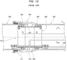
watertightness testing device 201 as shown inFIG. 16 . Specifically, thewatertightness testing device 201 includes atesting device body 205 which performs a watertightness test of a joinedsection 204 ofpipes pipes moving operation rod 206 for moving thetesting device body 205 inside thepipes - The
testing device body 205 includes a cylindrical member 207 and a pair of annularwater stop bags 208 which are provided in the cylindrical member 207 and of which a diameter-expanding operation can be performed. An annular sealedspace 209 enclosed by bothwater stop bags 208 of which a diameter-expanding operation has been performed to a water-stopping state, an outer circumferential surface of the cylindrical member 207, and inner circumferential surfaces of thepipes section 204. - The
testing device body 205 inspects water leakage from anelastic seal 211 of the joinedsection 204 by supplyingwater 210 for a water pressure test to inside of the sealedspace 209 and applying water pressure. - The moving
operation rod 206 is attached to the cylindrical member 207 of thetesting device body 205 and extends along the pipe axial direction B. - Accordingly, after joining a
second pipe 203 to afirst pipe 202, the movingoperation rod 206 is operated to move thetesting device body 205 to the joinedsection 204. Subsequently, diameters of bothwater stop bags 208 are expanded, thewater 210 for a water pressure test is supplied to the inside of the sealedspace 209, and water pressure is applied in order to inspect water leakage from theelastic seal 211 of the joinedsection 204. - Refer to
Japanese Patent Laid-Open No. 2013-40866 watertightness testing device 201 described above. - However, in the conventional form described above, when performing a watertightness test, there is a risk that the
second pipe 203 may become pressed in a separating direction H by water pressure acting inside the annular sealedspace 209 and that thesecond pipe 203 may become detached from thefirst pipe 202. - An object of the present invention is to provide a watertightness testing method and an assembling device capable of preventing a second pipe from becoming detached from a first pipe during a watertightness test.
- A watertightness testing method according to the present invention for testing watertightness of a joined section where one end section of a second pipe is joined to a first pipe includes:
- inserting, into the first pipe, a testing device body of a watertightness testing device for performing a watertightness test inside a pipe;
- attaching an assembling device to another end section of the second pipe;
- attaching a pulling device to the assembling device and connecting the pulling device to a strap-shaped member having been wound in advance around an outer circumference of the first pipe;
- operating the pulling device and pulling the strap-shaped member in a separating direction of the second pipe to have a reaction force generated in the second pipe cause the second pipe to be pulled in a joining direction, the one end section of the second pipe to be inserted into an end section of the first pipe, and the one end section of the second pipe to be joined to the first pipe; and
- operating a moving operation rod provided in the testing device body from outside of the other end section of the second pipe in a state where the second pipe is being pulled in the joining direction to move the testing device body to the joined section inside the pipe and performing a watertightness test of the joined section.
- Accordingly, since a watertightness test of a joined section is performed using the testing device body in a state where, after the second pipe is joined to the first pipe, the second pipe is being pulled in a joining direction, the second pipe is restrained by the first pipe via the assembling device, the pulling device, and the strap-shaped member in the pipe axial direction while the watertightness test is in progress. As a result, the second pipe can be prevented from becoming detached from the first pipe.
- With the watertightness testing method according to the present invention, preferably, when operating the moving operation rod from outside of the other end section of the second pipe to move the testing device body to the joined section inside the pipe, the moving operation rod is passed through a passage space secured in a central part of the other end section of the second pipe and pulled outside from the other end section of the second pipe without interfering with the assembling device.
- Accordingly, since the moving operation rod does not interfere with the assembling device when the moving operation rod is operated from outside of the other end section of the second pipe, the moving operation rod can be readily pulled outside from the other end section of the second pipe.
- An assembling device used in the watertightness testing method according to the present invention includes:
- a frame body attachable to and detachable from the other end section of the second pipe and an attaching section for attaching the pulling device to the frame body, wherein
- the attaching section is provided on the frame body, and
- the frame body can be attached to the other end section of the second pipe to be arranged in a periphery of the passage space for pulling out the moving operation rod.
- Accordingly, the passage space is secured in the other end section of the second pipe in a state where the frame body is attached to the other end section of the second pipe. As a result, the moving operation rod is passed through the passage space and pulled outside from the other end section of the second pipe without interfering with the assembling device.
- With the assembling device according to the present invention, preferably, the attaching section is provided outside in a pipe diameter direction of the frame body,
- a fall prevention device for preventing the frame body attached to the other end section of the second pipe from falling outward in the pipe diameter direction is provided on the frame body, and
- the fall prevention device has a rolling element that can be brought into contact with a wall surface surrounding the pipe.
- Accordingly, by attaching the frame body of the assembling device to the other end section of the second pipe and attaching the pulling device to the attaching section of the frame body, the pulling device is arranged outside in the pipe diameter direction of the frame body.
- When the strap-shaped member is pulled in the separating direction of the second pipe by operating the pulling device in this state, an outward external force in the pipe diameter direction acts on the frame body. However, due to the rolling element of the fall prevention device coming into contact with the wall surface against the external force, the frame body is supported on a side of the wall surface by the fall prevention device. Accordingly, the frame body can be prevented from falling outward in the pipe diameter direction.
- In addition, when joining the second pipe to the first pipe, since the rolling element of the fall prevention device rolls in the joining direction while maintaining contact with the wall surface as the second pipe moves in the joining direction, the assembling device smoothly moves together with the second pipe in the joining direction.
- With the assembling device according to the present invention, preferably, the fall prevention device has a position adjuster that moves a position of the rolling element in the pipe diameter direction.
- Accordingly, by moving the position of the rolling element in the pipe diameter direction in accordance with a position of the wall surface, the rolling element can be reliably brought into contact with the wall surface.
- As described above, according to the present invention, a watertightness test of a joined section is performed using the testing device body in a state where, after joining the second pipe to the first pipe, the second pipe is being pulled in a joining direction. Therefore, while the watertightness test is in progress, the second pipe is restrained by the first pipe via the assembling device, the pulling device, and the strap-shaped member in the pipe axial direction. Accordingly, the second pipe can be prevented from becoming detached from the first pipe.
-
- [
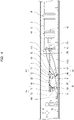
FIG. 1] FIG. 1 is a sectional view of a testing device body of a watertightness testing device used in a watertightness testing method according to a first embodiment of the present invention showing a state where indentation of first and second sealing members has been released. - [
FIG. 2] FIG. 2 is a sectional view of the testing device body of the watertightness testing device according to the first embodiment of the present invention showing a state where the first and second sealing members have been indented. - [
FIG. 3] FIG. 3 is an arrow view taken along X-X inFIG. 1 . - [
FIG. 4] FIG. 4 is a side view showing a procedure of the watertightness testing method using the watertightness testing device according to the first embodiment of the present invention. - [
FIG. 5] FIG. 5 is a side view showing a procedure of the watertightness testing method using the watertightness testing device according to the first embodiment of the present invention. - [
FIG. 6] FIG. 6 is a side view showing a procedure of the watertightness testing method using the watertightness testing device according to the first embodiment of the present invention. - [
FIG. 7] FIG. 7 is a side view showing a procedure of the watertightness testing method using the watertightness testing device according to the first embodiment of the present invention. - [
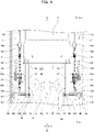
FIG. 8] FIG. 8 is an arrow view taken along X-X inFIG. 6 . - [
FIG. 9] FIG. 9 is an arrow view taken along X-X inFIG. 8 . - [
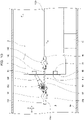
FIG. 10] FIG. 10 is an arrow view taken along X-X inFIG. 9 . - [
FIG. 11] FIG. 11 is a front view of one of two frame bodies of an assembling device used in the watertightness testing method according to the first embodiment of the present invention. - [
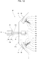
FIG. 12] FIG. 12 is a rear view of one of the frame bodies of the assembling device according to the first embodiment of the present invention. - [
FIG. 13] FIG. 13 is a plan view of one of the frame bodies of the assembling device according to the first embodiment of the present invention. - [
FIG. 14] FIG. 14 is a side view of one of the frame bodies of the assembling device according to the first embodiment of the present invention. - [
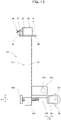
FIG. 15] FIG. 15 is a front view of an assembling device according to a second embodiment. - [
FIG. 16] FIG. 16 is a sectional view for describing a watertightness testing method using a conventional watertightness testing device. - Hereinafter, embodiments of the present invention will be described with reference to the drawings.
- In the first embodiment, as shown in
FIGS. 1 to 3 ,reference numeral 1 denotes a watertightness testing device for performing a watertightness test of a joinedsection 4 between joinedpipes pipes spigot 6 at one end section and asocket 7 at another end section. Thepipes FIG. 4 ) formed underground and constitute a conduit 10 (refer toFIG. 4 ). Thepipes inner wall surface 9a of theconduit installation tunnel 9. - In the joined
section 4, joining is achieved by inserting thespigot 6 of asecond pipe 3 into thesocket 7 of afirst pipe 2. A locking-ring housing groove 12 and a sealingbody mounting depression 13 are formed on an inner circumferential surface of thesocket 7. - A locking-
ring 15 for preventing separation is housed in the locking-ring housing groove 12. In addition, anannular sealing body 16 made of an elastic material such as rubber is mounted to the sealingbody mounting depression 13. The sealingbody 16 is sandwiched between an outer circumferential surface of thespigot 6 and the inner circumferential surface of thesocket 7 and compressed in a pipe diameter direction A. Accordingly, sealing is achieved between thespigot 6 and thesocket 7. - As shown in
FIG. 4 , thewatertightness testing device 1 includes atesting device body 21 which performs a watertightness test of the joinedsection 4 inside thepipes operation rod 22 for moving thetesting device body 21 inside thepipes - The
testing device body 21 will be described below. - As shown in
FIGS. 1 to 3 , thetesting device body 21 has acylindrical core 25, first andsecond sealing members members device 32, a testingfluid supplying device 33, and a supportingdevice 34. - The
first sealing member 26 is an annular member made of an elastic material such as rubber and provides a seal between an outer circumferential surface of thecore 25 and an inner circumferential surface of thesecond pipe 3. In addition, the second sealingmember 27 is an annular member made of an elastic material such as rubber and provides a seal between the outer circumferential surface of thecore 25 and an inner circumferential surface of thefirst pipe 2. - An engaging depression 36 is respectively formed around a whole circumference on an outer circumferential surface of a proximal end section of the first and
second sealing members - A first sealing
member insertion space 37 is formed around a whole circumference between the outer circumferential surface of thecore 25 and the inner circumferential surface of thesecond pipe 3. In addition, a second sealingmember insertion space 38 is formed around a whole circumference between the outer circumferential surface of thecore 25 and the inner circumferential surface of thefirst pipe 2. - The first indenting
member 29 indents and compresses the first sealingmember 26 into the first sealingmember insertion space 37 and has an engaging protrusion 40 formed around a whole circumference. - In addition, the second indenting
member 30 indents and compresses the second sealingmember 27 into the second sealingmember insertion space 38 and has the engaging protrusion 40 in a similar manner to the first indentingmember 29. - The engaging protrusion 40 of the first indenting
member 29 is fitted into the engaging depression 36 of the first sealingmember 26. Accordingly, the first sealingmember 26 and the first indentingmember 29 engage each other in the pipe axial direction B. In addition, the engaging protrusion 40 of the second indentingmember 30 is fitted into the engaging depression 36 of the second sealingmember 27. Accordingly, the second sealingmember 27 and the second indentingmember 30 engage each other in the pipe axial direction B. - The moving
device 32 is a device that moves the first indentingmember 29 and the second indentingmember 30 in an indenting direction C (refer toFIG. 2 ) in which both indentingmembers FIG. 1 ) in which both indentingmembers - Specifically, the moving
device 32 has a pipe-likemobile rod 42 which is attached to the second indentingmember 30 and which is movable in the pipe axial direction B, a receivingmember 43 provided in a tip section of themobile rod 42, and a plurality of double-actingjacks 44 that are extensible and retractable in the pipe axial direction B. The double-actingjacks 44 are attached between the first indentingmember 29 and the receivingmember 43. As shown inFIG. 7 , ahydraulic oil pump 59 is connected to the double-actingjacks 44 viahydraulic oil piping 58. By activating thehydraulic oil pump 59, aplunger 45 of the double-actingjacks 44 is extended and retracted. - As shown in
FIGS. 1 to 3 , the supportingdevice 34 is a device that supports the core 25, the first and second indentingmembers device 32 and has ashaft 46 inserted into themobile rod 42, a plurality of leg frames 47 provided in both end sections of theshaft 46, and a movingwheel 48 rotatably provided in a lower end section of the leg frames 47. The movingwheels 48 are distributed in a pipe circumferential direction E and are capable of rolling on the innercircumferential surfaces pipes - As shown in
FIG. 2 , when the first and second indentingmembers second sealing members member insertion spaces - In addition, as shown in
FIG. 1 , when the first and second indentingmembers second sealing members - As shown in
FIGS. 1 and2 , when thetesting device body 21 is set to the joinedsection 4 in thepipes test space 50 is formed around a whole circumference between the outer circumferential surface of thecore 25 and the innercircumferential surfaces pipes member 26 and the second sealingmember 27 in the pipe axial direction B. Thetest space 50 is communicated with the sealingbody mounting depression 13 via agap 51 between a deep end of thesocket 7 and a tip of thespigot 6. - The testing
fluid supplying device 33 is a device that supplies thetest space 50 with water 53 (an example of a testing fluid) from inside thecore 25 and has awater supply hose 54 connected to a lower part of an inner circumference of thecore 25 and a hydraulic pump 55 (refer toFIG. 7 ) provided at a tip of thewater supply hose 54. - In addition, an
air vent hose 57 for deaerating an inside of thetest space 50 is connected to an upper part of the inner circumference of thecore 25. Thewater supply hose 54 and theair vent hose 57 penetrate the first indentingmember 29. - As shown in
FIG. 4 , the movingoperation rod 22 has an elongated operation rodmain body 60 which is attachably and detachably coupled to a tip section of theshaft 46 of thetesting device body 21 and which extends in the pipe axial direction B, first and second main supportingmembers main body 60 on aninner wall surface 9a of theconduit installation tunnel 9 outside of thepipes auxiliary supporting members main body 60 on the innercircumferential surface 3a inside thesecond pipe 3. Thewater supply hose 54, theair vent hose 57, and the hydraulic oil piping 58 are arranged along the movingoperation rod 22 from thetesting device body 21. - Each of the first and second main supporting
members leg frame 67 suspended downward from the operation rodmain body 60 and a pair ofmain wheels 68 provided in a lower end section of theleg frame 67. The pair ofmain wheels 68 are distributed in the pipe circumferential direction E. - In addition, the
leg frame 67 can be switched between a supporting posture K (refer toFIG. 4 ) in which theleg frame 67 extends in the pipe diameter direction A and a folded posture L (refer toFIG. 5 ) in which theleg frame 67 is folded inside thepipe 3. Theleg frame 67 is urged from the folded posture L to the supporting posture K by aspring cylinder 69. - Each of the first and second
auxiliary supporting members frame 71 attached to a lower side of the operation rodmain body 60 and a pair ofauxiliary wheels 72 provided in a lower end section of the attachedframe 71. As shown inFIG. 8 , the pair ofauxiliary wheels 72 are distributed in the pipe circumferential direction E. - In addition, when a watertightness test of the joined
section 4 of thepipes device 80 such as that shown inFIGS. 8 to 14 is used. - As shown in
FIGS. 6 to 10 , the assemblingdevice 80 has a pair offrame bodies socket 7 of thesecond pipe 3 and which are divided left and right and attachingplates frame bodies - Each of the lever hoists 82a and 82b has an
anchor hook 141 provided on a main body side and a connectinghook 143 provided on a tip of achain 142. - As shown in
FIGS. 11 and12 , oneframe body 81a has a mountingplate 86 which is attachable to and detachable from the opening end surface of thesocket 7, astrut 87 which is provided on a front surface of the mountingplate 86 and which extends in the pipe axial direction B, two sets of clampingmechanisms 88 which sandwich the opening end section of thesocket 7 in the pipe diameter direction A, and afall prevention device 89 for preventing the frame bodies 81 attached to the opening end section of thesocket 7 of thesecond pipe 3 from falling toward outside 90 in the pipe diameter direction A. - Each of the two clamping
mechanisms 88 has a pair of a fixedplate 91 and amobile plate 92 which oppose each other in the pipe diameter direction A and a movingmember 93 which moves themobile plate 92 relative to the fixedplate 91 in the pipe diameter direction A. The fixedplate 91 is fixed to a rear surface of the mountingplate 86. - The moving
member 93 has abolt body 94 having a male screw on an outer circumference thereof, an engagingpiece 95 provided on a tip of thebolt body 94, an engagingmember 96 provided on themobile plate 92, and a supportingplate 97 which supports thebolt body 94. - The supporting
plate 97 is provided on the rear surface of the mountingplate 86 and ascrew hole 98 having a female screw is formed on the supportingplate 97. Thebolt body 94 is rotatably inserted through thescrew hole 98 in a state where the male screw and the female screw are screwed and thebolt body 94 is supported by the supportingplate 97. A diameter of the engagingpiece 95 is larger than that of thebolt body 94 and the engagingpiece 95 and the engagingmember 96 engage each other in an axial center direction of thebolt body 94. - As shown in
FIG. 13 , one of the attachingplates 83a has an attachinghole 100 and is provided on an outside surface of thestrut 87 of one of theframe bodies 81a in the pipe diameter direction A. - As shown in
FIGS. 8 to 10 and13 , thefall prevention device 89 has a roller 101 (an example of a rolling element) which can come into contact with theinner wall surface 9a of theconduit installation tunnel 9 and aposition adjuster 102 which moves a position of theroller 101 in the pipe diameter direction A. - The
position adjuster 102 has ascrew shaft 103 which penetrates thestrut 87 of the frame bodies 81 in the pipe diameter direction A, abracket 104 provided on a tip of thescrew shaft 103, and anoperating handle 106 for rotationally operating thescrew shaft 103. Theroller 101 is rotatably provided on thebracket 104. - In addition, the
screw shaft 103 has a male screw on an outer circumference thereof and screws with a female screw of anut body 105 provided on thestrut 87. Thescrew shaft 103 and thebracket 104 are relatively rotatably coupled to each other around an axial center of thescrew shaft 103. - While the one
frame body 81a is configured as described above, theother frame body 81b is also configured in a same manner as the oneframe body 81a. - According to the assembling
device 80 described above, as indicated by an imaginary line inFIG. 12 , the opening end section of thesocket 7 is inserted between the fixedplate 91 and themobile plate 92 of theclamping mechanism 88 of the oneframe body 81a and thebolt body 94 is rotated in one direction to bring themobile plate 92 close to the fixedplate 91. Accordingly, a distance between the fixedplate 91 and themobile plate 92 in the pipe diameter direction A is reduced, the opening end section of thesocket 7 is sandwiched between the fixedplate 91 and themobile plate 92, and the oneframe body 81a is attached to the opening end section of thesocket 7 as shown inFIGS. 8 to 10 . - In addition, in a similar manner to attaching the one
frame body 81a, theother frame body 81b can be attached to the opening end section of thesocket 7. - A watertightness testing method of testing watertightness of the joined
section 4 of thepipes watertightness testing device 1 described above will be described below. - As shown in
FIG. 4 , thefirst pipe 2 is a pipe at a tail end of theconduit 10 which has already been joined inside theconduit installation tunnel 9 and is supported by a support table 111 made of crossties or the like. In this state, first, thetesting device body 21 of thewatertightness testing device 1 is inserted into thefirst pipe 2. - At this point, the operation rod
main body 60 of the movingoperation rod 22 protrudes outside of an end section of thefirst pipe 2 from thesocket 7 of thefirst pipe 2 and is supported on theinner wall surface 9a of theconduit installation tunnel 9 by the first and second main supportingmembers - The locking-
ring 15 has been housed in advance in the locking-ring housing groove 12 and the sealingbody 16 has been mounted in advance to the sealingbody mounting depression 13 inside thesocket 7 of thefirst pipe 2. - In addition, the
plunger 45 of the double-actingjack 44 of thetesting device body 21 is shortened and the first and second indentingmembers FIG. 1 ). - Furthermore, as shown in
FIG. 4 , twosling belts socket 7 of thefirst pipe 2 in advance in a state of being distributed left and right (refer toFIG. 9 ). At the same time, arecovery rope 113 for recovering bothsling belts sling belts sling belts eye sections - Next, as shown in
FIG. 5 , thesecond pipe 3 is loaded on atransfer carriage 115 and thetransfer carriage 115 is caused to travel in a joining direction G to transfer thesecond pipe 3 up to a front side of thefirst pipe 2. - In doing so, due to an opening end section of the
spigot 6 of thesecond pipe 3 coming into contact with the first and second main supportingmembers operation rod 22 of thewatertightness testing device 1, the leg frames 67 of the first and second main supportingmembers operation rod 22 is inserted into thesecond pipe 3. At this point, the operation rodmain body 60 is supported on the innercircumferential surface 3a of thesecond pipe 3 by the first and secondauxiliary supporting members - Subsequently, the assembling
device 80 is attached to the opening end section of thesocket 7 of thesecond pipe 3. Specifically, as indicated by an imaginary line inFIG. 12 , by inserting the opening end section of thesocket 7 of thesecond pipe 3 between the fixedplate 91 and themobile plate 92 of the oneframe body 81a and rotating thebolt body 94 in one direction to bring themobile plate 92 close to the fixedplate 91, the opening end section of thesocket 7 of thesecond pipe 3 is sandwiched between themobile plate 92 and the fixedplate 91 in the pipe diameter direction A. Accordingly, as shown inFIGS. 6 and8 to 10, the oneframe body 81a is attached to the opening end section of thesocket 7 of thesecond pipe 3. - By attaching the
other frame body 81b to the opening end section of thesocket 7 of thesecond pipe 3 in a similar manner, the assemblingdevice 80 is attached to the opening end section of thesocket 7 of thesecond pipe 3. - In doing so, as shown in
FIGS. 8 and9 , apassage space 117 for pulling out the movingoperation rod 22 is secured between the oneframe body 81a and theother frame body 81b in a central part of the socket 7 (the other end section) of thesecond pipe 3 and in the pipe diameter direction A. The one and theother frame bodies passage space 117. - In addition, as shown in
FIGS. 9 and10 , theanchor hook 141 of one lever hoist 82a is hooked to the attachinghole 100 of one attachingplate 83a and the connectinghook 143 is hooked to theeye section 146 of onesling belt 112a. Furthermore, theanchor hook 141 of the other lever hoist 82b is hooked to the attachinghole 100 of the other attachingplate 83b and the connectinghook 143 is hooked to theeye section 146 of theother sling belt 112b. - Accordingly, both left and right lever hoists 82a and 82b are attached to the assembling
device 80 and connected to both left andright sling belts FIG. 9 , the one lever hoist 82a is positioned toward outside in the pipe diameter direction A of the oneframe body 81a and the other lever hoist 82b is positioned toward outside in the pipe diameter direction A of theother frame body 81b. - Subsequently, as shown in
FIGS. 6 ,9 , and10 , due to aworker 118 operating alever 144 of both lever hoists 82a and 82b, bothsling belts second pipe 3 and a reaction force F is generated in thesecond pipe 3 in reaction thereto. Thesecond pipe 3 is pulled in the joining direction G by the reaction force F and the spigot 6 (the one end section) of thesecond pipe 3 is inserted into thesocket 7 of thefirst pipe 2. Accordingly, thesecond pipe 3 is joined to thefirst pipe 2. - In doing so, as shown in
FIGS. 6 ,8 , and9 , a tip section of the movingoperation rod 22 of thewatertightness testing device 1 passes through thepassage space 117 and protrudes outside of an end section from thesocket 7 of thesecond pipe 3 without interfering with the assemblingdevice 80. In addition, thesecond pipe 3 is supported by the support table 111. - As described above, in a state where the
second pipe 3 is being pulled in the joining direction G using the lever hoists 82a and 82b, as shown inFIG. 7 , theworker 118 operates the tip section of the movingoperation rod 22 of thewatertightness testing device 1 from outside of an end section of thesocket 7 of thesecond pipe 3 and moves thetesting device body 21 to the joinedsection 4 of thepipes - In doing so, as shown in
FIGS. 8 and9 , the movingoperation rod 22 passes through thepassage space 117 and protrudes outside of the end section from thesocket 7 of thesecond pipe 3 without interfering with the assemblingdevice 80. Therefore, the movingoperation rod 22 can be readily pulled outside from thesocket 7 of thesecond pipe 3. At this point, as shown inFIG. 7 , since the first main supportingmember 61 is pulled outside of thesecond pipe 3 and switched from the folded posture L to the supporting posture K, the operation rodmain body 60 is supported on theinner wall surface 9a of theconduit installation tunnel 9 by the first main supportingmember 61. - In addition, as shown in
FIG. 1 , since the first and second indentingmembers second sealing members testing device body 21 can be readily moved in the pipe axial direction B. - Subsequently, a watertightness test of the joined
section 4 is performed using thetesting device body 21. In doing so, as shown inFIG. 2 , by activating the hydraulic oil pump 59 (refer toFIG. 7 ) and extending theplunger 45 of the double-actingjack 44, the first indentingmember 29 moves in the indenting direction C and reaches the indenting position P1. At the same time, themobile rod 42 of the movingdevice 32 moves in an opposite direction J to the first indentingmember 29 and the second indentingmember 30 moves in the indenting direction C and reaches the indenting position P1. - Accordingly, the first indenting
member 29 indents the first sealingmember 26 into the first sealingmember insertion space 37 and compresses the first sealingmember 26 and the second indentingmember 30 indents the second sealingmember 27 into the second sealingmember insertion space 38 and compresses the second sealingmember 27. As a result, a space between the outer circumferential surface of thecore 25 and the inner circumferential surface of thesecond pipe 3 is sufficiently sealed by the compressed first sealingmember 26 and a space between the outer circumferential surface of thecore 25 and the inner circumferential surface of thefirst pipe 2 is sufficiently sealed by the compressed second sealingmember 27. - Subsequently, the hydraulic pump 55 (refer to
FIG. 7 ) is activated to supplywater 53 to thetest space 50 from thewater supply hose 54. Accordingly, while air inside thetest space 50 and inside the sealingbody mounting depression 13 is discharged through theair vent hose 57, thewater 53 supplied to thetest space 50 passes through thegap 51 and fills the sealingbody mounting depression 13. In a state where thetest space 50 and the sealingbody mounting depression 13 are filled with thewater 53 with predetermined pressure in this manner, a watertightness test of the joinedsection 4 of thepipes water 53 from the sealingbody 16. - According to the watertightness testing method described above, as shown in
FIG. 7 , since a watertightness test of the joinedsection 4 of thepipes testing device body 21 in a state where thesecond pipe 3 is being pulled in the joining direction G after joining thesecond pipe 3 to thefirst pipe 2 using the lever hoists 82a and 82b, thesecond pipe 3 is restrained by thefirst pipe 2 via the assemblingdevice 80, the lever hoists 82a and 82b, and thesling belts FIG. 2 , thesecond pipe 3 can be prevented from becoming detached from thefirst pipe 2 by pressure of thewater 53 that fills thetest space 50 and the sealingbody mounting depression 13 during the watertightness test. - In addition, as shown in
FIG. 6 , when theworker 118 operates thelever 144 of the one lever hoist 82a and pulls the onesling belt 112a in the separating direction H of thesecond pipe 3, as shown inFIG. 9 , an outward external force f in the pipe diameter direction A acts on the oneframe body 81a. As theroller 101 of thefall prevention device 89 comes into contact with theinner wall surface 9a of theconduit installation tunnel 9 against the external force f, the oneframe body 81a is supported on a side of theinner wall surface 9a by thefall prevention device 89. Accordingly, the oneframe body 81a can be prevented from falling toward outside 90 in the pipe diameter direction A. - In a similar manner, since the
other frame body 81b is also supported on the side of theinner wall surface 9a of theconduit installation tunnel 9 by thefall prevention device 89, theother frame body 81b can be prevented from falling toward outside 90 in the pipe diameter direction A. - In addition, when joining the
second pipe 3 to thefirst pipe 2, since theroller 101 of thefall prevention device 89 rolls in the joining direction G while maintaining contact with theinner wall surface 9a of theconduit installation tunnel 9 as thesecond pipe 3 moves in the joining direction G, the assemblingdevice 80 smoothly moves together with thesecond pipe 3 in the joining direction G. - Furthermore, by operating the operating handle 106 of the
position adjuster 102 and rotating thescrew shaft 103, the position of theroller 101 moves in the pipe diameter direction A. Accordingly, by moving the position of theroller 101 in the pipe diameter direction A in accordance with a position of theinner wall surface 9a of theconduit installation tunnel 9, theroller 101 can be reliably brought into contact with theinner wall surface 9a of theconduit installation tunnel 9. - In addition, after performing a watertightness test of the joined
section 4 as described above, by repetitively performing a procedure including temporarily detaching the assemblingdevice 80, the lever hoists 82a and 82b, and thesling belts second pipe 3, and performing a watertightness test of the joined section, a watertightness test of a joined section can be performed while joining pipes to each other. - As shown in
FIG. 12 , by rotating thebolt body 94 of the assemblingdevice 80 in the other direction to separate themobile plate 92 from the fixedplate 91 and detaching bothframe bodies socket 7 of thesecond pipe 3, thetesting device body 21 can be taken outside from the opening end section of thesocket 7 of thesecond pipe 3. - Furthermore, by operating the
recovery rope 113 after detaching theframe bodies device 80, thesling belts socket 7 of thefirst pipe 2 and can be recovered. - While an assembling
device 80 has a pair offrame bodies FIG. 8 in the first embodiment described above, as a second embodiment, a mountingplate 86 of oneframe body 81a and a mountingplate 86 of anotherframe body 81b may be coupled to each other by a pair of upper and lower coupling frames 125 and 126. In this case, apassage space 117 is secured between the left andright backing plates 86 of theframe bodies - In addition, in the respective embodiments described above, while the two
frame bodies socket 7 of thesecond pipe 3 by being distributed at angles that differ by 180 degrees as shown inFIG. 8 , the number of frame bodies is not limited to two. For example, three frame bodies may be attached to thesocket 7 of thesecond pipe 3 by being distributed at angles that differ by 120 degrees. - Furthermore, in the respective embodiments described above, while a moving
operation rod 22 has an operation rodmain body 60, main supportingmembers members FIG. 4 , the movingoperation rod 22 may not include at least one of the main supportingmembers members - Moreover, while a case where pipes are laid in a
conduit installation tunnel 9 that is an existing pipeline, a tunnel, a shield, or the like has been described in the embodiments presented above, the present invention is not limited to cases inside theconduit installation tunnel 9 and can also be applied to a case (an open-cut method) in which pipes are laid inside a groove cut out from ground.
Claims (5)
- A watertightness testing method for testing watertightness of a joined section where one end section of a second pipe is joined to a first pipe, the watertightness testing method comprising:inserting, into the first pipe, a testing device body of a watertightness testing device for performing a watertightness test inside a pipe;attaching an assembling device to another end section of the second pipe;attaching a pulling device to the assembling device and connecting the pulling device to a strap-shaped member having been wound in advance around an outer circumference of the first pipe;operating the pulling device and pulling the strap-shaped member in a separating direction of the second pipe to have a reaction force generated in the second pipe cause the second pipe to be pulled in a joining direction, the one end section of the second pipe to be inserted into an end section of the first pipe, and the one end section of the second pipe to be joined to the first pipe; andoperating a moving operation rod provided in the testing device body from outside of the other end section of the second pipe in a state where the second pipe is being pulled in the joining direction to move the testing device body to the joined section inside the pipe and performing a watertightness test of the joined section.
- The watertightness testing method according to claim 1, wherein when operating the moving operation rod from outside of the other end section of the second pipe to move the testing device body to the joined section inside the pipe, the moving operation rod is passed through a passage space secured in a central part of the other end section of the second pipe and pulled outside from the other end section of the second pipe without interfering with the assembling device.
- An assembling device used in the watertightness testing method according to claim 1 or 2, the assembling device comprising:a frame body attachable to and detachable from the other end section of the second pipe and an attaching section for attaching the pulling device to the frame body, whereinthe attaching section is provided on the frame body, and the frame body can be attached to the other end section of the second pipe to be arranged in a periphery of the passage space for pulling out the moving operation rod.
- The assembling device according to claim 3, whereinthe attaching section is provided outside in a pipe diameter direction of the frame body,a fall prevention device for preventing the frame body attached to the other end section of the second pipe from falling outward in the pipe diameter direction is provided on the frame body, andthe fall prevention device has a rolling element that can be brought into contact with a wall surface surrounding the pipe.
- The assembling device according to claim 4, wherein the fall prevention device has a position adjuster that moves a position of the rolling element in the pipe diameter direction.
Applications Claiming Priority (2)
| Application Number | Priority Date | Filing Date | Title |
|---|---|---|---|
| JP2020044864A JP7344819B2 (en) | 2020-03-16 | 2020-03-16 | Watertightness test method and bonding jig |
| PCT/JP2021/010302 WO2021187404A1 (en) | 2020-03-16 | 2021-03-15 | Watertightness testing method and joining jig |
Publications (2)
| Publication Number | Publication Date |
|---|---|
| EP4119917A1 true EP4119917A1 (en) | 2023-01-18 |
| EP4119917A4 EP4119917A4 (en) | 2023-08-23 |
Family
ID=77770937
Family Applications (1)
| Application Number | Title | Priority Date | Filing Date |
|---|---|---|---|
| EP21771069.8A Pending EP4119917A4 (en) | 2020-03-16 | 2021-03-15 | WATER LEAK TEST PROCEDURE AND ASSEMBLY JIG |
Country Status (6)
| Country | Link |
|---|---|
| US (1) | US12196644B2 (en) |
| EP (1) | EP4119917A4 (en) |
| JP (1) | JP7344819B2 (en) |
| CN (1) | CN115210550B (en) |
| CA (1) | CA3169713A1 (en) |
| WO (1) | WO2021187404A1 (en) |
Families Citing this family (3)
| Publication number | Priority date | Publication date | Assignee | Title |
|---|---|---|---|---|
| JP7344818B2 (en) * | 2020-03-16 | 2023-09-14 | 株式会社クボタ | Watertightness test equipment and watertightness test method |
| JP7844380B2 (en) * | 2023-03-22 | 2026-04-13 | 株式会社栗本鐵工所 | Lubrication device and pipe connection method |
| CN120102025B (en) * | 2025-05-07 | 2025-07-08 | 卡耐夫集团(山西)管道系统有限公司 | Air tightness test pressing machine for groove elbow pipe fitting |
Family Cites Families (15)
| Publication number | Priority date | Publication date | Assignee | Title |
|---|---|---|---|---|
| GB1306623A (en) * | 1971-05-11 | 1973-02-14 | Flexadux Plastics Ltd | Flexible ducting |
| JP2682766B2 (en) * | 1991-12-20 | 1997-11-26 | 株式会社クボタ | Pipe joining equipment |
| US5323641A (en) * | 1992-05-29 | 1994-06-28 | Tolliver Wilbur E | Pipe joint seal tester |
| JP3570907B2 (en) * | 1998-11-09 | 2004-09-29 | 株式会社クボタ | Jig for pipe joining |
| JP2006084474A (en) * | 2005-09-26 | 2006-03-30 | Kurimoto Ltd | Hydraulic pressure tester |
| JP5722729B2 (en) | 2011-08-17 | 2015-05-27 | さいたま市 | Water pressure testing machine |
| JP5725558B2 (en) | 2011-12-07 | 2015-05-27 | さいたま市 | In-pipe carry-in guide device for water pressure tester |
| JP6142428B2 (en) * | 2013-02-15 | 2017-06-07 | さいたま市 | Water pressure testing machine |
| JP6294627B2 (en) * | 2013-10-09 | 2018-03-14 | 株式会社クボタ | Pipe joint structure, seal member, joint state management method for pipe joint, and joint state management apparatus for pipe joint |
| JP2015099056A (en) * | 2013-11-18 | 2015-05-28 | 早川ゴム株式会社 | Watertight testing device of water-stop joint provided at pipeline connection |
| JP6845412B2 (en) | 2015-08-31 | 2021-03-17 | 横浜市 | Water pressure test equipment |
| US11384875B2 (en) * | 2016-03-28 | 2022-07-12 | Kubota Corporation | Pipe joint, separation prevention member, and method of connecting pipes |
| CN107035918A (en) * | 2017-06-07 | 2017-08-11 | 天津市源泉市政工程有限公司 | One kind feedwater pipe fitting engineering construction method |
| JP6932062B2 (en) * | 2017-10-23 | 2021-09-08 | 株式会社クボタ | Piping completion drawing creation system and piping construction drawing creation method, as well as flying objects and pipe joint position calculation devices used in the piping completion drawing creation system |
| CN207921543U (en) * | 2018-03-19 | 2018-09-28 | 陈伟 | A kind of water supply and drainage pipe reducing connection structure |
-
2020
- 2020-03-16 JP JP2020044864A patent/JP7344819B2/en active Active
-
2021
- 2021-03-15 CA CA3169713A patent/CA3169713A1/en active Pending
- 2021-03-15 CN CN202180018172.XA patent/CN115210550B/en active Active
- 2021-03-15 EP EP21771069.8A patent/EP4119917A4/en active Pending
- 2021-03-15 WO PCT/JP2021/010302 patent/WO2021187404A1/en not_active Ceased
- 2021-03-15 US US17/911,865 patent/US12196644B2/en active Active
Also Published As
| Publication number | Publication date |
|---|---|
| CN115210550B (en) | 2025-03-07 |
| JP7344819B2 (en) | 2023-09-14 |
| JP2021148428A (en) | 2021-09-27 |
| CN115210550A (en) | 2022-10-18 |
| WO2021187404A1 (en) | 2021-09-23 |
| EP4119917A4 (en) | 2023-08-23 |
| US20230139386A1 (en) | 2023-05-04 |
| US12196644B2 (en) | 2025-01-14 |
| CA3169713A1 (en) | 2021-09-23 |
Similar Documents
| Publication | Publication Date | Title |
|---|---|---|
| US12196644B2 (en) | Watertightness testing method and assembling device | |
| JP6336567B2 (en) | Apparatus and method for separating part of riser pipe lumen during riser refurbishment process | |
| AU2013200494B2 (en) | Low Pressure Hot Tap Pipeline Isolation | |
| US4858464A (en) | Portable pipe testing apparatus | |
| US4470946A (en) | Removable pipeline plug | |
| CA2656942A1 (en) | Test tool & method for testing a tubular component | |
| GB2456229A (en) | Tool for isolating a pipeline portion | |
| CN115717966A (en) | Air tightness detection device and method for corrugated pipe | |
| US20110188943A1 (en) | Rod Pulling And Pushing Machine For Pipe Bursting | |
| US12209698B2 (en) | Pipeline isolation tool, assembly and method | |
| EP4119918B1 (en) | Watertightness testing device and watertightness testing method | |
| US7628056B2 (en) | Internal pressure testing apparatus and method for pipe | |
| NO177683B (en) | Method and apparatus for repairing an underwater pipeline | |
| JP4294458B2 (en) | Segment ring shape retention method | |
| JP2009270969A (en) | Tool for leak test |
Legal Events
| Date | Code | Title | Description |
|---|---|---|---|
| STAA | Information on the status of an ep patent application or granted ep patent |
Free format text: STATUS: THE INTERNATIONAL PUBLICATION HAS BEEN MADE |
|
| PUAI | Public reference made under article 153(3) epc to a published international application that has entered the european phase |
Free format text: ORIGINAL CODE: 0009012 |
|
| STAA | Information on the status of an ep patent application or granted ep patent |
Free format text: STATUS: REQUEST FOR EXAMINATION WAS MADE |
|
| 17P | Request for examination filed |
Effective date: 20221012 |
|
| AK | Designated contracting states |
Kind code of ref document: A1 Designated state(s): AL AT BE BG CH CY CZ DE DK EE ES FI FR GB GR HR HU IE IS IT LI LT LU LV MC MK MT NL NO PL PT RO RS SE SI SK SM TR |
|
| DAV | Request for validation of the european patent (deleted) | ||
| DAX | Request for extension of the european patent (deleted) | ||
| A4 | Supplementary search report drawn up and despatched |
Effective date: 20230720 |
|
| RIC1 | Information provided on ipc code assigned before grant |
Ipc: G01M 3/00 20060101ALI20230714BHEP Ipc: G01M 3/28 20060101ALI20230714BHEP Ipc: G01M 3/04 20060101AFI20230714BHEP |
|
| RAP3 | Party data changed (applicant data changed or rights of an application transferred) |
Owner name: KUBOTA CORPORATION |
|
| STAA | Information on the status of an ep patent application or granted ep patent |
Free format text: STATUS: EXAMINATION IS IN PROGRESS |
|
| 17Q | First examination report despatched |
Effective date: 20250910 |
|
| GRAP | Despatch of communication of intention to grant a patent |
Free format text: ORIGINAL CODE: EPIDOSNIGR1 |
|
| STAA | Information on the status of an ep patent application or granted ep patent |
Free format text: STATUS: GRANT OF PATENT IS INTENDED |
|
| INTG | Intention to grant announced |
Effective date: 20260213 |