EP4119882A1 - Loop heat pipe - Google Patents
Loop heat pipe Download PDFInfo
- Publication number
- EP4119882A1 EP4119882A1 EP22183554.9A EP22183554A EP4119882A1 EP 4119882 A1 EP4119882 A1 EP 4119882A1 EP 22183554 A EP22183554 A EP 22183554A EP 4119882 A1 EP4119882 A1 EP 4119882A1
- Authority
- EP
- European Patent Office
- Prior art keywords
- metal layer
- recesses
- face
- condenser
- pipe
- Prior art date
- Legal status (The legal status is an assumption and is not a legal conclusion. Google has not performed a legal analysis and makes no representation as to the accuracy of the status listed.)
- Granted
Links
Images




Classifications
-
- F—MECHANICAL ENGINEERING; LIGHTING; HEATING; WEAPONS; BLASTING
- F28—HEAT EXCHANGE IN GENERAL
- F28D—HEAT-EXCHANGE APPARATUS, NOT PROVIDED FOR IN ANOTHER SUBCLASS, IN WHICH THE HEAT-EXCHANGE MEDIA DO NOT COME INTO DIRECT CONTACT
- F28D15/00—Heat-exchange apparatus with the intermediate heat-transfer medium in closed tubes passing into or through the conduit walls ; Heat-exchange apparatus employing intermediate heat-transfer medium or bodies
- F28D15/02—Heat-exchange apparatus with the intermediate heat-transfer medium in closed tubes passing into or through the conduit walls ; Heat-exchange apparatus employing intermediate heat-transfer medium or bodies in which the medium condenses and evaporates, e.g. heat pipes
- F28D15/04—Heat-exchange apparatus with the intermediate heat-transfer medium in closed tubes passing into or through the conduit walls ; Heat-exchange apparatus employing intermediate heat-transfer medium or bodies in which the medium condenses and evaporates, e.g. heat pipes with tubes having a capillary structure
- F28D15/043—Heat-exchange apparatus with the intermediate heat-transfer medium in closed tubes passing into or through the conduit walls ; Heat-exchange apparatus employing intermediate heat-transfer medium or bodies in which the medium condenses and evaporates, e.g. heat pipes with tubes having a capillary structure forming loops, e.g. capillary pumped loops
-
- F—MECHANICAL ENGINEERING; LIGHTING; HEATING; WEAPONS; BLASTING
- F28—HEAT EXCHANGE IN GENERAL
- F28D—HEAT-EXCHANGE APPARATUS, NOT PROVIDED FOR IN ANOTHER SUBCLASS, IN WHICH THE HEAT-EXCHANGE MEDIA DO NOT COME INTO DIRECT CONTACT
- F28D15/00—Heat-exchange apparatus with the intermediate heat-transfer medium in closed tubes passing into or through the conduit walls ; Heat-exchange apparatus employing intermediate heat-transfer medium or bodies
- F28D15/02—Heat-exchange apparatus with the intermediate heat-transfer medium in closed tubes passing into or through the conduit walls ; Heat-exchange apparatus employing intermediate heat-transfer medium or bodies in which the medium condenses and evaporates, e.g. heat pipes
- F28D15/0233—Heat-exchange apparatus with the intermediate heat-transfer medium in closed tubes passing into or through the conduit walls ; Heat-exchange apparatus employing intermediate heat-transfer medium or bodies in which the medium condenses and evaporates, e.g. heat pipes the conduits having a particular shape, e.g. non-circular cross-section, annular
-
- F—MECHANICAL ENGINEERING; LIGHTING; HEATING; WEAPONS; BLASTING
- F28—HEAT EXCHANGE IN GENERAL
- F28D—HEAT-EXCHANGE APPARATUS, NOT PROVIDED FOR IN ANOTHER SUBCLASS, IN WHICH THE HEAT-EXCHANGE MEDIA DO NOT COME INTO DIRECT CONTACT
- F28D15/00—Heat-exchange apparatus with the intermediate heat-transfer medium in closed tubes passing into or through the conduit walls ; Heat-exchange apparatus employing intermediate heat-transfer medium or bodies
- F28D15/02—Heat-exchange apparatus with the intermediate heat-transfer medium in closed tubes passing into or through the conduit walls ; Heat-exchange apparatus employing intermediate heat-transfer medium or bodies in which the medium condenses and evaporates, e.g. heat pipes
- F28D15/0266—Heat-exchange apparatus with the intermediate heat-transfer medium in closed tubes passing into or through the conduit walls ; Heat-exchange apparatus employing intermediate heat-transfer medium or bodies in which the medium condenses and evaporates, e.g. heat pipes with separate evaporating and condensing chambers connected by at least one conduit; Loop-type heat pipes; with multiple or common evaporating or condensing chambers
-
- F—MECHANICAL ENGINEERING; LIGHTING; HEATING; WEAPONS; BLASTING
- F28—HEAT EXCHANGE IN GENERAL
- F28D—HEAT-EXCHANGE APPARATUS, NOT PROVIDED FOR IN ANOTHER SUBCLASS, IN WHICH THE HEAT-EXCHANGE MEDIA DO NOT COME INTO DIRECT CONTACT
- F28D15/00—Heat-exchange apparatus with the intermediate heat-transfer medium in closed tubes passing into or through the conduit walls ; Heat-exchange apparatus employing intermediate heat-transfer medium or bodies
- F28D15/02—Heat-exchange apparatus with the intermediate heat-transfer medium in closed tubes passing into or through the conduit walls ; Heat-exchange apparatus employing intermediate heat-transfer medium or bodies in which the medium condenses and evaporates, e.g. heat pipes
- F28D15/04—Heat-exchange apparatus with the intermediate heat-transfer medium in closed tubes passing into or through the conduit walls ; Heat-exchange apparatus employing intermediate heat-transfer medium or bodies in which the medium condenses and evaporates, e.g. heat pipes with tubes having a capillary structure
- F28D15/046—Heat-exchange apparatus with the intermediate heat-transfer medium in closed tubes passing into or through the conduit walls ; Heat-exchange apparatus employing intermediate heat-transfer medium or bodies in which the medium condenses and evaporates, e.g. heat pipes with tubes having a capillary structure characterised by the material or the construction of the capillary structure
-
- F—MECHANICAL ENGINEERING; LIGHTING; HEATING; WEAPONS; BLASTING
- F28—HEAT EXCHANGE IN GENERAL
- F28D—HEAT-EXCHANGE APPARATUS, NOT PROVIDED FOR IN ANOTHER SUBCLASS, IN WHICH THE HEAT-EXCHANGE MEDIA DO NOT COME INTO DIRECT CONTACT
- F28D21/00—Heat-exchange apparatus not covered by any of the groups F28D1/00 - F28D20/00
- F28D2021/0019—Other heat exchangers for particular applications; Heat exchange systems not otherwise provided for
- F28D2021/0028—Other heat exchangers for particular applications; Heat exchange systems not otherwise provided for for cooling heat generating elements, e.g. for cooling electronic components or electric devices
- F28D2021/0029—Heat sinks
Definitions
- the present disclosure relates to a loop heat pipe.
- heat pipes each of which transports heat using a phase change of a working fluid have been proposed as devices for cooling heating components of semiconductor devices (such as CPUs) mounted on electronic apparatuses (e.g. see Japanese Patent Nos. 6291000 and 6400240 ).
- a loop heat pipe including an evaporator that vaporizes a working fluid by heat of a heating component, and a condenser that cools and liquefies the vaporized working fluid.
- the evaporator and the condenser are connected to each other through a liquid pipe and a vapor pipe, that form a loop-like flow channel.
- the working fluid flows through the loop-like flow channel in one direction.
- a certain embodiment provides a loop heat pipe.
- the loop heat pipe includes: an evaporator configured to vaporize a working fluid; a condenser configured to liquefy the working fluid; a liquid pipe that connects the evaporator and the condenser to each other; and a vapor pipe that connects the evaporator and the condenser to each other.
- the condenser includes: a first outer metal layer; a second outer metal layer; and an inner metal layer that is provided between the first outer metal layer and the second outer metal layer, and having a flow channel through which the working fluid flows.
- the first outer metal layer includes: a first inner face that contacts the inner metal layer; a first outer face opposite to the first inner face in a thickness direction of the first outer metal layer; and a first recess that is provided in the first outer face so as not to overlap the flow channel in plan view.
- a certain embodiment provides a loop heat pipe.
- the loop heat pipe includes: an evaporator configured to vaporize a working fluid; a condenser configured to liquefy the working fluid; a liquid pipe that connects the evaporator and the condenser to each other; a vapor pipe that connects the evaporator and the condenser to each other; and a flow channel that is provided in the liquid pipe, the vapor pipe and the condenser to allow the working fluid to flow therethrough.
- At least one of the condenser, the liquid pipe and the vapor pipe includes: a first outer metal layer; a second outer metal layer; and an inner metal layer that is provided between the first outer metal layer and the second outer metal layer.
- the first outer metal layer includes: a first inner face that contacts the inner metal layer; a first outer face opposite side to the first inner face in a thickness direction of the first metal layer; and a first recess that is provided in the first outer face so as not to overlap the flow channel in plan view.
- a direction extending along the X-axis will be referred to as X-axis direction
- a direction extending along the Y-axis will be referred to as Y-axis direction
- a direction extending along the Z-axis will be referred to as Z-axis direction.
- a "plan view” will be referred to as a view of an object from a vertical direction (the Z-axis direction in this case) of FIG. 2 etc.
- a "planar shape” will be referred to as a shape of the object viewed from the vertical direction of FIG. 2 etc.
- a loop heat pipe 10 as shown in FIG. 1 is, for example, housed in a mobile type electronic apparatus M1 such as a smartphone or a tablet terminal.
- the loop heat pipe 10 has an evaporator 11, a vapor pipe 12, a condenser 13, and a liquid pipe 14.
- the evaporator 11 and the condenser 13 are connected to each other by the vapor pipe 12 and the liquid pipe 14.
- the evaporator 11 is configured to vaporize a working fluid C to generate vapor Cv.
- the vapor Cv generated in the evaporator 11 flows to the condenser 13 through the vapor pipe 12.
- the condenser 13 is configured to liquefy the vapor Cv of the working fluid C.
- the liquefied working fluid C flows to the evaporator 11 through the liquid pipe 14.
- the vapor pipe 12 and the liquid pipe 14 form a loop-like flow channel 15 which allows the working fluid C or the vapor Cv to flow therethrough.
- the vapor pipe 12 is, for example, formed into a long tubular body.
- the liquid pipe 14 is, for example, formed into a long tubular body.
- the vapor pipe 12 and the liquid pipe 14 are, for example, equal in dimension in a length direction (i.e. length) to each other.
- the length of the vapor pipe 12 and the length of the liquid pipe 14 may be different from each other.
- the length of the vapor pipe 12 may be shorter than the length of the liquid pipe 14.
- the "length direction" of the evaporator 11, the vapor pipe 12, the condenser 13, and the liquid pipe 14 in the present specification is a direction consistent with a direction (see arrows in FIG.
- the term "equal” includes a case where objects to be compared are exactly equal, and a case where the objects are slightly different due to a dimensional tolerance etc.
- the evaporator 11 is fixed in close contact with a not-shown heating component.
- the working fluid C in the evaporator 11 is vaporized by heat generated in the heating component, so that the vapor Cv is generated.
- a thermal interface material may be interposed between the evaporator 11 and the heating component. The TIM reduces thermal contact resistance between the heating component and the evaporator 11 to make the heat be conducted from the heating component to the evaporator 11 smoothly.
- the vapor pipe 12 has, for example, a pair of pipe walls 12w that are provided on opposite sides in a width direction orthogonal to the length direction of the vapor pipe 12 in plan view, and a flow channel 12r that is provided between the pair of pipe walls 12w.
- the flow channel 12r communicates with an internal space of the evaporator 11.
- the flow channel 12r is a part of the loop-like flow channel 15.
- the vapor Cv generated in the evaporator 11 is guided to the condenser 13 through the vapor pipe 12.
- the condenser 13 has, for example, a heat dissipating plate 13p whose area has been enlarged for heat dissipation, and a flow channel 13r that is provided inside the heat dissipating plate 13p.
- the flow channel 13r has a flow channel r1 that communicates with the flow channel 12r and extends along the Y-axis direction, a flow channel r2 that is bent from the flow channel r1 and extends along the X-axis direction, and a flow channel r3 that is bent from the flow channel r2 and extends along the Y-direction.
- the flow channel 13r (the flow channels r1 to r3) is a part of the loop-like flow channel 15.
- the condenser 13 has pipe walls 13w provided on opposite sides in a direction orthogonal to the length direction of the flow channel 13r, i.e. the flow channels r1 to r3.
- the vapor Cv guided through the vapor pipe 12 is liquefied in the condenser 13.
- the liquid pipe 14 has, for example, a pair of pipe walls 14w that are provided on opposite sides in a width direction orthogonal to the length direction of the liquid pipe 14 in plan view, and a flow channel 14r that is provided between the pair of pipe walls 14w.
- the flow channel 14r communicates with the flow channel 13r (specifically the flow channel r3) of the condenser 13, and communicates with the internal space of the evaporator 11.
- the flow channel 14r is a part of the loop-like flow channel 15.
- the working fluid C liquefied in the condenser 13 is guided to the evaporator 11 through the liquid pipe 14.
- the heat generated in the heating component moves to the condenser 13 to be dissipated in the condenser 13.
- the heating component is cooled so that an increase in temperature of the heating component can be suppressed.
- a fluid high in vapor pressure and large in latent heat of vaporization is used as the working fluid C.
- the heating component can be efficiently cooled by the latent heat of vaporization.
- ammonia, water, chlorofluorocarbon, alcohol, acetone, or the like can be used as the working fluid C.
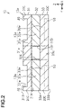
- FIG. 2 shows a section of the condenser 13 taken along a line 2-2 in FIG. 1 .
- This section is a plane orthogonal to a direction in which the working fluid C flows in the condenser 13.
- the section shown in FIG. 2 is a section in which the condenser 13 is cut by a YZ plane orthogonal to the length direction of the flow channel r2.
- FIG. 3 shows a section of the loop heat pipe 10 taken along a line 3-3 in FIG. 1 .
- This section is a section in which the condenser 13 is cut by an XZ plane extending in parallel with the flow channel r2.
- the condenser 13 has, for example, a structure in which three metal layers 31, 32, and 33 are deposited on one another.
- the condenser 13 has a structure in which the metal layer 32 serving as an inner metal layer is deposited between the metal layers 31 and 33 serving as a pair of outer metal layers.
- the inner metal layer of the condenser 13 in the present embodiment is constituted by only one metal layer 32.
- Each of the metal layers 31 to 33 is, for example, a copper (Cu) layer excellent in heat conductivity.
- the metal layers 31 to 33 are, for example, directly bonded to one another by solid-phase bonding such as diffusion bonding, pressure welding, friction welding or ultrasonic bonding.
- solid-phase bonding such as diffusion bonding, pressure welding, friction welding or ultrasonic bonding.
- the metal layers 31 to 33 are distinguished from one another by a solid line.
- an interface between adjacent ones of the metal layers 31 to 33 may disappear so that a boundary therebetween may be unclear.
- each of the metal layers 31 to 33 is not limited to the copper layer, but may be formed of a stainless steel layer, an aluminum layer, a magnesium alloy layer, or the like. Further, a material used for forming some of the deposited metal layers 31 to 33 may be different from a material used for forming the others of the metal layers 31 to 33. Thickness of each of the metal layers 31 to 33 can be, for example, set in a range of about 50 ⁇ m to 200 ⁇ m. Incidentally, some of the metal layers 31 to 33 may be set to be different in thickness from the others of the metal layers 31 to 33, or all the metal layers 31 to 33 may be set to be different in thickness from one another.
- the condenser 13 that is made up of the metal layers 31 to 33 deposited in the Z-axis direction has the flow channel 13r, and a pair of the pipe walls 13w that are provided on the opposite sides of the flow channel 13r in the Y-axis direction.
- the metal layer 32 is deposited between the metal layer 31 and the metal layer 33. An upper face of the metal layer 32 is bonded to the metal layer 31. A lower face of the metal layer 32 is bonded to the metal layer 33.
- the metal layer 32 has a through hole 32X that penetrates the metal layer 32 in the thickness direction, and a pair of pipe walls 32w that are provided on opposite sides of the through hole 32X in the Y-axis direction.
- the through hole 32X constitutes the flow channel 13r.
- the metal layer 31 is deposited on the upper face of the metal layer 32.
- the metal layer 31 has an inner face 31A (a lower face in this case) that is bonded to the metal layer 32, and an outer face 31B (an upper face in this case) that is provided on an opposite side to the inner face 31A in the thickness direction (the Z-axis direction in this case) of the metal layer 31.
- the metal layer 31 has pipe walls 31w that are provided at positions overlapping the pipe walls 32w in plan view, and an upper wall 31u that is provided at a position overlapping the flow channel 13r in plan view.
- the inner face 31A in each of the pipe walls 31w is bonded to the upper face in a corresponding one of the pipe walls 32w.
- the upper wall 31u is provided between a pair of the pipe walls 31w.
- the inner face 31A in the upper wall 31u is exposed to the flow channel 13r. In other words, the upper wall 31u constitutes the flow channel 13r.
- the metal layer 31 has one or more recesses 40 in the outer face 31B.
- the recesses 40 are provided so as not to overlap the flow channel 15, specifically the flow channel 13r, in plan view.
- the recesses 40 are provided in the outer face 31B in the pipe walls 31w.
- the recesses 40 are, for example, provided in both the pair of the pipe walls 31w.
- the recesses 40 are not provided in the outer face 31B in the upper wall 31u.
- Each of the recesses 40 is, for example, formed to be recessed from the outer face 31B of the metal layer 31 to a corresponding one of thicknesswise intermediate portions of the metal layer 31.
- Each of the recess 40 is, for example, formed to extend from the outer face 31B of the metal layer 31 to a corresponding one of thicknesswise central portions of the metal layer 31.
- the metal layer 31 has the plurality of recesses 40 that are arranged side by side along one direction (the X-axis direction in this case) of a plane direction orthogonal to the thickness direction of the metal layer 31.
- the plurality of recesses 40 are, for example, arranged side by side at predetermined intervals along the X-axis direction.
- the plurality of recesses 40 are arranged side by side along the X-axis direction on the Y-axis direction opposite sides of the flow channel 13r (specifically, the flow channel r2).
- Each of the recesses 40 for example, extends along the Y-axis direction. As shown in FIG.
- the recess 40 extends along a plane direction (the Y-axis direction in this case) of the outer face 31B of the metal layer 31.
- the recess 40 is, for example, provided to be separate from a corresponding one of outer side faces 31C of the metal layer 31.
- the recess 40 is, for example, provided to be separate from a corresponding one of inner wall faces of the through hole 32X in the Y-axis direction. That is, the recess 40 is provided only in a corresponding Y-axis direction intermediate portion of the outer face 31B in the pipe wall 31w.
- each of inner wall faces of the recesses 40 is, for example, formed to extend vertically to the outer face 31B.
- the inner wall face of the recess 40 is, for example, formed in a plane extending along the Z-axis direction.
- a bottom face of the recess 40 is, for example, formed in a plane parallel to the outer face 31B.
- the bottom face of the recess 40 is, for example, formed in the plane extending in parallel with an XY plane.
- the inner wall face of the recess 40 may be formed into a tapered shape that is widened from the bottom face side toward an opening side.
- the metal layer 33 is deposited on the lower face of the metal layer 32.
- the metal layer 33 has an inner face 33A (an upper face in this case) that is bonded to the metal layer 32, and an outer face 33B (a lower face in this case) that is provided on an opposite side to the inner face 33A in the thickness direction (the Z-axis direction in this case) of the metal layer 33.
- the metal layer 33 has pipe walls 33w that are provided at positions overlapping the pipe walls 32w in plan view, and a lower wall 33d that is provided at a position overlapping the flow channel 13r in plan view.
- the inner face 33A in each of the pipe walls 33w is bonded to the lower face in a corresponding one of the pipe walls 32w.
- the lower wall 33d is provided between a pair of the pipe walls 33w.
- the inner face 33A in the lower wall 33d is exposed to the flow channel 13r. In other words, the lower wall 33d constitutes the flow channel 13r.
- the metal layer 33 has one or more recesses 50 provided in the outer face 33B.
- the recesses 50 are provided so as not to overlap the flow channel 15, specifically the flow channel 13r, in plan view.
- the recesses 50 are provided in the outer face 33B of the pipe walls 33w.
- the recesses 50 are, for example, provided in both the pair of the pipe walls 33w.
- the recesses 50 are not provided in the outer face 33B of the lower wall 33d.
- Each of the recesses 50 is, for example, formed to be recessed from the outer face 33B of the metal layer 33 to a corresponding one of thicknesswise intermediate portions of the metal layer 33.
- Each of the recesses 50 is, for example, formed to extend from the outer face 33B of the metal layer 33 to a corresponding one of thicknesswise central portions of the metal layer 33.
- the metal layer 33 has the recesses 50 that are arranged side by side along one direction (the X-axis direction in this case) of the plane direction orthogonal to the thickness direction of the metal layer 33.
- the recesses 50 are, for example, arranged side by side along the X-axis direction at predetermined intervals.
- Each of the recesses 50 is provided so as not to overlap any one of the recesses 40 in plan view.
- the recess 50 is, for example, provided so as not to overlap any entire one of the recesses 40 in plan view.
- the recesses 50 are arranged side by side along the X-axis direction at enough intervals not overlapping the recesses 40.
- a width dimension of each of the recesses 50 along the X-axis direction is, for example, equal to a width dimension of each of the recesses 40 along the X-axis direction.
- an interval (distance) between two of the recesses 50 adjacent in the X-axis direction is larger than the width dimension of each recess 40, 50.
- the recesses 50 are arranged side by side along the X-axis direction on the Y-axis direction opposite sides of the flow channel 13r (specifically, the flow channel r2).
- Each of the recesses 50 for example, extends along the Y-axis direction.
- the recess 50 for example, extends in parallel with the recesses 40.
- a length dimension of the recess 50 along the Y-axis direction is, for example, equal to a Y-axis direction length dimension of the recess 40 which is adjacent to the recess 50 in the X-axis direction.
- each of the recesses 50 is, for example, provided to be separate from a corresponding one of outer side faces 33C of the metal layer 33.
- the recess 50 is, for example, provided to be separate from a corresponding one of the inner wall faces of the through hole 32X in the Y-axis direction. That is, the recess 50 is provided in only a corresponding Y-axis direction intermediate portion of the outer face 33B in the pipe wall 33w.
- each of inner wall faces of the recesses 50 is, for example, formed to extend vertically to the outer face 33B.
- the inner wall face of the recess 50 is, for example, formed in a plane extending along the Z-axis direction.
- Abottom face of the recess 50 is, for example, formed in a plane parallel to the outer face 33B.
- the bottom face of the recess 50 is, for example, formed in the plane extending parallel to the XY plane.
- the inner wall face of the recess 50 may be formed into a tapered shape that is widened from the bottom face side toward an opening side.
- the flow channel 13r is constituted by the through hole 32X of the metal layer 32.
- the flow channel 13r is formed by a space surrounded by the inner wall faces of the through hole 32X, the inner face 31A of the upper wall 31u, and the inner face 33A of the lower wall 33d.
- Each of the pipe walls 13w is, for example, constituted by the pipe wall 31w of the metal layer 31, the pipe wall 32w of the metal layer 32, and the pipe wall 33w of the metal layer 33.
- the vapor pipe 12 is formed by the three metal layers 31 to 33 stacked on one another in a manner similar to or the same as the condenser 13.
- the through hole 32Y that penetrates the metal layer 32, that is an inner metal layer, in the thickness direction is formed so that the flow channel 12r is formed.
- the vapor pipe 12 has the pair of the pipe walls 12w provided on the opposite sides in the width direction (the X-axis direction in this case) that is orthogonal to the length direction (the Y-axis direction in this case) of the vapor pipe 12.
- no hole or groove is formed in each of the pipe walls 12w.
- the liquid pipe 14 is formed by the three metal layers 31 to 33 stacked on one another in a manner similar to or the same as the condenser 13.
- a through hole 32Z that penetrates the metal layer 32, that is the inner metal layer, in the thickness direction is formed so that the flow channel 14r is formed.
- the liquid pipe 14 has the pair of pipe walls 14w provided on the opposite sides in the width direction (the X-axis direction in this case) that is orthogonal to the length direction (the Y-axis direction in this case) of the liquid pipe 14.
- no hole or groove is formed in each of the pipe walls 14w.
- the liquid pipe 14 may, for example, have a porous body.
- the porous body is, for example, configured to have first bottomed holes recessed from the upper face of the metal layer 32 that is the inner metal layer, second bottomed holes recessed from the lower face of the metal layer 32, and pores formed by partial communication between the first bottomed holes and the second bottomed holes.
- the porous body guides the working fluid C liquefied in the condenser 13 to the evaporator 11 (see FIG. 1 ) by capillary force generated in the porous body.
- an injection port for injecting the working fluid C is provided in the liquid pipe 14.
- the injection port is sealed by a sealing material so that the inside of the loop heat pipe 10 is kept airtight.
- the evaporator 11 shown in FIG. 1 is formed by the three metal layers 31 to 33 (see FIG. 3 ) stacked on one another in a manner similar to or the same as the vapor pipe 12, the condenser 13 and the liquid pipe 14 shown in FIG. 3 .
- the evaporator 11 may, for example, have a porous body in a manner similar to or the same as the liquid pipe 14.
- the porous body provided in the evaporator 11 is formed into a comb teeth shape. Inside the evaporator 11, a space is formed in a region where the porous body is not provided.
- the loop heat pipe 10 has a configuration in which the three metal layers 31 to 33 (see FIG. 2 and FIG. 3 ) are stacked on one another.
- the number of the stacked metal layers is not limited to three, but can be set at four or more.
- the loop heat pipe 10 has the evaporator 11 for vaporizing a working fluid C, the vapor pipe 12 for guiding the vaporized working fluid (i.e. vapor Cv) to flow into the condenser 13, the condenser 13 for liquefying the vapor Cv, and the liquid pipe 14 for guiding the liquefied working fluid C to flow into the evaporator 11.
- the vapor Cv generated in the evaporator 11 by heat of the heating component is guided to the condenser 13 through the vapor pipe 12.
- the vapor Cv is liquefied in the condenser 13. That is, the heat generated in the heating component is dissipated in the condenser 13. As a result, the heating component is cooled so that an increase in temperature of the heating component can be suppressed.
- the recesses 40 are provided in the outer face 31B of the metal layer 31, that is an outer metal layer, and the recesses 50 are provided in the outer face 33B of the metal layer 33, that is an outer metal layer.
- a surface area in the outer face 31B, 33B of the metal layer 31, 33 can be increased in comparison with a case where the recesses 40, 50 are not provided. Therefore, the surface area that can contact outside air in the metal layer 31, 33 can be increased, and an amount of heat exchange with the outside air can be increased, in comparison with the case where the recesses 40, 50 are not provided.
- efficiency of the heat exchange i.e. heat dissipation performance, in the condenser 13 can be improved.
- the metal layer 31 is an example of a first outer metal layer
- the metal layer 32 is an example of the inner metal layer
- the metal layer 33 is an example of a second outer metal layer.
- the inner face 31A is an example of a first inner face
- the outer face 31B is an example of a first outer face
- the inner face 33A is an example of a second inner face
- the outer face 33B is an example of a second outer face.
- the recess 40 is an example of a first recess
- the recess 50 is an example of a second recess.
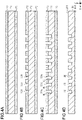
- a flat plate-like metal sheet 71 is prepared.
- the metal sheet 71 is a member that will ultimately become a metal layer 31 (see FIG. 3 ).
- the metal sheet 71 is, for example, made of copper, stainless steel, aluminum, a magnesium alloy, or the like. Thickness of the metal sheet 71 can be, for example, set in a range of about 50 ⁇ m to 200 ⁇ m.
- a resist layer 72 is formed on an upper face of the metal sheet 71, and a resist layer 73 is formed on a lower face of the metal sheet 71.
- a photosensitive dry film resist or the like, can be used as each of the resist layers 72 and 73.
- the resist layer 72 is exposed to light and developed so that opening portions 72X for selectively exposing the upper face of the metal sheet 71 are formed in the resist layer 72.
- the opening portions 72X are formed to correspond to recesses 40 shown in FIG. 3 .
- the metal sheet 71 exposed inside the opening portions 72X is etched from the upper face side of the metal sheet 71.
- the recesses 40 are formed in the upper face of the metal sheet 71.
- the recesses 40 can be, for example, formed by wet etching applied to the metal sheet 71 with the resist layers 72 and 73 as etching masks.
- a ferric chloride aqueous solution or a cupric chloride aqueous solution can be used as an etching solution.
- the resist layers 72 and 73 are stripped off by a stripping solution.
- the metal layer 31 having the recesses 40 in an outer face 31B can be formed, as shown in FIG. 4D .
- a flat plate-like metal sheet 74 is prepared.
- the metal sheet 74 is a member that will ultimately become a metal layer 32 (see FIG. 3 ).
- the metal sheet 74 is, for example, made of copper, stainless steel, aluminum, a magnesium alloy, or the like. Thickness of the metal sheet 74 can be, for example, set in a range of about 50 ⁇ m to 200 ⁇ m.
- a resist layer 75 is formed on an upper face of the metal sheet 74, and a resist layer 76 is formed on a lower face of the metal sheet 74.
- a photosensitive dry film resist or the like, can be used as each of the resist layers 75 and 76.
- the resist layer 75 is exposed to light and developed so that openings portions 75Y and 75Z for selectively exposing the upper face of the metal sheet 74 are formed in the resist layer 75.
- the resist layer 76 is exposed to light and developed so that opening portions 76Y and 76Z for selectively exposing the lower face of the metal sheet 74 are formed in the resist layer 76.
- the opening portions 75Y and 76Y are formed to correspond to a through hole 32Y shown in FIG. 3 .
- the opening portions 75Z and 76Z are formed to correspond to a through hole 32Z shown in FIG. 3 .
- the opening portion 75Y and the opening portion 76Y are provided at positions overlapping each other in plan view.
- the opening portion 75Z and the opening portion 76Z are provided at positions overlapping each other in plan view.
- the metal sheet 74 exposed from the resist layers 75 and 76 is etched from the opposite upper and lower faces of the metal sheet 74. Due to the opening portions 75Y and 76Y, the through hole 32Y is formed in the metal sheet 74. Moreover, due to the opening portions 75Z and 76Z, the through hole 32Z is formed in the metal sheet 74.
- the through holes 32Y and 32Z can be, for example, formed by wet etching applied to the metal sheet 74 with the resist layers 75 and 76 as etching masks. When copper is used as the material of the metal sheet 74, a ferric chloride aqueous solution or a cupric chloride aqueous solution can be used as an etching solution.
- a through hole 32X (see FIG. 2 ) can be formed in a manner similar to or the same as the through holes 32Y and 32Z.
- the resist layers 75 and 76 are stripped off by a stripping solution.
- the metal layer 32 having the through holes 32Y and 32Z and the through hole 32X can be formed, as shown in FIG. 5D .
- a metal layer 33 having recesses 50 in an outer face 33B is formed by a method similar to or the same as the steps shown in FIGS. 4A to 4D .
- the metal layer 32 is disposed between the metal layer 31 and the metal layer 33.
- the metal layers 31 to 33 stacked on one another are pressed while being heated at a predetermined temperature (e.g. about 900°C) so that the metal layers 31 to 33 are bonded to one another by solid-phase bonding.
- a predetermined temperature e.g. about 900°C
- the metal layers 31, 32, and 33 adjacent in the stacking direction are directly bonded.
- an inner face 31A the lower face in this case
- the through hole 32X see FIG. 2
- the recesses 50 are not formed in portions overlapping the recesses 40 in plan view in the metal layers 31 to 33.
- a structure body in which the metal layers 31, 32 and 33 are stacked on one another is formed.
- a loop heat pipe 10 having an evaporator 11, a vapor pipe 12, a condenser 13 and a liquid pipe 14 as shown in FIG. 1 is formed.
- air inside the liquid pipe 14 is then exhausted by a vacuum pump or the like, a working fluid C is injected into the liquid pipe 14 from a not-shown injection port, and then, the injection port is sealed.
- each of the recesses 40, 50 in the aforementioned embodiment is not particularly limited.
- the inner face of the recess 40, 50 may be formed into an arc-shaped curved face in sectional view.
- the inner face of the recess 40, 50 may be formed into a concave shape that is a semi-circular shape or a semi-elliptical shape in section.
- the "semi-circular shape" includes not only a semi-circle bisecting a perfect circle, but also, for example, a circular shape longer or shorter in arc than the semi-circle.
- the "semi-elliptical shape" includes not only a semi-ellipse bisecting an ellipse, but also, for example, an elliptical shape longer or shorter in arc than the semi-ellipse.
- the inner face of the recess 40, 50 in this modification is formed into the semi-elliptical shape in section.
- the radius of curvature of the bottom face of the recess 40, 50 and the radius of curvature of each of the inner wall faces of the recess 40, 50 may be equal to each other or may be different from each other.
- the recesses 50 are provided so as not to overlap the recesses 40 in plan view.
- the recesses 50 are not limited thereto.
- the recesses 50 may be provided so as to partially overlap the recesses 40 in plan view. That is, portions of the recesses 50 in this modification overlap portions of the recesses 40 in plan view.
- each of the recesses 40 is formed to be recessed from the outer face 31B of the metal layer 31 to a corresponding one of the thicknesswise central portions of the metal layer 31.
- the depth of the recess 40 is not limited thereto.
- the recess 40 may be formed to penetrate the metal layer 31 in the thickness direction. That is, the recess 40 may be formed into a through hole. According to this configuration, as the depth of the recess 40 is larger, each of the inner wall faces of the recess 40 exposed to the outside is larger accordingly. Therefore, the surface area that can contact the outside air in the metal layer 31 can be increased. Thus, heat dissipation performance in the condenser 13 can be improved.
- the recess 40 constituted by the through hole is, for example, also provided to be separate from the corresponding outer side face 31C of the metal layer 31. Moreover, the recess 40 constituted by the through hole is, for example, provided to be separate from the corresponding inner wall face of the through hole 32X in the Y-axis direction.
- each of the recesses 40 is formed into the through hole, the handleability of the metal layer 31 as a single unit during the manufacturing process may be lowered. Therefore, it is preferable that the recess 40 is formed to penetrate the metal layer 31 in the thickness direction within a range in which desired handleability can be maintained. For example, only some of the plurality of recesses 40 may be formed to penetrate the metal layer 31 in the thickness direction.
- each of the recesses 50 is formed from the outer face 33B of the metal layer 33 to a corresponding one of the thicknesswise central portions of the metal layer 33.
- the depth of the recess 50 is not limited thereto.
- the recesses 50 may be formed to penetrate the metal layer 33 in the thickness direction. That is, each of the recesses 50 may be formed into a through hole. According to this configuration, as the depth of the recess 50 is larger, each of the inner wall faces of the recess 50 exposed to the outside is larger accordingly. Therefore, the surface area that can contact the outside air in the metal layer 33 can be increased. Thus, the heat dissipation performance in the condenser 13 can be improved.
- the recess 50 constituted by the through hole is, for example, also provided to be separate from the corresponding outer side face 33C of the metal layer 33. Moreover, the recess 50 constituted by the through hole is, for example, provided to be separate from the corresponding inner wall face of the through hole 32X in the Y-axis direction.
- each of the recesses 50 is formed into the through hole, handleability of the metal layer 33 as a single unit during the manufacturing process is lowered easily. Therefore, it is preferable that the recess 50 is formed to penetrate the metal layer 33 in the thickness direction within a range in which desired handleability can be maintained.
- the recesses 40, 50 are provided at positions separate from the outer side faces of the pipe walls 13w.
- the recesses 40, 50 are not limited thereto.
- the recesses 40, 50 may be formed to extend to the outer side faces of the pipe walls 13w.
- Each of the recesses 40, 50 in this case is, for example, formed to be open in the Y-axis direction. That is, the recess 40, 50 in this modification is formed in the shape of a notch.
- the planar shape of the recess 40, 50 in the aforementioned embodiment is not particularly limited.
- the recess 40, 50 can be formed into any shape in plan view.
- the planar shape of the recess 40, 50 can be appropriately changed in accordance with the shape of the condenser 13 as a whole, the direction of flow of the outside air, etc.
- each of the recesses 40, 50 may be formed to extend along the X-axis direction in the XY plane.
- the plurality of recesses 40 are arranged side by side along the Y-axis direction
- the plurality of recesses 50 are arranged side by side along the Y-axis direction.
- each of the recesses 40, 50 may be formed to extend in a first direction crossing both the X-axis direction and the Y-axis direction in the XY plane.
- the plurality of recesses 40 are arranged side by side along a second direction orthogonal to the first direction in the XY plane, and the plurality of recesses 50 are arranged side by side along the second direction.
- each of the recesses 40, 50 may be formed into the shape of a circle in plan view.
- the plurality of recesses 40 are provided in the form of a matrix in the XY plane
- the plurality of recesses 50 are provided in the form of a matrix in the XY plane.
- the shape of the flow channel 13r in the condenser 13 is not particularly limited.
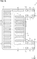
- the flow channel 13r may be formed into a shape having a meandering portion r4 that meanders in the XY plane.
- the flow channel 13r in this modification has a flow channel r1 extending in the Y-axis direction, the meandering portion r4 extending in the X-axis direction from an end portion of the flow channel r1 while meandering, and a flow channel r3 extending in the Y-axis direction from an end portion of the meandering portion r4.
- the recesses 40, 50 are provided so as not to overlap the flow channel 13r in plan view.
- the recesses 40, 50 are provided in the pipe walls 13w of the condenser 13.
- the recesses 40, 50 are not limited thereto.
- the recesses 40, 50 may be provided in the pipe walls 12w of the vapor pipe 12.
- the recesses 40, 50 in this case are provided so as not to overlap the flow channel 15, specifically the flow channel 12r, in plan view.
- the recesses 40, 50 may be provided in the pipe walls 14w of the liquid pipe 14.
- the recesses 40, 50 in this case are provided so as not to overlap the flow channel 15, specifically the flow channel 14r, in plan view.
- the recesses 40, 50 in the pipe walls 13w of the condenser 13 may be omitted.
- the plurality of recesses 40 may be formed into different shapes from one another.
- the plurality of recesses 50 may be formed into different shapes from one another.
- the recesses 40 and the recesses 50 may be formed into different shapes from each other.
- the recesses 50 may be omitted.
- the inner metal layer is constituted by only the single metal layer 32. That is, the inner metal layer is formed into a single layer structure.
- the inner metal layer is not limited thereto.
- the inner metal layer may be formed into a laminated structure in which a plurality of metal layers are stacked on one another.
- the inner metal layer in this case is constituted by the plurality of metal layers stacked between the metal layer 31 and the metal layer 33.
Landscapes
- Engineering & Computer Science (AREA)
- Life Sciences & Earth Sciences (AREA)
- Sustainable Development (AREA)
- Physics & Mathematics (AREA)
- Thermal Sciences (AREA)
- Mechanical Engineering (AREA)
- General Engineering & Computer Science (AREA)
- Cooling Or The Like Of Semiconductors Or Solid State Devices (AREA)
Abstract
Description
- The present disclosure relates to a loop heat pipe.
- In the background art, heat pipes each of which transports heat using a phase change of a working fluid have been proposed as devices for cooling heating components of semiconductor devices (such as CPUs) mounted on electronic apparatuses (e.g. see
Japanese Patent Nos. 6291000 6400240 - As an example of such a heat pipe, there has been known a loop heat pipe including an evaporator that vaporizes a working fluid by heat of a heating component, and a condenser that cools and liquefies the vaporized working fluid. In the loop heat pipe, the evaporator and the condenser are connected to each other through a liquid pipe and a vapor pipe, that form a loop-like flow channel. In the loop heat pipe, the working fluid flows through the loop-like flow channel in one direction.
- By the way, an improvement in heat dissipation performance of the aforementioned loop heat pipe has been desired, but there is still room for improvement in this respect.
- A certain embodiment provides a loop heat pipe. The loop heat pipe includes: an evaporator configured to vaporize a working fluid; a condenser configured to liquefy the working fluid; a liquid pipe that connects the evaporator and the condenser to each other; and a vapor pipe that connects the evaporator and the condenser to each other. The condenser includes: a first outer metal layer; a second outer metal layer; and an inner metal layer that is provided between the first outer metal layer and the second outer metal layer, and having a flow channel through which the working fluid flows. The first outer metal layer includes: a first inner face that contacts the inner metal layer; a first outer face opposite to the first inner face in a thickness direction of the first outer metal layer; and a first recess that is provided in the first outer face so as not to overlap the flow channel in plan view.
- A certain embodiment provides a loop heat pipe. The loop heat pipe includes: an evaporator configured to vaporize a working fluid; a condenser configured to liquefy the working fluid; a liquid pipe that connects the evaporator and the condenser to each other; a vapor pipe that connects the evaporator and the condenser to each other; and a flow channel that is provided in the liquid pipe, the vapor pipe and the condenser to allow the working fluid to flow therethrough. At least one of the condenser, the liquid pipe and the vapor pipe includes: a first outer metal layer; a second outer metal layer; and an inner metal layer that is provided between the first outer metal layer and the second outer metal layer. The first outer metal layer includes: a first inner face that contacts the inner metal layer; a first outer face opposite side to the first inner face in a thickness direction of the first metal layer; and a first recess that is provided in the first outer face so as not to overlap the flow channel in plan view.
- In the following, embodiments are described with reference to the drawings without being limited thereto.
-
FIG. 1 is a schematic plan view showing a loop heat pipe according to an embodiment; -
FIG. 2 is a schematic sectional view (sectional view taken along a line 2-2 inFIG. 1 ) showing a condenser according to the embodiment; -
FIG. 3 is a schematic sectional view (sectional view taken along a line 3-3 inFIG. 1 ) showing the loop heat pipe according to the embodiment; -
FIGS. 4A to 4D are schematic sectional views showing a method for manufacturing the loop heat pipe according to the embodiment; -
FIGS. 5A to 5D are schematic sectional views showing the method for manufacturing the loop heat pipe according to the embodiment; -
FIGS. 6A and 6B are schematic sectional views showing the method for manufacturing the loop heat pipe according to the embodiment; -
FIG. 7 is a schematic sectional view showing a loop heat pipe according to a modification; -
FIG. 8 is a schematic sectional view showing a loop heat pipe according to a modification; -
FIG. 9 is a schematic sectional view showing a loop heat pipe according to a modification; -
FIG. 10 is a schematic plan view showing a loop heat pipe according to a modification; -
FIG. 11 is a schematic plan view showing a loop heat pipe according to a modification; -
FIG. 12 is a schematic plan view showing a loop heat pipe according to a modification; -
FIG. 13 is a schematic plan view showing a loop heat pipe according to a modification; -
FIG. 14 is a schematic plan view showing a loop heat pipe according to a modification; and -
FIG. 15 is a schematic plan view showing a loop heat pipe according to a modification. - An embodiment will be described below with reference to the accompanying drawings. Incidentally, for convenience, the accompanying drawings may show each characteristic portion in an enlarged manner in order to make the characteristic easy to understand, and a dimensional ratio among constituent elements may be different among the drawings. Further, in order to make sectional structures of members easy to understand in sectional view, some of the members to be hatched will be not hatched but drawn in a satin pattern. In each drawing, X-, Y- and Z-axes that are orthogonal to one another are shown. In the following description, for convenience, a direction extending along the X-axis will be referred to as X-axis direction, a direction extending along the Y-axis will be referred to as Y-axis direction, and a direction extending along the Z-axis will be referred to as Z-axis direction. Incidentally, in the present specification, a "plan view" will be referred to as a view of an object from a vertical direction (the Z-axis direction in this case) of
FIG. 2 etc., and a "planar shape" will be referred to as a shape of the object viewed from the vertical direction ofFIG. 2 etc. - A
loop heat pipe 10 as shown inFIG. 1 is, for example, housed in a mobile type electronic apparatus M1 such as a smartphone or a tablet terminal. Theloop heat pipe 10 has anevaporator 11, avapor pipe 12, acondenser 13, and aliquid pipe 14. - The
evaporator 11 and thecondenser 13 are connected to each other by thevapor pipe 12 and theliquid pipe 14. Theevaporator 11 is configured to vaporize a working fluid C to generate vapor Cv. The vapor Cv generated in theevaporator 11 flows to thecondenser 13 through thevapor pipe 12. Thecondenser 13 is configured to liquefy the vapor Cv of the working fluid C. The liquefied working fluid C flows to theevaporator 11 through theliquid pipe 14. Thevapor pipe 12 and theliquid pipe 14 form a loop-like flow channel 15 which allows the working fluid C or the vapor Cv to flow therethrough. - The
vapor pipe 12 is, for example, formed into a long tubular body. Theliquid pipe 14 is, for example, formed into a long tubular body. In the present embodiment, thevapor pipe 12 and theliquid pipe 14 are, for example, equal in dimension in a length direction (i.e. length) to each other. Incidentally, the length of thevapor pipe 12 and the length of theliquid pipe 14 may be different from each other. For example, the length of thevapor pipe 12 may be shorter than the length of theliquid pipe 14. Here, the "length direction" of theevaporator 11, thevapor pipe 12, thecondenser 13, and theliquid pipe 14 in the present specification is a direction consistent with a direction (see arrows inFIG. 1 ) in which the working fluid C or the vapor Cv in each member flows. In addition, in this specification, the term "equal" includes a case where objects to be compared are exactly equal, and a case where the objects are slightly different due to a dimensional tolerance etc. - The
evaporator 11 is fixed in close contact with a not-shown heating component. The working fluid C in theevaporator 11 is vaporized by heat generated in the heating component, so that the vapor Cv is generated. Incidentally, a thermal interface material (TIM) may be interposed between theevaporator 11 and the heating component. The TIM reduces thermal contact resistance between the heating component and theevaporator 11 to make the heat be conducted from the heating component to theevaporator 11 smoothly. - The
vapor pipe 12 has, for example, a pair ofpipe walls 12w that are provided on opposite sides in a width direction orthogonal to the length direction of thevapor pipe 12 in plan view, and aflow channel 12r that is provided between the pair ofpipe walls 12w. Theflow channel 12r communicates with an internal space of theevaporator 11. Theflow channel 12r is a part of the loop-like flow channel 15. The vapor Cv generated in theevaporator 11 is guided to thecondenser 13 through thevapor pipe 12. - The
condenser 13 has, for example, aheat dissipating plate 13p whose area has been enlarged for heat dissipation, and aflow channel 13r that is provided inside theheat dissipating plate 13p. Theflow channel 13r has a flow channel r1 that communicates with theflow channel 12r and extends along the Y-axis direction, a flow channel r2 that is bent from the flow channel r1 and extends along the X-axis direction, and a flow channel r3 that is bent from the flow channel r2 and extends along the Y-direction. Theflow channel 13r (the flow channels r1 to r3) is a part of the loop-like flow channel 15. Thecondenser 13 haspipe walls 13w provided on opposite sides in a direction orthogonal to the length direction of theflow channel 13r, i.e. the flow channels r1 to r3. The vapor Cv guided through thevapor pipe 12 is liquefied in thecondenser 13. - The
liquid pipe 14 has, for example, a pair ofpipe walls 14w that are provided on opposite sides in a width direction orthogonal to the length direction of theliquid pipe 14 in plan view, and aflow channel 14r that is provided between the pair ofpipe walls 14w. Theflow channel 14r communicates with theflow channel 13r (specifically the flow channel r3) of thecondenser 13, and communicates with the internal space of theevaporator 11. Theflow channel 14r is a part of the loop-like flow channel 15. The working fluid C liquefied in thecondenser 13 is guided to theevaporator 11 through theliquid pipe 14. - In the
loop heat pipe 10, the heat generated in the heating component moves to thecondenser 13 to be dissipated in thecondenser 13. Thus, the heating component is cooled so that an increase in temperature of the heating component can be suppressed. - It is preferable that a fluid high in vapor pressure and large in latent heat of vaporization is used as the working fluid C. By use of such a working fluid C, the heating component can be efficiently cooled by the latent heat of vaporization. For example, ammonia, water, chlorofluorocarbon, alcohol, acetone, or the like, can be used as the working fluid C.
-
FIG. 2 shows a section of thecondenser 13 taken along a line 2-2 inFIG. 1 . This section is a plane orthogonal to a direction in which the working fluid C flows in thecondenser 13. Specifically, the section shown inFIG. 2 is a section in which thecondenser 13 is cut by a YZ plane orthogonal to the length direction of the flow channel r2.FIG. 3 shows a section of theloop heat pipe 10 taken along a line 3-3 inFIG. 1 . This section is a section in which thecondenser 13 is cut by an XZ plane extending in parallel with the flow channel r2. - As shown in
FIG. 2 , thecondenser 13 has, for example, a structure in which threemetal layers condenser 13 has a structure in which themetal layer 32 serving as an inner metal layer is deposited between the metal layers 31 and 33 serving as a pair of outer metal layers. The inner metal layer of thecondenser 13 in the present embodiment is constituted by only onemetal layer 32. - Each of the metal layers 31 to 33 is, for example, a copper (Cu) layer excellent in heat conductivity. The metal layers 31 to 33 are, for example, directly bonded to one another by solid-phase bonding such as diffusion bonding, pressure welding, friction welding or ultrasonic bonding. Incidentally, to make it easy to understand in
FIG. 2 , the metal layers 31 to 33 are distinguished from one another by a solid line. When, for example, the metal layers 31 to 33 are integrated by the diffusion bonding, an interface between adjacent ones of the metal layers 31 to 33 may disappear so that a boundary therebetween may be unclear. Here, the solid-phase bonding is a method in which objects to be bonded are not melted into each other but softened by heat in a solid-phase (solid) state, and then plastically deformed by further heat to be bonded to each other. Incidentally, each of the metal layers 31 to 33 is not limited to the copper layer, but may be formed of a stainless steel layer, an aluminum layer, a magnesium alloy layer, or the like. Further, a material used for forming some of the depositedmetal layers 31 to 33 may be different from a material used for forming the others of the metal layers 31 to 33. Thickness of each of the metal layers 31 to 33 can be, for example, set in a range of about 50 µm to 200 µm. Incidentally, some of the metal layers 31 to 33 may be set to be different in thickness from the others of the metal layers 31 to 33, or all the metal layers 31 to 33 may be set to be different in thickness from one another. - The
condenser 13 that is made up of the metal layers 31 to 33 deposited in the Z-axis direction has theflow channel 13r, and a pair of thepipe walls 13w that are provided on the opposite sides of theflow channel 13r in the Y-axis direction. - The
metal layer 32 is deposited between themetal layer 31 and themetal layer 33. An upper face of themetal layer 32 is bonded to themetal layer 31. A lower face of themetal layer 32 is bonded to themetal layer 33. Themetal layer 32 has a throughhole 32X that penetrates themetal layer 32 in the thickness direction, and a pair ofpipe walls 32w that are provided on opposite sides of the throughhole 32X in the Y-axis direction. The throughhole 32X constitutes theflow channel 13r. - The
metal layer 31 is deposited on the upper face of themetal layer 32. Themetal layer 31 has aninner face 31A (a lower face in this case) that is bonded to themetal layer 32, and anouter face 31B (an upper face in this case) that is provided on an opposite side to theinner face 31A in the thickness direction (the Z-axis direction in this case) of themetal layer 31. Themetal layer 31 haspipe walls 31w that are provided at positions overlapping thepipe walls 32w in plan view, and anupper wall 31u that is provided at a position overlapping theflow channel 13r in plan view. Theinner face 31A in each of thepipe walls 31w is bonded to the upper face in a corresponding one of thepipe walls 32w. Theupper wall 31u is provided between a pair of thepipe walls 31w. Theinner face 31A in theupper wall 31u is exposed to theflow channel 13r. In other words, theupper wall 31u constitutes theflow channel 13r. - The
metal layer 31 has one ormore recesses 40 in theouter face 31B. Therecesses 40 are provided so as not to overlap theflow channel 15, specifically theflow channel 13r, in plan view. Therecesses 40 are provided in theouter face 31B in thepipe walls 31w. Therecesses 40 are, for example, provided in both the pair of thepipe walls 31w. Therecesses 40 are not provided in theouter face 31B in theupper wall 31u. Each of therecesses 40 is, for example, formed to be recessed from theouter face 31B of themetal layer 31 to a corresponding one of thicknesswise intermediate portions of themetal layer 31. Each of therecess 40 is, for example, formed to extend from theouter face 31B of themetal layer 31 to a corresponding one of thicknesswise central portions of themetal layer 31. - As shown in
FIG. 3 , themetal layer 31 has the plurality ofrecesses 40 that are arranged side by side along one direction (the X-axis direction in this case) of a plane direction orthogonal to the thickness direction of themetal layer 31. The plurality ofrecesses 40 are, for example, arranged side by side at predetermined intervals along the X-axis direction. As shown inFIG. 1 , in thecondenser 13, the plurality ofrecesses 40 are arranged side by side along the X-axis direction on the Y-axis direction opposite sides of theflow channel 13r (specifically, the flow channel r2). Each of therecesses 40, for example, extends along the Y-axis direction. As shown inFIG. 2 , therecess 40 extends along a plane direction (the Y-axis direction in this case) of theouter face 31B of themetal layer 31. Therecess 40 is, for example, provided to be separate from a corresponding one of outer side faces 31C of themetal layer 31. In addition, therecess 40 is, for example, provided to be separate from a corresponding one of inner wall faces of the throughhole 32X in the Y-axis direction. That is, therecess 40 is provided only in a corresponding Y-axis direction intermediate portion of theouter face 31B in thepipe wall 31w. - As shown in
FIG. 2 andFIG. 3 , each of inner wall faces of therecesses 40 is, for example, formed to extend vertically to theouter face 31B. The inner wall face of therecess 40 is, for example, formed in a plane extending along the Z-axis direction. A bottom face of therecess 40 is, for example, formed in a plane parallel to theouter face 31B. The bottom face of therecess 40 is, for example, formed in the plane extending in parallel with an XY plane. Incidentally, the inner wall face of therecess 40 may be formed into a tapered shape that is widened from the bottom face side toward an opening side. - As shown in
FIG. 2 , themetal layer 33 is deposited on the lower face of themetal layer 32. Themetal layer 33 has aninner face 33A (an upper face in this case) that is bonded to themetal layer 32, and anouter face 33B (a lower face in this case) that is provided on an opposite side to theinner face 33A in the thickness direction (the Z-axis direction in this case) of themetal layer 33. Themetal layer 33 haspipe walls 33w that are provided at positions overlapping thepipe walls 32w in plan view, and alower wall 33d that is provided at a position overlapping theflow channel 13r in plan view. Theinner face 33A in each of thepipe walls 33w is bonded to the lower face in a corresponding one of thepipe walls 32w. Thelower wall 33d is provided between a pair of thepipe walls 33w. Theinner face 33A in thelower wall 33d is exposed to theflow channel 13r. In other words, thelower wall 33d constitutes theflow channel 13r. - The
metal layer 33 has one ormore recesses 50 provided in theouter face 33B. Therecesses 50 are provided so as not to overlap theflow channel 15, specifically theflow channel 13r, in plan view. Therecesses 50 are provided in theouter face 33B of thepipe walls 33w. Therecesses 50 are, for example, provided in both the pair of thepipe walls 33w. Therecesses 50 are not provided in theouter face 33B of thelower wall 33d. Each of therecesses 50 is, for example, formed to be recessed from theouter face 33B of themetal layer 33 to a corresponding one of thicknesswise intermediate portions of themetal layer 33. Each of therecesses 50 is, for example, formed to extend from theouter face 33B of themetal layer 33 to a corresponding one of thicknesswise central portions of themetal layer 33. - As shown in
FIG. 3 , themetal layer 33 has therecesses 50 that are arranged side by side along one direction (the X-axis direction in this case) of the plane direction orthogonal to the thickness direction of themetal layer 33. Therecesses 50 are, for example, arranged side by side along the X-axis direction at predetermined intervals. Each of therecesses 50 is provided so as not to overlap any one of therecesses 40 in plan view. Therecess 50 is, for example, provided so as not to overlap any entire one of therecesses 40 in plan view. Therecesses 50 are arranged side by side along the X-axis direction at enough intervals not overlapping therecesses 40. A width dimension of each of therecesses 50 along the X-axis direction is, for example, equal to a width dimension of each of therecesses 40 along the X-axis direction. For example, an interval (distance) between two of therecesses 50 adjacent in the X-axis direction is larger than the width dimension of eachrecess - As shown in
FIG. 1 , in thecondenser 13, therecesses 50 are arranged side by side along the X-axis direction on the Y-axis direction opposite sides of theflow channel 13r (specifically, the flow channel r2). Each of therecesses 50, for example, extends along the Y-axis direction. Therecess 50, for example, extends in parallel with therecesses 40. A length dimension of therecess 50 along the Y-axis direction is, for example, equal to a Y-axis direction length dimension of therecess 40 which is adjacent to therecess 50 in the X-axis direction. - As shown in
FIG. 2 , each of therecesses 50 is, for example, provided to be separate from a corresponding one of outer side faces 33C of themetal layer 33. In addition, therecess 50 is, for example, provided to be separate from a corresponding one of the inner wall faces of the throughhole 32X in the Y-axis direction. That is, therecess 50 is provided in only a corresponding Y-axis direction intermediate portion of theouter face 33B in thepipe wall 33w. - As shown in
FIG. 2 andFIG. 3 , each of inner wall faces of therecesses 50 is, for example, formed to extend vertically to theouter face 33B. The inner wall face of therecess 50 is, for example, formed in a plane extending along the Z-axis direction. Abottom face of therecess 50 is, for example, formed in a plane parallel to theouter face 33B. The bottom face of therecess 50 is, for example, formed in the plane extending parallel to the XY plane. Incidentally, the inner wall face of therecess 50 may be formed into a tapered shape that is widened from the bottom face side toward an opening side. - As shown in
FIG. 2 , theflow channel 13r is constituted by the throughhole 32X of themetal layer 32. Theflow channel 13r is formed by a space surrounded by the inner wall faces of the throughhole 32X, theinner face 31A of theupper wall 31u, and theinner face 33A of thelower wall 33d. - Each of the
pipe walls 13w is, for example, constituted by thepipe wall 31w of themetal layer 31, thepipe wall 32w of themetal layer 32, and thepipe wall 33w of themetal layer 33. - As shown in
FIG. 3 , thevapor pipe 12 is formed by the threemetal layers 31 to 33 stacked on one another in a manner similar to or the same as thecondenser 13. For example, in thevapor pipe 12, the throughhole 32Y that penetrates themetal layer 32, that is an inner metal layer, in the thickness direction is formed so that theflow channel 12r is formed. Thevapor pipe 12 has the pair of thepipe walls 12w provided on the opposite sides in the width direction (the X-axis direction in this case) that is orthogonal to the length direction (the Y-axis direction in this case) of thevapor pipe 12. For example, no hole or groove is formed in each of thepipe walls 12w. - The
liquid pipe 14 is formed by the threemetal layers 31 to 33 stacked on one another in a manner similar to or the same as thecondenser 13. In theliquid pipe 14, a throughhole 32Z that penetrates themetal layer 32, that is the inner metal layer, in the thickness direction is formed so that theflow channel 14r is formed. Theliquid pipe 14 has the pair ofpipe walls 14w provided on the opposite sides in the width direction (the X-axis direction in this case) that is orthogonal to the length direction (the Y-axis direction in this case) of theliquid pipe 14. For example, no hole or groove is formed in each of thepipe walls 14w. Theliquid pipe 14 may, for example, have a porous body. The porous body is, for example, configured to have first bottomed holes recessed from the upper face of themetal layer 32 that is the inner metal layer, second bottomed holes recessed from the lower face of themetal layer 32, and pores formed by partial communication between the first bottomed holes and the second bottomed holes. The porous body, for example, guides the working fluid C liquefied in thecondenser 13 to the evaporator 11 (seeFIG. 1 ) by capillary force generated in the porous body. In addition, although now shown, an injection port for injecting the working fluid C (seeFIG. 1 ) is provided in theliquid pipe 14. However, the injection port is sealed by a sealing material so that the inside of theloop heat pipe 10 is kept airtight. - The
evaporator 11 shown inFIG. 1 is formed by the threemetal layers 31 to 33 (seeFIG. 3 ) stacked on one another in a manner similar to or the same as thevapor pipe 12, thecondenser 13 and theliquid pipe 14 shown inFIG. 3 . Theevaporator 11 may, for example, have a porous body in a manner similar to or the same as theliquid pipe 14. For example, in theevaporator 11, the porous body provided in theevaporator 11 is formed into a comb teeth shape. Inside theevaporator 11, a space is formed in a region where the porous body is not provided. - Thus, the
loop heat pipe 10 has a configuration in which the threemetal layers 31 to 33 (seeFIG. 2 andFIG. 3 ) are stacked on one another. Incidentally, the number of the stacked metal layers is not limited to three, but can be set at four or more. - Next, effects of the
loop heat pipe 10 will be described. - The
loop heat pipe 10 has theevaporator 11 for vaporizing a working fluid C, thevapor pipe 12 for guiding the vaporized working fluid (i.e. vapor Cv) to flow into thecondenser 13, thecondenser 13 for liquefying the vapor Cv, and theliquid pipe 14 for guiding the liquefied working fluid C to flow into theevaporator 11. The vapor Cv generated in theevaporator 11 by heat of the heating component is guided to thecondenser 13 through thevapor pipe 12. The vapor Cv is liquefied in thecondenser 13. That is, the heat generated in the heating component is dissipated in thecondenser 13. As a result, the heating component is cooled so that an increase in temperature of the heating component can be suppressed. - As shown in
FIG. 2 andFIG. 3 , in thecondenser 13, therecesses 40 are provided in theouter face 31B of themetal layer 31, that is an outer metal layer, and therecesses 50 are provided in theouter face 33B of themetal layer 33, that is an outer metal layer. In this manner, a surface area in theouter face metal layer recesses metal layer recesses condenser 13 can be improved. - In the present embodiment, the
metal layer 31 is an example of a first outer metal layer, themetal layer 32 is an example of the inner metal layer, and themetal layer 33 is an example of a second outer metal layer. In addition, theinner face 31A is an example of a first inner face, theouter face 31B is an example of a first outer face, theinner face 33A is an example of a second inner face, and theouter face 33B is an example of a second outer face. Moreover, therecess 40 is an example of a first recess, and therecess 50 is an example of a second recess. - Next, a method for manufacturing the
loop heat pipe 10 will be described. - First, in a step shown in
FIG. 4A , a flat plate-like metal sheet 71 is prepared. Themetal sheet 71 is a member that will ultimately become a metal layer 31 (seeFIG. 3 ). Themetal sheet 71 is, for example, made of copper, stainless steel, aluminum, a magnesium alloy, or the like. Thickness of themetal sheet 71 can be, for example, set in a range of about 50 µm to 200 µm. - Subsequently, a resist
layer 72 is formed on an upper face of themetal sheet 71, and a resistlayer 73 is formed on a lower face of themetal sheet 71. For example, a photosensitive dry film resist, or the like, can be used as each of the resistlayers - Next, in a step shown in
FIG. 4B , the resistlayer 72 is exposed to light and developed so that openingportions 72X for selectively exposing the upper face of themetal sheet 71 are formed in the resistlayer 72. The openingportions 72X are formed to correspond torecesses 40 shown inFIG. 3 . - Subsequently, in a step shown in
FIG. 4C , themetal sheet 71 exposed inside the openingportions 72X is etched from the upper face side of themetal sheet 71. Thus, therecesses 40 are formed in the upper face of themetal sheet 71. Therecesses 40 can be, for example, formed by wet etching applied to themetal sheet 71 with the resistlayers metal sheet 71, a ferric chloride aqueous solution or a cupric chloride aqueous solution can be used as an etching solution. - Next, the resist
layers metal layer 31 having therecesses 40 in anouter face 31B can be formed, as shown inFIG. 4D . - Next, in a step shown in
FIG. 5A , a flat plate-like metal sheet 74 is prepared. Themetal sheet 74 is a member that will ultimately become a metal layer 32 (seeFIG. 3 ). Themetal sheet 74 is, for example, made of copper, stainless steel, aluminum, a magnesium alloy, or the like. Thickness of themetal sheet 74 can be, for example, set in a range of about 50 µm to 200 µm. - Subsequently, a resist
layer 75 is formed on an upper face of themetal sheet 74, and a resistlayer 76 is formed on a lower face of themetal sheet 74. For example, a photosensitive dry film resist, or the like, can be used as each of the resistlayers - Next, in a step shown in
FIG. 5B , the resistlayer 75 is exposed to light and developed so thatopenings portions 75Y and 75Z for selectively exposing the upper face of themetal sheet 74 are formed in the resistlayer 75. In a similar manner or the same manner, the resistlayer 76 is exposed to light and developed so that openingportions metal sheet 74 are formed in the resistlayer 76. The openingportions hole 32Y shown inFIG. 3 . The openingportions 75Z and 76Z are formed to correspond to a throughhole 32Z shown inFIG. 3 . Theopening portion 75Y and theopening portion 76Y are provided at positions overlapping each other in plan view. The opening portion 75Z and theopening portion 76Z are provided at positions overlapping each other in plan view. - Next, in a step shown in
FIG. 5C , themetal sheet 74 exposed from the resistlayers metal sheet 74. Due to the openingportions hole 32Y is formed in themetal sheet 74. Moreover, due to the openingportions 75Z and 76Z, the throughhole 32Z is formed in themetal sheet 74. The throughholes metal sheet 74 with the resistlayers metal sheet 74, a ferric chloride aqueous solution or a cupric chloride aqueous solution can be used as an etching solution. Incidentally, although not shown, a throughhole 32X (seeFIG. 2 ) can be formed in a manner similar to or the same as the throughholes - Next, the resist
layers metal layer 32 having the throughholes hole 32X (seeFIG. 2 ) can be formed, as shown inFIG. 5D . - Subsequently, in a step shown in
FIG. 6A , ametal layer 33 havingrecesses 50 in anouter face 33B is formed by a method similar to or the same as the steps shown inFIGS. 4A to 4D . Next, themetal layer 32 is disposed between themetal layer 31 and themetal layer 33. - Next, in a step shown in
FIG. 6B , the metal layers 31 to 33 stacked on one another are pressed while being heated at a predetermined temperature (e.g. about 900°C) so that the metal layers 31 to 33 are bonded to one another by solid-phase bonding. Thus, the metal layers 31, 32, and 33 adjacent in the stacking direction are directly bonded. On this occasion, aninner face 31A (the lower face in this case) inpipe walls 31w and the upper face inpipe walls 32w are directly bonded. Here, the throughhole 32X (seeFIG. 2 ) and therecesses 50 are not formed in portions overlapping therecesses 40 in plan view in the metal layers 31 to 33. Therefore, no space is formed in any of the portions overlapping therecesses 40 in plan view in the metal layers 31 to 33. Thus, pressure can be suitably applied to thelower face 31A of themetal layer 31 and the upper face of themetal layer 32 during the pressing, so that thelower face 31A of themetal layer 31 and the upper face of themetal layer 32 can be suitably bonded. In a similar manner or the same manner, aninner face 33 A (the upper face in this case) of themetal layer 33 and the lower face of themetal layer 32 are directly bonded. Here, the throughhole 32X (seeFIG. 2 ) and therecesses 40 are not formed in portions overlapping therecesses 50 in plan view in the metal layers 31 to 33. Therefore, no space is formed in any of the portions overlapping therecesses 50 in plan view in the metal layers 31 to 33. Thus, pressure can be suitably applied to theinner face 33A of themetal layer 33 and the lower face of themetal layer 32 during the pressing, so that theinner face 33A of themetal layer 33 and the lower face of themetal layer 32 can be suitably bonded. - By the aforementioned steps, a structure body in which the metal layers 31, 32 and 33 are stacked on one another is formed. A
loop heat pipe 10 having anevaporator 11, avapor pipe 12, acondenser 13 and aliquid pipe 14 as shown inFIG. 1 is formed. After, for example, air inside theliquid pipe 14 is then exhausted by a vacuum pump or the like, a working fluid C is injected into theliquid pipe 14 from a not-shown injection port, and then, the injection port is sealed. - Next, the effects and functions of the present embodiment will be described.
- (1) The
recesses 40 are provided in theouter face 31B of themetal layer 31, that is an outer metal layer. Thus, the surface area in theouter face 31B of themetal layer 31 can be increased in comparison with the case where therecesses 40 are not provided. For example, due to the provision of therecesses 40, the surface area in theouter face 31B of themetal layer 31 can be increased without enlarging the planar shape of thecondenser 13. Therefore, the surface area that can contact outside air in themetal layer 31 can be increased, and an amount of heat exchange with the outside air can be increased, in comparison with the case where therecesses 40 are not provided. As a result, efficiency of the heat exchange, i.e. heat dissipation performance, in theloop heat pipe 10 can be improved. - (2) The
recesses 40 are provided so as not to overlap theflow channel 15 in plan view. That is, therecesses 40 are not provided in a portion of themetal layer 31 overlapping theflow channel 15 in plan view, i.e. in theouter face 31B in theupper wall 31u. Therefore, reduction in thickness of theupper wall 31u constituting theflow channel 15 can be prevented, so that lowering of rigidity in theupper wall 31u can be prevented. - (3) The
recesses 50 are provided in theouter face 33B of themetal layer 33, which is an outer metal layer. Thus, the surface area in theouter face 33B of themetal layer 33 can be increased in comparison with the case where therecesses 50 are not provided. For example, due to the provision of therecesses 50, the surface area in theouter face 33B of themetal layer 33 can be increased without enlarging the planar shape of thecondenser 13. Therefore, the surface area that can contact outside air in themetal layer 33 can be increased, and an amount of heat exchange with the outside air can be increased, in comparison with the case where therecesses 50 are not provided. As a result, the heat dissipation performance in theloop heat pipe 10 can be improved. - (4) The
recesses 50 are provided so as not to overlap theflow channel 15 in plan view. That is, therecesses 50 are not provided in a portion of themetal layer 33 overlapping theflow channel 15 in plan view, i.e. in theouter face 33B in thelower wall 33d. Therefore, reduction in thickness of thelower wall 33d which constitutes theflow channel 15 can be prevented, and lowering of rigidity in thelower wall 33d can be prevented. - (5) The
recesses 50 are provided so as not to overlap therecesses 40 in plan view. In the metal layers 31 to 33 according to this configuration, theflow channel 15 and therecesses 50 are not formed in portions overlapping therecesses 40 in plan view, and theflow channel 15 and therecesses 40 are not formed in portions overlapping therecesses 50 in plan view. Therefore, in the metal layers 31 to 33, no space is formed in any of the portions overlapping therecesses 40 in plan view, and no space is formed in any of the portions overlapping therecesses 50 in plan view. Thus, during the pressing for bonding the metal layers 31 to 33 to one another, pressure can be suitably applied to theinner face 31A of themetal layer 31 and the upper face of themetal layer 32, and pressure can be suitably applied to theinner face 33A of themetal layer 33 and the lower face of themetal layer 32. As a result, theinner face 31A of themetal layer 31 and the upper face of themetal layer 32 can be suitably bonded, and theinner face 33 A of themetal layer 33 and the lower face of themetal layer 32 can be suitably bonded. - (6) The
recesses 40 are formed to be recessed from theouter face 31B of themetal layer 31 to the thicknesswise intermediate portions of themetal layer 31. According to this configuration, the rigidity of themetal layer 31 can be suitably prevented from being lowered due to the provision of therecesses 40, in comparison with the case where therecesses 40 are, for example, formed so as to penetrate themetal layer 31 in the thickness direction. Therefore, lowering in handleability of themetal layer 31 as a single unit during the manufacturing process can be suitably prevented. - (7) The
recesses 40 are provided to be separate from the outer side faces 31C of themetal layer 31. According to this configuration, portions where therecesses 40 are not formed, i.e. the portions whose thicknesses are not reduced are provided between the outer side faces 31C of themetal layer 31 and therecesses 40. Therefore, pressure can be suitably applied to theinner face 31A of themetal layer 31 and the upper face of themetal layer 32 in the portions between the outer side faces 31C of themetal layer 31 and therecesses 40 during the pressing for bonding the metal layers 31 to 33 to one another. As a result, theinner face 31A of themetal layer 31 and the upper face of themetal layer 32 can be suitably bonded. - The aforementioned embodiment can be modified and implemented as follows. The aforementioned embodiment and any of the following modifications can be combined with each other and implemented as long as they do not technically contradict to each other.
- The sectional shape of each of the
recesses FIG. 7 , the inner face of therecess recess recess recess recess - In the aforementioned embodiment, the
recesses 50 are provided so as not to overlap therecesses 40 in plan view. However, therecesses 50 are not limited thereto. For example, as shown inFIG. 8 , therecesses 50 may be provided so as to partially overlap therecesses 40 in plan view. That is, portions of therecesses 50 in this modification overlap portions of therecesses 40 in plan view. - In the aforementioned embodiment, each of the
recesses 40 is formed to be recessed from theouter face 31B of themetal layer 31 to a corresponding one of the thicknesswise central portions of themetal layer 31. However, the depth of therecess 40 is not limited thereto. For example, as shown inFIG. 9 , therecess 40 may be formed to penetrate themetal layer 31 in the thickness direction. That is, therecess 40 may be formed into a through hole. According to this configuration, as the depth of therecess 40 is larger, each of the inner wall faces of therecess 40 exposed to the outside is larger accordingly. Therefore, the surface area that can contact the outside air in themetal layer 31 can be increased. Thus, heat dissipation performance in thecondenser 13 can be improved. - In a manner similar to or the same as the aforementioned embodiment, the
recess 40 constituted by the through hole is, for example, also provided to be separate from the correspondingouter side face 31C of themetal layer 31. Moreover, therecess 40 constituted by the through hole is, for example, provided to be separate from the corresponding inner wall face of the throughhole 32X in the Y-axis direction. - In the case where each of the
recesses 40 is formed into the through hole, the handleability of themetal layer 31 as a single unit during the manufacturing process may be lowered. Therefore, it is preferable that therecess 40 is formed to penetrate themetal layer 31 in the thickness direction within a range in which desired handleability can be maintained. For example, only some of the plurality ofrecesses 40 may be formed to penetrate themetal layer 31 in the thickness direction. - In the aforementioned embodiment, each of the
recesses 50 is formed from theouter face 33B of themetal layer 33 to a corresponding one of the thicknesswise central portions of themetal layer 33. However, the depth of therecess 50 is not limited thereto. For example, as shown inFIG. 9 , therecesses 50 may be formed to penetrate themetal layer 33 in the thickness direction. That is, each of therecesses 50 may be formed into a through hole. According to this configuration, as the depth of therecess 50 is larger, each of the inner wall faces of therecess 50 exposed to the outside is larger accordingly. Therefore, the surface area that can contact the outside air in themetal layer 33 can be increased. Thus, the heat dissipation performance in thecondenser 13 can be improved. - In a manner similar to or the same as the aforementioned embodiment, the
recess 50 constituted by the through hole is, for example, also provided to be separate from the correspondingouter side face 33C of themetal layer 33. Moreover, therecess 50 constituted by the through hole is, for example, provided to be separate from the corresponding inner wall face of the throughhole 32X in the Y-axis direction. - In the case where each of the
recesses 50 is formed into the through hole, handleability of themetal layer 33 as a single unit during the manufacturing process is lowered easily. Therefore, it is preferable that therecess 50 is formed to penetrate themetal layer 33 in the thickness direction within a range in which desired handleability can be maintained. - In the aforementioned embodiment, the
recesses pipe walls 13w. However, therecesses FIG. 10 , therecesses pipe walls 13w. Each of therecesses recess - The planar shape of the
recess recess recess condenser 13 as a whole, the direction of flow of the outside air, etc. - For example, as shown in
FIG. 11 , each of therecesses recesses 40 are arranged side by side along the Y-axis direction, and the plurality ofrecesses 50 are arranged side by side along the Y-axis direction. - For example, as shown in
FIG. 12 , each of therecesses recesses 40 are arranged side by side along a second direction orthogonal to the first direction in the XY plane, and the plurality ofrecesses 50 are arranged side by side along the second direction. - For example, as shown in
FIG. 13 , each of therecesses recesses 40 are provided in the form of a matrix in the XY plane, and the plurality ofrecesses 50 are provided in the form of a matrix in the XY plane. - The shape of the
flow channel 13r in thecondenser 13 according to the aforementioned embodiment is not particularly limited. For example, as shown inFIG. 14 , theflow channel 13r may be formed into a shape having a meandering portion r4 that meanders in the XY plane. Theflow channel 13r in this modification has a flow channel r1 extending in the Y-axis direction, the meandering portion r4 extending in the X-axis direction from an end portion of the flow channel r1 while meandering, and a flow channel r3 extending in the Y-axis direction from an end portion of the meandering portion r4. Even in this case, therecesses flow channel 13r in plan view. - In the aforementioned embodiment, the
recesses pipe walls 13w of thecondenser 13. However, therecesses FIG. 15 , therecesses pipe walls 12w of thevapor pipe 12. Therecesses flow channel 15, specifically theflow channel 12r, in plan view. - Moreover, the
recesses pipe walls 14w of theliquid pipe 14. Therecesses flow channel 15, specifically theflow channel 14r, in plan view. - In the modification shown in
FIG. 15 , therecesses pipe walls 13w of thecondenser 13 may be omitted. In the aforementioned embodiment, the plurality ofrecesses 40 may be formed into different shapes from one another. - In the aforementioned embodiment, the plurality of
recesses 50 may be formed into different shapes from one another. In the aforementioned embodiment, therecesses 40 and therecesses 50 may be formed into different shapes from each other. - In the aforementioned embodiment, the
recesses 50 may be omitted. In the aforementioned embodiment, the inner metal layer is constituted by only thesingle metal layer 32. That is, the inner metal layer is formed into a single layer structure. However, the inner metal layer is not limited thereto. For example, the inner metal layer may be formed into a laminated structure in which a plurality of metal layers are stacked on one another. The inner metal layer in this case is constituted by the plurality of metal layers stacked between themetal layer 31 and themetal layer 33. - Although the preferred embodiments etc. have been described above in detail, the present disclosure is not limited to the aforementioned embodiments etc., and various modifications and substitutions can be added to the aforementioned embodiments etc. without departing from the scope described in Claims.
Claims (12)
- A loop heat pipe (10), comprising:an evaporator (11) configured to vaporize a working fluid (C);a condenser (13) configured to liquefy the working fluid (C);a liquid pipe (14) that connects the evaporator (11) and the condenser (13) to each other; anda vapor pipe (12) that connects the evaporator (11) and the condenser (13) to each other,wherein the condenser (13) comprises:a first outer metal layer (31);a second outer metal layer (33); andan inner metal layer (32) that is provided between the first outer metal layer (31) and the second outer metal layer (33), and having a flow channel (13r) through which the working fluid flows, andwherein the first outer metal layer (31) comprises:a first inner face (31A) that contacts the inner metal layer (32);a first outer face (31B) opposite to the first inner face (31A) in a thickness direction of the first outer metal layer (31); anda first recess (40) that is provided in the first outer face (31B) so as not to overlap the flow channel (13r) in plan view.
- The loop heat pipe (10) according to Claim 1,
wherein the second outer metal layer (33) comprises:a second inner face (33A) that contacts the inner metal layer (32);a second outer face (33B) opposite to the second inner face (33A) in a thickness direction of the second outer metal layer (33); anda second recess (50) that is provided in the second outer face (33B) so as not to overlap the flow channel (13r) in plan view. - The loop heat pipe (10) according to Claim 2, wherein
the second recess (50) is provided so as not to overlap the first recess (40) in plan view. - The loop heat pipe (10) according to any one of Claims 1 to 3,
wherein the first recess (40) is formed to be recessed from the first outer face (31B) to a thicknesswise intermediate portion of the first outer metal layer (31). - The loop heat pipe (10) according to any one of Claims 1 to 3,
wherein the first recess (40) is formed to penetrate the first outer metal layer (31) in the thickness direction. - The loop heat pipe (10) according to any one of Claims 1 to 5,
wherein the first recess (40) is elongated in plan view. - The loop heat pipe (10) according to any one of Claims 1 to 6,
wherein the first outer metal layer (31) further comprises:
a first outer side face (31C) positioned between the first inner face (31A) and the first outer face (31B), and wherein the first recess (40) is separated from the first outer side face (31C). - The loop heat pipe (10) according to any one of Claims 1 to 7,wherein the first recess (40) comprises a plurality of first recesses (40), andwherein the plurality of first recesses (40) are arranged side by side in a certain direction.
- The loop heat pipe (10) according to Claim 2 or 3, whereinthe first recess (40) comprises a plurality of first recesses (40),the plurality of first recesses (40) are arranged side by side in a certain direction, the second recess (50) comprises a plurality of second recesses (50),the plurality of second recesses (50) are arranged side by side in the certain direction, andthe plurality of second recesses (50) and the plurality of first recesses (40) do not overlap each other in plan view.
- A loop heat pipe (10), comprising:an evaporator (11) configured to vaporize a working fluid (C);a condenser (13) configured to liquefy the working fluid;a liquid pipe (14) that connects the evaporator (11) and the condenser (13) to each other;a vapor pipe (12) that connects the evaporator (11) and the condenser (13) to each other; and
a flow channel (12r, 13r, 14r) that is provided in the liquid pipe (14), the vapor pipe (12) and the condenser (13) to allow the working fluid to flow therethrough,wherein at least one of the condenser (13), the liquid pipe (14) and the vapor pipe (12) comprises:a first outer metal layer (31);a second outer metal layer (33); andan inner metal layer (32) that is provided between the first outer metal layer (31) and the second outer metal layer (33), andwherein the first outer metal layer (31) comprises:a first inner face (31A) that contacts the inner metal layer (32);a first outer face (31B) opposite side to the first inner face (31B) in a thickness direction of the first outer metal layer (31); anda first recess (40) that is provided in the first outer face (31B) so as not to overlap the flow channel (12r, 13r, 14r) in plan view. - The loop heat pipe (10) according to Claim 10,
wherein the condenser (13) comprises the first outer metal layer (31), the second outer metal layer (33), and the inner metal layer (32). - The loop heat pipe (10) according to Claim 10,
wherein each of the evaporator (11), the condenser (13) and the liquid pipe (14) comprises the first outer metal layer (31), the second outer metal layer (33) and the inner metal layer (32).
Applications Claiming Priority (1)
| Application Number | Priority Date | Filing Date | Title |
|---|---|---|---|
| JP2021116554A JP7631133B2 (en) | 2021-07-14 | 2021-07-14 | Loop Heat Pipe |
Publications (2)
| Publication Number | Publication Date |
|---|---|
| EP4119882A1 true EP4119882A1 (en) | 2023-01-18 |
| EP4119882B1 EP4119882B1 (en) | 2024-08-07 |
Family
ID=82399271
Family Applications (1)
| Application Number | Title | Priority Date | Filing Date |
|---|---|---|---|
| EP22183554.9A Active EP4119882B1 (en) | 2021-07-14 | 2022-07-07 | Loop heat pipe |
Country Status (4)
| Country | Link |
|---|---|
| US (1) | US12050063B2 (en) |
| EP (1) | EP4119882B1 (en) |
| JP (1) | JP7631133B2 (en) |
| CN (1) | CN115615225A (en) |
Citations (5)
| Publication number | Priority date | Publication date | Assignee | Title |
|---|---|---|---|---|
| JP2016090204A (en) * | 2014-11-11 | 2016-05-23 | 富士通株式会社 | Loop heat pipe and electronic equipment |
| JP6291000B2 (en) | 2016-09-01 | 2018-03-07 | 新光電気工業株式会社 | Loop heat pipe and manufacturing method thereof |
| JP6400240B1 (en) | 2018-02-05 | 2018-10-03 | 新光電気工業株式会社 | Loop heat pipe and manufacturing method thereof |
| EP3460375A1 (en) * | 2017-09-20 | 2019-03-27 | Shinko Electric Industries Co., Ltd. | Loop heat pipe, method for manufacturing loop heat pipe, and electronic device |
| EP3816563A1 (en) * | 2019-10-31 | 2021-05-05 | Shinko Electric Industries Co., Ltd. | Loop heat pipe |
Family Cites Families (6)
| Publication number | Priority date | Publication date | Assignee | Title |
|---|---|---|---|---|
| JP2004316955A (en) | 2003-04-11 | 2004-11-11 | Sumitomo Electric Ind Ltd | Thin channel forming body, heat exchange device, electronic equipment, and method of manufacturing thin channel forming body |
| CN100491888C (en) * | 2005-06-17 | 2009-05-27 | 富准精密工业(深圳)有限公司 | Loop type heat-exchange device |
| JP4557055B2 (en) * | 2008-06-25 | 2010-10-06 | ソニー株式会社 | Heat transport device and electronic equipment |
| JP6146484B2 (en) * | 2013-12-13 | 2017-06-14 | 富士通株式会社 | Loop-type heat pipe, manufacturing method thereof, and electronic device |
| JP7305512B2 (en) | 2019-10-17 | 2023-07-10 | 新光電気工業株式会社 | Loop type heat pipe and its manufacturing method |
| CN110779369A (en) | 2019-12-04 | 2020-02-11 | 东莞市万维热传导技术有限公司 | Take capillary structure inflation formula aluminium temperature-uniforming plate |
-
2021
- 2021-07-14 JP JP2021116554A patent/JP7631133B2/en active Active
-
2022
- 2022-07-04 CN CN202210778896.0A patent/CN115615225A/en active Pending
- 2022-07-07 EP EP22183554.9A patent/EP4119882B1/en active Active
- 2022-07-11 US US17/861,727 patent/US12050063B2/en active Active
Patent Citations (5)
| Publication number | Priority date | Publication date | Assignee | Title |
|---|---|---|---|---|
| JP2016090204A (en) * | 2014-11-11 | 2016-05-23 | 富士通株式会社 | Loop heat pipe and electronic equipment |
| JP6291000B2 (en) | 2016-09-01 | 2018-03-07 | 新光電気工業株式会社 | Loop heat pipe and manufacturing method thereof |
| EP3460375A1 (en) * | 2017-09-20 | 2019-03-27 | Shinko Electric Industries Co., Ltd. | Loop heat pipe, method for manufacturing loop heat pipe, and electronic device |
| JP6400240B1 (en) | 2018-02-05 | 2018-10-03 | 新光電気工業株式会社 | Loop heat pipe and manufacturing method thereof |
| EP3816563A1 (en) * | 2019-10-31 | 2021-05-05 | Shinko Electric Industries Co., Ltd. | Loop heat pipe |
Also Published As
| Publication number | Publication date |
|---|---|
| JP7631133B2 (en) | 2025-02-18 |
| US12050063B2 (en) | 2024-07-30 |
| JP2023012839A (en) | 2023-01-26 |
| CN115615225A (en) | 2023-01-17 |
| US20230015059A1 (en) | 2023-01-19 |
| EP4119882B1 (en) | 2024-08-07 |
Similar Documents
| Publication | Publication Date | Title |
|---|---|---|
| US10876799B2 (en) | Loop heat pipe | |
| JP2021055992A (en) | Vapor chamber and electronic device | |
| US11060798B2 (en) | Loop heat pipe | |
| EP3722725A1 (en) | Loop-type heat pipe | |
| JP7709686B2 (en) | Vapor chamber, electronic device, and method for manufacturing vapor chamber | |
| US11592240B2 (en) | Loop-type heat pipe with vapor moving path in liquid pipe | |
| EP4119882A1 (en) | Loop heat pipe | |
| US11719490B2 (en) | Loop heat pipe with recessed outer wall surface | |
| EP3961140B1 (en) | Loop heat pipe | |
| JP2026016727A (en) | Vapor chamber, wick sheet for vapor chamber, and electronic device | |
| US20220260323A1 (en) | Loop heat pipe | |
| JP2019082309A (en) | Loop type heat pipe and method for manufacturing loop type heat pipe | |
| EP4411302A1 (en) | Loop-type heat pipe and method of manufacturing loop-type heat pipe | |
| JP7750792B2 (en) | heat pipe | |
| EP4350272A1 (en) | Loop-type heat pipe and method of manufacturing loop-type heat pipe | |
| US11774182B2 (en) | Loop heat pipe | |
| EP4083562B1 (en) | Loop heat pipe |
Legal Events
| Date | Code | Title | Description |
|---|---|---|---|
| PUAI | Public reference made under article 153(3) epc to a published international application that has entered the european phase |
Free format text: ORIGINAL CODE: 0009012 |
|
| STAA | Information on the status of an ep patent application or granted ep patent |
Free format text: STATUS: THE APPLICATION HAS BEEN PUBLISHED |
|
| AK | Designated contracting states |
Kind code of ref document: A1 Designated state(s): AL AT BE BG CH CY CZ DE DK EE ES FI FR GB GR HR HU IE IS IT LI LT LU LV MC MK MT NL NO PL PT RO RS SE SI SK SM TR |
|
| STAA | Information on the status of an ep patent application or granted ep patent |
Free format text: STATUS: REQUEST FOR EXAMINATION WAS MADE |
|
| 17P | Request for examination filed |
Effective date: 20230616 |
|
| RBV | Designated contracting states (corrected) |
Designated state(s): AL AT BE BG CH CY CZ DE DK EE ES FI FR GB GR HR HU IE IS IT LI LT LU LV MC MK MT NL NO PL PT RO RS SE SI SK SM TR |
|
| GRAP | Despatch of communication of intention to grant a patent |
Free format text: ORIGINAL CODE: EPIDOSNIGR1 |
|
| STAA | Information on the status of an ep patent application or granted ep patent |
Free format text: STATUS: GRANT OF PATENT IS INTENDED |
|
| INTG | Intention to grant announced |
Effective date: 20240103 |
|
| GRAS | Grant fee paid |
Free format text: ORIGINAL CODE: EPIDOSNIGR3 |
|
| GRAJ | Information related to disapproval of communication of intention to grant by the applicant or resumption of examination proceedings by the epo deleted |
Free format text: ORIGINAL CODE: EPIDOSDIGR1 |
|
| GRAL | Information related to payment of fee for publishing/printing deleted |
Free format text: ORIGINAL CODE: EPIDOSDIGR3 |
|
| STAA | Information on the status of an ep patent application or granted ep patent |
Free format text: STATUS: REQUEST FOR EXAMINATION WAS MADE |
|
| GRAP | Despatch of communication of intention to grant a patent |
Free format text: ORIGINAL CODE: EPIDOSNIGR1 |
|
| STAA | Information on the status of an ep patent application or granted ep patent |
Free format text: STATUS: GRANT OF PATENT IS INTENDED |
|
| INTC | Intention to grant announced (deleted) | ||
| INTG | Intention to grant announced |
Effective date: 20240522 |
|
| GRAA | (expected) grant |
Free format text: ORIGINAL CODE: 0009210 |
|
| STAA | Information on the status of an ep patent application or granted ep patent |
Free format text: STATUS: THE PATENT HAS BEEN GRANTED |
|
| AK | Designated contracting states |
Kind code of ref document: B1 Designated state(s): AL AT BE BG CH CY CZ DE DK EE ES FI FR GB GR HR HU IE IS IT LI LT LU LV MC MK MT NL NO PL PT RO RS SE SI SK SM TR |
|
| REG | Reference to a national code |
Ref country code: GB Ref legal event code: FG4D |
|
| REG | Reference to a national code |
Ref country code: CH Ref legal event code: EP |
|
| REG | Reference to a national code |
Ref country code: IE Ref legal event code: FG4D |
|
| REG | Reference to a national code |
Ref country code: DE Ref legal event code: R096 Ref document number: 602022005116 Country of ref document: DE |
|
| REG | Reference to a national code |
Ref country code: LT Ref legal event code: MG9D |
|
| REG | Reference to a national code |
Ref country code: NL Ref legal event code: MP Effective date: 20240807 |
|
| PG25 | Lapsed in a contracting state [announced via postgrant information from national office to epo] |
Ref country code: NO Free format text: LAPSE BECAUSE OF FAILURE TO SUBMIT A TRANSLATION OF THE DESCRIPTION OR TO PAY THE FEE WITHIN THE PRESCRIBED TIME-LIMIT Effective date: 20241107 |
|
| REG | Reference to a national code |
Ref country code: AT Ref legal event code: MK05 Ref document number: 1711369 Country of ref document: AT Kind code of ref document: T Effective date: 20240807 |
|
| PG25 | Lapsed in a contracting state [announced via postgrant information from national office to epo] |
Ref country code: GR Free format text: LAPSE BECAUSE OF FAILURE TO SUBMIT A TRANSLATION OF THE DESCRIPTION OR TO PAY THE FEE WITHIN THE PRESCRIBED TIME-LIMIT Effective date: 20241108 Ref country code: FI Free format text: LAPSE BECAUSE OF FAILURE TO SUBMIT A TRANSLATION OF THE DESCRIPTION OR TO PAY THE FEE WITHIN THE PRESCRIBED TIME-LIMIT Effective date: 20240807 Ref country code: NL Free format text: LAPSE BECAUSE OF FAILURE TO SUBMIT A TRANSLATION OF THE DESCRIPTION OR TO PAY THE FEE WITHIN THE PRESCRIBED TIME-LIMIT Effective date: 20240807 Ref country code: PL Free format text: LAPSE BECAUSE OF FAILURE TO SUBMIT A TRANSLATION OF THE DESCRIPTION OR TO PAY THE FEE WITHIN THE PRESCRIBED TIME-LIMIT Effective date: 20240807 Ref country code: PT Free format text: LAPSE BECAUSE OF FAILURE TO SUBMIT A TRANSLATION OF THE DESCRIPTION OR TO PAY THE FEE WITHIN THE PRESCRIBED TIME-LIMIT Effective date: 20241209 |
|
| PG25 | Lapsed in a contracting state [announced via postgrant information from national office to epo] |
Ref country code: BG Free format text: LAPSE BECAUSE OF FAILURE TO SUBMIT A TRANSLATION OF THE DESCRIPTION OR TO PAY THE FEE WITHIN THE PRESCRIBED TIME-LIMIT Effective date: 20240807 |
|
| PG25 | Lapsed in a contracting state [announced via postgrant information from national office to epo] |
Ref country code: LV Free format text: LAPSE BECAUSE OF FAILURE TO SUBMIT A TRANSLATION OF THE DESCRIPTION OR TO PAY THE FEE WITHIN THE PRESCRIBED TIME-LIMIT Effective date: 20240807 |
|
| PG25 | Lapsed in a contracting state [announced via postgrant information from national office to epo] |
Ref country code: AT Free format text: LAPSE BECAUSE OF FAILURE TO SUBMIT A TRANSLATION OF THE DESCRIPTION OR TO PAY THE FEE WITHIN THE PRESCRIBED TIME-LIMIT Effective date: 20240807 Ref country code: IS Free format text: LAPSE BECAUSE OF FAILURE TO SUBMIT A TRANSLATION OF THE DESCRIPTION OR TO PAY THE FEE WITHIN THE PRESCRIBED TIME-LIMIT Effective date: 20241207 |
|
| PG25 | Lapsed in a contracting state [announced via postgrant information from national office to epo] |
Ref country code: HR Free format text: LAPSE BECAUSE OF FAILURE TO SUBMIT A TRANSLATION OF THE DESCRIPTION OR TO PAY THE FEE WITHIN THE PRESCRIBED TIME-LIMIT Effective date: 20240807 |
|
| PG25 | Lapsed in a contracting state [announced via postgrant information from national office to epo] |
Ref country code: RS Free format text: LAPSE BECAUSE OF FAILURE TO SUBMIT A TRANSLATION OF THE DESCRIPTION OR TO PAY THE FEE WITHIN THE PRESCRIBED TIME-LIMIT Effective date: 20241107 Ref country code: ES Free format text: LAPSE BECAUSE OF FAILURE TO SUBMIT A TRANSLATION OF THE DESCRIPTION OR TO PAY THE FEE WITHIN THE PRESCRIBED TIME-LIMIT Effective date: 20240807 |
|
| PG25 | Lapsed in a contracting state [announced via postgrant information from national office to epo] |
Ref country code: RS Free format text: LAPSE BECAUSE OF FAILURE TO SUBMIT A TRANSLATION OF THE DESCRIPTION OR TO PAY THE FEE WITHIN THE PRESCRIBED TIME-LIMIT Effective date: 20241107 Ref country code: PT Free format text: LAPSE BECAUSE OF FAILURE TO SUBMIT A TRANSLATION OF THE DESCRIPTION OR TO PAY THE FEE WITHIN THE PRESCRIBED TIME-LIMIT Effective date: 20241209 Ref country code: PL Free format text: LAPSE BECAUSE OF FAILURE TO SUBMIT A TRANSLATION OF THE DESCRIPTION OR TO PAY THE FEE WITHIN THE PRESCRIBED TIME-LIMIT Effective date: 20240807 Ref country code: NO Free format text: LAPSE BECAUSE OF FAILURE TO SUBMIT A TRANSLATION OF THE DESCRIPTION OR TO PAY THE FEE WITHIN THE PRESCRIBED TIME-LIMIT Effective date: 20241107 Ref country code: NL Free format text: LAPSE BECAUSE OF FAILURE TO SUBMIT A TRANSLATION OF THE DESCRIPTION OR TO PAY THE FEE WITHIN THE PRESCRIBED TIME-LIMIT Effective date: 20240807 Ref country code: LV Free format text: LAPSE BECAUSE OF FAILURE TO SUBMIT A TRANSLATION OF THE DESCRIPTION OR TO PAY THE FEE WITHIN THE PRESCRIBED TIME-LIMIT Effective date: 20240807 Ref country code: IS Free format text: LAPSE BECAUSE OF FAILURE TO SUBMIT A TRANSLATION OF THE DESCRIPTION OR TO PAY THE FEE WITHIN THE PRESCRIBED TIME-LIMIT Effective date: 20241207 Ref country code: HR Free format text: LAPSE BECAUSE OF FAILURE TO SUBMIT A TRANSLATION OF THE DESCRIPTION OR TO PAY THE FEE WITHIN THE PRESCRIBED TIME-LIMIT Effective date: 20240807 Ref country code: GR Free format text: LAPSE BECAUSE OF FAILURE TO SUBMIT A TRANSLATION OF THE DESCRIPTION OR TO PAY THE FEE WITHIN THE PRESCRIBED TIME-LIMIT Effective date: 20241108 Ref country code: FI Free format text: LAPSE BECAUSE OF FAILURE TO SUBMIT A TRANSLATION OF THE DESCRIPTION OR TO PAY THE FEE WITHIN THE PRESCRIBED TIME-LIMIT Effective date: 20240807 Ref country code: ES Free format text: LAPSE BECAUSE OF FAILURE TO SUBMIT A TRANSLATION OF THE DESCRIPTION OR TO PAY THE FEE WITHIN THE PRESCRIBED TIME-LIMIT Effective date: 20240807 Ref country code: BG Free format text: LAPSE BECAUSE OF FAILURE TO SUBMIT A TRANSLATION OF THE DESCRIPTION OR TO PAY THE FEE WITHIN THE PRESCRIBED TIME-LIMIT Effective date: 20240807 Ref country code: AT Free format text: LAPSE BECAUSE OF FAILURE TO SUBMIT A TRANSLATION OF THE DESCRIPTION OR TO PAY THE FEE WITHIN THE PRESCRIBED TIME-LIMIT Effective date: 20240807 |
|
| PG25 | Lapsed in a contracting state [announced via postgrant information from national office to epo] |
Ref country code: DK Free format text: LAPSE BECAUSE OF FAILURE TO SUBMIT A TRANSLATION OF THE DESCRIPTION OR TO PAY THE FEE WITHIN THE PRESCRIBED TIME-LIMIT Effective date: 20240807 Ref country code: SM Free format text: LAPSE BECAUSE OF FAILURE TO SUBMIT A TRANSLATION OF THE DESCRIPTION OR TO PAY THE FEE WITHIN THE PRESCRIBED TIME-LIMIT Effective date: 20240807 |
|
| PG25 | Lapsed in a contracting state [announced via postgrant information from national office to epo] |
Ref country code: EE Free format text: LAPSE BECAUSE OF FAILURE TO SUBMIT A TRANSLATION OF THE DESCRIPTION OR TO PAY THE FEE WITHIN THE PRESCRIBED TIME-LIMIT Effective date: 20240807 |
|
| PG25 | Lapsed in a contracting state [announced via postgrant information from national office to epo] |
Ref country code: CZ Free format text: LAPSE BECAUSE OF FAILURE TO SUBMIT A TRANSLATION OF THE DESCRIPTION OR TO PAY THE FEE WITHIN THE PRESCRIBED TIME-LIMIT Effective date: 20240807 |
|
| PG25 | Lapsed in a contracting state [announced via postgrant information from national office to epo] |
Ref country code: SK Free format text: LAPSE BECAUSE OF FAILURE TO SUBMIT A TRANSLATION OF THE DESCRIPTION OR TO PAY THE FEE WITHIN THE PRESCRIBED TIME-LIMIT Effective date: 20240807 |
|
| REG | Reference to a national code |
Ref country code: DE Ref legal event code: R097 Ref document number: 602022005116 Country of ref document: DE |
|
| PLBE | No opposition filed within time limit |
Free format text: ORIGINAL CODE: 0009261 |
|
| STAA | Information on the status of an ep patent application or granted ep patent |
Free format text: STATUS: NO OPPOSITION FILED WITHIN TIME LIMIT |
|
| 26N | No opposition filed |
Effective date: 20250508 |
|
| PG25 | Lapsed in a contracting state [announced via postgrant information from national office to epo] |
Ref country code: SE Free format text: LAPSE BECAUSE OF FAILURE TO SUBMIT A TRANSLATION OF THE DESCRIPTION OR TO PAY THE FEE WITHIN THE PRESCRIBED TIME-LIMIT Effective date: 20240807 |
|
| PGFP | Annual fee paid to national office [announced via postgrant information from national office to epo] |
Ref country code: DE Payment date: 20250528 Year of fee payment: 4 |
|
| PG25 | Lapsed in a contracting state [announced via postgrant information from national office to epo] |
Ref country code: IT Free format text: LAPSE BECAUSE OF FAILURE TO SUBMIT A TRANSLATION OF THE DESCRIPTION OR TO PAY THE FEE WITHIN THE PRESCRIBED TIME-LIMIT Effective date: 20240807 |
|
| REG | Reference to a national code |
Ref country code: CH Ref legal event code: H13 Free format text: ST27 STATUS EVENT CODE: U-0-0-H10-H13 (AS PROVIDED BY THE NATIONAL OFFICE) Effective date: 20260224 |
|
| PG25 | Lapsed in a contracting state [announced via postgrant information from national office to epo] |
Ref country code: LU Free format text: LAPSE BECAUSE OF NON-PAYMENT OF DUE FEES Effective date: 20250707 |
|
| REG | Reference to a national code |
Ref country code: BE Ref legal event code: MM Effective date: 20250731 |
|
| PG25 | Lapsed in a contracting state [announced via postgrant information from national office to epo] |
Ref country code: RO Free format text: LAPSE BECAUSE OF FAILURE TO SUBMIT A TRANSLATION OF THE DESCRIPTION OR TO PAY THE FEE WITHIN THE PRESCRIBED TIME-LIMIT Effective date: 20240807 Ref country code: BE Free format text: LAPSE BECAUSE OF NON-PAYMENT OF DUE FEES Effective date: 20250731 |
|
| PG25 | Lapsed in a contracting state [announced via postgrant information from national office to epo] |
Ref country code: FR Free format text: LAPSE BECAUSE OF NON-PAYMENT OF DUE FEES Effective date: 20250731 |
|
| PG25 | Lapsed in a contracting state [announced via postgrant information from national office to epo] |
Ref country code: CH Free format text: LAPSE BECAUSE OF NON-PAYMENT OF DUE FEES Effective date: 20250731 |