EP4119870A1 - Bottom support assembly and refrigerator having same - Google Patents
Bottom support assembly and refrigerator having same Download PDFInfo
- Publication number
- EP4119870A1 EP4119870A1 EP21768237.6A EP21768237A EP4119870A1 EP 4119870 A1 EP4119870 A1 EP 4119870A1 EP 21768237 A EP21768237 A EP 21768237A EP 4119870 A1 EP4119870 A1 EP 4119870A1
- Authority
- EP
- European Patent Office
- Prior art keywords
- bracket
- foot
- roller
- support assembly
- refrigerator
- Prior art date
- Legal status (The legal status is an assumption and is not a legal conclusion. Google has not performed a legal analysis and makes no representation as to the accuracy of the status listed.)
- Withdrawn
Links
Images

Classifications
-
- A—HUMAN NECESSITIES
- A47—FURNITURE; DOMESTIC ARTICLES OR APPLIANCES; COFFEE MILLS; SPICE MILLS; SUCTION CLEANERS IN GENERAL
- A47B—TABLES; DESKS; OFFICE FURNITURE; CABINETS; DRAWERS; GENERAL DETAILS OF FURNITURE
- A47B91/00—Feet for furniture in general
- A47B91/02—Adjustable feet
- A47B91/022—Adjustable feet using screw means
- A47B91/026—Foot attached to a rotating nut supported on an external thread
-
- F—MECHANICAL ENGINEERING; LIGHTING; HEATING; WEAPONS; BLASTING
- F25—REFRIGERATION OR COOLING; COMBINED HEATING AND REFRIGERATION SYSTEMS; HEAT PUMP SYSTEMS; MANUFACTURE OR STORAGE OF ICE; LIQUEFACTION SOLIDIFICATION OF GASES
- F25D—REFRIGERATORS; COLD ROOMS; ICE-BOXES; COOLING OR FREEZING APPARATUS NOT OTHERWISE PROVIDED FOR
- F25D23/00—General constructional features
- F25D23/10—Arrangements for mounting in particular locations, e.g. for built-in type, for corner type
-
- F—MECHANICAL ENGINEERING; LIGHTING; HEATING; WEAPONS; BLASTING
- F16—ENGINEERING ELEMENTS AND UNITS; GENERAL MEASURES FOR PRODUCING AND MAINTAINING EFFECTIVE FUNCTIONING OF MACHINES OR INSTALLATIONS; THERMAL INSULATION IN GENERAL
- F16M—FRAMES, CASINGS OR BEDS OF ENGINES, MACHINES OR APPARATUS, NOT SPECIFIC TO ENGINES, MACHINES OR APPARATUS PROVIDED FOR ELSEWHERE; STANDS; SUPPORTS
- F16M3/00—Portable or wheeled frames or beds, e.g. for emergency power-supply aggregates, compressor sets
-
- F—MECHANICAL ENGINEERING; LIGHTING; HEATING; WEAPONS; BLASTING
- F16—ENGINEERING ELEMENTS AND UNITS; GENERAL MEASURES FOR PRODUCING AND MAINTAINING EFFECTIVE FUNCTIONING OF MACHINES OR INSTALLATIONS; THERMAL INSULATION IN GENERAL
- F16M—FRAMES, CASINGS OR BEDS OF ENGINES, MACHINES OR APPARATUS, NOT SPECIFIC TO ENGINES, MACHINES OR APPARATUS PROVIDED FOR ELSEWHERE; STANDS; SUPPORTS
- F16M7/00—Details of attaching or adjusting engine beds, frames, or supporting-legs on foundation or base; Attaching non-moving engine parts, e.g. cylinder blocks
-
- F—MECHANICAL ENGINEERING; LIGHTING; HEATING; WEAPONS; BLASTING
- F25—REFRIGERATION OR COOLING; COMBINED HEATING AND REFRIGERATION SYSTEMS; HEAT PUMP SYSTEMS; MANUFACTURE OR STORAGE OF ICE; LIQUEFACTION SOLIDIFICATION OF GASES
- F25D—REFRIGERATORS; COLD ROOMS; ICE-BOXES; COOLING OR FREEZING APPARATUS NOT OTHERWISE PROVIDED FOR
- F25D11/00—Self-contained movable devices, e.g. domestic refrigerators
-
- F—MECHANICAL ENGINEERING; LIGHTING; HEATING; WEAPONS; BLASTING
- F25—REFRIGERATION OR COOLING; COMBINED HEATING AND REFRIGERATION SYSTEMS; HEAT PUMP SYSTEMS; MANUFACTURE OR STORAGE OF ICE; LIQUEFACTION SOLIDIFICATION OF GASES
- F25D—REFRIGERATORS; COLD ROOMS; ICE-BOXES; COOLING OR FREEZING APPARATUS NOT OTHERWISE PROVIDED FOR
- F25D23/00—General constructional features
-
- F—MECHANICAL ENGINEERING; LIGHTING; HEATING; WEAPONS; BLASTING
- F25—REFRIGERATION OR COOLING; COMBINED HEATING AND REFRIGERATION SYSTEMS; HEAT PUMP SYSTEMS; MANUFACTURE OR STORAGE OF ICE; LIQUEFACTION SOLIDIFICATION OF GASES
- F25D—REFRIGERATORS; COLD ROOMS; ICE-BOXES; COOLING OR FREEZING APPARATUS NOT OTHERWISE PROVIDED FOR
- F25D2400/00—General features of, or devices for refrigerators, cold rooms, ice-boxes, or for cooling or freezing apparatus not covered by any other subclass
- F25D2400/38—Refrigerating devices characterised by wheels
Definitions
- the present invention relates to a base support assembly and a refrigerator having the same, and belongs to the technical field of household appliance.
- a refrigerator usually employs rollers or feet as base supporting members, which mainly function to support the refrigerator.
- the refrigerators are usually displaced when a large force is applied to open or close the door.
- the refrigerators are usually displaced when a large force is applied to open or close the door.
- people's living standards improve, there is an increasing demand for the capacity of the refrigerator.
- Large-volume refrigerators increasingly become best-sellers in the market.
- a larger force needs to be applied to the large-volume refrigerators than conventional refrigerators, and the problem of the displacement of refrigerators is more serious.
- the refrigerator can be firmly retained at a placement position, but there occurs a problem that the refrigerator is inconvenient to move. Moving the refrigerator forcedly will abrade the floor or damage the feet.
- an object of the present invention is to provide a base support assembly and a refrigerator having the same, which can solve a problem in the prior art that position fixation and movement of the refrigerator cannot be considered simultaneously.
- an embodiment provides a base support assembly, the base support assembly comprises a fixed base, a bracket, a foot disposed on the bracket, and a roller rotatably coupled to the bracket;
- the bracket is rotatably fitted about a horizontal pivot below the fixed base, to have, relative to the fixed base, an anti-skid position in which the foot touches the floor and the roller is off the floor and a rolling position in which the foot is off the floor and the roller touches the floor.
- the bracket when the bracket changes between the anti-skid position and the rolling position, the bracket rotates about the pivot by 180° relative to the fixed base.
- the fixed base has a first accommodating cavity and a second accommodating cavity that are recessed upward;
- the foot is accommodated in the second accommodating cavity.
- the foot is assembled and fitted to a pad of the bracket through a threaded structure.
- bracket when the bracket is in the rolling position, there is a first height difference in an up-down direction between a bottom end of the roller and a horizontal plane where the pivot lies;
- the bracket when the bracket is in the anti-skid position, there is a second height difference in the up-down direction between the bottom end of the foot and the horizontal plane where the pivot lies, and as a screw-in depth of the threaded structure changes, the second height difference changes between greater than the first height difference and less than the first height difference.
- roller and the foot are separately disposed on opposite sides of the bracket;
- the bracket comprises a support plate, the support plate has a first surface and a second surface opposite to the first surface in a first direction, the roller is disposed on a side where the second surface of the support plate lies, and the foot is disposed on a side where the first surface of the support plate lies.
- the first direction is an up-down direction
- the foot is located below the support plate
- the fixed base resists, from above, a partial region which is of the second surface and vertically above the foot.
- the first direction is the up-down direction
- the foot is located above the support plate; the pivot, the roller and the foot are disposed in sequentially in a horizontal direction perpendicular to the pivot, and the fixed base resists the foot from above.
- an embodiment of the present invention provides a refrigerator, comprising a cabinet and a base support assembly, and the base support assembly is disposed on an underside of the cabinet and comprises a fixed base, a bracket, a foot disposed on the bracket, and a roller rotatably coupled to the bracket; the base support assembly is connected to the cabinet through the fixed base.
- the bracket is rotatably fitted about a horizontal pivot below the fixed base, to have, relative to the fixed base, an anti-skid position in which the foot touches the floor and the roller is off the floor and a rolling position in which the foot is off the floor and the roller touches the floor.
- the bracket when the bracket changes between the anti-skid position and the rolling position, the bracket rotates about the pivot by 180° relative to the fixed base.
- the fixed base has a first accommodating cavity and a second accommodating cavity that are recessed upward;
- the foot is accommodated in the second accommodating cavity.
- the foot is assembled and fitted to a pad of the bracket through a threaded structure.
- bracket when the bracket is in the rolling position, there is a first height difference in an up-down direction between a bottom end of the roller and a horizontal plane where the pivot lies;
- the bracket when the bracket is in the anti-skid position, there is a second height difference in the up-down direction between the bottom end of the foot and the horizontal plane where the pivot lies, and as a screw-in depth of the threaded structure changes, the second height difference changes between greater than the first height difference and less than the first height difference.
- roller and the foot are separately disposed on opposite sides of the bracket;
- the bracket comprises a support plate, the support plate has a first surface and a second surface opposite to the first surface in a first direction, the roller is disposed on a side where the second surface of the support plate lies, and the foot is disposed on a side where the first surface of the support plate lies.
- the first direction is an up-down direction
- the foot is located below the support plate
- the fixed base resists, from above, a partial region which is of the second surface and vertically above the foot.
- the first direction is the up-down direction
- the foot is located above the support plate; the pivot, the roller and the foot are disposed in sequentially in a horizontal direction perpendicular to the pivot, and the fixed base resists the foot from above.
- the refrigerator further comprises a door body movably disposed on a front side of the cabinet, the cabinet having a connection side pivotally connected to the door body and an opening and closing side disposed opposite to the connection side in a left-right direction, wherein the base support assembly is disposed below the opening and closing side, and the refrigerator further comprises a second roller disposed below the connection side.
- the present invention has the following advantageous effects: with the foot and the roller being provided on the bracket and with the bracket being arranged to be rotatable relative to the fixed base, the foot and the roller can be made selectively touch the floor; if the refrigerator needs to be moved, the bracket is rotated to the rolling position, and the roller rolls along the floor to thereby achieve the movement of the refrigerator; after the refrigerator is placed in position, the bracket is rotated to the anti-skid position, and the foot touches the floor in place of the roller, thereby achieving the position fixation of the refrigerator, solving the problem of easy displacement due to a large door-opening force and solving the problem in the prior art that position fixation and movement of the refrigerator cannot be considered simultaneously; furthermore, the structural stability is enhanced by disposing the roller and the foot on the bracket.
- an embodiment of the present invention provides a base support assembly 10, and provides a refrigerator 100 comprising the base support assembly 10, particularly a large-volume refrigerator, that is, provides an application of the base support assembly 10 on the refrigerator 100.
- the base support assembly 10 may also be applied to other cabinet-type appliances such as freezers and washing machines.
- the refrigerator 100 comprises a cabinet 1, a door body and the base support assembly 10.
- the door body is movably disposed on a front side of the cabinet 1 to open or close an internal storage space of the cabinet 1;
- the base support assembly 10 is disposed on an underside of the cabinet 1 to support the refrigerator 100 on the floor, so that the cabinet 1 is spaced upward apart from the floor by a certain distance.
- the floor generally refers to a supporting surface for placing the refrigerator 100.
- the base support assembly 10 comprises a fixed base 11, a bracket 12, a foot 13 disposed on the bracket 12, and a roller 14 rotatably coupled to the bracket 12.
- the fixed base 11 is used to fix the entire base support assembly 10 on the underside of the cabinet 1.
- the fixed base 11 and a bottom plate of the cabinet 1 are arranged separately. Furthermore, before the foam molding of a thermal insulation layer of the cabinet 1, the fixed base 11 and the bottom plate of the cabinet 1 are first assembled and connected via a screw, a sponge strip, an adhesive tape or other fastening manner, so that after the subsequent foam molding of the thermal insulation layer, the tight connection between the fixed base 11 and the bottom plate may be achieved.
- the fixed base 11 may be integrally formed with the bottom plate of the cabinet 1, i.e., the fixed base 11 is integrally formed on the bottom plate.
- the bracket 12 is rotatably fitted about a horizontal pivot 15 below the fixed base 11.
- the pivot 15 extends horizontally in a left-right direction
- the fixed base 11 has a pair of pivot arms protruding downward, and each of the pivot arms has a through hole 114;
- the pivot 15 is configured nearby an end of the bracket 12 in a front-rear direction, and left and right ends of the pivot 15 are rotatably mated in the through holes 114, so that the bracket 12 may be connected to the fixed base 11 rotatably about the pivot 15.
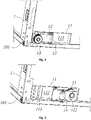
- the bracket 12 has an anti-skid position and a rolling position within a range of travel of the bracket 12 about the pivot 15. Referring to FIG. 2 , in the anti-skid position, the foot 13 touches the floor and the roller 14 is off the floor; Referring to FIG. 3 , in the rolling position, the roller 14 touches the floor and the foot 13 is off the floor.
- the roller 14 touches the floor and thereby rolls relative to the floor, which facilitates the movement of the refrigerator 100.
- the bracket 12 is rotated from the rolling position to the anti-skid position.
- the roller 14 is off the floor, and the foot 13 touches the floor to support the refrigerator 100, thereby fixing the position of the refrigerator 100 and solving the problem of easy displacement of the refrigerator 100 due to an excessive door-opening force;
- the foot 13 and the roller 14 are respectively connected to the bracket 12, and the structure between the foot 13 and the bracket 12 and between the roller 14 and the bracket 12 is firm.
- bracket 12 when the bracket 12 changes between the anti-skid position and the rolling position, it rotates about the pivot 15 by 180° relative to the fixed base 11.
- the fixed base 11 is generally configured as a rectangular box-shaped structure that opens downward, and configured to have a first accommodating cavity 112 and a second accommodating cavity 111 that are recessed upward.
- the first accommodating cavity 112 is located in front of the through hole 114
- the second accommodating cavity 111 is located in rear of the through hole 114.
- FIG. 2 when the bracket 12 is located in the anti-skid position, the roller 14 is accommodated in the first accommodating cavity 112, and the foot 13 is located below the bracket 12 and the fixed base 11; and referring to FIG. 3 , when the bracket 12 is located in the rolling position, the foot 13 is accommodated in the second accommodating cavity 111, and the roller 14 is located below the bracket 12 and the fixed base 11.
- first accommodating cavity 112 for accommodating the roller 14 and the second accommodating cavity 111 for accommodating the foot 13 hidden states of the roller 14 and the foot 13 when they are respectively off the floor can be achieved, thereby avoiding accidental collision and damages of the exposed roller and foot when they needn't touch the floor, and improving the aesthetics of the bottom of the refrigerator 100.
- roller 14 and the foot 13 are separately disposed on opposite sides of the bracket 12. Such a spatial arrangement enables the roller 14, the foot 13 and the bracket 12 to be arranged more concise and reasonable in space while enabling the roller 14 and foot 13 to touch the floor alternatingly.
- the bracket 12 comprises a support plate, the support plate has a first surface 121 and a second surface 122 parallel to and opposite to the first surface 121 in a first direction, and the roller 14 is disposed on a side where the second surface 122 of the support plate lies, and the foot 13 is disposed on the side where the first surface 121 of the support plate lies.
- the roller 14 is located on the side of the second surface 122 away from the first surface 121, and the foot 13 is located on the side of the first surface 121 away from the second surface 122.
- the roller 14, the second surface 122, the first surface 121 and the foot 13 are arranged sequentially.
- Such spatial arrangement makes the spatial arrangement of the rollers 14, the foot 13 and the bracket 12 more concise and reasonable.
- the support plate extends substantially along a plane, and the first direction is a vertical direction of the support plate.
- the first surface 121 and the second surface 122 constitute two major surfaces of the support plate which are large in area, parallel to and opposite to each other. The two surfaces are perpendicular to the vertical direction.
- the support plate In the anti-skid position and the rolling position, the support plate extends substantially in the horizontal direction, the first direction is an up-down direction, the second surface 122 is vertically opposite to the first surface 121, and correspondingly, the roller 14 and the feet 13 are separately disposed on upper and lower sides of the support plate.
- the second surface 122 In the anti-skid position, the second surface 122 is above the first surface 121, the roller 14 is located on the upper side of the support plate, and the foot 13 is located on the lower side of the support plate; in the rolling position, the second surface 122 is below the first surface 121, the roller 14 is located on the lower side of the support plate, and the foot 13 is located on the lower side of the support plate.
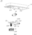
- the bracket 12 further comprises two cantilevered plates 123 connected with left and right edges of the support plate; the two cantilevered plates 123 are arranged opposite to each other in the left-right direction and protrude from the second surface 122 in the aforesaid first direction; each cantilevered plate 123 has a through hole 1230.
- the left and right ends of the roller 14 are rotatably arranged in the through holes 1230 so that the roller 14 is relatively rotatably connected to the bracket 12 about an axis extending in the left-right direction, such that the refrigerator 100 can roll back and forth along the floor via the roller 14 when the bracket is in the rolling position.
- the foot 13 is assembled and fitted to the bracket 12 through a threaded structure.
- the threaded structure comprises a bolt 124 and a threaded hole adapted thereto.
- the bolt 124 is fixedly connected to the support plate and protrudes from the first surface 121 in the first direction, and the threaded hole is provided in the center of the foot 13.
- the foot 13 is fitted to the bracket 12 in a way of being screwed in or out in the first direction.
- the first direction is the up-down direction
- the foot 13 is screwed in or out in the up-down direction relative to the bracket 12 through the engagement of the threaded hole and the bolt 124.
- a horizontal plane where the pivot 15 is located is defined by a horizontal plane where a center line of the pivot 15 is located.
- a bottom end of the roller 14 touches the floor, there is a first height difference in the up-down direction between the bottom end of the roller 14 and the horizontal plane where the pivot 15 lies, and the first height difference is a height by the horizontal plane where the pivot 15 lies is above the floor;
- a bottom end 130 of the foot 13 touches the floor, there is a second height difference in the up-down direction between the bottom end 130 of the foot 13 and the horizontal plane where the pivot 15 lies, and the second height difference is a height by the horizontal plane where the pivot 15 lies is above the floor.
- the second height difference changes between greater than the first height difference and less than the first height difference.
- the height may be adjusted through the threaded structure.
- the height by which the foot 13 lifts up the cabinet 1 can be larger than or smaller than the height by which the roller 14 lifts up the cabinet 1, thereby adjusting the cabinet 1 in balance.
- the foot 11 when the bracket 12 is in the anti-skid position, the foot 11 is located on the lower side of the support plate as described above, the fixed base 11 resists a partial region of the second surface 122 from above, and the partial region is located vertically above (i.e., just above) the foot 13. As such, the downward pressure of the cabinet 1 is transmitted vertically downward via the bracket 12, through the support plate to the foot 13, thereby avoiding a torque force received by the pivot 15 or bracket 12 itself.
- the roller 14 When the bracket 12 is in the rolling position, the roller 14 is located on the lower side of the support plate as stated above, the foot 13 is located on the upper side of the support plate, the fixed base 11 resists the foot 13 from above, i.e., the foot 13 resists a top wall of the second accommodating cavity 111. In this way, in addition to the position of the pivot 15, the downward pressure of the cabinet 1 may also be transmitted downward to the roller 14 through the foot 13 and the bracket 12, to maintain structural stability.
- the pivot 15, the roller 14 and the foot 13 are arranged sequentially.
- the roller 14 is located between the pivot 15 and the foot 13, and the bracket 12 resists the fixed base 11 through the pivot 15 and the foot 13, thereby ensuring the structural strength and position stability at the roller 14.
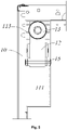
- the fixed base 11 has a plurality of ribs 113 located in front of the first accommodating cavity 112.
- the ribs 113 resist the abovementioned partial region of the second surface 122 from above, that is, the ribs 113 are located vertically above (i.e., just above) the foot 13, thereby facilitating resisting and limiting the bracket 12 and transmitting the pressure to the bracket 12.
- the bottom end 130 of the foot 13 is provided with a rubber end face. Therefore, when the bracket 12 is in the anti-skid position, the bottom end 130 touches the floor to further avoid the accidental displacement of the refrigerator 100 due to an excessive door-opening force through the flexibility and high friction coefficient of the bottom end 130, thereby ensuring positional stability.
- the cabinet 1 has a connection side 102 pivotally connected to the door body and an opening and closing side 101 disposed opposite to the connection side 102 in the left-right direction.
- the base support assembly 10 is disposed below the opening and closing side 101, and a second roller 20 is disposed below the connection side 102, that is, the base support assembly 10 is disposed relatively close to the opening and closing side 101 among both the connection side 102 and the opening and closing side 101, while the second roller 20 is disposed relatively close to the connection side 102 among both the connection side 102 and the opening and closing side 101.
- the present embodiment may prevent the opening and closing side 101 from move accidentally through the base support assembly 10, may achieve fast movement of the refrigerator 100 through the cooperation of the second roller 20 and the roller 14, thereby avoiding excessively cumbersome operations upon moving the refrigerator 100 caused by an excessive number of base support assemblies 10 arranged.
- the present invention has the following advantageous effects: on the one hand, by switching the bracket 12 between the rolling position and the anti-skid position, the problem of easy displacement caused by the opening of the door after the refrigerator 100 is placed at a proper position can be solved, and the refrigerator 100 is facilitated to move if necessary; on the other hand, the foot 13 and roller 14 are both connected to the bracket 12, and the structures of the parts in the base support assembly 10 are optimized, so that the construction is firm.
Landscapes
- Engineering & Computer Science (AREA)
- General Engineering & Computer Science (AREA)
- Mechanical Engineering (AREA)
- Chemical & Material Sciences (AREA)
- Combustion & Propulsion (AREA)
- Physics & Mathematics (AREA)
- Thermal Sciences (AREA)
- Refrigerator Housings (AREA)
Abstract
Description
- The present invention relates to a base support assembly and a refrigerator having the same, and belongs to the technical field of household appliance.
- A refrigerator usually employs rollers or feet as base supporting members, which mainly function to support the refrigerator.
- If the roller-type base supporting members are employed, since the rollers are rollable relative to the floor, the refrigerators are usually displaced when a large force is applied to open or close the door. Particularly, as people's living standards improve, there is an increasing demand for the capacity of the refrigerator. Large-volume refrigerators increasingly become best-sellers in the market. However, a larger force needs to be applied to the large-volume refrigerators than conventional refrigerators, and the problem of the displacement of refrigerators is more serious.
- If the foot-type base supporting members are employed, since sliding friction exists between the feet and the floor, the refrigerator can be firmly retained at a placement position, but there occurs a problem that the refrigerator is inconvenient to move. Moving the refrigerator forcedly will abrade the floor or damage the feet.
- In view of the above drawbacks in the prior art, an object of the present invention is to provide a base support assembly and a refrigerator having the same, which can solve a problem in the prior art that position fixation and movement of the refrigerator cannot be considered simultaneously.
- To achieve the above object of the present invention, an embodiment provides a base support assembly, the base support assembly comprises a fixed base, a bracket, a foot disposed on the bracket, and a roller rotatably coupled to the bracket;
- the bracket is rotatably fitted about a horizontal pivot below the fixed base, to have, relative to the fixed base, an anti-skid position in which the foot touches the floor and the roller is off the floor and a rolling position in which the foot is off the floor and the roller touches the floor.
- Optionally, when the bracket changes between the anti-skid position and the rolling position, the bracket rotates about the pivot by 180° relative to the fixed base.
- Optionally, the fixed base has a first accommodating cavity and a second accommodating cavity that are recessed upward;
- when the bracket is located in the anti-skid position, the roller is accommodated in the first accommodating cavity;
- when the bracket is located in the rolling position, the foot is accommodated in the second accommodating cavity.
- Optionally, the foot is assembled and fitted to a pad of the bracket through a threaded structure.
- Optionally, when the bracket is in the rolling position, there is a first height difference in an up-down direction between a bottom end of the roller and a horizontal plane where the pivot lies;
- when the bracket is in the anti-skid position, there is a second height difference in the up-down direction between the bottom end of the foot and the horizontal plane where the pivot lies, and as a screw-in depth of the threaded structure changes, the second height difference changes between greater than the first height difference and less than the first height difference.
- Optionally, the roller and the foot are separately disposed on opposite sides of the bracket;
- the bracket comprises a support plate, the support plate has a first surface and a second surface opposite to the first surface in a first direction, the roller is disposed on a side where the second surface of the support plate lies, and the foot is disposed on a side where the first surface of the support plate lies.
- Optionally, when the bracket is in the anti-skid position, the first direction is an up-down direction, the foot is located below the support plate, and the fixed base resists, from above, a partial region which is of the second surface and vertically above the foot.
- Optionally, when the bracket is in the rolling position, the first direction is the up-down direction, and the foot is located above the support plate; the pivot, the roller and the foot are disposed in sequentially in a horizontal direction perpendicular to the pivot, and the fixed base resists the foot from above.
- To achieve the above object of the present invention, an embodiment of the present invention provides a refrigerator, comprising a cabinet and a base support assembly, and the base support assembly is disposed on an underside of the cabinet and comprises a fixed base, a bracket, a foot disposed on the bracket, and a roller rotatably coupled to the bracket; the base support assembly is connected to the cabinet through the fixed base.
- the bracket is rotatably fitted about a horizontal pivot below the fixed base, to have, relative to the fixed base, an anti-skid position in which the foot touches the floor and the roller is off the floor and a rolling position in which the foot is off the floor and the roller touches the floor.
- Optionally, when the bracket changes between the anti-skid position and the rolling position, the bracket rotates about the pivot by 180° relative to the fixed base.
- Optionally, the fixed base has a first accommodating cavity and a second accommodating cavity that are recessed upward;
- when the bracket is located in the anti-skid position, the roller is accommodated in the first accommodating cavity;
- when the bracket is located in the rolling position, the foot is accommodated in the second accommodating cavity.
- Optionally, the foot is assembled and fitted to a pad of the bracket through a threaded structure.
- Optionally, when the bracket is in the rolling position, there is a first height difference in an up-down direction between a bottom end of the roller and a horizontal plane where the pivot lies;
- when the bracket is in the anti-skid position, there is a second height difference in the up-down direction between the bottom end of the foot and the horizontal plane where the pivot lies, and as a screw-in depth of the threaded structure changes, the second height difference changes between greater than the first height difference and less than the first height difference.
- Optionally, the roller and the foot are separately disposed on opposite sides of the bracket;
- the bracket comprises a support plate, the support plate has a first surface and a second surface opposite to the first surface in a first direction, the roller is disposed on a side where the second surface of the support plate lies, and the foot is disposed on a side where the first surface of the support plate lies.
- Optionally, when the bracket is in the anti-skid position, the first direction is an up-down direction, the foot is located below the support plate, and the fixed base resists, from above, a partial region which is of the second surface and vertically above the foot.
- Optionally, when the bracket is in the rolling position, the first direction is the up-down direction, and the foot is located above the support plate; the pivot, the roller and the foot are disposed in sequentially in a horizontal direction perpendicular to the pivot, and the fixed base resists the foot from above.
- Optionally, the refrigerator further comprises a door body movably disposed on a front side of the cabinet, the cabinet having a connection side pivotally connected to the door body and an opening and closing side disposed opposite to the connection side in a left-right direction, wherein the base support assembly is disposed below the opening and closing side, and the refrigerator further comprises a second roller disposed below the connection side.
- As compared with the prior art, the present invention has the following advantageous effects: with the foot and the roller being provided on the bracket and with the bracket being arranged to be rotatable relative to the fixed base, the foot and the roller can be made selectively touch the floor; if the refrigerator needs to be moved, the bracket is rotated to the rolling position, and the roller rolls along the floor to thereby achieve the movement of the refrigerator; after the refrigerator is placed in position, the bracket is rotated to the anti-skid position, and the foot touches the floor in place of the roller, thereby achieving the position fixation of the refrigerator, solving the problem of easy displacement due to a large door-opening force and solving the problem in the prior art that position fixation and movement of the refrigerator cannot be considered simultaneously; furthermore, the structural stability is enhanced by disposing the roller and the foot on the bracket.
-
-
FIG. 1 is a front view of a cabinet structure portion of a refrigerator according to an embodiment of the present invention; -
FIG. 2 is a schematic structural view of a base support assembly on an underside of a cabinet according to an embodiment of the present invention, wherein a bracket is in its anti-skid position; -
FIG. 3 is a schematic structural view of a base support assembly on an underside of a cabinet according to an embodiment of the present invention, wherein the bracket is in its rolling position; -
FIG. 4 is an exploded structural view of a base support assembly according to an embodiment of the present invention; -
FIG. 5 is a bottom view of the base support assembly on an underside of a cabinet according to an embodiment of the present invention. - Implementations of the present invention will be described in detail in conjunction with specific embodiments shown in the figures. However, these embodiments are not intended to limit the present invention. Structural, methodological or functional variations made by those having ordinary skill in the art according to these implementations are all comprised in the protection scope of the present invention.
- Referring to
FIG. 1 through FIG. 5 , an embodiment of the present invention provides abase support assembly 10, and provides arefrigerator 100 comprising thebase support assembly 10, particularly a large-volume refrigerator, that is, provides an application of thebase support assembly 10 on therefrigerator 100. Certainly, thebase support assembly 10 may also be applied to other cabinet-type appliances such as freezers and washing machines. - Referring to
FIG. 1 , therefrigerator 100 comprises acabinet 1, a door body and thebase support assembly 10. The door body is movably disposed on a front side of thecabinet 1 to open or close an internal storage space of thecabinet 1; thebase support assembly 10 is disposed on an underside of thecabinet 1 to support therefrigerator 100 on the floor, so that thecabinet 1 is spaced upward apart from the floor by a certain distance. In the present application, the floor generally refers to a supporting surface for placing therefrigerator 100. - Referring to
FIG. 2 to FIG. 5 , thebase support assembly 10 comprises afixed base 11, abracket 12, afoot 13 disposed on thebracket 12, and aroller 14 rotatably coupled to thebracket 12. - The
fixed base 11 is used to fix the entirebase support assembly 10 on the underside of thecabinet 1. In the present embodiment, thefixed base 11 and a bottom plate of thecabinet 1 are arranged separately. Furthermore, before the foam molding of a thermal insulation layer of thecabinet 1, thefixed base 11 and the bottom plate of thecabinet 1 are first assembled and connected via a screw, a sponge strip, an adhesive tape or other fastening manner, so that after the subsequent foam molding of the thermal insulation layer, the tight connection between thefixed base 11 and the bottom plate may be achieved. Certainly, in a variant embodiment, thefixed base 11 may be integrally formed with the bottom plate of thecabinet 1, i.e., thefixed base 11 is integrally formed on the bottom plate. - The
bracket 12 is rotatably fitted about ahorizontal pivot 15 below thefixed base 11. Specifically, in the present embodiment, thepivot 15 extends horizontally in a left-right direction, thefixed base 11 has a pair of pivot arms protruding downward, and each of the pivot arms has a throughhole 114; thepivot 15 is configured nearby an end of thebracket 12 in a front-rear direction, and left and right ends of thepivot 15 are rotatably mated in the throughholes 114, so that thebracket 12 may be connected to thefixed base 11 rotatably about thepivot 15. - The
bracket 12 has an anti-skid position and a rolling position within a range of travel of thebracket 12 about thepivot 15. Referring toFIG. 2 , in the anti-skid position, thefoot 13 touches the floor and theroller 14 is off the floor; Referring toFIG. 3 , in the rolling position, theroller 14 touches the floor and thefoot 13 is off the floor. - Therefore, on the one hand, when the
base support assembly 10 is applied to therefrigerator 100, in the rolling position theroller 14 touches the floor and thereby rolls relative to the floor, which facilitates the movement of therefrigerator 100. After therefrigerator 100 is placed at a proper position, thebracket 12 is rotated from the rolling position to the anti-skid position. At this time, theroller 14 is off the floor, and thefoot 13 touches the floor to support therefrigerator 100, thereby fixing the position of therefrigerator 100 and solving the problem of easy displacement of therefrigerator 100 due to an excessive door-opening force; on the other hand, thefoot 13 and theroller 14 are respectively connected to thebracket 12, and the structure between thefoot 13 and thebracket 12 and between theroller 14 and thebracket 12 is firm. - Furthermore, when the
bracket 12 changes between the anti-skid position and the rolling position, it rotates about thepivot 15 by 180° relative to the fixedbase 11. - In the present embodiment, the fixed
base 11 is generally configured as a rectangular box-shaped structure that opens downward, and configured to have a firstaccommodating cavity 112 and a secondaccommodating cavity 111 that are recessed upward. The firstaccommodating cavity 112 is located in front of the throughhole 114, and the secondaccommodating cavity 111 is located in rear of the throughhole 114. Referring toFIG. 2 , when thebracket 12 is located in the anti-skid position, theroller 14 is accommodated in the firstaccommodating cavity 112, and thefoot 13 is located below thebracket 12 and the fixedbase 11; and referring toFIG. 3 , when thebracket 12 is located in the rolling position, thefoot 13 is accommodated in the secondaccommodating cavity 111, and theroller 14 is located below thebracket 12 and the fixedbase 11. Therefore, by providing the firstaccommodating cavity 112 for accommodating theroller 14 and the secondaccommodating cavity 111 for accommodating thefoot 13, hidden states of theroller 14 and thefoot 13 when they are respectively off the floor can be achieved, thereby avoiding accidental collision and damages of the exposed roller and foot when they needn't touch the floor, and improving the aesthetics of the bottom of therefrigerator 100. - Furthermore, the
roller 14 and thefoot 13 are separately disposed on opposite sides of thebracket 12. Such a spatial arrangement enables theroller 14, thefoot 13 and thebracket 12 to be arranged more concise and reasonable in space while enabling theroller 14 andfoot 13 to touch the floor alternatingly. - Specifically, the
bracket 12 comprises a support plate, the support plate has afirst surface 121 and asecond surface 122 parallel to and opposite to thefirst surface 121 in a first direction, and theroller 14 is disposed on a side where thesecond surface 122 of the support plate lies, and thefoot 13 is disposed on the side where thefirst surface 121 of the support plate lies. In other words, theroller 14 is located on the side of thesecond surface 122 away from thefirst surface 121, and thefoot 13 is located on the side of thefirst surface 121 away from thesecond surface 122. In the first direction, theroller 14, thesecond surface 122, thefirst surface 121 and thefoot 13 are arranged sequentially. Such spatial arrangement makes the spatial arrangement of therollers 14, thefoot 13 and thebracket 12 more concise and reasonable. - In the present embodiment, the support plate extends substantially along a plane, and the first direction is a vertical direction of the support plate. Correspondingly, the
first surface 121 and thesecond surface 122 constitute two major surfaces of the support plate which are large in area, parallel to and opposite to each other. The two surfaces are perpendicular to the vertical direction. - In the anti-skid position and the rolling position, the support plate extends substantially in the horizontal direction, the first direction is an up-down direction, the
second surface 122 is vertically opposite to thefirst surface 121, and correspondingly, theroller 14 and thefeet 13 are separately disposed on upper and lower sides of the support plate. In the anti-skid position, thesecond surface 122 is above thefirst surface 121, theroller 14 is located on the upper side of the support plate, and thefoot 13 is located on the lower side of the support plate; in the rolling position, thesecond surface 122 is below thefirst surface 121, theroller 14 is located on the lower side of the support plate, and thefoot 13 is located on the lower side of the support plate. - Furthermore, the
bracket 12 further comprises two cantileveredplates 123 connected with left and right edges of the support plate; the two cantileveredplates 123 are arranged opposite to each other in the left-right direction and protrude from thesecond surface 122 in the aforesaid first direction; eachcantilevered plate 123 has a throughhole 1230. The left and right ends of theroller 14 are rotatably arranged in the throughholes 1230 so that theroller 14 is relatively rotatably connected to thebracket 12 about an axis extending in the left-right direction, such that therefrigerator 100 can roll back and forth along the floor via theroller 14 when the bracket is in the rolling position. - Furthermore, the
foot 13 is assembled and fitted to thebracket 12 through a threaded structure. Specifically in the present embodiment, the threaded structure comprises abolt 124 and a threaded hole adapted thereto. Thebolt 124 is fixedly connected to the support plate and protrudes from thefirst surface 121 in the first direction, and the threaded hole is provided in the center of thefoot 13. Through the engagement of the threaded hole and thebolt 124, thefoot 13 is fitted to thebracket 12 in a way of being screwed in or out in the first direction. - As stated above, in the anti-skid position and in the rolling position, the first direction is the up-down direction, and the
foot 13 is screwed in or out in the up-down direction relative to thebracket 12 through the engagement of the threaded hole and thebolt 124. - A horizontal plane where the
pivot 15 is located is defined by a horizontal plane where a center line of thepivot 15 is located. Preferably, when thebracket 12 is in the rolling position, a bottom end of theroller 14 touches the floor, there is a first height difference in the up-down direction between the bottom end of theroller 14 and the horizontal plane where thepivot 15 lies, and the first height difference is a height by the horizontal plane where thepivot 15 lies is above the floor; when thebracket 12 is in the anti-skid position, abottom end 130 of thefoot 13 touches the floor, there is a second height difference in the up-down direction between thebottom end 130 of thefoot 13 and the horizontal plane where thepivot 15 lies, and the second height difference is a height by the horizontal plane where thepivot 15 lies is above the floor. In the present application, as a screw-in depth of the threaded structure changes, the second height difference changes between greater than the first height difference and less than the first height difference. In this way, the height may be adjusted through the threaded structure. On this basis, as the screw-in depth of the threaded structure is adjusted, the height by which thefoot 13 lifts up thecabinet 1 can be larger than or smaller than the height by which theroller 14 lifts up thecabinet 1, thereby adjusting thecabinet 1 in balance. - Furthermore, when the
bracket 12 is in the anti-skid position, thefoot 11 is located on the lower side of the support plate as described above, the fixedbase 11 resists a partial region of thesecond surface 122 from above, and the partial region is located vertically above (i.e., just above) thefoot 13. As such, the downward pressure of thecabinet 1 is transmitted vertically downward via thebracket 12, through the support plate to thefoot 13, thereby avoiding a torque force received by thepivot 15 orbracket 12 itself. - When the
bracket 12 is in the rolling position, theroller 14 is located on the lower side of the support plate as stated above, thefoot 13 is located on the upper side of the support plate, the fixedbase 11 resists thefoot 13 from above, i.e., thefoot 13 resists a top wall of the secondaccommodating cavity 111. In this way, in addition to the position of thepivot 15, the downward pressure of thecabinet 1 may also be transmitted downward to theroller 14 through thefoot 13 and thebracket 12, to maintain structural stability. - Preferably, in the horizontal direction perpendicular to the
pivot 15, i.e., in the front-rear direction in the present embodiment, thepivot 15, theroller 14 and thefoot 13 are arranged sequentially. In this way, when thebracket 12 is in the rolling position, theroller 14 is located between thepivot 15 and thefoot 13, and thebracket 12 resists the fixedbase 11 through thepivot 15 and thefoot 13, thereby ensuring the structural strength and position stability at theroller 14. - Furthermore, the fixed
base 11 has a plurality ofribs 113 located in front of the firstaccommodating cavity 112. When thebracket 12 is in the anti-skid position, theribs 113 resist the abovementioned partial region of thesecond surface 122 from above, that is, theribs 113 are located vertically above (i.e., just above) thefoot 13, thereby facilitating resisting and limiting thebracket 12 and transmitting the pressure to thebracket 12. - Furthermore, the
bottom end 130 of thefoot 13 is provided with a rubber end face. Therefore, when thebracket 12 is in the anti-skid position, thebottom end 130 touches the floor to further avoid the accidental displacement of therefrigerator 100 due to an excessive door-opening force through the flexibility and high friction coefficient of thebottom end 130, thereby ensuring positional stability. - Furthermore, further referring to
FIG. 1 , thecabinet 1 has aconnection side 102 pivotally connected to the door body and an opening and closingside 101 disposed opposite to theconnection side 102 in the left-right direction. Thebase support assembly 10 is disposed below the opening and closingside 101, and asecond roller 20 is disposed below theconnection side 102, that is, thebase support assembly 10 is disposed relatively close to the opening and closingside 101 among both theconnection side 102 and the opening and closingside 101, while thesecond roller 20 is disposed relatively close to theconnection side 102 among both theconnection side 102 and the opening and closingside 101. Therefore, since the opening and closingside 101 is more likely to move accidentally than theconnection side 102 as the door is opened and closed, the present embodiment may prevent the opening and closingside 101 from move accidentally through thebase support assembly 10, may achieve fast movement of therefrigerator 100 through the cooperation of thesecond roller 20 and theroller 14, thereby avoiding excessively cumbersome operations upon moving therefrigerator 100 caused by an excessive number ofbase support assemblies 10 arranged. - To conclude, as compared with the prior art, the present invention has the following advantageous effects: on the one hand, by switching the
bracket 12 between the rolling position and the anti-skid position, the problem of easy displacement caused by the opening of the door after therefrigerator 100 is placed at a proper position can be solved, and therefrigerator 100 is facilitated to move if necessary; on the other hand, thefoot 13 androller 14 are both connected to thebracket 12, and the structures of the parts in thebase support assembly 10 are optimized, so that the construction is firm. - The detailed descriptions set forth above are merely specific illustrations of feasible embodiments of the present invention, and are not intended to limit the scope of protection of the present invention. All equivalent embodiments or modifications that do not depart from the art spirit of the present invention should fall within the scope of protection of the present invention.
Claims (10)
- A base support assembly, wherein the base support assembly comprises a fixed base, a bracket, a foot disposed on the bracket, and a roller rotatably coupled to the bracket;
the bracket is rotatably fitted about a horizontal pivot below the fixed base, to have, relative to the fixed base, an anti-skid position in which the foot touches the floor and the roller is off the floor and a rolling position in which the foot is off the floor and the roller touches the floor. - The base support assembly according to claim 1, wherein when the bracket changes between the anti-skid position and the rolling position, the bracket rotates about the pivot by 180° relative to the fixed base.
- The base support assembly according to claim 1, wherein the fixed base has a first accommodating cavity and a second accommodating cavity that are recessed upward;when the bracket is located in the anti-skid position, the roller is accommodated in the first accommodating cavity;when the bracket is located in the rolling position, the foot is accommodated in the second accommodating cavity.
- The base support assembly according to claim 1, wherein the foot is assembled and fitted to a pad of the bracket through a threaded structure.
- The base support assembly according to claim 4, wherein when the bracket is in the rolling position, there is a first height difference in an up-down direction between a bottom end of the roller and a horizontal plane where the pivot lies;
when the bracket is in the anti-skid position, there is a second height difference in the up-down direction between the bottom end of the foot and the horizontal plane where the pivot lies, and as a screw-in depth of the threaded structure changes, the second height difference changes between greater than the first height difference and less than the first height difference. - The base support assembly according to claim 1, wherein the roller and the foot are separately disposed on opposite sides of the bracket;
the bracket comprises a support plate, the support plate has a first surface and a second surface opposite to the first surface in a first direction, the roller is disposed on a side where the second surface of the support plate lies, and the foot is disposed on a side where the first surface of the support plate lies. - The base support assembly according to claim 6, wherein when the bracket is in the anti-skid position, the first direction is an up-down direction, the foot is located below the support plate, and the fixed base resists, from above, a partial region which is of the second surface and vertically above the foot.
- The base support assembly according to claim 7, wherein when the bracket is in the rolling position, the first direction is the up-down direction, and the foot is located above the support plate; the pivot, the roller and the foot are disposed in sequentially in a horizontal direction perpendicular to the pivot, and the fixed base resists the foot from above.
- A refrigerator, comprising a cabinet, wherein the refrigerator comprises the base support assembly according to claim 1, and the base support assembly is disposed on an underside of the cabinet and connected to the cabinet through the fixed base.
- The refrigerator according to claim 9, further comprising a door body movably disposed on a front side of the cabinet, the cabinet having a connection side pivotally connected to the door body and an opening and closing side disposed opposite to the connection side in a left-right direction, wherein the base support assembly is disposed below the opening and closing side, and the refrigerator further comprises a second roller disposed below the connection side.
Applications Claiming Priority (2)
| Application Number | Priority Date | Filing Date | Title |
|---|---|---|---|
| CN202010170303.3A CN113390224B (en) | 2020-03-12 | 2020-03-12 | Bottom support assembly and refrigerator with same |
| PCT/CN2021/072639 WO2021179797A1 (en) | 2020-03-12 | 2021-01-19 | Bottom support assembly and refrigerator having same |
Publications (2)
| Publication Number | Publication Date |
|---|---|
| EP4119870A1 true EP4119870A1 (en) | 2023-01-18 |
| EP4119870A4 EP4119870A4 (en) | 2023-07-26 |
Family
ID=77615610
Family Applications (1)
| Application Number | Title | Priority Date | Filing Date |
|---|---|---|---|
| EP21768237.6A Withdrawn EP4119870A4 (en) | 2020-03-12 | 2021-01-19 | BOTTOM RACK ASSEMBLY AND REFRIGERATOR INCLUDING IT |
Country Status (4)
| Country | Link |
|---|---|
| EP (1) | EP4119870A4 (en) |
| JP (1) | JP7463542B2 (en) |
| CN (1) | CN113390224B (en) |
| WO (1) | WO2021179797A1 (en) |
Families Citing this family (2)
| Publication number | Priority date | Publication date | Assignee | Title |
|---|---|---|---|---|
| CN113390224B (en) * | 2020-03-12 | 2025-09-09 | 青岛海尔特种电冰柜有限公司 | Bottom support assembly and refrigerator with same |
| CN117308465A (en) * | 2022-06-23 | 2023-12-29 | 青岛海尔电冰箱有限公司 | Anti-tipping bracket for refrigerator and refrigerator |
Family Cites Families (12)
| Publication number | Priority date | Publication date | Assignee | Title |
|---|---|---|---|---|
| JPS5846085U (en) * | 1981-09-21 | 1983-03-28 | 松下冷機株式会社 | refrigerator |
| JPS6158483U (en) * | 1984-09-20 | 1986-04-19 | ||
| JPH01181082A (en) * | 1988-01-13 | 1989-07-19 | Matsushita Refrig Co Ltd | Refrigerator |
| JPH02279973A (en) * | 1989-04-19 | 1990-11-15 | Matsushita Refrig Co Ltd | Adjustable handle for refrigerator |
| US4955569A (en) * | 1989-07-18 | 1990-09-11 | Sub-Zero Freezer Company, Inc. | Refrigerator leveling system |
| CN104677030A (en) * | 2015-03-13 | 2015-06-03 | 湖北美的电冰箱有限公司 | Foot assembly for refrigerator and refrigerator with foot assembly |
| CN105042997B (en) * | 2015-05-26 | 2017-12-05 | 遵义市凤华电器有限责任公司 | refrigerator footing device |
| CN205447124U (en) * | 2016-03-30 | 2016-08-10 | 台达电子工业股份有限公司 | Movable foot pad device |
| CN206256277U (en) * | 2016-10-31 | 2017-06-16 | 无锡飞翎电子有限公司 | Washing machine |
| CN109058671A (en) * | 2018-09-18 | 2018-12-21 | 赵自文 | A kind of new-type hand-rail type 3D printer firm banking |
| CN212109175U (en) * | 2020-03-12 | 2020-12-08 | 青岛海尔特种电冰柜有限公司 | Bottom support assembly and refrigerator with same |
| CN113390224B (en) * | 2020-03-12 | 2025-09-09 | 青岛海尔特种电冰柜有限公司 | Bottom support assembly and refrigerator with same |
-
2020
- 2020-03-12 CN CN202010170303.3A patent/CN113390224B/en active Active
-
2021
- 2021-01-19 WO PCT/CN2021/072639 patent/WO2021179797A1/en not_active Ceased
- 2021-01-19 EP EP21768237.6A patent/EP4119870A4/en not_active Withdrawn
- 2021-01-19 JP JP2022554915A patent/JP7463542B2/en active Active
Also Published As
| Publication number | Publication date |
|---|---|
| WO2021179797A1 (en) | 2021-09-16 |
| EP4119870A4 (en) | 2023-07-26 |
| CN113390224A (en) | 2021-09-14 |
| CN113390224B (en) | 2025-09-09 |
| JP2023518010A (en) | 2023-04-27 |
| JP7463542B2 (en) | 2024-04-08 |
Similar Documents
| Publication | Publication Date | Title |
|---|---|---|
| EP4119870A1 (en) | Bottom support assembly and refrigerator having same | |
| US8801124B2 (en) | Refrigerator having storage container | |
| US8851589B2 (en) | Refrigerator includes an auxiliary shelf folded by contacting a shelf guide on a back surface of a second door | |
| KR101030879B1 (en) | Furniture with automatic door closing | |
| CN223106392U (en) | Door assemblies and refrigeration equipment | |
| CN108106311B (en) | Refrigerator with a door | |
| KR101137412B1 (en) | Desk for computer used for public place | |
| US20220408910A1 (en) | Dual-purpose folding table | |
| CN215255202U (en) | Door assemblies and lockers | |
| CN212109175U (en) | Bottom support assembly and refrigerator with same | |
| CN117927105A (en) | Buffering adjustable hinge | |
| CN202926063U (en) | Refrigerator and door body hinge thereof | |
| CN212179333U (en) | refrigerator | |
| CN215255732U (en) | Door assemblies and lockers | |
| CN221761683U (en) | Buffering adjustable hinge | |
| CN202074774U (en) | Rotary shelf and refrigerator | |
| JP2004286402A (en) | refrigerator | |
| CN222032286U (en) | Drawer cabinet and dishwasher | |
| CN223855983U (en) | Shelf storage device and refrigeration equipment | |
| KR101403165B1 (en) | Camping Trailer | |
| CN217309762U (en) | Mirror cabinet | |
| CN216534432U (en) | Archives save set is used in office management | |
| JPH0624542Y2 (en) | Sliding device for storage door | |
| CN211233517U (en) | A kind of refrigerator | |
| KR101334013B1 (en) | Folding type camping trailer |
Legal Events
| Date | Code | Title | Description |
|---|---|---|---|
| STAA | Information on the status of an ep patent application or granted ep patent |
Free format text: STATUS: THE INTERNATIONAL PUBLICATION HAS BEEN MADE |
|
| PUAI | Public reference made under article 153(3) epc to a published international application that has entered the european phase |
Free format text: ORIGINAL CODE: 0009012 |
|
| STAA | Information on the status of an ep patent application or granted ep patent |
Free format text: STATUS: REQUEST FOR EXAMINATION WAS MADE |
|
| 17P | Request for examination filed |
Effective date: 20220329 |
|
| AK | Designated contracting states |
Kind code of ref document: A1 Designated state(s): AL AT BE BG CH CY CZ DE DK EE ES FI FR GB GR HR HU IE IS IT LI LT LU LV MC MK MT NL NO PL PT RO RS SE SI SK SM TR |
|
| DAV | Request for validation of the european patent (deleted) | ||
| DAX | Request for extension of the european patent (deleted) | ||
| A4 | Supplementary search report drawn up and despatched |
Effective date: 20230628 |
|
| RIC1 | Information provided on ipc code assigned before grant |
Ipc: A47B 91/02 20060101ALI20230622BHEP Ipc: F16M 7/00 20060101ALI20230622BHEP Ipc: F25D 11/00 20060101ALI20230622BHEP Ipc: F25D 23/00 20060101AFI20230622BHEP |
|
| GRAP | Despatch of communication of intention to grant a patent |
Free format text: ORIGINAL CODE: EPIDOSNIGR1 |
|
| STAA | Information on the status of an ep patent application or granted ep patent |
Free format text: STATUS: GRANT OF PATENT IS INTENDED |
|
| INTG | Intention to grant announced |
Effective date: 20250512 |
|
| STAA | Information on the status of an ep patent application or granted ep patent |
Free format text: STATUS: THE APPLICATION IS DEEMED TO BE WITHDRAWN |
|
| 18D | Application deemed to be withdrawn |
Effective date: 20250913 |