EP4119869A1 - Refrigerator appliance - Google Patents
Refrigerator appliance Download PDFInfo
- Publication number
- EP4119869A1 EP4119869A1 EP22171700.2A EP22171700A EP4119869A1 EP 4119869 A1 EP4119869 A1 EP 4119869A1 EP 22171700 A EP22171700 A EP 22171700A EP 4119869 A1 EP4119869 A1 EP 4119869A1
- Authority
- EP
- European Patent Office
- Prior art keywords
- cover plate
- crisper drawer
- refrigerator
- frame
- orifice
- Prior art date
- Legal status (The legal status is an assumption and is not a legal conclusion. Google has not performed a legal analysis and makes no representation as to the accuracy of the status listed.)
- Withdrawn
Links
Images


Classifications
-
- F—MECHANICAL ENGINEERING; LIGHTING; HEATING; WEAPONS; BLASTING
- F25—REFRIGERATION OR COOLING; COMBINED HEATING AND REFRIGERATION SYSTEMS; HEAT PUMP SYSTEMS; MANUFACTURE OR STORAGE OF ICE; LIQUEFACTION SOLIDIFICATION OF GASES
- F25D—REFRIGERATORS; COLD ROOMS; ICE-BOXES; COOLING OR FREEZING APPARATUS NOT OTHERWISE PROVIDED FOR
- F25D25/00—Charging, supporting, and discharging the articles to be cooled
- F25D25/02—Charging, supporting, and discharging the articles to be cooled by shelves
- F25D25/024—Slidable shelves
- F25D25/025—Drawers
-
- F—MECHANICAL ENGINEERING; LIGHTING; HEATING; WEAPONS; BLASTING
- F25—REFRIGERATION OR COOLING; COMBINED HEATING AND REFRIGERATION SYSTEMS; HEAT PUMP SYSTEMS; MANUFACTURE OR STORAGE OF ICE; LIQUEFACTION SOLIDIFICATION OF GASES
- F25D—REFRIGERATORS; COLD ROOMS; ICE-BOXES; COOLING OR FREEZING APPARATUS NOT OTHERWISE PROVIDED FOR
- F25D17/00—Arrangements for circulating cooling fluids; Arrangements for circulating gas, e.g. air, within refrigerated spaces
- F25D17/04—Arrangements for circulating cooling fluids; Arrangements for circulating gas, e.g. air, within refrigerated spaces for circulating air, e.g. by convection
- F25D17/042—Air treating means within refrigerated spaces
-
- F—MECHANICAL ENGINEERING; LIGHTING; HEATING; WEAPONS; BLASTING
- F25—REFRIGERATION OR COOLING; COMBINED HEATING AND REFRIGERATION SYSTEMS; HEAT PUMP SYSTEMS; MANUFACTURE OR STORAGE OF ICE; LIQUEFACTION SOLIDIFICATION OF GASES
- F25D—REFRIGERATORS; COLD ROOMS; ICE-BOXES; COOLING OR FREEZING APPARATUS NOT OTHERWISE PROVIDED FOR
- F25D17/00—Arrangements for circulating cooling fluids; Arrangements for circulating gas, e.g. air, within refrigerated spaces
- F25D17/04—Arrangements for circulating cooling fluids; Arrangements for circulating gas, e.g. air, within refrigerated spaces for circulating air, e.g. by convection
- F25D17/042—Air treating means within refrigerated spaces
- F25D17/045—Air flow control arrangements
-
- F—MECHANICAL ENGINEERING; LIGHTING; HEATING; WEAPONS; BLASTING
- F25—REFRIGERATION OR COOLING; COMBINED HEATING AND REFRIGERATION SYSTEMS; HEAT PUMP SYSTEMS; MANUFACTURE OR STORAGE OF ICE; LIQUEFACTION SOLIDIFICATION OF GASES
- F25D—REFRIGERATORS; COLD ROOMS; ICE-BOXES; COOLING OR FREEZING APPARATUS NOT OTHERWISE PROVIDED FOR
- F25D2317/00—Details or arrangements for circulating cooling fluids; Details or arrangements for circulating gas, e.g. air, within refrigerated spaces, not provided for in other groups of this subclass
- F25D2317/04—Treating air flowing to refrigeration compartments
- F25D2317/041—Treating air flowing to refrigeration compartments by purification
- F25D2317/0411—Treating air flowing to refrigeration compartments by purification by dehumidification
-
- F—MECHANICAL ENGINEERING; LIGHTING; HEATING; WEAPONS; BLASTING
- F25—REFRIGERATION OR COOLING; COMBINED HEATING AND REFRIGERATION SYSTEMS; HEAT PUMP SYSTEMS; MANUFACTURE OR STORAGE OF ICE; LIQUEFACTION SOLIDIFICATION OF GASES
- F25D—REFRIGERATORS; COLD ROOMS; ICE-BOXES; COOLING OR FREEZING APPARATUS NOT OTHERWISE PROVIDED FOR
- F25D2317/00—Details or arrangements for circulating cooling fluids; Details or arrangements for circulating gas, e.g. air, within refrigerated spaces, not provided for in other groups of this subclass
- F25D2317/04—Treating air flowing to refrigeration compartments
- F25D2317/041—Treating air flowing to refrigeration compartments by purification
- F25D2317/0413—Treating air flowing to refrigeration compartments by purification by humidification
-
- F—MECHANICAL ENGINEERING; LIGHTING; HEATING; WEAPONS; BLASTING
- F25—REFRIGERATION OR COOLING; COMBINED HEATING AND REFRIGERATION SYSTEMS; HEAT PUMP SYSTEMS; MANUFACTURE OR STORAGE OF ICE; LIQUEFACTION SOLIDIFICATION OF GASES
- F25D—REFRIGERATORS; COLD ROOMS; ICE-BOXES; COOLING OR FREEZING APPARATUS NOT OTHERWISE PROVIDED FOR
- F25D2317/00—Details or arrangements for circulating cooling fluids; Details or arrangements for circulating gas, e.g. air, within refrigerated spaces, not provided for in other groups of this subclass
- F25D2317/06—Details or arrangements for circulating cooling fluids; Details or arrangements for circulating gas, e.g. air, within refrigerated spaces, not provided for in other groups of this subclass with forced air circulation
- F25D2317/061—Details or arrangements for circulating cooling fluids; Details or arrangements for circulating gas, e.g. air, within refrigerated spaces, not provided for in other groups of this subclass with forced air circulation through special compartments
-
- F—MECHANICAL ENGINEERING; LIGHTING; HEATING; WEAPONS; BLASTING
- F25—REFRIGERATION OR COOLING; COMBINED HEATING AND REFRIGERATION SYSTEMS; HEAT PUMP SYSTEMS; MANUFACTURE OR STORAGE OF ICE; LIQUEFACTION SOLIDIFICATION OF GASES
- F25D—REFRIGERATORS; COLD ROOMS; ICE-BOXES; COOLING OR FREEZING APPARATUS NOT OTHERWISE PROVIDED FOR
- F25D2317/00—Details or arrangements for circulating cooling fluids; Details or arrangements for circulating gas, e.g. air, within refrigerated spaces, not provided for in other groups of this subclass
- F25D2317/06—Details or arrangements for circulating cooling fluids; Details or arrangements for circulating gas, e.g. air, within refrigerated spaces, not provided for in other groups of this subclass with forced air circulation
- F25D2317/067—Details or arrangements for circulating cooling fluids; Details or arrangements for circulating gas, e.g. air, within refrigerated spaces, not provided for in other groups of this subclass with forced air circulation characterised by air ducts
- F25D2317/0672—Outlet ducts
Definitions
- the present disclosure relates to an appliance such as a refrigerator.
- Refrigerators In order to keep food fresh, a low temperature must be maintained within a refrigerator to reduce the reproduction rate of harmful bacteria.
- Refrigerators circulate refrigerant and change the refrigerant from a liquid state to a gas state by an evaporation process in order cool the air within the refrigerator. During the evaporation process, heat is transferred to the refrigerant. After evaporating, a compressor increases the pressure, and in turn, the temperature of the refrigerant. The gas refrigerant is then condensed into a liquid and the excess heat is rejected to the ambient surroundings. The process then repeats.
- a refrigerator includes a crisper drawer, a frame, and a cover plate.
- the frame is disposed about the crisper drawer.
- the frame defines at least one orifice that is configured to vent air from the crisper drawer to an exterior of the crisper drawer to control the humidity within the crisper drawer.
- the frame has a first protrusion extending therefrom that defines a plurality of scalloped notches.
- the frame has at least one pivot disposed between the at least one orifice and the first protrusion.
- the cover plate is secured to the pivot.
- the cover plate has a first region disposed over the at least one orifice and a second region disposed over the first protrusion.
- the cover plate has a second protrusion extending downward from the second region.
- the cover plate is configured transition between a closed position and an open position via rotation about the pivot.
- the first region covers the at least one orifice to restrict air from flowing out of the crisper drawer and the second protrusion engages a first of scalloped notches to retain the cover plate in the closed position.
- a gap that is in fluid communication with the at least one orifice is defined between a distal end of the at least one orifice and the first region such that air flows from the crisper drawer to the exterior of the crisper drawer via the gap.
- a top surface of the frame defines a recessed region.
- the at least one orifice is defined within the recessed region, the first protrusion is disposed within the recessed region, and the at least one pivot is disposed within the recessed region.
- the cover plate is partially disposed within the recessed region and is partially disposed above the recessed region.
- a biasing element biases the second protrusion into engagement with the scalloped notches.
- the at least one pivot comprises at least one horizontally oriented post.
- the cover plate includes at least one C-shaped bushing that is disposed and configured to rotate about the at least one horizontally oriented post.
- the at least one C-shaped bushing is configured flex outward and snap back to form an engagement between the at least one C-shaped bushing and the at least one horizontally oriented post.
- a refrigerator includes a crisper drawer, a frame, and a cover plate.
- the frame is configured to receive the crisper drawer.
- the frame or the crisper drawer defines at least one orifice that is configured to vent air from the crisper drawer to an exterior of the crisper drawer to control a humidity within the crisper drawer.
- the cover plate is secured to the frame or the crisper drawer and is at least partially disposed over the at least one orifice.
- the cover plate is configured to pivot relative to the frame or the crisper drawer between a first position and a second position. In the first position the cover plate is disposed over the at least one orifice to restrict air from flowing out of the crisper drawer. In the second position a gap that is in fluid communication with the at least one orifice is defined between a distal end of the at least one orifice and the cover plate such that air flows from the crisper drawer to the exterior of the crisper drawer via the gap.
- the frame or the crisper drawer has a first protrusion extending therefrom that defines a plurality of scalloped notches
- the cover plate has a second protrusion extending downward therefrom
- the second protrusion is configured to engage a first of scalloped notches to retain the cover plate in the first position
- the second protrusion is configured to engage a second of scalloped notches to retain the cover plate in the second position.
- a biasing element biases the second protrusion into engagement with the scalloped notches.
- the first protrusion and the at least one orifice are disposed on opposing sides of a pivot point of the cover plate.
- the cover plate is pivotally secured to the frame or the crisper drawer via a C-shaped bushing that engages a horizontally oriented post.
- one of the C-shaped bushing and the horizontally oriented post is secured to the cover plate and the other of the C-shaped bushing and the horizontally oriented post is secured to the frame or the crisper drawer.
- a top surface of the frame or the crisper drawer defines a recessed region, and wherein the at least one orifice is defined within the recessed region.
- the cover plate is partially disposed within the recessed region and is partially disposed above the recessed region.
- a humidity control system for a refrigerator crisper drawer includes a frame and a cover plate.
- the frame is configured to receive the crisper drawer and defines at least one orifice that is configured to vent air from the crisper drawer to an exterior of the crisper drawer.
- the cover plate is pivotably secured to the frame.
- the cover plate is disposed over the at least one orifice.
- the cover plate defines a gap between an edge of the cover plate and a distal end of the at least one orifice.
- the gap establishes fluid communication between the at least one orifice and the exterior of the crisper drawer.
- the cover plate is configured to pivot relative to the frame from a first position to a second position to increase a size of the gap to facilitate air flow from the crisper drawer to the exterior of the crisper drawer.
- the cover plate is configured to pivot relative to frame from the second position to the first position to decrease the size of the gap to restrict air flow from the crisper drawer to the exterior of the crisper drawer.
- the frame has a first protrusion extending therefrom that defines a plurality of scalloped notches
- the cover plate has a second protrusion extending downward therefrom
- the second protrusion is configured to engage a first of scalloped notches to retain the cover plate in the first position
- the second protrusion is configured to engage a second of scalloped notches to retain the cover plate in the second position.
- a biasing element biases the second protrusion into engagement with the scalloped notches.
- the cover plate is pivotally secured to the frame via a C-shaped bushing that engages a horizontally oriented post.
- a top surface of the frame defines a recessed region, and (i) the at least one orifice is defined within the recessed region, (ii) the cover plate is partially disposed within the recessed region, and (iii) the cover plate is partially disposed above the recessed region.
- the refrigerator 10 has a plurality of walls 12 that form a housing 14.
- the walls 12 may include exterior panels and an internal liner.
- An insulating material such as an insulating foam, may be disposed between the exterior panels and the internal liner of the walls 12 in order reduce the heat transfer from the ambient surroundings and increase the efficiency of the refrigerator.
- the walls 12 may include a rear or back wall, a top wall, a bottom wall, and two side walls.
- the plurality of walls 12 and the housing 14 define an internal cavity 16 and an opening 18 to the internal cavity 16. More specifically, a door frame 20 may define the opening 18 to access the internal cavity 16.
- the internal cavity 16 may be divided into a first internal storage chamber or fresh food compartment 22 and a second internal storage chamber or freezer compartment 24.
- the first internal storage chamber, fresh food compartment, or refrigerator compartment 22 may be configured to refrigerate and not freeze consumables within the fresh food compartment 22.
- the second internal storage chamber or a freezer compartment 24 may be configured to freeze consumables within the freezer compartment 24 during normal use.
- the single door 26 of refrigerator 10 provides access to the interior volume of the refrigerator 10 (i.e., the internal cavity 16) where consumables may be stored.
- the door 26 may be rotatably secured to the walls 12 by one or more hinges.
- a secondary door or freezer compartment door 28 may be disposed within the internal cavity 16 and over the freezer compartment 24 to provide a barrier between the freezer compartment 24 and the refrigerator compartment 22 within the internal cavity 16.
- a crisper drawer 30 may be disposed within the refrigerator compartment 22.
- the crisper drawer 30 may more specifically be a drawer defining a storage space that is kept at a desired humidity that may be different from the remainder of the refrigerator compartment 22, but that is optimal for maintaining freshness of fruits and vegetables.
- a frame 34 is configured to receive the crisper drawer 30.
- the crisper drawer 30 may be slidable into and out of the frame 34. When the crisper drawer 30 is within the frame 34, the frame 34 is disposed about or around the crisper drawer 30.
- An upper panel 36 that engages the frame 34 may be disposed along a top side of crisper drawer 30.
- the upper panel 36 may form part of the frame 34.
- the upper panel 36 may more specifically be a glass panel.
- a venting or humidity control system 38 for the crisper drawer 30 is configured to vent air from the crisper drawer 30 to an exterior of the crisper drawer 30 (e.g., the portion of the internal cavity 16 that is outside of the crisper drawer 30) to control the humidity within the crisper drawer.
- the humidity control system 38 may be integrated into the frame as illustrated or may be integrated directly into the crisper drawer 30.
- One or more shelves 32 may be secured to the walls 12 within the refrigerator compartment 22 and to an internal surface of the door 26.
- the freezer compartment 24 is typically kept at a temperature below the freezing point of water, and the refrigerator compartment 22 is typically kept at a temperature above the freezing point of water and generally below a temperature of from about 35° F. to about 50° F., and more typically below about 38° F.
- the door 26 may include an exterior panel and an interior panel that is disposed on an internal side of the exterior panel of the door 26.
- the interior panel may be configured to face the internal cavity 16 when the door 26 is in a closed position.
- the interior panel of the door 26 may more specifically be a door liner.
- An insulating material such as an insulating foam, may be disposed between the exterior panel and interior panel of the door 26 in order reduce the heat transfer from the ambient surroundings and increase the efficiency of the refrigerator 10.
- the refrigerator 10 includes one or more refrigeration loops (not shown) that are configured to cool the air the within the refrigerator compartment 22 and the freezer compartment 24.
- the refrigeration loop includes at least a compressor, an evaporator that cools air being delivered to the refrigerator compartment 22 and/or the freezer compartment 24, a condenser that rejects heat to ambient surroundings, and a thermal expansion valve.
- Fans may be utilized to direct air across the evaporator and the condenser to facilitate exchanging heat.
- the compressor and the fans may be connected to a controller. Sensors that measure the air temperature within the refrigerator compartment 22 and the freezer compartment 24 may be in communication with the controller.
- the controller may be configured to operate the compressor, fans, etc. in response to the air temperature within the within the refrigerator compartment 22 and the freezer compartment 24 being less than a threshold.
- Such a controller may be part of a larger control system and may be controlled by various other controllers throughout the refrigerator 10, and one or more other controllers can collectively be referred to as a "controller” that controls various functions of the refrigerator 10 in response to inputs or signals to control functions of the refrigerator 10.
- the controller may include a microprocessor or central processing unit (CPU) in communication with various types of computer readable storage devices or media.
- Computer readable storage devices or media may include volatile and nonvolatile storage in read-only memory (ROM), random-access memory (RAM), and keep-alive memory (KAM), for example.
- KAM is a persistent or non-volatile memory that may be used to store various operating variables while the CPU is powered down.
- Computer-readable storage devices or media may be implemented using any of a number of known memory devices such as PROMs (programmable read-only memory), EPROMs (electrically PROM), EEPROMs (electrically erasable PROM), flash memory, or any other electric, magnetic, optical, or combination memory devices capable of storing data, some of which represent executable instructions, used by the controller in controlling the refrigerator 10.
- PROMs programmable read-only memory
- EPROMs electrically PROM
- EEPROMs electrically erasable PROM
- flash memory or any other electric, magnetic, optical, or combination memory devices capable of storing data, some of which represent executable instructions, used by the controller in controlling the refrigerator 10.
- the frame 34 defines at least one orifice 40 that is configured to vent air from the crisper drawer 30 to the exterior of the crisper drawer 30 to control the humidity within the crisper drawer 30.
- the frame 34 defines three orifices 40.
- the frame may define one or any number of orifices 40 that are configured to vent air from the crisper drawer 30 to the exterior of the crisper drawer 30.
- a cover plate 42 is pivotably secured to the frame 34 and is at least partially disposed over the at least one orifice 40. The cover plate 42 is configured to pivot relative to the frame 34 between a first or closed position 44 and a second or open position 46.
- the cover plate 42 is disposed over the at least one orifice 40 to restrict air from flowing out of the crisper drawer 30 when the cover plate 42 is in the closed position 44.
- the at least one orifice 40 may have a proximal end 48 and a distal end 50.
- a gap 52 is defined between the distal end 50 of the at least one orifice 40 and the cover plate 42 such that air flows from the crisper drawer 30 to the exterior of the crisper drawer 30 via the gap 52 when the cover plate 42 is in the open position 46.
- the gap 52 is in fluid communication with the at least one orifice 40 and establishes fluid communication between the at least one orifice 40 and the exterior of the crisper drawer 30 such that air flows from the crisper drawer 30 to the exterior of the crisper drawer 30 via the gap 52 when the cover plate 42 is in the open position 46.
- the gap 52 may be defined between an edge 54 of the cover plate 42 and the distal end 50 of the at least one orifice 40.
- the gap 52 increases in size when the cover plate 42 is pivoted from the closed position 44 to the open position 46 to facilitate air flow from the crisper drawer 30 to the exterior of the crisper drawer 30, which is illustrated by arrows 56 in Figures 3 and 7 .
- the gap 52 decreases in size when the cover plate 42 is pivoted from the open position 46 to the closed position 44 to restrict air flow from the crisper drawer 30 to the exterior of the crisper drawer 30, which is illustrated by arrow 58 in Figure 6 . More specifically, arrow 58 illustrates the airflow deflecting off of the cover plate 42 and being directed back into the internal space 60 defined within the crisper drawer 30.
- the gap 52 may be completely closed off in the closed position 44 or may have a significant decrease in size relative to the open position 46 such that air flow from the crisper drawer 30 to the exterior of the crisper drawer 30 is zero or negligible.
- the frame 34 includes a first protrusion 62 extending therefrom that defines a plurality of scalloped notches 64. More specifically, the first protrusion 62 may extend upward from the frame 34.
- the frame also includes at least one pivot 66 disposed between the at least one orifice 40 and the first protrusion 62.
- the at least one pivot 66 may comprise at least one horizontally oriented post.
- the frame 34 includes two pivots 66. However, it should be understood that the frame may include one or any number of pivots 66.
- the cover plate 42 is pivotably or rotatably secured to the at least one pivot 66 and is configured to transition between the closed position 44 and the open position 46 via rotation about the at least one pivot 66. More specifically, the cover plate 42 may include at least one C-shaped bushing 68 that is disposed and configured to rotate about the at least one pivot 66. Even more specifically, two C-shaped bushings 68 may engage the horizontally oriented posts that form the pivots 66 on opposing sides of an upright 70 that connects the horizontally oriented posts to the frame 34. The C-shaped bushings 68 may be configured flex outward and snap back to form an engagement between at least one C-shaped bushings 68 and the horizontally oriented post during installation of the cover plate 42 onto the frame 34.
- the cover plate 42 has a first region 72 that is disposed over the at least one orifice 40.
- the cover plate 42 also has a second region 74 that is disposed over the first protrusion 62.
- the cover plate 42 has a second protrusion 76 that extends from the second region 74. More specifically, the second protrusion 76 may extend downward from the cover plate 42 at the second region 74.
- the first region 72 covers the at least one orifice 40 to restrict air from flowing out of the crisper drawer 30.
- the second protrusion engages 76 a first of the scalloped notches 64 to retain the cover plate 42 in the closed position.
- the gap 52 is defined between the distal end 50 of the at least one orifice 40 and the first region 72 such that air flows from the crisper drawer 30 to the exterior of the crisper drawer via the gap 52.
- the second protrusion 76 engages a second of scalloped notches 64 to retain the cover plate 42 in the open position.
- the size of the gap 52 is increased in the open position 46 relative to the closed position 44.
- the gap 52 may be completely closed off in the closed position 44 or may have a significant decrease in size relative to the open position 46 such that the air flow from the crisper drawer 30 to the exterior of the crisper drawer 30 is zero or negligible in the closed position 44.
- the second protrusion 76 is secured to the cover plate 42 via a biasing element 78.
- the biasing element 78 is configured to force the second protrusion 76 into engagement with the scalloped notches 64.
- the second protrusion 72 engages the first protrusion 62 between the scalloped notches 64 causing the biasing element 78 to flex resulting in the second protrusion 72 being or forced out of the second of scalloped notches 64 and allowing the cover plate 42 to transition to the closed position 44.
- the biasing element 78 forces the second protrusion 72 into the first of the scalloped notches 64 to retain the cover plate 42 in the closed position 44.
- the second protrusion 72 engages the first protrusion 62 between the scalloped notches 64 causing the biasing element 78 to flex resulting in the second protrusion 72 being or forced out of the first of scalloped notches 64 and allowing the cover plate 42 to transition to the open position 46.
- the biasing element 78 forces the second protrusion 72 into the second of the scalloped notches 64 to retain the cover plate 42 in the open position 46.
- a top surface 84 of the frame 34 may define a recessed region 86.
- the at least one orifice 40 may be defined within the recessed region 86.
- the first protrusion 62 may be disposed within the recessed region 86.
- the at least one pivot 66 may disposed within the recessed region 86.
- the cover plate 42 may be partially disposed within the recessed region 86 and may be partially disposed above the recessed region 86.
- the frame 34 may define a slot 88 that is configured to receive an end of the upper panel 36.
- the frame 34 may include a protrusion 90 that extends into the slot 88.
- the upper panel 36 may define a grove 92.
- the protrusion 90 may engage the groove 92 to retain the end of the upper panel 36 within the slot 88.
- the humidity control system 38 may be defined by or connected to the crisper drawer 30 as opposed to the frame 34.
- all the details illustrated in Figure 4 may be defined by or connected to the crisper drawer 30 and the cover plate 42 may be connected to the crisper drawer 30.
Landscapes
- Engineering & Computer Science (AREA)
- Chemical & Material Sciences (AREA)
- Combustion & Propulsion (AREA)
- Physics & Mathematics (AREA)
- Mechanical Engineering (AREA)
- Thermal Sciences (AREA)
- General Engineering & Computer Science (AREA)
- Cold Air Circulating Systems And Constructional Details In Refrigerators (AREA)
Abstract
Description
- The present disclosure relates to an appliance such as a refrigerator.
- In order to keep food fresh, a low temperature must be maintained within a refrigerator to reduce the reproduction rate of harmful bacteria. Refrigerators circulate refrigerant and change the refrigerant from a liquid state to a gas state by an evaporation process in order cool the air within the refrigerator. During the evaporation process, heat is transferred to the refrigerant. After evaporating, a compressor increases the pressure, and in turn, the temperature of the refrigerant. The gas refrigerant is then condensed into a liquid and the excess heat is rejected to the ambient surroundings. The process then repeats.
- A refrigerator includes a crisper drawer, a frame, and a cover plate. The frame is disposed about the crisper drawer. The frame defines at least one orifice that is configured to vent air from the crisper drawer to an exterior of the crisper drawer to control the humidity within the crisper drawer. The frame has a first protrusion extending therefrom that defines a plurality of scalloped notches. The frame has at least one pivot disposed between the at least one orifice and the first protrusion. The cover plate is secured to the pivot. The cover plate has a first region disposed over the at least one orifice and a second region disposed over the first protrusion. The cover plate has a second protrusion extending downward from the second region. The cover plate is configured transition between a closed position and an open position via rotation about the pivot. In the closed position the first region covers the at least one orifice to restrict air from flowing out of the crisper drawer and the second protrusion engages a first of scalloped notches to retain the cover plate in the closed position. In the open position a gap that is in fluid communication with the at least one orifice is defined between a distal end of the at least one orifice and the first region such that air flows from the crisper drawer to the exterior of the crisper drawer via the gap.
- According to some embodiments, a top surface of the frame defines a recessed region.
- In one or more embodiments, the at least one orifice is defined within the recessed region, the first protrusion is disposed within the recessed region, and the at least one pivot is disposed within the recessed region.
- In at least one embodiment, the cover plate is partially disposed within the recessed region and is partially disposed above the recessed region.
- In one or more embodiments, a biasing element biases the second protrusion into engagement with the scalloped notches.
- According to at least one embodiment, the at least one pivot comprises at least one horizontally oriented post.
- According to some embodiments, the cover plate includes at least one C-shaped bushing that is disposed and configured to rotate about the at least one horizontally oriented post.
- In one or more embodiments, the at least one C-shaped bushing is configured flex outward and snap back to form an engagement between the at least one C-shaped bushing and the at least one horizontally oriented post.
- A refrigerator includes a crisper drawer, a frame, and a cover plate. The frame is configured to receive the crisper drawer. The frame or the crisper drawer defines at least one orifice that is configured to vent air from the crisper drawer to an exterior of the crisper drawer to control a humidity within the crisper drawer. The cover plate is secured to the frame or the crisper drawer and is at least partially disposed over the at least one orifice. The cover plate is configured to pivot relative to the frame or the crisper drawer between a first position and a second position. In the first position the cover plate is disposed over the at least one orifice to restrict air from flowing out of the crisper drawer. In the second position a gap that is in fluid communication with the at least one orifice is defined between a distal end of the at least one orifice and the cover plate such that air flows from the crisper drawer to the exterior of the crisper drawer via the gap.
- According to some embodiments, (i) the frame or the crisper drawer has a first protrusion extending therefrom that defines a plurality of scalloped notches, (ii) the cover plate has a second protrusion extending downward therefrom, (iii) the second protrusion is configured to engage a first of scalloped notches to retain the cover plate in the first position, and (iv) the second protrusion is configured to engage a second of scalloped notches to retain the cover plate in the second position.
- In at least one embodiment, a biasing element biases the second protrusion into engagement with the scalloped notches.
- In one or more embodiments, the first protrusion and the at least one orifice are disposed on opposing sides of a pivot point of the cover plate.
- According to at least one embodiment, the cover plate is pivotally secured to the frame or the crisper drawer via a C-shaped bushing that engages a horizontally oriented post.
- According to some embodiments, one of the C-shaped bushing and the horizontally oriented post is secured to the cover plate and the other of the C-shaped bushing and the horizontally oriented post is secured to the frame or the crisper drawer.
- According to at least one embodiment, a top surface of the frame or the crisper drawer defines a recessed region, and wherein the at least one orifice is defined within the recessed region.
- According to some embodiments, the cover plate is partially disposed within the recessed region and is partially disposed above the recessed region.
- A humidity control system for a refrigerator crisper drawer includes a frame and a cover plate. The frame is configured to receive the crisper drawer and defines at least one orifice that is configured to vent air from the crisper drawer to an exterior of the crisper drawer. The cover plate is pivotably secured to the frame. The cover plate is disposed over the at least one orifice. The cover plate defines a gap between an edge of the cover plate and a distal end of the at least one orifice. The gap establishes fluid communication between the at least one orifice and the exterior of the crisper drawer. The cover plate is configured to pivot relative to the frame from a first position to a second position to increase a size of the gap to facilitate air flow from the crisper drawer to the exterior of the crisper drawer. The cover plate is configured to pivot relative to frame from the second position to the first position to decrease the size of the gap to restrict air flow from the crisper drawer to the exterior of the crisper drawer.
- According to some embodiments, (i) the frame has a first protrusion extending therefrom that defines a plurality of scalloped notches, (ii) the cover plate has a second protrusion extending downward therefrom, (iii) the second protrusion is configured to engage a first of scalloped notches to retain the cover plate in the first position, and (iv) the second protrusion is configured to engage a second of scalloped notches to retain the cover plate in the second position.
- In one or more embodiments, a biasing element biases the second protrusion into engagement with the scalloped notches.
- In at least one embodiment, the cover plate is pivotally secured to the frame via a C-shaped bushing that engages a horizontally oriented post.
- In one or more embodiments, a top surface of the frame defines a recessed region, and (i) the at least one orifice is defined within the recessed region, (ii) the cover plate is partially disposed within the recessed region, and (iii) the cover plate is partially disposed above the recessed region.
-
-
Figure 1 is a front view of a refrigerator with the refrigerator door open; -
Figure 2 is a top isometric view of a venting or humidity control system for a refrigerator crisper drawer with a cover plate of the humidity control system in a closed position; -
Figure 3 is a top isometric view of the humidity control system with the cover plate of the humidity control system in an open position; -
Figure 4 is a top isometric view of the humidity control system with the cover plate of the humidity control system removed; -
Figure 5 is a bottom isometric view of the cover plate; -
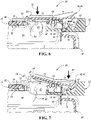
Figure 6 is a cross-sectional view of a portion of the crisper drawer taken along line 6-6 inFigure 1 with the cover plate of the humidity control system in the closed position; and -
Figure 7 is a cross-sectional view of the portion of the crisper drawer taken along line 6-6 inFigure 1 with the cover plate of the humidity control system in the open position. - Embodiments of the present disclosure are described herein. It is to be understood, however, that the disclosed embodiments are merely examples and other embodiments may take various and alternative forms. The figures are not necessarily to scale; some features could be exaggerated or minimized to show details of particular components. Therefore, specific structural and functional details disclosed herein are not to be interpreted as limiting, but merely as a representative basis for teaching one skilled in the art to variously employ the embodiments. As those of ordinary skill in the art will understand, various features illustrated and described with reference to any one of the figures may be combined with features illustrated in one or more other figures to produce embodiments that are not explicitly illustrated or described. The combinations of features illustrated provide representative embodiments for typical applications. Various combinations and modifications of the features consistent with the teachings of this disclosure, however, could be desired for particular applications or implementations.
- Referring to
Figure 1 , generally arefrigerator appliance 10 having a single door is illustrated. Therefrigerator 10 has a plurality ofwalls 12 that form ahousing 14. Thewalls 12 may include exterior panels and an internal liner. An insulating material, such as an insulating foam, may be disposed between the exterior panels and the internal liner of thewalls 12 in order reduce the heat transfer from the ambient surroundings and increase the efficiency of the refrigerator. Thewalls 12 may include a rear or back wall, a top wall, a bottom wall, and two side walls. The plurality ofwalls 12 and thehousing 14 define an internal cavity 16 and anopening 18 to the internal cavity 16. More specifically, adoor frame 20 may define theopening 18 to access the internal cavity 16. - The internal cavity 16 may be divided into a first internal storage chamber or fresh food compartment 22 and a second internal storage chamber or freezer compartment 24. The first internal storage chamber, fresh food compartment, or refrigerator compartment 22 may be configured to refrigerate and not freeze consumables within the fresh food compartment 22. The second internal storage chamber or a freezer compartment 24 may be configured to freeze consumables within the freezer compartment 24 during normal use.
- The
single door 26 ofrefrigerator 10 provides access to the interior volume of the refrigerator 10 (i.e., the internal cavity 16) where consumables may be stored. Thedoor 26 may be rotatably secured to thewalls 12 by one or more hinges. A secondary door orfreezer compartment door 28 may be disposed within the internal cavity 16 and over the freezer compartment 24 to provide a barrier between the freezer compartment 24 and the refrigerator compartment 22 within the internal cavity 16. Acrisper drawer 30 may be disposed within the refrigerator compartment 22. Thecrisper drawer 30 may more specifically be a drawer defining a storage space that is kept at a desired humidity that may be different from the remainder of the refrigerator compartment 22, but that is optimal for maintaining freshness of fruits and vegetables. Aframe 34 is configured to receive thecrisper drawer 30. Thecrisper drawer 30 may be slidable into and out of theframe 34. When thecrisper drawer 30 is within theframe 34, theframe 34 is disposed about or around thecrisper drawer 30. Anupper panel 36 that engages theframe 34 may be disposed along a top side ofcrisper drawer 30. Theupper panel 36 may form part of theframe 34. Theupper panel 36 may more specifically be a glass panel. - A venting or
humidity control system 38 for thecrisper drawer 30 is configured to vent air from thecrisper drawer 30 to an exterior of the crisper drawer 30 (e.g., the portion of the internal cavity 16 that is outside of the crisper drawer 30) to control the humidity within the crisper drawer. Thehumidity control system 38 may be integrated into the frame as illustrated or may be integrated directly into thecrisper drawer 30. One ormore shelves 32 may be secured to thewalls 12 within the refrigerator compartment 22 and to an internal surface of thedoor 26. - It is generally known that the freezer compartment 24 is typically kept at a temperature below the freezing point of water, and the refrigerator compartment 22 is typically kept at a temperature above the freezing point of water and generally below a temperature of from about 35° F. to about 50° F., and more typically below about 38° F.
- The
door 26 may include an exterior panel and an interior panel that is disposed on an internal side of the exterior panel of thedoor 26. The interior panel may be configured to face the internal cavity 16 when thedoor 26 is in a closed position. The interior panel of thedoor 26 may more specifically be a door liner. An insulating material, such as an insulating foam, may be disposed between the exterior panel and interior panel of thedoor 26 in order reduce the heat transfer from the ambient surroundings and increase the efficiency of therefrigerator 10. - The
refrigerator 10 includes one or more refrigeration loops (not shown) that are configured to cool the air the within the refrigerator compartment 22 and the freezer compartment 24. The refrigeration loop includes at least a compressor, an evaporator that cools air being delivered to the refrigerator compartment 22 and/or the freezer compartment 24, a condenser that rejects heat to ambient surroundings, and a thermal expansion valve. Fans may be utilized to direct air across the evaporator and the condenser to facilitate exchanging heat. The compressor and the fans may be connected to a controller. Sensors that measure the air temperature within the refrigerator compartment 22 and the freezer compartment 24 may be in communication with the controller. The controller may be configured to operate the compressor, fans, etc. in response to the air temperature within the within the refrigerator compartment 22 and the freezer compartment 24 being less than a threshold. - Such a controller may be part of a larger control system and may be controlled by various other controllers throughout the
refrigerator 10, and one or more other controllers can collectively be referred to as a "controller" that controls various functions of therefrigerator 10 in response to inputs or signals to control functions of therefrigerator 10. The controller may include a microprocessor or central processing unit (CPU) in communication with various types of computer readable storage devices or media. Computer readable storage devices or media may include volatile and nonvolatile storage in read-only memory (ROM), random-access memory (RAM), and keep-alive memory (KAM), for example. KAM is a persistent or non-volatile memory that may be used to store various operating variables while the CPU is powered down. Computer-readable storage devices or media may be implemented using any of a number of known memory devices such as PROMs (programmable read-only memory), EPROMs (electrically PROM), EEPROMs (electrically erasable PROM), flash memory, or any other electric, magnetic, optical, or combination memory devices capable of storing data, some of which represent executable instructions, used by the controller in controlling therefrigerator 10. - It should be understood that this disclosure should not be limited to the refrigerator configuration depicted in
Figure 1 but could apply to any type of refrigerator, such as a side-by-side type refrigerator, a two-door bottom mount type refrigerator, a top-mount type refrigerator, French-Door bottom mount type refrigerator, etc. Furthermore, it should be understood that the fresh food and freezer compartments may be accessible from the exterior of the refrigerator via separate doors. - Referring to
Figures 2-7 , thehumidity control system 38 for thecrisper drawer 30 is illustrated in Further detail. Theframe 34 defines at least oneorifice 40 that is configured to vent air from thecrisper drawer 30 to the exterior of thecrisper drawer 30 to control the humidity within thecrisper drawer 30. In the illustrated embodiment, theframe 34 defines threeorifices 40. However, it should be understood that the frame may define one or any number oforifices 40 that are configured to vent air from thecrisper drawer 30 to the exterior of thecrisper drawer 30. Acover plate 42 is pivotably secured to theframe 34 and is at least partially disposed over the at least oneorifice 40. Thecover plate 42 is configured to pivot relative to theframe 34 between a first or closed position 44 and a second or open position 46. - The
cover plate 42 is disposed over the at least oneorifice 40 to restrict air from flowing out of thecrisper drawer 30 when thecover plate 42 is in the closed position 44. The at least oneorifice 40 may have aproximal end 48 and adistal end 50. Agap 52 is defined between thedistal end 50 of the at least oneorifice 40 and thecover plate 42 such that air flows from thecrisper drawer 30 to the exterior of thecrisper drawer 30 via thegap 52 when thecover plate 42 is in the open position 46. More specifically, thegap 52 is in fluid communication with the at least oneorifice 40 and establishes fluid communication between the at least oneorifice 40 and the exterior of thecrisper drawer 30 such that air flows from thecrisper drawer 30 to the exterior of thecrisper drawer 30 via thegap 52 when thecover plate 42 is in the open position 46. Thegap 52 may be defined between anedge 54 of thecover plate 42 and thedistal end 50 of the at least oneorifice 40. - The
gap 52 increases in size when thecover plate 42 is pivoted from the closed position 44 to the open position 46 to facilitate air flow from thecrisper drawer 30 to the exterior of thecrisper drawer 30, which is illustrated byarrows 56 inFigures 3 and7 . Thegap 52 decreases in size when thecover plate 42 is pivoted from the open position 46 to the closed position 44 to restrict air flow from thecrisper drawer 30 to the exterior of thecrisper drawer 30, which is illustrated byarrow 58 inFigure 6 . More specifically,arrow 58 illustrates the airflow deflecting off of thecover plate 42 and being directed back into theinternal space 60 defined within thecrisper drawer 30. Thegap 52 may be completely closed off in the closed position 44 or may have a significant decrease in size relative to the open position 46 such that air flow from thecrisper drawer 30 to the exterior of thecrisper drawer 30 is zero or negligible. - The
frame 34 includes afirst protrusion 62 extending therefrom that defines a plurality ofscalloped notches 64. More specifically, thefirst protrusion 62 may extend upward from theframe 34. The frame also includes at least onepivot 66 disposed between the at least oneorifice 40 and thefirst protrusion 62. The at least onepivot 66 may comprise at least one horizontally oriented post. In the illustrated embodiment, theframe 34 includes two pivots 66. However, it should be understood that the frame may include one or any number ofpivots 66. - The
cover plate 42 is pivotably or rotatably secured to the at least onepivot 66 and is configured to transition between the closed position 44 and the open position 46 via rotation about the at least onepivot 66. More specifically, thecover plate 42 may include at least one C-shapedbushing 68 that is disposed and configured to rotate about the at least onepivot 66. Even more specifically, two C-shapedbushings 68 may engage the horizontally oriented posts that form thepivots 66 on opposing sides of an upright 70 that connects the horizontally oriented posts to theframe 34. The C-shapedbushings 68 may be configured flex outward and snap back to form an engagement between at least one C-shapedbushings 68 and the horizontally oriented post during installation of thecover plate 42 onto theframe 34. - The
cover plate 42 has afirst region 72 that is disposed over the at least oneorifice 40. Thecover plate 42 also has asecond region 74 that is disposed over thefirst protrusion 62. Thecover plate 42 has asecond protrusion 76 that extends from thesecond region 74. More specifically, thesecond protrusion 76 may extend downward from thecover plate 42 at thesecond region 74. - In the closed position 44, the
first region 72 covers the at least oneorifice 40 to restrict air from flowing out of thecrisper drawer 30. The second protrusion engages 76 a first of the scallopednotches 64 to retain thecover plate 42 in the closed position. In the open position 46, thegap 52 is defined between thedistal end 50 of the at least oneorifice 40 and thefirst region 72 such that air flows from thecrisper drawer 30 to the exterior of the crisper drawer via thegap 52. Thesecond protrusion 76 engages a second ofscalloped notches 64 to retain thecover plate 42 in the open position. As previously stated, the size of thegap 52 is increased in the open position 46 relative to the closed position 44. Also, as previously stated, thegap 52 may be completely closed off in the closed position 44 or may have a significant decrease in size relative to the open position 46 such that the air flow from thecrisper drawer 30 to the exterior of thecrisper drawer 30 is zero or negligible in the closed position 44. - The
second protrusion 76 is secured to thecover plate 42 via a biasingelement 78. The biasingelement 78 is configured to force thesecond protrusion 76 into engagement with the scallopednotches 64. During a transition of thecover plate 42 from the open position 46 to the closed position 44, which occurs when a downward force is applied to the first region 72 (e.g.,arrow 80 inFigure 6 ), thesecond protrusion 72 engages thefirst protrusion 62 between thescalloped notches 64 causing the biasingelement 78 to flex resulting in thesecond protrusion 72 being or forced out of the second ofscalloped notches 64 and allowing thecover plate 42 to transition to the closed position 44. Once thecover plate 42 has reached the closed position 44, the biasingelement 78 forces thesecond protrusion 72 into the first of the scallopednotches 64 to retain thecover plate 42 in the closed position 44. - During a transition of the
cover plate 42 from the closed position 44 to the open position 46, which occurs when a downward force is applied to the second region 74 (e.g.,arrow 82 inFigure 7 ), thesecond protrusion 72 engages thefirst protrusion 62 between thescalloped notches 64 causing the biasingelement 78 to flex resulting in thesecond protrusion 72 being or forced out of the first ofscalloped notches 64 and allowing thecover plate 42 to transition to the open position 46. Once thecover plate 42 has reached the open position 46, the biasingelement 78 forces thesecond protrusion 72 into the second of the scallopednotches 64 to retain thecover plate 42 in the open position 46. - A
top surface 84 of theframe 34 may define a recessedregion 86. The at least oneorifice 40 may be defined within the recessedregion 86. Thefirst protrusion 62 may be disposed within the recessedregion 86. The at least onepivot 66 may disposed within the recessedregion 86. Thecover plate 42 may be partially disposed within the recessedregion 86 and may be partially disposed above the recessedregion 86. - The
frame 34 may define aslot 88 that is configured to receive an end of theupper panel 36. Theframe 34 may include aprotrusion 90 that extends into theslot 88. Theupper panel 36 may define agrove 92. Theprotrusion 90 may engage thegroove 92 to retain the end of theupper panel 36 within theslot 88. - In an alternative embodiment all aspects the
humidity control system 38 may be defined by or connected to thecrisper drawer 30 as opposed to theframe 34. For example, all the details illustrated inFigure 4 may be defined by or connected to thecrisper drawer 30 and thecover plate 42 may be connected to thecrisper drawer 30. - It should be understood that the designations of first, second, third, fourth, etc. for any component, state, or condition described herein may be rearranged in the claims so that they are in chronological order with respect to the claims.
Claims (15)
- A refrigerator (10) comprising:a crisper drawer (30);a frame (34) configured to receive the crisper drawer (30), the frame (34) or the crisper drawer (30) defining at least one orifice (40) that is configured to vent air from the crisper drawer (30) to an exterior of the crisper drawer (30) to control a humidity within the crisper drawer (30); anda cover plate (42) secured to the frame (34) or the crisper drawer (30) and at least partially disposed over the at least one orifice (40), wherein (i) the cover plate (42) is configured to pivot relative to the frame (34) or the crisper drawer (30) between a first position (44) and a second position (46), (ii) in the first position (44) the cover plate (42) is disposed over the at least one orifice (40) to restrict air from flowing out of the crisper drawer (30), and (iii) in the second position (46) a gap (52) that is in fluid communication with the at least one orifice (40) is defined between a distal end (50) of the at least one orifice (40) and the cover plate (42) such that air flows from the crisper drawer (30) to the exterior of the crisper drawer (30) via the gap (52).
- The refrigerator (10) of claim 1, wherein the frame (34) or the crisper drawer (30) has a first protrusion (62) extending therefrom that defines a plurality of scalloped notches (64).
- The refrigerator (10) of claim 2, wherein the cover plate (42) has a second protrusion (76) extending downward therefrom.
- The refrigerator (10) of claim 3, wherein the second protrusion (76) is configured to engage a first of scalloped notches (64) to retain the cover plate (42) in the first position (44).
- The refrigerator (10) of claim 4, wherein second protrusion (76) is configured to engage a second of scalloped notches (64) to retain the cover plate (42) in the second position (46).
- The refrigerator (10) of claim 5 further comprising a biasing element (78) that biases the second protrusion (76) into engagement with the scalloped notches (64).
- The refrigerator (10) of claim 5, wherein the first protrusion (62) and the at least one orifice (40) are disposed on opposing sides of a pivot point of the cover plate (42).
- The refrigerator (10) of claim 5, wherein the cover plate (42) includes a first region (72) disposed over the at least one orifice (40) and a second region (74) disposed over the first protrusion (62).
- The refrigerator (10) of claim 8, wherein in the first position (44) the first region (72) covers the at least one orifice (40) to restrict air from flowing out of the crisper drawer (30).
- The refrigerator (10) of claim 8, wherein in the second position (46) the gap (52) is defined between the distal end (50) of the at least one orifice (40) and the first region (72) such that air flows from the crisper drawer (30) to the exterior of the crisper drawer (30) via the gap (52).
- The refrigerator (10) of claim 1, wherein the cover plate (42) is pivotally secured to the frame (34) or the crisper drawer (30) via a C-shaped bushing (68) that engages a horizontally oriented post (66).
- The refrigerator (10) of claim 11, wherein one of the C-shaped bushing (68) and the horizontally oriented post (66) is secured to the cover plate (42) and the other of the C-shaped bushing (68) and the horizontally oriented post (66) is secured to the frame (34) or the crisper drawer (30).
- The refrigerator (10) of claim 1, wherein a top surface (84) of the frame (34) or the crisper drawer (30) defines a recessed region (86).
- The refrigerator (10) of claim 13, wherein the cover plate (42) is partially disposed within the recessed region (86) and is partially disposed above the recessed region (86).
- The refrigerator (10) of claim 13, wherein the at least one orifice (40) is defined within the recessed region (86).
Applications Claiming Priority (1)
| Application Number | Priority Date | Filing Date | Title |
|---|---|---|---|
| US17/373,109 US11703267B2 (en) | 2021-07-12 | 2021-07-12 | Refrigerator appliance |
Publications (1)
| Publication Number | Publication Date |
|---|---|
| EP4119869A1 true EP4119869A1 (en) | 2023-01-18 |
Family
ID=81580956
Family Applications (1)
| Application Number | Title | Priority Date | Filing Date |
|---|---|---|---|
| EP22171700.2A Withdrawn EP4119869A1 (en) | 2021-07-12 | 2022-05-04 | Refrigerator appliance |
Country Status (2)
| Country | Link |
|---|---|
| US (1) | US11703267B2 (en) |
| EP (1) | EP4119869A1 (en) |
Citations (8)
| Publication number | Priority date | Publication date | Assignee | Title |
|---|---|---|---|---|
| DE69719121T2 (en) * | 1996-07-26 | 2003-10-16 | Dart Industries, Inc. | Ventilation arrangement with ventilation flap lid |
| US20060005567A1 (en) * | 2002-10-23 | 2006-01-12 | Lg Electronics Inc. | Vegetable room for refrigerator |
| CN1982820A (en) * | 2005-12-16 | 2007-06-20 | 海尔集团公司 | Air-cooled drawer with air outlet for refrigerator |
| KR20090133008A (en) * | 2008-06-23 | 2009-12-31 | 엘지전자 주식회사 | Refrigerator with adjusting member |
| US20180265263A1 (en) * | 2017-03-14 | 2018-09-20 | Ningbo Lisi Houseware Co., Ltd. | Touch and seal self-closing container |
| DE102019214589A1 (en) * | 2019-09-24 | 2021-03-25 | BSH Hausgeräte GmbH | Food receptacle with support rail, in which a flap is movably mounted, as well as household refrigeration device |
| DE102019214597A1 (en) * | 2019-09-24 | 2021-03-25 | BSH Hausgeräte GmbH | Food receptacle with specific ventilation device with pre-assembly, as well as household refrigeration device and method |
| DE102019214595A1 (en) * | 2019-09-24 | 2021-03-25 | BSH Hausgeräte GmbH | Food receptacle with a specially shaped flap of a ventilation device, as well as a household refrigerator |
Family Cites Families (10)
| Publication number | Priority date | Publication date | Assignee | Title |
|---|---|---|---|---|
| US4557118A (en) | 1984-12-06 | 1985-12-10 | Amana Refrigeration, Inc. | Crisper humidity control |
| KR970001442Y1 (en) | 1992-01-27 | 1997-03-06 | 이헌조 | Humidity control device of a refrigerator |
| WO2014154563A1 (en) * | 2013-03-29 | 2014-10-02 | BSH Bosch und Siemens Hausgeräte GmbH | A home appliance keeping produce as fresh for a long time and a method used in the home appliance |
| DE102015222229A1 (en) | 2015-11-11 | 2017-05-11 | BSH Hausgeräte GmbH | Domestic refrigerating appliance with a freshness container whose front wall is an outer wall of the device |
| CN105546927B (en) | 2016-01-15 | 2018-02-02 | 青岛海尔股份有限公司 | Drawer appliance and the refrigerator with the drawer appliance |
| CN105605866B (en) | 2016-01-15 | 2018-07-13 | 青岛海尔股份有限公司 | Drawer appliance, the refrigerator with the drawer appliance |
| BR112019011838B1 (en) * | 2016-12-19 | 2022-12-27 | Aktiebolaget Electrolux | REFRIGERATOR DRAWER FOR FOOD PRESERVATION AND REPLACEABLE MEMBRANE |
| CN107131711B (en) | 2017-05-19 | 2019-07-26 | 合肥华凌股份有限公司 | Refrigerator humidity regulation drawer appliance and refrigerator |
| TR201712278A1 (en) | 2017-08-17 | 2019-03-21 | Arcelik As | MOISTURE CONTROLLED REFRIGERATOR WITH VEGETABLES |
| CN111197897B (en) | 2020-03-09 | 2022-01-07 | 海信(山东)冰箱有限公司 | A kind of refrigerator |
-
2021
- 2021-07-12 US US17/373,109 patent/US11703267B2/en active Active
-
2022
- 2022-05-04 EP EP22171700.2A patent/EP4119869A1/en not_active Withdrawn
Patent Citations (8)
| Publication number | Priority date | Publication date | Assignee | Title |
|---|---|---|---|---|
| DE69719121T2 (en) * | 1996-07-26 | 2003-10-16 | Dart Industries, Inc. | Ventilation arrangement with ventilation flap lid |
| US20060005567A1 (en) * | 2002-10-23 | 2006-01-12 | Lg Electronics Inc. | Vegetable room for refrigerator |
| CN1982820A (en) * | 2005-12-16 | 2007-06-20 | 海尔集团公司 | Air-cooled drawer with air outlet for refrigerator |
| KR20090133008A (en) * | 2008-06-23 | 2009-12-31 | 엘지전자 주식회사 | Refrigerator with adjusting member |
| US20180265263A1 (en) * | 2017-03-14 | 2018-09-20 | Ningbo Lisi Houseware Co., Ltd. | Touch and seal self-closing container |
| DE102019214589A1 (en) * | 2019-09-24 | 2021-03-25 | BSH Hausgeräte GmbH | Food receptacle with support rail, in which a flap is movably mounted, as well as household refrigeration device |
| DE102019214597A1 (en) * | 2019-09-24 | 2021-03-25 | BSH Hausgeräte GmbH | Food receptacle with specific ventilation device with pre-assembly, as well as household refrigeration device and method |
| DE102019214595A1 (en) * | 2019-09-24 | 2021-03-25 | BSH Hausgeräte GmbH | Food receptacle with a specially shaped flap of a ventilation device, as well as a household refrigerator |
Also Published As
| Publication number | Publication date |
|---|---|
| US20230009966A1 (en) | 2023-01-12 |
| US11703267B2 (en) | 2023-07-18 |
Similar Documents
| Publication | Publication Date | Title |
|---|---|---|
| KR101659622B1 (en) | Method for controlling of refrigerator | |
| CN105814378B (en) | Refrigerator | |
| US20060156755A1 (en) | Methods and apparatus for operating a refrigerator | |
| EP4067785A1 (en) | Refrigerator appliance | |
| US11460241B1 (en) | Refrigerator and shelving system for a refrigerator | |
| US11703267B2 (en) | Refrigerator appliance | |
| US11920851B2 (en) | Refrigerator appliance | |
| US11713917B2 (en) | Refrigerator appliance with self-adjusting mullion | |
| US11549743B1 (en) | Refrigerator appliance | |
| EP4242564A1 (en) | Refrigerator and storage system for a refrigerator | |
| EP4361539A1 (en) | Refrigerator and mullion for a refrigerator | |
| EP4177553A1 (en) | Drawer-shelf system for a refrigerator appliance | |
| US12181208B2 (en) | Refrigerator appliance subcomponent mounting system | |
| US20240410644A1 (en) | Refrigerator appliance subcomponent mounting system | |
| US20240255211A1 (en) | Refrigerator appliance subcomponent mounting system | |
| US20260029188A1 (en) | Refrigerator appliance | |
| US12281838B2 (en) | Refrigerator appliance | |
| US20250164174A1 (en) | Refrigerator appliance | |
| US12146703B2 (en) | Refrigerator appliance | |
| US12492859B2 (en) | Refrigerator appliance subcomponent mounting system | |
| US11441835B1 (en) | Refrigerator appliance and containment system for contents of refrigerator appliance | |
| KR100678777B1 (en) | Refrigerator | |
| US20230408183A1 (en) | Shelving system for a refrigerator | |
| US20260043604A1 (en) | Refrigerator and storage system for a refrigerator | |
| US20250362074A1 (en) | Bin storage system for a refrigerator appliance |
Legal Events
| Date | Code | Title | Description |
|---|---|---|---|
| PUAI | Public reference made under article 153(3) epc to a published international application that has entered the european phase |
Free format text: ORIGINAL CODE: 0009012 |
|
| STAA | Information on the status of an ep patent application or granted ep patent |
Free format text: STATUS: THE APPLICATION HAS BEEN PUBLISHED |
|
| AK | Designated contracting states |
Kind code of ref document: A1 Designated state(s): AL AT BE BG CH CY CZ DE DK EE ES FI FR GB GR HR HU IE IS IT LI LT LU LV MC MK MT NL NO PL PT RO RS SE SI SK SM TR |
|
| RAP3 | Party data changed (applicant data changed or rights of an application transferred) |
Owner name: WHIRLPOOL CORPORATION |
|
| STAA | Information on the status of an ep patent application or granted ep patent |
Free format text: STATUS: REQUEST FOR EXAMINATION WAS MADE |
|
| 17P | Request for examination filed |
Effective date: 20230718 |
|
| RBV | Designated contracting states (corrected) |
Designated state(s): AL AT BE BG CH CY CZ DE DK EE ES FI FR GB GR HR HU IE IS IT LI LT LU LV MC MK MT NL NO PL PT RO RS SE SI SK SM TR |
|
| P01 | Opt-out of the competence of the unified patent court (upc) registered |
Effective date: 20230821 |
|
| GRAP | Despatch of communication of intention to grant a patent |
Free format text: ORIGINAL CODE: EPIDOSNIGR1 |
|
| STAA | Information on the status of an ep patent application or granted ep patent |
Free format text: STATUS: GRANT OF PATENT IS INTENDED |
|
| STAA | Information on the status of an ep patent application or granted ep patent |
Free format text: STATUS: THE APPLICATION HAS BEEN WITHDRAWN |
|
| INTG | Intention to grant announced |
Effective date: 20250326 |
|
| 18W | Application withdrawn |
Effective date: 20250402 |