EP4119850A1 - Cooking appliance and heating control method - Google Patents
Cooking appliance and heating control method Download PDFInfo
- Publication number
- EP4119850A1 EP4119850A1 EP22183144.9A EP22183144A EP4119850A1 EP 4119850 A1 EP4119850 A1 EP 4119850A1 EP 22183144 A EP22183144 A EP 22183144A EP 4119850 A1 EP4119850 A1 EP 4119850A1
- Authority
- EP
- European Patent Office
- Prior art keywords
- food
- heating
- present
- heating chamber
- front door
- Prior art date
- Legal status (The legal status is an assumption and is not a legal conclusion. Google has not performed a legal analysis and makes no representation as to the accuracy of the status listed.)
- Pending
Links
Images




Classifications
-
- F—MECHANICAL ENGINEERING; LIGHTING; HEATING; WEAPONS; BLASTING
- F24—HEATING; RANGES; VENTILATING
- F24C—DOMESTIC STOVES OR RANGES ; DETAILS OF DOMESTIC STOVES OR RANGES, OF GENERAL APPLICATION
- F24C7/00—Stoves or ranges heated by electric energy
- F24C7/08—Arrangement or mounting of control or safety devices
- F24C7/082—Arrangement or mounting of control or safety devices on ranges, e.g. control panels, illumination
- F24C7/085—Arrangement or mounting of control or safety devices on ranges, e.g. control panels, illumination on baking ovens
Definitions
- the present invention relates to a cooking appliance that heats a food placed inside a heating chamber, and a heating control method.
- a cooking appliance disclosed in Patent Document 1 includes a detection sensor (a floodlighting element and a light receiving element) for detecting a food in a cooking chamber.
- the floodlighting element and the light receiving element are provided on left and right side walls as viewed from the opening side of the cooking chamber, which is opened and closed with a door, respectively.
- light is emitted from the floodlighting element provided on one side wall toward the light receiving element oppositely provided on the other side wall, so as to detect the presence or absence of a food in or from the cooking chamber based on the amount of light received by the light receiving element.
- an exterior light may enter the light receiving element arranged on the side wall and increase the amount of light received by the light receiving element, so that it is feared that, although present in the cooking chamber, the food is not determined to be present, and cooking is not automatically started when the door is closed. If a mistaken detection of the food occurs under the influence of the exterior light or the like, it is highly possible that cooking is not automatically started even when the door is closed again after being opened to make sure of the food in the cooking chamber, so that cooking needs to be manually started.
- An aspect of the present invention is aimed at achieving a cooking appliance allowing the time and effort taken up to the start of cooking of the food to be reduced even if the exterior light affects the detection of the food.
- a cooking appliance includes a heating chamber, a door provided on the heating chamber, an opening and closing detector that detects opening and closing of the door, a determiner that determines whether a food is present in the heating chamber, a reader that reads an information code for cooking the food, and a heating controller that performs heating control on the food in the heating chamber based on the information code read by the reader.
- the heating controller starts the heating of the food if the opening and closing detector detects that the door is closed and the determiner determines that the food is present in the heating chamber.
- a heating control method for a cooking appliance is a heating control method for a cooking appliance including: a heating chamber; a door provided on the heating chamber; an opening and closing detector that detects opening and closing of the door; a determiner that determines whether a food is present in the heating chamber; a reader that reads an information code for cooking the food; and a heating controller that performs heating control on the food in the heating chamber based on the information code read by the reader.
- the heating control method includes starting the heating of the food with the heating controller if the opening and closing detector detects that the door is closed and the determiner determines that the food is present in the heating chamber.
- the time and effort taken up to the start of cooking of a food are reduced even if the exterior light affects the detection of the food.
- FIG. 1 is a perspective view of a cooking appliance 1 of the present embodiment, with a front door 12 that is openable and is provided on a body of the cooking appliance 1 being closed, as obliquely viewed from an upper front.
- FIG. 2 is a front view of the cooking appliance 1 illustrated in FIG. 1 , with the front door 12 being opened.
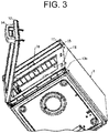
- FIG. 3 is a perspective view of the cooking appliance 1 illustrated in FIG. 1 , with the front door 12 being opened, as obliquely viewed from a lower right.
- the cooking appliance 1 is a microwave oven, for instance, and is provided with an operation panel 11 in an upper front portion and the front door 12 below the operation panel 11.
- the front door 12 is a door for opening and closing a heating chamber 13 provided in rear of the front door 12 and is closed so as to cover a front opening 13b of the heating chamber 13.
- the front door 12 is a laterally openable door that revolves about an edge on a user's left, and is provided with a handle 14 in the vicinity of a right edge opposite to the edge as the center of revolution.
- a food sensor 31 is provided on a side wall 13a in the heating chamber 13. It is detected by the food sensor 31 that a food is or is not placed on a flat plate 13c provided on a bottom face in the heating chamber 13. In other words, the food sensor 31 detects presence or absence of a food in or from the heating chamber 13.
- the food sensor 31 is constituted of a light emitting element 31a arranged on the side wall 13a on the right as viewed from the front opening 13b as well as a first light receiving element 31b and a second light receiving element 31c both arranged on the side wall 13a on the left.
- the food sensor 31 is thus a so-called transmission type photosensor, and receives the light, which is emitted from the light emitting element 31a, with the first light receiving element 31b and the second light receiving element 31c arranged on an opposite face.
- the food sensor 31 will be detailed later.
- the operation panel 11 is provided on a front face of a control frame 15.
- the operation panel 11 is provided so that a front face of the operation panel 11 may substantially be flush with a front face of the front door 12 in a front and rear direction of the cooking appliance 1.
- control board (not illustrated) exerting such functions as control of a display 30 of the operation panel 11 and acceptance of user operation to an input key and the like is provided.
- FIG. 4 is a vertical cross-sectional view of the control frame 15, illustrating a state of installation of a reader 16.
- FIG. 5 is a diagram illustrating a reading region 19 of the reader 16.
- the control frame 15 is so provided as to protrude in front of the cooking appliance 1.
- the reader 16 is mounted on the underside of a reader board (circuit board) 17 and provided as such in a lower portion of the interior of the control frame 15.
- the reader board 17 includes a drive circuit for the reader 16.
- the reader 16 is so provided as to be installed in a position above the front opening 13b of the heating chamber 13 outside the heating chamber 13 and to have the reading region 19 below the position of installation.
- the reader 16 is a barcode reader, for instance, and is to read an information code (barcode, for instance) imparted to a food to be heated in the cooking appliance 1 or a container of the food.
- the reading region 19 of the reader 16 is a region below the reader 16 as illustrated in FIG. 5 , and the control frame 15 is provided with a transparent reading window 18 in a bottom portion opposite to the reader 16.
- the reading region 19 of the reader 16 is shown by a red light, for instance, so that a user may visually recognize the reading region 19.
- the red light is emitted by a reading region illuminator 21 (see FIG. 10 ).
- a red light emitting diode used as the reading region illuminator 21 is a red light emitting diode (red LED), for instance.
- the light showing the reading region 19 is not limited to the red light but may be other light visible to the user, such as a laser light.
- the number of red LEDs may be one or more.
- the reader 16 is provided in a central portion in a width direction (lateral direction) of the front opening 13b of the heating chamber 13, as seen from FIGS. 2 and 3 .
- FIG. 6 is a diagram illustrating examples of the information code, that is to say, illustrating an exemplary information code constituted of a two-dimensional code (Quick Response (QR) Code (registered trademark)) with a reference sign 1061, and an exemplary information code constituted of a one-dimensional barcode with a reference sign 1062.
- QR Quality Response
- the information code is used for cooking a food.
- the information code includes information indicating the kind of a food and information (heating information) indicating conditions for cooking the food, whose kind is indicated.
- the heating information is information required for cooking, and contains the heating time and the wattage of high frequency power in the cooking appliance 1.
- the information code includes the information indicating the kind of a food, that is to say, indicating whether the food is a boxed meal or a rice ball (or further indicating the kind of the boxed meal or the rice ball), for instance, and the heating information containing the heating time and wattage of high frequency power corresponding to the food, whose kind is indicated.
- the information code is imparted to a food or a container of the food by printing or with a sticker, for instance. Since the information code is used for cooking a specified food, the information code may only include information specifying a food and the heating information on the specified food may be acquired from an external server, or a server 51 ( FIG. 10 ). The information code may only include the heating information on a food.
- the information code may be a two-dimensional code such as illustrated in FIG. 6 with the reference sign 1061 or a one-dimensional barcode such as illustrated in FIG. 6 with the reference sign 1062.
- the information code is not particularly limited to the barcode or the like as long as the information code is capable of indicating the kind of a food.
- FIG. 7 is a diagram illustrating an exemplary arrangement of the light emitting element 31a, the first light receiving element 31b, and the second light receiving element 31c constituting the food sensor 31 in the cooking appliance 1 illustrated in FIG. 1 , and a sensor detection area 32 (a first detection area 32a and a second detection area 32b) of the food sensor 31.
- FIG. 7 has a part with a reference sign 1071 illustrating the heating chamber 13 as viewed from the top face side, and a part with a reference sign 1072 illustrating the heating chamber 13 as viewed from the front opening 13b side.
- FIG. 8 is a circuit diagram illustrating an equivalent circuit of the food sensor 31.
- FIG. 9 is a diagram for explaining a method for determining whether a food is present with the food sensor 31.
- the light emitting element 31a is constituted of a near infrared LED
- the first light receiving element 31b and the second light receiving element 31c are each constituted of a phototransistor (receiving light at a wavelength of 900 nm).
- the first and second light receiving elements 31b and 31c receive a near infrared light emitted by the light emitting element 31a.
- the equivalent circuit of the food sensor 31 is as illustrated in FIG. 8 .
- the light emitting element 31a is provided in a nearly central position on the side wall 13a on the right in the heating chamber 13 as illustrated in the part with the reference sign 1071 of FIG. 7 , which position is at a height H1 (of 15 mm in the illustrated example) from the flat plate 13c on the bottom face of the heating chamber 13 as illustrated in the part with the reference sign 1072 of FIG. 7 .
- the first light receiving element 31b and the second light receiving element 31c are provided in the positions, which are separated from a straight line extending from the light emitting element 31a to the side wall 13a on the opposite side at specified distances, respectively, as illustrated in the part with the reference sign 1071 of FIG.
- the height H2 at which the first and second light receiving elements 31b and 31c are provided, is identical to the height H1, at which the light emitting element 31a is provided.
- a specified region including a light emission region extending from the light emitting element 31a emitting the near infrared light to the first light receiving element 31b receiving the emitted near infrared light is assumed as the first detection area 32a for food detection
- a specified region including a light emission region extending from the light emitting element 31a emitting the near infrared light to the second light receiving element 31c receiving the emitted near infrared light is assumed as the second detection area 32b for food detection.
- the first and second detection areas 32a and 32b constitute the sensor detection area 32 on the flat plate 13c of the heating chamber 13.
- the food sensor 31 transmits light reception signals indicating the reception of light by the first light receiving element 31b and the second light receiving element 31c to a controller 22 ( FIG. 10 ) of the cooking appliance 1.
- the controller 22 determines whether a food is present in the heating chamber 13 from the light reception signals as transmitted.
- the output voltage (Vout 1) of the first light receiving element 31b and the output voltage (Vout 2) of the second light receiving element 31c are each higher than 4.0 V in a state where no foods are certainly present on the flat plate 13c of the heating chamber 13.
- the output voltage of a light receiving element is lower than 0.6 V if a food is present in the sensor detection area 32 on the flat plate 13c of the heating chamber 13, and the output voltage of a light receiving element is higher than 4.0 V if no foods are present in the sensor detection area 32.
- the values of the first threshold voltage (Vth 1) and the second threshold voltage (Vth 2) are not limited to 0.6 V and 4.0 V, respectively, but changed appropriately to the specifications of the light emitting element 31a as well as the first and second light receiving elements 31b and 31c, and the like.
- the output voltage of a light receiving element may be equal to or higher than 0.6 V but not higher than 4.0 V if the food is not appropriately placed in the sensor detection area 32 (if the food only occupies part of the sensor detection area 32), if the food (or the container thereof) is of a high transparency, if the food is placed indeed in the sensor detection area 32 but under the influence of an exterior light, and so forth. In other words, it is difficult to determine whether a food is certainly placed in the heating chamber 13, if the output voltage of a light receiving element is equal to or higher than 0.6 V but not higher than 4.0 V.
- the controller 22 determines that no foods are present if either of the output voltage (Vout 1) of the first light receiving element 31b and the output voltage (Vout 2) of the second light receiving element 31c is equal to or higher than 0.6 V but not higher than 4.0 V. As a result, heating is only performed if a food is certainly present in the heating chamber 13, leading to the suppression of no-load operation.
- the determinations as above are implemented by a determination unit 22a of the controller 22 to be described later. The determination unit 22a will be detailed later.
- FIG. 10 is a functional block diagram of a control device included in the cooking appliance 1.
- the control device includes the controller 22, which controls operations of the cooking appliance 1.
- the controller 22 is constituted of a microcomputer, for instance, and has a central processing unit (CPU), a read-only memory (ROM), and a random access memory (RAM).
- CPU central processing unit
- ROM read-only memory
- RAM random access memory
- the controller 22 is connected with the operation panel 11, a heating operation section 23, the reader 16, the reading region illuminator 21, a reading result notifier 24, the food sensor 31, a front door opening and closing detector (opening and closing detector) 25, and a memory (storage) 52.
- the front door opening and closing detector 25 is constituted of, for instance, a switch that turns on when the front door 12 is closed, and detects an opened state and a closed state of the front door 12. The result of detection by the front door opening and closing detector 25 is sent to the controller 22.
- the heating operation section 23 is an operation section for heating a food placed in the heating chamber 13, such as a microwave output device or a heater.
- the reading result notifier 24 is a buzzer or a sound generator, and is controlled by the controller 22 so as to notify the user of the success or failure in reading of the information code by the reader 16.
- the controller 22 controls the heating operation section 23 so that the food may be heated in accordance with the heating information as acquired through the reading of the information code by the reader 16.
- a variety of heating information corresponding to various kinds of foods may previously be registered in the server 51, and the controller 22 may acquire, from the server 51, heating information corresponding to the kind of a food acquired through the reading of the information code by the reader 16.
- the cooking appliance 1 in itself may have the heating information corresponding to the kind of a food. In that case, the cooking appliance 1 does not need to communicate with the server 51.
- the controller 22 includes the determination unit 22a, which determines whether a food is present in the heating chamber 13 based on a detection result sent from the food sensor 31, a heating control unit 22b for controlling a heating operation of the heating operation section 23 based on a determination result of the determination unit 22a, and a reading control unit 22c for controlling a reading operation of the reader 16 based on the determination result of the determination unit 22a.
- the food sensor 31 is a sensor for detecting a food in the heating chamber 13, and includes the light emitting element 31a (light emitter), which emits light, and the first and second light receiving elements 31b and 31c (light receiver), which receive the light as emitted from the light emitting element 31a.
- the light emitting element 31a light emitter
- the first and second light receiving elements 31b and 31c light receiver
- the determination unit 22a determines whether a food is present in the heating chamber 13, according to the output voltage of the first light receiving element 31b and the second light receiving element 31c (namely, the amount of light received by the first light receiving element 31b and the second light receiving element 31c) of the food sensor 31. Specifically, the determination unit 22a determines whether a food is present in the heating chamber 13 based on a signal indicating the detection result sent from the food sensor 31 (the output voltage of the first light receiving element 31b and the second light receiving element 31c).
- a specific method for determining whether a food is present is as follows: If a food is placed in the sensor detection area 32, the light emitted by the light emitting element 31a of the food sensor 31 decreases before being received by the first light receiving element 31b and the second light receiving element 31c. Consequently, the output voltage of the first light receiving element 31b and the second light receiving element 31c is reduced. If such output voltage has a value lower than a preset value (Vth 1 in FIG. 9 ), it is determined that a food is present. If no foods are placed in the sensor detection area 32, the light emitted by the light emitting element 31a of the food sensor 31 decreases indeed before being received by the first light receiving element 31b and the second light receiving element 31c but with a small degree of decrease.
- the output voltage of the first light receiving element 31b and the second light receiving element 31c is not lower than that when it is determined that a food is present. If such output voltage has a value equal to or higher than a preset value (Vth 1 or Vth 2 in FIG. 9 ), it is determined that no foods are present.
- the heating control unit 22b permits the heating operation of the heating operation section 23 if the detection result of the front door opening and closing detector 25 as sent to the controller 22 is that the front door 12 is closed and the determination result of the determination unit 22a is that a food is present in the heating chamber 13, and does not permit the heating operation of the heating operation section 23 if the determination result is that no foods are present in the heating chamber 13.
- the operations of the cooking appliance 1 are described below.
- a food is assumed as a packed lunch with an information code imparted to an upper face of its container, and description is made on the case, where the packed lunch is heated with the cooking appliance 1.
- the user recognizes a guidance indication 20 ("open the door and expose the information code to the red light", for instance) on the operation panel 11. Then, the user opens the front door 12 in accordance with the guidance indication 20. If the front door opening and closing detector 25 detects the opened state of the front door 12, the controller 22 causes the reader 16 and the reading region illuminator 21 to operate.
- the user moves the packed lunch so that the information code may be in the reading region 19 of the reader 16 (the red light may hit the information code), in accordance with the guidance indication 20 on the operation panel 11.
- the reader 16 reads the information code imparted to the packed lunch. If the reader 16 successfully reads the information code, the controller 22 causes the reading result notifier 24 to notify the user of the reading result. At this time, the reading result notifier 24 operates to generate either or both of a continuous beeping sound and a voice saying "reading of the information code succeeded".
- the determination unit 22a determines whether the packed lunch to be heated is placed in a specified position in the heating chamber 13. If it is determined by the determination unit 22a that the packed lunch is present in the heating chamber 13, the determination result is sent to the heating control unit 22b. On the other hand, the front door opening and closing detector 25 sends, to the heating control unit 22b, a detection signal indicating that the front door 12 is closed. As a result, heating control by the heating control unit 22b, namely, the heating operation of the heating operation section 23 is permitted and heating of the packed lunch is started.
- the user is notified of the completion of heating of the packed lunch and takes the packed lunch out of the heating chamber 13. If the packed lunch is taken out of the heating chamber 13 and, accordingly, lost from the sensor detection area 32 in the heating chamber 13, a signal received by the food sensor 31 has a reference value, so that the determination unit 22a of the controller 22 determines that the packed lunch is not present in the heating chamber 13. Based on this determination result (that the packed lunch is not placed in the heating chamber 13) of the determination unit 22a, the heating control unit 22b does not permit the heating operation of the heating operation section 23. Consequently, the heating operation section 23 does not perform the heating operation in the state, where the packed lunch is not placed in the heating chamber 13. In other words, the heating operation is not performed in a no-load state.
- FIG. 11 is a flowchart illustrating a flow of processing up to the start of cooking in the cooking appliance 1 (heating control method).
- step S11 front door opening and closing detection is performed (step S11).
- step S11 the opening or closing of the front door 12 is detected by the front door opening and closing detector 25 and the detection result is sent to the determination unit 22a and the heating control unit 22b.
- step S12 determines whether the front door 12 is closed.
- step S12 the determination unit 22a determines whether the front door 12 is closed from the detection result of the front door opening and closing detector 25. If it is determined by the determination unit 22a that the front door 12 is closed (YES in step S12), the processing proceeds to step S13 so as to perform the food detection.
- the method for detecting a food is described above with reference to FIGS. 8 and 9 , so that no description is made on such method here.
- step S13 the food detection is performed by the food sensor 31 and the detection result is sent to the determination unit 22a.
- the determination unit 22a determines whether a food is present (step S14).
- step S14 the determination unit 22a determines whether a food is present from the detection result sent from the food sensor 31.
- the detection result of the food sensor 31 is represented as a value of the output voltage of the first light receiving element 31b and the second light receiving element 31c.
- the determination unit 22a determines whether a food is present in the heating chamber 13 from the value of the output voltage and sends the determination result that a food is present (YES in step S14) to the heating control unit 22b so as to start the heating (step S15).
- step S15 the heating control unit 22b allows the control of the heating operation section 23 if the detection result sent from the front door opening and closing detector 25 is that the front door 12 is closed and the determination result sent from the determination unit 22a is that a food is present.
- the determination unit 22a sends the determination result to the heating control unit 22b and the heating control unit 22b does not allow the control of the heating operation section 23. As a result, the processing ends because a food as a heating control target is not present.
- the heating control unit 22b does not allow the control of the heating operation section 23 solely with the detection result that the front door 12 is closed, but allows the control of the heating operation section 23 with both of the detection result that the front door 12 is closed and the determination result that a food is present.
- the heating control is performed if the result of such determination is that a food is placed in the heating chamber 13.
- the heating control is performed if the result of such determination is that a food is placed in the heating chamber 13.
- the information code is read so as to acquire the heating information on a food in advance and the heating control is performed on the food immediately after the front door 12 is closed, as in the above cooking appliance 1, in particular, it is possible to unfailingly perform the heating control when a food is present, by determining after the front door 12 is closed whether a food is present.
- the heating of a food is to be automatically started if it is determined that a food is present in the state, where the door of the heating chamber is closed.
- the time and effort taken up to the start of cooking of a food are reduced even if the exterior light affects the detection of the food.
- a cooking appliance 1 is the same as the cooking appliance 1 of the first embodiment but processing up to the start of the heating control is different from that in the first embodiment. In other words, control by the controller 22 is different from that in the first embodiment.
- FIG. 12 is a flowchart illustrating a flow of processing up to the start of cooking in the present embodiment.
- step S21 front door opening and closing detection is performed (step S21).
- step S21 the opening or closing of the front door 12 is detected by the front door opening and closing detector 25 and the detection result is sent to the determination unit 22a and the heating control unit 22b.
- step S22 the determination unit 22a determines whether the front door 12 is opened.
- step S22 the determination unit 22a determines whether the front door 12 is opened from the detection result of the front door opening and closing detector 25. If it is determined by the determination unit 22a that the front door 12 is opened (YES in step S22), the processing proceeds to step S23 so as to perform the food detection.
- the method for detecting a food is described above with reference to FIGS. 8 and 9 , so that no description is made on such method here.
- step S23 the food detection is performed by the food sensor 31 and the detection result is sent to the determination unit 22a.
- the determination unit 22a determines whether any food is absent (step S24).
- step S24 the result of detection by the food sensor 31 is sent to the determination unit 22a and the determination unit 22a determines whether a food is present. If the determination unit 22a determines that any food is absent (YES in step S24), the front door opening and closing detector 25 performs the front door opening and closing detection (step S25). In step S25, the opening or closing of the front door 12 is detected by the front door opening and closing detector 25 and the detection result is sent to the determination unit 22a and the heating control unit 22b. If the determination unit 22a determines that a food is present (NO in step S24), the processing returns to step S23 so as to perform the food detection.
- step S26 the determination unit 22a determines whether the front door 12 is closed.
- step S26 the determination unit 22a determines whether the front door 12 is closed from the detection result of the front door opening and closing detector 25. If it is determined by the determination unit 22a that the front door 12 is closed (YES in step S26), the processing proceeds to step S27 so as to perform the food detection. If it is determined by the determination unit 22a that the front door 12 is opened (NO in step S26), the processing returns to step S25 so as to perform the front door opening and closing detection.
- step S27 the food detection is performed by the food sensor 31 and the detection result is sent to the determination unit 22a.
- the determination unit 22a determines whether a food is present (step S28).
- step S28 the determination unit 22a determines whether a food is present based on the detection result sent from the food sensor 31.
- the determination unit 22a sends the determination result that a food is present (YES in step S28) to the heating control unit 22b.
- the heating control unit 22b starts the heating based on the determination result from the determination unit 22a that a food is present (step S29).
- the heating control unit 22b allows the control of the heating operation section 23 if the detection result sent from the front door opening and closing detector 25 is that the front door 12 is closed and the determination result sent from the determination unit 22a is that a food is present.
- the heating control unit 22b starts the heating of a food if it is detected by the front door opening and closing detector 25 that the front door 12 is closed and it is determined by the determination unit 22a that the food is present in the heating chamber 13 in the state, where it has been detected by the front door opening and closing detector 25 that the front door 12 is opened and it has been determined by the determination unit 22a that no foods are present in the heating chamber 13.
- a cooking appliance 1 is the same as the cooking appliance 1 of the first embodiment but processing up to the start of the heating control is different from that in the first embodiment. In other words, control by the controller 22 is different from that in the first embodiment.
- FIG. 13 is a flowchart illustrating a flow of processing up to the start of cooking in the present embodiment.
- step S31 front door opening and closing detection is performed (step S31).
- step S31 the opening or closing of the front door 12 is detected by the front door opening and closing detector 25 and the detection result is sent to the determination unit 22a and the heating control unit 22b.
- step S32 the determination unit 22a determines whether the front door 12 is opened.
- step S32 the determination unit 22a determines whether the front door 12 is opened from the detection result of the front door opening and closing detector 25. If it is determined by the determination unit 22a that the front door 12 is opened (YES in step S32), the processing proceeds to step S33 so as to perform the food detection.
- step S33 the food detection is performed by the food sensor 31 and the detection result is sent to the determination unit 22a.
- step S34 the determination unit 22a determines whether a food is present.
- step S34 the determination unit 22a determines whether a food is present based on the detection result sent from the food sensor 31. If the determination unit 22a determines that a food is present (YES in step S34), the front door opening and closing detection is performed by the front door opening and closing detector 25 (step S35). In step S35, the result of detection by the front door opening and closing detector 25 is sent to the determination unit 22a and the heating control unit 22b. If the determination unit 22a determines that no foods are present (NO in step S34), the processing returns to step S33 and the food detection is performed by the food sensor 31.
- step S36 the determination unit 22a determines whether the front door 12 is closed.
- step S36 the determination unit 22a determines whether the front door 12 is closed from the detection result of the front door opening and closing detector 25. If it is determined by the determination unit 22a that the front door 12 is closed (YES in step S36), the processing proceeds to step S37 so as to start the heating.
- step S37 the heating control unit 22b allows the control of the heating operation section 23 if the detection result sent from the front door opening and closing detector 25 is that the front door 12 is closed and the determination result sent from the determination unit 22a is that a food is present.
- step S36 If it is determined by the determination unit 22a that the front door 12 is opened (NO in step S36), the processing returns to step S35 so as to perform the front door opening and closing detection.
- step S32 If it is determined by the determination unit 22a that the front door 12 is closed (NO) in step S32, the processing proceeds to step S38 so as to perform the food detection.
- step S38 the food detection is performed by the food sensor 31 and the detection result is sent to the determination unit 22a.
- step S39 the determination unit 22a determines whether a food is present.
- step S39 the determination unit 22a determines whether a food is present based on the detection result sent from the food sensor 31. If the determination unit 22a determines that a food is present (YES in step S39), the processing proceeds to step S37.
- step S37 the heating is started.
- the heating control unit 22b allows the control of the heating operation section 23 if the detection result sent from the front door opening and closing detector 25 is that the front door 12 is closed and the determination result sent from the determination unit 22a is that a food is present.
- step S39 the determination unit 22a sends the determination result that no foods are present (NO) to the heating control unit 22b, so that the heating control unit 22b does not allow the control of the heating operation section 23.
- the processing ends because a food as a heating control target is not present.
- the heating control unit 22b starts the heating of a food if it is detected by the front door opening and closing detector 25 that the front door 12 is closed in the state, where it has been detected by the front door opening and closing detector 25 that the front door 12 is opened and it has been determined by the determination unit 22a that the food is present in the heating chamber 13.
- it is determined whether a food is present when the front door 12 is opened and opening and closing detection is performed by the front door opening and closing detector 25 on the front door 12 if it is determined that a food is present, so that it is possible to automatically start the heating of a food when the food is certainly present in the heating chamber.
- the food sensor 31 includes one light emitting element and two light receiving elements, while neither the number of light emitting elements nor the number of light receiving elements is particularly limited as long as the number makes it possible to form a sensor detection area having a desired size, such as the sensor detection area 32 illustrated in the part with the reference sign 1072 of FIG. 7 .
- the light emitting element 31a is not limited to the near infrared LED
- the first and second light receiving elements 31b and 31c are not limited to the phototransistors receiving light at a wavelength of 900 nm, either.
- the food sensor 31 is not limited to a transmission type sensor but may be a reflection type sensor, namely, a sensor with a light receiving element and a light emitting element provided on a side wall on the same side.
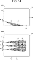
- the food sensor 31 may be as illustrated in FIG. 14 .
- FIG. 14 is a diagram illustrating an exemplary arrangement and a detection region of a food sensor in a cooking appliance according to a modification of the present invention.
- a food sensor 31 in FIG. 14 is constituted of a reflection type photosensor, for instance, and detects the presence or absence of a detection target (food) by causing light from a light emitting element in the reflection type photosensor to hit the detection target and receiving light reflected on the detection target.
- a range of irradiation with the light from the light emitting element in the food sensor 31 specifies a sensor detection area 32.
- the food sensor 31 receives a reflected light from the sensor detection area 32 and transmits a signal (light reception signal) indicating the reception of light to the controller 22 ( FIG. 10 ) of the cooking appliance 1.
- the controller 22 determines whether a food 40 is present in the heating chamber 13 from the light reception signal as transmitted.
- three food sensors 31 are arranged in a depth direction of the heating chamber 13, as an example illustrated in a part with a reference sign 1402 of FIG. 14 .
- the three food sensors 31 are at the same height from a placement face.
- the three food sensors 31 at the same height from the placement face are used to form the sensor detection area 32, which is a region for detecting the presence or absence of the food 40 to be placed on the flat plate 13c of the heating chamber 13.
- the food sensors 31 are not particularly limited in number, height of installation, and the like as long as the sensor detection area 32 with a desired size is formed.
- Appatus Functions of the cooking appliance 1 (hereinafter referred to as "apparatus") can be implemented by a program for causing a computer to control the apparatus, that is to say, to serve as the respective control blocks (respective units included in the controller 22, in particular) of the apparatus.
- the apparatus includes a computer having at least one control device (processor, for instance) and at least one storage (memory, for instance) as hardware for executing the program.
- control device processor, for instance
- storage memory, for instance
- the program may be recorded on one or more non-transitory computer-readable recording media. Such recording media may or may not be included in the apparatus. In the latter case, the program may be fed to the apparatus through an optional wired or wireless transmission medium.
- control blocks It is also possible to implement part or the whole of functions of the respective control blocks by logic circuits. For instance, an integrated circuit with logic circuits so formed as to serve as the respective control blocks is placed in the category of the present invention.
- functions of the respective control blocks can be implemented by a quantum computer, for instance.
- AI artificial intelligence
- the AI system may work on the control device or other device (edge computer, cloud server or the like).
- a cooking appliance includes the heating chamber 13, a door (the front door 12) provided on the heating chamber 13, an opening and closing detector (the front door opening and closing detector 25) that detects opening and closing of the door (front door 12), the determination unit 22a, which determines whether a food is present in the heating chamber 13, the reader 16, which reads an information code for cooking the food, and the heating control unit 22b, which performs heating control on the food in the heating chamber 13 based on the information code read by the reader 16.
- the heating control unit 22b starts the heating of the food if it is detected by the opening and closing detector (front door opening and closing detector 25) that the door (front door 12) is closed and it is determined by the determination unit 22a that the food is present in the heating chamber 13.
- the heating control unit performs the heating control on a food if the food is present in the heating chamber when the door of the heating chamber is closed.
- the heating of a food is to be automatically started if it is determined that a food is present in the state, where the door of the heating chamber is closed.
- the time and effort taken up to the start of cooking of a food are reduced even if the exterior light affects the detection of the food.
- a cooking appliance according to a second aspect of the present invention is provided by modifying the cooking appliance of the first aspect so that the determination unit 22a may determine whether a food is present in the heating chamber 13 if it is detected by the opening and closing detector (front door opening and closing detector 25) that the door (front door 12) is closed, and so that the heating control unit 22b may start the heating of a food if it is determined by the determination unit 22a that the food is present in the heating chamber 13.
- a cooking appliance according to a third aspect of the present invention is provided by modifying the cooking appliance of the second aspect so that the determination unit 22a may determine whether a food is present in the heating chamber 13 if it is detected by the opening and closing detector (front door opening and closing detector 25) that the door (front door 12) is opened, and so that the heating control unit 22b may start the heating of a food if it is detected by the opening and closing detector (front door opening and closing detector 25) that the door (front door 12) is closed and it is determined by the determination unit 22a that the food is present in the heating chamber 13 in the state, where it has been detected by the opening and closing detector (front door opening and closing detector 25) that the door (front door 12) is opened and it has been determined by the determination unit 22a that no foods are present in the heating chamber 13.
- heating in a state where no foods are present in the heating chamber, namely, no-load operation is suppressed so as to perform the heating control when a food is certainly present.
- a cooking appliance according to a fourth aspect of the present invention is provided by modifying the cooking appliance of the second aspect so that the determination unit 22a may determine whether a food is present in the heating chamber 13 if it is detected by the opening and closing detector (front door opening and closing detector 25) that the door (front door 12) is opened, and so that the heating control unit 22b may start the heating of a food if it is detected by the opening and closing detector (front door opening and closing detector 25) that the door (front door 12) is closed in the state, where it has been detected by the opening and closing detector (front door opening and closing detector 25) that the door (front door 12) is opened and it has been determined by the determination unit 22a that the food is present in the heating chamber 13.
- a cooking appliance according to a fifth aspect of the present invention is provided by modifying the cooking appliance of any one of the first through fourth aspects so that the cooking appliance may include the food sensor 31 for detecting a food in the heating chamber 13, which sensor includes a light emitter (light emitting element 31a) that emits light and a light receiver (the first and second light receiving elements 31b and 31c) that receives light emitted from the light emitter (light emitting element 31a), and so that the determination unit 22a may determine whether a food is present in the heating chamber 13 according to the amount of light received by the light receiver (first and second light receiving elements 31b and 31c).
- the light receiver is not affected by the exterior light and it is determined with high accuracy whether a food is present.
- a heating control method for a cooking appliance is a heating control method for a cooking appliance including: the heating chamber 13; a door (the front door 12) provided on the heating chamber 13; an opening and closing detector (the front door opening and closing detector 25) that detects opening and closing of the door (front door 12); the determination unit 22a, which determines whether a food is present in the heating chamber 13; the reader 16, which reads an information code for cooking the food; and the heating control unit 22b, which performs heating control on the food in the heating chamber 13 based on the information code read by the reader 16.
- the heating control method includes starting the heating of the food with the heating control unit 22b if the opening and closing detector (front door opening and closing detector 25) detects that the door (front door 12) is closed and the determination unit 22a determines that the food is present in the heating chamber 13.
- the heating control unit performs the heating control on a food if the food is present in the heating chamber when the door of the heating chamber is closed. Consequently, the heating control is performed on a food when the food is certainly present in the heating chamber.
- the present invention is not limited to the above embodiments but can variously be modified within the range of recital in the claims.
- An embodiment obtained by appropriately combining technical means disclosed in different embodiments with one another falls within a technical scope of the present invention. It is further possible to combine technical means disclosed in the respective embodiments with one another so as to form a new technical feature.
Landscapes
- Engineering & Computer Science (AREA)
- Chemical & Material Sciences (AREA)
- Combustion & Propulsion (AREA)
- Mechanical Engineering (AREA)
- General Engineering & Computer Science (AREA)
- Electric Ovens (AREA)
- Electric Stoves And Ranges (AREA)
- Cookers (AREA)
Abstract
Description
- The present invention relates to a cooking appliance that heats a food placed inside a heating chamber, and a heating control method.
- A cooking appliance disclosed in
Patent Document 1 includes a detection sensor (a floodlighting element and a light receiving element) for detecting a food in a cooking chamber. The floodlighting element and the light receiving element are provided on left and right side walls as viewed from the opening side of the cooking chamber, which is opened and closed with a door, respectively. In other words, in the cooking appliance disclosed inPatent Document 1, light is emitted from the floodlighting element provided on one side wall toward the light receiving element oppositely provided on the other side wall, so as to detect the presence or absence of a food in or from the cooking chamber based on the amount of light received by the light receiving element. - On the other hand, among recent cooking appliances such as microwave ovens, there exists a cooking appliance that reads, with a reader, a barcode put on a container of a food to be heated and indicating the kind of the food, so as to heat the food in accordance with the heating information (heating temperature and heating time) corresponding to the kind of the food (see Patent Document 2, for instance). In such cooking appliance, cooking is to be automatically performed if the food is placed in the cooking chamber and the cooking chamber's door is closed.
-
- Patent Document 1:
JP H05-340546 A - Patent Document 2:
JP 2006-064362 A - When the heating information on the food is read and the door of the cooking chamber is closed so as to automatically perform cooking, it is required to check, in a state where the door is opened, whether the food is placed in the cooking chamber. It is therefore conceivable to use such floodlighting element and light receiving element arranged on left and right side walls in the cooking chamber, respectively, as disclosed in
Patent Document 1 to determine whether the food is placed in the cooking chamber in the state, where the door is opened. - In the state, where the door of the cooking chamber is opened, however, an exterior light (sunlight, for instance) may enter the light receiving element arranged on the side wall and increase the amount of light received by the light receiving element, so that it is feared that, although present in the cooking chamber, the food is not determined to be present, and cooking is not automatically started when the door is closed. If a mistaken detection of the food occurs under the influence of the exterior light or the like, it is highly possible that cooking is not automatically started even when the door is closed again after being opened to make sure of the food in the cooking chamber, so that cooking needs to be manually started.
- Consequently, a problem arises in that it requires time and effort before the start of cooking of the food if the exterior light affects the detection of the food in the cooking chamber.
- An aspect of the present invention is aimed at achieving a cooking appliance allowing the time and effort taken up to the start of cooking of the food to be reduced even if the exterior light affects the detection of the food.
- In order to solve the problem as above, a cooking appliance according to an aspect of the present invention includes a heating chamber, a door provided on the heating chamber, an opening and closing detector that detects opening and closing of the door, a determiner that determines whether a food is present in the heating chamber, a reader that reads an information code for cooking the food, and a heating controller that performs heating control on the food in the heating chamber based on the information code read by the reader.
- The heating controller starts the heating of the food if the opening and closing detector detects that the door is closed and the determiner determines that the food is present in the heating chamber.
- A heating control method for a cooking appliance according to an aspect of the present invention is a heating control method for a cooking appliance including: a heating chamber; a door provided on the heating chamber; an opening and closing detector that detects opening and closing of the door; a determiner that determines whether a food is present in the heating chamber; a reader that reads an information code for cooking the food; and a heating controller that performs heating control on the food in the heating chamber based on the information code read by the reader. The heating control method includes starting the heating of the food with the heating controller if the opening and closing detector detects that the door is closed and the determiner determines that the food is present in the heating chamber.
- According to an aspect of the present invention, the time and effort taken up to the start of cooking of a food are reduced even if the exterior light affects the detection of the food.
-
-
FIG. 1 is a perspective view of a cooking appliance according to an embodiment of the present invention with a front door closed, as obliquely viewed from an upper front. -
FIG. 2 is a front view of the cooking appliance illustrated inFIG. 1 , with the front door being opened. -
FIG. 3 is a perspective view of the cooking appliance illustrated inFIG. 1 , with the front door being opened, as obliquely viewed from a lower right. -
FIG. 4 is a vertical cross-sectional view of a control frame, illustrating a state of installation of a reader included in the cooking appliance illustrated inFIG. 1 . -
FIG. 5 is a diagram illustrating a reading region of the reader illustrated inFIG. 4 . -
FIG. 6 is a diagram illustrating specific examples of an information code. -
FIG. 7 is a diagram illustrating an exemplary arrangement and a detection region of a food sensor in the cooking appliance illustrated inFIG. 1 . -
FIG. 8 is a circuit diagram illustrating an equivalent circuit of the food sensor illustrated inFIG. 7 . -
FIG. 9 is a diagram for explaining a method for determining whether a food is present with the food sensor illustrated inFIG. 8 . -
FIG. 10 is a functional block diagram of a control device included in the cooking appliance illustrated inFIG. 1 . -
FIG. 11 is a flowchart illustrating a flow of processing up to start of cooking in the cooking appliance illustrated inFIG. 1 . -
FIG. 12 is a flowchart illustrating a flow of processing up to the start of cooking in a cooking appliance according to a second embodiment of the present invention. -
FIG. 13 is a flowchart illustrating a flow of processing up to the start of cooking in a cooking appliance according to a third embodiment of the present invention. -
FIG. 14 is a diagram illustrating an exemplary arrangement and a detection region of a food sensor in a cooking appliance according to a modification of the present invention. - In the following, an embodiment of the present invention is described in detail.
FIG. 1 is a perspective view of acooking appliance 1 of the present embodiment, with afront door 12 that is openable and is provided on a body of thecooking appliance 1 being closed, as obliquely viewed from an upper front.FIG. 2 is a front view of thecooking appliance 1 illustrated inFIG. 1 , with thefront door 12 being opened.FIG. 3 is a perspective view of thecooking appliance 1 illustrated inFIG. 1 , with thefront door 12 being opened, as obliquely viewed from a lower right. - As illustrated in
FIGS. 1 through 3 , thecooking appliance 1 is a microwave oven, for instance, and is provided with anoperation panel 11 in an upper front portion and thefront door 12 below theoperation panel 11. Thefront door 12 is a door for opening and closing aheating chamber 13 provided in rear of thefront door 12 and is closed so as to cover a front opening 13b of theheating chamber 13. In the present embodiment, thefront door 12 is a laterally openable door that revolves about an edge on a user's left, and is provided with ahandle 14 in the vicinity of a right edge opposite to the edge as the center of revolution. - As illustrated in
FIG. 2 , afood sensor 31 is provided on aside wall 13a in theheating chamber 13. It is detected by thefood sensor 31 that a food is or is not placed on aflat plate 13c provided on a bottom face in theheating chamber 13. In other words, thefood sensor 31 detects presence or absence of a food in or from theheating chamber 13. Thefood sensor 31 is constituted of alight emitting element 31a arranged on theside wall 13a on the right as viewed from the front opening 13b as well as a firstlight receiving element 31b and a secondlight receiving element 31c both arranged on theside wall 13a on the left. Thefood sensor 31 is thus a so-called transmission type photosensor, and receives the light, which is emitted from thelight emitting element 31a, with the firstlight receiving element 31b and the secondlight receiving element 31c arranged on an opposite face. Thefood sensor 31 will be detailed later. - The
operation panel 11 is provided on a front face of acontrol frame 15. Theoperation panel 11 is provided so that a front face of theoperation panel 11 may substantially be flush with a front face of thefront door 12 in a front and rear direction of thecooking appliance 1. - In the interior of the
control frame 15, a control board (not illustrated) exerting such functions as control of adisplay 30 of theoperation panel 11 and acceptance of user operation to an input key and the like is provided. -
FIG. 4 is a vertical cross-sectional view of thecontrol frame 15, illustrating a state of installation of areader 16.FIG. 5 is a diagram illustrating areading region 19 of thereader 16. - As illustrated in
FIG. 4 , thecontrol frame 15 is so provided as to protrude in front of thecooking appliance 1. Thereader 16 is mounted on the underside of a reader board (circuit board) 17 and provided as such in a lower portion of the interior of thecontrol frame 15. Thereader board 17 includes a drive circuit for thereader 16. Thus, thereader 16 is so provided as to be installed in a position above the front opening 13b of theheating chamber 13 outside theheating chamber 13 and to have thereading region 19 below the position of installation. - The
reader 16 is a barcode reader, for instance, and is to read an information code (barcode, for instance) imparted to a food to be heated in thecooking appliance 1 or a container of the food. - The reading
region 19 of thereader 16 is a region below thereader 16 as illustrated inFIG. 5 , and thecontrol frame 15 is provided with atransparent reading window 18 in a bottom portion opposite to thereader 16. - The reading
region 19 of thereader 16 is shown by a red light, for instance, so that a user may visually recognize thereading region 19. The red light is emitted by a reading region illuminator 21 (seeFIG. 10 ). Used as thereading region illuminator 21 is a red light emitting diode (red LED), for instance. The light showing the readingregion 19 is not limited to the red light but may be other light visible to the user, such as a laser light. The number of red LEDs may be one or more. - The
reader 16 is provided in a central portion in a width direction (lateral direction) of thefront opening 13b of theheating chamber 13, as seen fromFIGS. 2 and3 . -
FIG. 6 is a diagram illustrating examples of the information code, that is to say, illustrating an exemplary information code constituted of a two-dimensional code (Quick Response (QR) Code (registered trademark)) with areference sign 1061, and an exemplary information code constituted of a one-dimensional barcode with areference sign 1062. - The information code is used for cooking a food. For instance, the information code includes information indicating the kind of a food and information (heating information) indicating conditions for cooking the food, whose kind is indicated. The heating information is information required for cooking, and contains the heating time and the wattage of high frequency power in the
cooking appliance 1. Specifically, the information code includes the information indicating the kind of a food, that is to say, indicating whether the food is a boxed meal or a rice ball (or further indicating the kind of the boxed meal or the rice ball), for instance, and the heating information containing the heating time and wattage of high frequency power corresponding to the food, whose kind is indicated. The information code is imparted to a food or a container of the food by printing or with a sticker, for instance. Since the information code is used for cooking a specified food, the information code may only include information specifying a food and the heating information on the specified food may be acquired from an external server, or a server 51 (FIG. 10 ). The information code may only include the heating information on a food. - The information code may be a two-dimensional code such as illustrated in
FIG. 6 with thereference sign 1061 or a one-dimensional barcode such as illustrated inFIG. 6 with thereference sign 1062. The information code is not particularly limited to the barcode or the like as long as the information code is capable of indicating the kind of a food. -
FIG. 7 is a diagram illustrating an exemplary arrangement of thelight emitting element 31a, the firstlight receiving element 31b, and the secondlight receiving element 31c constituting thefood sensor 31 in thecooking appliance 1 illustrated inFIG. 1 , and a sensor detection area 32 (afirst detection area 32a and asecond detection area 32b) of thefood sensor 31.FIG. 7 has a part with areference sign 1071 illustrating theheating chamber 13 as viewed from the top face side, and a part with areference sign 1072 illustrating theheating chamber 13 as viewed from thefront opening 13b side. -
FIG. 8 is a circuit diagram illustrating an equivalent circuit of thefood sensor 31.FIG. 9 is a diagram for explaining a method for determining whether a food is present with thefood sensor 31. - The
light emitting element 31a is constituted of a near infrared LED, and the firstlight receiving element 31b and the secondlight receiving element 31c are each constituted of a phototransistor (receiving light at a wavelength of 900 nm). In other words, the first and secondlight receiving elements light emitting element 31a. The equivalent circuit of thefood sensor 31 is as illustrated inFIG. 8 . - The
light emitting element 31a is provided in a nearly central position on theside wall 13a on the right in theheating chamber 13 as illustrated in the part with thereference sign 1071 ofFIG. 7 , which position is at a height H1 (of 15 mm in the illustrated example) from theflat plate 13c on the bottom face of theheating chamber 13 as illustrated in the part with thereference sign 1072 ofFIG. 7 . The firstlight receiving element 31b and the secondlight receiving element 31c are provided in the positions, which are separated from a straight line extending from thelight emitting element 31a to theside wall 13a on the opposite side at specified distances, respectively, as illustrated in the part with thereference sign 1071 ofFIG. 7 and are each at a specified height H2 from theflat plate 13c on the bottom face of theheating chamber 13 as illustrated in the part with thereference sign 1072 ofFIG. 7 . The height H2, at which the first and secondlight receiving elements light emitting element 31a is provided. - A specified region including a light emission region extending from the
light emitting element 31a emitting the near infrared light to the firstlight receiving element 31b receiving the emitted near infrared light is assumed as thefirst detection area 32a for food detection, and a specified region including a light emission region extending from thelight emitting element 31a emitting the near infrared light to the secondlight receiving element 31c receiving the emitted near infrared light is assumed as thesecond detection area 32b for food detection. The first andsecond detection areas sensor detection area 32 on theflat plate 13c of theheating chamber 13. Thus, thefood sensor 31 is able to detect that a food is or is not placed in thesensor detection area 32. - The
food sensor 31 transmits light reception signals indicating the reception of light by the firstlight receiving element 31b and the secondlight receiving element 31c to a controller 22 (FIG. 10 ) of thecooking appliance 1. Thecontroller 22 determines whether a food is present in theheating chamber 13 from the light reception signals as transmitted. - Specifically, the
controller 22 determines that a food is present if either of an output voltage (Vout 1) of the firstlight receiving element 31b and an output voltage (Vout 2) of the secondlight receiving element 31c is lower than a first threshold voltage (Vth 1 = 0.6 V), and determines that no foods are present if either of the output voltage (Vout 1) and the output voltage (Vout 2) is equal to or higher than the first threshold voltage (Vth 1 = 0.6 V), as illustrated inFIG. 9 . The output voltage (Vout 1) of the firstlight receiving element 31b and the output voltage (Vout 2) of the secondlight receiving element 31c are each higher than 4.0 V in a state where no foods are certainly present on theflat plate 13c of theheating chamber 13. Therefore, a voltage of 4.0 V is set as a second threshold voltage (Vth 2) and thecontroller 22 determines that no foods are present if either of the output voltage (Vout 1) of the firstlight receiving element 31b and the output voltage (Vout 2) of the secondlight receiving element 31c is higher than the second threshold voltage (Vth 2 = 4.0 V). In other words, the output voltage of a light receiving element is lower than 0.6 V if a food is present in thesensor detection area 32 on theflat plate 13c of theheating chamber 13, and the output voltage of a light receiving element is higher than 4.0 V if no foods are present in thesensor detection area 32. The values of the first threshold voltage (Vth 1) and the second threshold voltage (Vth 2) are not limited to 0.6 V and 4.0 V, respectively, but changed appropriately to the specifications of thelight emitting element 31a as well as the first and secondlight receiving elements - Even if a food is placed on the
flat plate 13c of theheating chamber 13, the output voltage of a light receiving element may be equal to or higher than 0.6 V but not higher than 4.0 V if the food is not appropriately placed in the sensor detection area 32 (if the food only occupies part of the sensor detection area 32), if the food (or the container thereof) is of a high transparency, if the food is placed indeed in thesensor detection area 32 but under the influence of an exterior light, and so forth. In other words, it is difficult to determine whether a food is certainly placed in theheating chamber 13, if the output voltage of a light receiving element is equal to or higher than 0.6 V but not higher than 4.0 V. Therefore, thecontroller 22 determines that no foods are present if either of the output voltage (Vout 1) of the firstlight receiving element 31b and the output voltage (Vout 2) of the secondlight receiving element 31c is equal to or higher than 0.6 V but not higher than 4.0 V. As a result, heating is only performed if a food is certainly present in theheating chamber 13, leading to the suppression of no-load operation. The determinations as above are implemented by adetermination unit 22a of thecontroller 22 to be described later. Thedetermination unit 22a will be detailed later. -
FIG. 10 is a functional block diagram of a control device included in thecooking appliance 1. The control device includes thecontroller 22, which controls operations of thecooking appliance 1. Thecontroller 22 is constituted of a microcomputer, for instance, and has a central processing unit (CPU), a read-only memory (ROM), and a random access memory (RAM). - As illustrated in
FIG. 10 , thecontroller 22 is connected with theoperation panel 11, aheating operation section 23, thereader 16, thereading region illuminator 21, areading result notifier 24, thefood sensor 31, a front door opening and closing detector (opening and closing detector) 25, and a memory (storage) 52. The front door opening andclosing detector 25 is constituted of, for instance, a switch that turns on when thefront door 12 is closed, and detects an opened state and a closed state of thefront door 12. The result of detection by the front door opening andclosing detector 25 is sent to thecontroller 22. - The
heating operation section 23 is an operation section for heating a food placed in theheating chamber 13, such as a microwave output device or a heater. Thereading result notifier 24 is a buzzer or a sound generator, and is controlled by thecontroller 22 so as to notify the user of the success or failure in reading of the information code by thereader 16. - The
controller 22 controls theheating operation section 23 so that the food may be heated in accordance with the heating information as acquired through the reading of the information code by thereader 16. A variety of heating information corresponding to various kinds of foods may previously be registered in theserver 51, and thecontroller 22 may acquire, from theserver 51, heating information corresponding to the kind of a food acquired through the reading of the information code by thereader 16. Thecooking appliance 1 in itself may have the heating information corresponding to the kind of a food. In that case, thecooking appliance 1 does not need to communicate with theserver 51. - The
controller 22 includes thedetermination unit 22a, which determines whether a food is present in theheating chamber 13 based on a detection result sent from thefood sensor 31, aheating control unit 22b for controlling a heating operation of theheating operation section 23 based on a determination result of thedetermination unit 22a, and areading control unit 22c for controlling a reading operation of thereader 16 based on the determination result of thedetermination unit 22a. - The
food sensor 31 is a sensor for detecting a food in theheating chamber 13, and includes thelight emitting element 31a (light emitter), which emits light, and the first and secondlight receiving elements light emitting element 31a. - The
determination unit 22a determines whether a food is present in theheating chamber 13, according to the output voltage of the firstlight receiving element 31b and the secondlight receiving element 31c (namely, the amount of light received by the firstlight receiving element 31b and the secondlight receiving element 31c) of thefood sensor 31. Specifically, thedetermination unit 22a determines whether a food is present in theheating chamber 13 based on a signal indicating the detection result sent from the food sensor 31 (the output voltage of the firstlight receiving element 31b and the secondlight receiving element 31c). A specific method for determining whether a food is present is as follows: If a food is placed in thesensor detection area 32, the light emitted by thelight emitting element 31a of thefood sensor 31 decreases before being received by the firstlight receiving element 31b and the secondlight receiving element 31c. Consequently, the output voltage of the firstlight receiving element 31b and the secondlight receiving element 31c is reduced. If such output voltage has a value lower than a preset value (Vth 1 inFIG. 9 ), it is determined that a food is present. If no foods are placed in thesensor detection area 32, the light emitted by thelight emitting element 31a of thefood sensor 31 decreases indeed before being received by the firstlight receiving element 31b and the secondlight receiving element 31c but with a small degree of decrease. Consequently, the output voltage of the firstlight receiving element 31b and the secondlight receiving element 31c is not lower than that when it is determined that a food is present. If such output voltage has a value equal to or higher than a preset value (Vth 1 or Vth 2 inFIG. 9 ), it is determined that no foods are present. - The
heating control unit 22b permits the heating operation of theheating operation section 23 if the detection result of the front door opening andclosing detector 25 as sent to thecontroller 22 is that thefront door 12 is closed and the determination result of thedetermination unit 22a is that a food is present in theheating chamber 13, and does not permit the heating operation of theheating operation section 23 if the determination result is that no foods are present in theheating chamber 13. - The operations of the
cooking appliance 1 are described below. In this regard, a food is assumed as a packed lunch with an information code imparted to an upper face of its container, and description is made on the case, where the packed lunch is heated with thecooking appliance 1. - Initially, the user recognizes a guidance indication 20 ("open the door and expose the information code to the red light", for instance) on the
operation panel 11. Then, the user opens thefront door 12 in accordance with theguidance indication 20. If the front door opening andclosing detector 25 detects the opened state of thefront door 12, thecontroller 22 causes thereader 16 and the reading region illuminator 21 to operate. - Next, the user moves the packed lunch so that the information code may be in the
reading region 19 of the reader 16 (the red light may hit the information code), in accordance with theguidance indication 20 on theoperation panel 11. - As a result of such operation, the
reader 16 reads the information code imparted to the packed lunch. If thereader 16 successfully reads the information code, thecontroller 22 causes thereading result notifier 24 to notify the user of the reading result. At this time, thereading result notifier 24 operates to generate either or both of a continuous beeping sound and a voice saying "reading of the information code succeeded". - If notified by the
reading result notifier 24 of the success of reading of the information code, the user places the packed lunch in theheating chamber 13 and then closes thefront door 12. In such situation, thedetermination unit 22a determines whether the packed lunch to be heated is placed in a specified position in theheating chamber 13. If it is determined by thedetermination unit 22a that the packed lunch is present in theheating chamber 13, the determination result is sent to theheating control unit 22b. On the other hand, the front door opening andclosing detector 25 sends, to theheating control unit 22b, a detection signal indicating that thefront door 12 is closed. As a result, heating control by theheating control unit 22b, namely, the heating operation of theheating operation section 23 is permitted and heating of the packed lunch is started. - If the packed lunch has been warmed up by following the procedure as described above, the user is notified of the completion of heating of the packed lunch and takes the packed lunch out of the
heating chamber 13. If the packed lunch is taken out of theheating chamber 13 and, accordingly, lost from thesensor detection area 32 in theheating chamber 13, a signal received by thefood sensor 31 has a reference value, so that thedetermination unit 22a of thecontroller 22 determines that the packed lunch is not present in theheating chamber 13. Based on this determination result (that the packed lunch is not placed in the heating chamber 13) of thedetermination unit 22a, theheating control unit 22b does not permit the heating operation of theheating operation section 23. Consequently, theheating operation section 23 does not perform the heating operation in the state, where the packed lunch is not placed in theheating chamber 13. In other words, the heating operation is not performed in a no-load state. -
FIG. 11 is a flowchart illustrating a flow of processing up to the start of cooking in the cooking appliance 1 (heating control method). - Initially, front door opening and closing detection is performed (step S11). In step S11, the opening or closing of the
front door 12 is detected by the front door opening andclosing detector 25 and the detection result is sent to thedetermination unit 22a and theheating control unit 22b. - Next, the
determination unit 22a determines whether thefront door 12 is closed (step S12). In step S12, thedetermination unit 22a determines whether thefront door 12 is closed from the detection result of the front door opening andclosing detector 25. If it is determined by thedetermination unit 22a that thefront door 12 is closed (YES in step S12), the processing proceeds to step S13 so as to perform the food detection. The method for detecting a food is described above with reference toFIGS. 8 and 9 , so that no description is made on such method here. - In step S13, the food detection is performed by the
food sensor 31 and the detection result is sent to thedetermination unit 22a. - Subsequently, the
determination unit 22a determines whether a food is present (step S14). In step S14, thedetermination unit 22a determines whether a food is present from the detection result sent from thefood sensor 31. The detection result of thefood sensor 31 is represented as a value of the output voltage of the firstlight receiving element 31b and the secondlight receiving element 31c. Thedetermination unit 22a determines whether a food is present in theheating chamber 13 from the value of the output voltage and sends the determination result that a food is present (YES in step S14) to theheating control unit 22b so as to start the heating (step S15). In step S15, theheating control unit 22b allows the control of theheating operation section 23 if the detection result sent from the front door opening andclosing detector 25 is that thefront door 12 is closed and the determination result sent from thedetermination unit 22a is that a food is present. - If it is determined that no foods are present (NO in step S14), the
determination unit 22a sends the determination result to theheating control unit 22b and theheating control unit 22b does not allow the control of theheating operation section 23. As a result, the processing ends because a food as a heating control target is not present. - In other words, the
heating control unit 22b does not allow the control of theheating operation section 23 solely with the detection result that thefront door 12 is closed, but allows the control of theheating operation section 23 with both of the detection result that thefront door 12 is closed and the determination result that a food is present. - In the
cooking appliance 1 having the configuration as above, it is determined whether a food is placed in theheating chamber 13, even if thefront door 12 is closed, and the heating control is performed if the result of such determination is that a food is placed in theheating chamber 13. Thus, even if it is determined before thefront door 12 is closed whether a food is present in theheating chamber 13 and, although it should actually be determined that a food is present, it is determined under the influence of the exterior light that no foods are present, such malfunction that the heating control is not started while a food is present is prevented because it is determined again after thefront door 12 is closed whether a food is present. - If the information code is read so as to acquire the heating information on a food in advance and the heating control is performed on the food immediately after the
front door 12 is closed, as in theabove cooking appliance 1, in particular, it is possible to unfailingly perform the heating control when a food is present, by determining after thefront door 12 is closed whether a food is present. - Consequently, even if it is determined that no foods are present due to a mistaken detection made under the influence of the exterior light when the door of the heating chamber is opened, the heating of a food is to be automatically started if it is determined that a food is present in the state, where the door of the heating chamber is closed. As a result, the time and effort taken up to the start of cooking of a food are reduced even if the exterior light affects the detection of the food.
- In the present embodiment, the example, in which the presence or absence of a food is detected after the
front door 12 is closed, is described. In second and third embodiments below, the example, in which a process for detecting the presence or absence of a food is performed initially when thefront door 12 is opened, is described. - Another embodiment of the present invention is described below. For convenience of description, components identical in function to the components described in the above embodiment are given the same reference signs and not described anew.
- In the present embodiment, a
cooking appliance 1 is the same as thecooking appliance 1 of the first embodiment but processing up to the start of the heating control is different from that in the first embodiment. In other words, control by thecontroller 22 is different from that in the first embodiment. -
FIG. 12 is a flowchart illustrating a flow of processing up to the start of cooking in the present embodiment. - Initially, front door opening and closing detection is performed (step S21). In step S21, the opening or closing of the
front door 12 is detected by the front door opening andclosing detector 25 and the detection result is sent to thedetermination unit 22a and theheating control unit 22b. - Next, the
determination unit 22a determines whether thefront door 12 is opened (step S22). In step S22, thedetermination unit 22a determines whether thefront door 12 is opened from the detection result of the front door opening andclosing detector 25. If it is determined by thedetermination unit 22a that thefront door 12 is opened (YES in step S22), the processing proceeds to step S23 so as to perform the food detection. The method for detecting a food is described above with reference toFIGS. 8 and 9 , so that no description is made on such method here. - In step S23, the food detection is performed by the
food sensor 31 and the detection result is sent to thedetermination unit 22a. - Subsequently, the
determination unit 22a determines whether any food is absent (step S24). In step S24, the result of detection by thefood sensor 31 is sent to thedetermination unit 22a and thedetermination unit 22a determines whether a food is present. If thedetermination unit 22a determines that any food is absent (YES in step S24), the front door opening andclosing detector 25 performs the front door opening and closing detection (step S25). In step S25, the opening or closing of thefront door 12 is detected by the front door opening andclosing detector 25 and the detection result is sent to thedetermination unit 22a and theheating control unit 22b. If thedetermination unit 22a determines that a food is present (NO in step S24), the processing returns to step S23 so as to perform the food detection. - Next, the
determination unit 22a determines whether thefront door 12 is closed (step S26). In step S26, thedetermination unit 22a determines whether thefront door 12 is closed from the detection result of the front door opening andclosing detector 25. If it is determined by thedetermination unit 22a that thefront door 12 is closed (YES in step S26), the processing proceeds to step S27 so as to perform the food detection. If it is determined by thedetermination unit 22a that thefront door 12 is opened (NO in step S26), the processing returns to step S25 so as to perform the front door opening and closing detection. - In step S27, the food detection is performed by the
food sensor 31 and the detection result is sent to thedetermination unit 22a. - Subsequently, the
determination unit 22a determines whether a food is present (step S28). In step S28, thedetermination unit 22a determines whether a food is present based on the detection result sent from thefood sensor 31. Thedetermination unit 22a sends the determination result that a food is present (YES in step S28) to theheating control unit 22b. Theheating control unit 22b starts the heating based on the determination result from thedetermination unit 22a that a food is present (step S29). In step S29, theheating control unit 22b allows the control of theheating operation section 23 if the detection result sent from the front door opening andclosing detector 25 is that thefront door 12 is closed and the determination result sent from thedetermination unit 22a is that a food is present. - In the
cooking appliance 1 having the configuration as above, theheating control unit 22b starts the heating of a food if it is detected by the front door opening andclosing detector 25 that thefront door 12 is closed and it is determined by thedetermination unit 22a that the food is present in theheating chamber 13 in the state, where it has been detected by the front door opening andclosing detector 25 that thefront door 12 is opened and it has been determined by thedetermination unit 22a that no foods are present in theheating chamber 13. Thus, it is determined whether a food is present when thefront door 12 is opened, and opening and closing detection is performed by the front door opening andclosing detector 25 on thefront door 12 if it is determined that a food is present, so that it is possible to automatically start the heating of a food when the food is certainly present in the heating chamber. - The following description is made on yet another embodiment of the present invention. For convenience of description, components identical in function to the components described in the above embodiments are given the same reference signs and not described anew.
- In the present embodiment, a
cooking appliance 1 is the same as thecooking appliance 1 of the first embodiment but processing up to the start of the heating control is different from that in the first embodiment. In other words, control by thecontroller 22 is different from that in the first embodiment. -
FIG. 13 is a flowchart illustrating a flow of processing up to the start of cooking in the present embodiment. - Initially, front door opening and closing detection is performed (step S31). In step S31, the opening or closing of the
front door 12 is detected by the front door opening andclosing detector 25 and the detection result is sent to thedetermination unit 22a and theheating control unit 22b. - Next, the
determination unit 22a determines whether thefront door 12 is opened (step S32). In step S32, thedetermination unit 22a determines whether thefront door 12 is opened from the detection result of the front door opening andclosing detector 25. If it is determined by thedetermination unit 22a that thefront door 12 is opened (YES in step S32), the processing proceeds to step S33 so as to perform the food detection. - In step S33, the food detection is performed by the
food sensor 31 and the detection result is sent to thedetermination unit 22a. - Subsequently, the
determination unit 22a determines whether a food is present (step S34). In step S34, thedetermination unit 22a determines whether a food is present based on the detection result sent from thefood sensor 31. If thedetermination unit 22a determines that a food is present (YES in step S34), the front door opening and closing detection is performed by the front door opening and closing detector 25 (step S35). In step S35, the result of detection by the front door opening andclosing detector 25 is sent to thedetermination unit 22a and theheating control unit 22b. If thedetermination unit 22a determines that no foods are present (NO in step S34), the processing returns to step S33 and the food detection is performed by thefood sensor 31. - Next, the
determination unit 22a determines whether thefront door 12 is closed (step S36). In step S36, thedetermination unit 22a determines whether thefront door 12 is closed from the detection result of the front door opening andclosing detector 25. If it is determined by thedetermination unit 22a that thefront door 12 is closed (YES in step S36), the processing proceeds to step S37 so as to start the heating. In step S37, theheating control unit 22b allows the control of theheating operation section 23 if the detection result sent from the front door opening andclosing detector 25 is that thefront door 12 is closed and the determination result sent from thedetermination unit 22a is that a food is present. - If it is determined by the
determination unit 22a that thefront door 12 is opened (NO in step S36), the processing returns to step S35 so as to perform the front door opening and closing detection. - If it is determined by the
determination unit 22a that thefront door 12 is closed (NO) in step S32, the processing proceeds to step S38 so as to perform the food detection. - In step S38, the food detection is performed by the
food sensor 31 and the detection result is sent to thedetermination unit 22a. - Subsequently, the
determination unit 22a determines whether a food is present (step S39). In step S39, thedetermination unit 22a determines whether a food is present based on the detection result sent from thefood sensor 31. If thedetermination unit 22a determines that a food is present (YES in step S39), the processing proceeds to step S37. In step S37, the heating is started. In this step, theheating control unit 22b allows the control of theheating operation section 23 if the detection result sent from the front door opening andclosing detector 25 is that thefront door 12 is closed and the determination result sent from thedetermination unit 22a is that a food is present. - In step S39, the
determination unit 22a sends the determination result that no foods are present (NO) to theheating control unit 22b, so that theheating control unit 22b does not allow the control of theheating operation section 23. In other words, the processing ends because a food as a heating control target is not present. - In the
cooking appliance 1 having the configuration as above, theheating control unit 22b starts the heating of a food if it is detected by the front door opening andclosing detector 25 that thefront door 12 is closed in the state, where it has been detected by the front door opening andclosing detector 25 that thefront door 12 is opened and it has been determined by thedetermination unit 22a that the food is present in theheating chamber 13. Thus, it is determined whether a food is present when thefront door 12 is opened, and opening and closing detection is performed by the front door opening andclosing detector 25 on thefront door 12 if it is determined that a food is present, so that it is possible to automatically start the heating of a food when the food is certainly present in the heating chamber. - In each of the embodiments as described above, the
food sensor 31 includes one light emitting element and two light receiving elements, while neither the number of light emitting elements nor the number of light receiving elements is particularly limited as long as the number makes it possible to form a sensor detection area having a desired size, such as thesensor detection area 32 illustrated in the part with thereference sign 1072 ofFIG. 7 . In addition, thelight emitting element 31a is not limited to the near infrared LED, and the first and secondlight receiving elements - The
food sensor 31 is not limited to a transmission type sensor but may be a reflection type sensor, namely, a sensor with a light receiving element and a light emitting element provided on a side wall on the same side. For instance, thefood sensor 31 may be as illustrated inFIG. 14 . -
FIG. 14 is a diagram illustrating an exemplary arrangement and a detection region of a food sensor in a cooking appliance according to a modification of the present invention. - A
food sensor 31 inFIG. 14 is constituted of a reflection type photosensor, for instance, and detects the presence or absence of a detection target (food) by causing light from a light emitting element in the reflection type photosensor to hit the detection target and receiving light reflected on the detection target. As illustrated in a part with areference sign 1401 ofFIG. 14 , a range of irradiation with the light from the light emitting element in thefood sensor 31 specifies asensor detection area 32. - The
food sensor 31 receives a reflected light from thesensor detection area 32 and transmits a signal (light reception signal) indicating the reception of light to the controller 22 (FIG. 10 ) of thecooking appliance 1. Thecontroller 22 determines whether afood 40 is present in theheating chamber 13 from the light reception signal as transmitted. - In order to detect the presence or absence of the
food 40 as a detection target to be placed in theheating chamber 13 as mentioned above, it is necessary to adjust the position and size of thesensor detection area 32. In the present modification, threefood sensors 31 are arranged in a depth direction of theheating chamber 13, as an example illustrated in a part with areference sign 1402 ofFIG. 14 . The threefood sensors 31 are at the same height from a placement face. The threefood sensors 31 at the same height from the placement face are used to form thesensor detection area 32, which is a region for detecting the presence or absence of thefood 40 to be placed on theflat plate 13c of theheating chamber 13. It is thus possible to form thesensor detection area 32 corresponding to the size of theheating chamber 13 by adjusting the number and height from the placement face of thefood sensors 31 appropriately to the size of theheating chamber 13. Therefore, thefood sensors 31 are not particularly limited in number, height of installation, and the like as long as thesensor detection area 32 with a desired size is formed. - Functions of the cooking appliance 1 (hereinafter referred to as "apparatus") can be implemented by a program for causing a computer to control the apparatus, that is to say, to serve as the respective control blocks (respective units included in the
controller 22, in particular) of the apparatus. - In that case, the apparatus includes a computer having at least one control device (processor, for instance) and at least one storage (memory, for instance) as hardware for executing the program. The functions described in the above embodiments are implemented by executing the program with the control device and the storage.
- The program may be recorded on one or more non-transitory computer-readable recording media. Such recording media may or may not be included in the apparatus. In the latter case, the program may be fed to the apparatus through an optional wired or wireless transmission medium.
- It is also possible to implement part or the whole of functions of the respective control blocks by logic circuits. For instance, an integrated circuit with logic circuits so formed as to serve as the respective control blocks is placed in the category of the present invention. In addition, the functions of the respective control blocks can be implemented by a quantum computer, for instance.
- Various processes described in the above embodiments may be performed by an artificial intelligence (AI) system. In that case, the AI system may work on the control device or other device (edge computer, cloud server or the like).
- A cooking appliance according to a first aspect of the present invention includes the
heating chamber 13, a door (the front door 12) provided on theheating chamber 13, an opening and closing detector (the front door opening and closing detector 25) that detects opening and closing of the door (front door 12), thedetermination unit 22a, which determines whether a food is present in theheating chamber 13, thereader 16, which reads an information code for cooking the food, and theheating control unit 22b, which performs heating control on the food in theheating chamber 13 based on the information code read by thereader 16. Theheating control unit 22b starts the heating of the food if it is detected by the opening and closing detector (front door opening and closing detector 25) that the door (front door 12) is closed and it is determined by thedetermination unit 22a that the food is present in theheating chamber 13. - According to the above configuration, the heating control unit performs the heating control on a food if the food is present in the heating chamber when the door of the heating chamber is closed. Thus, even if it is determined that no foods are present due to a mistaken detection made under the influence of the exterior light when the door of the heating chamber is opened, the heating of a food is to be automatically started if it is determined that a food is present in the state, where the door of the heating chamber is closed. As a result, the time and effort taken up to the start of cooking of a food are reduced even if the exterior light affects the detection of the food.
- A cooking appliance according to a second aspect of the present invention is provided by modifying the cooking appliance of the first aspect so that the
determination unit 22a may determine whether a food is present in theheating chamber 13 if it is detected by the opening and closing detector (front door opening and closing detector 25) that the door (front door 12) is closed, and so that theheating control unit 22b may start the heating of a food if it is determined by thedetermination unit 22a that the food is present in theheating chamber 13. - According to the above configuration, it is possible to perform the heating control on a food when the food is certainly present in the heating chamber in the state, where the door is closed.
- A cooking appliance according to a third aspect of the present invention is provided by modifying the cooking appliance of the second aspect so that the
determination unit 22a may determine whether a food is present in theheating chamber 13 if it is detected by the opening and closing detector (front door opening and closing detector 25) that the door (front door 12) is opened, and so that theheating control unit 22b may start the heating of a food if it is detected by the opening and closing detector (front door opening and closing detector 25) that the door (front door 12) is closed and it is determined by thedetermination unit 22a that the food is present in theheating chamber 13 in the state, where it has been detected by the opening and closing detector (front door opening and closing detector 25) that the door (front door 12) is opened and it has been determined by thedetermination unit 22a that no foods are present in theheating chamber 13. - According to the above configuration, heating in a state where no foods are present in the heating chamber, namely, no-load operation is suppressed so as to perform the heating control when a food is certainly present.
- A cooking appliance according to a fourth aspect of the present invention is provided by modifying the cooking appliance of the second aspect so that the
determination unit 22a may determine whether a food is present in theheating chamber 13 if it is detected by the opening and closing detector (front door opening and closing detector 25) that the door (front door 12) is opened, and so that theheating control unit 22b may start the heating of a food if it is detected by the opening and closing detector (front door opening and closing detector 25) that the door (front door 12) is closed in the state, where it has been detected by the opening and closing detector (front door opening and closing detector 25) that the door (front door 12) is opened and it has been determined by thedetermination unit 22a that the food is present in theheating chamber 13. - According to the above configuration, it is possible to unfailingly perform heating when a food is present in the heating chamber.
- A cooking appliance according to a fifth aspect of the present invention is provided by modifying the cooking appliance of any one of the first through fourth aspects so that the cooking appliance may include the
food sensor 31 for detecting a food in theheating chamber 13, which sensor includes a light emitter (light emitting element 31a) that emits light and a light receiver (the first and secondlight receiving elements light emitting element 31a), and so that thedetermination unit 22a may determine whether a food is present in theheating chamber 13 according to the amount of light received by the light receiver (first and secondlight receiving elements - According to the above configuration, it is possible to determine whether a food is present in the heating chamber with a simple configuration. Moreover, if it is determined whether a food is present when the door of the heating chamber is closed, as is the case with the second and third aspects, the light receiver is not affected by the exterior light and it is determined with high accuracy whether a food is present.
- A heating control method for a cooking appliance according to a sixth aspect of the present invention is a heating control method for a cooking appliance including: the
heating chamber 13; a door (the front door 12) provided on theheating chamber 13; an opening and closing detector (the front door opening and closing detector 25) that detects opening and closing of the door (front door 12); thedetermination unit 22a, which determines whether a food is present in theheating chamber 13; thereader 16, which reads an information code for cooking the food; and theheating control unit 22b, which performs heating control on the food in theheating chamber 13 based on the information code read by thereader 16. The heating control method includes starting the heating of the food with theheating control unit 22b if the opening and closing detector (front door opening and closing detector 25) detects that the door (front door 12) is closed and thedetermination unit 22a determines that the food is present in theheating chamber 13. - According to the above configuration, the heating control unit performs the heating control on a food if the food is present in the heating chamber when the door of the heating chamber is closed. Consequently, the heating control is performed on a food when the food is certainly present in the heating chamber.
- The present invention is not limited to the above embodiments but can variously be modified within the range of recital in the claims. An embodiment obtained by appropriately combining technical means disclosed in different embodiments with one another falls within a technical scope of the present invention. It is further possible to combine technical means disclosed in the respective embodiments with one another so as to form a new technical feature.
-
- 1
- cooking appliance
- 11
- operation panel
- 12
- front door (door)
- 13
- heating chamber
- 13a
- side wall
- 13b
- front opening
- 13c
- flat plate
- 14
- handle
- 15
- control frame
- 16
- reader
- 17
- reader board
- 19
- reading region
- 20
- guidance indication
- 21
- reading region illuminator
- 22
- controller
- 22a
- determination unit
- 22b
- heating control unit
- 22c
- reading control unit
- 23
- heating operation section
- 24
- reading result notifier
- 25
- front door opening and closing detector (opening and closing detector)
- 30
- display
- 31
- food sensor
- 31a
- light emitting element (light emitter)
- 31b
- first light receiving element (light receiver)
- 31c
- second light receiving element (light receiver)
- 32
- sensor detection area
- 32a
- first detection area
- 32b
- second detection area
- 40
- food
- 51
- server
Claims (6)
- A cooking appliance (1) comprising:a heating chamber (13);a door (12) provided on the heating chamber;an opening and closing detector (25) that detects opening and closing of the door;a determiner (22a) that determines whether a food is present in the heating chamber;a reader (16) that reads an information code for cooking the food; anda heating controller (22b) that performs heating control on the food in the heating chamber based on the information code read by the reader,wherein the heating controller starts the heating of the food if the opening and closing detector detects that the door is closed and the determiner determines that the food is present in the heating chamber.
- The cooking appliance according to claim 1,wherein the determiner determines whether the food is present in the heating chamber if the opening and closing detector detects that the door is closed, andwherein the heating controller starts the heating of the food if the determiner determines that the food is present in the heating chamber.
- The cooking appliance according to claim 2,wherein the determiner determines whether the food is present in the heating chamber if the opening and closing detector detects that the door is opened, andwherein the heating controller starts the heating of the food if the opening and closing detector detects that the door is closed and the determiner determines that the food is present in the heating chamber when the opening and closing detector has detected that the door is opened and the determiner has determined that no foods are present in the heating chamber.
- The cooking appliance according to claim 2,wherein the determiner determines whether the food is present in the heating chamber if the opening and closing detector detects that the door is opened, andwherein the heating controller starts the heating of the food if the opening and closing detector detects that the door is closed when the opening and closing detector has detected that the door is opened and the determiner has determined that the food is present in the heating chamber.
- The cooking appliance according to any one of claims 1 through 4, comprising a food sensor (31) that detects the food in the heating chamber,wherein the food sensor includes a light emitter (31a) that emits light and a light receiver (31b and 31c) that receives light emitted from the light emitter, andwherein the determiner determines whether the food is present in the heating chamber according to an amount of light received by the light receiver.
- A heating control method for a cooking appliance including: a heating chamber; a door provided on the heating chamber; an opening and closing detector that detects opening and closing of the door; a determiner that determines whether a food is present in the heating chamber; a reader that reads an information code for cooking the food; and a heating controller that performs heating control on the food in the heating chamber based on the information code read by the reader, the heating control method comprising:
starting the heating of the food with the heating controller if the opening and closing detector detects that the door is closed and the determiner determines that the food is present in the heating chamber.
Applications Claiming Priority (1)
| Application Number | Priority Date | Filing Date | Title |
|---|---|---|---|
| JP2021114974A JP7661157B2 (en) | 2021-07-12 | 2021-07-12 | Cooking device and heating control method |
Publications (1)
| Publication Number | Publication Date |
|---|---|
| EP4119850A1 true EP4119850A1 (en) | 2023-01-18 |
Family
ID=82557915
Family Applications (1)
| Application Number | Title | Priority Date | Filing Date |
|---|---|---|---|
| EP22183144.9A Pending EP4119850A1 (en) | 2021-07-12 | 2022-07-05 | Cooking appliance and heating control method |
Country Status (3)
| Country | Link |
|---|---|
| EP (1) | EP4119850A1 (en) |
| JP (1) | JP7661157B2 (en) |
| TW (1) | TW202303046A (en) |
Citations (8)
| Publication number | Priority date | Publication date | Assignee | Title |
|---|---|---|---|---|
| JPH05340546A (en) | 1992-06-05 | 1993-12-21 | Toshiba Corp | Heating cooker |
| US5369252A (en) * | 1992-06-05 | 1994-11-29 | Kabushiki Kaisha Toshiba | Cooking appliance and method with a light sensor |
| JP2006064362A (en) | 2004-08-26 | 2006-03-09 | Samsung Electronics Co Ltd | Microwave oven with barcode scanner |
| DE102008051024A1 (en) * | 2008-10-13 | 2010-04-15 | Convotherm Elektrogeräte GmbH | Gas appliance, particularly industrial hot air damper for fully automatic cooking of cooking products, has control front and emergency pushbutton, where readiness mode is activated by person detection sensor |
| US20140026762A1 (en) * | 2010-11-12 | 2014-01-30 | Convotherm Elekktrogeraete GmbH | Cooking device and procedure for cooking food |
| DE102017118661A1 (en) * | 2017-08-16 | 2019-02-21 | Vorwerk & Co. Interholding Gmbh | Kitchen appliance with a lighting device for lighting a food |
| US20200253415A1 (en) * | 2017-09-18 | 2020-08-13 | InterProducTec Consulting GmbH & Co. KG | Monitoring system and food preparation system |
| EP3292738B1 (en) * | 2015-05-05 | 2020-12-30 | June Life, Inc. | A connected oven |
Family Cites Families (3)
| Publication number | Priority date | Publication date | Assignee | Title |
|---|---|---|---|---|
| KR100701180B1 (en) * | 2006-03-24 | 2007-03-28 | 주식회사 대우일렉트로닉스 | Operation control method of microwave oven |
| JP6051067B2 (en) * | 2013-02-06 | 2016-12-21 | シャープ株式会社 | Cooker |
| JP2020143843A (en) * | 2019-03-06 | 2020-09-10 | シャープ株式会社 | Cooker |
-
2021
- 2021-07-12 JP JP2021114974A patent/JP7661157B2/en active Active
-
2022
- 2022-06-30 TW TW111124656A patent/TW202303046A/en unknown
- 2022-07-05 EP EP22183144.9A patent/EP4119850A1/en active Pending
Patent Citations (8)
| Publication number | Priority date | Publication date | Assignee | Title |
|---|---|---|---|---|
| JPH05340546A (en) | 1992-06-05 | 1993-12-21 | Toshiba Corp | Heating cooker |
| US5369252A (en) * | 1992-06-05 | 1994-11-29 | Kabushiki Kaisha Toshiba | Cooking appliance and method with a light sensor |
| JP2006064362A (en) | 2004-08-26 | 2006-03-09 | Samsung Electronics Co Ltd | Microwave oven with barcode scanner |
| DE102008051024A1 (en) * | 2008-10-13 | 2010-04-15 | Convotherm Elektrogeräte GmbH | Gas appliance, particularly industrial hot air damper for fully automatic cooking of cooking products, has control front and emergency pushbutton, where readiness mode is activated by person detection sensor |
| US20140026762A1 (en) * | 2010-11-12 | 2014-01-30 | Convotherm Elekktrogeraete GmbH | Cooking device and procedure for cooking food |
| EP3292738B1 (en) * | 2015-05-05 | 2020-12-30 | June Life, Inc. | A connected oven |
| DE102017118661A1 (en) * | 2017-08-16 | 2019-02-21 | Vorwerk & Co. Interholding Gmbh | Kitchen appliance with a lighting device for lighting a food |
| US20200253415A1 (en) * | 2017-09-18 | 2020-08-13 | InterProducTec Consulting GmbH & Co. KG | Monitoring system and food preparation system |
Also Published As
| Publication number | Publication date |
|---|---|
| JP7661157B2 (en) | 2025-04-14 |
| TW202303046A (en) | 2023-01-16 |
| JP2023011237A (en) | 2023-01-24 |
Similar Documents
| Publication | Publication Date | Title |
|---|---|---|
| EP4119850A1 (en) | Cooking appliance and heating control method | |
| US11866982B2 (en) | Cooker | |
| TWI793272B (en) | (無) | |
| JP7672524B2 (en) | Cooking equipment | |
| JP3103252B2 (en) | Cooking device | |
| JP7724230B2 (en) | heating cooker | |
| US20230058275A1 (en) | Heating cooking apparatus | |
| JP7527932B2 (en) | Cooking equipment | |
| CN113208453B (en) | Control method for cooking equipment | |
| EP4174380B1 (en) | Cooker | |
| JP7233981B2 (en) | heating cooker | |
| TWI914358B (en) | Heating cooker | |
| US20260082458A1 (en) | Steamer insert and method of operating a microwave oven | |
| US20260076503A1 (en) | Steamer insert and method of operating a microwave oven | |
| JP2522491B2 (en) | Cooking device | |
| JP6869413B1 (en) | Cooker | |
| JP2022062665A (en) | Cooker | |
| TW202223301A (en) | Cooker and method for controlling same | |
| JPH0763341A (en) | Heating cooker | |
| KR19980085396A (en) | Alarm Method for Door Open of Microwave Oven | |
| JPH0763340A (en) | Heating cooker |
Legal Events
| Date | Code | Title | Description |
|---|---|---|---|
| PUAI | Public reference made under article 153(3) epc to a published international application that has entered the european phase |
Free format text: ORIGINAL CODE: 0009012 |
|
| STAA | Information on the status of an ep patent application or granted ep patent |
Free format text: STATUS: THE APPLICATION HAS BEEN PUBLISHED |
|
| AK | Designated contracting states |
Kind code of ref document: A1 Designated state(s): AL AT BE BG CH CY CZ DE DK EE ES FI FR GB GR HR HU IE IS IT LI LT LU LV MC MK MT NL NO PL PT RO RS SE SI SK SM TR |
|
| STAA | Information on the status of an ep patent application or granted ep patent |
Free format text: STATUS: REQUEST FOR EXAMINATION WAS MADE |
|
| 17P | Request for examination filed |
Effective date: 20230317 |
|
| RBV | Designated contracting states (corrected) |
Designated state(s): AL AT BE BG CH CY CZ DE DK EE ES FI FR GB GR HR HU IE IS IT LI LT LU LV MC MK MT NL NO PL PT RO RS SE SI SK SM TR |
|
| STAA | Information on the status of an ep patent application or granted ep patent |
Free format text: STATUS: EXAMINATION IS IN PROGRESS |
|
| 17Q | First examination report despatched |
Effective date: 20250721 |
|
| RIN1 | Information on inventor provided before grant (corrected) |
Inventor name: KAMATA, YU Inventor name: NOZAWA, RIKA |