EP4119492A1 - Supporting device for filling stations of weight filling machines and a filling station equipped with such a supporting device - Google Patents
Supporting device for filling stations of weight filling machines and a filling station equipped with such a supporting device Download PDFInfo
- Publication number
- EP4119492A1 EP4119492A1 EP22185179.3A EP22185179A EP4119492A1 EP 4119492 A1 EP4119492 A1 EP 4119492A1 EP 22185179 A EP22185179 A EP 22185179A EP 4119492 A1 EP4119492 A1 EP 4119492A1
- Authority
- EP
- European Patent Office
- Prior art keywords
- support
- supporting device
- filling
- filled
- container
- Prior art date
- Legal status (The legal status is an assumption and is not a legal conclusion. Google has not performed a legal analysis and makes no representation as to the accuracy of the status listed.)
- Granted
Links
Images


Classifications
-
- B—PERFORMING OPERATIONS; TRANSPORTING
- B67—OPENING, CLOSING OR CLEANING BOTTLES, JARS OR SIMILAR CONTAINERS; LIQUID HANDLING
- B67C—CLEANING, FILLING WITH LIQUIDS OR SEMILIQUIDS, OR EMPTYING, OF BOTTLES, JARS, CANS, CASKS, BARRELS, OR SIMILAR CONTAINERS, NOT OTHERWISE PROVIDED FOR; FUNNELS
- B67C3/00—Bottling liquids or semiliquids; Filling jars or cans with liquids or semiliquids using bottling or like apparatus; Filling casks or barrels with liquids or semiliquids
- B67C3/02—Bottling liquids or semiliquids; Filling jars or cans with liquids or semiliquids using bottling or like apparatus
- B67C3/20—Bottling liquids or semiliquids; Filling jars or cans with liquids or semiliquids using bottling or like apparatus with provision for metering the liquids to be introduced, e.g. when adding syrups
- B67C3/202—Bottling liquids or semiliquids; Filling jars or cans with liquids or semiliquids using bottling or like apparatus with provision for metering the liquids to be introduced, e.g. when adding syrups by weighing
-
- B—PERFORMING OPERATIONS; TRANSPORTING
- B67—OPENING, CLOSING OR CLEANING BOTTLES, JARS OR SIMILAR CONTAINERS; LIQUID HANDLING
- B67C—CLEANING, FILLING WITH LIQUIDS OR SEMILIQUIDS, OR EMPTYING, OF BOTTLES, JARS, CANS, CASKS, BARRELS, OR SIMILAR CONTAINERS, NOT OTHERWISE PROVIDED FOR; FUNNELS
- B67C3/00—Bottling liquids or semiliquids; Filling jars or cans with liquids or semiliquids using bottling or like apparatus; Filling casks or barrels with liquids or semiliquids
- B67C3/02—Bottling liquids or semiliquids; Filling jars or cans with liquids or semiliquids using bottling or like apparatus
- B67C3/22—Details
- B67C3/24—Devices for supporting or handling bottles
- B67C3/242—Devices for supporting or handling bottles engaging with bottle necks
-
- B—PERFORMING OPERATIONS; TRANSPORTING
- B67—OPENING, CLOSING OR CLEANING BOTTLES, JARS OR SIMILAR CONTAINERS; LIQUID HANDLING
- B67C—CLEANING, FILLING WITH LIQUIDS OR SEMILIQUIDS, OR EMPTYING, OF BOTTLES, JARS, CANS, CASKS, BARRELS, OR SIMILAR CONTAINERS, NOT OTHERWISE PROVIDED FOR; FUNNELS
- B67C3/00—Bottling liquids or semiliquids; Filling jars or cans with liquids or semiliquids using bottling or like apparatus; Filling casks or barrels with liquids or semiliquids
- B67C3/02—Bottling liquids or semiliquids; Filling jars or cans with liquids or semiliquids using bottling or like apparatus
- B67C3/22—Details
- B67C3/26—Filling-heads; Means for engaging filling-heads with bottle necks
- B67C2003/2668—Means for adapting the filling head to various sizes of containers
Definitions
- the present invention refers to a supporting device for filling stations of weight filling machines.
- a filling station of a weight filling machine provided with such a supporting device is also an object of the present invention.
- the object of the present invention is particularly used in the industrial sector of filling and packaging drums, bottles, cans and/or the like, with liquids of different nature and density.
- the filling of the aforementioned containers is generally performed by weight filling machines and/or similar filling devices that manage the filling of the containers being fed by detecting and verifying the weight of the container.
- the aforementioned filling machines are generally provided with corresponding load cells and/or similar weighing devices that are associated with the support bases of the containers being filled so as to instantly detect the amount of liquid entering the respective containers during the filling step thereof. Once a predetermined weight value corresponding to the filling state of the corresponding container has been reached, dispensing is interrupted to allow the filled container to be removed and a new empty container to be filled to be positioned.
- each filling place of each filling station is equipped with an appropriate supporting device capable of gripping the container to be filled and, if necessary, also providing one or more lateral support abutments to keep it in the desired position.
- the supporting device of each filling place of each filling station of a weight filling machine comprises a support rod that is mounted on a respective support base of the containers to be filled, so that it is oriented vertically with respect to the latter.
- a support mechanism is mounted on the support rod which comprises an upper clamp or clip for the purpose of gripping the neck or the upper spout of the respective container to be filled and at least one lower abutment for the lateral support of the container retained by the upper clamp or clip.
- the upper clamp or clip extends transversally with respect to the support rod, cantilevered on the support base, and can be spread apart antagonistically to an elastic contrast mechanism to adapt to the diameter and/or to the transverse dimensions of the neck or of the spout of the container to be filled.
- the lower abutment also extends transversely with respect to the support rod, cantilevered on the support base and has a conformation or shape that are designed and made according to the lower outer lateral profile of the containers to be filled.
- the Applicant has found that they are not exempt from certain drawbacks, and are improvable in several respects, mainly in relation to the format change of the containers to be filled, to the practicality and simplicity of adapting the supporting device to the dimensions of the different containers to be filled, to the storage volumes and spaces of supporting devices dedicated to different formats of containers to be filled, to the overall costs related to the high quantities of supporting devices dedicated to different formats of containers to be filled, as well as to the excessive and time-consuming machine downtimes required to replace the supporting devices for the implementation of each format change of the containers to be filled.
- supporting devices thus conceived are not suitable to being quickly adapted to container formats different from the format of the containers being filled.
- the main aim of the present invention is to propose a supporting device for filling stations of weight filling machines and a filling station provided with such a supporting device capable of solving the problems found in the prior art.
- An aim of the present invention is to simplify and speed up the operations of changing the format of the containers to be filled.
- a further aim of the present invention is to reduce overall production costs correlated to the format changes of the containers to be filled.
- a supporting device for filling stations 100 of weight filling machines (not illustrated in the accompanying figures), in accordance with the present invention is collectively referred to with number 1.
- the supporting device 1 comprises a support base 2 for supporting a container C to be filled with at least one liquid product.
- the support base 2 is associated with a load cell 101 of a filling station 100 of a weight filling machine to enable and carry out the measurement of the weight of each container C during a filling operation of the same.
- the supporting device 1 comprises at least one support rod 3 extending transversely, preferably perpendicularly, from the support base 2.
- the support rod 3 extends substantially vertically with respect to the support base 2.
- the support rod 3 has a non-circular cross-sectional profile.
- the support rod 3 has a polygonal, even more preferably square, profile in cross-section.
- the profile of the support rod 3 may also be elliptical or any other shape other than the circular shape.
- the supporting device 1 further comprises at least one support mechanism 4 extending transversely, preferably perpendicularly, from the cantilevered support rod 3 on the support base 2.
- the support mechanism 4 extends substantially horizontally in superposition to the support base 2.
- the support mechanism 4 has at least one engagement portion 5 intended to grip and/or provide a support stop for a container C to be filled with at least one liquid product.
- the support mechanism 4 is movable, preferably by sliding, along the support rod 3 between a first minimum distance position, with respect to the support base 2 and a second maximum distance position ( figures 1 , 3 , 7 and 10 ), with respect to the support base 2 so as to adapt to the dimensions, preferably the height, of different containers C to be filled.
- the support mechanism 4 comprises a clamp or clip 6 provided with two beaks 7 defining, on the opposite side to the support rod 3, the engagement portion 5 intended to come into contact with the container C to be filled and, in particular, with a neck or spout A of the latter to retain it in a predetermined position.
- the clamp 6 can be spread apart to prepare the engagement portion 5 of the support mechanism 4 to the transverse dimensions of the neck or spout A of the container C to be filled.
- each beak 7 is rotatable around an axis of rotation X located on the opposite side with respect to the engagement portion 5, moving away or approaching the other beak 7.
- each clamp 6 is also provided with at least one elastic return member 8, preferably a helical spring or a similar elastic element, operatively interposed between the beaks 7 in such a way as to counteract the spreading apart of the latter and to ensure the grip of the beaks 7 on the neck or nozzle A of the container C to be filled.
- each beak 7 has an inclined lead-in surface 7a that allows, on pushing the container C that is being loaded onto the support base 2, to spread apart the clamp 6 so that the same can retain the neck or spout A.
- Each beak 7 of the clamp 6 is hinged, on the opposite side with respect to the engagement portion 5, to a slider 9, which slidably engages the support rod 3.
- the slider 9 has a through opening 10 in which the support rod 3 is inserted.
- the through opening 10 of the slider 9 has a profile substantially counter-shaped to the profile of the cross section of the support rod 3 so that it can slide on the latter without relative rotation between them.
- the supporting device 1 further comprises at least one drive member 11 operatively associated with the support mechanism 4 to drive the movement of the latter between the first and second position.
- the drive member 11 comprises at least one supporting structure 12 having at least a fixed portion 13 and at least one engaging projection 14 associated with the supporting structure 12.
- the engaging projection 14 of the drive member 11 has at least one abutment end 15 arranged to interact with the support mechanism 4 to move the latter along the support rod 3 at least from the first to the second position.
- the engaging projection 14 of the drive member 11 is switchable between a raised position ( figures 1 , 7 , 11 and 13 ) wherein the corresponding abutment end 15 of the engaging projection 14 is at the maximum distance from the support base 2 of the supporting device 1 and a lowered position ( figures 3, 5 , 10 , 12 and 14 ) wherein said abutment end 15 of the engaging projection 14 is at the minimum distance from the support base 2 of the supporting device 1.
- the abutment end 15 of the engaging projection 14 of the drive member 11 engages the support mechanism 4, preferably by direct contact, to actuate the latter in movement along the support rod 3 from the first to the second position, i.e. upwards, when the engaging projection 14 of the drive member 11 is switched from the lowered position to the raised position.
- the abutment end 15 of the engaging projection 14 of the drive member 11 allows the movement, preferably by gravity, of the support mechanism 4 along the support rod 3 from the second to the first position, i.e. downwards, when the engaging projection 14 of the drive member 11 is switched from the raised position to the lowered position.
- the switching of the engaging projection 14 of the drive member 11 from the raised position to the lowered position allows the movement of the support mechanism 4 from the second to the first position until the support mechanism 4 intercepts and/or rests on the container C to be filled.
- the switching of the engaging projection 14 of the drive member 11 from the raised position to the lowered position disengages the abutment end 15 of the latter from the support mechanism 4 which thus rests directly on the container C in such a way as not to distort the measurement of the weight by the load cell 101.
- the abutment end 15 of the engaging projection 14 of the drive member 11 disengages the support mechanism 4 which engages and/or rests on the container C to be filled.
- the engagement portion 14 of the drive member 11 is free to translate along a through opening 16 formed through a protrusion 17 of the slider 9 extending transversely, preferably perpendicularly, to the support rod 3, on the opposite side to the clamp 6.
- the transverse dimensions of the engagement portion 14 of the drive member 11 are indeed smaller than the dimensions of the through opening 16 of the protrusion 17 of the slider 9, so that the engagement portion 14 can translate within it.
- the transverse dimensions of the abutment end 15 of the latter are greater than the dimensions of the through opening 16 of the protrusion 17 of the slider 9, whereby the abutment end 15 can only abut against the protrusion 17 of the slider 9 or detach from the latter.
- the switching of the engagement portion 14 of the drive member 11 from the lowered position to the raised position determines the stop of the respective abutment end 15 against the protrusion 17 of the slider 9 and the possible dragging of the latter along the support rod 3 from the first position to the second position.
- the switching of the engagement portion 14 of the drive member 11 from the raised position to the lowered position may result in a descent by gravity from the second to the first position of the slider 9 whose protrusion 17 rests on the abutment end 15 of the engagement portion 14 until such descent is stopped by the container C to be filled, or the detachment of the abutment end 15 of the engagement portion 14 from the protrusion 17 of the slider 9 because the support mechanism 4 is already engaged to or resting on the container C to be filled.
- the drive member 11 comprises at least one actuator, preferably linear, even more preferably electric or magnetic or electromagnetic.
- the supporting structure 12 of the drive member 11 comprises at least one cylinder which can be fixed to a support arm 102 of a filling nozzle 103 of the filling station 100 of the respective weight filling machine, and the engaging projection 14 comprises at least one stem sliding relative to the cylinder to allow the switching of the engaging projection 14 between the raised position and the lowered position.
- the supporting structure 12 comprises at least a movement mechanism 18, preferably with cams, operatively interposed between the fixed portion 13 and the engaging projection 14 to move the latter between the raised position and the lowered position.
- the movement mechanism 18 comprises at least one cam profile 19 having at least two support surfaces 19a, 19b arranged on different levels, preferably connected by at least one intermediate ramp 19c oblique with respect to said support surfaces 19a, 19b.
- the cam profile 19 is directly or indirectly supported by the interposition of at least one supporting actuator 20, by the fixed portion 13 of the supporting structure 12.
- the movement mechanism 18 further comprises at least one feeler element 21, preferably a support roller 21a, operatively engaged to the cam profile 19 to travel the latter from a support surface 19a, 19b to the other, modifying its level.
- the feeler element 21 is further engaged, for example by means of a pin 22, to a support plate 23 from which the engaging projection 14 of the drive member 11 extends so as to also modify the level of the support plate 23 and move the engaging projection 14 of the drive member 11 between the raised position and the lowered position.
- the engagement portion 14 is fixed with respect to the support plate 23 so as to move together with the latter and with the feeler element 21 between the two levels determined by the support surfaces 19a, 19b of the cam profile 19.
- the upper support surface 19a of the cam profile 19 determines the raised position of the engaging projection 14, while the support surface 19b of the cam profile 19 determines the lowered position of this engagement portion.
- the intermediate ramp 19c between the support surfaces 19a, 19b determines the transition of the engagement portion 14 between the raised position and the lowered position.
- the cam profile 19 is adjustable in height to allow the adjustment of the raised and lowered positions of the engaging projection 14 of the drive member 11. This feature allows the supporting device 1 to be adapted to the different formats and, in particular, to the differences in heights of the containers C to be filled.
- the adjustment of the height of the cam profile 19 can be implemented by means of an actuator 24, preferably electric, whose cylinder corresponds to the fixed portion 13 of the support structure 12 of the drive member 11 which is installed on a suitable abutment surface 104 and the stem 25 ends with a support platform 26 which supports the cam profile 19.
- the support plate 23 is slidably guided and supported by at least one guide 27, preferably two or more, engageable with an annular structure 105 of the respective dispensing nozzle 103 or another component of the corresponding filling station 100 of the weight filling machine.
- the ascent and the descent of the feeler element 21 on the cam profile 19 determines the ascent and the descent of the support plate 23 that slides along the guide 27 with respect to the filling nozzle 103 and the consequent ascent and descent of the engagement element 14 that translates within the through opening 16 of the protrusion 17 of the slider 9.
- the support mechanism 4 has a monobloc body where the slider 9 and the protrusion 17 of the latter are almost identical to the slider 9 and the protrusion 17 of the other embodiments illustrated and described.
- the embodiments referred to in figures 11 to 14 provide that the monobloc body of the support mechanism 4 is provided with a plate 28 extending from the slider 9 on the opposite side to the protrusion 17 of the latter and ends with an engagement portion 5 intended to rest from above on the neck or spout A of the container C to be filled.
- the engagement portion 5 is defined by a substantially truncated conical lower recess 29 which is intended to rest on an upper edge B of the neck or spout A of the container C to be filled.
- the engagement portion 5 is defined by a substantially truncated conical lower protrusion 30 which is intended to be inserted at least partially into a mouth D of the neck or spout A of the container to be filled.
- the plate 28 of the support mechanism 4 is arranged to rest against the container C when the support mechanism 4 slides on the support rod 3 from the second to the first position upon movement of the engagement portion 14 of the drive member 11 from the raised position to the lowered position.
- the container C remains then blocked in position, between the plate 28 of the support mechanism 4 and the support base 2 of the supporting device 1.
- the supporting device and the filling station described above solve the problems encountered in the prior art and allow the achievement of important advantages.
- the supporting device described above adapts quickly to formats of containers different from the format of the containers being filled. In fact, when it is necessary to modify the format of the containers to be filled, it is sufficient to adjust the height of the support mechanism of the supporting device along the respective support rod by automatically controlling the drive member of this supporting device.
- the height adjustment of the support mechanism is implemented by lowering or lifting the engagement portion of the drive member and, consequently, of the slider 9 of the support mechanism.
- the drive member is of the cam-operated mechanism type, it is sufficient to raise or lower, by means of the corresponding actuator, the cam profile, which causes the switching of the engagement member from the raised position to the lowered position and the movement of the support mechanism upwards or downwards along the support rod of the supporting device.
- the supporting device thus conceived eliminates a series of drawbacks that characterize the known solutions.
- the supporting device described above eliminates the very long times of machine downtime normally dedicated to format change.
- the supporting device described above allows the total elimination of large and voluminous storage spaces or warehouses that were normally dedicated to the supporting devices intended for corresponding formats of containers to be filled.
- This advantage also has a positive impact on overall production costs, as it reduces the costs that were significantly burdensome.
Landscapes
- Filling Of Jars Or Cans And Processes For Cleaning And Sealing Jars (AREA)
- Basic Packing Technique (AREA)
- Vehicle Body Suspensions (AREA)
Abstract
Description
- The present invention refers to a supporting device for filling stations of weight filling machines.
- A filling station of a weight filling machine provided with such a supporting device is also an object of the present invention.
- The object of the present invention is particularly used in the industrial sector of filling and packaging drums, bottles, cans and/or the like, with liquids of different nature and density.
- As is known, the filling of the aforementioned containers is generally performed by weight filling machines and/or similar filling devices that manage the filling of the containers being fed by detecting and verifying the weight of the container.
- In particular, the aforementioned filling machines are generally provided with corresponding load cells and/or similar weighing devices that are associated with the support bases of the containers being filled so as to instantly detect the amount of liquid entering the respective containers during the filling step thereof. Once a predetermined weight value corresponding to the filling state of the corresponding container has been reached, dispensing is interrupted to allow the filled container to be removed and a new empty container to be filled to be positioned.
- In order to keep each container to be filled in a stable position below the corresponding dispensing nozzle of the filling machine, each filling place of each filling station is equipped with an appropriate supporting device capable of gripping the container to be filled and, if necessary, also providing one or more lateral support abutments to keep it in the desired position.
- Generally, the supporting device of each filling place of each filling station of a weight filling machine comprises a support rod that is mounted on a respective support base of the containers to be filled, so that it is oriented vertically with respect to the latter.
- A support mechanism is mounted on the support rod which comprises an upper clamp or clip for the purpose of gripping the neck or the upper spout of the respective container to be filled and at least one lower abutment for the lateral support of the container retained by the upper clamp or clip.
- The upper clamp or clip extends transversally with respect to the support rod, cantilevered on the support base, and can be spread apart antagonistically to an elastic contrast mechanism to adapt to the diameter and/or to the transverse dimensions of the neck or of the spout of the container to be filled.
- The lower abutment also extends transversely with respect to the support rod, cantilevered on the support base and has a conformation or shape that are designed and made according to the lower outer lateral profile of the containers to be filled.
- Although the above-described supporting device enables the containers to be stably maintained in the respective filling place of the corresponding filling station of a weight filling machine, the Applicant has found that they are not exempt from certain drawbacks, and are improvable in several respects, mainly in relation to the format change of the containers to be filled, to the practicality and simplicity of adapting the supporting device to the dimensions of the different containers to be filled, to the storage volumes and spaces of supporting devices dedicated to different formats of containers to be filled, to the overall costs related to the high quantities of supporting devices dedicated to different formats of containers to be filled, as well as to the excessive and time-consuming machine downtimes required to replace the supporting devices for the implementation of each format change of the containers to be filled. In particular, the Applicant has found that supporting devices thus conceived are not suitable to being quickly adapted to container formats different from the format of the containers being filled.
- In fact, when the production cycle requires a change in the format of the containers to be filled, it is necessary to stop the weight filling machine to allow the operators to disassemble all the supporting devices from the corresponding filling places so as to be able to fix the clamp or clip on the respective support rod at the height corresponding to the engagement position of the neck or spout of the new container to be filled, and to replace and/or fix in the correct position the lower abutment for the lateral support of the new containers. Subsequently, the operators must reassemble all the supporting devices adapted to the new format of the containers to be filled on the corresponding filling places of the filling stations of the weight filling machine.
- Of course, the time required to perform these format change operations has a negative impact on the overall production times and costs.
- In order to limit the overall time of machine downtimes required to change the format of the containers to be filled, it is common practice to prepare significant batches of supporting devices prepared for a respective format of container to be filled. In this way, the operators in charge of carrying out the format change no longer have to adjust the height of the upper clamps or clips, or replace and/or adjust the height of the lower support stops along the corresponding support rods, but they can simply replace all the supporting devices in use with the supporting devices dedicated to the new format of the containers to be filled.
- However, it should be noted that, even in this case, the overall times of machine downtime are excessive, having a negative impact on overall production times and costs.
- In addition, the preparation of considerable batches of supporting devices dedicated to each format of the containers that can be used during the various filling processes requires considerable storage spaces and volumes for the temporary parking of all supporting devices that are temporarily not used.
- Finally, it should be considered that the preparation of significant quantities of supporting devices to be used according to the different formats of the containers to be filled presents significant costs both in terms of pieces to be made and in terms of storage space and volume necessary for their temporary parking. The main aim of the present invention is to propose a supporting device for filling stations of weight filling machines and a filling station provided with such a supporting device capable of solving the problems found in the prior art.
- An aim of the present invention is to simplify and speed up the operations of changing the format of the containers to be filled.
- It is also an aim of the present invention to reduce as far as possible the overall times of machine downtime that are required to perform the format change of the containers to be filled.
- It is also an aim of the present invention to eliminate or reduce the storage spaces and volumes of the supporting devices as much as possible.
- A further aim of the present invention is to reduce overall production costs correlated to the format changes of the containers to be filled.
- The aims specified above and still others, are substantially achieved by a supporting device for filling stations of weight filling machines and by a filling station provided with such a supporting device, as described and claimed below.
- Such description will be made herein below with reference to the accompanying drawings, provided for indicative only and therefore not limiting purpose, in which:
-
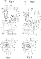
figure 1 is an elevation schematic representation of a supporting device for filling stations of weight filling machines illustrated in a waiting condition of a container to be filled, in accordance with a first embodiment of the present invention; -
figure 2 is a schematic plan representation of a part of the supporting device referred to infigure 1 ; -
figure 3 is an elevation schematic representation of the supporting device referred to infigure 1 , illustrated in an engagement condition of a container to be filled; -
figure 4 is a schematic plan representation of a part of the supporting device depicted infigure 3 ; -
figure 5 is an elevation schematic representation of the supporting device referred to infigure 1 , illustrated in an engagement condition of a container to be with a different format; -
figure 6 is a schematic plan representation of a part of the supporting device depicted infigure 5 ; -
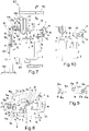
figure 7 is an elevation schematic representation of the supporting device in a waiting condition of a container to be filled, in accordance with a second embodiment of the present invention; -
figure 8 is a schematic plan representation of a part of the supporting device illustrated infigure 7 ; -
figure 9 is an elevation schematic representation of a detail of the supporting device illustrated infigures 7 and 8 ; -
figure 10 is an elevation schematic representation of a part of the supporting device referred to infigures 7 and 8 , illustrated in the engagement condition of a container to be filled; -
figures 11 and 12 are elevation schematic representations of the supporting device illustrated in two different operating conditions, in accordance with a third embodiment of the present invention; -
figures 13 and 14 are elevation schematic representations of the supporting device illustrated in two different operating positions, in accordance with a fourth embodiment of the present invention. - With reference to
figures 1 to 8 andfigures 10 to 14 , a supporting device forfilling stations 100 of weight filling machines (not illustrated in the accompanying figures), in accordance with the present invention is collectively referred to withnumber 1. - As can be seen in
figures 1 to 8 and10 to 14 , the supportingdevice 1 comprises asupport base 2 for supporting a container C to be filled with at least one liquid product. - The
support base 2 is associated with aload cell 101 of afilling station 100 of a weight filling machine to enable and carry out the measurement of the weight of each container C during a filling operation of the same. - Still with reference to
figures 1 to 8 and10 to 14 , the supportingdevice 1 comprises at least onesupport rod 3 extending transversely, preferably perpendicularly, from thesupport base 2. - Since the
support base 2 lies on a substantially horizontal lying plane, thesupport rod 3 extends substantially vertically with respect to thesupport base 2. - As can be seen in
figures 2 ,4 ,6 and8 , thesupport rod 3 has a non-circular cross-sectional profile. Preferably, thesupport rod 3 has a polygonal, even more preferably square, profile in cross-section. However, it should be noted that for the purposes of the present invention, the profile of thesupport rod 3 may also be elliptical or any other shape other than the circular shape. - The supporting
device 1 further comprises at least onesupport mechanism 4 extending transversely, preferably perpendicularly, from thecantilevered support rod 3 on thesupport base 2. - In other words, the
support mechanism 4 extends substantially horizontally in superposition to thesupport base 2. - As can be seen in
figures 1 to 8 and10 to 14 , thesupport mechanism 4 has at least oneengagement portion 5 intended to grip and/or provide a support stop for a container C to be filled with at least one liquid product. - Advantageously, the
support mechanism 4 is movable, preferably by sliding, along thesupport rod 3 between a first minimum distance position, with respect to thesupport base 2 and a second maximum distance position (figures 1 ,3 ,7 and 10 ), with respect to thesupport base 2 so as to adapt to the dimensions, preferably the height, of different containers C to be filled. - In accordance with the embodiments illustrated in
figures 1 to 10 , thesupport mechanism 4 comprises a clamp orclip 6 provided with twobeaks 7 defining, on the opposite side to thesupport rod 3, theengagement portion 5 intended to come into contact with the container C to be filled and, in particular, with a neck or spout A of the latter to retain it in a predetermined position. - The
clamp 6 can be spread apart to prepare theengagement portion 5 of thesupport mechanism 4 to the transverse dimensions of the neck or spout A of the container C to be filled. - As can be seen in
figures 2 ,4 ,6 and8 , in order to allow theclamp 6 to be spread apart, eachbeak 7 is rotatable around an axis of rotation X located on the opposite side with respect to theengagement portion 5, moving away or approaching theother beak 7. Advantageously, eachclamp 6 is also provided with at least oneelastic return member 8, preferably a helical spring or a similar elastic element, operatively interposed between thebeaks 7 in such a way as to counteract the spreading apart of the latter and to ensure the grip of thebeaks 7 on the neck or nozzle A of the container C to be filled. - At the gripping
portion 5, eachbeak 7 has an inclined lead-insurface 7a that allows, on pushing the container C that is being loaded onto thesupport base 2, to spread apart theclamp 6 so that the same can retain the neck or spout A. - Each
beak 7 of theclamp 6 is hinged, on the opposite side with respect to theengagement portion 5, to aslider 9, which slidably engages thesupport rod 3. - In detail, the
slider 9 has a through opening 10 in which thesupport rod 3 is inserted. - Advantageously, the through opening 10 of the
slider 9 has a profile substantially counter-shaped to the profile of the cross section of thesupport rod 3 so that it can slide on the latter without relative rotation between them. - As can be seen in
figures 1 ,3 ,5 ,7, 8, 10 and11 to 14, the supportingdevice 1 further comprises at least onedrive member 11 operatively associated with thesupport mechanism 4 to drive the movement of the latter between the first and second position. - The
drive member 11 comprises at least one supportingstructure 12 having at least a fixedportion 13 and at least oneengaging projection 14 associated with the supportingstructure 12. Theengaging projection 14 of thedrive member 11 has at least oneabutment end 15 arranged to interact with thesupport mechanism 4 to move the latter along thesupport rod 3 at least from the first to the second position. - More and more in detail, the
engaging projection 14 of thedrive member 11 is switchable between a raised position (figures 1 ,7 ,11 and 13 ) wherein thecorresponding abutment end 15 of theengaging projection 14 is at the maximum distance from thesupport base 2 of the supportingdevice 1 and a lowered position (figures 3, 5 ,10 ,12 and 14 ) wherein said abutmentend 15 of theengaging projection 14 is at the minimum distance from thesupport base 2 of the supportingdevice 1. - Advantageously, the
abutment end 15 of theengaging projection 14 of thedrive member 11 engages thesupport mechanism 4, preferably by direct contact, to actuate the latter in movement along thesupport rod 3 from the first to the second position, i.e. upwards, when theengaging projection 14 of thedrive member 11 is switched from the lowered position to the raised position. - The
abutment end 15 of the engagingprojection 14 of thedrive member 11 allows the movement, preferably by gravity, of thesupport mechanism 4 along thesupport rod 3 from the second to the first position, i.e. downwards, when the engagingprojection 14 of thedrive member 11 is switched from the raised position to the lowered position. - More particularly, the switching of the engaging
projection 14 of thedrive member 11 from the raised position to the lowered position allows the movement of thesupport mechanism 4 from the second to the first position until thesupport mechanism 4 intercepts and/or rests on the container C to be filled. - With particular reference to the
support mechanism 4 which provides for aclamp 6 gripping the neck or spout A of the container C to be filled, the switching of the engagingprojection 14 of thedrive member 11 from the raised position to the lowered position disengages theabutment end 15 of the latter from thesupport mechanism 4 which thus rests directly on the container C in such a way as not to distort the measurement of the weight by theload cell 101. - As can be seen in
figures 3, 5 ,10 ,12 and 14 , by translating towards the lowered position, theabutment end 15 of the engagingprojection 14 of thedrive member 11 disengages thesupport mechanism 4 which engages and/or rests on the container C to be filled. Going into further detail, theengagement portion 14 of thedrive member 11 is free to translate along a throughopening 16 formed through aprotrusion 17 of theslider 9 extending transversely, preferably perpendicularly, to thesupport rod 3, on the opposite side to theclamp 6. - The transverse dimensions of the
engagement portion 14 of thedrive member 11 are indeed smaller than the dimensions of the through opening 16 of theprotrusion 17 of theslider 9, so that theengagement portion 14 can translate within it. - Contrary to the
engagement portion 14, the transverse dimensions of theabutment end 15 of the latter are greater than the dimensions of the through opening 16 of theprotrusion 17 of theslider 9, whereby theabutment end 15 can only abut against theprotrusion 17 of theslider 9 or detach from the latter. - The switching of the
engagement portion 14 of thedrive member 11 from the lowered position to the raised position determines the stop of therespective abutment end 15 against theprotrusion 17 of theslider 9 and the possible dragging of the latter along thesupport rod 3 from the first position to the second position. The switching of theengagement portion 14 of thedrive member 11 from the raised position to the lowered position may result in a descent by gravity from the second to the first position of theslider 9 whoseprotrusion 17 rests on theabutment end 15 of theengagement portion 14 until such descent is stopped by the container C to be filled, or the detachment of theabutment end 15 of theengagement portion 14 from theprotrusion 17 of theslider 9 because thesupport mechanism 4 is already engaged to or resting on the container C to be filled. - In accordance with the embodiments illustrated in
figures 1 ,3 ,5 and11 to 14 , thedrive member 11 comprises at least one actuator, preferably linear, even more preferably electric or magnetic or electromagnetic. - In this case, the supporting
structure 12 of thedrive member 11 comprises at least one cylinder which can be fixed to asupport arm 102 of a fillingnozzle 103 of the fillingstation 100 of the respective weight filling machine, and the engagingprojection 14 comprises at least one stem sliding relative to the cylinder to allow the switching of the engagingprojection 14 between the raised position and the lowered position. - In accordance with the embodiment illustrated in
figures 7, 8 and 10 , the supportingstructure 12 comprises at least amovement mechanism 18, preferably with cams, operatively interposed between the fixedportion 13 and the engagingprojection 14 to move the latter between the raised position and the lowered position. - As can be seen in
figures 7 to 9 , themovement mechanism 18 comprises at least onecam profile 19 having at least twosupport surfaces intermediate ramp 19c oblique with respect to saidsupport surfaces - The
cam profile 19 is directly or indirectly supported by the interposition of at least one supportingactuator 20, by the fixedportion 13 of the supportingstructure 12. - The
movement mechanism 18 further comprises at least onefeeler element 21, preferably asupport roller 21a, operatively engaged to thecam profile 19 to travel the latter from asupport surface feeler element 21 is further engaged, for example by means of apin 22, to asupport plate 23 from which the engagingprojection 14 of thedrive member 11 extends so as to also modify the level of thesupport plate 23 and move the engagingprojection 14 of thedrive member 11 between the raised position and the lowered position. - Differently from the embodiments described above, the
engagement portion 14 is fixed with respect to thesupport plate 23 so as to move together with the latter and with thefeeler element 21 between the two levels determined by the support surfaces 19a, 19b of thecam profile 19. - The
upper support surface 19a of thecam profile 19 determines the raised position of the engagingprojection 14, while thesupport surface 19b of thecam profile 19 determines the lowered position of this engagement portion. Theintermediate ramp 19c between the support surfaces 19a, 19b determines the transition of theengagement portion 14 between the raised position and the lowered position. - Advantageously, the
cam profile 19 is adjustable in height to allow the adjustment of the raised and lowered positions of the engagingprojection 14 of thedrive member 11. This feature allows the supportingdevice 1 to be adapted to the different formats and, in particular, to the differences in heights of the containers C to be filled. - In particular, the adjustment of the height of the
cam profile 19 can be implemented by means of anactuator 24, preferably electric, whose cylinder corresponds to the fixedportion 13 of thesupport structure 12 of thedrive member 11 which is installed on asuitable abutment surface 104 and thestem 25 ends with asupport platform 26 which supports thecam profile 19. Still with reference tofigures 7 and 8 , thesupport plate 23 is slidably guided and supported by at least oneguide 27, preferably two or more, engageable with anannular structure 105 of therespective dispensing nozzle 103 or another component of thecorresponding filling station 100 of the weight filling machine. In this way, the ascent and the descent of thefeeler element 21 on thecam profile 19 determines the ascent and the descent of thesupport plate 23 that slides along theguide 27 with respect to the fillingnozzle 103 and the consequent ascent and descent of theengagement element 14 that translates within the through opening 16 of theprotrusion 17 of theslider 9. - In accordance with the embodiments illustrated in
figures 11 to 14 , thesupport mechanism 4 has a monobloc body where theslider 9 and theprotrusion 17 of the latter are almost identical to theslider 9 and theprotrusion 17 of the other embodiments illustrated and described. - Unlike the other embodiments described above that provide for a
clamp 6 to grip the container C to be filled, the embodiments referred to infigures 11 to 14 provide that the monobloc body of thesupport mechanism 4 is provided with aplate 28 extending from theslider 9 on the opposite side to theprotrusion 17 of the latter and ends with anengagement portion 5 intended to rest from above on the neck or spout A of the container C to be filled. - As can be seen in
figures 11 and 12 , theengagement portion 5 is defined by a substantially truncated conicallower recess 29 which is intended to rest on an upper edge B of the neck or spout A of the container C to be filled. - With reference instead to
figures 13 and 14 , theengagement portion 5 is defined by a substantially truncated conicallower protrusion 30 which is intended to be inserted at least partially into a mouth D of the neck or spout A of the container to be filled. - In both cases, the
plate 28 of thesupport mechanism 4 is arranged to rest against the container C when thesupport mechanism 4 slides on thesupport rod 3 from the second to the first position upon movement of theengagement portion 14 of thedrive member 11 from the raised position to the lowered position. The container C remains then blocked in position, between theplate 28 of thesupport mechanism 4 and thesupport base 2 of the supportingdevice 1. - The supporting device and the filling station described above solve the problems encountered in the prior art and allow the achievement of important advantages. First of all, the supporting device described above adapts quickly to formats of containers different from the format of the containers being filled. In fact, when it is necessary to modify the format of the containers to be filled, it is sufficient to adjust the height of the support mechanism of the supporting device along the respective support rod by automatically controlling the drive member of this supporting device.
- If the drive member is of the linear actuator type, the height adjustment of the support mechanism is implemented by lowering or lifting the engagement portion of the drive member and, consequently, of the
slider 9 of the support mechanism. - If the drive member is of the cam-operated mechanism type, it is sufficient to raise or lower, by means of the corresponding actuator, the cam profile, which causes the switching of the engagement member from the raised position to the lowered position and the movement of the support mechanism upwards or downwards along the support rod of the supporting device.
- The supporting device thus conceived eliminates a series of drawbacks that characterize the known solutions.
- In particular, it is no longer necessary to disassemble, adapt and reassemble this device so that it can be adapted to the new format of the containers to be filled, as the adaptation of the supporting device is implemented directly and automatically at the filling place.
- Naturally, this has a huge advantage in terms of time required to implement the format change, which are almost zero if one considers that it is simply an automatic adjustment of the actuators in charge of this task.
- Consequently, the supporting device described above eliminates the very long times of machine downtime normally dedicated to format change.
- It should also be noted that the elimination of machine downtimes for format changes have an extremely positive impact in terms of costs and production times since more containers are filled in the same unit of time.
- In addition, the supporting device described above allows the total elimination of large and voluminous storage spaces or warehouses that were normally dedicated to the supporting devices intended for corresponding formats of containers to be filled.
- This advantage also has a positive impact on overall production costs, as it reduces the costs that were significantly burdensome.
Claims (12)
- Supporting device (1) for filling stations (100) of weight filling machines, comprising:a support base (2) for supporting a container (C) to be filled with at least one liquid product, the support base (2) being associated with a load cell (101) of a filling station (100) of a filling machine for measuring the weight of the container (C) during a filling operation of the same;at least one support rod (3) extending transversely from the support base (2);at least one support mechanism (4) extending transversely from the cantilevered support rod (3) on the support base (2), the support mechanism (4) having at least one engagement portion (5) intended to grip and/or providing a support stop for a container (C) to be filled with at least one liquid product;characterized in that the support mechanism (4) is movable, preferably by sliding along the support rod (3) between a first minimum distance position, with respect to the support base (2) and a second maximum distance position, with respect to the support base (2) so as to adapt to the dimensions, preferably the height, of different containers (C) to be filled.
- Supporting device (1) according to claim 1, also comprising at least one drive member (11) operatively associated with the support mechanism (4) to drive the latter between the first and second position.
- Supporting device (1) according to claim 2, wherein the drive member (11) has:at least one supporting structure (12) having at least a fixed portion (13);at least one engaging projection (14) associated with the supporting structure (12) and having at least one abutment end (15) arranged to interact with the support mechanism (4) to move the latter along the support rod (3) at least from the first to the second position.
- Supporting device (1) according to claim 3, wherein the engaging projection (14) of the actuating member (11) is switchable between a raised position, wherein the corresponding abutment end (15) is at the maximum distance from the support base (2) of the support device (1) and a lowered position wherein said abutment end (15) is at the minimum distance from the support base (2) of the supporting device (1), the abutment (15) of the engaging projection (14) of the actuation member (11) engaging the support mechanism (4), preferably by direct contact, to actuate the latter in movement along the support rod (3) from the first to the second position when the engaging projection (14) of the drive member (11) is switched from the lowered position to the raised position, and allowing the movement, preferably by gravity, of the support mechanism (4) along the support rod (3) to the second to the first position, when the engagement projection (14) of the drive member (11) is switched from the raised position to the lowered position.
- Supporting device (1) according to claim 4, wherein the switching of the engaging projection (14) of the drive member (11) from the raised position to the lowered position allows the movement of the support mechanism (4) from the second to the first position until the support mechanism (4) intercepts and/or rests on the container (C) to be filled, the abutment end (15) of the engagement projection (14) of the actuation member (11) disengaging the support mechanism (4) which engages and/or rests on the container (C) to be filled by moving towards the lowered position.
- Supporting device (1) according to any one of claims 3 to 5, wherein the drive member (11) comprises at least one actuator, preferably a linear actuator, even more preferably electric or magnetic or electromagnetic actuator.
- Supporting device (1) according to any one of claims 2 to 6, wherein the supporting structure (12) of the drive member (11) comprises at least one cylinder which can be fixed to a support arm (102) of a filling nozzle (103) of a respective filling station (100) of a weight filling machine and the engagement projection (14) comprises at least one stem sliding relative to the cylinder to allow the switching of the engagement projection (14) between the raised position and the lowered position.
- Supporting device (1) according to any one of claims 3 to 5, wherein the supporting structure (12) comprises at least a movement mechanism (18), preferably with cams, operatively interposed between the fixed portion (13) and the projection engagement (14) to move the latter between the raised position and the lowered position.
- Supporting device (1) according to claim 8, wherein the movement mechanism (18) comprises:at least one cam profile (19) having at least two supporting surfaces (19a, 19b) arranged on different levels, preferably connected by at least one intermediate ramp (19c) oblique with respect to said support surfaces (19a, 19b), the cam profile (19) being directly or indirectly supported by the interposition of at least one supporting actuator (20), by the fixed portion (13) of the supporting structure (12),at least one feeler element (21), preferably a support roller (21a) operatively engaged to the cam profile (19) to travel the latter from a supporting surface (19a, 19b) to the other, modifying its level, the feeler element (21) being also engaged to a support plate (23) from which the engagement projection (14) of the actuation member (11) extends in so as to also modify the level of the support plate (23) and moving the engaging projection (14) of the actuation member (11) between the raised position and the lowered position.
- Supporting device (1) according to claim 9, wherein the cam profile (19) is adjustable in height to allow the adjustment of the raised and lowered positions of the engagement projection (14) of the actuation member (11) .
- Supporting device (1) according to claim 9 or 10, wherein the support plate (23) is slidably guided and supported by at least one guide (27) engageable with the respective dispensing nozzle (13) or another component of the corresponding machine filler.
- Filling station (100) of a respective weight filling machine, the filling station (100) comprising at least one filling station wherein at least one filling nozzle (103) supported by a corresponding support arm (102) is operatively arranged, the filling station comprising at least one load cell (101) designed to detect the weight of a container (C) to be filled or being filled,
characterized in that it further comprises at least one support device (1) according to any one of the preceding claims for keeping the container (C) to be filled or being filled in a stable position below the corresponding filling nozzle (103).
Applications Claiming Priority (1)
| Application Number | Priority Date | Filing Date | Title |
|---|---|---|---|
| IT102021000018899A IT202100018899A1 (en) | 2021-07-16 | 2021-07-16 | SUPPORT DEVICE FOR FILLING STATIONS OF WEIGHT FILLING MACHINES AND A FILLING STATION EQUIPPED WITH SUCH SUPPORT DEVICE. |
Publications (2)
| Publication Number | Publication Date |
|---|---|
| EP4119492A1 true EP4119492A1 (en) | 2023-01-18 |
| EP4119492B1 EP4119492B1 (en) | 2025-09-03 |
Family
ID=78086750
Family Applications (1)
| Application Number | Title | Priority Date | Filing Date |
|---|---|---|---|
| EP22185179.3A Active EP4119492B1 (en) | 2021-07-16 | 2022-07-15 | Supporting device for filling stations of weight filling machines and a filling station equipped with such a supporting device |
Country Status (3)
| Country | Link |
|---|---|
| EP (1) | EP4119492B1 (en) |
| ES (1) | ES3052402T3 (en) |
| IT (1) | IT202100018899A1 (en) |
Citations (2)
| Publication number | Priority date | Publication date | Assignee | Title |
|---|---|---|---|---|
| EP0616971A1 (en) * | 1993-03-24 | 1994-09-28 | KHS Maschinen- und Anlagenbau Aktiengesellschaft | Filling machine |
| FR2900127A1 (en) * | 2006-04-24 | 2007-10-26 | Pack Realisations Sa | PACKING FILLER WITH CENTERING DEVICE AND SENSOR |
-
2021
- 2021-07-16 IT IT102021000018899A patent/IT202100018899A1/en unknown
-
2022
- 2022-07-15 EP EP22185179.3A patent/EP4119492B1/en active Active
- 2022-07-15 ES ES22185179T patent/ES3052402T3/en active Active
Patent Citations (2)
| Publication number | Priority date | Publication date | Assignee | Title |
|---|---|---|---|---|
| EP0616971A1 (en) * | 1993-03-24 | 1994-09-28 | KHS Maschinen- und Anlagenbau Aktiengesellschaft | Filling machine |
| FR2900127A1 (en) * | 2006-04-24 | 2007-10-26 | Pack Realisations Sa | PACKING FILLER WITH CENTERING DEVICE AND SENSOR |
Also Published As
| Publication number | Publication date |
|---|---|
| IT202100018899A1 (en) | 2023-01-16 |
| ES3052402T3 (en) | 2026-01-07 |
| EP4119492B1 (en) | 2025-09-03 |
Similar Documents
| Publication | Publication Date | Title |
|---|---|---|
| EP3907162B1 (en) | Plant for processing containers | |
| EP3196648B1 (en) | Device for lifting a sample tube | |
| US8266874B2 (en) | Weighing device for a packaging machine | |
| US20110243814A1 (en) | Device for dispensing a product in a petri dish | |
| US7278451B2 (en) | Machine for filling containers | |
| US3648427A (en) | Apparatus for loading frangible containers | |
| CN108313959B (en) | A bottle filling machine | |
| US9340402B2 (en) | Lifting element with extensible rinse sleeve | |
| CN102015492A (en) | Container transfer device including adjustable peripheral guides | |
| CN115803280B (en) | Container handling in capping devices | |
| EP2349886B1 (en) | Device for separating a pallet from the respective load | |
| EP4119492B1 (en) | Supporting device for filling stations of weight filling machines and a filling station equipped with such a supporting device | |
| JP2015044598A (en) | Bagging and packaging method and bagging and packaging machine | |
| EP3927637A1 (en) | Tray supporting device | |
| US3715865A (en) | Capping device for containers | |
| US8530776B2 (en) | De-stacker with a lifter table and welding device for container bodies including a de-stacker | |
| US12466151B2 (en) | Magazine for packs of blanks, and method for making containers from blanks | |
| US5195565A (en) | Variable stroke lifter system | |
| EP0545483A1 (en) | Apparatus for filling containers with a specified amount of liquid | |
| US5117611A (en) | Method and apparatus for packing layers of articles | |
| US4473098A (en) | Container transport device for use with filling equipment | |
| JP4594424B2 (en) | Gravimetric container filling equipment with filling spout inserted into the container | |
| US20210362959A1 (en) | Guiding device as well as gripping and transport device for gripping, holding, guiding and transporting bottle-like containers | |
| JP6933796B2 (en) | Container transport device | |
| US20200361712A1 (en) | Conveyor |
Legal Events
| Date | Code | Title | Description |
|---|---|---|---|
| PUAI | Public reference made under article 153(3) epc to a published international application that has entered the european phase |
Free format text: ORIGINAL CODE: 0009012 |
|
| STAA | Information on the status of an ep patent application or granted ep patent |
Free format text: STATUS: THE APPLICATION HAS BEEN PUBLISHED |
|
| AK | Designated contracting states |
Kind code of ref document: A1 Designated state(s): AL AT BE BG CH CY CZ DE DK EE ES FI FR GB GR HR HU IE IS IT LI LT LU LV MC MK MT NL NO PL PT RO RS SE SI SK SM TR |
|
| STAA | Information on the status of an ep patent application or granted ep patent |
Free format text: STATUS: REQUEST FOR EXAMINATION WAS MADE |
|
| 17P | Request for examination filed |
Effective date: 20230329 |
|
| RBV | Designated contracting states (corrected) |
Designated state(s): AL AT BE BG CH CY CZ DE DK EE ES FI FR GB GR HR HU IE IS IT LI LT LU LV MC MK MT NL NO PL PT RO RS SE SI SK SM TR |
|
| P01 | Opt-out of the competence of the unified patent court (upc) registered |
Effective date: 20230503 |
|
| GRAP | Despatch of communication of intention to grant a patent |
Free format text: ORIGINAL CODE: EPIDOSNIGR1 |
|
| STAA | Information on the status of an ep patent application or granted ep patent |
Free format text: STATUS: GRANT OF PATENT IS INTENDED |
|
| INTG | Intention to grant announced |
Effective date: 20250325 |
|
| GRAS | Grant fee paid |
Free format text: ORIGINAL CODE: EPIDOSNIGR3 |
|
| GRAA | (expected) grant |
Free format text: ORIGINAL CODE: 0009210 |
|
| STAA | Information on the status of an ep patent application or granted ep patent |
Free format text: STATUS: THE PATENT HAS BEEN GRANTED |
|
| AK | Designated contracting states |
Kind code of ref document: B1 Designated state(s): AL AT BE BG CH CY CZ DE DK EE ES FI FR GB GR HR HU IE IS IT LI LT LU LV MC MK MT NL NO PL PT RO RS SE SI SK SM TR |
|
| REG | Reference to a national code |
Ref country code: CH Ref legal event code: EP |
|
| REG | Reference to a national code |
Ref country code: DE Ref legal event code: R096 Ref document number: 602022020601 Country of ref document: DE |
|
| REG | Reference to a national code |
Ref country code: IE Ref legal event code: FG4D |
|
| REG | Reference to a national code |
Ref country code: ES Ref legal event code: FG2A Ref document number: 3052402 Country of ref document: ES Kind code of ref document: T3 Effective date: 20260107 Ref country code: NL Ref legal event code: MP Effective date: 20250903 |
|
| PG25 | Lapsed in a contracting state [announced via postgrant information from national office to epo] |
Ref country code: NO Free format text: LAPSE BECAUSE OF FAILURE TO SUBMIT A TRANSLATION OF THE DESCRIPTION OR TO PAY THE FEE WITHIN THE PRESCRIBED TIME-LIMIT Effective date: 20251203 |
|
| REG | Reference to a national code |
Ref country code: LT Ref legal event code: MG9D |
|
| PG25 | Lapsed in a contracting state [announced via postgrant information from national office to epo] |
Ref country code: FI Free format text: LAPSE BECAUSE OF FAILURE TO SUBMIT A TRANSLATION OF THE DESCRIPTION OR TO PAY THE FEE WITHIN THE PRESCRIBED TIME-LIMIT Effective date: 20250903 |
|
| PG25 | Lapsed in a contracting state [announced via postgrant information from national office to epo] |
Ref country code: HR Free format text: LAPSE BECAUSE OF FAILURE TO SUBMIT A TRANSLATION OF THE DESCRIPTION OR TO PAY THE FEE WITHIN THE PRESCRIBED TIME-LIMIT Effective date: 20250903 |
|
| PG25 | Lapsed in a contracting state [announced via postgrant information from national office to epo] |
Ref country code: GR Free format text: LAPSE BECAUSE OF FAILURE TO SUBMIT A TRANSLATION OF THE DESCRIPTION OR TO PAY THE FEE WITHIN THE PRESCRIBED TIME-LIMIT Effective date: 20251204 |
|
| PG25 | Lapsed in a contracting state [announced via postgrant information from national office to epo] |
Ref country code: SE Free format text: LAPSE BECAUSE OF FAILURE TO SUBMIT A TRANSLATION OF THE DESCRIPTION OR TO PAY THE FEE WITHIN THE PRESCRIBED TIME-LIMIT Effective date: 20250903 |
|
| PG25 | Lapsed in a contracting state [announced via postgrant information from national office to epo] |
Ref country code: LV Free format text: LAPSE BECAUSE OF FAILURE TO SUBMIT A TRANSLATION OF THE DESCRIPTION OR TO PAY THE FEE WITHIN THE PRESCRIBED TIME-LIMIT Effective date: 20250903 |
|
| PG25 | Lapsed in a contracting state [announced via postgrant information from national office to epo] |
Ref country code: BG Free format text: LAPSE BECAUSE OF FAILURE TO SUBMIT A TRANSLATION OF THE DESCRIPTION OR TO PAY THE FEE WITHIN THE PRESCRIBED TIME-LIMIT Effective date: 20250903 Ref country code: PL Free format text: LAPSE BECAUSE OF FAILURE TO SUBMIT A TRANSLATION OF THE DESCRIPTION OR TO PAY THE FEE WITHIN THE PRESCRIBED TIME-LIMIT Effective date: 20250903 |
|
| PG25 | Lapsed in a contracting state [announced via postgrant information from national office to epo] |
Ref country code: RS Free format text: LAPSE BECAUSE OF FAILURE TO SUBMIT A TRANSLATION OF THE DESCRIPTION OR TO PAY THE FEE WITHIN THE PRESCRIBED TIME-LIMIT Effective date: 20251203 |
|
| REG | Reference to a national code |
Ref country code: AT Ref legal event code: MK05 Ref document number: 1832872 Country of ref document: AT Kind code of ref document: T Effective date: 20250903 |
|
| PG25 | Lapsed in a contracting state [announced via postgrant information from national office to epo] |
Ref country code: NL Free format text: LAPSE BECAUSE OF FAILURE TO SUBMIT A TRANSLATION OF THE DESCRIPTION OR TO PAY THE FEE WITHIN THE PRESCRIBED TIME-LIMIT Effective date: 20250903 |
|
| PG25 | Lapsed in a contracting state [announced via postgrant information from national office to epo] |
Ref country code: SM Free format text: LAPSE BECAUSE OF FAILURE TO SUBMIT A TRANSLATION OF THE DESCRIPTION OR TO PAY THE FEE WITHIN THE PRESCRIBED TIME-LIMIT Effective date: 20250903 |
|
| PG25 | Lapsed in a contracting state [announced via postgrant information from national office to epo] |
Ref country code: AT Free format text: LAPSE BECAUSE OF FAILURE TO SUBMIT A TRANSLATION OF THE DESCRIPTION OR TO PAY THE FEE WITHIN THE PRESCRIBED TIME-LIMIT Effective date: 20250903 |
|
| PG25 | Lapsed in a contracting state [announced via postgrant information from national office to epo] |
Ref country code: IS Free format text: LAPSE BECAUSE OF FAILURE TO SUBMIT A TRANSLATION OF THE DESCRIPTION OR TO PAY THE FEE WITHIN THE PRESCRIBED TIME-LIMIT Effective date: 20260103 |
|
| PG25 | Lapsed in a contracting state [announced via postgrant information from national office to epo] |
Ref country code: CZ Free format text: LAPSE BECAUSE OF FAILURE TO SUBMIT A TRANSLATION OF THE DESCRIPTION OR TO PAY THE FEE WITHIN THE PRESCRIBED TIME-LIMIT Effective date: 20250903 Ref country code: PT Free format text: LAPSE BECAUSE OF FAILURE TO SUBMIT A TRANSLATION OF THE DESCRIPTION OR TO PAY THE FEE WITHIN THE PRESCRIBED TIME-LIMIT Effective date: 20260105 |
|
| PG25 | Lapsed in a contracting state [announced via postgrant information from national office to epo] |
Ref country code: SK Free format text: LAPSE BECAUSE OF FAILURE TO SUBMIT A TRANSLATION OF THE DESCRIPTION OR TO PAY THE FEE WITHIN THE PRESCRIBED TIME-LIMIT Effective date: 20250903 Ref country code: EE Free format text: LAPSE BECAUSE OF FAILURE TO SUBMIT A TRANSLATION OF THE DESCRIPTION OR TO PAY THE FEE WITHIN THE PRESCRIBED TIME-LIMIT Effective date: 20250903 |
|
| REG | Reference to a national code |
Ref country code: DE Ref legal event code: R097 Ref document number: 602022020601 Country of ref document: DE |
|
| PG25 | Lapsed in a contracting state [announced via postgrant information from national office to epo] |
Ref country code: LT Free format text: LAPSE BECAUSE OF FAILURE TO SUBMIT A TRANSLATION OF THE DESCRIPTION OR TO PAY THE FEE WITHIN THE PRESCRIBED TIME-LIMIT Effective date: 20250903 |
|
| PG25 | Lapsed in a contracting state [announced via postgrant information from national office to epo] |
Ref country code: DK Free format text: LAPSE BECAUSE OF FAILURE TO SUBMIT A TRANSLATION OF THE DESCRIPTION OR TO PAY THE FEE WITHIN THE PRESCRIBED TIME-LIMIT Effective date: 20250903 |
|
| PGFP | Annual fee paid to national office [announced via postgrant information from national office to epo] |
Ref country code: IT Payment date: 20260421 Year of fee payment: 5 |
|
| PLBE | No opposition filed within time limit |
Free format text: ORIGINAL CODE: 0009261 |
|
| STAA | Information on the status of an ep patent application or granted ep patent |
Free format text: STATUS: NO OPPOSITION FILED WITHIN TIME LIMIT |
|
| REG | Reference to a national code |
Ref country code: CH Ref legal event code: L10 Free format text: ST27 STATUS EVENT CODE: U-0-0-L10-L00 (AS PROVIDED BY THE NATIONAL OFFICE) Effective date: 20260715 |
|
| PGFP | Annual fee paid to national office [announced via postgrant information from national office to epo] |
Ref country code: FR Payment date: 20260608 Year of fee payment: 5 |
|
| 26N | No opposition filed |
Effective date: 20260604 |