EP4119480A1 - Sound system for elevator - Google Patents
Sound system for elevator Download PDFInfo
- Publication number
- EP4119480A1 EP4119480A1 EP20924556.2A EP20924556A EP4119480A1 EP 4119480 A1 EP4119480 A1 EP 4119480A1 EP 20924556 A EP20924556 A EP 20924556A EP 4119480 A1 EP4119480 A1 EP 4119480A1
- Authority
- EP
- European Patent Office
- Prior art keywords
- sound
- car
- speaker
- control unit
- time
- Prior art date
- Legal status (The legal status is an assumption and is not a legal conclusion. Google has not performed a legal analysis and makes no representation as to the accuracy of the status listed.)
- Withdrawn
Links
Images










Classifications
-
- H—ELECTRICITY
- H04—ELECTRIC COMMUNICATION TECHNIQUE
- H04S—STEREOPHONIC SYSTEMS
- H04S7/00—Indicating arrangements; Control arrangements, e.g. balance control
- H04S7/30—Control circuits for electronic adaptation of the sound field
- H04S7/305—Electronic adaptation of stereophonic audio signals to reverberation of the listening space
-
- B—PERFORMING OPERATIONS; TRANSPORTING
- B66—HOISTING; LIFTING; HAULING
- B66B—ELEVATORS; ESCALATORS OR MOVING WALKWAYS
- B66B3/00—Applications of devices for indicating or signalling operating conditions of elevators
-
- B—PERFORMING OPERATIONS; TRANSPORTING
- B66—HOISTING; LIFTING; HAULING
- B66B—ELEVATORS; ESCALATORS OR MOVING WALKWAYS
- B66B11/00—Main component parts of lifts in, or associated with, buildings or other structures
- B66B11/02—Cages, i.e. cars
- B66B11/0226—Constructional features, e.g. walls assembly, decorative panels, comfort equipment, thermal or sound insulation
-
- H—ELECTRICITY
- H04—ELECTRIC COMMUNICATION TECHNIQUE
- H04R—LOUDSPEAKERS, MICROPHONES, GRAMOPHONE PICK-UPS OR LIKE ACOUSTIC ELECTROMECHANICAL TRANSDUCERS; ELECTRIC HEARING AIDS; PUBLIC ADDRESS SYSTEMS
- H04R1/00—Details of transducers, loudspeakers or microphones
- H04R1/02—Casings; Cabinets ; Supports therefor; Mountings therein
-
- H—ELECTRICITY
- H04—ELECTRIC COMMUNICATION TECHNIQUE
- H04R—LOUDSPEAKERS, MICROPHONES, GRAMOPHONE PICK-UPS OR LIKE ACOUSTIC ELECTROMECHANICAL TRANSDUCERS; ELECTRIC HEARING AIDS; PUBLIC ADDRESS SYSTEMS
- H04R1/00—Details of transducers, loudspeakers or microphones
- H04R1/20—Arrangements for obtaining desired frequency or directional characteristics
- H04R1/32—Arrangements for obtaining desired frequency or directional characteristics for obtaining desired directional characteristic only
- H04R1/40—Arrangements for obtaining desired frequency or directional characteristics for obtaining desired directional characteristic only by combining a number of identical transducers
- H04R1/403—Arrangements for obtaining desired frequency or directional characteristics for obtaining desired directional characteristic only by combining a number of identical transducers loud-speakers
-
- H—ELECTRICITY
- H04—ELECTRIC COMMUNICATION TECHNIQUE
- H04R—LOUDSPEAKERS, MICROPHONES, GRAMOPHONE PICK-UPS OR LIKE ACOUSTIC ELECTROMECHANICAL TRANSDUCERS; ELECTRIC HEARING AIDS; PUBLIC ADDRESS SYSTEMS
- H04R1/00—Details of transducers, loudspeakers or microphones
- H04R1/20—Arrangements for obtaining desired frequency or directional characteristics
- H04R1/32—Arrangements for obtaining desired frequency or directional characteristics for obtaining desired directional characteristic only
- H04R1/40—Arrangements for obtaining desired frequency or directional characteristics for obtaining desired directional characteristic only by combining a number of identical transducers
- H04R1/406—Arrangements for obtaining desired frequency or directional characteristics for obtaining desired directional characteristic only by combining a number of identical transducers microphones
-
- H—ELECTRICITY
- H04—ELECTRIC COMMUNICATION TECHNIQUE
- H04R—LOUDSPEAKERS, MICROPHONES, GRAMOPHONE PICK-UPS OR LIKE ACOUSTIC ELECTROMECHANICAL TRANSDUCERS; ELECTRIC HEARING AIDS; PUBLIC ADDRESS SYSTEMS
- H04R2201/00—Details of transducers, loudspeakers or microphones covered by H04R1/00 but not provided for in any of its subgroups
- H04R2201/02—Details casings, cabinets or mounting therein for transducers covered by H04R1/02 but not provided for in any of its subgroups
- H04R2201/021—Transducers or their casings adapted for mounting in or to a wall or ceiling
Definitions
- the present disclosure relates to an audio system for an elevator configured to radiate sound to the inside of a car of the elevator.
- a speaker configured to provide a passenger inside the car with voice guidance is installed.
- an intercom configured for a passenger to, in case of emergency, speak to a person outside the car is installed inside the car.
- a speaker and such an intercom are installed in a car operation panel.
- Patent Literature 1 discloses an elevator configured to send out BGM (background music) as well as voice guidance to the inside of a car.
- This elevator has provided inside a car thereof a speaker and a BGM reproduction device configured to reproduce BGM.
- Patent Literature 2 discloses an elevator having a plurality of speakers placed at regular intervals in a vertically linear fashion.
- This elevator is configured such that in a case in which a car travels upward, audio signals are outputted in sequence to a speaker installed at the uppermost position first and then to a speaker installed at the lowermost position. This gives a passenger the feeling that an audio signal has moved downward.
- this elevator can give a passenger the feeling that the elevator is ascending or descending.
- the elevator disclosed in Patent Literature 1 has one speaker installed inside the car.
- the elevator disclosed in Patent Literature 2 has a plurality of speakers vertically arranged side by side.
- Patent Literatures 1 and 2 do not create stereoscopic sound field environments, nor are they superior in sound quality, as the speakers radiate monaurally reproduced sound.
- Patent Literature 2 is undesirably expensive, as the number of speakers is large.
- the present disclosure has been made to solve such problems and an object thereof is to provide an audio system for an elevator configured to, while having a reduced number of speaker units, form a stereoscopic sound field environment throughout the inside of a car and thereby bring about improvement in sound quality.
- An audio system for an elevator includes two or more speaker cabinets arranged inside a suspended ceiling fixed to a ceiling board of a car of the elevator, an input device to which sound content radiated to an inside of the car from each of the two or more speaker cabinets are input, and a sound field control device configured to conduct a control as phase control and reverberation time control for the sound content and thereby cause a sound wave based on the sound content to be radiated from the speaker cabinet to the inside of the car.
- Each of the speaker cabinets includes a casing arranged inside the suspended ceiling, and a speaker unit arranged inside the casing and having a radiation surface that radiates the sound wave.
- the audio system for an elevator makes it possible to, while having a reduced number of speaker units, form a stereoscopic sound field environment throughout the inside of a car and thereby bring about improvement in sound quality.
- Fig. 1 is a perspective view showing a configuration of an elevator 1 according to Embodiment 1.
- the elevator 1 is installed inside a building and configured to ascend or descend through the inside of a hoistway 2.
- a hoisting machine 3 is provided in an upper part of the hoistway 2.
- the hoisting machine 3 is provided with a sheave 3a. Over the sheave 3a, a main rope 4 is stretched.
- the main rope 4 has two ends coupled to a car 5 and a balancing weight 6, respectively.
- the car 5 and the balancing weight 6 are reversibly suspended from the sheave 3a by the main rope 4.
- an elevator control panel 7 is installed in the upper part of the hoistway 2.
- the elevator control panel 7 is connected to the hoisting machine 3 via a communication line and connected to the car 5 via a control cable 8.
- the control cable 8 transmits electricity and control signals to the car 5.
- the control cable 8 is also referred to as "tail cord".
- the car 5 is formed of four side boards 5a, a floor board 5b, and a ceiling board 5c.
- the four side boards 5a are located on the right, left, front, and back sides, respectively, of the car 5.
- a car door 5d is installed in the front side board 5a of the four side boards 5a. Each time the car 5 stops at an elevator hall on a floor of the building, the car door 5d conducts opening and closing operations in engagement with an elevator hall door (not illustrated) installed in the elevator hall.
- a car control device 9 is installed on an upper surface of the ceiling board 5c of the car 5, as shown in Fig. 1 .
- the car control device 9 conducts control of operation of devices provided in the car 5.
- Examples of the devices provided in the car 5 include the car door 5d, a lighting device 5e (see Fig. 2 ), a car operation panel 5f (see Fig. 2 ), and an audio system 13 for an elevator (see Fig. 3 ).
- the audio system 13 for an elevator is hereinafter simply referred to as "audio system 13".
- a suspended ceiling 10 is fixed.
- the suspended ceiling 10 has a cuboidal shape.
- the suspended ceiling 10 has four side surfaces 10a and a lower surface 10b (see Fig. 2 ). Further, the suspended ceiling 10 may further have an upper surface disposed to face the lower surface 10b.
- the lighting device 5e see Fig. 2
- the audio system 13 see Fig. 3
- a gap 11 of a constant distance D Between the side surfaces 10a of the suspended ceiling 10 and the side boards 5a of the car 5, there is a gap 11 of a constant distance D (see Figs. 2 and 3 ).
- the constant distance D is hereinafter referred to as "first distance D".
- Fig. 1 illustrates a case in which the elevator 1 is a rope elevator, this case is not intended to impose any limitation.
- the elevator 1 may for example be another type of elevator such as a maglev elevator.
- Fig. 2 is a diagram showing an internal appearance of the car 5 of the elevator 1 according to Embodiment 1.
- an internal space of the car 5 is surrounded by the side boards 5a, the floor board 5b, and the lower surface 10b of the suspended ceiling 10.
- the internal space of the car 5 is for example in the shape of a cuboid.
- the floor board 5b is formed of a flat surface placed in a horizontal direction.
- the side boards 5a are formed of flat surfaces placed in a perpendicular direction.
- the term "perpendicular direction" here means, for example, a vertical direction.
- the lower surface 10b of the suspended ceiling 10 is disposed to face the floor board 5b.
- the suspended ceiling 10 is provided with the lighting device 5e.
- the lighting device 5e has its body installed in the internal space of the suspended ceiling 10.
- the lighting device 5e is for example an LED lighting device.
- the lighting device 5e has an illumination surface 5ea facing the floor board 5b.
- the lighting device 5e illuminates the internal space of the car 5 with light shone from the illumination surface 5ea.
- the front side board 5a of the four side boards 5a is provided with the car door 5d. Further, as shown in Fig. 2 , the front side board 5a is provided with the car operation panel 5f.
- the car operation panel 5f is provided with a plurality of car call registration buttons provided separately in correspondence with each floor and door opening and closing buttons configured to control opening and closing operations of the car door 5d.
- the car operation panel 5f is provided with an intercom device 5h configured for a passenger to have outside communications in case of emergency. In addition to being used to have outside communications, the intercom device 5h may also be used to send out a voice message such as "THE DOOR WILL CLOSE" to a passenger.
- the car control device 9 is connected to the elevator control panel 7, for example, via the control cable 8 (see Fig. 1 ).
- the car control device 9 includes an input unit 9a, a control unit 9b, an output unit 9c, a sound field control unit 9d, and a storage unit 9e.
- the input unit 9a inputs control signals from the elevator control panel 7 to the control unit 9b. Based on these control signals, the control unit 9b conducts control of operation of the devices provided in the car 5. Under control of the control unit 9b, the output unit 9c outputs driving signals separately to each of the devices.
- the output unit 9c transmits, to the elevator control panel 7, a signal of, for example, car call registration inputted from a passenger to the car operation panel 5f.
- the sound field control unit 9d is one of the constituent elements of the audio system 13.
- the sound field control unit 9d controls the operation of the audio system 13 to form a stereoscopic sound field with high sound quality throughout the internal space of the car 5.
- the output unit 9c and the sound field control unit 9d form the after-mentioned sound field control device 21.
- a hardware configuration of the car control device 9 is described here. Functions of the input unit 9a, the control unit 9b, the output unit 9c, and the sound field control unit 9d in the car control device 9 are implemented by a processing circuit.
- the processing circuit is formed of dedicated hardware or a processor.
- the dedicated hardware is for example an ASIC (application specific integrated circuit), an FPGA (Field Programmable Gate Array), or other hardware.
- the processor executes a program stored in a memory.
- the storage unit 9e is formed of the memory.
- the memory is a nonvolatile or volatile semiconductor memory such as a RAM (random-access memory), a ROM (read-only memory), a flash memory, or an EPROM (erasable programmable ROM) or a disc such as a magnetic disc, a flexible disc, or an optical disc.
- a RAM random-access memory
- ROM read-only memory
- flash memory or an EPROM (erasable programmable ROM)
- disc such as a magnetic disc, a flexible disc, or an optical disc.
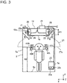
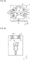
- Fig. 3 is a front view showing a configuration of the audio system 13 according to Embodiment 1.
- Fig. 4 is a top view showing an arrangement of speaker cabinets 20 of the audio system 13 according to Embodiment 1.
- a direction parallel with the height of the car 5 is a Y direction
- a direction parallel with the width of the car 5 is an X direction
- a direction parallel with the depth of the car 5 is a Z direction.
- the Y direction is for example a vertical direction.
- the right, left, front, and back of the inside of the car 5 are defined such that the X direction is a direction from side to side of the car 5 and the Z direction is a direction toward both the front and back of the car 5.
- the audio system 13 is formed of one or more speaker cabinets 20, a sound field control device 21, and an input device 22.
- the audio system 13 radiates sound to a passenger in the car 5.
- Embodiment 1 uses, as the sound, sound content, such as the murmur of a river or the chirping of a bird, that calls up an image of nature is used as the sound.
- the number of speaker cabinets 20 is 2.
- the number of speaker cabinets 20 is not limited to this number but may be any number larger than or equal to 1.
- each of the speaker cabinets 20 is installed the internal space of the suspended ceiling 10.
- Each of the speaker cabinets 20 is formed of a speaker unit 23 and a casing 25.
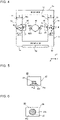
- Fig. 5 is a side view showing a configuration of an example of a speaker cabinet 20 according to Embodiment 1.
- Fig. 6 is a front view of the speaker cabinet 20 of Fig. 5 .
- the speaker unit 23 is accommodated in the casing 25.
- the speaker unit 23 has provided on a front surface 25a of the casing 25 a radiation surface 23a that radiates sound.
- the casing 25 has, for example, a cuboidal shape.
- the casing 25 is a closed apparatus.
- the radiation surface 23a of the speaker unit 23 is exposed outward through an installation hole provided in the casing 25.
- Other parts of the speaker unit 23 are all installed inside the casing 25. Accordingly, the sound from the radiation surface 23a of the speaker unit 23 is radiated only in the direction of an arrow A in Fig. 5 , and is not radiated outward via the other parts of the casing 25 other than the radiation surface 23a.
- Fig. 7 is a side view showing a configuration of another example of a speaker cabinet 20 according to Embodiment 1.
- Fig. 8 is a front view of the speaker cabinet 20 of Fig. 7 .
- the speaker cabinet 20 may have two or more speaker units 23 accommodated inside the casing 25.
- one speaker unit 23-1 may be a full-range speaker
- the other speaker unit 23-2 may be a tweeter.
- the term "full-range speaker” means a speaker configured to reproduce a low-to-high range with one speaker.
- one speaker unit 23 accommodated inside the casing 25 of a speaker cabinet 20 is a full-range speaker.
- the term "tweeter” means a speaker dedicated to a low range for use as an aid to a full-range speaker. It is difficult to reproduce a low-to-high range with one speaker, and doing so may result in poor sound quality. In such a case, a tweeter is used to compensate for the poor sound quality.
- the two or more speaker units 23 arranged inside the casing 25 may be of different types or may be of the same type. In such a case in which one speaker cabinet 20 includes a plurality of speaker units 23, a feeling of sound quality can be improved and a wider band can be reproduced with the speaker cabinet 20 alone.
- the speaker cabinets 20 are arranged in the internal space of the suspended ceiling 10.
- the height of the suspended ceiling 10 in the Y direction i.e. the direction parallel with the height of the car 5) is approximately 5 cm.
- the height H1 of the casing 25 of each of the speaker cabinets 20 in the Y direction i.e. the direction parallel with the height of the car 5) is less than or equal to 5 cm.
- the radiation surface 23a of the speaker unit 23 is disposed to face a side board 5a of the car 5.
- the radiation surface 23a is located along an edge of a side surface 10a of the suspended ceiling 10.
- the radiation surface 23a is located in the same plane as the side surface 10a of the suspended ceiling 10. Accordingly, the position of the radiation surface 23a in the X direction (i.e. the direction parallel with the width of the car 5) agrees or substantially agrees with the position of the side surface 10a of the suspended ceiling 10 in the X direction.
- the side surface 10a of the suspended ceiling 10 is provided with an opening in alignment with the position of the radiation surface 23a. It should be noted that the side surface 10a of the suspended ceiling 10 may be entirely in an open state. Accordingly, the sound radiated from the radiation surface 23a is not insulated by the side surface 10a of the suspended ceiling 10.
- the speaker unit 23 conducts "indirect sound radiation" by which the speaker unit 23 radiates sound to a passenger through the use of reflection off the side board 5a of the car 5.
- each of the speaker cabinets 20 is located in a central portion of the suspended ceiling 10 in the Z direction (i.e. the direction parallel with the depth of the car 5). Further, as shown in Fig. 3 , each of the speaker cabinets 20 is located in a central portion of the suspended ceiling 10 in the Y direction (i.e. the direction parallel with the height of the car 5).
- the speaker unit 23 provided in one of the two speaker cabinets 20 shown in Fig. 4 is referred to as "speaker unit 23R". Further, the speaker unit 23 provided in the speaker cabinet 20 is referred to as “speaker unit 23L”.
- the speaker unit 23R and the speaker unit 23L are placed at a clearance from each other.
- the speaker unit 23R and the speaker unit 23L are arranged so that their respective back surfaces face each other.
- the radiation surface 23a of the speaker unit 23R is disposed to face the right side board 5a of the car 5. Meanwhile, the radiation surface 23a of the speaker unit 23L is disposed to face the left side board 5a of the car 5.
- Each of the radiation surfaces 23a of the speaker units 23R and 23L is disposed to face the gap 11.
- Each of the radiation surfaces 23a of the speaker units 23R and 23L is located in the same plane as a corresponding one of the right and left side surfaces 10a of the suspended ceiling 10.
- each of the speaker units 23 reproduces sound pressures lying within a frequency band ranging, for example, from 150 Hz to 48 kHz. That is, sound of a low frequency lower than 150 Hz is not used. A reason for this is explained.
- the inside of the car 5 is an enclosed space. Therefore, a low-frequency component of a long wavelength is reflected more than once among the side boards 5a of the inside of the car 5. This results in a long reflection time, a persistent standing wave, and a long reverberation time.
- a standing wave generated by the reflection of sound is hereinafter referred to as "echo".
- echo A standing wave generated by the reflection of sound
- Embodiment 1 is required to reproduce a band of frequencies higher than or equal to 150 Hz. This makes it possible to avoid giving the passenger a feeling of discomfort and give the passenger comfort. Further, as for a high-frequency component, a frequency band compatible with 96 kHz/24 bit is rendered reproducible for the purpose of providing high sound quality with high resolution based on a high-resolution sound source. Embodiment 1 assumes a band of frequencies lower than or equal to 48 kHz, which is half as high as 96 kHz/24 bit.
- the sound field control device 21 is located inside the car control device 9 provided on the upper surface of the ceiling board 5c of the car 5. As shown in Fig. 2 , the sound field control device 21 includes the output unit 9c and the sound field control unit 9d. Further, the sound field control device 21 further includes a power source (not illustrated). The sound field control unit 9d is provided with a sound field control substrate.
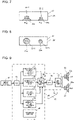
- Fig. 9 is a block diagram showing a configuration of the sound field control device 21 according to Embodiment 1.
- the sound field control device 21 includes the output unit 9c and the sound field control unit 9d.
- the output unit 9c includes a D/A converter 36 and an amplifier 37.
- the D/A converter 36 converts a digital signal into an analog signal and outputs the analog signal.
- the amplifier 37 amplifies the analog signal outputted from the D/A converter 36.
- the analog signal outputted from the amplifier 37 is transmitted to each of the speaker units 23.
- the speaker unit 23 radiates the analog signal as sound from the radiation surface 23a.
- the sound field control unit 9d includes an A/D converter 30, a propagation characteristic control unit 31, a directivity control unit 32, a delay control unit 33, a reverberation time control unit 34, a synthesizing unit 35, and a storage device 39.
- the storage device 39 may be part of the storage unit 9e shown in Fig. 2 , or may be formed of another memory.
- the A/D converter 30 is supplied with an input signal 38 inputted from the input device 22.
- the input signal 38 is an analog signal.
- the input signal 38 is the aforementioned sound content.
- the A/D converter 30 converts the analog signal into a digital signal and outputs the digital signal.
- the digital signal outputted from the A/D converter 30 is inputted to the propagation characteristic control unit 31, the directivity control unit 32, the delay control unit 33, and the reverberation time control unit 34.
- the propagation characteristic control unit 31 conducts time-axis crosstalk phase component control on the digital signal outputted from the A/D converter 30.
- a sound radiation component hereinafter referred to as "cross sound”
- cross sound a sound radiation component propagating indirectly to the right and left ears of a passenger is attenuated according to indoor environmental characteristics. This causes a sound field to be expanded. Details will be described later.
- the directivity control unit 32 conducts in-phase linear phase control on the digital signal outputted from the A/D converter 30.
- the direction of sound radiated from the speaker unit 23 at each arbitrary angle is time-axially controlled, whereby in-phase radiated sound is produced. This brings about a surround-sound effect by which the sound can be heard in the same way anywhere inside the car 5. Details will be described later.
- the delay control unit 33 conducts linear phase control on the digital signal outputted from the A/D converter 30.
- linear phase control deterioration in sound quality due to a delay in propagation time at each frequency is eliminated by conducting control so that sounds lying within an entire frequency band simultaneously reach a passenger. Details will be described later.
- the reverberation time control unit 34 conduct a control as reverberation time control on the digital signal outputted from the A/D converter 30.
- the reverberation time control involves control that reduces the reverberation time of an echo produced by reflection. As mentioned above, sound is repeatedly reflected off walls in an enclosed space such as the car 5. This causes the sound to untunefully echo, resulting in poor clarity of sound. Therefore, the reverberation time control involves control that reduces the reverberation time of sound, thereby making the sound heard clearly. Details will be described later.
- the synthesizing unit 35 synthesizes digital signals outputted from the propagation characteristic control unit 31, the directivity control unit 32, the delay control unit 33, and the reverberation time control unit 34.
- a synthesized digital signal outputted from the synthesizing unit 35 is inputted to the aforementioned D/A converter 36.
- the synthesizing unit 35 synthesizes digital signals outputted from the propagation characteristic control unit 31, the directivity control unit 32, the delay control unit 33, and the reverberation time control unit 34.
- this case is not intended to impose any limitation, and the synthesizing unit 35 may not be provided.
- the propagation characteristic control unit 31, the directivity control unit 32, the delay control unit 33, and the reverberation time control unit 34 may conduct processes in sequence so that a digital signal outputted from the reverberation time control unit 34 is emitted from the speaker unit 23.
- the directivity control unit 32 it is not always necessary to conduct all processes in the propagation characteristic control unit 31, the directivity control unit 32, the delay control unit 33, and the reverberation time control unit 34. At least one of the processes in the propagation characteristic control unit 31, the directivity control unit 32, the delay control unit 33, and the reverberation time control unit 34 may be conducted on an as-needed basis.
- the input device 22 is accommodated inside a hinged door 5g provided in a side board 5a inside the car 5. Under normal circumstances, the hinged door 5g is closed and never touched by a passenger.
- the input device 22 is provided with a USB connector 22a and a volume controller 22b.
- a USB memory having stored therein sound source data representing the sound content is connected.
- the volume controller 22b is operated by a worker to set a volume level.
- the audio system 13 generates a sound field 27 ranging as indicated by dotted lines in Fig. 3 .
- the height H2 of a lower limit 27a of the sound field 27 is for example 1.6 m above the floor board 5b of the car 5.
- the height of an upper limit of the sound field 27 is for example 1.8 m above the floor board 5b of the car 5. It is desirable that the sound field 27 be formed so that a height above the floor board 5b falls within a range of 1.6 m to 1.8 m.
- the sound field 27 is generated in a portion of the inside of the car 5 that is higher than the lower limit 27a. This results in causing the sound field 27 to be formed around the head of a passenger as shown in Fig. 3 .
- the range of heights of 1.6 m to 1.8 m above the floor board 5b is equivalent to the average positions of the ears of passengers.
- a favorable sound field cannot be formed in a case in which a plurality of passengers are riding inside the car 5, as sound is insulated or absorbed by the bodies of the passengers.
- a passenger auditorily feels it is hard to hear the sound, as the sound field 27 is unevenly formed over the head of the passenger.
- elevators include a speaker configured to give a voice message or an alarm in case of emergency, a speaker configured to notify passengers at which floor the elevator has arrived, and an intercom configured to have outside communications.
- Some models of elevators reproduce music through a speaker for an intercom for the comfort of passengers.
- the speaker of the intercom is usually placed in an operation panel inside the car. Due to limitations of space inside the operation panel, the speaker of the intercom is required to have features such as light weight, low profile, small size, and monaural reproduction. Accordingly, reproduced sound from the speaker of the intercom is very poor in sound quality, and such radiated sound is clearly different from that of music being reproduced by a household audio device.
- the audio system 13 is intended for elevator users to use elevators without constraint, and is intended to provide a comfortable space inside the car 5 during use.
- the audio system 13 provides a stereoscopic sound space such as a movie theater so that passengers inside the car 5 can feel that the inside of the car 5 is a large space such as an open field.
- the audio system 13 provides passengers inside the car 5 with a "realistic feeling of being in a large and comfortable space” so that they feel as if a small space were a large space. This allows elevator users to use elevators with a good feeling.
- the audio system 13 uses two speaker units 23 to provide a realistic feeling of being in a large and comfortable space.
- the audio system 13 achieves high-quality sound reproduction with a reduced number of speaker units 23.
- the propagation characteristic control unit 31 controls, based on a difference in propagation time between a direct sound arriving at one of a pair of virtual microphones 40 and a cross sound arriving at the other of the pair of virtual microphones 40 when a sound wave radiated from the radiation surface 23a of each of the speaker units 23 arrives at the pair of virtual microphones 40, the propagation characteristic of the sound wave.
- Fig. 10 is a top view showing a model of a relationship between the speaker units 23 and the microphones 40 in the audio system 13 according to Embodiment 1.
- the passenger model 42 is a life-size model of an ordinary passenger.
- a microphone 40R is installed in the right ear of the passenger model 42
- a microphone 40L is installed in the left ear of the passenger model 42.
- additional microphones 41R and 41L may be further installed above the microphones 40R and 40L, respectively, if necessary.
- the following gives a description by taking, as an example, a case in which only the microphones 40R and 40L are installed.
- the speaker unit 23 installed on the right front side of the passenger model 42 is referred to as “speaker unit 23R”.
- the speaker unit 23 installed on the left front side of the passenger model 42 is referred to as “speaker unit 23L”.
- sound radiated from the speaker unit 23R turns into a direct sound R (reference sign 43) and a cross sound RL (reference sign 44) that arrive at the microphones 40R and 40L, respectively.
- the direct sound R reference sign 43
- the cross sound RL reference sign 44
- the microphone 40L after propagating for a given period of time from the speaker unit 23R.
- Fig. 11 is a diagram showing the waveforms of direct sounds and cross sounds according to Embodiment 1.
- Fig. 11 shows the waveforms of the direct sound R (reference sign 43) received by the microphone 40R, the direct sound L (reference sign 45) received by the microphone 40L, the cross sound RL (reference sign 44) received by the microphone 40L, and the cross sound LR (reference sign 46) received by the microphone 40R.
- the horizontal axis represents time
- the vertical axis represents phase. As can be seen from Fig. 11 , these four sounds arrive at different times.
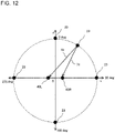
- Fig. 12 is a top view showing a model of a relationship between the speaker units 23 and the microphones 40.
- Fig. 12 shows a case in which sound is being radiated from any one of the plurality of speaker units 23.
- the microphones 40R and 40L are placed at a constant distance from each other on the x axis with the origin at the center.
- the plurality of speaker units 23 are arranged on the circumference of a circle centered at the origin. The position of each of the speaker units 23 is identified by an angle with the positive direction of the y axis being 0 deg. and the positive direction of the x axis being 90 deg.
- Y1 is the propagation time it takes for a sound wave 70 to propagate from the speaker unit 23 to the microphone 40L
- Y2 is the propagation time it takes for a sound wave 71 to propagate from the speaker unit 23 to the microphone 40R, with the speed of sound being 340 m/s.
- the sound wave 70 arrives at the microphone 40L with a delay time (Y1 - Y2).
- a sound wave from the speaker unit 23 arrives at the microphones 40R and 40L at the same point in time, so that the delay time (Y1 - Y2) is equal to 0.
- the delay time (Y1 - Y2) reaches its maximum. That is, in the case of a speaker unit 23 located at 90 deg., a sound wave arrives at the microphone 40R fastest but arrives at the microphone 40L latest. Further, in the case of a speaker unit 23 located at 270 deg., a sound wave arrives at the microphone 40L fastest but arrives at the microphone 40R latest.
- the delay time (Y1 - Y2) varies from the position of one speaker unit 23 to the position of another speaker unit 23. Accordingly, the delay time (Y1 - Y2) can be measured in advance for each of the positions of the speaker units 23 by sending out test sound through the speaker unit 23. Moreover, by the delay time (Y1 - Y2) thus measured, the waveform of the sound wave 71 arriving at the microphone 40R is made later than the waveform of the sound wave 70 arriving at the microphone 40L. This allows the waveform of the sound wave 70 arriving at the microphone 40R and the waveform of the sound wave 71 arriving at the microphone 40L to coincide with each other regardless of the position of the speaker unit 23.
- the propagation characteristic control unit 31 utilizes this principle to conduct the following process to obtain four waveforms shown in Fig. 13 from the four waveforms shown in Fig. 11 .
- Fig. 13 is a diagram showing the waveforms of sound waves outputted from the propagation characteristic control unit 31 provided in the audio system 13 according to Embodiment 1.
- the horizontal axis represents time
- the vertical axis represents phase.
- the microphone 40R is installed in the right ear of the passenger model 42, and the microphone 40L is installed in the left ear of the passenger model 42.
- a binaural measurement is conducted by sending out test sound through the two speaker units 23 installed in position as shown in Fig. 4 and receiving the test sound with the microphones 40R and 41L.
- the test sound used here is white noise an entire frequency band of which has been subjected to signal processing at the same sound pressure level.
- the speaker unit 23 on the right side of the passenger model 42 is referred to as "speaker unit 23R”
- the speaker unit 23 on the left side of the passenger model 42 is referred to as "speaker unit 23L”.
- the test sound is reproduced from the speaker units 23 in the order of the speaker unit 23R alone, the speaker unit 23L alone, and then both the speaker units 23R and 23L.
- the test sound is sequentially reproduced from one or the other of the two speaker units 23 and then simultaneously reproduced from both of the two speaker units 23. This reproduction makes it possible to acquire information on radiation characteristics observed inside the car 5 when the test sound is radiated separately from each speaker unit 23 and information on radiation characteristics observed inside the car 5 when the test sound is radiated simultaneously from all speaker units 23.
- a delay time of the cross sound RL (reference sign 44) with respect to the direct sound R (reference sign 43) is calculated based on these four waveforms 43 to 46 of sound waves. This delay time is referred to as "first delay time”.
- a delay time of the cross sound LR (reference sign 46) with respect to the direct sound L (reference sign 45) is calculated based on these four waveforms 43 to 46 of sound waves. This delay time is referred to as "second delay time”.
- the first delay time and the second delay time are stored in a storage device (not illustrated) of the audio system 13.
- the propagation characteristic control unit 31 calculates the absolute value of a negative phase component 47 of the direct sound R (reference sign 43) shown in Fig. 11 and adds the absolute value to a positive phase component 48 of the direct sound R (reference sign 43). Similarly, the propagation characteristic control unit 31 calculates the absolute value of a negative phase component 47 of the direct sound L (reference sign 45) and adds the absolute value to a positive phase component 48 of the direct sound L (reference sign 45). Further, the propagation characteristic control unit 31 also conducts similar processes on the cross sound RL (reference sign 44) and the cross sound LR (reference sign 46).
- the propagation characteristic control unit 31 controls the amplitude and phases of the waveform of the direct sound R (reference sign 43) and the direct sound L (reference sign 45) and thereby makes the waveforms uniform in amplitude and phase. Furthermore, the propagation characteristic control unit 31 controls the amplitude and phases of the waveform of the cross sound RL (reference sign 44) and the cross sound LR (reference sign 45) and thereby makes the waveforms uniform in amplitude and phase. Further, in Fig. 11 , a comparison between the direct sound R (reference sign 43) received by the microphone 40R and the cross sound RL (reference sign 44) received by the microphone 40L shows that there is not only a difference in propagation time but also a clear difference in sound pressure level.
- a comparison between the direct sound L (reference sign 45) and the cross sound LR (reference sign 46) shows that there is not only a difference in propagation time but also a clear difference in sound pressure level. Accordingly, the propagation characteristic control unit 31 conducts control that makes the waveform of the direct sound R (reference sign 43) and the cross sound RL (reference sign 44) uniform in amplitude. Similarly, the propagation characteristic control unit 31 conducts control that makes the waveform of the direct sound L (reference sign 45) and the cross sound LR (reference sign 46) uniform in amplitude.
- the waveform of the direct sound R (reference sign 43) is made later than the waveform of the cross sound RL (reference sign 44) by the first delay time.
- the waveform of the direct sound L (reference sign 45) is made later than the waveform of the cross sound RL (reference sign 46) by the second delay time.
- the cross sound RL (reference sign 44) and the cross sound RL (reference sign 46) are radiated earlier.
- the direct sound R (reference sign 43) and the direct sound L (reference sign 45) are radiated the first delay time and the second delay time later, respectively.
- a component of cross sound causes a sound image of sound radiated from the speaker units 23 to be heard intensively in the center of the cross component, that is, in between the right and left ears of a passenger.
- the cross sound is radiated first, and then the direct sound is radiated with a time difference. Phase characteristics accompanying the sound radiation of the cross sound and the direct sound need to be made uniform so that the phase characteristics never become opposite in phase.
- the propagation characteristic control unit 31 makes a phase adjustment. This makes it possible to give the passenger a feeling of migration of sound with the cross sound radiated earlier and give the passenger a feeling of localization of sound with the direct sound radiated later. This results in enabling the passenger to, without feeling a sense of incongruity as if the sound field passed only over the head of the passenger, hear the sound radiated with the feeling of migration and the feeling of localization obtained from the uniform phase.
- the propagation characteristic control unit 31 stores the first delay time and the second delay time in advance in the storage device 39.
- the propagation characteristic control unit 31 causes the direct sound R (reference sign 43) and the direct sound L (reference sign 45) to be radiated later than the cross sound RL (reference sign 44) and the cross sound RL (reference sign 46) the first delay time and the second delay time, respectively.
- the propagation characteristic control unit 31 uses filter processes such as FIR (finite impulse response) and IIR (infinite impulse response) as the processes for making amplitude and phases uniform and the processes for delaying the timing of radiation. This makes it possible to generate the sound field 27 inside the car 5 with a feeling of high sound quality.
- the passenger model 42 is temporarily installed for testing. Therefore, the passenger model 42 is removed during actual operation of the elevator 1. Accordingly, the microphones 40R and 40L too are removed during actual operation of the elevator 1. Accordingly, the terms such as "propagation time” and “delay time” in the foregoing description refer to times based on the assumption that the microphones 40R and 40L are installed. Therefore, during actual operation, the "propagation time” and the “delay time” are for virtual microphones.
- the directivity control unit 32 is described.
- the directivity control unit 32 time-axially controls, for each angle according to the orientation of a passenger, the direction of sound radiated from each of the speaker units 23 and thereby produces in-phase radiated sound. This brings about a surround-sound effect by which the sound can be heard in the same way anywhere inside the car 5. That is, the directivity control unit 32 controls, based on the angle of radiation of a sound wave radiated from the radiation surface 23a of the speaker unit 23, the directivity of the sound wave.
- in-phase linear phase control that is conducted in the directivity control unit 32 is illustrated.
- faithful transmission of a signal requires so-called linear phase characteristics according to which the phase characteristics of the signal linearly change with frequency.
- linear phase circuits are commonly used.
- the directivity control unit 32 too uses a linear phase circuit to achieve linear phase characteristics. Note, however, that the directivity control unit 32 uses, for example, a delay circuit in addition to the linear phase circuit to time-axially control, for each angle of radiation of a sound wave, the direction of sound radiated from the speaker unit 23.
- Fig. 14 is a model diagram showing a case in which the two speaker units 23R and 23L are placed at a constant distance d from each other.
- the angle ⁇ is an angle of inclination of a microphone 40 with respect to the central axis of the speaker units 23.
- ⁇ is a wavelength
- ⁇ R is the phase of the speaker unit 23R
- ⁇ L is the phase of the speaker unit 23L.
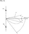
- Fig. 15 is a model diagram showing a sound radiation pattern of a synthetic sound pressure 72 formed by the two speaker units 23R and 23L.
- the synthetic sound pressure 72 has a peak direction displaced toward the speaker unit 23L by an angle ⁇ from the central axis.
- the synthetic sound pressure 72 becomes inappropriate in sound radiation direction, so that optimum sound reproduction cannot be achieved.
- the directivity control unit 32 time-axially controls the direction of sound radiated from each of the speaker units 23R and 23L and thereby creates in-phase radiated sound. For that purpose, the directivity control unit 32 sends out test sound through the speaker units 23R and 23L with varying angles of the microphone 40. Then, the directivity control unit 32 measures the direction of radiated sound at each angle.
- the test sound involves the use of an impulse response.
- Fig. 16 is a diagram showing a state in which test sound is sent out by the directivity control unit 32 provided in the audio system 13 according to Embodiment 1.
- the passenger model 42 is fitted with the microphones 40R and 40L.
- the passenger model 42, fitted with the microphones 40R and 40L, is rotated in 90-degree increments as shown in (a) to (d) of Fig. 16 .
- test sound radiated from the speaker units 23R and 23L is measured with the microphone 40R and 40L in the four states shown in (a) to (d) of Fig. 16 .
- the test sound may be measured with the passenger model 42 installed at a different directivity angle other than those of (a) to (d) of Fig. 16 .
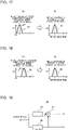
- Fig. 17 is a diagram showing phase signals of a first directivity angle P before and after control by the directivity control unit 32 according to Embodiment 1.
- (a) of Fig. 17 shows a phase signal 80 before control
- (b) of Fig. 17 shows a phase signal 81 after control.
- Fig. 17 takes a case of 0 deg. to 90 deg. as an example.
- the horizontal axis represents time
- the vertical axis presents the voltages of the phase signals.
- the directivity control unit 32 converts the phase signal 80 shown in (a) of Fig. 17 into the phase signal 81 shown in (b) of Fig. 17 by shifting the phase signal 80 shown in (a) of Fig. 17 by a particular delay time as indicated by an arrow E. Specifically, the directivity control unit 32 delays the peak time of the phase signal 80 shown in (a) of Fig. 17 so that the peak time coincides with a reference time shown in (b) of Fig. 17 . It should be noted that this particular delay time is a period of time determined for each directivity angle based on the results of the measurements of the test sound shown in (a) to (d) of Fig. 16 described above. Further, the delaying processes involves the use of, for example, a delay circuit 52 (see Fig. 19 ).
- Fig. 18 is a diagram showing phase signals of a second directivity angle Q before and after control by the directivity control unit 32 according to Embodiment 1.
- (a) of Fig. 18 shows a phase signal 82 before control
- (b) of Fig. 18 shows a phase signal 83 after control.
- Fig. 18 takes a case of 90 deg. to 180 deg. as an example.
- the horizontal axis represents time
- the vertical axis presents the voltages of the phase signals.
- the directivity control unit 32 converts the phase signal 82 shown in (a) of Fig. 18 into the phase signal 83 shown in (b) of Fig. 18 by shifting the phase signal 82 shown in (a) of Fig.
- the directivity control unit 32 hastens the peak time of the phase signal 82 shown in (a) of Fig. 18 by a period of time equivalent to the particular delay time so that the peak time coincides with a reference time shown in (b) of Fig. 18 .
- this particular delay time is a period of time determined for each angle based on the results of the measurements of the test sound shown in (a) to (d) of Fig. 16 described above.
- a comparison between the phase signal 81 after control of (b) of Fig. 17 and the phase signal 83 after control of (b) of Fig. 18 shows that the peak times of the two phase signals 81 and 83 both coincide with the reference time.
- the directivity control unit 32 conducts controls that, based on an angle formed by the direction of directivity of a sound wave radiated from the radiation surface 23a of the speaker unit 23 and the direction of installation of a microphone 40, causes the peak time of a sound pressure of the sound wave to coincide with a reference time. This brings about a surround-sound effect by which the sound can be heard in the same way anywhere inside the car 5.
- the directivity control unit 32 causes the peak times of all phase signals to coincide with the reference time, this case is not intended to impose any limitation.
- the directivity control unit 32 may cause one of the peak times to coincide with the other of the peak times. That is, for example, the directivity control unit 32 may cause the peak time of the phase signal 80 of (a) of Fig. 17 to coincide with the peak time of the phase signal 82 of (a) of Fig. 18 .
- Fig. 19 is a diagram showing an example of a configuration of the directivity control unit 32 according to Embodiment 1.
- the linear phase circuit is formed of a low-pass filter 50 and a subtracter 51.
- an input signal is divided into two signals. One of the two signals is outputted through the low-pass filter 50. The other of the two signals is inputted to the subtracter 51.
- the subtracter 51 subtracts, from the signal inputted to the subtracter 51, the signal having passed through the low-pass filter 50.
- the directivity control unit 32 includes the delay circuit 52 in addition to the linear phase circuit.
- the delay circuit 52 delays a signal by a delay time at each angle determined by the directivity control unit 32 and outputs the signal.
- the delay control unit 33 is described. To eliminate deterioration in sound quality due to a delay in propagation time at each frequency, the delay control unit 33 conducts linear phase control so that sounds of all frequencies simultaneously reach a passenger. That is, the delay control unit 33 controls a delay in propagation time derived from the frequency of a sound wave radiated from the radiation surface 23a of each of the speaker units 23. Specifically, the delay control unit 33 stores propagation times in advance in the storage device 39 separately for each of the frequencies of sound waves.
- the delay control unit 33 controls the timing of radiation of those sound waves based on the propagation time of the sound wave at each frequency so that the peaks of the phases of the sound waves of the plurality of frequencies coincide.
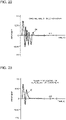
- Fig. 20 is a diagram showing the waveforms of sounds received by the microphone 40R or 40L according to Embodiment 1.
- the horizontal axis represents time
- the vertical axis represents phase.
- a waveform 61 of a sound with a frequency of 500 Hz arrives at the microphone 40 later than a waveform 60 of a sound with a frequency of 1 kHz. That is, a propagation time 62 of the waveform 60 is shorter than a propagation time 63 of the waveform 61.
- the delay control unit 33 By sending out test sound through the speaker unit 23 and receiving the test sound through the microphone 40, the delay control unit 33 measures the propagation time of the sound at each frequency and stores the propagation time in advance in the storage device 39. For all sounds of different frequencies to simultaneously reach, the delay control unit 33 conducts control so that the propagation times of those sounds coincide. Specifically, the delay control unit 33 emits the sound of the waveform 60 the speaker unit 23 with a delay by a time difference ⁇ t between the propagation time 63 and the propagation time 62. This results in causing the waveforms 60 and 61 to reach their respective peak values at the same point in time as shown in Fig. 21.
- Fig. 21 is a diagram showing waveforms outputted from the delay control unit 33 according to Embodiment 1.
- the delay control unit 33 conducts the following process to obtain the two waveforms shown in Fig. 21 from the two waveforms of Fig. 20 .
- the delay control unit 33 sends out test sound through the speaker units 23 and receives the test sound through the microphones 40R and 41L. As the test sound, white noise is used.
- the delay control unit 33 varies the frequency of the sound in sequence at regular intervals and measures the propagation time of the sound at each frequency.
- the test sound is reproduced from the speaker units 23 in the order of the speaker unit 23R alone, the speaker unit 23L alone, and then both the speaker units 23R and 23L.
- the number of speaker units 23 is 2
- the test sound is sequentially reproduced from one or the other of the two speaker units 23 and then simultaneously reproduced from both of the two speaker units 23. This reproduction makes it possible to acquire information on radiation characteristics observed inside the car 5 when the test sound is radiated separately from each speaker unit 23 and information on radiation characteristics observed inside the car 5 when the test sound is radiated simultaneously from all speaker units 23.
- the two waveforms 60 and 61 of Fig. 20 are obtained. Further, based on the two waveforms 60 and 61, the time difference ⁇ t is calculated as a delay time of the waveform 61 with respect to the waveform 60.
- the delay control unit 33 calculates the time difference ⁇ t for each frequency and stores it in the storage device.
- the delay control unit 33 emits the sound of the waveform 61 through each of the speaker units 23 based on the time difference ⁇ t. Then, the delay control unit 33 emits the sound of the waveform 60 through the speaker unit 23 with a delay by the time difference ⁇ t. This causes the waveforms 60 and 61 to reach their respective peak values at the same point in time as shown in Fig. 21 .
- Figs. 20 and 21 give a description by taking two frequencies of 1 kHz and 500 Hz as an example.
- actual processing involves controlling the timing of radiation of sound for each frequency band of a regular interval.
- a regular frequency band is for example a 1/3 octave.
- a regular frequency band is not limited to this but may be arbitrarily set.
- the delay control unit 33 may be configured, for example, in a manner similar to that in which the directivity control unit 32 is configured as shown in Fig. 19 . That is, the delay control unit 33 is formed of adding a delay circuit 52 to a linear phase circuit as shown in Fig. 19 . The delay circuit 52 delays a signal by the time difference ⁇ t determined by the delay control unit 33 and outputs the signal.
- the delay control unit 33 measures in advance the propagation time of sound in each frequency band.
- the delay control unit 33 controls, based on the propagation time for each frequency band, the point in time when the sound is emitted from the speaker unit 23. This allows sounds lying within an entire frequency band to reach a user, making it possible to eliminate deterioration in sound quality due to a delay in propagation time in each frequency band.
- the reverberation time control unit 34 determines, in advance based, for example, on a spatial capacity of the car 5 and a material of surfaces of the side boards 5a, a length of time by which the reverberation time is shortened.
- the reverberation time control unit 34 eliminates, from the waveform of a sound wave, the waveform of a portion corresponding to the length of time. In this way, the reverberation time control unit 34 controls the reverberation time of an echo produced by the reflection off the side boards 5a of the car 5 of a sound wave radiated from each of the speaker units 23.
- the car 5 has a cubic or cuboidal shape. Further, the side boards 5a of the car 5 are metal walls or metal walls covered with fabric such as nonwoven fabric for decoration.
- the surfaces of the side boards 5a of the car 5 are flat surfaces provided with no particular depressions or projections.
- metal wall surfaces refers to a case in which the side boards 5a are formed of bare metal walls
- nonwoven-fabric-covered wall surfaces refers to a case in which the side boards 5a are formed of metal walls covered with nonwoven fabric for decoration.
- the sound radiated from the speaker unit 23 is reflected off side boards 5a facing each other.
- the side boards 5a are "metal wall surfaces”
- the sound is repeatedly reflected off the opposed side boards 5a, so that the reflection time of the sound increases in length. Therefore, the reverberation time of the sound is long.
- the side boards 5a are "nonwoven-fabric-covered wall surfaces”
- the reverberation time of the sound is short, as the nonwoven fabric has a sound-absorbing effect.
- this sound-absorbing effect undesirably excessively reduces the sound pressure level of sounds lying within a certain frequency band.
- the sound pressure level is excessively reduced in a frequency band of frequencies higher than or equal to 1 kHz.
- An example of measures against this problem is an attenuated sound compensation process that will be described later.
- the spatial capacity of the car 5 varies from one elevator to another.
- the reverberation time control unit 34 measures the reverberation time of sound of the car 5 in advance, analyzes frequency characteristics from a time component of the reverberation time, and thereby grasps the situation inside the car 5. Further, the reverberation time control unit 34 applies the reverberation time to a feeling of sound spreading by utilizing the reverberation time as a propagation time of the sound.
- the environment inside the car 5 can be broadly classified as any of three specifications. It is common to configure the settings within 2.5 m to 3 m in the direction parallel with the height. It is also possible to simply choose the settings for the feeling of sound spreading during sound field control after the installation of an audio system in an actual car 5. It is also possible to classify the space inside the car 5 as any of three elements such as "large”, “medium”, and “small” and choose a sound field control method that involves the utilization of a reverberation time corresponding to the size.
- the car 5 is classified as any of the following three specifications:
- Fig. 22 is a diagram showing the waveform of a sound as measured by the microphones 40 in the case of specification A according to Embodiment 1.
- Fig. 23 is a diagram showing the waveform of a sound outputted from the reverberation time control unit 34 according to Embodiment 1.
- the reverberation time control unit 34 gives the waveform of Fig. 23 by eliminating, from the waveform of Fig. 22 , a reverberation time of a length of time corresponding to specification A.
- Fig. 24 is a diagram showing the waveform of a sound as measured by the microphones 40 in the case of specification B according to Embodiment 1.
- Fig. 25 is a diagram showing the waveform of a sound as measured by the microphones 40 in the case of specification C according to Embodiment 1.
- the reverberation time control unit 34 also conducts, on the waveforms of Figs. 24 and 25 , processes similar to that conducted on the waveform of Fig. 23 . That is, the reverberation time control unit 34 gives the waveform of Fig. 23 by eliminating, from the waveforms of Figs. 24 and 25 , reverberation times of lengths of time corresponding to specifications B and C, respectively.
- the reverberation time control unit 34 conducts the following process to obtain the waveform of Fig. 23 from each of the waveforms of Figs. 22 , 24, and 25 .
- the reverberation time control unit 34 By sending out test sound through the speaker units 23 and receiving the test sound through the microphones 40 inside cars 5 of specifications A, B, and C, the reverberation time control unit 34 measures the reverberation time of the sound for each of specifications A, B, and C of the cars 5 and stores the reverberation time in advance in the storage device 39. As the test sound, white noise is used. Further, the reverberation time control unit 34 does not need to conduct tests on all of specifications A, B, and C and may conduct a test only in a car 5 actually provided with speaker units 23.
- the speaker units 23 are installed in position as shown in Fig. 4 . Further, a reproduction frequency including the reverberation time is measured within a range of 1.6 to 1.8 m above the floor board 5b of the car 5.
- Fig. 26 is a diagram showing a state in which test sound is sent out by the reverberation time control unit 34 provided in the audio system 13 according to Embodiment 1.
- the passenger model 42 is fitted with the microphones 40R and 40L.
- a first round of testing is conducted.
- a second round of testing is conducted.
- test sound radiated from the speaker units 23R and 23L is measured with the microphone 40R and 40L in the three states shown in (a) to (c) of Fig. 26 . Further, without being bound by these three states, the test sound may be measured with the passenger model 42 installed in a different position other than those of (a) to (c) of Fig. 26 . Further, as shown in Fig. 3 , if necessary, the passenger model 42 may be further fitted with the microphones 41R and 41L.
- the car 5 is a cubic enclosed space, a passenger is exposed to propagation characteristics including reflections off the side boards 5a, no matter where in the car 5 the passenger is. Therefore, in a case in which the side boards 5a are metal wall surfaces, the audio characteristics of the car 5 can notably give good results even when sound field control characteristics are elaborated solely by results of analysis of audio characteristics in the central portion of the car 5. Accordingly, in a case in which the side boards 5a are metal wall surfaces, testing may be conducted only in the state of (a) of Fig. 26 .
- the side boards 5a are nonwoven-fabric-covered wall surfaces
- sound is reflected less, and moreover, the sound absorbing effect of nonwoven fabric causes the audio characteristics inside the car 5 to tend to become attenuated in a high-frequency band. Therefore, in a case in which the side boards 5a are nonwoven-fabric-covered wall surfaces, it is necessary to control the characteristics of radiation from the speaker units 23 by conducting testing in at least the three states of (a) to (c) of Fig. 26 and thereby grasping a difference in audio characteristic.
- a binaural measurement is conducted by fitting each single channel with a microphone 40 configured to measure two or more sound propagation directions.
- a human has two ears, and sound from the speaker units 23 arrives at both ears as direct sounds, indirect sounds, and cross sounds. It should be noted that the indirect sounds are reflected sounds. These sound components are measured by the binaural measurement. As a result, these sound components are measured in the form of differences in propagation time.
- the differences in propagation time are shown according to measurement position/wall surface condition in the case of radiation of a single-frequency sound of 1 kHz.
- the direct sounds arrive at the right and left microphones 40 in a short amount of time, and the indirect sounds arrive later than the direct sounds.
- the control of the propagation characteristic control unit 31 causes the direct sounds to be radiated later than the cross sounds.
- the direct sounds that are radiated after the cross sounds are adjusted by the reverberation time of the inside of the car 5.
- the reverberation time of sound varies according to specification of the car 5 and is broadly classified as any of the foregoing specifications A to C.
- the reverberation time is shorter than or equal to 0.5 second.
- the reverberation time is shorter than or equal to 0.25 second.
- the reverberation time is shorter than in the case of specification A.
- the case of specification B shows, as its frequency characteristics, a trend toward an attenuated sound pressure level of a frequency component higher than 1 kHz as in the case of the waveform 68 of Fig. 27 . Therefore, according to Embodiment 1, in the case of specification B, the time difference between a cross sound and a direct sound is adjusted by control of the propagation characteristic control unit 31 to fall within 0.05 s. Making a time difference longer than this time causes a cross sound to be reflected off a wall surface again. This results in the development of an antiphase relationship of sound by wall surface reflection, creating a sense of incongruity attributed to an antiphase component of sound. Therefore, the time difference between a cross sound and a direct sound is adjusted to fall within 0.05 s.
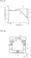
- Fig. 27 is a diagram showing an attenuated sound compensation process by the reverberation time control unit 34 according to Embodiment 1.
- the horizontal axis represents frequency
- the vertical axis represents sound pressure level.
- the arrow C indicates the increment of sound pressure level attributed to the equalizer process. This makes it possible to reproduce an attenuated sound component of the waveform 68 to give a waveform 69.
- the audio system 13 according to Embodiment 1 conducts time-lapse radiation of cross sounds and direct sounds, angle-by-angle and frequency-by-frequency phase control, and reverberation time control. This makes it possible to control the feeling of sound spreading inside the car 5 and give a passenger the illusion that the small space inside the car 5 is a larger indoor space.
- the audio system 13 according to Embodiment 1 makes it possible to, while having a reduced number of speaker units, form a stereoscopic sound field environment throughout the inside of the car 5 and thereby bring about improvement in sound quality. This results in making it possible to create a reverberant sound environment, such as a church or a stadium, that is often used as a large indoor space.
- two speaker units 23 are located on either side as a basic configuration. This causes sound to be radiated from either side of a passenger, thus allowing the passenger to feel a more natural sound field.
- the audio system 13 creates a stereoscopic sound field environment. This allows a passenger to enjoy a realistic feeling of being in a large space while being in the small space inside the car 5. Embodiment 1 allows the passenger to auditorily feel space spreading at the same time as the passenger gets on the car 5. This makes it possible to reduce the stress of riding with a stranger in a small space inside the car 5.
- a plurality of speaker units 23 may be mounted in one speaker cabinet 20.
- a frequency band of sounds that are radiated by one speaker unit 23 can be made different from a frequency band of sounds that are radiated by another speaker unit 23, so that various frequency bands can be finely radiated. This results in making it possible to cover a wide frequency band with one speaker cabinet 20. This makes it possible to easily further improve the sound quality of the audio system 13.
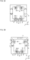
- Fig. 28 is a top view showing a configuration of an audio system 13 according to Embodiment 2.
- a front view of the audio system 13 refer to Fig. 3 , as the front view is basically the same as that of Fig. 3 .
- FIG. 28 A comparison between Fig. 4 and Fig. 28 shows that in Fig. 28 , the speaker units 23R and 23L are located closer to the back than the central portion in the Z direction (i.e. the direction parallel with the depth of the car 5).
- a side of the inside of the car 5 in which the car door 5d is provided is herein referred to as "front side”
- a side of the inside of the car 5 facing the front side is herein referred to as "back side”.
- the radiation surfaces 23a of the speaker units 23 are disposed to face the right and left side boards 5a of the car 5, as in the case of Embodiment 1. That is, each of the radiation surfaces 23a is disposed to face the gap 11. Further, the radiation surface 23a is located along a side of a side surface 10a of the suspended ceiling 10. Accordingly, the position of the radiation surface 23a in the X direction (i.e. the direction parallel with the width of the car 5) agrees or substantially agrees with the position of the side surface 10a of the suspended ceiling 10 in the X direction. Thus, the radiation surface 23a is located in the same plane as the side surface 10a of the suspended ceiling 10.
- the audio system 13 according to Embodiment 2 brings about effects similar to those brought about by that of Embodiment 1, as the audio system 13 according to Embodiment 2 is basically similar in configuration to that of Embodiment 1.
- Fig. 29 is a top view showing a configuration of an audio system 13 according to Embodiment 3.
- a front view of the audio system 13 refer to Fig. 3 , as the front view is basically the same as that of Fig. 3 .
- FIG. 29 A comparison between Fig. 4 and Fig. 29 shows that in Fig. 29 , four speaker units 23R-1, 23R-2, 23L-1, and 23L-2 are provided.
- the speaker units 23R-1 and 23L-1 are located closer to the back than the central portion in the Z direction.
- the speaker units 23R-2 and 23L-2 are located closer to the front than the central portion in the Z direction.
- the speaker units 23R-1 and the speaker unit 23R-2 are placed at a constant second distance D2 from each other, centering around the central portion of the suspended ceiling 10 in the Z direction.
- the speaker units 23L-1 and the speaker unit 23L-2 are placed at the constant second distance D2 from each other, centering around the central portion of the suspended ceiling 10 in the Z direction.
- the second distance D2 is the distance between speaker units 23, this case is not intended to impose any limitation.
- the second distance D2 may be the distance between the casings 25 of speaker cabinets 20.
- the radiation surfaces 23a of the speaker units 23 are disposed to face the right and left side boards 5a of the car 5, as in the case of Embodiment 1. Further, each of the radiation surfaces 23a is located along a side of a side surface 10a of the suspended ceiling 10. Accordingly, the position of the radiation surface 23a in the X direction (i.e. the direction parallel with the width of the car 5) agrees or substantially agrees with the position of the side surface 10a of the suspended ceiling 10 in the X direction.
- Embodiment 1 there is a gap 11 of the first distance D between a side board of the suspended ceiling 10 and a side board 5a of the car 5.
- the sound radiated from the four speaker units 23 is radiated in the directions of arrows A from the radiation surfaces 23a.
- the sound is reflected off the side boards 5a of the car 5 to turn into reflected sound that is radiated to the inside of the car 5.
- "indirect sound radiation” is conducted by which sound is radiated from the suspended ceiling 10 to a passenger through the use of reflection off the side boards 5a of the car 5, as in the case of Embodiment 1.
- the audio system 13 according to Embodiment 3 brings about effects similar to those brought about by that of Embodiment 1, as the audio system 13 according to Embodiment 3 is basically similar in configuration to that of Embodiment 1. Further, according to Embodiment 3, the number of speaker units 23 is larger than in Embodiment 1. This makes it possible to form a more stereoscopic sound field environment with higher sound quality, thus making it possible to more noticeably experience a pseudo-large space.
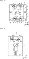
- Fig. 30 is a front view showing a configuration of an audio system 13 according to Embodiment 4.
- Fig. 31 is a top view showing the configuration of the audio system 13 according to Embodiment 4.
- FIG. 31 A comparison between Fig. 4 and Fig. 31 shows that in Fig. 31 , four speaker units 23R-1, 23R-2, 23L-1, and 23L-2 are provided. Further, in Fig. 4 described above, the speaker units 23 are placed opposite the right and left side boards 5a of the car 5. However, in Fig. 31 , the four speaker units 23R-1, 23R-2, 23L-1, and 23L-2 are placed opposite the front and back side boards 5a of the car 5.
- Two speaker units 23R-1 and 23L-1 are placed opposite the back side board 5a of the car 5.
- the speaker units 23R-1 and the speaker unit 23L-1 are placed at a constant distance from each other, centering around the central portion of the suspended ceiling 10 in the X direction.
- the constant distance may for example be equal to the second distance D2 shown in Fig. 29 .
- the other speaker units 23R-2 and 23L-2 are placed opposite the front side board 5a of the car 5. Accordingly, as shown in Fig. 30 , the radiation surfaces 23a of the speaker units 23R-2 and 23L-2 are disposed in a direction toward the car door 5d.
- the speaker units 23R-2 and the speaker unit 23L-2 are placed at a constant distance from each other, centering around the central portion of the suspended ceiling 10 in the X direction.
- the constant distance may for example be equal to the second distance D2 shown in Fig. 29 .
- each of the radiation surfaces 23a of the speaker units 23 is disposed to face a corresponding one of the side boards 5a of the car 5, as in the case of Embodiment 1. Further, each of the radiation surfaces 23a is located along a side of a side surface 10a of the suspended ceiling 10. Accordingly, the position of the radiation surface 23a in the Z direction (i.e. the direction parallel with the depth of the car 5) agrees or substantially agrees with the position of the side surface 10a of the suspended ceiling 10 in the Z direction.
- the audio system 13 according to Embodiment 4 brings about effects similar to those brought about by that of Embodiment 1, as the audio system 13 according to Embodiment 4 is basically similar in configuration to that of Embodiment 1. Further, according to Embodiment 4, the number of speaker units 23 is larger than in Embodiment 1. This makes it possible to form a more stereoscopic sound field environment with higher sound quality, thus making it possible to more noticeably experience a pseudo-large space.
- Fig. 32 is a front view schematically showing a configuration of an audio system 13 according to Embodiment 5.
- Fig. 33 is a top view showing the configuration of the audio system 13 according to Embodiment 5.
- FIG. 33 four speaker units 23R-1, 23R-2, 23L-1, and 23L-2 are provided.
- two of the four speaker units 23R-1, 23R-2, 23L-1, and 23L-2 namely the speaker units 23R-2 and 23L-2, are placed opposite the front side board 5a of the car 5.
- the other two speaker units 23R-1 and 23L-1 are provided opposite the floor board 5b of the car 5. Accordingly, the radiation surfaces 23a of the speaker units 23R-1 and 23L-1 are disposed to face the floor board 5b of the car 5 as shown in Fig. 32 .
- the two front speaker units 23R-2 and 23L-2 are placed opposite the front side board 5a of the car 5.
- the speaker units 23R-2 and the speaker unit 23L-2 are placed at a constant distance from each other, centering around the central portion of the suspended ceiling 10 in the X direction.
- the constant distance may for example be equal to the second distance D2 shown in Fig. 29 .
- each of the radiation surfaces 23a of the speaker units 23R-2 and 23L-2 is disposed to face a corresponding one of the side boards 5a of the car 5. Further, each of the radiation surfaces 23a is located along a side of a side surface 10a of the suspended ceiling 10. Accordingly, the position of each of the radiation surfaces 23a in the Z direction (i.e. the direction parallel with the depth of the car 5) agrees or substantially agrees with the position of a corresponding one of the side surfaces 10a of the suspended ceiling 10 in the Z direction.
- the two back speaker units 23R-1 and 23L-1 are placed opposite the floor board 5b of the car 5. Accordingly, as mentioned above, the radiation surfaces 23a of the speaker units 23R-1 and 23L-1 are disposed to face the floor board 5b of the car 5 as shown in Fig. 32 .
- the speaker units 23R-1 and the speaker unit 23L-1 are placed at a constant distance from each other, centering around the central portion of the suspended ceiling 10 in the X direction.
- the constant distance may for example be equal to the second distance D2 shown in Fig. 29 .
- each of the radiation surfaces 23a of the speaker units 23R-1 and 23L-1 is located in the same plane as the lower surface 10b of the suspended ceiling 10. Accordingly, the position of each of the radiation surfaces 23a in the Y direction (i.e. the direction parallel with the height of the car 5) agrees or substantially agrees with the position of the lower surface 10b of the suspended ceiling 10 in the Y direction. Further, the radiation surfaces 23a of the speaker units 23R-1 and 23L-1 are fitted in mounting holes provided in the lower surface 10b of the suspended ceiling 10. Each of the radiation surfaces 23a of the speaker units 23R-1 and 23L-1 is exposed to the outside through a corresponding one of the mounting holes. Accordingly, sound radiated from each of the radiation surfaces 23a of the speaker units 23R-1 and 23L-1 is not insulated by the lower surface 10b of the suspended ceiling 10.
- the sound radiated from the speaker units 23R-1 and 23L-1 is radiated in the directions of arrows A from the radiation surfaces 23a.
- the speaker units 23R-1 and 23L-1 conduct "direct sound radiation" by which the speaker units 23R-1 and 23L-1 radiate sound from the suspended ceiling 10 directly to a passenger.
- the audio system 13 according to Embodiment 5 brings about effects similar to those brought about by that of Embodiment 1, as the audio system 13 according to Embodiment 5 is basically similar in configuration to that of Embodiment 1. Further, according to Embodiment 5, the number of speaker units 23 is larger than in Embodiment 1. This makes it possible to form a more stereoscopic sound field environment with higher sound quality, thus making it possible to more noticeably experience a pseudo-large space. According to Embodiment 5, both "indirect sound radiation” and “direct sound radiation” are conducted. This makes it possible to form a stereoscopic sound field environment with high sound quality.
- Fig. 34 is a top view showing a configuration of an audio system 13 according to Embodiment 6.
- a front view of the audio system 13 refer to Fig. 30 , as the front view is basically the same as that of Fig. 30 .
- Fig. 34 four speaker units 23R-1, 23R-2, 23L-1, and 23L-2 are provided.
- the two back speaker units 23R-1 and 23L-1 are placed opposite the right and left side boards 5a of the car 5. Accordingly, the speaker units 23R-1 and 23L-1 have their back surfaces facing each other. The speaker units 23R-1 and 23L-1 are located closer to the back than the central portion in the Z direction.
- the two front speaker units 23R-2 and 23L-2 are placed opposite the front side board 5a of the car 5.
- the speaker units 23R-2 and 23L-2 are placed at a constant distance from each other, centering around the central portion of the suspended ceiling 10 in the X direction.
- the constant distance may for example be equal to the second distance D2 shown in Fig. 29 .
- each of the radiation surfaces 23a of the speaker units 23 is disposed to face a corresponding one of the side boards 5a of the car 5, as in the case of Embodiment 1. Further, each of the radiation surfaces 23a is located along a side of a side surface 10a of the suspended ceiling 10. Accordingly, each of the radiation surface 23a is located in the same plane as a corresponding one of the side surfaces 10a of the suspended ceiling 10.
- the audio system 13 according to Embodiment 6 brings about effects similar to those brought about by that of Embodiment 1, as the audio system 13 according to Embodiment 6 is basically similar in configuration to that of Embodiment 1. Further, according to Embodiment 6, the number of speaker units 23 is larger than in Embodiment 1. This makes it possible to form a more stereoscopic sound field environment with higher sound quality, thus making it possible to more noticeably experience a pseudo-large space.
- Fig. 35 is a front view showing a configuration of an audio system 13 according to Embodiment 7.
- the lighting device 5e is provided inside the suspended ceiling 10.
- the lighting device 5e is formed of a blue-sky illuminator.
- the blue-sky illuminator reproduces the color of a clear blue sky on a sunny day, for example, through a combination of blue LEDs and white LEDs. Accordingly, installing the blue-sky illuminator makes it possible to provide a passenger with a realistic feeling of having a skylight on the ceiling of the car 5.
- Fig. 36 is a cross-sectional view showing a configuration of the lighting device 5e according to Embodiment 7.
- blue LEDs 76 and white LEDs 77 are provided inside a housing 75.
- a light-guiding plate 73 is provided between the two blue LEDs 76, which face each other.
- the blue LEDs 76 and the light-guiding plate 73 form a blue-sky panel.
- the light-guiding plate 73 includes a light scatterer inside. Light emitted from the blue LEDs 76 enter the light-guiding plate 73 through ends of the light-guiding plate 73. The light travels through the inside of the light-guiding plate 73 while being totally reflected by upper and lower surfaces of the light-guiding plate 73.
- the light scatterer causes Rayleigh scattering to be simulated.
- Rayleigh scattering is a phenomenon that, when sunlight enters the atmosphere, occurs due to molecules forming the atmospheric air.
- the light scattered by the light scatterer turns into blue light that is emitted downward from an emission surface 73a of the light-guiding plate 73. This causes blue sky to be reproduced.
- light emitted from the white LEDs 77 is emitted from a light-emitting surface 74 provided in a frame. This causes natural light coming through the skylight to be expressed.
- the lighting device 5e is a blue-sky illuminator
- blue sky and natural light can be expressed with a sense of depth inside the car 5 by a low-profile blue-sky panel and a frame configured to express sunlight streaming.
- the audio system 13 according to Embodiment 7 brings about effects similar to those brought about by that of Embodiment 1, as the audio system 13 according to Embodiment 7 is basically similar in configuration to that of Embodiment 1.
- the lighting device 5e is formed of a blue-sky illuminator. This allows a passenger inside the car 5 to auditorily and visually experience a pseudo-large space.
Landscapes
- Engineering & Computer Science (AREA)
- Health & Medical Sciences (AREA)
- Otolaryngology (AREA)
- Physics & Mathematics (AREA)
- Acoustics & Sound (AREA)
- Signal Processing (AREA)
- Multimedia (AREA)
- Civil Engineering (AREA)
- Mechanical Engineering (AREA)
- Structural Engineering (AREA)
- Cage And Drive Apparatuses For Elevators (AREA)
- Indicating And Signalling Devices For Elevators (AREA)
- Stereophonic System (AREA)
Abstract
Description
- The present disclosure relates to an audio system for an elevator configured to radiate sound to the inside of a car of the elevator.
- In a car of a related-art elevator, a speaker configured to provide a passenger inside the car with voice guidance is installed. Further, an intercom configured for a passenger to, in case of emergency, speak to a person outside the car is installed inside the car. In general, such a speaker and such an intercom are installed in a car operation panel.
- Further, for example,
Patent Literature 1 discloses an elevator configured to send out BGM (background music) as well as voice guidance to the inside of a car. This elevator has provided inside a car thereof a speaker and a BGM reproduction device configured to reproduce BGM. - Further,
Patent Literature 2 discloses an elevator having a plurality of speakers placed at regular intervals in a vertically linear fashion. This elevator is configured such that in a case in which a car travels upward, audio signals are outputted in sequence to a speaker installed at the uppermost position first and then to a speaker installed at the lowermost position. This gives a passenger the feeling that an audio signal has moved downward. By thus switching in sequence from outputting an audio signal to one speaker to outputting an audio signal to another speaker, this elevator can give a passenger the feeling that the elevator is ascending or descending. -
- Patent Literature 1:
Japanese Unexamined Patent Application Publication No. 2009-35340 - Patent Literature 2:
Japanese Patent No. 5322607 - The elevator disclosed in
Patent Literature 1 has one speaker installed inside the car. The elevator disclosed inPatent Literature 2 has a plurality of speakers vertically arranged side by side. - However, in the elevators disclosed in
Patent Literatures - Further, the elevators disclosed in
Patent Literatures - Further,
Patent Literature 2 is undesirably expensive, as the number of speakers is large. - The present disclosure has been made to solve such problems and an object thereof is to provide an audio system for an elevator configured to, while having a reduced number of speaker units, form a stereoscopic sound field environment throughout the inside of a car and thereby bring about improvement in sound quality. Solution to Problem
- An audio system for an elevator according to an embodiment of the present disclosure includes two or more speaker cabinets arranged inside a suspended ceiling fixed to a ceiling board of a car of the elevator, an input device to which sound content radiated to an inside of the car from each of the two or more speaker cabinets are input, and a sound field control device configured to conduct a control as phase control and reverberation time control for the sound content and thereby cause a sound wave based on the sound content to be radiated from the speaker cabinet to the inside of the car. Each of the speaker cabinets includes a casing arranged inside the suspended ceiling, and a speaker unit arranged inside the casing and having a radiation surface that radiates the sound wave.
- The audio system for an elevator according to the embodiment of the present disclosure makes it possible to, while having a reduced number of speaker units, form a stereoscopic sound field environment throughout the inside of a car and thereby bring about improvement in sound quality.
-
- [
Fig. 1] Fig. 1 is a perspective view showing a configuration of anelevator 1 according toEmbodiment 1. - [
Fig. 2] Fig. 2 is a diagram showing an internal appearance of acar 5 of theelevator 1 according toEmbodiment 1. - [
Fig. 3] Fig. 3 is a front view showing a configuration of anaudio system 13 according toEmbodiment 1. - [
Fig. 4] Fig. 4 is a top view showing an arrangement ofspeaker cabinets 20 of theaudio system 13 according to Embodiment 1. - [
Fig. 5] Fig. 5 is a side view showing a configuration of an example of aspeaker cabinet 20 according toEmbodiment 1. - [
Fig. 6] Fig. 6 is a front view of thespeaker cabinet 20 ofFig. 5 . - [
Fig. 7] Fig. 7 is a side view showing a configuration of another example of aspeaker cabinet 20 according toEmbodiment 1. - [
Fig. 8] Fig. 8 is a front view of thespeaker cabinet 20 ofFig. 7 . - [
Fig. 9] Fig. 9 is a block diagram showing a configuration of a soundfield control device 21 according toEmbodiment 1. - [
Fig. 10] Fig. 10 is a top view showing a model of a relationship betweenspeaker units 23 andmicrophones 40 in theaudio system 13 according to Embodiment 1. - [
Fig. 11] Fig. 11 is a diagram showing the waveforms of direct sounds and cross sounds according toEmbodiment 1. - [
Fig. 12] Fig. 12 is a top view showing a model of a relationship between thespeaker units 23 and themicrophones 40. - [
Fig. 13] Fig. 13 is a diagram showing the waveforms of sound waves outputted from a propagationcharacteristic control unit 31 provided in theaudio system 13 according toEmbodiment 1. - [
Fig. 14] Fig. 14 is a model diagram showing a case in which twospeaker units - [
Fig. 15] Fig. 15 is a model diagram showing a sound radiation pattern of asynthetic sound pressure 72 formed of the twospeaker units - [
Fig. 16] Fig. 16 is a diagram showing a state in which test sound is sent out by adirectivity control unit 32 provided in theaudio system 13 according toEmbodiment 1. - [
Fig. 17] Fig. 17 is a diagram showing phase signals of a first directivity angle P before and after control by thedirectivity control unit 32 according toEmbodiment 1. - [
Fig. 18] Fig. 18 is a diagram showing phase signals of a second directivity angle Q before and after control by thedirectivity control unit 32 according toEmbodiment 1. - [
Fig. 19] Fig. 19 is a diagram showing an example of a configuration of thedirectivity control unit 32 according toEmbodiment 1. - [
Fig. 20] Fig. 20 is a diagram showing the waveforms of sounds received by amicrophone Embodiment 1. - [
Fig. 21] Fig. 21 is a diagram showing waveforms outputted from adelay control unit 33 according toEmbodiment 1. - [
Fig. 22] Fig. 22 is a diagram showing the waveform of a sound as measured by themicrophones 40 in the case of specification A according toEmbodiment 1. - [
Fig. 23] Fig. 23 is a diagram showing the waveform of a sound outputted from a reverberationtime control unit 34 according toEmbodiment 1. - [
Fig. 24] Fig. 24 is a diagram showing the waveform of a sound as measured by themicrophones 40 in the case of specification B according toEmbodiment 1. - [
Fig. 25] Fig. 25 is a diagram showing the waveform of a sound as measured by themicrophones 40 in the case of specification C according toEmbodiment 1. - [
Fig. 26] Fig. 26 is a diagram showing a state in which test sound is sent out by the reverberationtime control unit 34 provided in theaudio system 13 according toEmbodiment 1. - [
Fig. 27] Fig. 27 is a diagram showing an attenuated sound compensation process by the reverberationtime control unit 34 according toEmbodiment 1. - [
Fig. 28] Fig. 28 is a top view showing a configuration of anaudio system 13 according to Embodiment 2. - [
Fig. 29] Fig. 29 is a top view showing a configuration of anaudio system 13 according to Embodiment 3. - [
Fig. 30] Fig. 30 is a front view showing a configuration of anaudio system 13 according to Embodiment 4. - [
Fig. 31] Fig. 31 is a top view showing the configuration of theaudio system 13 according to Embodiment 4. - [
Fig. 32] Fig. 32 is a front view schematically showing a configuration of anaudio system 13 according toEmbodiment 5. - [
Fig. 33] Fig. 33 is a top view showing the configuration of theaudio system 13 according to Embodiment 5. - [
Fig. 34] Fig. 34 is a top view showing a configuration of anaudio system 13 according toEmbodiment 6. - [
Fig. 35] Fig. 35 is a front view showing a configuration of anaudio system 13 according toEmbodiment 7. - [
Fig. 36] Fig. 36 is a cross-sectional view showing a configuration of alighting device 5e according toEmbodiment 7. - In the following, audio systems for an elevator according to embodiments of the present disclosure are described with reference to the drawings. The present disclosure is not limited to the following embodiments, but may be modified in various ways, provided such modifications do not depart from the scope of the present disclosure. Further, the present disclosure encompasses all combinations of combinable components of components of the following embodiments and modifications thereof. Further, components given identical signs in the drawings are identical or equivalent to each other, and these signs are adhered to throughout the full text of the description. In the drawings, relative relationships in dimension between components, the shapes of the components, or other features of the components may be different from actual ones.
-
Fig. 1 is a perspective view showing a configuration of anelevator 1 according toEmbodiment 1. As shown inFig. 1 , theelevator 1 is installed inside a building and configured to ascend or descend through the inside of ahoistway 2. In an upper part of thehoistway 2, a hoistingmachine 3 is provided. The hoistingmachine 3 is provided with asheave 3a. Over thesheave 3a, amain rope 4 is stretched. Themain rope 4 has two ends coupled to acar 5 and a balancingweight 6, respectively. Thecar 5 and the balancingweight 6 are reversibly suspended from thesheave 3a by themain rope 4. Further, in the upper part of thehoistway 2, anelevator control panel 7 is installed. Theelevator control panel 7 is connected to the hoistingmachine 3 via a communication line and connected to thecar 5 via acontrol cable 8. Thecontrol cable 8 transmits electricity and control signals to thecar 5. Thecontrol cable 8 is also referred to as "tail cord". - The
car 5 is formed of fourside boards 5a, afloor board 5b, and a ceiling board 5c. The fourside boards 5a are located on the right, left, front, and back sides, respectively, of thecar 5. Further, in thefront side board 5a of the fourside boards 5a, acar door 5d is installed. Each time thecar 5 stops at an elevator hall on a floor of the building, thecar door 5d conducts opening and closing operations in engagement with an elevator hall door (not illustrated) installed in the elevator hall. - On an upper surface of the ceiling board 5c of the
car 5, as shown inFig. 1 , acar control device 9 is installed. Thecar control device 9 conducts control of operation of devices provided in thecar 5. Examples of the devices provided in thecar 5 include thecar door 5d, alighting device 5e (seeFig. 2 ), acar operation panel 5f (seeFig. 2 ), and anaudio system 13 for an elevator (seeFig. 3 ). Theaudio system 13 for an elevator is hereinafter simply referred to as "audio system 13". - To a lower surface of the ceiling board 5c of the
car 5, as shown inFig. 1 , a suspendedceiling 10 is fixed. The suspendedceiling 10 has a cuboidal shape. The suspendedceiling 10 has fourside surfaces 10a and alower surface 10b (seeFig. 2 ). Further, the suspendedceiling 10 may further have an upper surface disposed to face thelower surface 10b. In an internal space of the suspendedceiling 10, thelighting device 5e (seeFig. 2 ) and the audio system 13 (seeFig. 3 ) are installed. Between the side surfaces 10a of the suspendedceiling 10 and theside boards 5a of thecar 5, there is agap 11 of a constant distance D (seeFigs. 2 and3 ). The constant distance D is hereinafter referred to as "first distance D". - Although the example shown in
Fig. 1 illustrates a case in which theelevator 1 is a rope elevator, this case is not intended to impose any limitation. Theelevator 1 may for example be another type of elevator such as a maglev elevator. -
Fig. 2 is a diagram showing an internal appearance of thecar 5 of theelevator 1 according toEmbodiment 1. As shown inFig. 2 , an internal space of thecar 5 is surrounded by theside boards 5a, thefloor board 5b, and thelower surface 10b of the suspendedceiling 10. The internal space of thecar 5 is for example in the shape of a cuboid. Thefloor board 5b is formed of a flat surface placed in a horizontal direction. Theside boards 5a are formed of flat surfaces placed in a perpendicular direction. The term "perpendicular direction" here means, for example, a vertical direction. Thelower surface 10b of the suspendedceiling 10 is disposed to face thefloor board 5b. The suspendedceiling 10 is provided with thelighting device 5e. Thelighting device 5e has its body installed in the internal space of the suspendedceiling 10. Thelighting device 5e is for example an LED lighting device. As shown inFig. 2 , thelighting device 5e has an illumination surface 5ea facing thefloor board 5b. Thelighting device 5e illuminates the internal space of thecar 5 with light shone from the illumination surface 5ea. - As mentioned above, the
front side board 5a of the fourside boards 5a is provided with thecar door 5d. Further, as shown inFig. 2 , thefront side board 5a is provided with thecar operation panel 5f. Thecar operation panel 5f is provided with a plurality of car call registration buttons provided separately in correspondence with each floor and door opening and closing buttons configured to control opening and closing operations of thecar door 5d. Furthermore, thecar operation panel 5f is provided with anintercom device 5h configured for a passenger to have outside communications in case of emergency. In addition to being used to have outside communications, theintercom device 5h may also be used to send out a voice message such as "THE DOOR WILL CLOSE" to a passenger. - As shown in
Fig. 2 , thecar control device 9 is connected to theelevator control panel 7, for example, via the control cable 8 (seeFig. 1 ). As shown inFig. 2 , thecar control device 9 includes aninput unit 9a, acontrol unit 9b, anoutput unit 9c, a soundfield control unit 9d, and astorage unit 9e. Theinput unit 9a inputs control signals from theelevator control panel 7 to thecontrol unit 9b. Based on these control signals, thecontrol unit 9b conducts control of operation of the devices provided in thecar 5. Under control of thecontrol unit 9b, theoutput unit 9c outputs driving signals separately to each of the devices. Further, under control of thecontrol unit 9b, theoutput unit 9c transmits, to theelevator control panel 7, a signal of, for example, car call registration inputted from a passenger to thecar operation panel 5f. The soundfield control unit 9d is one of the constituent elements of theaudio system 13. The soundfield control unit 9d controls the operation of theaudio system 13 to form a stereoscopic sound field with high sound quality throughout the internal space of thecar 5. Theoutput unit 9c and the soundfield control unit 9d form the after-mentioned soundfield control device 21. - A hardware configuration of the
car control device 9 is described here. Functions of theinput unit 9a, thecontrol unit 9b, theoutput unit 9c, and the soundfield control unit 9d in thecar control device 9 are implemented by a processing circuit. The processing circuit is formed of dedicated hardware or a processor. The dedicated hardware is for example an ASIC (application specific integrated circuit), an FPGA (Field Programmable Gate Array), or other hardware. The processor executes a program stored in a memory. Thestorage unit 9e is formed of the memory. The memory is a nonvolatile or volatile semiconductor memory such as a RAM (random-access memory), a ROM (read-only memory), a flash memory, or an EPROM (erasable programmable ROM) or a disc such as a magnetic disc, a flexible disc, or an optical disc. -
Fig. 3 is a front view showing a configuration of theaudio system 13 according toEmbodiment 1.Fig. 4 is a top view showing an arrangement ofspeaker cabinets 20 of theaudio system 13 according toEmbodiment 1. Let it be assumed inFigs. 3 and4 that a direction parallel with the height of thecar 5 is a Y direction, that a direction parallel with the width of thecar 5 is an X direction, and that a direction parallel with the depth of thecar 5 is a Z direction. The Y direction is for example a vertical direction. Further, as shown inFig. 4 , the right, left, front, and back of the inside of thecar 5 are defined such that the X direction is a direction from side to side of thecar 5 and the Z direction is a direction toward both the front and back of thecar 5. - As shown in
Figs. 3 and4 , theaudio system 13 is formed of one ormore speaker cabinets 20, a soundfield control device 21, and aninput device 22. Theaudio system 13 radiates sound to a passenger in thecar 5.Embodiment 1 uses, as the sound, sound content, such as the murmur of a river or the chirping of a bird, that calls up an image of nature is used as the sound. - According to
Embodiment 1, as shown inFig. 3 , the number ofspeaker cabinets 20 is 2. However, the number ofspeaker cabinets 20 is not limited to this number but may be any number larger than or equal to 1. As shown inFig. 3 , each of thespeaker cabinets 20 is installed the internal space of the suspendedceiling 10. Each of thespeaker cabinets 20 is formed of aspeaker unit 23 and acasing 25. -
Fig. 5 is a side view showing a configuration of an example of aspeaker cabinet 20 according toEmbodiment 1.Fig. 6 is a front view of thespeaker cabinet 20 ofFig. 5 . As shown inFigs. 5 and 6 , thespeaker unit 23 is accommodated in thecasing 25. Thespeaker unit 23 has provided on afront surface 25a of thecasing 25 aradiation surface 23a that radiates sound. Thecasing 25 has, for example, a cuboidal shape. Thecasing 25 is a closed apparatus. Theradiation surface 23a of thespeaker unit 23 is exposed outward through an installation hole provided in thecasing 25. Other parts of thespeaker unit 23 are all installed inside thecasing 25. Accordingly, the sound from theradiation surface 23a of thespeaker unit 23 is radiated only in the direction of an arrow A inFig. 5 , and is not radiated outward via the other parts of thecasing 25 other than theradiation surface 23a. -
Fig. 7 is a side view showing a configuration of another example of aspeaker cabinet 20 according toEmbodiment 1.Fig. 8 is a front view of thespeaker cabinet 20 ofFig. 7 . As shown inFigs. 7 and 8 , thespeaker cabinet 20 may have two ormore speaker units 23 accommodated inside thecasing 25. In this case, for example, one speaker unit 23-1 may be a full-range speaker, and the other speaker unit 23-2 may be a tweeter. The term "full-range speaker" means a speaker configured to reproduce a low-to-high range with one speaker. In each of the embodiments of the present disclosure, onespeaker unit 23 accommodated inside thecasing 25 of aspeaker cabinet 20 is a full-range speaker. Further, the term "tweeter" means a speaker dedicated to a low range for use as an aid to a full-range speaker. It is difficult to reproduce a low-to-high range with one speaker, and doing so may result in poor sound quality. In such a case, a tweeter is used to compensate for the poor sound quality. Thus, the two ormore speaker units 23 arranged inside thecasing 25 may be of different types or may be of the same type. In such a case in which onespeaker cabinet 20 includes a plurality ofspeaker units 23, a feeling of sound quality can be improved and a wider band can be reproduced with thespeaker cabinet 20 alone. - Continued reference is made to
Figs. 3 and4 . As shown inFigs. 3 and4 , thespeaker cabinets 20 are arranged in the internal space of the suspendedceiling 10. The height of the suspendedceiling 10 in the Y direction (i.e. the direction parallel with the height of the car 5) is approximately 5 cm. Accordingly, as shown inFig. 3 , the height H1 of thecasing 25 of each of thespeaker cabinets 20 in the Y direction (i.e. the direction parallel with the height of the car 5) is less than or equal to 5 cm. Further, theradiation surface 23a of thespeaker unit 23 is disposed to face aside board 5a of thecar 5. Theradiation surface 23a is located along an edge of aside surface 10a of the suspendedceiling 10. Theradiation surface 23a is located in the same plane as theside surface 10a of the suspendedceiling 10. Accordingly, the position of theradiation surface 23a in the X direction (i.e. the direction parallel with the width of the car 5) agrees or substantially agrees with the position of theside surface 10a of the suspendedceiling 10 in the X direction. Theside surface 10a of the suspendedceiling 10 is provided with an opening in alignment with the position of theradiation surface 23a. It should be noted that theside surface 10a of the suspendedceiling 10 may be entirely in an open state. Accordingly, the sound radiated from theradiation surface 23a is not insulated by theside surface 10a of the suspendedceiling 10. Further, as mentioned above, there is agap 11 of the first distance D between theside surface 10a of the suspendedceiling 10 and theside board 5a of thecar 5. The first distance D is approximately 5 cm. As shown inFigs. 3 and4 , the sound radiated from theradiation surface 23a of thespeaker unit 23 is radiated in the direction of an arrow A. After that, the sound is reflected off theside board 5a of thecar 5 to turn into reflected sound. As shown inFigs. 3 and4 , the reflected sound travels in the directions of arrows B. Thus, according toEmbodiment 1, thespeaker unit 23 conducts "indirect sound radiation" by which thespeaker unit 23 radiates sound to a passenger through the use of reflection off theside board 5a of thecar 5. - Further, as shown in
Fig. 4 , each of thespeaker cabinets 20 is located in a central portion of the suspendedceiling 10 in the Z direction (i.e. the direction parallel with the depth of the car 5). Further, as shown inFig. 3 , each of thespeaker cabinets 20 is located in a central portion of the suspendedceiling 10 in the Y direction (i.e. the direction parallel with the height of the car 5). - The
speaker unit 23 provided in one of the twospeaker cabinets 20 shown inFig. 4 is referred to as "speaker unit 23R". Further, thespeaker unit 23 provided in thespeaker cabinet 20 is referred to as "speaker unit 23L". Thespeaker unit 23R and thespeaker unit 23L are placed at a clearance from each other. Thespeaker unit 23R and thespeaker unit 23L are arranged so that their respective back surfaces face each other. When described with reference to apassenger model 42 shown inFig. 4 , theradiation surface 23a of thespeaker unit 23R is disposed to face theright side board 5a of thecar 5. Meanwhile, theradiation surface 23a of thespeaker unit 23L is disposed to face theleft side board 5a of thecar 5. Each of the radiation surfaces 23a of thespeaker units gap 11. Each of the radiation surfaces 23a of thespeaker units ceiling 10. - According to
Embodiment 1, each of thespeaker units 23 reproduces sound pressures lying within a frequency band ranging, for example, from 150 Hz to 48 kHz. That is, sound of a low frequency lower than 150 Hz is not used. A reason for this is explained. The inside of thecar 5 is an enclosed space. Therefore, a low-frequency component of a long wavelength is reflected more than once among theside boards 5a of the inside of thecar 5. This results in a long reflection time, a persistent standing wave, and a long reverberation time. A standing wave generated by the reflection of sound is hereinafter referred to as "echo". Thus, it is harder for a low-frequency sound to become attenuated inside thecar 5 than sound radiated in an open space. This results in a low-frequency sound persistently echoing inside thecar 5 to cause a passenger unnecessary low-frequency noise that gives the passenger a feeling of unwanted discomfort. Accordingly,Embodiment 1 is required to reproduce a band of frequencies higher than or equal to 150 Hz. This makes it possible to avoid giving the passenger a feeling of discomfort and give the passenger comfort. Further, as for a high-frequency component, a frequency band compatible with 96 kHz/24 bit is rendered reproducible for the purpose of providing high sound quality with high resolution based on a high-resolution sound source.Embodiment 1 assumes a band of frequencies lower than or equal to 48 kHz, which is half as high as 96 kHz/24 bit. - Continued reference is made to
Fig. 3 . The soundfield control device 21 is located inside thecar control device 9 provided on the upper surface of the ceiling board 5c of thecar 5. As shown inFig. 2 , the soundfield control device 21 includes theoutput unit 9c and the soundfield control unit 9d. Further, the soundfield control device 21 further includes a power source (not illustrated). The soundfield control unit 9d is provided with a sound field control substrate. -
Fig. 9 is a block diagram showing a configuration of the soundfield control device 21 according toEmbodiment 1. As mentioned above, the soundfield control device 21 includes theoutput unit 9c and the soundfield control unit 9d. - The
output unit 9c includes a D/A converter 36 and anamplifier 37. The D/A converter 36 converts a digital signal into an analog signal and outputs the analog signal. Theamplifier 37 amplifies the analog signal outputted from the D/A converter 36. The analog signal outputted from theamplifier 37 is transmitted to each of thespeaker units 23. Thespeaker unit 23 radiates the analog signal as sound from theradiation surface 23a. - The sound
field control unit 9d includes an A/D converter 30, a propagationcharacteristic control unit 31, adirectivity control unit 32, adelay control unit 33, a reverberationtime control unit 34, a synthesizingunit 35, and astorage device 39. Thestorage device 39 may be part of thestorage unit 9e shown inFig. 2 , or may be formed of another memory. - The A/
D converter 30 is supplied with aninput signal 38 inputted from theinput device 22. Theinput signal 38 is an analog signal. Theinput signal 38 is the aforementioned sound content. The A/D converter 30 converts the analog signal into a digital signal and outputs the digital signal. The digital signal outputted from the A/D converter 30 is inputted to the propagationcharacteristic control unit 31, thedirectivity control unit 32, thedelay control unit 33, and the reverberationtime control unit 34. - The propagation
characteristic control unit 31 conducts time-axis crosstalk phase component control on the digital signal outputted from the A/D converter 30. In the time-axis crosstalk phase component control, a sound radiation component (hereinafter referred to as "cross sound") propagating indirectly to the right and left ears of a passenger is attenuated according to indoor environmental characteristics. This causes a sound field to be expanded. Details will be described later. - The
directivity control unit 32 conducts in-phase linear phase control on the digital signal outputted from the A/D converter 30. In the in-phase linear phase control, the direction of sound radiated from thespeaker unit 23 at each arbitrary angle is time-axially controlled, whereby in-phase radiated sound is produced. This brings about a surround-sound effect by which the sound can be heard in the same way anywhere inside thecar 5. Details will be described later. - The
delay control unit 33 conducts linear phase control on the digital signal outputted from the A/D converter 30. In the linear phase control, deterioration in sound quality due to a delay in propagation time at each frequency is eliminated by conducting control so that sounds lying within an entire frequency band simultaneously reach a passenger. Details will be described later. - The reverberation
time control unit 34 conduct a control as reverberation time control on the digital signal outputted from the A/D converter 30. The reverberation time control involves control that reduces the reverberation time of an echo produced by reflection. As mentioned above, sound is repeatedly reflected off walls in an enclosed space such as thecar 5. This causes the sound to untunefully echo, resulting in poor clarity of sound. Therefore, the reverberation time control involves control that reduces the reverberation time of sound, thereby making the sound heard clearly. Details will be described later. - The synthesizing
unit 35 synthesizes digital signals outputted from the propagationcharacteristic control unit 31, thedirectivity control unit 32, thedelay control unit 33, and the reverberationtime control unit 34. A synthesized digital signal outputted from the synthesizingunit 35 is inputted to the aforementioned D/A converter 36. - According to the description given here, the synthesizing
unit 35 synthesizes digital signals outputted from the propagationcharacteristic control unit 31, thedirectivity control unit 32, thedelay control unit 33, and the reverberationtime control unit 34. However, this case is not intended to impose any limitation, and the synthesizingunit 35 may not be provided. In that case, the propagationcharacteristic control unit 31, thedirectivity control unit 32, thedelay control unit 33, and the reverberationtime control unit 34 may conduct processes in sequence so that a digital signal outputted from the reverberationtime control unit 34 is emitted from thespeaker unit 23. Further, it is not always necessary to conduct all processes in the propagationcharacteristic control unit 31, thedirectivity control unit 32, thedelay control unit 33, and the reverberationtime control unit 34. At least one of the processes in the propagationcharacteristic control unit 31, thedirectivity control unit 32, thedelay control unit 33, and the reverberationtime control unit 34 may be conducted on an as-needed basis. - Continued reference is made to
Fig. 3 . Theinput device 22 is accommodated inside a hingeddoor 5g provided in aside board 5a inside thecar 5. Under normal circumstances, the hingeddoor 5g is closed and never touched by a passenger. Theinput device 22 is provided with aUSB connector 22a and avolume controller 22b. To theUSB connector 22a, a USB memory having stored therein sound source data representing the sound content is connected. Thevolume controller 22b is operated by a worker to set a volume level. - The
audio system 13 generates asound field 27 ranging as indicated by dotted lines inFig. 3 . Specifically, the height H2 of alower limit 27a of thesound field 27 is for example 1.6 m above thefloor board 5b of thecar 5. Further, the height of an upper limit of thesound field 27 is for example 1.8 m above thefloor board 5b of thecar 5. It is desirable that thesound field 27 be formed so that a height above thefloor board 5b falls within a range of 1.6 m to 1.8 m. Thus, thesound field 27 is generated in a portion of the inside of thecar 5 that is higher than thelower limit 27a. This results in causing thesound field 27 to be formed around the head of a passenger as shown inFig. 3 . The range of heights of 1.6 m to 1.8 m above thefloor board 5b is equivalent to the average positions of the ears of passengers. In a range of heights of 0 m to less than 1.6 m above thefloor board 5b, a favorable sound field cannot be formed in a case in which a plurality of passengers are riding inside thecar 5, as sound is insulated or absorbed by the bodies of the passengers. In a range of heights of over 1.8 m above thefloor board 5b, a passenger auditorily feels it is hard to hear the sound, as thesound field 27 is unevenly formed over the head of the passenger. - Many common elevators include a speaker configured to give a voice message or an alarm in case of emergency, a speaker configured to notify passengers at which floor the elevator has arrived, and an intercom configured to have outside communications. Some models of elevators reproduce music through a speaker for an intercom for the comfort of passengers. However, there are only a few elevators configured to reproduce music, and in most cases, such elevators are mounted with only one speaker as a requisite minimum number of speakers. Under the prevailing conditions, almost no elevators actively provide comfort to passengers inside the car.
- Even if music is provided inside the car, the music is sent out through the diversion of a speaker of an intercom. The speaker of the intercom is usually placed in an operation panel inside the car. Due to limitations of space inside the operation panel, the speaker of the intercom is required to have features such as light weight, low profile, small size, and monaural reproduction. Accordingly, reproduced sound from the speaker of the intercom is very poor in sound quality, and such radiated sound is clearly different from that of music being reproduced by a household audio device.
- Further, most elevator users experience "awkwardness" because they ride with someone they do not know and they are confined in a small space. This undesirably causes the space inside the car to be a space that is not comfortable for the passengers to be in.
- On the other hand, conversion to high-rise buildings leads to an increase in the duration of a ride in an elevator, and in many cases, the duration of a ride is longer than or equal to 1 minute.
- Against this background, the
audio system 13 according toEmbodiment 1 is intended for elevator users to use elevators without constraint, and is intended to provide a comfortable space inside thecar 5 during use. Specifically, theaudio system 13 provides a stereoscopic sound space such as a movie theater so that passengers inside thecar 5 can feel that the inside of thecar 5 is a large space such as an open field. Theaudio system 13 provides passengers inside thecar 5 with a "realistic feeling of being in a large and comfortable space" so that they feel as if a small space were a large space. This allows elevator users to use elevators with a good feeling. - Further, the
audio system 13 uses twospeaker units 23 to provide a realistic feeling of being in a large and comfortable space. Theaudio system 13 achieves high-quality sound reproduction with a reduced number ofspeaker units 23. - Preconditions inside the
car 5 are set up here. Although it is assumed that as described with reference toFigs. 1 and2 , there is a minimum of onecar door 5d, most passengers stand facing thecar door 5d. According to various theories, passengers face in that direction because they find an exit of thecar 5 in that direction. This behavior of passengers is advantageous to sound environments. That is, since most passengers are facing in one direction, a stereo environment can be naturally created simply by installingspeaker units 23 on the right and left sides with thecar door 5d at the center. - The propagation
characteristic control unit 31 is described. The propagationcharacteristic control unit 31 controls, based on a difference in propagation time between a direct sound arriving at one of a pair ofvirtual microphones 40 and a cross sound arriving at the other of the pair ofvirtual microphones 40 when a sound wave radiated from theradiation surface 23a of each of thespeaker units 23 arrives at the pair ofvirtual microphones 40, the propagation characteristic of the sound wave. - First, the principle of control that is executed by the propagation
characteristic control unit 31 is illustrated.Fig. 10 is a top view showing a model of a relationship between thespeaker units 23 and themicrophones 40 in theaudio system 13 according toEmbodiment 1. InFig. 10 , thepassenger model 42 is a life-size model of an ordinary passenger. Amicrophone 40R is installed in the right ear of thepassenger model 42, and amicrophone 40L is installed in the left ear of thepassenger model 42. Further, as shown inFig. 3 ,additional microphones microphones microphones Fig. 10 , thespeaker unit 23 installed on the right front side of thepassenger model 42 is referred to as "speaker unit 23R". Similarly, thespeaker unit 23 installed on the left front side of thepassenger model 42 is referred to as "speaker unit 23L". - At this point in time, sound radiated from the
speaker unit 23R turns into a direct sound R (reference sign 43) and a cross sound RL (reference sign 44) that arrive at themicrophones microphone 40R after propagating for a given period of time from thespeaker unit 23R. Further, the cross sound RL (reference sign 44) is an indirect sound arriving at themicrophone 40L after propagating for a given period of time from thespeaker unit 23R. - Similarly, sound radiated from the
speaker unit 23L turns into a direct sound L (reference sign 45) and a cross sound LR (reference sign 46) that arrive at themicrophones -
Fig. 11 is a diagram showing the waveforms of direct sounds and cross sounds according toEmbodiment 1.Fig. 11 shows the waveforms of the direct sound R (reference sign 43) received by themicrophone 40R, the direct sound L (reference sign 45) received by themicrophone 40L, the cross sound RL (reference sign 44) received by themicrophone 40L, and the cross sound LR (reference sign 46) received by themicrophone 40R. InFig. 11 , the horizontal axis represents time, and the vertical axis represents phase. As can be seen fromFig. 11 , these four sounds arrive at different times. - This is explained in more detail.
Fig. 12 is a top view showing a model of a relationship between thespeaker units 23 and themicrophones 40. For clear explanations,Fig. 12 shows a case in which sound is being radiated from any one of the plurality ofspeaker units 23. In the model shown inFig. 12 , themicrophones speaker units 23 are arranged on the circumference of a circle centered at the origin. The position of each of thespeaker units 23 is identified by an angle with the positive direction of the y axis being 0 deg. and the positive direction of the x axis being 90 deg. - Let it be assumed that Y1 is the propagation time it takes for a
sound wave 70 to propagate from thespeaker unit 23 to themicrophone 40L and Y2 is the propagation time it takes for asound wave 71 to propagate from thespeaker unit 23 to themicrophone 40R, with the speed of sound being 340 m/s. At this point in time, thesound wave 70 arrives at themicrophone 40L with a delay time (Y1 - Y2). - However, in the case of a
speaker unit 23 located at 0 deg. or located at 180 deg., a sound wave from thespeaker unit 23 arrives at themicrophones - Meanwhile, in the case of a
speaker unit 23 located at 90 deg. or located at 270 deg., the delay time (Y1 - Y2) reaches its maximum. That is, in the case of aspeaker unit 23 located at 90 deg., a sound wave arrives at themicrophone 40R fastest but arrives at themicrophone 40L latest. Further, in the case of aspeaker unit 23 located at 270 deg., a sound wave arrives at themicrophone 40L fastest but arrives at themicrophone 40R latest. - Thus, the delay time (Y1 - Y2) varies from the position of one
speaker unit 23 to the position of anotherspeaker unit 23. Accordingly, the delay time (Y1 - Y2) can be measured in advance for each of the positions of thespeaker units 23 by sending out test sound through thespeaker unit 23. Moreover, by the delay time (Y1 - Y2) thus measured, the waveform of thesound wave 71 arriving at themicrophone 40R is made later than the waveform of thesound wave 70 arriving at themicrophone 40L. This allows the waveform of thesound wave 70 arriving at themicrophone 40R and the waveform of thesound wave 71 arriving at themicrophone 40L to coincide with each other regardless of the position of thespeaker unit 23. - The propagation
characteristic control unit 31 utilizes this principle to conduct the following process to obtain four waveforms shown inFig. 13 from the four waveforms shown inFig. 11 .Fig. 13 is a diagram showing the waveforms of sound waves outputted from the propagationcharacteristic control unit 31 provided in theaudio system 13 according toEmbodiment 1. InFig. 13 , the horizontal axis represents time, and the vertical axis represents phase. - First, two
speaker units 23 are installed in position as shown inFig. 4 . Next, thepassenger model 42 is installed inside thecar 5. Themicrophone 40R is installed in the right ear of thepassenger model 42, and themicrophone 40L is installed in the left ear of thepassenger model 42. - Next, a binaural measurement is conducted by sending out test sound through the two
speaker units 23 installed in position as shown inFig. 4 and receiving the test sound with themicrophones Fig. 4 , thespeaker unit 23 on the right side of thepassenger model 42 is referred to as "speaker unit 23R", and thespeaker unit 23 on the left side of thepassenger model 42 is referred to as "speaker unit 23L". The test sound is reproduced from thespeaker units 23 in the order of thespeaker unit 23R alone, thespeaker unit 23L alone, and then both thespeaker units speaker units 23 is 2, the test sound is sequentially reproduced from one or the other of the twospeaker units 23 and then simultaneously reproduced from both of the twospeaker units 23. This reproduction makes it possible to acquire information on radiation characteristics observed inside thecar 5 when the test sound is radiated separately from eachspeaker unit 23 and information on radiation characteristics observed inside thecar 5 when the test sound is radiated simultaneously from allspeaker units 23. - Reproducing the test sound inside the
car 5 in this way gives the fourwaveforms 43 to 46 of sound waves ofFig. 11 . Further, a delay time of the cross sound RL (reference sign 44) with respect to the direct sound R (reference sign 43) is calculated based on these fourwaveforms 43 to 46 of sound waves. This delay time is referred to as "first delay time". Similarly, a delay time of the cross sound LR (reference sign 46) with respect to the direct sound L (reference sign 45) is calculated based on these fourwaveforms 43 to 46 of sound waves. This delay time is referred to as "second delay time". The first delay time and the second delay time are stored in a storage device (not illustrated) of theaudio system 13. - Next, the propagation
characteristic control unit 31 calculates the absolute value of anegative phase component 47 of the direct sound R (reference sign 43) shown inFig. 11 and adds the absolute value to apositive phase component 48 of the direct sound R (reference sign 43). Similarly, the propagationcharacteristic control unit 31 calculates the absolute value of anegative phase component 47 of the direct sound L (reference sign 45) and adds the absolute value to apositive phase component 48 of the direct sound L (reference sign 45). Further, the propagationcharacteristic control unit 31 also conducts similar processes on the cross sound RL (reference sign 44) and the cross sound LR (reference sign 46). - Furthermore, the propagation
characteristic control unit 31 controls the amplitude and phases of the waveform of the direct sound R (reference sign 43) and the direct sound L (reference sign 45) and thereby makes the waveforms uniform in amplitude and phase. Furthermore, the propagationcharacteristic control unit 31 controls the amplitude and phases of the waveform of the cross sound RL (reference sign 44) and the cross sound LR (reference sign 45) and thereby makes the waveforms uniform in amplitude and phase. Further, inFig. 11 , a comparison between the direct sound R (reference sign 43) received by themicrophone 40R and the cross sound RL (reference sign 44) received by themicrophone 40L shows that there is not only a difference in propagation time but also a clear difference in sound pressure level. Similarly, inFig. 11 , a comparison between the direct sound L (reference sign 45) and the cross sound LR (reference sign 46) shows that there is not only a difference in propagation time but also a clear difference in sound pressure level. Accordingly, the propagationcharacteristic control unit 31 conducts control that makes the waveform of the direct sound R (reference sign 43) and the cross sound RL (reference sign 44) uniform in amplitude. Similarly, the propagationcharacteristic control unit 31 conducts control that makes the waveform of the direct sound L (reference sign 45) and the cross sound LR (reference sign 46) uniform in amplitude. - Then, the waveform of the direct sound R (reference sign 43) is made later than the waveform of the cross sound RL (reference sign 44) by the first delay time. Similarly, the waveform of the direct sound L (reference sign 45) is made later than the waveform of the cross sound RL (reference sign 46) by the second delay time. This gives four waveforms of
Fig. 13 . InFig. 13 , the cross sound RL (reference sign 44) and the cross sound RL (reference sign 46) are radiated earlier. After that, the direct sound R (reference sign 43) and the direct sound L (reference sign 45) are radiated the first delay time and the second delay time later, respectively. - A component of cross sound causes a sound image of sound radiated from the
speaker units 23 to be heard intensively in the center of the cross component, that is, in between the right and left ears of a passenger. For the radiated sound to give the auditory illusion that the small space inside thecar 5 is a large space, it is necessary to let the passenger hear the radiated sound as if the sound image were spreading. For this purpose, it is necessary to radiate the sound with a time difference between a direct sound and a cross sound. The cross sound is radiated first, and then the direct sound is radiated with a time difference. Phase characteristics accompanying the sound radiation of the cross sound and the direct sound need to be made uniform so that the phase characteristics never become opposite in phase. For that purpose, the propagationcharacteristic control unit 31 makes a phase adjustment. This makes it possible to give the passenger a feeling of migration of sound with the cross sound radiated earlier and give the passenger a feeling of localization of sound with the direct sound radiated later. This results in enabling the passenger to, without feeling a sense of incongruity as if the sound field passed only over the head of the passenger, hear the sound radiated with the feeling of migration and the feeling of localization obtained from the uniform phase. - Thus, the propagation
characteristic control unit 31 stores the first delay time and the second delay time in advance in thestorage device 39. The propagationcharacteristic control unit 31 causes the direct sound R (reference sign 43) and the direct sound L (reference sign 45) to be radiated later than the cross sound RL (reference sign 44) and the cross sound RL (reference sign 46) the first delay time and the second delay time, respectively. The propagationcharacteristic control unit 31 uses filter processes such as FIR (finite impulse response) and IIR (infinite impulse response) as the processes for making amplitude and phases uniform and the processes for delaying the timing of radiation. This makes it possible to generate thesound field 27 inside thecar 5 with a feeling of high sound quality. - The
passenger model 42 is temporarily installed for testing. Therefore, thepassenger model 42 is removed during actual operation of theelevator 1. Accordingly, themicrophones elevator 1. Accordingly, the terms such as "propagation time" and "delay time" in the foregoing description refer to times based on the assumption that themicrophones - The
directivity control unit 32 is described. Thedirectivity control unit 32 time-axially controls, for each angle according to the orientation of a passenger, the direction of sound radiated from each of thespeaker units 23 and thereby produces in-phase radiated sound. This brings about a surround-sound effect by which the sound can be heard in the same way anywhere inside thecar 5. That is, thedirectivity control unit 32 controls, based on the angle of radiation of a sound wave radiated from theradiation surface 23a of thespeaker unit 23, the directivity of the sound wave. - First, the principle of in-phase linear phase control that is conducted in the
directivity control unit 32 is illustrated. In general, faithful transmission of a signal requires so-called linear phase characteristics according to which the phase characteristics of the signal linearly change with frequency. To achieve linear phase characteristics, linear phase circuits are commonly used. Thedirectivity control unit 32 too uses a linear phase circuit to achieve linear phase characteristics. Note, however, that thedirectivity control unit 32 uses, for example, a delay circuit in addition to the linear phase circuit to time-axially control, for each angle of radiation of a sound wave, the direction of sound radiated from thespeaker unit 23. -
Fig. 14 is a model diagram showing a case in which the twospeaker units Fig. 14 , the angle α is an angle of inclination of amicrophone 40 with respect to the central axis of thespeaker units 23. At this point in time, the distance difference ΔL between the distance between thespeaker unit 23R and themicrophone 40 and the distance between thespeaker unit 23L and themicrophone 40 is calculated by ΔL = dsinα. The distance difference ΔL affects a sound radiation pattern as a phase difference. Therefore, the phase difference Δϕ between sound pressures from thespeaker units speaker unit 23R, and ϕL is the phase of thespeaker unit 23L. At this point in time, a portion in which the sound pressures are added together to be a maximum and a portion in which the sound pressures cancel each other out to be a minimum are produced, with the result that a sound radiation pattern of asynthetic sound pressure 72 such as that shown inFig. 15 is obtained. -
Fig. 15 is a model diagram showing a sound radiation pattern of asynthetic sound pressure 72 formed by the twospeaker units Fig. 15 , thesynthetic sound pressure 72 has a peak direction displaced toward thespeaker unit 23L by an angle β from the central axis. Assuming that amicrophone 40 is installed in position as shown inFig. 14 , thesynthetic sound pressure 72 becomes inappropriate in sound radiation direction, so that optimum sound reproduction cannot be achieved. - To address this problem, the
directivity control unit 32 time-axially controls the direction of sound radiated from each of thespeaker units directivity control unit 32 sends out test sound through thespeaker units microphone 40. Then, thedirectivity control unit 32 measures the direction of radiated sound at each angle. The test sound involves the use of an impulse response. -
Fig. 16 is a diagram showing a state in which test sound is sent out by thedirectivity control unit 32 provided in theaudio system 13 according toEmbodiment 1. As shown in (a) to (d) ofFig. 16 , thepassenger model 42 is fitted with themicrophones passenger model 42, fitted with themicrophones Fig. 16 . In this way, test sound radiated from thespeaker units microphone Fig. 16 . Further, without being bound by these four states, the test sound may be measured with thepassenger model 42 installed at a different directivity angle other than those of (a) to (d) ofFig. 16 . - The
directivity control unit 32 stores results of the measurements in advance in thestorage device 39 separately for each directivity angle and time-axially controls the phase for each directivity angle based on the results of the measurements.Fig. 17 is a diagram showing phase signals of a first directivity angle P before and after control by thedirectivity control unit 32 according toEmbodiment 1. (a) ofFig. 17 shows aphase signal 80 before control, and (b) ofFig. 17 shows aphase signal 81 after control.Fig. 17 takes a case of 0 deg. to 90 deg. as an example. InFig. 17 , the horizontal axis represents time, and the vertical axis presents the voltages of the phase signals. Thedirectivity control unit 32 converts thephase signal 80 shown in (a) ofFig. 17 into thephase signal 81 shown in (b) ofFig. 17 by shifting thephase signal 80 shown in (a) ofFig. 17 by a particular delay time as indicated by an arrow E. Specifically, thedirectivity control unit 32 delays the peak time of thephase signal 80 shown in (a) ofFig. 17 so that the peak time coincides with a reference time shown in (b) ofFig. 17 . It should be noted that this particular delay time is a period of time determined for each directivity angle based on the results of the measurements of the test sound shown in (a) to (d) ofFig. 16 described above. Further, the delaying processes involves the use of, for example, a delay circuit 52 (seeFig. 19 ). -
Fig. 18 is a diagram showing phase signals of a second directivity angle Q before and after control by thedirectivity control unit 32 according toEmbodiment 1. (a) ofFig. 18 shows aphase signal 82 before control, and (b) ofFig. 18 shows aphase signal 83 after control.Fig. 18 takes a case of 90 deg. to 180 deg. as an example. InFig. 18 , the horizontal axis represents time, and the vertical axis presents the voltages of the phase signals. Thedirectivity control unit 32 converts thephase signal 82 shown in (a) ofFig. 18 into thephase signal 83 shown in (b) ofFig. 18 by shifting thephase signal 82 shown in (a) ofFig. 18 by a particular delay time as indicated by an arrow F. Note, however, that in the example shown inFig. 18 , a shift is made in a time-axially negative direction as indicated by the arrow F as a result of a delay by the particular delay time. Accordingly, specifically, thedirectivity control unit 32 hastens the peak time of thephase signal 82 shown in (a) ofFig. 18 by a period of time equivalent to the particular delay time so that the peak time coincides with a reference time shown in (b) ofFig. 18 . It should be noted that this particular delay time is a period of time determined for each angle based on the results of the measurements of the test sound shown in (a) to (d) ofFig. 16 described above. - A comparison between the
phase signal 81 after control of (b) ofFig. 17 and thephase signal 83 after control of (b) ofFig. 18 shows that the peak times of the twophase signals directivity control unit 32 conducts controls that, based on an angle formed by the direction of directivity of a sound wave radiated from theradiation surface 23a of thespeaker unit 23 and the direction of installation of amicrophone 40, causes the peak time of a sound pressure of the sound wave to coincide with a reference time. This brings about a surround-sound effect by which the sound can be heard in the same way anywhere inside thecar 5. It should be noted here that although, in the description here, thedirectivity control unit 32 causes the peak times of all phase signals to coincide with the reference time, this case is not intended to impose any limitation. For example, thedirectivity control unit 32 may cause one of the peak times to coincide with the other of the peak times. That is, for example, thedirectivity control unit 32 may cause the peak time of thephase signal 80 of (a) ofFig. 17 to coincide with the peak time of thephase signal 82 of (a) ofFig. 18 . -
Fig. 19 is a diagram showing an example of a configuration of thedirectivity control unit 32 according toEmbodiment 1. As shown inFig. 19 , the linear phase circuit is formed of a low-pass filter 50 and asubtracter 51. As shown inFig. 19 , an input signal is divided into two signals. One of the two signals is outputted through the low-pass filter 50. The other of the two signals is inputted to thesubtracter 51. Thesubtracter 51 subtracts, from the signal inputted to thesubtracter 51, the signal having passed through the low-pass filter 50. This is a basic operation of the linear phase circuit. As shown inFig. 19 , thedirectivity control unit 32 includes thedelay circuit 52 in addition to the linear phase circuit. Thedelay circuit 52 delays a signal by a delay time at each angle determined by thedirectivity control unit 32 and outputs the signal. - The
delay control unit 33 is described. To eliminate deterioration in sound quality due to a delay in propagation time at each frequency, thedelay control unit 33 conducts linear phase control so that sounds of all frequencies simultaneously reach a passenger. That is, thedelay control unit 33 controls a delay in propagation time derived from the frequency of a sound wave radiated from theradiation surface 23a of each of thespeaker units 23. Specifically, thedelay control unit 33 stores propagation times in advance in thestorage device 39 separately for each of the frequencies of sound waves. When sound waves of a plurality of frequencies are radiated from theradiation surface 23a, thedelay control unit 33 controls the timing of radiation of those sound waves based on the propagation time of the sound wave at each frequency so that the peaks of the phases of the sound waves of the plurality of frequencies coincide. - It is known that sound varies in propagation time from one frequency to another.
-
Fig. 20 is a diagram showing the waveforms of sounds received by themicrophone Embodiment 1. InFig. 20 , the horizontal axis represents time, and the vertical axis represents phase. As shown inFig. 20 , awaveform 61 of a sound with a frequency of 500 Hz arrives at themicrophone 40 later than awaveform 60 of a sound with a frequency of 1 kHz. That is, apropagation time 62 of thewaveform 60 is shorter than apropagation time 63 of thewaveform 61. - By sending out test sound through the
speaker unit 23 and receiving the test sound through themicrophone 40, thedelay control unit 33 measures the propagation time of the sound at each frequency and stores the propagation time in advance in thestorage device 39. For all sounds of different frequencies to simultaneously reach, thedelay control unit 33 conducts control so that the propagation times of those sounds coincide. Specifically, thedelay control unit 33 emits the sound of thewaveform 60 thespeaker unit 23 with a delay by a time difference Δt between thepropagation time 63 and thepropagation time 62. This results in causing thewaveforms Fig. 21. Fig. 21 is a diagram showing waveforms outputted from thedelay control unit 33 according toEmbodiment 1. - The
delay control unit 33 conducts the following process to obtain the two waveforms shown inFig. 21 from the two waveforms ofFig. 20 . - First, two
speaker units 23 are installed in position as shown inFig. 4 . Thedelay control unit 33 sends out test sound through thespeaker units 23 and receives the test sound through themicrophones delay control unit 33 varies the frequency of the sound in sequence at regular intervals and measures the propagation time of the sound at each frequency. The test sound is reproduced from thespeaker units 23 in the order of thespeaker unit 23R alone, thespeaker unit 23L alone, and then both thespeaker units speaker units 23 is 2, the test sound is sequentially reproduced from one or the other of the twospeaker units 23 and then simultaneously reproduced from both of the twospeaker units 23. This reproduction makes it possible to acquire information on radiation characteristics observed inside thecar 5 when the test sound is radiated separately from eachspeaker unit 23 and information on radiation characteristics observed inside thecar 5 when the test sound is radiated simultaneously from allspeaker units 23. - As a result of reproducing the test sound in this way, for example, the two
waveforms Fig. 20 are obtained. Further, based on the twowaveforms waveform 61 with respect to thewaveform 60. Thedelay control unit 33 calculates the time difference Δt for each frequency and stores it in the storage device. - Further, as shown in
Fig. 21 , thedelay control unit 33 emits the sound of thewaveform 61 through each of thespeaker units 23 based on the time difference Δt. Then, thedelay control unit 33 emits the sound of thewaveform 60 through thespeaker unit 23 with a delay by the time difference Δt. This causes thewaveforms Fig. 21 . - For ease of explanation,
Figs. 20 and 21 give a description by taking two frequencies of 1 kHz and 500 Hz as an example. However, actual processing involves controlling the timing of radiation of sound for each frequency band of a regular interval. A regular frequency band is for example a 1/3 octave. However, a regular frequency band is not limited to this but may be arbitrarily set. - Further, the
delay control unit 33 may be configured, for example, in a manner similar to that in which thedirectivity control unit 32 is configured as shown inFig. 19 . That is, thedelay control unit 33 is formed of adding adelay circuit 52 to a linear phase circuit as shown inFig. 19 . Thedelay circuit 52 delays a signal by the time difference Δt determined by thedelay control unit 33 and outputs the signal. - Thus, the
delay control unit 33 measures in advance the propagation time of sound in each frequency band. Thedelay control unit 33 controls, based on the propagation time for each frequency band, the point in time when the sound is emitted from thespeaker unit 23. This allows sounds lying within an entire frequency band to reach a user, making it possible to eliminate deterioration in sound quality due to a delay in propagation time in each frequency band. - The reverberation
time control unit 34 is described. The reverberationtime control unit 34 determines, in advance based, for example, on a spatial capacity of thecar 5 and a material of surfaces of theside boards 5a, a length of time by which the reverberation time is shortened. The reverberationtime control unit 34 eliminates, from the waveform of a sound wave, the waveform of a portion corresponding to the length of time. In this way, the reverberationtime control unit 34 controls the reverberation time of an echo produced by the reflection off theside boards 5a of thecar 5 of a sound wave radiated from each of thespeaker units 23. - The
car 5 has a cubic or cuboidal shape. Further, theside boards 5a of thecar 5 are metal walls or metal walls covered with fabric such as nonwoven fabric for decoration. The surfaces of theside boards 5a of thecar 5 are flat surfaces provided with no particular depressions or projections. In the following, the term "metal wall surfaces" refers to a case in which theside boards 5a are formed of bare metal walls, and the term "nonwoven-fabric-covered wall surfaces" refers to a case in which theside boards 5a are formed of metal walls covered with nonwoven fabric for decoration. - Therefore, the sound radiated from the
speaker unit 23 is reflectedoff side boards 5a facing each other. Further, in a case in which theside boards 5a are "metal wall surfaces", the sound is repeatedly reflected off theopposed side boards 5a, so that the reflection time of the sound increases in length. Therefore, the reverberation time of the sound is long. Meanwhile, in a case in which theside boards 5a are "nonwoven-fabric-covered wall surfaces", the reverberation time of the sound is short, as the nonwoven fabric has a sound-absorbing effect. Furthermore, in a case in which theside boards 5a are "nonwoven-fabric-covered wall surfaces", this sound-absorbing effect undesirably excessively reduces the sound pressure level of sounds lying within a certain frequency band. Specifically, as indicated by awaveform 68 inFig. 27 , the sound pressure level is excessively reduced in a frequency band of frequencies higher than or equal to 1 kHz. An example of measures against this problem is an attenuated sound compensation process that will be described later. - Further, the spatial capacity of the
car 5 varies from one elevator to another. - Therefore, the reverberation
time control unit 34 measures the reverberation time of sound of thecar 5 in advance, analyzes frequency characteristics from a time component of the reverberation time, and thereby grasps the situation inside thecar 5. Further, the reverberationtime control unit 34 applies the reverberation time to a feeling of sound spreading by utilizing the reverberation time as a propagation time of the sound. - For example, the environment inside the
car 5 can be broadly classified as any of three specifications. It is common to configure the settings within 2.5 m to 3 m in the direction parallel with the height. It is also possible to simply choose the settings for the feeling of sound spreading during sound field control after the installation of an audio system in anactual car 5. It is also possible to classify the space inside thecar 5 as any of three elements such as "large", "medium", and "small" and choose a sound field control method that involves the utilization of a reverberation time corresponding to the size. - According to
Embodiment 1, for example, thecar 5 is classified as any of the following three specifications: - Specification A: Capacity larger than or equal to 5 m3, metal wall surfaces → The reverberation time in this case is shorter than or equal to 0.5 second
- Specification B: Capacity larger than or equal to 5 m3, nonwoven-fabric-covered wall surfaces → The reverberation time in this case is shorter than or equal to 0.25 second
- Specification C: Capacity larger than or equal to 10 m3, metal wall surfaces → The reverberation time in this case is shorter than or equal to 0.8 second
-
Fig. 22 is a diagram showing the waveform of a sound as measured by themicrophones 40 in the case of specification A according toEmbodiment 1.Fig. 23 is a diagram showing the waveform of a sound outputted from the reverberationtime control unit 34 according toEmbodiment 1. The reverberationtime control unit 34 gives the waveform ofFig. 23 by eliminating, from the waveform ofFig. 22 , a reverberation time of a length of time corresponding to specification A. - Further,
Fig. 24 is a diagram showing the waveform of a sound as measured by themicrophones 40 in the case of specification B according toEmbodiment 1.Fig. 25 is a diagram showing the waveform of a sound as measured by themicrophones 40 in the case of specification C according toEmbodiment 1. The reverberationtime control unit 34 also conducts, on the waveforms ofFigs. 24 and 25 , processes similar to that conducted on the waveform ofFig. 23 . That is, the reverberationtime control unit 34 gives the waveform ofFig. 23 by eliminating, from the waveforms ofFigs. 24 and 25 , reverberation times of lengths of time corresponding to specifications B and C, respectively. - The reverberation
time control unit 34 conducts the following process to obtain the waveform ofFig. 23 from each of the waveforms ofFigs. 22 ,24, and 25 . - By sending out test sound through the
speaker units 23 and receiving the test sound through themicrophones 40 insidecars 5 of specifications A, B, and C, the reverberationtime control unit 34 measures the reverberation time of the sound for each of specifications A, B, and C of thecars 5 and stores the reverberation time in advance in thestorage device 39. As the test sound, white noise is used. Further, the reverberationtime control unit 34 does not need to conduct tests on all of specifications A, B, and C and may conduct a test only in acar 5 actually provided withspeaker units 23. - In each of specifications A, B, and C, the
speaker units 23 are installed in position as shown inFig. 4 . Further, a reproduction frequency including the reverberation time is measured within a range of 1.6 to 1.8 m above thefloor board 5b of thecar 5. -
Fig. 26 is a diagram showing a state in which test sound is sent out by the reverberationtime control unit 34 provided in theaudio system 13 according toEmbodiment 1. As shown in (a) to (c) ofFig. 26 , thepassenger model 42 is fitted with themicrophones passenger model 42, fitted with themicrophones car 5 as shown in (a) ofFig. 26 , a first round of testing is conducted. Next, after thepassenger model 42 has been moved to a right-of-center portion of thecar 5 as shown in (b) ofFig. 26 , a second round of testing is conducted. Finally, after thepassenger model 42 has been moved to a left-of-center portion of thecar 5 as shown in (c) ofFig. 25 , a third round of testing is conducted. In this way, test sound radiated from thespeaker units microphone Fig. 26 . Further, without being bound by these three states, the test sound may be measured with thepassenger model 42 installed in a different position other than those of (a) to (c) ofFig. 26 . Further, as shown inFig. 3 , if necessary, thepassenger model 42 may be further fitted with themicrophones - By thus conducting more than one round of testing, a difference in audio characteristic from one position to another inside the
car 5 can be grasped. - However, since the
car 5 is a cubic enclosed space, a passenger is exposed to propagation characteristics including reflections off theside boards 5a, no matter where in thecar 5 the passenger is. Therefore, in a case in which theside boards 5a are metal wall surfaces, the audio characteristics of thecar 5 can fortunately give good results even when sound field control characteristics are elaborated solely by results of analysis of audio characteristics in the central portion of thecar 5. Accordingly, in a case in which theside boards 5a are metal wall surfaces, testing may be conducted only in the state of (a) ofFig. 26 . - However, in a case in which the
side boards 5a are nonwoven-fabric-covered wall surfaces, sound is reflected less, and moreover, the sound absorbing effect of nonwoven fabric causes the audio characteristics inside thecar 5 to tend to become attenuated in a high-frequency band. Therefore, in a case in which theside boards 5a are nonwoven-fabric-covered wall surfaces, it is necessary to control the characteristics of radiation from thespeaker units 23 by conducting testing in at least the three states of (a) to (c) ofFig. 26 and thereby grasping a difference in audio characteristic. - In each of the states of (a) to (c) of
Fig. 26 , a binaural measurement is conducted by fitting each single channel with amicrophone 40 configured to measure two or more sound propagation directions. A human has two ears, and sound from thespeaker units 23 arrives at both ears as direct sounds, indirect sounds, and cross sounds. It should be noted that the indirect sounds are reflected sounds. These sound components are measured by the binaural measurement. As a result, these sound components are measured in the form of differences in propagation time. - For example, the differences in propagation time are shown according to measurement position/wall surface condition in the case of radiation of a single-frequency sound of 1 kHz. The direct sounds arrive at the right and left
microphones 40 in a short amount of time, and the indirect sounds arrive later than the direct sounds. At this point in time, there is of course a time difference in arrival between the right and leftmicrophones - Basically, the following propagation characteristics are measured.
- (a) The indirect sounds arrive later than the direct sounds.
- (b) There is a difference in propagation time between the cross sound RL and the cross sound LR.
- As mentioned above, the control of the propagation
characteristic control unit 31 causes the direct sounds to be radiated later than the cross sounds. Note here that the direct sounds that are radiated after the cross sounds are adjusted by the reverberation time of the inside of thecar 5. As mentioned above, the reverberation time of sound varies according to specification of thecar 5 and is broadly classified as any of the foregoing specifications A to C. - As shown in
Fig. 22 , in the case of specification A, the reverberation time is shorter than or equal to 0.5 second. - As shown in
Fig. 24 , in the case of specification B, the reverberation time is shorter than or equal to 0.25 second. Thus, in the case of specification B, the reverberation time is shorter than in the case of specification A. Further, the case of specification B shows, as its frequency characteristics, a trend toward an attenuated sound pressure level of a frequency component higher than 1 kHz as in the case of thewaveform 68 ofFig. 27 . Therefore, according toEmbodiment 1, in the case of specification B, the time difference between a cross sound and a direct sound is adjusted by control of the propagationcharacteristic control unit 31 to fall within 0.05 s. Making a time difference longer than this time causes a cross sound to be reflected off a wall surface again. This results in the development of an antiphase relationship of sound by wall surface reflection, creating a sense of incongruity attributed to an antiphase component of sound. Therefore, the time difference between a cross sound and a direct sound is adjusted to fall within 0.05 s. - In the case of specification B, as mentioned above, a high-frequency component higher than 1 kHz is attenuated. Therefore, as shown in
Fig. 27 , the reverberationtime control unit 34 conducts, through an equalizer process, a process of increasing the sound pressure levels of attenuated frequency characteristics so that a feeling of sound quality can be auditorily created.Fig. 27 is a diagram showing an attenuated sound compensation process by the reverberationtime control unit 34 according toEmbodiment 1. InFig. 27 , the horizontal axis represents frequency, and the vertical axis represents sound pressure level. Further, inFig. 27 , the arrow C indicates the increment of sound pressure level attributed to the equalizer process. This makes it possible to reproduce an attenuated sound component of thewaveform 68 to give awaveform 69. - As noted above, the
audio system 13 according toEmbodiment 1 conducts time-lapse radiation of cross sounds and direct sounds, angle-by-angle and frequency-by-frequency phase control, and reverberation time control. This makes it possible to control the feeling of sound spreading inside thecar 5 and give a passenger the illusion that the small space inside thecar 5 is a larger indoor space. Thus, theaudio system 13 according toEmbodiment 1 makes it possible to, while having a reduced number of speaker units, form a stereoscopic sound field environment throughout the inside of thecar 5 and thereby bring about improvement in sound quality. This results in making it possible to create a reverberant sound environment, such as a church or a stadium, that is often used as a large indoor space. - Further, according to
Embodiment 1, twospeaker units 23 are located on either side as a basic configuration. This causes sound to be radiated from either side of a passenger, thus allowing the passenger to feel a more natural sound field. - According to
Embodiment 1, theaudio system 13 creates a stereoscopic sound field environment. This allows a passenger to enjoy a realistic feeling of being in a large space while being in the small space inside thecar 5.Embodiment 1 allows the passenger to auditorily feel space spreading at the same time as the passenger gets on thecar 5. This makes it possible to reduce the stress of riding with a stranger in a small space inside thecar 5. - Further, as shown in
Fig. 7 , a plurality ofspeaker units 23 may be mounted in onespeaker cabinet 20. In that case, a frequency band of sounds that are radiated by onespeaker unit 23 can be made different from a frequency band of sounds that are radiated by anotherspeaker unit 23, so that various frequency bands can be finely radiated. This results in making it possible to cover a wide frequency band with onespeaker cabinet 20. This makes it possible to easily further improve the sound quality of theaudio system 13. -
Fig. 28 is a top view showing a configuration of anaudio system 13 according toEmbodiment 2. For a front view of theaudio system 13, refer toFig. 3 , as the front view is basically the same as that ofFig. 3 . - A comparison between
Fig. 4 andFig. 28 shows that inFig. 28 , thespeaker units car 5 in which thecar door 5d is provided is herein referred to as "front side", and a side of the inside of thecar 5 facing the front side is herein referred to as "back side". - Other components are not described here, as they are similar to those of
Embodiment 1. - According to
Embodiment 2 too, as shown inFig. 28 , the radiation surfaces 23a of thespeaker units 23 are disposed to face the right andleft side boards 5a of thecar 5, as in the case ofEmbodiment 1. That is, each of theradiation surfaces 23a is disposed to face thegap 11. Further, theradiation surface 23a is located along a side of aside surface 10a of the suspendedceiling 10. Accordingly, the position of theradiation surface 23a in the X direction (i.e. the direction parallel with the width of the car 5) agrees or substantially agrees with the position of theside surface 10a of the suspendedceiling 10 in the X direction. Thus, theradiation surface 23a is located in the same plane as theside surface 10a of the suspendedceiling 10. - As described above in
Embodiment 1, there is agap 11 of the first distance D between a side board of the suspendedceiling 10 and aside board 5a of thecar 5. As shown inFig. 28 , the sound radiated from theradiation surface 23a of thespeaker unit 23 is radiated in the direction of an arrow A from theradiation surface 23a. After that, the sound is reflected off theside board 5a of thecar 5 to turn into reflected sound. As shown inFig. 28 , the reflected sound travels in the directions of arrows B. Thus, according toEmbodiment 2 too, "indirect sound radiation" is conducted by which sound is radiated from the suspendedceiling 10 to a passenger through the use of reflection off theside board 5a of thecar 5, as in the case ofEmbodiment 1. - As noted above, the
audio system 13 according toEmbodiment 2 brings about effects similar to those brought about by that ofEmbodiment 1, as theaudio system 13 according toEmbodiment 2 is basically similar in configuration to that ofEmbodiment 1. -
Fig. 29 is a top view showing a configuration of anaudio system 13 according toEmbodiment 3. For a front view of theaudio system 13, refer toFig. 3 , as the front view is basically the same as that ofFig. 3 . - A comparison between
Fig. 4 andFig. 29 shows that inFig. 29 , fourspeaker units 23R-1, 23R-2, 23L-1, and 23L-2 are provided. Thespeaker units 23R-1 and 23L-1 are located closer to the back than the central portion in the Z direction. Meanwhile, thespeaker units 23R-2 and 23L-2 are located closer to the front than the central portion in the Z direction. - The
speaker units 23R-1 and thespeaker unit 23R-2 are placed at a constant second distance D2 from each other, centering around the central portion of the suspendedceiling 10 in the Z direction. Similarly, thespeaker units 23L-1 and thespeaker unit 23L-2 are placed at the constant second distance D2 from each other, centering around the central portion of the suspendedceiling 10 in the Z direction. Although it is assumed here that the second distance D2 is the distance betweenspeaker units 23, this case is not intended to impose any limitation. The second distance D2 may be the distance between thecasings 25 ofspeaker cabinets 20. - Other components are not described here, as they are similar to those of
Embodiment 1. - According to
Embodiment 3 too, as shown inFig. 29 , the radiation surfaces 23a of thespeaker units 23 are disposed to face the right andleft side boards 5a of thecar 5, as in the case ofEmbodiment 1. Further, each of theradiation surfaces 23a is located along a side of aside surface 10a of the suspendedceiling 10. Accordingly, the position of theradiation surface 23a in the X direction (i.e. the direction parallel with the width of the car 5) agrees or substantially agrees with the position of theside surface 10a of the suspendedceiling 10 in the X direction. - As described above in
Embodiment 1, there is agap 11 of the first distance D between a side board of the suspendedceiling 10 and aside board 5a of thecar 5. As shown inFig. 29 , the sound radiated from the fourspeaker units 23 is radiated in the directions of arrows A from the radiation surfaces 23a. After that, the sound is reflected off theside boards 5a of thecar 5 to turn into reflected sound that is radiated to the inside of thecar 5. Thus, according toEmbodiment 3 too, "indirect sound radiation" is conducted by which sound is radiated from the suspendedceiling 10 to a passenger through the use of reflection off theside boards 5a of thecar 5, as in the case ofEmbodiment 1. - As noted above, the
audio system 13 according toEmbodiment 3 brings about effects similar to those brought about by that ofEmbodiment 1, as theaudio system 13 according toEmbodiment 3 is basically similar in configuration to that ofEmbodiment 1. Further, according toEmbodiment 3, the number ofspeaker units 23 is larger than inEmbodiment 1. This makes it possible to form a more stereoscopic sound field environment with higher sound quality, thus making it possible to more noticeably experience a pseudo-large space. -
Fig. 30 is a front view showing a configuration of anaudio system 13 according toEmbodiment 4.Fig. 31 is a top view showing the configuration of theaudio system 13 according toEmbodiment 4. - A comparison between
Fig. 4 andFig. 31 shows that inFig. 31 , fourspeaker units 23R-1, 23R-2, 23L-1, and 23L-2 are provided. Further, inFig. 4 described above, thespeaker units 23 are placed opposite the right andleft side boards 5a of thecar 5. However, inFig. 31 , the fourspeaker units 23R-1, 23R-2, 23L-1, and 23L-2 are placed opposite the front andback side boards 5a of thecar 5. - Further details are described. Two
speaker units 23R-1 and 23L-1 are placed opposite theback side board 5a of thecar 5. Thespeaker units 23R-1 and thespeaker unit 23L-1 are placed at a constant distance from each other, centering around the central portion of the suspendedceiling 10 in the X direction. The constant distance may for example be equal to the second distance D2 shown inFig. 29 . Further, theother speaker units 23R-2 and 23L-2 are placed opposite thefront side board 5a of thecar 5. Accordingly, as shown inFig. 30 , the radiation surfaces 23a of thespeaker units 23R-2 and 23L-2 are disposed in a direction toward thecar door 5d. Thespeaker units 23R-2 and thespeaker unit 23L-2 are placed at a constant distance from each other, centering around the central portion of the suspendedceiling 10 in the X direction. The constant distance may for example be equal to the second distance D2 shown inFig. 29 . - Other components are not described here, as they are similar to those of
Embodiment 1. - According to
Embodiment 3 too, as shown inFig. 31 , each of the radiation surfaces 23a of thespeaker units 23 is disposed to face a corresponding one of theside boards 5a of thecar 5, as in the case ofEmbodiment 1. Further, each of theradiation surfaces 23a is located along a side of aside surface 10a of the suspendedceiling 10. Accordingly, the position of theradiation surface 23a in the Z direction (i.e. the direction parallel with the depth of the car 5) agrees or substantially agrees with the position of theside surface 10a of the suspendedceiling 10 in the Z direction. - As described above in
Embodiment 1, there is agap 11 of the first distance D between a side board of the suspendedceiling 10 and aside board 5a of thecar 5. As shown inFig. 31 , the sound radiated from the fourspeaker units 23 is radiated in the directions of arrows A from the radiation surfaces 23a. After that, the sound is reflected off theside boards 5a of thecar 5 to turn into reflected sound. As shown inFig. 31 , the reflected sound travels in the directions of arrows B. Thus, according toEmbodiment 4 too, "indirect sound radiation" is conducted by which sound is radiated from the suspendedceiling 10 to a passenger through the use of reflection off theside boards 5a of thecar 5, as in the case ofEmbodiment 1. - As noted above, the
audio system 13 according toEmbodiment 4 brings about effects similar to those brought about by that ofEmbodiment 1, as theaudio system 13 according toEmbodiment 4 is basically similar in configuration to that ofEmbodiment 1. Further, according toEmbodiment 4, the number ofspeaker units 23 is larger than inEmbodiment 1. This makes it possible to form a more stereoscopic sound field environment with higher sound quality, thus making it possible to more noticeably experience a pseudo-large space. -
Fig. 32 is a front view schematically showing a configuration of anaudio system 13 according toEmbodiment 5.Fig. 33 is a top view showing the configuration of theaudio system 13 according toEmbodiment 5. - According to
Embodiment 5, as shown inFig. 33 , fourspeaker units 23R-1, 23R-2, 23L-1, and 23L-2 are provided. InFig. 33 , two of the fourspeaker units 23R-1, 23R-2, 23L-1, and 23L-2, namely thespeaker units 23R-2 and 23L-2, are placed opposite thefront side board 5a of thecar 5. Further, the other twospeaker units 23R-1 and 23L-1 are provided opposite thefloor board 5b of thecar 5. Accordingly, the radiation surfaces 23a of thespeaker units 23R-1 and 23L-1 are disposed to face thefloor board 5b of thecar 5 as shown inFig. 32 . - Further details are described. As shown in
Fig. 33 , the twofront speaker units 23R-2 and 23L-2 are placed opposite thefront side board 5a of thecar 5. Thespeaker units 23R-2 and thespeaker unit 23L-2 are placed at a constant distance from each other, centering around the central portion of the suspendedceiling 10 in the X direction. The constant distance may for example be equal to the second distance D2 shown inFig. 29 . - Accordingly, each of the radiation surfaces 23a of the
speaker units 23R-2 and 23L-2 is disposed to face a corresponding one of theside boards 5a of thecar 5. Further, each of theradiation surfaces 23a is located along a side of aside surface 10a of the suspendedceiling 10. Accordingly, the position of each of the radiation surfaces 23a in the Z direction (i.e. the direction parallel with the depth of the car 5) agrees or substantially agrees with the position of a corresponding one of the side surfaces 10a of the suspendedceiling 10 in the Z direction. - As described above in
Embodiment 1, there is agap 11 of the first distance D between a side board of the suspendedceiling 10 and aside board 5a of thecar 5. As shown inFig. 33 , the sound radiated from thespeaker units 23R-2 and 23L-2 is radiated in the directions of arrows A from the radiation surfaces 23a. After that, the sound is reflected off theside boards 5a of thecar 5 to turn into reflected sound. As shown inFig. 33 , the reflected sound travels in the directions of arrows B. Thus, thespeaker units 23R-2 and 23L-2 conduct "indirect sound radiation" by which thespeaker units 23R-2 and 23L-2 radiate sound from the suspendedceiling 10 to a passenger through the use of reflection off theside boards 5a of thecar 5. - Meanwhile, the two
back speaker units 23R-1 and 23L-1 are placed opposite thefloor board 5b of thecar 5. Accordingly, as mentioned above, the radiation surfaces 23a of thespeaker units 23R-1 and 23L-1 are disposed to face thefloor board 5b of thecar 5 as shown inFig. 32 . Thespeaker units 23R-1 and thespeaker unit 23L-1 are placed at a constant distance from each other, centering around the central portion of the suspendedceiling 10 in the X direction. The constant distance may for example be equal to the second distance D2 shown inFig. 29 . - As shown in
Fig. 32 , each of the radiation surfaces 23a of thespeaker units 23R-1 and 23L-1 is located in the same plane as thelower surface 10b of the suspendedceiling 10. Accordingly, the position of each of the radiation surfaces 23a in the Y direction (i.e. the direction parallel with the height of the car 5) agrees or substantially agrees with the position of thelower surface 10b of the suspendedceiling 10 in the Y direction. Further, the radiation surfaces 23a of thespeaker units 23R-1 and 23L-1 are fitted in mounting holes provided in thelower surface 10b of the suspendedceiling 10. Each of the radiation surfaces 23a of thespeaker units 23R-1 and 23L-1 is exposed to the outside through a corresponding one of the mounting holes. Accordingly, sound radiated from each of the radiation surfaces 23a of thespeaker units 23R-1 and 23L-1 is not insulated by thelower surface 10b of the suspendedceiling 10. - As shown in
Fig. 32 , the sound radiated from thespeaker units 23R-1 and 23L-1 is radiated in the directions of arrows A from the radiation surfaces 23a. Thus, thespeaker units 23R-1 and 23L-1 conduct "direct sound radiation" by which thespeaker units 23R-1 and 23L-1 radiate sound from the suspendedceiling 10 directly to a passenger. - Thus, according to
Embodiment 5, a combination of "indirect sound radiation" and "direct sound radiation" is conducted. - Other components are not described here, as they are similar to those of any of
Embodiments 1 to 4. - As noted above, the
audio system 13 according toEmbodiment 5 brings about effects similar to those brought about by that ofEmbodiment 1, as theaudio system 13 according toEmbodiment 5 is basically similar in configuration to that ofEmbodiment 1. Further, according toEmbodiment 5, the number ofspeaker units 23 is larger than inEmbodiment 1. This makes it possible to form a more stereoscopic sound field environment with higher sound quality, thus making it possible to more noticeably experience a pseudo-large space. According toEmbodiment 5, both "indirect sound radiation" and "direct sound radiation" are conducted. This makes it possible to form a stereoscopic sound field environment with high sound quality. -
Fig. 34 is a top view showing a configuration of anaudio system 13 according toEmbodiment 6. For a front view of theaudio system 13, refer toFig. 30 , as the front view is basically the same as that ofFig. 30 . - As shown in
Fig. 34 , fourspeaker units 23R-1, 23R-2, 23L-1, and 23L-2 are provided. InFig. 34 , the twoback speaker units 23R-1 and 23L-1 are placed opposite the right andleft side boards 5a of thecar 5. Accordingly, thespeaker units 23R-1 and 23L-1 have their back surfaces facing each other. Thespeaker units 23R-1 and 23L-1 are located closer to the back than the central portion in the Z direction. - Meanwhile, the two
front speaker units 23R-2 and 23L-2 are placed opposite thefront side board 5a of thecar 5. Thespeaker units 23R-2 and 23L-2 are placed at a constant distance from each other, centering around the central portion of the suspendedceiling 10 in the X direction. The constant distance may for example be equal to the second distance D2 shown inFig. 29 . - Other components are not described here, as they are similar to those of any of
Embodiments 1 to 5. - According to
Embodiment 6 too, as shown inFig. 34 , each of the radiation surfaces 23a of thespeaker units 23 is disposed to face a corresponding one of theside boards 5a of thecar 5, as in the case ofEmbodiment 1. Further, each of theradiation surfaces 23a is located along a side of aside surface 10a of the suspendedceiling 10. Accordingly, each of theradiation surface 23a is located in the same plane as a corresponding one of the side surfaces 10a of the suspendedceiling 10. - As described above in
Embodiment 1, there is agap 11 of the first distance D between a side board of the suspendedceiling 10 and aside board 5a of thecar 5. As shown inFig. 34 , the sound radiated from the fourspeaker units 23 is radiated in the directions of arrows A from the radiation surfaces 23a. After that, the sound is reflected off theside boards 5a of thecar 5 to turn into reflected sound. As shown inFig. 34 , the reflected sound travels in the directions of arrows B. Thus, according toEmbodiment 6 too, "indirect sound radiation" is conducted by which sound is radiated from the suspendedceiling 10 to a passenger through the use of reflection off theside boards 5a of thecar 5, as in the case ofEmbodiment 1. - As noted above, the
audio system 13 according toEmbodiment 6 brings about effects similar to those brought about by that ofEmbodiment 1, as theaudio system 13 according toEmbodiment 6 is basically similar in configuration to that ofEmbodiment 1. Further, according toEmbodiment 6, the number ofspeaker units 23 is larger than inEmbodiment 1. This makes it possible to form a more stereoscopic sound field environment with higher sound quality, thus making it possible to more noticeably experience a pseudo-large space. -
Fig. 35 is a front view showing a configuration of anaudio system 13 according toEmbodiment 7. As described above with reference toFig. 2 , thelighting device 5e is provided inside the suspendedceiling 10. According toEmbodiment 7, as shown inFig. 35 , thelighting device 5e is formed of a blue-sky illuminator. The blue-sky illuminator reproduces the color of a clear blue sky on a sunny day, for example, through a combination of blue LEDs and white LEDs. Accordingly, installing the blue-sky illuminator makes it possible to provide a passenger with a realistic feeling of having a skylight on the ceiling of thecar 5. -
Fig. 36 is a cross-sectional view showing a configuration of thelighting device 5e according toEmbodiment 7. As shown inFig. 36 ,blue LEDs 76 andwhite LEDs 77 are provided inside ahousing 75. Further, a light-guidingplate 73 is provided between the twoblue LEDs 76, which face each other. Theblue LEDs 76 and the light-guidingplate 73 form a blue-sky panel. The light-guidingplate 73 includes a light scatterer inside. Light emitted from theblue LEDs 76 enter the light-guidingplate 73 through ends of the light-guidingplate 73. The light travels through the inside of the light-guidingplate 73 while being totally reflected by upper and lower surfaces of the light-guidingplate 73. In so doing, the light scatters upon striking the light scatterer of the light-guidingplate 73. The light scatterer causes Rayleigh scattering to be simulated. Rayleigh scattering is a phenomenon that, when sunlight enters the atmosphere, occurs due to molecules forming the atmospheric air. The light scattered by the light scatterer turns into blue light that is emitted downward from anemission surface 73a of the light-guidingplate 73. This causes blue sky to be reproduced. Meanwhile, light emitted from thewhite LEDs 77 is emitted from a light-emittingsurface 74 provided in a frame. This causes natural light coming through the skylight to be expressed. Thus, in a case in which thelighting device 5e is a blue-sky illuminator, blue sky and natural light can be expressed with a sense of depth inside thecar 5 by a low-profile blue-sky panel and a frame configured to express sunlight streaming. - Other components are not described here, as they are similar to those of any of
Embodiments 1 to 6. - As noted above, the
audio system 13 according toEmbodiment 7 brings about effects similar to those brought about by that ofEmbodiment 1, as theaudio system 13 according toEmbodiment 7 is basically similar in configuration to that ofEmbodiment 1. Further, according toEmbodiment 7, thelighting device 5e is formed of a blue-sky illuminator. This allows a passenger inside thecar 5 to auditorily and visually experience a pseudo-large space. - 1: elevator, 2: hoistway, 3: hoisting machine, 3a: sheave, 4: main rope, 5: car, 5a: side board, 5b: floor board, 5c: ceiling board, 5d: car door, 5e: lighting device, 5ea: illumination surface, 5f: car operation panel, 5g: hinged door, 5h: intercom device, 7: elevator control panel, 8: control cable, 9: car control device, 9a: input unit, 9b: control unit, 9c: output unit, 9d: sound field control unit, 9e: storage unit, 10: suspended ceiling, 10a: side surface, 10b: lower surface, 11: gap, 13: audio system for elevator (audio system), 20: speaker cabinet, 21: sound field control device, 22: input device, 22a: USB connector, 22b: volume controller, 23: speaker unit, 23-1: speaker unit, 23-2: speaker unit, 23L: speaker unit, 23L-1: speaker unit, 23L-2: speaker unit, 23R: speaker unit, 23R-1: speaker unit, 23R-2: speaker unit, 23a: radiation surface, 25: casing, 25a: front surface, 27: sound field, 27a: lower limit, 30: A/D converter, 31: propagation characteristic control unit, 32: directivity control unit, 33: delay control unit, 34: reverberation time control unit, 35: synthesizing unit, 36: D/A converter, 37: amplifier, 38: input signal, 39: storage device, 40: microphone, 40L: microphone, 40R: microphone, 41R: microphone, 42: passenger model, 43: waveform, 44: waveform, 45: waveform, 46: waveform, 47: phase component, 48: phase component, 50: low-pass filter, 51: subtracter, 52: delay circuit, 73: light-guiding plate, 73a: emission surface, 74: light-emitting surface, 75: housing, 76: blue LED, 77: white LED
Claims (10)
- An audio system for an elevator, comprising:two or more speaker cabinets arranged inside a suspended ceiling fixed to a ceiling board of a car of the elevator;an input device to which sound content radiated to an inside of the car from each of the two or more speaker cabinets are input; anda sound field control device configured to conduct phase control and reverberation time control for the sound content and thereby cause a sound wave based on the sound content to be radiated from the speaker cabinet to the inside of the car,wherein each of the speaker cabinets includesa casing arranged inside the suspended ceiling, anda speaker unit arranged inside the casing and having a radiation surface that radiates the sound wave.
- The audio system of claim 1, whereinthe sound field control device is configured to further conduct propagation characteristic control for the sound content,the sound field control device includes a propagation characteristic control unit configured to control, based on a difference in propagation time between a direct sound arriving at one of a pair of virtual microphones and a cross sound arriving at an other of the pair of virtual microphones when the sound wave radiated from the radiation surface arrives at the pair of virtual microphones, a propagation characteristic of the sound wave.
- The audio system of claim 2, wherein
the propagation characteristic control unit has stored in advance therein the difference in propagation time between the direct sound and the cross sound and causes the direct sound to be radiated from the radiation surface later than the cross sound by a first delay time equivalent to the difference in propagation time. - The audio system of any one of claims 1 to 3, wherein
the sound field control device includes a directivity control unit configured to conduct a control as the phase control to control, based on a directivity angle of the sound wave radiated from the radiation surface, a directivity of the sound wave. - The audio system of claim 4, wherein
based on an angle formed by a direction of directivity of the sound wave radiated from the radiation surface and a direction of installation of one virtual microphone, the directivity control unit causes a peak time of a sound pressure of the sound wave to coincide with a reference time. - The audio system of any one of claims 1 to 5, wherein
the sound field control device includes a delay control unit configured to conduct a control as the phase control to control a delay in propagation time derived from a frequency of the sound wave radiated from the radiation surface. - The audio system of claim 6, wherein
the delay control unit stores a propagation time of the sound wave at each frequency in advance therein and, when sound waves of a plurality of frequencies are radiated from the radiation surface, controls timing of radiation of those sound waves based on the propagation time of the sound wave at each frequency so that peaks of phases of the sound waves of the plurality of frequencies coincide with each other. - The audio system of any one of claims 1 to 7, wherein
the sound field control device includes a reverberation time control unit configured to conduct a control as the reverberation time control to control a reverberation time of an echo produced by reflection off a side board of the car of the sound wave radiated from the radiation surface. - The audio system of claim 8, wherein
the reverberation time control unit determines, based on a material of the side board of the car and a capacity of the car, a length of time by which the reverberation time of the echo is shortened and eliminates, from a waveform of the sound wave, a waveform of a portion corresponding to the length of time. - The audio system of any one of claims 1 to 9, whereinthe casing is a closed apparatus, andthe sound wave is radiated outward from the radiation surface, and is not radiated outward via other parts of the casing other than the radiation surface.
Applications Claiming Priority (1)
| Application Number | Priority Date | Filing Date | Title |
|---|---|---|---|
| PCT/JP2020/011231 WO2021181693A1 (en) | 2020-03-13 | 2020-03-13 | Sound system for elevator |
Publications (2)
| Publication Number | Publication Date |
|---|---|
| EP4119480A1 true EP4119480A1 (en) | 2023-01-18 |
| EP4119480A4 EP4119480A4 (en) | 2023-05-10 |
Family
ID=77672218
Family Applications (1)
| Application Number | Title | Priority Date | Filing Date |
|---|---|---|---|
| EP20924556.2A Withdrawn EP4119480A4 (en) | 2020-03-13 | 2020-03-13 | Sound system for elevator |
Country Status (5)
| Country | Link |
|---|---|
| US (1) | US11751001B2 (en) |
| EP (1) | EP4119480A4 (en) |
| JP (1) | JP7275374B2 (en) |
| CN (1) | CN115315401B (en) |
| WO (1) | WO2021181693A1 (en) |
Families Citing this family (1)
| Publication number | Priority date | Publication date | Assignee | Title |
|---|---|---|---|---|
| US11570541B2 (en) * | 2021-04-30 | 2023-01-31 | Logitech Europe S.A. | Dynamic lighting for an audio device |
Family Cites Families (23)
| Publication number | Priority date | Publication date | Assignee | Title |
|---|---|---|---|---|
| US4227050A (en) | 1979-01-11 | 1980-10-07 | Wilson Bernard T | Virtual sound source system |
| DD242954A3 (en) * | 1983-12-14 | 1987-02-18 | Deutsche Post Rfz | GREATER SOUND SYSTEM |
| JPS62119373U (en) * | 1986-01-21 | 1987-07-29 | ||
| JPH03210899A (en) * | 1990-01-16 | 1991-09-13 | Fujitsu Ten Ltd | Sound field controller |
| US6577738B2 (en) * | 1996-07-17 | 2003-06-10 | American Technology Corporation | Parametric virtual speaker and surround-sound system |
| WO2002065815A2 (en) * | 2001-02-09 | 2002-08-22 | Thx Ltd | Sound system and method of sound reproduction |
| JP2004023486A (en) * | 2002-06-17 | 2004-01-22 | Arnis Sound Technologies Co Ltd | Method for out-of-head localization of sound image in listening to reproduced sound using headphones, and apparatus therefor |
| JP2004021162A (en) * | 2002-06-20 | 2004-01-22 | Sony Corp | AUDIO EQUIPMENT, CONTROL METHOD OF AUDIO EQUIPMENT, AND AUDIO EQUIPMENT CONTROL DEVICE |
| JP4376035B2 (en) * | 2003-11-19 | 2009-12-02 | パイオニア株式会社 | Acoustic characteristic measuring apparatus, automatic sound field correcting apparatus, acoustic characteristic measuring method, and automatic sound field correcting method |
| US20060251271A1 (en) * | 2005-05-04 | 2006-11-09 | Anthony Grimani | Ceiling Mounted Loudspeaker System |
| JP2006352647A (en) * | 2005-06-17 | 2006-12-28 | Crie Inc | Sound pressure control system in enclosed space |
| JP2008035133A (en) * | 2006-07-27 | 2008-02-14 | Kenwood Corp | Audio system and speaker system |
| JP2009035340A (en) | 2007-07-31 | 2009-02-19 | Mitsubishi Electric Building Techno Service Co Ltd | Bgm reproducing device in elevator car |
| JP5322607B2 (en) | 2008-12-01 | 2013-10-23 | 三菱電機株式会社 | Elevator acoustic control device, elevator acoustic system and elevator device |
| JP5605062B2 (en) * | 2010-08-03 | 2014-10-15 | 大日本印刷株式会社 | Noise source smoothing method and smoothing device |
| JP5786732B2 (en) * | 2011-04-14 | 2015-09-30 | 株式会社Jvcケンウッド | SOUND FIELD GENERATING DEVICE, SOUND FIELD GENERATING SYSTEM, AND SOUND FIELD GENERATING METHOD |
| WO2014027143A1 (en) * | 2012-08-17 | 2014-02-20 | Kone Corporation | Improvement to a sound system for an elevator and method for implementing a sound system for an elevator |
| KR101892643B1 (en) * | 2013-03-05 | 2018-08-29 | 애플 인크. | Adjusting the beam pattern of a speaker array based on the location of one or more listeners |
| EP3092819A1 (en) * | 2014-01-10 | 2016-11-16 | Dolby Laboratories Licensing Corporation | Reflected sound rendering using downward firing drivers |
| JP6357393B2 (en) * | 2014-09-30 | 2018-07-11 | 株式会社日立製作所 | Elevator device and noise reduction method in car |
| WO2016122020A1 (en) * | 2015-01-29 | 2016-08-04 | 송종태 | Emergency call device within elevator car |
| EP3453667B1 (en) * | 2017-09-07 | 2022-05-11 | Otis Elevator Company | Elevator sound systems |
| KR102651381B1 (en) * | 2019-01-11 | 2024-03-26 | 소니그룹주식회사 | Sound bar, audio signal processing method and program |
-
2020
- 2020-03-13 EP EP20924556.2A patent/EP4119480A4/en not_active Withdrawn
- 2020-03-13 US US17/789,584 patent/US11751001B2/en active Active
- 2020-03-13 JP JP2022505718A patent/JP7275374B2/en active Active
- 2020-03-13 WO PCT/JP2020/011231 patent/WO2021181693A1/en not_active Ceased
- 2020-03-13 CN CN202080098208.5A patent/CN115315401B/en active Active
Also Published As
| Publication number | Publication date |
|---|---|
| JP7275374B2 (en) | 2023-05-17 |
| WO2021181693A1 (en) | 2021-09-16 |
| US20230060349A1 (en) | 2023-03-02 |
| CN115315401A (en) | 2022-11-08 |
| CN115315401B (en) | 2023-08-11 |
| JPWO2021181693A1 (en) | 2021-09-16 |
| EP4119480A4 (en) | 2023-05-10 |
| US11751001B2 (en) | 2023-09-05 |
Similar Documents
| Publication | Publication Date | Title |
|---|---|---|
| US11700483B2 (en) | Sound masking system | |
| Camras | Approach to recreating a sound field | |
| US6188771B1 (en) | Personal sound masking system | |
| JP2003216164A (en) | Architectural sound enhancement system | |
| CA2711597A1 (en) | Embedded audio system in distributed acoustic sources | |
| US11751001B2 (en) | Audio system for elevator | |
| US20140314240A1 (en) | Device and method for simulating spatial sound | |
| US11622180B2 (en) | Commercial lighting integrated with loudspeakers for sound masking, paging or music | |
| JP3932928B2 (en) | Loudspeaker | |
| KR101994690B1 (en) | lighting device of multi-channel cancelation of interlayer noise | |
| JP2014074909A (en) | Sound device | |
| Fuchs et al. | Requirement for low-frequency reverberation in spaces for music: Part 1: Smaller rooms for different uses. | |
| JP7258220B2 (en) | Elevator sound system | |
| CN107925839A (en) | Method for playing sound in reflection environment, especially in listening room | |
| Foreman | Sound system design | |
| WO2004049754A1 (en) | Speaker system | |
| JP2002194836A (en) | Flat panel radiator having sound absorbing external facing | |
| RU2042217C1 (en) | Method of forming acoustic field in listening hall and apparatus for performing the method | |
| JP2009092682A (en) | Sound field control device and system | |
| US20230353935A1 (en) | Sound Masking System | |
| KR200295451Y1 (en) | Reverberation additional system of field | |
| Ronan et al. | Configuring SpADE: practical considerations influencing the design of a three-dimensional multi-channel listening environment | |
| JP2023122019A (en) | Acoustic device with ventilation function and elevator system | |
| KR200316692Y1 (en) | Speaker device for reverberation addition | |
| Bruel | Evaluation of public address systems in auditoria |
Legal Events
| Date | Code | Title | Description |
|---|---|---|---|
| STAA | Information on the status of an ep patent application or granted ep patent |
Free format text: STATUS: THE INTERNATIONAL PUBLICATION HAS BEEN MADE |
|
| PUAI | Public reference made under article 153(3) epc to a published international application that has entered the european phase |
Free format text: ORIGINAL CODE: 0009012 |
|
| STAA | Information on the status of an ep patent application or granted ep patent |
Free format text: STATUS: REQUEST FOR EXAMINATION WAS MADE |
|
| 17P | Request for examination filed |
Effective date: 20220708 |
|
| AK | Designated contracting states |
Kind code of ref document: A1 Designated state(s): AL AT BE BG CH CY CZ DE DK EE ES FI FR GB GR HR HU IE IS IT LI LT LU LV MC MK MT NL NO PL PT RO RS SE SI SK SM TR |
|
| A4 | Supplementary search report drawn up and despatched |
Effective date: 20230412 |
|
| RIC1 | Information provided on ipc code assigned before grant |
Ipc: B66B 11/02 20060101ALI20230404BHEP Ipc: B66B 3/00 20060101AFI20230404BHEP |
|
| DAV | Request for validation of the european patent (deleted) | ||
| DAX | Request for extension of the european patent (deleted) | ||
| STAA | Information on the status of an ep patent application or granted ep patent |
Free format text: STATUS: THE APPLICATION HAS BEEN WITHDRAWN |
|
| 18W | Application withdrawn |
Effective date: 20240820 |