EP4119445A1 - Combustion quenching fastener caps with holes - Google Patents
Combustion quenching fastener caps with holes Download PDFInfo
- Publication number
- EP4119445A1 EP4119445A1 EP22193123.1A EP22193123A EP4119445A1 EP 4119445 A1 EP4119445 A1 EP 4119445A1 EP 22193123 A EP22193123 A EP 22193123A EP 4119445 A1 EP4119445 A1 EP 4119445A1
- Authority
- EP
- European Patent Office
- Prior art keywords
- cover
- holes
- cap
- base
- fastener
- Prior art date
- Legal status (The legal status is an assumption and is not a legal conclusion. Google has not performed a legal analysis and makes no representation as to the accuracy of the status listed.)
- Granted
Links
Images




Classifications
-
- B—PERFORMING OPERATIONS; TRANSPORTING
- B64—AIRCRAFT; AVIATION; COSMONAUTICS
- B64D—EQUIPMENT FOR FITTING IN OR TO AIRCRAFT; FLIGHT SUITS; PARACHUTES; ARRANGEMENT OR MOUNTING OF POWER PLANTS OR PROPULSION TRANSMISSIONS IN AIRCRAFT
- B64D37/00—Arrangements in connection with fuel supply for power plant
- B64D37/02—Tanks
-
- F—MECHANICAL ENGINEERING; LIGHTING; HEATING; WEAPONS; BLASTING
- F16—ENGINEERING ELEMENTS AND UNITS; GENERAL MEASURES FOR PRODUCING AND MAINTAINING EFFECTIVE FUNCTIONING OF MACHINES OR INSTALLATIONS; THERMAL INSULATION IN GENERAL
- F16B—DEVICES FOR FASTENING OR SECURING CONSTRUCTIONAL ELEMENTS OR MACHINE PARTS TOGETHER, e.g. NAILS, BOLTS, CIRCLIPS, CLAMPS, CLIPS OR WEDGES; JOINTS OR JOINTING
- F16B33/00—Features common to bolt and nut
- F16B33/004—Sealing; Insulation
-
- B—PERFORMING OPERATIONS; TRANSPORTING
- B29—WORKING OF PLASTICS; WORKING OF SUBSTANCES IN A PLASTIC STATE IN GENERAL
- B29C—SHAPING OR JOINING OF PLASTICS; SHAPING OF MATERIAL IN A PLASTIC STATE, NOT OTHERWISE PROVIDED FOR; AFTER-TREATMENT OF THE SHAPED PRODUCTS, e.g. REPAIRING
- B29C45/00—Injection moulding, i.e. forcing the required volume of moulding material through a nozzle into a closed mould; Apparatus therefor
- B29C45/0001—Injection moulding, i.e. forcing the required volume of moulding material through a nozzle into a closed mould; Apparatus therefor characterised by the choice of material
-
- B—PERFORMING OPERATIONS; TRANSPORTING
- B64—AIRCRAFT; AVIATION; COSMONAUTICS
- B64D—EQUIPMENT FOR FITTING IN OR TO AIRCRAFT; FLIGHT SUITS; PARACHUTES; ARRANGEMENT OR MOUNTING OF POWER PLANTS OR PROPULSION TRANSMISSIONS IN AIRCRAFT
- B64D37/00—Arrangements in connection with fuel supply for power plant
- B64D37/32—Safety measures not otherwise provided for, e.g. preventing explosive conditions
-
- B—PERFORMING OPERATIONS; TRANSPORTING
- B64—AIRCRAFT; AVIATION; COSMONAUTICS
- B64D—EQUIPMENT FOR FITTING IN OR TO AIRCRAFT; FLIGHT SUITS; PARACHUTES; ARRANGEMENT OR MOUNTING OF POWER PLANTS OR PROPULSION TRANSMISSIONS IN AIRCRAFT
- B64D45/00—Aircraft indicators or protectors not otherwise provided for
- B64D45/02—Lightning protectors; Static dischargers
-
- B—PERFORMING OPERATIONS; TRANSPORTING
- B64—AIRCRAFT; AVIATION; COSMONAUTICS
- B64D—EQUIPMENT FOR FITTING IN OR TO AIRCRAFT; FLIGHT SUITS; PARACHUTES; ARRANGEMENT OR MOUNTING OF POWER PLANTS OR PROPULSION TRANSMISSIONS IN AIRCRAFT
- B64D47/00—Equipment not otherwise provided for
-
- F—MECHANICAL ENGINEERING; LIGHTING; HEATING; WEAPONS; BLASTING
- F16—ENGINEERING ELEMENTS AND UNITS; GENERAL MEASURES FOR PRODUCING AND MAINTAINING EFFECTIVE FUNCTIONING OF MACHINES OR INSTALLATIONS; THERMAL INSULATION IN GENERAL
- F16B—DEVICES FOR FASTENING OR SECURING CONSTRUCTIONAL ELEMENTS OR MACHINE PARTS TOGETHER, e.g. NAILS, BOLTS, CIRCLIPS, CLAMPS, CLIPS OR WEDGES; JOINTS OR JOINTING
- F16B21/00—Means for preventing relative axial movement of a pin, spigot, shaft or the like and a member surrounding it; Stud-and-socket releasable fastenings
- F16B21/06—Releasable fastening devices with snap-action
- F16B21/07—Releasable fastening devices with snap-action in which the socket has a resilient part
- F16B21/073—Releasable fastening devices with snap-action in which the socket has a resilient part the socket having a resilient part on its inside
-
- F—MECHANICAL ENGINEERING; LIGHTING; HEATING; WEAPONS; BLASTING
- F16—ENGINEERING ELEMENTS AND UNITS; GENERAL MEASURES FOR PRODUCING AND MAINTAINING EFFECTIVE FUNCTIONING OF MACHINES OR INSTALLATIONS; THERMAL INSULATION IN GENERAL
- F16B—DEVICES FOR FASTENING OR SECURING CONSTRUCTIONAL ELEMENTS OR MACHINE PARTS TOGETHER, e.g. NAILS, BOLTS, CIRCLIPS, CLAMPS, CLIPS OR WEDGES; JOINTS OR JOINTING
- F16B37/00—Nuts or like thread-engaging members
- F16B37/14—Cap nuts; Nut caps or bolt caps
-
- B—PERFORMING OPERATIONS; TRANSPORTING
- B29—WORKING OF PLASTICS; WORKING OF SUBSTANCES IN A PLASTIC STATE IN GENERAL
- B29K—INDEXING SCHEME ASSOCIATED WITH SUBCLASSES B29B, B29C OR B29D, RELATING TO MOULDING MATERIALS OR TO MATERIALS FOR MOULDS, REINFORCEMENTS, FILLERS OR PREFORMED PARTS, e.g. INSERTS
- B29K2027/00—Use of polyvinylhalogenides or derivatives thereof as moulding material
- B29K2027/12—Use of polyvinylhalogenides or derivatives thereof as moulding material containing fluorine
- B29K2027/18—PTFE, i.e. polytetrafluoroethylene, e.g. ePTFE, i.e. expanded polytetrafluoroethylene
-
- B—PERFORMING OPERATIONS; TRANSPORTING
- B29—WORKING OF PLASTICS; WORKING OF SUBSTANCES IN A PLASTIC STATE IN GENERAL
- B29K—INDEXING SCHEME ASSOCIATED WITH SUBCLASSES B29B, B29C OR B29D, RELATING TO MOULDING MATERIALS OR TO MATERIALS FOR MOULDS, REINFORCEMENTS, FILLERS OR PREFORMED PARTS, e.g. INSERTS
- B29K2071/00—Use of polyethers, e.g. PEEK, i.e. polyether-etherketone or PEK, i.e. polyetherketone or derivatives thereof, as moulding material
-
- B—PERFORMING OPERATIONS; TRANSPORTING
- B29—WORKING OF PLASTICS; WORKING OF SUBSTANCES IN A PLASTIC STATE IN GENERAL
- B29L—INDEXING SCHEME ASSOCIATED WITH SUBCLASS B29C, RELATING TO PARTICULAR ARTICLES
- B29L2031/00—Other particular articles
- B29L2031/30—Vehicles, e.g. ships or aircraft, or body parts thereof
- B29L2031/3076—Aircrafts
-
- F—MECHANICAL ENGINEERING; LIGHTING; HEATING; WEAPONS; BLASTING
- F16—ENGINEERING ELEMENTS AND UNITS; GENERAL MEASURES FOR PRODUCING AND MAINTAINING EFFECTIVE FUNCTIONING OF MACHINES OR INSTALLATIONS; THERMAL INSULATION IN GENERAL
- F16B—DEVICES FOR FASTENING OR SECURING CONSTRUCTIONAL ELEMENTS OR MACHINE PARTS TOGETHER, e.g. NAILS, BOLTS, CIRCLIPS, CLAMPS, CLIPS OR WEDGES; JOINTS OR JOINTING
- F16B2200/00—Constructional details of connections not covered for in other groups of this subclass
- F16B2200/10—Details of socket shapes
Definitions
- the present disclosure relates generally to devices and methods for quenching ignition and, more specifically, to a cover configured to be positioned over a fastener to quench ignition.
- a high electrical current may propagate through conductive paths on the aircraft. Due to the non-isotropic electrical conduction of composite materials used in certain aircraft designs and potentially poor electrical connection at panel interfaces, the electrical current can pass through a fastener when propagating from one composite panel to another. While passing through a fastener, the current may generate electromagnetic effects, such as electrical arcs, hot gas, and/or hot particles, that may interact with combustible fuel vapor (in the absence of safety measures). Such an uncontained emission of energy may pose an ignition risk to aircraft fuel tanks. In a typical commercial aircraft, hundreds to thousands of fasteners can extend into the fuel tank, and each should be configured to prevent ignition in the event of a lightning strike.
- the fasteners can be covered with polysulfide cap seals to seal fuel mixtures in a fuel tank from any arcs, hot gas, or hot particles that may form as a result of a lightning strike.
- these caps require an airtight seal that remains intact during the lightning strike to be effective. Without an airtight seal, fuel may contact the fastener and/or the arc, hot gas, or hot particles can bypass the unsealed cap to present an ignition risk. Additionally, environmental exposure (e.g., thermal cycling) and/or electromagnetic effects at the fastener can damage the seal. Achieving a resilient, airtight seal is a labor-intensive process that may need to be repeated thousands of times per aircraft. The associated installation time as well as inspection time increase the cost and production time of aircraft.
- One aspect is directed to a cover that includes a base with a first end and an opposing second end.
- a cap with an open end is positioned at the second end of the base.
- the cap also includes a closed end.
- a interior space positioned within the base and cap is sized to extend over at least one fastener. Holes extend through the cap from the interior space to an exterior environment external to the cap. Each of the holes includes a hydraulic diameter of between 0.1mm - 2.0mm.
- One aspect is directed to a cover that includes a body with an open first end and a closed second end, an inner side and an outer side, and an interior space sized to extend over a fastener. Holes extend through the body to allow passage of a fluid from the interior space to an exterior environment.
- Each of the holes includes a first end at the inner side and a second end at the outer side.
- An exclusion zone is positioned in the interior space at a center of the first end of the body.
- Each of the holes is configured such that a straight line that extends between any point at the first end and any point at the second end does not intersect with the exclusion zone.
- One aspect is directed to a method of installing a cover over a fastener.
- the method includes positioning a cover over a fastener that extends from a member with an open first end of the cover positioned around the fastener and a closed second end of the cover extending over the fastener.
- the cover includes holes that extend through the cover with a first end on an inner side of the cover and a second end at an outer side of the cover.
- the method includes aligning the cover over the fastener with the holes aligned to prevent the fastener from being visible through the plurality of holes from an exterior environment.
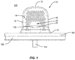
- Figure 1 schematically illustrates a cover 10 that extends over a fastener 110.
- the cover 10 includes a body 13 that forms a cavity 19 with an open first end 11 that extends around the fastener 110.
- the cover 10 also includes a closed second end 12 that extends over the fastener 110 and shields the fastener 110 from a combustible exterior environment 120.
- the cover 10 includes an inner side 14 that faces towards the fastener 110, and an opposing outer side 15. Holes 40 extend through the cover 10 between the inner and outer sides 14, 15. The holes 40 vent gas, liquid, and/or some particles through the cover 10 while removing the thermal and/or kinetic energy that may ignite the combustible exterior environment 120.
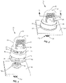
- FIGS 2-4 illustrate a cover 10 that extends over a fastener 110.
- the fastener 110 is connected to one or more members 100.
- the fastener 110 is positioned in a combustible exterior environment 120 and is shielded by the cover 10.
- the fastener 110 includes a body 119 and a head 116.
- the fastener 110 may be any suitable fastener such as a threaded fastener (e.g., a bolt or screw), a stud, a pin, a rivet, etc. and the like.
- the fastener 110 includes metal and/or conductive components that could shunt electrical current and/or be associated with electromagnetic effects that may become ignition sources.
- the fastener 110 can be positioned with the head 116 within the cover 10.
- the fastener 110 can also be positioned with the body 119 positioned within the cover 10.
- the member 100 generally includes a structure (such as a plate) that is non-metallic and that can be less electrically conductive than the fastener 110.
- the member 100 can include and/or can be an electrical insulator (electrically non-conductive) and/or a poor electrical conductor.
- the member 100 can also include an electrical conductor such as electrically-conductive filler and/or reinforcement material (e.g., metallic filler and/or carbon fiber), and/or may include an electrically-conductive layer (e.g., metallic film, metal plate, etc.).
- the member 100 can include, and/or can be constructed of, a polymer (e.g., polyurethane), a composite material (e.g., a carbon fiber-reinforced polymer (CFRP) and/or fiberglass), a ceramic, and/or a metal.
- the member 100 can be a plate, a sheet, a web of material, and/or a larger part of an object (e.g., wing, fuselage).
- the fastener 110 would be exposed to the combustible exterior environment 120 and potentially would present a risk of an ignition event.
- the cover 10 when installed over the fastener 110 positions the fastener 110 within an interior space 16 and isolates the volume of the combustible environment around the fastener 110 from the combustible exterior environment 120. Ignition of the combustible environment that occurs within the interior space 16 does not propagate outside of the cover 10 and does not ignite the combustible exterior environment 120.
- the exterior environment 120 can include a combustible substance and/or mixture.
- combustible exterior environment 120 can include a fuel (e.g., hydrogen, gaseous, liquid, and/or aerosolized hydrocarbon, and/or suspended particulate such as sawdust, etc.), an oxidizer (e.g., oxygen, fluorine, and/or nitrous oxide), and optionally a non-reactive diluent (e.g., nitrogen, argon, and/or helium) with concentrations within the flammability limits of the fuel/oxidizer mixture.
- combustible exterior environment 120 can include a gas that undergoes explosive decomposition (e.g., acetylene, nitrous oxide). Additional specific examples of fuels include motor fuels such as automotive fuel, diesel fuel, aviation fuel, and/or jet fuel.
- Combustible exterior environments 120 can include gases, vapors, aerosols, and/or particulate.
- the cover 10 can prevent the ignition of the combustible exterior environment 120 by preventing a hot particle that is emitted from the fastener 110 from travelling through the cover 10.
- the term "hot particle” refers to a particle that is emitted from the fastener 110 due to an ignition source at the fastener 110 that has a size and/or a thermal energy sufficient to cause ignition of the combustible exterior environment 120.
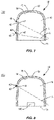
- the cover 10 is configured such that there are no straight-line trajectories through the cover 10 from the fastener 110 to the exterior environment 120 and no line of sight from the exterior environment 120 to the fastener 110. As illustrated in Figure 4 , the cover 10 forms an interior space 16 that extends over the fastener 110.
- the cover 10 includes a body 13 with a first end 11 that is open to extend around the fastener 110, and a second end 12 that is closed and extends over the fastener 110.
- the cover 10 includes an inner side 14 that faces inward towards the interior space 16 and an outer side 15 that faces away. Holes 40 extend through the cover 10 between the inner and outer sides 14, 15.
- the cover 10 can include a unitary, single-piece construction, or a multiple-piece construction. As illustrated in Figure 3 , a multiple-piece cover 10 may include a cap 20 and a base 30.
- the base 30 includes a first end 31 and opposing second end 32.
- the base 30 includes a central opening 33 that forms a portion of the interior space 16.
- the base 30 is configured to support the cap 20 and can be coupled to the cap 20 in various manners, including but not limited to bonding, fusing, welding, heat staking, and adhesive bonding.
- the base 30 can be coupled to the cap 20 by adhesive such as epoxy, cyanoacrylate, polyurethane, polysulfide, etc.
- the base 30 can be coupled to the cap 20 by sintering, welding, etc. (e.g., hot gas welding, polymer welding rod, hot plate welding, contact welding, high frequency welding, induction welding, friction welding, spin welding, laser welding, ultrasonic welding, and/or solvent welding).
- one or both of the base 30 and cap 20 can have snap-fit features that engage together.
- the cap 20 includes a first end 21 and a second end 22.
- the first end 21 is open and configured to contact against the second end 32 of the base 30.
- the second end 22 is closed and extends over the interior space 16.
- the shape and size of the cap 20 can vary.
- One design includes the first end 21 being flared outward with a width at the first end 21 being greater than a width at the second end 22, with the width being measured perpendicular to a longitudinal axis A of the interior space 16.
- the cap 20 can have various thicknesses measured between the inner side 14 and the outer side 15. The thickness can be consistent throughout the cap 20, or can vary.
- One design includes a thickness in a range of between 0.1mm-10mm.
- a more specific design includes a thickness in the range of between 0.5mm-5mm.
- An even more specific design includes a thickness in the range between 1mm-3mm
- the thickness of the cap 20 can be the same or different from the thickness of the base 30.
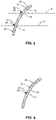
- each of the holes 40 includes a first end 41 at the inner side 14 and a second end 42 at the outer side 15.
- the holes 40 can include various sectional shapes, including but not limited to circular, square, rectangular, elliptical, and filleted rectangles.
- the holes 40 can be straight such that a centerline Y of each of the holes 40 is parallel to one another.
- the holes 40 can also include a bend or corner 44 between the first end 41 and the second end 42. In one design, the bend 44 is formed when the body 13 is injection molded and the molding tools meet along the interior of the body 13.
- Each hole 40 includes a hydraulic diameter, D H .
- the hydraulic diameter D H is equal to four times the flow area divided by the wetted perimeter of the hole 40.
- the hydraulic diameter D H can vary.
- One design includes each of the holes 40 with a hydraulic diameter D H between 0.1 - 2.0 mm.
- Another design includes each of the holes 40 with a hydraulic diameter D H between 0.1 - 1.5 mm.
- Another design includes each of the holes 40 with a hydraulic diameter D H between 0.5 - 1.2 mm.
- the holes 40 vent gas, liquid, and/or particles to flow through the cover 10 while removing the thermal and/or kinetic energy that may ignite the combustible exterior environment 120.
- the holes 40 can also allow drainage of fluid from the interior space 16, such as fuel when the cover 10 is submersed within a fuel tank.
- the number of holes 40 in the cover 10 can vary.
- the cover 10 includes at least four (4) holes.
- the holes 40 extend over between 0.1% - 90% of the surface area of the cover 10.
- One design includes the holes 40 isolated in just the cap 20.
- Another design includes the holes 40 positioned in the cap 20 and the base 30.
- Figure 7 includes a cover 10 with holes 40 configured to prevent a line of sight to the first end 11. This can include a straight line L drawn through any point at the first end 41 of the hole 40 and any point at the second end 42 of the hole 40 does not intersect with the first end 11 of the cover 10.
- Figure 8 includes a cover 10 with a straight line L drawn through any point at the first end 41 of the hole 40 and any point at the second end 42 of the hole 40 does not intersect with the fastener 110.
- the cap 20 includes a masking area 29 at the first end 31.
- the masking area 29 does not include holes 40.
- the masking area 29 prevents a line of sight through the holes 40 to the fastener 110.
- the holes 40 can be configured to prevent a line of sight from the exterior environment 120 to an exclusion zone 50 within the interior space 16.
- the exclusion zone 50 is centered at the intersection of the first end 11 of the cover 10 and the longitudinal axis A of the interior space 16.
- the exclusion zone 50 can include a radius r that extends from the intersection.
- the radius r is sized for the exclusion zone 50 to be large enough to contain the fastener 110.
- the holes 40 are configured for straight lines L drawn through any point at the first end 41 of the hole 40 and any point at the second end 42 of the hole 40 to not intersect with the exclusion zone 50.
- the cover 10 can be constructed from various materials.
- the materials can include but are not limited to polymers, reinforced polymers, polymer composites, and non-conductive ceramics.
- polymers include but are not limited to those that can withstand exposure to jet fuel such as PEEK, nylon, PTFE, polyimide, acetal, PFA, Lytex, Melamine Phenolic, Polybutylene terephthalate, and Torlon.
- the material is conducive to form the cover 10 through injection molding.
- covers 10 that include both a cap 20 and a base 30, the cap 20 and base 30 can be constructed from the same or different materials.
- the base 30 can be constructed from metallic components, such as but not limited to aluminum, titanium, steel.
- the cover 10 is positioned on the member 100.
- the first end 11 can contact directly against the member 100.
- the spacing can be at least partially filled with a spacer 65 (e.g., an O-ring, a gasket).
- the spacing can also be filled with an adhesive 61 (e.g., epoxy, cyanoacrylate, polyurethane, polysulfide, etc.).
- the adhesive 61 can form an airtight seal.
- Unfilled regions of the spacing are sized and/or arranged to prevent a nascent flame front and/or a hot particle from propagating around the cover 10 (through the spacing) and potentially igniting the exterior environment 120.
- the unfilled regions of the spacing can have dimensions smaller than the hydraulic diameter HD.
- the maximum distance between the cover 10 and the member 100 that is not filled (i.e., unfilled regions of the spacing) can be less than 1 mm, less than 0.8 mm, or less than 0.5 mm.
- the cover 10 can be attached to the fastener 110.
- the attachment can include one or more elements that extend from the cover 10 and connect with the fastener 110, one or more elements that extend from the fastener 110 and connect with the cover 10, and combinations thereof. Additionally or alternatively, the attachment can include an adhesive. Further, the adhesive can connect the cover 10 to the member 100. Various adhesives can be used for the attachment, such as but not limited to polysulfide.
- the cover 10 includes a base 30 and a cap 20 with the base 30 being connected to the fastener 110.
- Figures 11-13 include a cover 10 that is connected to the fastener 110.
- the cover 10 includes a cap 20 and a base 30.
- Figure 12 shows the base 30 with a generally annular shape with a central opening 89 that forms a portion of the interior space 16.
- Retention features extend around the central opening 89 to engage with the fastener 110.
- the retention features each include an entry slot 81, a cantilever 82, and a retention slot 83.
- FIG 13 illustrates the fastener 110 engaged with the base 30.
- the fastener 110 includes a body 119 with threads that engage with a nut 118.
- a washer 111 extends around the body 119 and includes tabs 112.
- the tabs 112 and the entry slots 81 are configured to fit together such that the cover 10 can be applied over the fastener 110 after the fastener 110 is installed in the member 100.
- the entry slots 81 extend to the retaining cantilevers 82 and then to the retention slots 83.
- the retaining cantilevers 82 are configured to guide the tabs 112 from the entry slots 81 to the retention slots 83.
- the tabs 112 and/or the retaining cantilevers 82 can be flexible and/or coupled to the respective structure with a flexible arm.
- the cover 10 can be installed with the tabs 112 in the entry slots 81.
- a twist of the cover 10 causes the tabs 112 to be driven up the retaining cantilevers 82 until the tabs 112 clear the retaining cantilevers 82.
- the tabs 112 can snap into the retention slots 83 and/or the retaining cantilevers 82 can snap into place to hold the tabs 112 in the retention slots 83.
- the tabs 112 and/or the retaining cantilevers 82 can make an audible click as the tabs 112 are retained in the retention slots 83 (e.g., to indicate proper installation).
- Figure 12 shows four tabs 112 and four corresponding attachment features on the base 30. Other designs can include different numbers of tabs 112 and attachment features. Also, this design includes the tabs 112 being a portion of the washer 111. However, the tabs 112 can be coupled to or an integral portion of any of the components of the fastener 110 such as the washer 111, the nut 118, and the body 119.
- Figure 14 illustrates a cover 10 coupled to the fastener 110 by a push-style snap lock coupling.
- the base 30 includes one or more rims 84 and the fastener 110 includes one or more shoulders 117.
- the shoulder 117 is a surface that engages the rim 84 and entraps the rim 84 between the shoulder 117 and the member 100.
- the rim 84 can be a continuous annular rim (spanning the entire inner circumference of the cover 10) or can be one or more rims 84 arranged around the inner circumference of the cover 10.
- the rims 84 can be substantially uniformly distributed or asymmetrically distributed about the inner circumference of the cover 10.
- the shoulder 117 can be formed by a combination of two washers 111a, 111b.
- the underside of the upper washer 111a forms the shoulder 117 in the recess formed by the lower washer 111b between the upper washer 111a and the member 100.
- the rim 84 is formed at the edge of the cover 10 as an annular protrusion.
- the rim 84 is configured to flex as the cover 10 is pushed down to the member 100. When the rim 84 is pushed past the shoulder 117, the rim 84 relaxes into the position shown in Figure 14 in which the rim 84 is entrapped between the shoulder 117 and the member 100.
- FIGS 15 and 16 illustrate another base 30.
- Base 30 includes a body 87 with an annular shape with an enclosed central opening 89.
- Cantilevered legs 88 extend outward from an inner side of the body 87 towards the central opening 89. The ends of the legs 88 can be radially spaced inward from the inner side of the body 87.
- Pegs 85 can also be positioned along the inner side of the body 87.
- a gasket 86 can be positioned between the legs 88 and the inner side of the body 87. The gasket 86 is further positioned between ends of the pegs 85 and the bottom edge of the body 87.
- the gasket 86 can conform the base 30 to the member 100 which can have an uneven shape.
- the composite structure of a member 100 in an aircraft is typically not smooth and can contain other irregularities.
- the gasket 86 can accommodate the irregularities and prevent a flow path into the interior space 16 that has a greater hydraulic diameter H D than allowed given the mixture and ignition source.
- the gasket 86 can also prevent a line of sight trajectory for hot particles.
- the gasket 86 includes an annular shape and extends around the base 30.
- the gasket 86 can be constructed from various materials, including but not limited to nitrile rubber and fluorosilicone rubber.
- the gasket 86 can include the same or different thicknesses as different locations.
- the cover 10 can be sized to cover and/or to enclose multiple fasteners 110 as illustrated in Figure 17 .
- the fasteners 110 can be arranged as a row, a circle, an array, a cluster, etc.
- the cover 10 can include a single interior space 16 that is sized to extend over each of the fasteners 110.
- the cover 10 can include two or more separate interior spaces 16 that each are sized to extend over one or more fasteners 110.
- the different interior spaces 16 can be separated by one or more walls.
- the cover 10 can be configured to connect to each of the two or more fasteners 110 that are located in the interior space.
- the cover 10 can be used in a variety of different contexts.
- One use includes on a fuel tank, such as a wing fuel tank in a composite wing aircraft.
- the fastener 110 can be exposed to the fuel volume and/or ullage space (e.g., extending into the interior of the fuel tank) and embedded in and/or coupling one or more members 100 which contact the fuel volume and/or ullage space.
- the members 100 can be carbon-fiber composite panels, partitions, stringers, etc. that are in the interior of the fuel tank and/or define at least a portion of the interior of the fuel tank.
- the cover 10 covers the fastener 110 and is collocated with the fastener 110.
- An ignition source associated with the fastener 110 can develop and trigger an ignition event at the fastener 110.
- the ignition event includes an ignition kernel, a nascent flame front, and/or a pressure wave within the interior space 16 of the cover 10.
- the ignition kernel is quenched by the cover 10; the nascent flame front is quenched as it traverses the cover 10; and/or the pressure wave can be dissipated and/or impeded by the cover 10.
- the cover 10 can be useful in other applications requiring ignition hazard consideration, including fuel transport, fuel storage, mining operations, chemical processing, metal fabrication, power plant construction and operation, and operations which involve combustible particulate such as suspended dust, sawdust, coal, metal, flour, and/or grain.
Landscapes
- Engineering & Computer Science (AREA)
- General Engineering & Computer Science (AREA)
- Mechanical Engineering (AREA)
- Aviation & Aerospace Engineering (AREA)
- Manufacturing & Machinery (AREA)
- Connection Of Plates (AREA)
- Portable Nailing Machines And Staplers (AREA)
Abstract
Description
- The present disclosure relates generally to devices and methods for quenching ignition and, more specifically, to a cover configured to be positioned over a fastener to quench ignition.
- In the aerospace industry, lightning strikes of aircraft are a concern because they could result in electrical arcs, vaporized materials creating hot gas, and/or heating sufficient to ignite vaporous fuel mixtures. Though lightning normally passes through an aircraft without resulting harm, newer aircraft designs incorporate composite materials with less metal and conductors to shunt and/or dissipate the energy of a lightning strike.
- During a lightning strike on an aircraft, a high electrical current may propagate through conductive paths on the aircraft. Due to the non-isotropic electrical conduction of composite materials used in certain aircraft designs and potentially poor electrical connection at panel interfaces, the electrical current can pass through a fastener when propagating from one composite panel to another. While passing through a fastener, the current may generate electromagnetic effects, such as electrical arcs, hot gas, and/or hot particles, that may interact with combustible fuel vapor (in the absence of safety measures). Such an uncontained emission of energy may pose an ignition risk to aircraft fuel tanks. In a typical commercial aircraft, hundreds to thousands of fasteners can extend into the fuel tank, and each should be configured to prevent ignition in the event of a lightning strike.
- As a safety measure, the fasteners can be covered with polysulfide cap seals to seal fuel mixtures in a fuel tank from any arcs, hot gas, or hot particles that may form as a result of a lightning strike. However, these caps require an airtight seal that remains intact during the lightning strike to be effective. Without an airtight seal, fuel may contact the fastener and/or the arc, hot gas, or hot particles can bypass the unsealed cap to present an ignition risk. Additionally, environmental exposure (e.g., thermal cycling) and/or electromagnetic effects at the fastener can damage the seal. Achieving a resilient, airtight seal is a labor-intensive process that may need to be repeated thousands of times per aircraft. The associated installation time as well as inspection time increase the cost and production time of aircraft.
- One aspect is directed to a cover that includes a base with a first end and an opposing second end. A cap with an open end is positioned at the second end of the base. The cap also includes a closed end. A interior space positioned within the base and cap is sized to extend over at least one fastener. Holes extend through the cap from the interior space to an exterior environment external to the cap. Each of the holes includes a hydraulic diameter of between 0.1mm - 2.0mm. One aspect is directed to a cover that includes a body with an open first end and a closed second end, an inner side and an outer side, and an interior space sized to extend over a fastener. Holes extend through the body to allow passage of a fluid from the interior space to an exterior environment. Each of the holes includes a first end at the inner side and a second end at the outer side. An exclusion zone is positioned in the interior space at a center of the first end of the body. Each of the holes is configured such that a straight line that extends between any point at the first end and any point at the second end does not intersect with the exclusion zone.
- One aspect is directed to a method of installing a cover over a fastener. The method includes positioning a cover over a fastener that extends from a member with an open first end of the cover positioned around the fastener and a closed second end of the cover extending over the fastener. The cover includes holes that extend through the cover with a first end on an inner side of the cover and a second end at an outer side of the cover. The method includes aligning the cover over the fastener with the holes aligned to prevent the fastener from being visible through the plurality of holes from an exterior environment.
- The features, functions and advantages that have been discussed can be achieved independently in various aspects or may be combined in yet other aspects, further details of which can be seen with reference to the following description and the drawings.
- Having thus described variations of the disclosure in general terms, reference will now be made to the accompanying drawings, which are not necessarily drawn to scale, and wherein:
-
Figure 1 is a side schematic view of a cover that extends over a fastener in accordance with an embodiment. -
Figure 2 is a perspective view of a cover that extends over a fastener in accordance with an embodiment. -
Figure 3 is an exploded perspective view of the cover ofFigure 2 . -
Figure 4 is a schematic section view of the cover cut along line IV-IV ofFigure 2 . -
Figure 5 is a partial schematic section view of a cover with holes in accordance with an embodiment. -
Figure 6 is a partial schematic section view of a cover with holes in accordance with an embodiment. -
Figure 7 is a schematic section view of holes aligned for a line of sight to be away from a first end of a cover in accordance with an embodiment. -
Figure 8 is a schematic section view of holes aligned for a line of sight to be away from a first end of a fastener in accordance with an embodiment. -
Figure 9 is a schematic section view of holes aligned for a line of sight to be away from an exclusion zone in accordance with an embodiment. -
Figure 10 is a schematic side view of a cover attached to a member in accordance with an embodiment. -
Figure 11 is a perspective view of a cover in accordance with an embodiment. -
Figure 12 is a perspective view of a base in accordance with an embodiment. -
Figure 13 is a schematic section view of a cover cut along line XIII-XIII ofFigure 11 that extends over a fastener in accordance with an embodiment. -
Figure 14 is a schematic section view of a cover that extends over a fastener in accordance with an embodiment. -
Figure 15 is a perspective view of a base in accordance with an embodiment. -
Figure 16 is a schematic section view of the base ofFigure 15 cut along line XVI-XVI. -
Figure 17 is a schematic section view of a cover that extends over multiple fasteners in accordance with an embodiment. -
Figure 1 schematically illustrates acover 10 that extends over afastener 110. Thecover 10 includes abody 13 that forms acavity 19 with an openfirst end 11 that extends around thefastener 110. Thecover 10 also includes a closedsecond end 12 that extends over thefastener 110 and shields thefastener 110 from a combustibleexterior environment 120. Thecover 10 includes aninner side 14 that faces towards thefastener 110, and an opposingouter side 15.Holes 40 extend through thecover 10 between the inner andouter sides holes 40 vent gas, liquid, and/or some particles through thecover 10 while removing the thermal and/or kinetic energy that may ignite the combustibleexterior environment 120. Theholes 40 are aligned to prevent a line of sight from theexterior environment 120 to thefastener 110.Figures 2-4 illustrate acover 10 that extends over afastener 110. Thefastener 110 is connected to one ormore members 100. Thefastener 110 is positioned in a combustibleexterior environment 120 and is shielded by thecover 10. Thefastener 110 includes abody 119 and ahead 116. Thefastener 110 may be any suitable fastener such as a threaded fastener (e.g., a bolt or screw), a stud, a pin, a rivet, etc. and the like. Thefastener 110 includes metal and/or conductive components that could shunt electrical current and/or be associated with electromagnetic effects that may become ignition sources. - The
fastener 110 can be positioned with thehead 116 within thecover 10. Thefastener 110 can also be positioned with thebody 119 positioned within thecover 10. - The
member 100 generally includes a structure (such as a plate) that is non-metallic and that can be less electrically conductive than thefastener 110. Themember 100 can include and/or can be an electrical insulator (electrically non-conductive) and/or a poor electrical conductor. Themember 100 can also include an electrical conductor such as electrically-conductive filler and/or reinforcement material (e.g., metallic filler and/or carbon fiber), and/or may include an electrically-conductive layer (e.g., metallic film, metal plate, etc.). Themember 100 can include, and/or can be constructed of, a polymer (e.g., polyurethane), a composite material (e.g., a carbon fiber-reinforced polymer (CFRP) and/or fiberglass), a ceramic, and/or a metal. Themember 100 can be a plate, a sheet, a web of material, and/or a larger part of an object (e.g., wing, fuselage). Thefastener 110 would be exposed to thecombustible exterior environment 120 and potentially would present a risk of an ignition event. However, thecover 10 when installed over thefastener 110 positions thefastener 110 within aninterior space 16 and isolates the volume of the combustible environment around thefastener 110 from thecombustible exterior environment 120. Ignition of the combustible environment that occurs within theinterior space 16 does not propagate outside of thecover 10 and does not ignite thecombustible exterior environment 120. Theexterior environment 120 can include a combustible substance and/or mixture. For example,combustible exterior environment 120 can include a fuel (e.g., hydrogen, gaseous, liquid, and/or aerosolized hydrocarbon, and/or suspended particulate such as sawdust, etc.), an oxidizer (e.g., oxygen, fluorine, and/or nitrous oxide), and optionally a non-reactive diluent (e.g., nitrogen, argon, and/or helium) with concentrations within the flammability limits of the fuel/oxidizer mixture. As another example,combustible exterior environment 120 can include a gas that undergoes explosive decomposition (e.g., acetylene, nitrous oxide). Additional specific examples of fuels include motor fuels such as automotive fuel, diesel fuel, aviation fuel, and/or jet fuel.Combustible exterior environments 120 can include gases, vapors, aerosols, and/or particulate. - The
cover 10 can prevent the ignition of thecombustible exterior environment 120 by preventing a hot particle that is emitted from thefastener 110 from travelling through thecover 10. As used herein, the term "hot particle" refers to a particle that is emitted from thefastener 110 due to an ignition source at thefastener 110 that has a size and/or a thermal energy sufficient to cause ignition of thecombustible exterior environment 120. Thecover 10 is configured such that there are no straight-line trajectories through thecover 10 from thefastener 110 to theexterior environment 120 and no line of sight from theexterior environment 120 to thefastener 110. As illustrated inFigure 4 , thecover 10 forms aninterior space 16 that extends over thefastener 110. Thecover 10 includes abody 13 with afirst end 11 that is open to extend around thefastener 110, and asecond end 12 that is closed and extends over thefastener 110. Thecover 10 includes aninner side 14 that faces inward towards theinterior space 16 and anouter side 15 that faces away.Holes 40 extend through thecover 10 between the inner andouter sides cover 10 can include a unitary, single-piece construction, or a multiple-piece construction. As illustrated inFigure 3 , a multiple-piece cover 10 may include acap 20 and abase 30. Thebase 30 includes afirst end 31 and opposingsecond end 32. Thebase 30 includes acentral opening 33 that forms a portion of theinterior space 16. Thebase 30 is configured to support thecap 20 and can be coupled to thecap 20 in various manners, including but not limited to bonding, fusing, welding, heat staking, and adhesive bonding. For example, thebase 30 can be coupled to thecap 20 by adhesive such as epoxy, cyanoacrylate, polyurethane, polysulfide, etc. As another example, thebase 30 can be coupled to thecap 20 by sintering, welding, etc. (e.g., hot gas welding, polymer welding rod, hot plate welding, contact welding, high frequency welding, induction welding, friction welding, spin welding, laser welding, ultrasonic welding, and/or solvent welding). As yet another example, one or both of thebase 30 andcap 20 can have snap-fit features that engage together. - The
cap 20 includes afirst end 21 and asecond end 22. Thefirst end 21 is open and configured to contact against thesecond end 32 of thebase 30. Thesecond end 22 is closed and extends over theinterior space 16. The shape and size of thecap 20 can vary. One design includes thefirst end 21 being flared outward with a width at thefirst end 21 being greater than a width at thesecond end 22, with the width being measured perpendicular to a longitudinal axis A of theinterior space 16. - The
cap 20 can have various thicknesses measured between theinner side 14 and theouter side 15. The thickness can be consistent throughout thecap 20, or can vary. One design includes a thickness in a range of between 0.1mm-10mm. A more specific design includes a thickness in the range of between 0.5mm-5mm. An even more specific design includes a thickness in the range between 1mm-3mm The thickness of thecap 20 can be the same or different from the thickness of thebase 30. -
Holes 40 extend through thecap 20 to provide a vent for theinterior space 16. As illustrated inFigure 5 , each of theholes 40 includes afirst end 41 at theinner side 14 and asecond end 42 at theouter side 15. Theholes 40 can include various sectional shapes, including but not limited to circular, square, rectangular, elliptical, and filleted rectangles. Theholes 40 can be straight such that a centerline Y of each of theholes 40 is parallel to one another. As illustrated inFigure 6 , theholes 40 can also include a bend or corner 44 between thefirst end 41 and thesecond end 42. In one design, the bend 44 is formed when thebody 13 is injection molded and the molding tools meet along the interior of thebody 13. - Each
hole 40 includes a hydraulic diameter, DH. The hydraulic diameter DH is equal to four times the flow area divided by the wetted perimeter of thehole 40. The hydraulic diameter DH can be determined at a smallest sectional area of thehole 40. This is defined below in equation [1]:
- A = the cross-sectional area of the hole
- P = the perimeter of the cross-section of the hole
- The hydraulic diameter DH can vary. One design includes each of the
holes 40 with a hydraulic diameter DH between 0.1 - 2.0 mm. Another design includes each of theholes 40 with a hydraulic diameter DH between 0.1 - 1.5 mm. Another design includes each of theholes 40 with a hydraulic diameter DH between 0.5 - 1.2 mm. - The
holes 40 vent gas, liquid, and/or particles to flow through thecover 10 while removing the thermal and/or kinetic energy that may ignite thecombustible exterior environment 120. Theholes 40 can also allow drainage of fluid from theinterior space 16, such as fuel when thecover 10 is submersed within a fuel tank. - The number of
holes 40 in thecover 10 can vary. In one design, thecover 10 includes at least four (4) holes. In one design, theholes 40 extend over between 0.1% - 90% of the surface area of thecover 10. One design includes theholes 40 isolated in just thecap 20. Another design includes theholes 40 positioned in thecap 20 and thebase 30. -
Figure 7 includes acover 10 withholes 40 configured to prevent a line of sight to thefirst end 11. This can include a straight line L drawn through any point at thefirst end 41 of thehole 40 and any point at thesecond end 42 of thehole 40 does not intersect with thefirst end 11 of thecover 10.Figure 8 includes acover 10 with a straight line L drawn through any point at thefirst end 41 of thehole 40 and any point at thesecond end 42 of thehole 40 does not intersect with thefastener 110. - As illustrated in
Figures 2-4 , thecap 20 includes a maskingarea 29 at thefirst end 31. The maskingarea 29 does not include holes 40. The maskingarea 29 prevents a line of sight through theholes 40 to thefastener 110. - The
holes 40 can be configured to prevent a line of sight from theexterior environment 120 to anexclusion zone 50 within theinterior space 16. As illustrated inFigure 9 , theexclusion zone 50 is centered at the intersection of thefirst end 11 of thecover 10 and the longitudinal axis A of theinterior space 16. Theexclusion zone 50 can include a radius r that extends from the intersection. The radius r is sized for theexclusion zone 50 to be large enough to contain thefastener 110. Theholes 40 are configured for straight lines L drawn through any point at thefirst end 41 of thehole 40 and any point at thesecond end 42 of thehole 40 to not intersect with theexclusion zone 50. - The
cover 10 can be constructed from various materials. The materials can include but are not limited to polymers, reinforced polymers, polymer composites, and non-conductive ceramics. Examples of polymers include but are not limited to those that can withstand exposure to jet fuel such as PEEK, nylon, PTFE, polyimide, acetal, PFA, Lytex, Melamine Phenolic, Polybutylene terephthalate, and Torlon. In one design, the material is conducive to form thecover 10 through injection molding. In covers 10 that include both acap 20 and abase 30, thecap 20 andbase 30 can be constructed from the same or different materials. In one design, thebase 30 can be constructed from metallic components, such as but not limited to aluminum, titanium, steel. - The
cover 10 is positioned on themember 100. Thefirst end 11 can contact directly against themember 100. In some designs, there is a spacing between thecover 10 and themember 100. As illustrated inFigures 2-4 , the spacing can be at least partially filled with a spacer 65 (e.g., an O-ring, a gasket). As illustrated inFigure 10 , the spacing can also be filled with an adhesive 61 (e.g., epoxy, cyanoacrylate, polyurethane, polysulfide, etc.). The adhesive 61 can form an airtight seal. Unfilled regions of the spacing are sized and/or arranged to prevent a nascent flame front and/or a hot particle from propagating around the cover 10 (through the spacing) and potentially igniting theexterior environment 120. For example, the unfilled regions of the spacing can have dimensions smaller than the hydraulic diameter HD. The maximum distance between thecover 10 and themember 100 that is not filled (i.e., unfilled regions of the spacing) can be less than 1 mm, less than 0.8 mm, or less than 0.5 mm. - The
cover 10 can be attached to thefastener 110. The attachment can include one or more elements that extend from thecover 10 and connect with thefastener 110, one or more elements that extend from thefastener 110 and connect with thecover 10, and combinations thereof. Additionally or alternatively, the attachment can include an adhesive. Further, the adhesive can connect thecover 10 to themember 100. Various adhesives can be used for the attachment, such as but not limited to polysulfide. In one design, thecover 10 includes abase 30 and acap 20 with the base 30 being connected to thefastener 110. -
Figures 11-13 include acover 10 that is connected to thefastener 110. As illustrated inFigure 11 , thecover 10 includes acap 20 and abase 30.Figure 12 shows the base 30 with a generally annular shape with acentral opening 89 that forms a portion of theinterior space 16. Retention features extend around thecentral opening 89 to engage with thefastener 110. The retention features each include anentry slot 81, acantilever 82, and aretention slot 83. -
Figure 13 illustrates thefastener 110 engaged with thebase 30. Thefastener 110 includes abody 119 with threads that engage with anut 118. Awasher 111 extends around thebody 119 and includestabs 112. Thetabs 112 and theentry slots 81 are configured to fit together such that thecover 10 can be applied over thefastener 110 after thefastener 110 is installed in themember 100. Theentry slots 81 extend to the retainingcantilevers 82 and then to theretention slots 83. The retaining cantilevers 82 are configured to guide thetabs 112 from theentry slots 81 to theretention slots 83. Thetabs 112 and/or the retainingcantilevers 82 can be flexible and/or coupled to the respective structure with a flexible arm. Thecover 10 can be installed with thetabs 112 in theentry slots 81. A twist of thecover 10 causes thetabs 112 to be driven up the retainingcantilevers 82 until thetabs 112 clear the retainingcantilevers 82. Once thetabs 112 clear the retainingcantilevers 82, thetabs 112 can snap into theretention slots 83 and/or the retainingcantilevers 82 can snap into place to hold thetabs 112 in theretention slots 83. Thetabs 112 and/or the retainingcantilevers 82 can make an audible click as thetabs 112 are retained in the retention slots 83 (e.g., to indicate proper installation). -
Figure 12 shows fourtabs 112 and four corresponding attachment features on thebase 30. Other designs can include different numbers oftabs 112 and attachment features. Also, this design includes thetabs 112 being a portion of thewasher 111. However, thetabs 112 can be coupled to or an integral portion of any of the components of thefastener 110 such as thewasher 111, thenut 118, and thebody 119. -
Figure 14 illustrates acover 10 coupled to thefastener 110 by a push-style snap lock coupling. Thebase 30 includes one ormore rims 84 and thefastener 110 includes one ormore shoulders 117. Theshoulder 117 is a surface that engages therim 84 and entraps therim 84 between theshoulder 117 and themember 100. Therim 84 can be a continuous annular rim (spanning the entire inner circumference of the cover 10) or can be one ormore rims 84 arranged around the inner circumference of thecover 10. Therims 84 can be substantially uniformly distributed or asymmetrically distributed about the inner circumference of thecover 10. - The
shoulder 117 can be formed by a combination of twowashers upper washer 111a forms theshoulder 117 in the recess formed by thelower washer 111b between theupper washer 111a and themember 100. In the example ofFigure 14 , therim 84 is formed at the edge of thecover 10 as an annular protrusion. Therim 84 is configured to flex as thecover 10 is pushed down to themember 100. When therim 84 is pushed past theshoulder 117, therim 84 relaxes into the position shown inFigure 14 in which therim 84 is entrapped between theshoulder 117 and themember 100. -
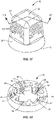
Figures 15 and 16 illustrate anotherbase 30.Base 30 includes abody 87 with an annular shape with an enclosedcentral opening 89.Cantilevered legs 88 extend outward from an inner side of thebody 87 towards thecentral opening 89. The ends of thelegs 88 can be radially spaced inward from the inner side of thebody 87.Pegs 85 can also be positioned along the inner side of thebody 87. A gasket 86 can be positioned between thelegs 88 and the inner side of thebody 87. The gasket 86 is further positioned between ends of thepegs 85 and the bottom edge of thebody 87. The gasket 86 can conform the base 30 to themember 100 which can have an uneven shape. In one use, the composite structure of amember 100 in an aircraft is typically not smooth and can contain other irregularities. The gasket 86 can accommodate the irregularities and prevent a flow path into theinterior space 16 that has a greater hydraulic diameter HD than allowed given the mixture and ignition source. The gasket 86 can also prevent a line of sight trajectory for hot particles. The gasket 86 includes an annular shape and extends around thebase 30. The gasket 86 can be constructed from various materials, including but not limited to nitrile rubber and fluorosilicone rubber. The gasket 86 can include the same or different thicknesses as different locations. - The
cover 10 can be sized to cover and/or to enclosemultiple fasteners 110 as illustrated inFigure 17 . Thefasteners 110 can be arranged as a row, a circle, an array, a cluster, etc. Thecover 10 can include a singleinterior space 16 that is sized to extend over each of thefasteners 110. Thecover 10 can include two or more separateinterior spaces 16 that each are sized to extend over one ormore fasteners 110. The differentinterior spaces 16 can be separated by one or more walls. Thecover 10 can be configured to connect to each of the two ormore fasteners 110 that are located in the interior space. - The
cover 10 can be used in a variety of different contexts. One use includes on a fuel tank, such as a wing fuel tank in a composite wing aircraft. Thefastener 110 can be exposed to the fuel volume and/or ullage space (e.g., extending into the interior of the fuel tank) and embedded in and/or coupling one ormore members 100 which contact the fuel volume and/or ullage space. Themembers 100 can be carbon-fiber composite panels, partitions, stringers, etc. that are in the interior of the fuel tank and/or define at least a portion of the interior of the fuel tank. Thecover 10 covers thefastener 110 and is collocated with thefastener 110. An ignition source associated with thefastener 110 can develop and trigger an ignition event at thefastener 110. For example, due to, e.g., a lightning strike or the friction of fuel movement, electrical charge and/or an electrical voltage may develop at thefastener 110 sufficient to cause an electrical discharge or other potential ignition source. The ignition event includes an ignition kernel, a nascent flame front, and/or a pressure wave within theinterior space 16 of thecover 10. The ignition kernel is quenched by thecover 10; the nascent flame front is quenched as it traverses thecover 10; and/or the pressure wave can be dissipated and/or impeded by thecover 10. - The
cover 10 can be useful in other applications requiring ignition hazard consideration, including fuel transport, fuel storage, mining operations, chemical processing, metal fabrication, power plant construction and operation, and operations which involve combustible particulate such as suspended dust, sawdust, coal, metal, flour, and/or grain. - Further, the disclosure comprises embodiments according to the following clauses:
- Clause 1. A cover, comprising:
- a base comprising a first end and an opposing second end;
- a cap comprising an open end positioned at the second end of the base, the cap further comprising a closed end;
- an interior space positioned within the base and the cap and that is sized to extend over at least one fastener; and
- a plurality of holes that extend through the cap from the interior space to an exterior environment external to the cap, each of the holes comprises a hydraulic diameter of between 0.1mm - 2.0mm.
- Clause 2. The cover of clause 1, wherein:
- the interior space comprises a longitudinal axis that extends through the first end of the base;
- an exclusion zone positioned in the interior space at an intersection of the first end and the longitudinal axis; and
- the holes are aligned to prevent a line of sight through the holes from the exterior environment to the exclusion zone.
- Clause 3. The cover of any of clauses 1-2, wherein the holes comprise between 0.1% - 90% of a surface area of the cap and the base.
- Clause 4. The cover of any of clauses 1-3, wherein each of the holes comprises a centerline that is straight, and wherein the centerlines of each of the holes are parallel.
- Clause 5. The cover of any of clauses 1-4, wherein each of the holes comprises a bend between a first end of the hole and a second end of the hole.
- Clause 6. The cover of any of clauses 1-5, wherein the cap comprises a masking area that is devoid of the holes, the masking area extending from the open end towards the closed end.
- Clause 7. The cover of any of clauses 1-6, wherein the open end of the cap has a greater width than the closed end with the width being measured perpendicular to a longitudinal axis of the cap.
- Clause 8. The cover of any of clauses 1-7, wherein the holes are aligned to prevent a line of sight from the exterior environment to the first end of the base.
- Clause 9. The cover of any of clauses 1-8, further comprising a gasket positioned at the first end of the base, the gasket configured to conform the first end of the base against a member.
-
Clause 10. A cover, comprising:- a body comprising an open first end and a closed second end, an inner side and an outer side, and an interior space sized to extend over a fastener; and
- a plurality of holes that extend through the body to allow passage of a fluid from the interior space to an exterior environment, each of the holes comprising a first end at the inner side and a second end at the outer side; and
- an exclusion zone positioned in the interior space at a center of the first end of the body, each of the holes is configured such that a straight line that extends between any point at the first end and any point at the second end does not intersect with the exclusion zone.
-
Clause 11. The cover ofclause 10, wherein each of the holes comprises a hydraulic diameter of between 0.1mm - 2.0mm -
Clause 12. The cover of any of clauses 9-10, wherein the body comprises a base with a first end and a second end, and a cap attached to the base and positioned at the second end of the base. -
Clause 13. The cover ofclause 12, wherein the interior space is sized to extend over two or more of the fasteners. -
Clause 14. The cover of any of clauses 10-13, wherein the cover is mounted in a fuel cell of an aircraft and configured to quench an ignition event in the fuel cell triggered by an ignition source associated with a fastener. -
Clause 15. The cover of any of clauses 10-14, wherein each of the holes is straight and wherein each of the holes includes a centerline, with the centerlines of each of the holes being parallel. -
Clause 16. The cover of clauses 10-15, wherein the holes are aligned to prevent a line of sight through the holes from the exterior environment to the first end of the body. - Clause 17. A method of installing a cover over a fastener, the method comprising:
- positioning a cover over a fastener that extends from a member with an open first end of the cover positioned around the fastener and a closed second end of the cover extending over the fastener, the cover comprising a plurality of holes that extend through the cover with a first end on an inner side of the cover and a second end at an outer side of the cover; and
- aligning the cover over the fastener with the holes aligned to prevent the fastener from being visible through the plurality of holes from an exterior environment.
- Clause 18. The method of clause 17, wherein aligning the cover over the fastener comprises aligning the cover such that for each hole a straight line that extends through any point at the second end of the hole and any point at the first end of the hole does not intersect with the fastener.
-
Clause 19. The method of any of clauses 17-18, further comprising aligning a solid section of the cover adjacent to the fastener and aligning the holes farther away from the fastener. -
Clause 20. The method of any of clauses 17-19, further comprising positioning the cover over the fastener and at least one other fastener. - Clause 1A. A cover, comprising:
- a base comprising a first end and an opposing second end;
- a cap comprising an open end positioned at the second end of the base, the cap further comprising a closed end;
- an interior space positioned within the base and the cap and that is sized to extend over at least one fastener; and
- a plurality of holes that extend through the cap from the interior space to an exterior environment external to the cap, each of the holes comprises a hydraulic diameter of between 0.1mm - 2.0mm.
- Clause 2A. The cover of clause 1A, wherein:
- the interior space comprises a longitudinal axis that extends through the first end of the base;
- an exclusion zone positioned in the interior space at an intersection of the first end and the longitudinal axis; and
- the holes are aligned to prevent a line of sight through the holes from the exterior environment to the exclusion zone.
- Clause 3A. The cover of any of clauses 1A-2A, wherein the holes comprise between 0.1% - 90% of a surface area of the cap and the base.
- Clause 4A. The cover of any of clauses 1A-3A, wherein each of the holes comprises a centerline that is straight, and wherein the centerlines of each of the holes are parallel.
- Clause 5A. The cover of any of clauses 1A-4A, wherein each of the holes comprises a bend between a first end of the hole and a second end of the hole.
- Clause 6A. The cover of any of clauses 1A-5A, wherein the cap comprises a masking area that is devoid of the holes, the masking area extending from the open end towards the closed end.
- Clause 7A. The cover of any of clauses 1A-6A, wherein the open end of the cap has a greater width than the closed end with the width being measured perpendicular to a longitudinal axis of the cap.
- Clause 8A. The cover of any of clauses 1A-7A, wherein the holes are aligned to prevent a line of sight from the exterior environment to the first end of the base.
- Clause 9A. The cover of any of clauses 1A-8A, further comprising a gasket positioned at the first end of the base, the gasket configured to conform the first end of the base against a member.
- Clause 10A. A method of installing a cover over a fastener, the method comprising:
- positioning a cover over a fastener that extends from a member with an open first end of the cover positioned around the fastener and a closed second end of the cover extending over the fastener, the cover comprising a plurality of holes that extend through the cover with a first end on an inner side of the cover and a second end at an outer side of the cover; and
- aligning the cover over the fastener with the holes aligned to prevent the fastener from being visible through the plurality of holes from an exterior environment.
- Clause 11A. The method of clause 10A, wherein aligning the cover over the fastener comprises aligning the cover such that for each hole a straight line that extends through any point at the second end of the hole and any point at the first end of the hole does not intersect with the fastener.
- Clause 12A. The method of any of clauses 10A-11A, further comprising aligning a solid section of the cover adjacent to the fastener and aligning the holes farther away from the fastener.
- Clause 13A. The method of any of clauses 10A-12A, further comprising positioning the cover over the fastener and at least one other fastener.
- The present invention may be carried out in other ways than those specifically set forth herein without departing from essential characteristics of the invention. The present embodiments are to be considered in all respects as illustrative and not restrictive, and all changes coming within the meaning and equivalency range of the appended claims are intended to be embraced therein.
Claims (15)
- A cover, comprising:a base (30) comprising a first end (31) and an opposing second end (32);a cap (20) comprising an open end (21) positioned at the second end (32) of the base (30), the cap (20) further comprising a closed end (22);an interior space (16) positioned within the base (30) and the cap (20) and that is sized to extend over at least one fastener (110); anda plurality of holes (40) that extend through the cap (20) from the interior space (16) to an exterior environment external to the cap (20), each of the holes (40) comprises a hydraulic diameter of between 0.1mm - 2.0mm,wherein each of the holes (40) comprises a bend between a first end (41) of the hole (40) and a second end (42) of the hole (40).
- The cover of claim 1, wherein:the interior space (16) comprises a longitudinal axis that extends through the first end (31) of the base (30);an exclusion zone (50) positioned in the interior space (16) at an intersection of the first end (31) and the longitudinal axis; andthe holes (40) are aligned to prevent a line of sight through the holes (40) from the exterior environment to the exclusion zone (50).
- The cover of any of claims 1-2, wherein the holes (40) comprise between 0.1% - 90% of a surface area of the cap (20) and the base (30).
- The cover of any of claims 1-3, wherein each of the holes (40) comprises a centerline that is straight, and wherein the centerlines of each of the holes (40) are parallel.
- The cover of any of claims 1-4, wherein the cap (20) comprises a masking area (29) that is devoid of the holes (40), the masking area (29) extending from the open end (21) towards the closed end (22).
- The cover of any of claims 1-5, wherein the open end (21) of the cap (20) has a greater width than the closed end (22) with the width being measured perpendicular to a longitudinal axis of the cap (20).
- The cover of any of claims 1-6, wherein the holes (40) are aligned to prevent a line of sight from the exterior environment to the first end (31) of the base (30).
- The cover of any of claims 1-7, further comprising a gasket (58) positioned at the first end of the base (30), the gasket (58) configured to conform the first end (31) of the base (30) against a member (100).
- The cover of any of claims 1-8, wherein the holes (40) comprise one of the following sectional shapes: circular, square, rectangular, elliptical or filleted rectangles.
- The cover of any of claims 1-9, wherein the cover is a unitary, single-piece construction.
- The cover of any of claims 1-9, wherein the cover is a multiple-piece construction.
- The cover of claim 11, wherein the base (30) is coupled to the cap (20) by adhesive bonding.
- The cover of claim 12, wherein the adhesive comprises epoxy, cyanoacrylate, polyurethane or polysulfide.
- The cover of claim 11, wherein the base (30) is coupled to the cap (20) by sintering, hot gas welding, a polymer welding rod, hot plate welding, contact welding, high frequency welding, induction welding, friction welding, spin welding, laser welding, ultrasonic welding and/or solvent welding.
- The cover of claim 11, wherein the base (30) and the cap (20) have snap-fit features that engage together.
Applications Claiming Priority (3)
| Application Number | Priority Date | Filing Date | Title |
|---|---|---|---|
| US201862729677P | 2018-09-11 | 2018-09-11 | |
| US16/209,312 US11078947B2 (en) | 2018-09-11 | 2018-12-04 | Combustion quenching fastener caps with holes |
| EP19195734.9A EP3623298B1 (en) | 2018-09-11 | 2019-09-05 | Combustion quenching fastener caps with holes |
Related Parent Applications (2)
| Application Number | Title | Priority Date | Filing Date |
|---|---|---|---|
| EP19195734.9A Division EP3623298B1 (en) | 2018-09-11 | 2019-09-05 | Combustion quenching fastener caps with holes |
| EP19195734.9A Division-Into EP3623298B1 (en) | 2018-09-11 | 2019-09-05 | Combustion quenching fastener caps with holes |
Publications (2)
| Publication Number | Publication Date |
|---|---|
| EP4119445A1 true EP4119445A1 (en) | 2023-01-18 |
| EP4119445B1 EP4119445B1 (en) | 2024-04-10 |
Family
ID=67874399
Family Applications (2)
| Application Number | Title | Priority Date | Filing Date |
|---|---|---|---|
| EP22193123.1A Active EP4119445B1 (en) | 2018-09-11 | 2019-09-05 | Combustion quenching fastener caps with holes |
| EP19195734.9A Active EP3623298B1 (en) | 2018-09-11 | 2019-09-05 | Combustion quenching fastener caps with holes |
Family Applications After (1)
| Application Number | Title | Priority Date | Filing Date |
|---|---|---|---|
| EP19195734.9A Active EP3623298B1 (en) | 2018-09-11 | 2019-09-05 | Combustion quenching fastener caps with holes |
Country Status (7)
| Country | Link |
|---|---|
| US (1) | US11078947B2 (en) |
| EP (2) | EP4119445B1 (en) |
| JP (1) | JP7449658B2 (en) |
| CN (1) | CN110884670B (en) |
| AU (1) | AU2019222903B2 (en) |
| CA (1) | CA3053580C (en) |
| ES (2) | ES2936619T3 (en) |
Families Citing this family (6)
| Publication number | Priority date | Publication date | Assignee | Title |
|---|---|---|---|---|
| JP2020020387A (en) * | 2018-07-31 | 2020-02-06 | 三菱重工業株式会社 | Cap seal, fastening structure including the same, and cap seal attachment method |
| US11078947B2 (en) | 2018-09-11 | 2021-08-03 | The Boeing Company | Combustion quenching fastener caps with holes |
| US11022164B2 (en) * | 2018-09-11 | 2021-06-01 | The Boeing Company | Double shell fastener caps |
| US11788573B2 (en) | 2019-05-23 | 2023-10-17 | The Boeing Company | Multi-component melt electromagnetic effect protection cap system |
| US11754111B2 (en) | 2020-03-16 | 2023-09-12 | The Boeing Company | Compression fit EME protection seal cap |
| EP4001124B1 (en) | 2020-11-19 | 2024-02-07 | The Boeing Company | Seal-cover assembly for an aircraft or other structure and a method of assembling the same |
Citations (7)
| Publication number | Priority date | Publication date | Assignee | Title |
|---|---|---|---|---|
| GB1492206A (en) * | 1974-11-15 | 1977-11-16 | Sibe | Screw devices for carburettor adjustment |
| US5749690A (en) * | 1997-03-17 | 1998-05-12 | Kutz; Kurt | Screw nut fastener assembly |
| EP2860410A1 (en) * | 2013-09-23 | 2015-04-15 | The Boeing Company | Systems and methods for use in covering a portion of a fastener protruding from a surface |
| CN105179432A (en) * | 2015-10-14 | 2015-12-23 | 无锡市永亿精密铸造有限公司 | Automotive hub nut capable of being cooled with dry ice |
| US9744923B2 (en) * | 2014-05-09 | 2017-08-29 | Steve Parenti | Secure attachment |
| EP3232071A1 (en) * | 2016-04-15 | 2017-10-18 | The Boeing Company | Telescoping cap assembly for encapsulating a fastener disposed within a confined space |
| US9951804B2 (en) * | 2014-12-16 | 2018-04-24 | Airbus Operations Limited | Spark containment cap |
Family Cites Families (34)
| Publication number | Priority date | Publication date | Assignee | Title |
|---|---|---|---|---|
| US2173046A (en) | 1938-10-15 | 1939-09-12 | Harry T Smith | Saltcellar |
| US3351214A (en) * | 1962-06-25 | 1967-11-07 | Ohio Brass Co | Shear bolt |
| US3470787A (en) | 1968-03-27 | 1969-10-07 | Us Army | Corrosion prevention device and method |
| US4519974A (en) | 1983-08-12 | 1985-05-28 | Ltv Aerospace And Defense Company | Method and apparatus for applying a sealant to exposed fasteners |
| US4636446A (en) | 1985-11-15 | 1987-01-13 | Cheng Kwang Storage Battery Co., Ltd. | Stopper structure for storage battery container |
| US4826380A (en) | 1988-01-19 | 1989-05-02 | Ltv Aerospace & Defense Company | Pre-cast sealant dome and method |
| US4820097A (en) * | 1988-03-18 | 1989-04-11 | United Technologies Corporation | Fastener with airflow opening |
| US5108853A (en) | 1990-12-20 | 1992-04-28 | Exide Corporation | Submersible and flame retardant battery vent plug |
| US5890859A (en) * | 1997-12-22 | 1999-04-06 | Hasnik; Dean C. | Security arrangement for deterring removal of a nut or bolt |
| DE19826799C1 (en) * | 1998-06-16 | 2000-03-09 | Ejot Kunststofftech Gmbh | Fixture device for covering or retainer on sub-construction has body with head and base opposite to which is base and hollow space between head and base |
| US6425720B1 (en) | 2000-02-28 | 2002-07-30 | Hy Kramer | Substrate attaching member |
| WO2004061316A1 (en) * | 2002-12-26 | 2004-07-22 | Nishioka Byoura Co., Ltd. | Tightened part disconnection preventing device |
| ES2342641B1 (en) | 2007-11-15 | 2011-04-25 | Airbus España S.L. | PROTECTION DEVICE AGAINST ELECTRIC SHOCK IN ELEMENTS DEFIXATION WITH ELEVATED LOAD. |
| US8292592B2 (en) | 2008-04-02 | 2012-10-23 | United Technologies Corporation | Nosecone bolt access and aerodynamic leakage baffle |
| US8366367B2 (en) | 2008-12-30 | 2013-02-05 | Brian Matlock | Nut and bolt cover |
| JP5610758B2 (en) * | 2009-04-02 | 2014-10-22 | 三菱航空機株式会社 | Lightning-resistant fastener, cap, lightning-fastener installation method, aircraft |
| EP2673193B1 (en) | 2011-02-10 | 2018-07-11 | Airbus Operations Limited | Cap for forming sealed cavity around fastener |
| US8616868B2 (en) | 2011-02-28 | 2013-12-31 | Physical Systems, Inc. | Sealant mold fixture for a domed cap |
| WO2012147645A1 (en) | 2011-04-28 | 2012-11-01 | 三菱重工業株式会社 | Cap and affixation structure section using same |
| JP5931458B2 (en) | 2012-01-17 | 2016-06-08 | 三菱航空機株式会社 | How to install lightning-resistant fasteners and lightning-resistant fasteners |
| GB201214579D0 (en) | 2012-08-15 | 2012-09-26 | Airbus Operations Ltd | Flanged cap for forming sealed cavity around fastener |
| US10051767B2 (en) | 2012-09-28 | 2018-08-14 | The Boeing Company | Method and apparatus for covering a fastener system |
| GB201305459D0 (en) * | 2013-01-30 | 2013-05-08 | Short Brothers Plc | Electrical protector |
| GB2514171B (en) | 2013-05-16 | 2015-11-25 | Airbus Operations Ltd | Injectable nut cap |
| US9188226B2 (en) | 2013-07-15 | 2015-11-17 | The Boeing Company | Apparatus for installing a seal cap |
| KR20160044495A (en) | 2013-08-21 | 2016-04-25 | 에어버스 오퍼레이션즈 리미티드 | Cap with injected sealant |
| US9618029B2 (en) | 2013-09-23 | 2017-04-11 | The Boeing Company | Systems and methods for use in covering a portion of a fastener protruding from a surface |
| GB2535168A (en) | 2015-02-09 | 2016-08-17 | Airbus Operations Ltd | Method of installing a spark containment cap |
| US10512805B2 (en) * | 2015-07-21 | 2019-12-24 | The Boeing Company | Ignition-quenching systems, apparatuses, and methods |
| JP6821108B2 (en) | 2016-05-10 | 2021-01-27 | 嘉彦 芋田 | Anti-corrosion caps for bolts and nuts |
| FR3067767B1 (en) * | 2017-06-15 | 2019-07-19 | Lisi Aerospace | POSITIVE LOCK FASTENING |
| US10501202B2 (en) * | 2017-08-23 | 2019-12-10 | The Boeing Company | Ignition-quenching systems, apparatuses, and methods |
| JP6434116B2 (en) * | 2017-12-18 | 2018-12-05 | 三菱重工業株式会社 | Cap and fixing structure using the cap |
| US11078947B2 (en) | 2018-09-11 | 2021-08-03 | The Boeing Company | Combustion quenching fastener caps with holes |
-
2018
- 2018-12-04 US US16/209,312 patent/US11078947B2/en active Active
-
2019
- 2019-08-28 CA CA3053580A patent/CA3053580C/en active Active
- 2019-08-29 AU AU2019222903A patent/AU2019222903B2/en active Active
- 2019-09-02 JP JP2019159384A patent/JP7449658B2/en active Active
- 2019-09-03 CN CN201910825773.6A patent/CN110884670B/en active Active
- 2019-09-05 EP EP22193123.1A patent/EP4119445B1/en active Active
- 2019-09-05 ES ES19195734T patent/ES2936619T3/en active Active
- 2019-09-05 EP EP19195734.9A patent/EP3623298B1/en active Active
- 2019-09-05 ES ES22193123T patent/ES2983115T3/en active Active
Patent Citations (7)
| Publication number | Priority date | Publication date | Assignee | Title |
|---|---|---|---|---|
| GB1492206A (en) * | 1974-11-15 | 1977-11-16 | Sibe | Screw devices for carburettor adjustment |
| US5749690A (en) * | 1997-03-17 | 1998-05-12 | Kutz; Kurt | Screw nut fastener assembly |
| EP2860410A1 (en) * | 2013-09-23 | 2015-04-15 | The Boeing Company | Systems and methods for use in covering a portion of a fastener protruding from a surface |
| US9744923B2 (en) * | 2014-05-09 | 2017-08-29 | Steve Parenti | Secure attachment |
| US9951804B2 (en) * | 2014-12-16 | 2018-04-24 | Airbus Operations Limited | Spark containment cap |
| CN105179432A (en) * | 2015-10-14 | 2015-12-23 | 无锡市永亿精密铸造有限公司 | Automotive hub nut capable of being cooled with dry ice |
| EP3232071A1 (en) * | 2016-04-15 | 2017-10-18 | The Boeing Company | Telescoping cap assembly for encapsulating a fastener disposed within a confined space |
Also Published As
| Publication number | Publication date |
|---|---|
| CA3053580C (en) | 2023-11-14 |
| JP2020059488A (en) | 2020-04-16 |
| EP4119445B1 (en) | 2024-04-10 |
| CN110884670B (en) | 2024-07-02 |
| EP3623298A1 (en) | 2020-03-18 |
| US11078947B2 (en) | 2021-08-03 |
| AU2019222903B2 (en) | 2024-07-18 |
| CA3053580A1 (en) | 2020-03-11 |
| AU2019222903A1 (en) | 2020-03-26 |
| CN110884670A (en) | 2020-03-17 |
| US20200080585A1 (en) | 2020-03-12 |
| JP7449658B2 (en) | 2024-03-14 |
| ES2983115T3 (en) | 2024-10-21 |
| EP3623298B1 (en) | 2022-11-02 |
| ES2936619T3 (en) | 2023-03-21 |
Similar Documents
| Publication | Publication Date | Title |
|---|---|---|
| EP3623298B1 (en) | Combustion quenching fastener caps with holes | |
| CA3053378C (en) | Double shell fastener caps | |
| US10501202B2 (en) | Ignition-quenching systems, apparatuses, and methods | |
| US11571595B2 (en) | Ignition-quenching covers and methods for aerospace applications | |
| US12264699B2 (en) | Attachment of ignition suppression or quenching device to a fastener stack |
Legal Events
| Date | Code | Title | Description |
|---|---|---|---|
| PUAI | Public reference made under article 153(3) epc to a published international application that has entered the european phase |
Free format text: ORIGINAL CODE: 0009012 |
|
| STAA | Information on the status of an ep patent application or granted ep patent |
Free format text: STATUS: THE APPLICATION HAS BEEN PUBLISHED |
|
| AC | Divisional application: reference to earlier application |
Ref document number: 3623298 Country of ref document: EP Kind code of ref document: P |
|
| AK | Designated contracting states |
Kind code of ref document: A1 Designated state(s): AL AT BE BG CH CY CZ DE DK EE ES FI FR GB GR HR HU IE IS IT LI LT LU LV MC MK MT NL NO PL PT RO RS SE SI SK SM TR |
|
| STAA | Information on the status of an ep patent application or granted ep patent |
Free format text: STATUS: REQUEST FOR EXAMINATION WAS MADE |
|
| RAP3 | Party data changed (applicant data changed or rights of an application transferred) |
Owner name: THE BOEING COMPANY |
|
| 17P | Request for examination filed |
Effective date: 20230228 |
|
| RBV | Designated contracting states (corrected) |
Designated state(s): AL AT BE BG CH CY CZ DE DK EE ES FI FR GB GR HR HU IE IS IT LI LT LU LV MC MK MT NL NO PL PT RO RS SE SI SK SM TR |
|
| GRAP | Despatch of communication of intention to grant a patent |
Free format text: ORIGINAL CODE: EPIDOSNIGR1 |
|
| STAA | Information on the status of an ep patent application or granted ep patent |
Free format text: STATUS: GRANT OF PATENT IS INTENDED |
|
| RIC1 | Information provided on ipc code assigned before grant |
Ipc: B64D 37/32 20060101ALN20230426BHEP Ipc: F16B 37/14 20060101ALI20230426BHEP Ipc: F16B 33/00 20060101ALI20230426BHEP Ipc: B64D 45/02 20060101AFI20230426BHEP |
|
| INTG | Intention to grant announced |
Effective date: 20230524 |
|
| P01 | Opt-out of the competence of the unified patent court (upc) registered |
Effective date: 20230808 |
|
| GRAJ | Information related to disapproval of communication of intention to grant by the applicant or resumption of examination proceedings by the epo deleted |
Free format text: ORIGINAL CODE: EPIDOSDIGR1 |
|
| STAA | Information on the status of an ep patent application or granted ep patent |
Free format text: STATUS: REQUEST FOR EXAMINATION WAS MADE |
|
| GRAP | Despatch of communication of intention to grant a patent |
Free format text: ORIGINAL CODE: EPIDOSNIGR1 |
|
| STAA | Information on the status of an ep patent application or granted ep patent |
Free format text: STATUS: GRANT OF PATENT IS INTENDED |
|
| INTC | Intention to grant announced (deleted) | ||
| RIC1 | Information provided on ipc code assigned before grant |
Ipc: B64D 37/32 20060101ALN20230926BHEP Ipc: F16B 37/14 20060101ALI20230926BHEP Ipc: F16B 33/00 20060101ALI20230926BHEP Ipc: B64D 45/02 20060101AFI20230926BHEP |
|
| INTG | Intention to grant announced |
Effective date: 20231024 |
|
| GRAS | Grant fee paid |
Free format text: ORIGINAL CODE: EPIDOSNIGR3 |
|
| GRAA | (expected) grant |
Free format text: ORIGINAL CODE: 0009210 |
|
| STAA | Information on the status of an ep patent application or granted ep patent |
Free format text: STATUS: THE PATENT HAS BEEN GRANTED |
|
| AC | Divisional application: reference to earlier application |
Ref document number: 3623298 Country of ref document: EP Kind code of ref document: P |
|
| AK | Designated contracting states |
Kind code of ref document: B1 Designated state(s): AL AT BE BG CH CY CZ DE DK EE ES FI FR GB GR HR HU IE IS IT LI LT LU LV MC MK MT NL NO PL PT RO RS SE SI SK SM TR |
|
| REG | Reference to a national code |
Ref country code: GB Ref legal event code: FG4D |
|
| REG | Reference to a national code |
Ref country code: CH Ref legal event code: EP |
|
| REG | Reference to a national code |
Ref country code: DE Ref legal event code: R096 Ref document number: 602019050300 Country of ref document: DE |
|
| REG | Reference to a national code |
Ref country code: IE Ref legal event code: FG4D |
|
| REG | Reference to a national code |
Ref country code: LT Ref legal event code: MG9D |
|
| REG | Reference to a national code |
Ref country code: NL Ref legal event code: MP Effective date: 20240410 |
|
| REG | Reference to a national code |
Ref country code: AT Ref legal event code: MK05 Ref document number: 1674694 Country of ref document: AT Kind code of ref document: T Effective date: 20240410 |
|
| PG25 | Lapsed in a contracting state [announced via postgrant information from national office to epo] |
Ref country code: NL Free format text: LAPSE BECAUSE OF FAILURE TO SUBMIT A TRANSLATION OF THE DESCRIPTION OR TO PAY THE FEE WITHIN THE PRESCRIBED TIME-LIMIT Effective date: 20240410 |
|
| PG25 | Lapsed in a contracting state [announced via postgrant information from national office to epo] |
Ref country code: NL Free format text: LAPSE BECAUSE OF FAILURE TO SUBMIT A TRANSLATION OF THE DESCRIPTION OR TO PAY THE FEE WITHIN THE PRESCRIBED TIME-LIMIT Effective date: 20240410 |
|
| PG25 | Lapsed in a contracting state [announced via postgrant information from national office to epo] |
Ref country code: IS Free format text: LAPSE BECAUSE OF FAILURE TO SUBMIT A TRANSLATION OF THE DESCRIPTION OR TO PAY THE FEE WITHIN THE PRESCRIBED TIME-LIMIT Effective date: 20240810 |
|
| PG25 | Lapsed in a contracting state [announced via postgrant information from national office to epo] |
Ref country code: BG Free format text: LAPSE BECAUSE OF FAILURE TO SUBMIT A TRANSLATION OF THE DESCRIPTION OR TO PAY THE FEE WITHIN THE PRESCRIBED TIME-LIMIT Effective date: 20240410 |
|
| PG25 | Lapsed in a contracting state [announced via postgrant information from national office to epo] |
Ref country code: FI Free format text: LAPSE BECAUSE OF FAILURE TO SUBMIT A TRANSLATION OF THE DESCRIPTION OR TO PAY THE FEE WITHIN THE PRESCRIBED TIME-LIMIT Effective date: 20240410 Ref country code: HR Free format text: LAPSE BECAUSE OF FAILURE TO SUBMIT A TRANSLATION OF THE DESCRIPTION OR TO PAY THE FEE WITHIN THE PRESCRIBED TIME-LIMIT Effective date: 20240410 |
|
| PG25 | Lapsed in a contracting state [announced via postgrant information from national office to epo] |
Ref country code: GR Free format text: LAPSE BECAUSE OF FAILURE TO SUBMIT A TRANSLATION OF THE DESCRIPTION OR TO PAY THE FEE WITHIN THE PRESCRIBED TIME-LIMIT Effective date: 20240711 |
|
| PG25 | Lapsed in a contracting state [announced via postgrant information from national office to epo] |
Ref country code: PT Free format text: LAPSE BECAUSE OF FAILURE TO SUBMIT A TRANSLATION OF THE DESCRIPTION OR TO PAY THE FEE WITHIN THE PRESCRIBED TIME-LIMIT Effective date: 20240812 |
|
| REG | Reference to a national code |
Ref country code: ES Ref legal event code: FG2A Ref document number: 2983115 Country of ref document: ES Kind code of ref document: T3 Effective date: 20241021 |
|
| PG25 | Lapsed in a contracting state [announced via postgrant information from national office to epo] |
Ref country code: AT Free format text: LAPSE BECAUSE OF FAILURE TO SUBMIT A TRANSLATION OF THE DESCRIPTION OR TO PAY THE FEE WITHIN THE PRESCRIBED TIME-LIMIT Effective date: 20240410 |
|
| PG25 | Lapsed in a contracting state [announced via postgrant information from national office to epo] |
Ref country code: PL Free format text: LAPSE BECAUSE OF FAILURE TO SUBMIT A TRANSLATION OF THE DESCRIPTION OR TO PAY THE FEE WITHIN THE PRESCRIBED TIME-LIMIT Effective date: 20240410 |
|
| PG25 | Lapsed in a contracting state [announced via postgrant information from national office to epo] |
Ref country code: LV Free format text: LAPSE BECAUSE OF FAILURE TO SUBMIT A TRANSLATION OF THE DESCRIPTION OR TO PAY THE FEE WITHIN THE PRESCRIBED TIME-LIMIT Effective date: 20240410 |
|
| PG25 | Lapsed in a contracting state [announced via postgrant information from national office to epo] |
Ref country code: PT Free format text: LAPSE BECAUSE OF FAILURE TO SUBMIT A TRANSLATION OF THE DESCRIPTION OR TO PAY THE FEE WITHIN THE PRESCRIBED TIME-LIMIT Effective date: 20240812 Ref country code: PL Free format text: LAPSE BECAUSE OF FAILURE TO SUBMIT A TRANSLATION OF THE DESCRIPTION OR TO PAY THE FEE WITHIN THE PRESCRIBED TIME-LIMIT Effective date: 20240410 Ref country code: NO Free format text: LAPSE BECAUSE OF FAILURE TO SUBMIT A TRANSLATION OF THE DESCRIPTION OR TO PAY THE FEE WITHIN THE PRESCRIBED TIME-LIMIT Effective date: 20240710 Ref country code: LV Free format text: LAPSE BECAUSE OF FAILURE TO SUBMIT A TRANSLATION OF THE DESCRIPTION OR TO PAY THE FEE WITHIN THE PRESCRIBED TIME-LIMIT Effective date: 20240410 Ref country code: IS Free format text: LAPSE BECAUSE OF FAILURE TO SUBMIT A TRANSLATION OF THE DESCRIPTION OR TO PAY THE FEE WITHIN THE PRESCRIBED TIME-LIMIT Effective date: 20240810 Ref country code: HR Free format text: LAPSE BECAUSE OF FAILURE TO SUBMIT A TRANSLATION OF THE DESCRIPTION OR TO PAY THE FEE WITHIN THE PRESCRIBED TIME-LIMIT Effective date: 20240410 Ref country code: GR Free format text: LAPSE BECAUSE OF FAILURE TO SUBMIT A TRANSLATION OF THE DESCRIPTION OR TO PAY THE FEE WITHIN THE PRESCRIBED TIME-LIMIT Effective date: 20240711 Ref country code: FI Free format text: LAPSE BECAUSE OF FAILURE TO SUBMIT A TRANSLATION OF THE DESCRIPTION OR TO PAY THE FEE WITHIN THE PRESCRIBED TIME-LIMIT Effective date: 20240410 Ref country code: BG Free format text: LAPSE BECAUSE OF FAILURE TO SUBMIT A TRANSLATION OF THE DESCRIPTION OR TO PAY THE FEE WITHIN THE PRESCRIBED TIME-LIMIT Effective date: 20240410 Ref country code: AT Free format text: LAPSE BECAUSE OF FAILURE TO SUBMIT A TRANSLATION OF THE DESCRIPTION OR TO PAY THE FEE WITHIN THE PRESCRIBED TIME-LIMIT Effective date: 20240410 Ref country code: RS Free format text: LAPSE BECAUSE OF FAILURE TO SUBMIT A TRANSLATION OF THE DESCRIPTION OR TO PAY THE FEE WITHIN THE PRESCRIBED TIME-LIMIT Effective date: 20240710 |
|
| REG | Reference to a national code |
Ref country code: DE Ref legal event code: R097 Ref document number: 602019050300 Country of ref document: DE |
|
| PG25 | Lapsed in a contracting state [announced via postgrant information from national office to epo] |
Ref country code: DK Free format text: LAPSE BECAUSE OF FAILURE TO SUBMIT A TRANSLATION OF THE DESCRIPTION OR TO PAY THE FEE WITHIN THE PRESCRIBED TIME-LIMIT Effective date: 20240410 |
|
| PG25 | Lapsed in a contracting state [announced via postgrant information from national office to epo] |
Ref country code: EE Free format text: LAPSE BECAUSE OF FAILURE TO SUBMIT A TRANSLATION OF THE DESCRIPTION OR TO PAY THE FEE WITHIN THE PRESCRIBED TIME-LIMIT Effective date: 20240410 |
|
| PG25 | Lapsed in a contracting state [announced via postgrant information from national office to epo] |
Ref country code: CZ Free format text: LAPSE BECAUSE OF FAILURE TO SUBMIT A TRANSLATION OF THE DESCRIPTION OR TO PAY THE FEE WITHIN THE PRESCRIBED TIME-LIMIT Effective date: 20240410 |
|
| PG25 | Lapsed in a contracting state [announced via postgrant information from national office to epo] |
Ref country code: RO Free format text: LAPSE BECAUSE OF FAILURE TO SUBMIT A TRANSLATION OF THE DESCRIPTION OR TO PAY THE FEE WITHIN THE PRESCRIBED TIME-LIMIT Effective date: 20240410 Ref country code: SK Free format text: LAPSE BECAUSE OF FAILURE TO SUBMIT A TRANSLATION OF THE DESCRIPTION OR TO PAY THE FEE WITHIN THE PRESCRIBED TIME-LIMIT Effective date: 20240410 |
|
| PG25 | Lapsed in a contracting state [announced via postgrant information from national office to epo] |
Ref country code: SM Free format text: LAPSE BECAUSE OF FAILURE TO SUBMIT A TRANSLATION OF THE DESCRIPTION OR TO PAY THE FEE WITHIN THE PRESCRIBED TIME-LIMIT Effective date: 20240410 |
|
| PG25 | Lapsed in a contracting state [announced via postgrant information from national office to epo] |
Ref country code: SM Free format text: LAPSE BECAUSE OF FAILURE TO SUBMIT A TRANSLATION OF THE DESCRIPTION OR TO PAY THE FEE WITHIN THE PRESCRIBED TIME-LIMIT Effective date: 20240410 Ref country code: SK Free format text: LAPSE BECAUSE OF FAILURE TO SUBMIT A TRANSLATION OF THE DESCRIPTION OR TO PAY THE FEE WITHIN THE PRESCRIBED TIME-LIMIT Effective date: 20240410 Ref country code: RO Free format text: LAPSE BECAUSE OF FAILURE TO SUBMIT A TRANSLATION OF THE DESCRIPTION OR TO PAY THE FEE WITHIN THE PRESCRIBED TIME-LIMIT Effective date: 20240410 Ref country code: EE Free format text: LAPSE BECAUSE OF FAILURE TO SUBMIT A TRANSLATION OF THE DESCRIPTION OR TO PAY THE FEE WITHIN THE PRESCRIBED TIME-LIMIT Effective date: 20240410 Ref country code: DK Free format text: LAPSE BECAUSE OF FAILURE TO SUBMIT A TRANSLATION OF THE DESCRIPTION OR TO PAY THE FEE WITHIN THE PRESCRIBED TIME-LIMIT Effective date: 20240410 Ref country code: CZ Free format text: LAPSE BECAUSE OF FAILURE TO SUBMIT A TRANSLATION OF THE DESCRIPTION OR TO PAY THE FEE WITHIN THE PRESCRIBED TIME-LIMIT Effective date: 20240410 |
|
| PLBE | No opposition filed within time limit |
Free format text: ORIGINAL CODE: 0009261 |
|
| STAA | Information on the status of an ep patent application or granted ep patent |
Free format text: STATUS: NO OPPOSITION FILED WITHIN TIME LIMIT |
|
| 26N | No opposition filed |
Effective date: 20250113 |
|
| PG25 | Lapsed in a contracting state [announced via postgrant information from national office to epo] |
Ref country code: SI Free format text: LAPSE BECAUSE OF FAILURE TO SUBMIT A TRANSLATION OF THE DESCRIPTION OR TO PAY THE FEE WITHIN THE PRESCRIBED TIME-LIMIT Effective date: 20240410 Ref country code: MC Free format text: LAPSE BECAUSE OF FAILURE TO SUBMIT A TRANSLATION OF THE DESCRIPTION OR TO PAY THE FEE WITHIN THE PRESCRIBED TIME-LIMIT Effective date: 20240410 |
|
| REG | Reference to a national code |
Ref country code: CH Ref legal event code: PL |
|
| PG25 | Lapsed in a contracting state [announced via postgrant information from national office to epo] |
Ref country code: LU Free format text: LAPSE BECAUSE OF NON-PAYMENT OF DUE FEES Effective date: 20240905 |
|
| REG | Reference to a national code |
Ref country code: BE Ref legal event code: MM Effective date: 20240930 |
|
| PG25 | Lapsed in a contracting state [announced via postgrant information from national office to epo] |
Ref country code: BE Free format text: LAPSE BECAUSE OF NON-PAYMENT OF DUE FEES Effective date: 20240930 |
|
| PG25 | Lapsed in a contracting state [announced via postgrant information from national office to epo] |
Ref country code: CH Free format text: LAPSE BECAUSE OF NON-PAYMENT OF DUE FEES Effective date: 20240930 |
|
| PG25 | Lapsed in a contracting state [announced via postgrant information from national office to epo] |
Ref country code: IE Free format text: LAPSE BECAUSE OF NON-PAYMENT OF DUE FEES Effective date: 20240905 |
|
| PG25 | Lapsed in a contracting state [announced via postgrant information from national office to epo] |
Ref country code: SE Free format text: LAPSE BECAUSE OF FAILURE TO SUBMIT A TRANSLATION OF THE DESCRIPTION OR TO PAY THE FEE WITHIN THE PRESCRIBED TIME-LIMIT Effective date: 20240410 |
|
| PGFP | Annual fee paid to national office [announced via postgrant information from national office to epo] |
Ref country code: DE Payment date: 20250929 Year of fee payment: 7 |
|
| PGFP | Annual fee paid to national office [announced via postgrant information from national office to epo] |
Ref country code: IT Payment date: 20250919 Year of fee payment: 7 |
|
| PGFP | Annual fee paid to national office [announced via postgrant information from national office to epo] |
Ref country code: GB Payment date: 20250929 Year of fee payment: 7 |
|
| PGFP | Annual fee paid to national office [announced via postgrant information from national office to epo] |
Ref country code: FR Payment date: 20250925 Year of fee payment: 7 |
|
| PG25 | Lapsed in a contracting state [announced via postgrant information from national office to epo] |
Ref country code: CY Free format text: LAPSE BECAUSE OF FAILURE TO SUBMIT A TRANSLATION OF THE DESCRIPTION OR TO PAY THE FEE WITHIN THE PRESCRIBED TIME-LIMIT; INVALID AB INITIO Effective date: 20190905 |
|
| PGFP | Annual fee paid to national office [announced via postgrant information from national office to epo] |
Ref country code: ES Payment date: 20251001 Year of fee payment: 7 |
|
| PG25 | Lapsed in a contracting state [announced via postgrant information from national office to epo] |
Ref country code: HU Free format text: LAPSE BECAUSE OF FAILURE TO SUBMIT A TRANSLATION OF THE DESCRIPTION OR TO PAY THE FEE WITHIN THE PRESCRIBED TIME-LIMIT; INVALID AB INITIO Effective date: 20190905 |