EP4119400B1 - Power supply management system for a vehicle - Google Patents
Power supply management system for a vehicle Download PDFInfo
- Publication number
- EP4119400B1 EP4119400B1 EP21185133.2A EP21185133A EP4119400B1 EP 4119400 B1 EP4119400 B1 EP 4119400B1 EP 21185133 A EP21185133 A EP 21185133A EP 4119400 B1 EP4119400 B1 EP 4119400B1
- Authority
- EP
- European Patent Office
- Prior art keywords
- power supply
- switch
- consumer
- supplementary
- unit
- Prior art date
- Legal status (The legal status is an assumption and is not a legal conclusion. Google has not performed a legal analysis and makes no representation as to the accuracy of the status listed.)
- Active
Links
Images
Classifications
-
- B—PERFORMING OPERATIONS; TRANSPORTING
- B60—VEHICLES IN GENERAL
- B60R—VEHICLES, VEHICLE FITTINGS, OR VEHICLE PARTS, NOT OTHERWISE PROVIDED FOR
- B60R16/00—Electric or fluid circuits specially adapted for vehicles and not otherwise provided for; Arrangement of elements of electric or fluid circuits specially adapted for vehicles and not otherwise provided for
- B60R16/02—Electric or fluid circuits specially adapted for vehicles and not otherwise provided for; Arrangement of elements of electric or fluid circuits specially adapted for vehicles and not otherwise provided for electric constitutive elements
- B60R16/03—Electric or fluid circuits specially adapted for vehicles and not otherwise provided for; Arrangement of elements of electric or fluid circuits specially adapted for vehicles and not otherwise provided for electric constitutive elements for supply of electrical power to vehicle subsystems or for
-
- H—ELECTRICITY
- H02—GENERATION; CONVERSION OR DISTRIBUTION OF ELECTRIC POWER
- H02H—EMERGENCY PROTECTIVE CIRCUIT ARRANGEMENTS
- H02H7/00—Emergency protective circuit arrangements specially adapted for specific types of electric machines or apparatus or for sectionalised protection of cable or line systems, and effecting automatic switching in the event of an undesired change from normal working conditions
- H02H7/22—Emergency protective circuit arrangements specially adapted for specific types of electric machines or apparatus or for sectionalised protection of cable or line systems, and effecting automatic switching in the event of an undesired change from normal working conditions for distribution gear, e.g. bus-bar systems; for switching devices
-
- H—ELECTRICITY
- H02—GENERATION; CONVERSION OR DISTRIBUTION OF ELECTRIC POWER
- H02J—CIRCUIT ARRANGEMENTS OR SYSTEMS FOR SUPPLYING OR DISTRIBUTING ELECTRIC POWER; SYSTEMS FOR STORING ELECTRIC ENERGY
- H02J9/00—Circuit arrangements for emergency or stand-by power supply, e.g. for emergency lighting
- H02J9/002—Circuit arrangements for emergency or stand-by power supply, e.g. for emergency lighting in which a reserve is maintained in an energy source by disconnecting non-critical loads, e.g. maintaining a reserve of charge in a vehicle battery for starting an engine
-
- H—ELECTRICITY
- H02—GENERATION; CONVERSION OR DISTRIBUTION OF ELECTRIC POWER
- H02J—CIRCUIT ARRANGEMENTS OR SYSTEMS FOR SUPPLYING OR DISTRIBUTING ELECTRIC POWER; SYSTEMS FOR STORING ELECTRIC ENERGY
- H02J9/00—Circuit arrangements for emergency or stand-by power supply, e.g. for emergency lighting
- H02J9/04—Circuit arrangements for emergency or stand-by power supply, e.g. for emergency lighting in which the distribution system is disconnected from the normal source and connected to a standby source
- H02J9/06—Circuit arrangements for emergency or stand-by power supply, e.g. for emergency lighting in which the distribution system is disconnected from the normal source and connected to a standby source with automatic change-over, e.g. UPS systems
- H02J9/068—Electronic means for switching from one power supply to another power supply, e.g. to avoid parallel connection
-
- B—PERFORMING OPERATIONS; TRANSPORTING
- B60—VEHICLES IN GENERAL
- B60T—VEHICLE BRAKE CONTROL SYSTEMS OR PARTS THEREOF; BRAKE CONTROL SYSTEMS OR PARTS THEREOF, IN GENERAL; ARRANGEMENT OF BRAKING ELEMENTS ON VEHICLES IN GENERAL; PORTABLE DEVICES FOR PREVENTING UNWANTED MOVEMENT OF VEHICLES; VEHICLE MODIFICATIONS TO FACILITATE COOLING OF BRAKES
- B60T13/00—Transmitting braking action from initiating means to ultimate brake actuator with power assistance or drive; Brake systems incorporating such transmitting means, e.g. air-pressure brake systems
- B60T13/74—Transmitting braking action from initiating means to ultimate brake actuator with power assistance or drive; Brake systems incorporating such transmitting means, e.g. air-pressure brake systems with electrical assistance or drive
Definitions
- the present invention relates to a power supply management system for a vehicle.
- the electrification in the automotive sector has triggered replacements of several vehicle components resulting in novel architectures.
- many components of commercial vehicles used to rely on compressed air as energy source for control and actuation purposes.
- a redundant power supply system based on compressed air was implemented for several safety relevant components. Due to the electrification many of these pneumatic components are to be replaced by electrically powered components.
- automated driving applications set new requirements for the vehicle systems and, in particular, for safety relevant consumer units.
- a fuse With respect to an electric power supply, components of a respective redundant power supply system are protected against an over current or the like by a fuse.
- a fuse is, for example, arranged in a power supply line between a power supply unit and a consumer unit. In the event of an over current, blowing of the fuse disconnects the consumer unit from any further power supply. However, blowing of the fuse requires a replacement by a new fuse. Accordingly, a respective replacement is time and cost consuming. In particular, the performance of such vehicle may be limited due to the disconnection until a replacement of the fuse, even if the power supply unit returns to a normal operating state.
- DE 10 2005 004330 A1 discloses an electrical system for safety-relevant consumers, which includes at least two sub-networks, a first conventional sub-electrical system and a second auxiliary electrical system with the components, which serves to achieve a secure and reliable electrical energy supply for the safety-relevant consumers.
- the auxiliary electrical system comprises at least four connection paths, via which the safety-relevant consumer can be connected to at least two batteries.
- WO 2009/145678 A1 discloses a switch module comprising at least one switch exhibiting at least two states of operation, provided for connecting at least two conductor segments of an electrical power supply network, the electrical power supply network comprising one or more power sources and one or more electrical loads.
- One control unit is provided per switch and is operatively coupled to said switch for controlling said states of operation of said switch.
- a power supply management system for a vehicle comprises at least one main power supply unit comprising at least one main power supply, at least one supplementary power supply unit comprising at least one supplementary power supply, at least one consumer unit and at least one power supply line connectable to the at least one consumer unit to supply power from the at least one main power supply and/or the at least one supplementary power supply to the at least one consumer unit.
- the main power supply and/or the at least one supplementary power supply is/are connectable and disconnectable to the at least one supply line by a main power supply switch and/or supplementary power supply switch, respectively.
- the at least one main power supply unit is intended to supply power to the at least one consumer unit during normal operation of the vehicle.
- the at least one supplementary power supply unit is intended to at least partially replace the at least one main supply unit.
- Each of the at least one main power supply unit and the at least one supplementary power supply comprises at least one main power supply or at least supplementary power supply, respectively.
- the at least one main power supply unit and the at least one supplementary power supply may comprise further components such as a converter or the like.
- the main power supply may be connected and disconnected to the at least one power supply line by the main power supply switch
- the at least one main power supply may be connected to the at least one power supply line during normal operation.
- the at least one main power supply may be disconnected from the at least one supply line. This allows protection of the at least one consumer unit from any disadvantageous effect due to such failure.
- the supplementary power supply may be connected and disconnected to the at least one power supply line by the supplementary power supply switch, the at least one supplementary power supply may be disconnected to the at least one power supply line during normal operation and may be connected to the at least one power supply line on demand, e.g. in the event of a failure of the at least one main power supply or any other component of the at least one main power supply unit.
- the at least one main power supply and/or the at least one supplementary power supply do not necessarily have to be deactivated in the event of a failure or due to non-operation for an intended power supply but may only be disconnected from the at least one power supply line. Accordingly, the at least one main power supply and/or the at least one supplementary power supply may be kept in active state, even if not connected to the at least one power supply line, to immediately provide a power supply if connected to the at least one power supply line. Furthermore, the functionality of the at least one main power supply and/or the at least one supplementary power supply may be monitored during the active state when disconnect without influencing the at least one consumer unit.
- the functionality or recovery after a failure may be monitored. With the at least one main power supply returning to a normal operating state, the at least one main power supply may be reconnected and the at least one supplementary power supply may be disconnected.
- a connection of the at least one main power supply and/or the at least one supplementary power supply to the at least power supply line may be reestablished after a disconnection due to the main power supply switch and/or the supplementary power supply switch without requiring a replacement as in the event of the use of fuses.
- the at least one power supply line comprises at least one consumer switch configured to connect and disconnect the at least consumer unit from any power supply of the at least one main power supply and the at least one supplementary power supply.
- the consumer switch provides a further protection of the consumer unit from any failure by the at least one main power supply and the at least one supplementary power supply. Assuming that the at least main power supply and the at least one supplementary power supply can be connected and disconnected from the at least one power supply line to supply power to the consumer unit by the at least one main power supply switch and/or supplementary power supply switch. In such configuration, the consumer unit can be disconnected from both, the at least one main power supply and the a least one supplementary power supply by the consumer switch independently of any switch state of the at least one main power supply switch and supplementary power supply switch. The consumer switch may thereby provide a further security level.
- the power supply management system further comprises at least one supplementary consumer unit connectable to the at least one power supply line by a supplementary consumer switch configured to connect and disconnect the at least one supplementary consumer unit to or from the at least one power supply line.
- the at least one supplementary consumer unit may be a unit that may be connectable and disconnectable to the power supply on demand only. Instead, the at least one consumer unit as previously addressed may be a unit directly associated with the power supply line. Preferably, the at least one supplementary consumer unit is only connected to the power supply line, if the energy supply by the at least one main power supply and/or the at least one supplementary power supply supplies sufficient power for the at least one consumer unit and there is remaining power to be supplied to the at least one supplementary consumer unit. With the supplementary consumer unit switch disconnecting the supplementary consumer unit from the at least one power supply line, a power consumption by the at least one supplementary consumer unit with respect to a power required by the at least one consumer unit may be avoided.
- the at least one consumer unit comprises safety relevant and safety critical functions while the at least one supplementary consumer unit does preferably not provide any safe relevant and safety critical functions. Accordingly, the at least one consumer unit is prioritized. If there is no remaining power for the at least one supplementary consumer unit, the supplementary consumer unit switch does not connect the at least one supplementary consumer unit to the at least one power supply line or disconnects the at least one supplementary consumer unit, if already connected, from the power supply line.
- At least one of the main power supply switch and the supplementary power supply switch is a normally open switch.
- the main power supply switch has to be activated to connect the at least one main power supply to the at least one power supply line to supply power to the at least one consumer unit.
- the supplementary power supply switch has to be activated to connect the at least one supplementary power supply to the at least one power supply line to supply power to the at least one consumer unit. Therefore, a risk of an unintended connection of the at least one main power supply and/or the at least one supplementary power supply to the at least one power supply line to supply power to the at least one consumer unit may be reduced. As a result, the consumer unit may be protected from any failure of the at least one main power supply and/or the at least one supplementary power supply. Furthermore, an unnecessary power consumption may be avoided.
- At least one of the consumer switch and the supplementary consumer switch is a normally closed switch.
- the at least one consumer switch has to be deactivated to connect the at least one consumer unit to the at least one power supply line.
- the at least one supplementary consumer unit switch has to be deactivated to connect the at least one supplementary consumer unit to the at least one power supply line. Therefore, a connection of the power supply to the consumer unit and/or supplementary consumer unit is not interrupted by the at least one consumer switch or the at least one supplementary consumer switch, respectively, as long as the at least one consumer switch and/or the at least one supplementary consumer switch is not activated. In other words, a risk of an unintended interruption by the at least one consumer switch and/or the at least one supplementary consumer switch may be reduced.
- At least one of the main power supply switch, the supplementary power supply switch, the consumer switch and the supplementary consumer switch is a high side switch.
- the at least one consumer switch is disposed between the at least one consumer unit and any of the at least one main power supply and/or the at least supplementary power supply.
- the at least one supplementary consumer switch may be disposed between the at least one supplementary consumer unit and any of the at least one main power supply and/or the at least supplementary power supply.
- the main power supply switch may be disposed between the main power supply and the at least one consumer switch, which is disposed between the at least one consumer unit and any of the at least one main power supply and/or the at least supplementary power supply.
- the at least one supplementary power supply switch may be disposed between the supplementary power supply and the at least one consumer switch, which is disposed between the at least one consumer unit and any of the at least one main power supply and/or the at least supplementary power supply.
- the main power supply switch, the supplementary power supply switch, the consumer switch and the supplementary consumer switch being a high side switch, any effect by a failure in advance of the consumer unit may be prohibited from reaching the at least one consumer unit via the power supply line.
- the at least one consumer switch as high side switch may separate the at least one consumer unit from any upstream component with respect to the direction of power supply along the power supply line at once.
- the high side switch is connecting to the voltage supply of the power supply line. Accordingly, the ground of the different components associated with the high side switch are connected together at all times and they are on the same electrical potential.
- At least one of the main power supply switch, the supplementary power supply switch, the consumer switch and the supplementary consumer switch is a low side switch.
- any low side switch may allow to disconnect a power supply by and for all components at once.
- the influence before the disconnection may run over the at least one consumer unit.
- the low side switch is connecting to the ground of the power supply line. Accordingly, a lower voltage level than the input voltage level is sufficient to control the low side switch.
- the power supply management system is configured to switch at least one of the main power supply switch, the supplementary power supply switch, the consumer switch and the supplementary consumer switch in a disconnected state based on a reverse polarity, an over voltage, an under voltage, an over current and/or a temperature exceeding or falling below a predetermined threshold.
- any subsequent component downstream of the at least one of the main power supply switch, the supplementary power supply switch, the consumer switch and the supplementary consumer switch with respect to the direction of power supply may be protected against any negative effect or damage due to a reverse polarity, an over voltage, an under voltage, an over current and/or a temperature exceeding or falling below a predetermined threshold.
- the power supply management system may comprise a monitoring and control unit.
- At least one of the main power supply switch, the supplementary power supply switch, the consumer switch and the supplementary consumer switch is configured to detect a reverse polarity, an over voltage, an under voltage, an over current and/or a temperature exceeding or falling below a predetermined threshold and to switch into a disconnected state based on such detection.
- a switch capable of detecting such failure may be assumed as smart switch. Such smart switch may transmit a respective failure signal to a control unit configured to switch the smart switch accordingly. Alternatively or in addition, the smart switch is capable of processing respective signals within a smart switch processor unit to switch itself. A smart switch as self-switching switch may provide faster reaction times. An additional control unit may function as a redundant security level as the smart switch may fail. Further, the control unit separate from the smart switch may also allow the respective switch being switched due to other events not detectable by the switch itself, like a failure of a downstream component.
- At least one of the main power supply switch, the supplementary power supply switch, the consumer switch and the supplementary consumer switch is configured to detect a functional state of the at least one consumer unit, the at least one main power supply and/or the at least one supplementary power supply.
- the at least one main power supply switch, the at least one supplementary power supply switch, the at least one consumer switch and/or the at least one supplementary consumer switch may therefore be configured to receive functional state information of the at least one consumer unit, the at least one main power supply and/or the at least one supplementary power supply.
- the functional state information may be processed by the at least one supplementary power supply switch, the at least one consumer switch and/or the at least one supplementary consumer switch and/or transmitted to a control unit.
- the at least one main power supply switch, the at least one supplementary power supply switch, the at least one consumer switch and/or the at least one supplementary consumer switch may switch itself or may be switched by the control unit in a disconnected state.
- the at least one main power supply switch, the at least one supplementary power supply switch, the at least one consumer switch and/or the at least one supplementary consumer switch and/or the control unit may deactivate the at least one consumer unit, the at least one main power supply and/or the at least one supplementary power supply associated with a respective failure or affected by a result of such failure. Thereby damages of affected components and/or an unnecessary power consumption may be avoided.
- a respective detection may be performed continuously, periodically or based on predetermined events.
- a predetermined event may be an initiation of a detection procedure, e.g. by an operator's input or a particular program routine, a start of the vehicle and/or a change of an operating mode of the vehicle.
- the predetermined events may be adaptable in dependence of an operating mode of the vehicle, e.g. when changing in an autonomous driving mode.
- the detection of the functional state comprises at least a detection of the functional state of safety-critical components or functions.
- Safety critical components or functions are mandatory for operating a vehicle. If any of the critical components or functions is not in a predetermined functional state a safety critical failure is assumed and operation of the vehicle has to be stopped.
- a safety-critical component may be the at least one consumer unit and/or a functional group associated with the at least one consumer unit, such as a braking device controlled a braking unit as consumer unit.
- At least one of the main power supply switch, the supplementary power supply switch, the consumer switch and the supplementary consumer switch is configured to provide a self-fault diagnosis.
- the at least one main power supply switch, the at least one supplementary power supply switch, the at least one consumer switch and/or the at least one supplementary consumer switch may not only be configured to detect the functional state of other components or at least a subsequent effect of a failure of such components.
- the at least one main power supply switch, the at least one supplementary power supply switch, the at least one consumer switch and/or the at least one supplementary consumer switch comprises a self-fault-diagnosis capability to provide an information of the functional state as such independent of any functional state of any component of the overall power supply management system.
- Such switch may deactivate itself in the event of a detected failure and/or transmits such information to a control unit to deactivate the respective switch accordingly.
- Consequences of a deactivation may be dependent on the respective switch being a normally open or normally closed switch.
- the function associated with a respective connection by the respective switch may be no longer available due to deactivation of the switch. Therefore, the control unit may provide a warning signal and/or may cause the vehicle to stop.
- the function associated with a respective connection by the respective switch may no longer be disconnected due to deactivation of the switch but only deactivated by controlling the respective component.
- the at least one consumer unit comprises at least two consumers, each of which is connected or connectable by a respective consumer switch to a respective power supply line associated with a different main power supply and/or a different supplementary power supply.
- At least one main power supply and/or the at least one supplementary power supply may fail, at least one of the at least two consumers may still be operable as being independent of the at least one main power supply and/or the at least one supplementary power supply.
- each of the at least two consumers is associated with at least one different supplementary power supply. A complete failure of all functions provided by the at least two consumers due to a failure of one supplementary power supply may therefore be avoided. Even though the at least two consumers may be connectable and disconnectable to different supplementary power supplies, the at least two consumers may be connectable and disconnectable to the same main power supply.
- At least one of the at least two consumers of the at least one consumer unit comprises at least partially redundant functions with respect to at least another one of the at least two consumers of the at least one consumer unit.
- the one consumer unit is at least partially redundant to the other consumer unit.
- the at least one of the at least two consumers of the at least one consumer unit comprises at least redundant safety-critical functions with respect to the at least one other of the at least two consumers of the at least one consumer unit.
- At least safety-critical functions may still be performed by the one consumer in the event of a failure of the other consumer or the at least main power supply and/or the at least one supplementary power supply associated with the other consumer.
- the at least one power supply line comprises at least one fuse.
- the at least one fuse can still provide a redundant safety level.
- the at least one fuse may be arranged in association with a respective one of the at least one main power supply switch, the at least one supplementary power supply switch, the at least one consumer switch and/or the at least one supplementary consumer switch to provide the additional safety level for the respectively, associated switch. Accordingly the threshold for blowing the at least one fuse may be set to a value above an upper disconnecting threshold of the respective switch to allow the switch to disconnect first before unnecessarily blowing the fuse.
- the threshold for blowing is configured in such way that in case of a failure the respective switch would disconnect prior to the fuse. But if the switch has a failure and does not disconnect in this case, the disconnection will then be realized by the fuse.
- the power supply management system may comprise such fuse for any or at least one of at least one main power supply switch, the at least one supplementary power supply switch, the at least one consumer switch and/or the at least one supplementary consumer switch
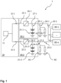
- FIG. 1 is a schematic diagram of a power supply management system 1 according to an exemplary embodiment of the present invention.
- the power supply management system 1 comprises a main power supply unit 10 with a main power supply 11 to supply power to consumer units 30-1, .., 30-n via two power supply lines 27-1, 27-2, each of which is connectable to each of the consumer units 30-1, ... , 30-n via two main power switches 22-1, 22-2, each of which is associated with one of the power supply lines 27-1, 27-2.
- the power supply management system 1 further comprises two supplementary power supply units 20-1, 20-2, each of which comprising a supplementary power supply 21-1, 21-2.
- Each of the supplementary power supplies is connectable to one of the power supply lines 27-1, 27-2 via a respective supplementary power supply switch 25-1, 25-2.
- each of the power supply lines 27-1, 27-2 comprises a converter 26-1, 26-2 disposed between the respective main power supply switch 22-1, 22-2 and the respective branch to the respective supplementary power supply switch 25-1, 25-2.
- the converters 26-1, 26-2 convert the current supplied by the main power supply 11 into a current to be received by the consumer units 30-1, ... , 30-n, e.g. from AC to DC or vice versa or to different voltage levels.
- the converters 26-1, 26-2 may be arranged downstream of the respective main power supply switch 22-1, 22-2 and supplementary power supply switch 25-1, 25-2 in the direction of the power supply to the consumer units 30-1, ..., 30-n to convert both, the current by the main power supply 11 and by the respective supplementary power supply 21-1, 21-2.
- the consumer units 30-1, ..., 30-n further supplementary consumer units A1, B1 are connectable and disconnectable to the power supply line 27-1 by a supplementary consumer switch 24-1 and supplementary consumer units A2, B2 are connectable and disconnectable to the other power supply line 27-2 by a supplementary consumer switch 24-2.
- the consumer units 30-1, .., 30-n a prioritized relative to the supplementary consumer units A1, B1, A2, B2.
- the supplementary consumer units A1, B1, A2, B2 are only connected to the respective power supply lines 27-1, 27-2 as long as the main power supply 11 and/or the respective supplementary power supplies 21-1, 21-2 supply a sufficient amount of power to the consumer units 30-1, ... , 30-n in dependence of a predicted power consumption. Otherwise, at least one of the supplementary consumer switches 24-1, 24-2 disconnects the respective supplementary consumer units A1, B1, A2, B2 from the respective power supply line 27-1, 27-2.
- the main power supply system 10 further comprises a fuse 12-1, 12-2 in each of the power supply lines 27-1, 27-2 disposed between the main power supply 11 and the respective main power supply switch 22-1, 22-2 in each of the power supply lines 27-1, 27-2.
- the fuse is intended to disconnect the main power supply 11 from any component downstream of the respective fuse 12-1, 12-2 in the event of an over voltage or over current in the event of a failure of the respective main power supply switch 22-1, 22-2. Consequently, the fuses 12-1, 12-2 are configured to blow at a current or voltage threshold higher than an upper threshold of the respective main power supply switch 22-1, 22-2. As a result, the fuses 12-1, 12-2 only blow, if the respective main power supply switch 22-1, 22-2 does not function properly.
- the main power supply switches 22-1, 22-2 and the supplementary power supply switches 25-1, 25-2 are configured as normally open switches.
- the consumer switches 23-1, 23-2 and the supplementary consumer switches 24-1, 24-2 are configured as normally closed switches.
- the supplementary power supply switches 25-1, 25-2 or at least one of the supplementary power supply switches 25-1, 25-2 may also be configured as normally closed switches. All of the switches 22-1, 22-2, 23-1, 23-2, 24-1, 24-1, 25-1, 25-2 are arranged as high-side switches.
- Each of the switches 22-1, 22-2, 23-1, 23-2, 24-1, 24-1, 25-1, 25-2 is a so-called smart switch configured to detect a reverse polarity, an over voltage, an under voltage, an over current and/or a temperature exceeding or falling below a predetermined threshold associated with a failure and/or a risk of damaging other components and to open to interrupt the respective power supply line 27-1, 27-2.
- the switches 22-1, 22-2, 23-1, 23-2, 24-1, 24-1, 25-1, 25-2 can detect a reverse polarity and are configured to decide whether a switching is required based one predetermined thresholds.
- the main power supply switches 22-1, 22-2, the consumer switches 23-1, 23-2 and the supplementary consumer switches 24-1, 24-2 are closed to supply the consumer units 30-1, ..., 30n and the supplementary consumer units A1, B1, A2, B2 with power from the main power supply 11.
- the supplementary power supply switches 25-1, 25-2 are opened.
- at least one of the supplementary power supply switches 25-1, 25-2 may be closed during normal operation to allow a power supply in the event of an increased power supply demand by at least one of the consumer units 30-1, ..., 30n.
- At least one supplementary power supply 21-1, 21-2 associated with a respective supplementary power supply switch 25-1, 25-2 may work as a buffer.
- the at least one supplementary power supply 21-1, 21-2 may also be charged by the main power supply 11 in such configuration. If in the present embodiment, for example, an over current is detected by one of the main power supply switches 22-1, 22-2, the respective main power supply switch 22-1, 22-2 opens to disconnect the main power supply 11 from the respective power supply line 27-1, 27-2. To allow further power supply to the consumer units 30-1, ..., 30n, the respective supplementary power supply switches 25-1, 25-2 are closed.
- the supplementary power supply switch 25-1, 25-2 may remain closed.
- the respective supplementary consumer switches 24-1, 24-2 may be opened to disconnect the respective supplementary consumer units A1, B1, A2, B2 from the respective power supply line 27-1, 27-2.
- the respective consumer switch 23-1, 23-2 If the respective consumer switches 23-1, 23-2 detect a further failure downstream of the respective supplementary power supply switches 25-1, 25-2, the respective consumer switch 23-1, 23-2 opens to disconnect the consumer units 30-1, ..., 30n from a respective power supply line 27-1, 27-2 to protect the respective consumer unit 30-1, ..., 30-n against any potential damage by such failure.
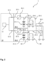
- FIG 2 is a schematic diagram of the power supply management system 1 according to Figure 1 depicting further details with respect to a consumer units 30-1, ..., 30-n of the power supply management system 1.
- Figure 2 only shows consumer unit 30-1.
- the consumer unit 30-1 comprises two consumers C1, C2.
- the range of functions of the two consumers C1, C2 is identical. Accordingly, consumer 1 is redundant to consumer 2 and vice versa.
- Each of the consumers C1, C2 is connectable to one of the power supply lines 27-1, 27-2. As one supply line 27-1, 27-2 and/or one of the consumers C1, C2 may fail, the power supply management system 1 may still provide the same functionalities by the other consumer C1, C2.
- a smart switch for the switches or the fuse described above a smart fuse may be used that provides similar control options with respect to a failure detection but only with a one-time switching capability.
- the smart switches may provide a pre-charge and/or discharge capability. As a resistance when a smart switch is turned on may be very small, a small voltage difference between the two sides of such smart switch may result in a high current spike during the transition. Therefore, a pre-charge capability may be implemented to eliminate or at least reduce the voltage difference before the smart switch is turned on. Further, when the smart switch is turned off, the respective current path is interrupted and energy stored, e.g.
- the smart switch may comprise an electrical circuit as a charge pump to supply a higher voltage level for the smart switch to be turned on.
- the smart switches may further be configured to provide self-testing capabilities.
- such smart switch may comprise an electrical circuit to test whether the current sensing of the smart switch is working properly before the smart switch is turned on.
Landscapes
- Engineering & Computer Science (AREA)
- Business, Economics & Management (AREA)
- Emergency Management (AREA)
- Power Engineering (AREA)
- Mechanical Engineering (AREA)
- Remote Monitoring And Control Of Power-Distribution Networks (AREA)
Description
- The present invention relates to a power supply management system for a vehicle.
- The electrification in the automotive sector has triggered replacements of several vehicle components resulting in novel architectures. For example, many components of commercial vehicles used to rely on compressed air as energy source for control and actuation purposes. A redundant power supply system based on compressed air was implemented for several safety relevant components. Due to the electrification many of these pneumatic components are to be replaced by electrically powered components. In addition, automated driving applications set new requirements for the vehicle systems and, in particular, for safety relevant consumer units.
- With respect to an electric power supply, components of a respective redundant power supply system are protected against an over current or the like by a fuse. Such fuse is, for example, arranged in a power supply line between a power supply unit and a consumer unit. In the event of an over current, blowing of the fuse disconnects the consumer unit from any further power supply. However, blowing of the fuse requires a replacement by a new fuse. Accordingly, a respective replacement is time and cost consuming. In particular, the performance of such vehicle may be limited due to the disconnection until a replacement of the fuse, even if the power supply unit returns to a normal operating state.
-
DE 10 2005 004330 A1 discloses an electrical system for safety-relevant consumers, which includes at least two sub-networks, a first conventional sub-electrical system and a second auxiliary electrical system with the components, which serves to achieve a secure and reliable electrical energy supply for the safety-relevant consumers. The auxiliary electrical system comprises at least four connection paths, via which the safety-relevant consumer can be connected to at least two batteries. -
WO 2009/145678 A1 discloses a switch module comprising at least one switch exhibiting at least two states of operation, provided for connecting at least two conductor segments of an electrical power supply network, the electrical power supply network comprising one or more power sources and one or more electrical loads. One control unit is provided per switch and is operatively coupled to said switch for controlling said states of operation of said switch. - In view of the above, it is an object of the present invention to provide a power management system for a vehicle allowing safe power supply to a consumer unit with reduced efforts and respectively associated disadvantages in response to a failure.
- The object is solved by a power supply management system for a vehicle according to
claim 1. Further aspects of the present invention are subject to the dependent claims. - According to the present invention a power supply management system for a vehicle comprises at least one main power supply unit comprising at least one main power supply, at least one supplementary power supply unit comprising at least one supplementary power supply, at least one consumer unit and at least one power supply line connectable to the at least one consumer unit to supply power from the at least one main power supply and/or the at least one supplementary power supply to the at least one consumer unit. Further, the main power supply and/or the at least one supplementary power supply is/are connectable and disconnectable to the at least one supply line by a main power supply switch and/or supplementary power supply switch, respectively.
- The at least one main power supply unit is intended to supply power to the at least one consumer unit during normal operation of the vehicle. In the event of a complete or at least partial failure of the at least one main supply unit, the at least one supplementary power supply unit is intended to at least partially replace the at least one main supply unit. Each of the at least one main power supply unit and the at least one supplementary power supply comprises at least one main power supply or at least supplementary power supply, respectively. The at least one main power supply unit and the at least one supplementary power supply may comprise further components such as a converter or the like.
- As the main power supply may be connected and disconnected to the at least one power supply line by the main power supply switch, the at least one main power supply may be connected to the at least one power supply line during normal operation. In the event of a failure of the at least one main power supply or any other component of the main power supply unit, the at least one main power supply may be disconnected from the at least one supply line. This allows protection of the at least one consumer unit from any disadvantageous effect due to such failure.
- Similarly, the supplementary power supply may be connected and disconnected to the at least one power supply line by the supplementary power supply switch, the at least one supplementary power supply may be disconnected to the at least one power supply line during normal operation and may be connected to the at least one power supply line on demand, e.g. in the event of a failure of the at least one main power supply or any other component of the at least one main power supply unit.
- With respect to the use of the at least one main power supply switch and/or the at least one supplementary power supply switch, the at least one main power supply and/or the at least one supplementary power supply do not necessarily have to be deactivated in the event of a failure or due to non-operation for an intended power supply but may only be disconnected from the at least one power supply line. Accordingly, the at least one main power supply and/or the at least one supplementary power supply may be kept in active state, even if not connected to the at least one power supply line, to immediately provide a power supply if connected to the at least one power supply line. Furthermore, the functionality of the at least one main power supply and/or the at least one supplementary power supply may be monitored during the active state when disconnect without influencing the at least one consumer unit. In particular with respect to the at least one main power supply, the functionality or recovery after a failure may be monitored. With the at least one main power supply returning to a normal operating state, the at least one main power supply may be reconnected and the at least one supplementary power supply may be disconnected.
- Accordingly, a connection of the at least one main power supply and/or the at least one supplementary power supply to the at least power supply line may be reestablished after a disconnection due to the main power supply switch and/or the supplementary power supply switch without requiring a replacement as in the event of the use of fuses.
- Further, the at least one power supply line comprises at least one consumer switch configured to connect and disconnect the at least consumer unit from any power supply of the at least one main power supply and the at least one supplementary power supply.
- The consumer switch provides a further protection of the consumer unit from any failure by the at least one main power supply and the at least one supplementary power supply. Assuming that the at least main power supply and the at least one supplementary power supply can be connected and disconnected from the at least one power supply line to supply power to the consumer unit by the at least one main power supply switch and/or supplementary power supply switch. In such configuration, the consumer unit can be disconnected from both, the at least one main power supply and the a least one supplementary power supply by the consumer switch independently of any switch state of the at least one main power supply switch and supplementary power supply switch. The consumer switch may thereby provide a further security level.
- In some embodiments, the power supply management system further comprises at least one supplementary consumer unit connectable to the at least one power supply line by a supplementary consumer switch configured to connect and disconnect the at least one supplementary consumer unit to or from the at least one power supply line.
- The at least one supplementary consumer unit may be a unit that may be connectable and disconnectable to the power supply on demand only. Instead, the at least one consumer unit as previously addressed may be a unit directly associated with the power supply line. Preferably, the at least one supplementary consumer unit is only connected to the power supply line, if the energy supply by the at least one main power supply and/or the at least one supplementary power supply supplies sufficient power for the at least one consumer unit and there is remaining power to be supplied to the at least one supplementary consumer unit. With the supplementary consumer unit switch disconnecting the supplementary consumer unit from the at least one power supply line, a power consumption by the at least one supplementary consumer unit with respect to a power required by the at least one consumer unit may be avoided. For example, the at least one consumer unit comprises safety relevant and safety critical functions while the at least one supplementary consumer unit does preferably not provide any safe relevant and safety critical functions. Accordingly, the at least one consumer unit is prioritized. If there is no remaining power for the at least one supplementary consumer unit, the supplementary consumer unit switch does not connect the at least one supplementary consumer unit to the at least one power supply line or disconnects the at least one supplementary consumer unit, if already connected, from the power supply line.
- In some embodiments, at least one of the main power supply switch and the supplementary power supply switch is a normally open switch.
- Accordingly, the main power supply switch has to be activated to connect the at least one main power supply to the at least one power supply line to supply power to the at least one consumer unit. Similarly, the supplementary power supply switch has to be activated to connect the at least one supplementary power supply to the at least one power supply line to supply power to the at least one consumer unit. Therefore, a risk of an unintended connection of the at least one main power supply and/or the at least one supplementary power supply to the at least one power supply line to supply power to the at least one consumer unit may be reduced. As a result, the consumer unit may be protected from any failure of the at least one main power supply and/or the at least one supplementary power supply. Furthermore, an unnecessary power consumption may be avoided.
- In some embodiments, at least one of the consumer switch and the supplementary consumer switch is a normally closed switch.
- Accordingly, the at least one consumer switch has to be deactivated to connect the at least one consumer unit to the at least one power supply line. Similarly, the at least one supplementary consumer unit switch has to be deactivated to connect the at least one supplementary consumer unit to the at least one power supply line. Therefore, a connection of the power supply to the consumer unit and/or supplementary consumer unit is not interrupted by the at least one consumer switch or the at least one supplementary consumer switch, respectively, as long as the at least one consumer switch and/or the at least one supplementary consumer switch is not activated. In other words, a risk of an unintended interruption by the at least one consumer switch and/or the at least one supplementary consumer switch may be reduced.
- In some embodiments, at least one of the main power supply switch, the supplementary power supply switch, the consumer switch and the supplementary consumer switch is a high side switch.
- For example, the at least one consumer switch is disposed between the at least one consumer unit and any of the at least one main power supply and/or the at least supplementary power supply. Similarly, the at least one supplementary consumer switch may be disposed between the at least one supplementary consumer unit and any of the at least one main power supply and/or the at least supplementary power supply. As another example, the main power supply switch may be disposed between the main power supply and the at least one consumer switch, which is disposed between the at least one consumer unit and any of the at least one main power supply and/or the at least supplementary power supply. Similarly, the at least one supplementary power supply switch may be disposed between the supplementary power supply and the at least one consumer switch, which is disposed between the at least one consumer unit and any of the at least one main power supply and/or the at least supplementary power supply. With at least one of the main power supply switch, the supplementary power supply switch, the consumer switch and the supplementary consumer switch being a high side switch, any effect by a failure in advance of the consumer unit may be prohibited from reaching the at least one consumer unit via the power supply line. In particular, the at least one consumer switch as high side switch may separate the at least one consumer unit from any upstream component with respect to the direction of power supply along the power supply line at once. For example, the high side switch is connecting to the voltage supply of the power supply line. Accordingly, the ground of the different components associated with the high side switch are connected together at all times and they are on the same electrical potential.
- In some embodiments, at least one of the main power supply switch, the supplementary power supply switch, the consumer switch and the supplementary consumer switch is a low side switch.
- Similarly to the consumer switch, any low side switch may allow to disconnect a power supply by and for all components at once. However, the influence before the disconnection may run over the at least one consumer unit. For example, the low side switch is connecting to the ground of the power supply line. Accordingly, a lower voltage level than the input voltage level is sufficient to control the low side switch.
- In some embodiments, the power supply management system is configured to switch at least one of the main power supply switch, the supplementary power supply switch, the consumer switch and the supplementary consumer switch in a disconnected state based on a reverse polarity, an over voltage, an under voltage, an over current and/or a temperature exceeding or falling below a predetermined threshold.
- Accordingly, any subsequent component downstream of the at least one of the main power supply switch, the supplementary power supply switch, the consumer switch and the supplementary consumer switch with respect to the direction of power supply may be protected against any negative effect or damage due to a reverse polarity, an over voltage, an under voltage, an over current and/or a temperature exceeding or falling below a predetermined threshold. To detect a reverse polarity, an over voltage, an under voltage, an over current and/or a temperature exceeding or falling below a predetermined threshold and to switch at least one of the at least one main power supply switch, the at least one supplementary power supply switch, the at least one consumer switch and the at least one supplementary consumer switch in a disconnected state accordingly, the power supply management system may comprise a monitoring and control unit.
- Preferably, at least one of the main power supply switch, the supplementary power supply switch, the consumer switch and the supplementary consumer switch is configured to detect a reverse polarity, an over voltage, an under voltage, an over current and/or a temperature exceeding or falling below a predetermined threshold and to switch into a disconnected state based on such detection.
- A switch capable of detecting such failure may be assumed as smart switch. Such smart switch may transmit a respective failure signal to a control unit configured to switch the smart switch accordingly. Alternatively or in addition, the smart switch is capable of processing respective signals within a smart switch processor unit to switch itself. A smart switch as self-switching switch may provide faster reaction times. An additional control unit may function as a redundant security level as the smart switch may fail. Further, the control unit separate from the smart switch may also allow the respective switch being switched due to other events not detectable by the switch itself, like a failure of a downstream component.
- In some embodiments, at least one of the main power supply switch, the supplementary power supply switch, the consumer switch and the supplementary consumer switch is configured to detect a functional state of the at least one consumer unit, the at least one main power supply and/or the at least one supplementary power supply.
- The at least one main power supply switch, the at least one supplementary power supply switch, the at least one consumer switch and/or the at least one supplementary consumer switch may therefore be configured to receive functional state information of the at least one consumer unit, the at least one main power supply and/or the at least one supplementary power supply. The functional state information may be processed by the at least one supplementary power supply switch, the at least one consumer switch and/or the at least one supplementary consumer switch and/or transmitted to a control unit. As a consequence of a detected functional state deviating from a predetermined functional state, the at least one main power supply switch, the at least one supplementary power supply switch, the at least one consumer switch and/or the at least one supplementary consumer switch may switch itself or may be switched by the control unit in a disconnected state. Alternatively or in addition, the at least one main power supply switch, the at least one supplementary power supply switch, the at least one consumer switch and/or the at least one supplementary consumer switch and/or the control unit may deactivate the at least one consumer unit, the at least one main power supply and/or the at least one supplementary power supply associated with a respective failure or affected by a result of such failure. Thereby damages of affected components and/or an unnecessary power consumption may be avoided.
- A respective detection may be performed continuously, periodically or based on predetermined events. A predetermined event may be an initiation of a detection procedure, e.g. by an operator's input or a particular program routine, a start of the vehicle and/or a change of an operating mode of the vehicle. The predetermined events may be adaptable in dependence of an operating mode of the vehicle, e.g. when changing in an autonomous driving mode.
- Preferably, the detection of the functional state comprises at least a detection of the functional state of safety-critical components or functions.
- Safety critical components or functions are mandatory for operating a vehicle. If any of the critical components or functions is not in a predetermined functional state a safety critical failure is assumed and operation of the vehicle has to be stopped. A safety-critical component may be the at least one consumer unit and/or a functional group associated with the at least one consumer unit, such as a braking device controlled a braking unit as consumer unit.
- In some embodiments, at least one of the main power supply switch, the supplementary power supply switch, the consumer switch and the supplementary consumer switch is configured to provide a self-fault diagnosis.
- Accordingly, the at least one main power supply switch, the at least one supplementary power supply switch, the at least one consumer switch and/or the at least one supplementary consumer switch may not only be configured to detect the functional state of other components or at least a subsequent effect of a failure of such components. Alternatively or in addition, the at least one main power supply switch, the at least one supplementary power supply switch, the at least one consumer switch and/or the at least one supplementary consumer switch comprises a self-fault-diagnosis capability to provide an information of the functional state as such independent of any functional state of any component of the overall power supply management system. Such switch may deactivate itself in the event of a detected failure and/or transmits such information to a control unit to deactivate the respective switch accordingly. Consequences of a deactivation may be dependent on the respective switch being a normally open or normally closed switch. In the event of a normally open switch, the function associated with a respective connection by the respective switch may be no longer available due to deactivation of the switch. Therefore, the control unit may provide a warning signal and/or may cause the vehicle to stop. In the event of a normally closed switch, the function associated with a respective connection by the respective switch may no longer be disconnected due to deactivation of the switch but only deactivated by controlling the respective component.
- In some embodiments, the at least one consumer unit comprises at least two consumers, each of which is connected or connectable by a respective consumer switch to a respective power supply line associated with a different main power supply and/or a different supplementary power supply.
- As the at least one main power supply and/or the at least one supplementary power supply may fail, at least one of the at least two consumers may still be operable as being independent of the at least one main power supply and/or the at least one supplementary power supply. In one example, each of the at least two consumers is associated with at least one different supplementary power supply. A complete failure of all functions provided by the at least two consumers due to a failure of one supplementary power supply may therefore be avoided. Even though the at least two consumers may be connectable and disconnectable to different supplementary power supplies, the at least two consumers may be connectable and disconnectable to the same main power supply.
- Preferably, at least one of the at least two consumers of the at least one consumer unit comprises at least partially redundant functions with respect to at least another one of the at least two consumers of the at least one consumer unit.
- Accordingly, the one consumer unit is at least partially redundant to the other consumer unit.
- Preferably, the at least one of the at least two consumers of the at least one consumer unit comprises at least redundant safety-critical functions with respect to the at least one other of the at least two consumers of the at least one consumer unit.
- Therefore, at least safety-critical functions may still be performed by the one consumer in the event of a failure of the other consumer or the at least main power supply and/or the at least one supplementary power supply associated with the other consumer.
- In some embodiments, the at least one power supply line comprises at least one fuse.
- In the event of a failure of the at least one main power supply switch, the at least one supplementary power supply switch, the at least one consumer switch and/or the at least one supplementary consumer switch, the at least one fuse can still provide a redundant safety level. The at least one fuse may be arranged in association with a respective one of the at least one main power supply switch, the at least one supplementary power supply switch, the at least one consumer switch and/or the at least one supplementary consumer switch to provide the additional safety level for the respectively, associated switch. Accordingly the threshold for blowing the at least one fuse may be set to a value above an upper disconnecting threshold of the respective switch to allow the switch to disconnect first before unnecessarily blowing the fuse. In other words, the threshold for blowing is configured in such way that in case of a failure the respective switch would disconnect prior to the fuse. But if the switch has a failure and does not disconnect in this case, the disconnection will then be realized by the fuse. The power supply management system may comprise such fuse for any or at least one of at least one main power supply switch, the at least one supplementary power supply switch, the at least one consumer switch and/or the at least one supplementary consumer switch
- Further advantages, aspects and details of the invention are subject to the claims, the following description of preferred embodiments applying the principles of the invention, and drawings. In particular:
-
Figure 1 is a schematic diagram of a power supply management system according to an exemplary embodiment of the present invention; and -
Figure 2 is a schematic diagram of the power supply management system according toFigure 1 depicting further details with respect to a consumer unit of the power supply management system. -
Figure 1 is a schematic diagram of a powersupply management system 1 according to an exemplary embodiment of the present invention. The powersupply management system 1 comprises a mainpower supply unit 10 with amain power supply 11 to supply power to consumer units 30-1, .., 30-n via two power supply lines 27-1, 27-2, each of which is connectable to each of the consumer units 30-1, ... , 30-n via two main power switches 22-1, 22-2, each of which is associated with one of the power supply lines 27-1, 27-2. The powersupply management system 1 further comprises two supplementary power supply units 20-1, 20-2, each of which comprising a supplementary power supply 21-1, 21-2. Each of the supplementary power supplies is connectable to one of the power supply lines 27-1, 27-2 via a respective supplementary power supply switch 25-1, 25-2. Further, each of the power supply lines 27-1, 27-2 comprises a converter 26-1, 26-2 disposed between the respective main power supply switch 22-1, 22-2 and the respective branch to the respective supplementary power supply switch 25-1, 25-2. The converters 26-1, 26-2 convert the current supplied by themain power supply 11 into a current to be received by the consumer units 30-1, ... , 30-n, e.g. from AC to DC or vice versa or to different voltage levels. In alternative embodiments the converters 26-1, 26-2 may be arranged downstream of the respective main power supply switch 22-1, 22-2 and supplementary power supply switch 25-1, 25-2 in the direction of the power supply to the consumer units 30-1, ..., 30-n to convert both, the current by themain power supply 11 and by the respective supplementary power supply 21-1, 21-2. Next to the consumer units 30-1, ..., 30-n further supplementary consumer units A1, B1 are connectable and disconnectable to the power supply line 27-1 by a supplementary consumer switch 24-1 and supplementary consumer units A2, B2 are connectable and disconnectable to the other power supply line 27-2 by a supplementary consumer switch 24-2. The consumer units 30-1, .., 30-n a prioritized relative to the supplementary consumer units A1, B1, A2, B2. That is, the supplementary consumer units A1, B1, A2, B2 are only connected to the respective power supply lines 27-1, 27-2 as long as themain power supply 11 and/or the respective supplementary power supplies 21-1, 21-2 supply a sufficient amount of power to the consumer units 30-1, ... , 30-n in dependence of a predicted power consumption. Otherwise, at least one of the supplementary consumer switches 24-1, 24-2 disconnects the respective supplementary consumer units A1, B1, A2, B2 from the respective power supply line 27-1, 27-2. The mainpower supply system 10 further comprises a fuse 12-1, 12-2 in each of the power supply lines 27-1, 27-2 disposed between themain power supply 11 and the respective main power supply switch 22-1, 22-2 in each of the power supply lines 27-1, 27-2. The fuse is intended to disconnect themain power supply 11 from any component downstream of the respective fuse 12-1, 12-2 in the event of an over voltage or over current in the event of a failure of the respective main power supply switch 22-1, 22-2. Consequently, the fuses 12-1, 12-2 are configured to blow at a current or voltage threshold higher than an upper threshold of the respective main power supply switch 22-1, 22-2. As a result, the fuses 12-1, 12-2 only blow, if the respective main power supply switch 22-1, 22-2 does not function properly. - According to the exemplary embodiment, the main power supply switches 22-1, 22-2 and the supplementary power supply switches 25-1, 25-2 are configured as normally open switches. The consumer switches 23-1, 23-2 and the supplementary consumer switches 24-1, 24-2 are configured as normally closed switches. In alternative embodiments, the supplementary power supply switches 25-1, 25-2 or at least one of the supplementary power supply switches 25-1, 25-2 may also be configured as normally closed switches. All of the switches 22-1, 22-2, 23-1, 23-2, 24-1, 24-1, 25-1, 25-2 are arranged as high-side switches. Each of the switches 22-1, 22-2, 23-1, 23-2, 24-1, 24-1, 25-1, 25-2 is a so-called smart switch configured to detect a reverse polarity, an over voltage, an under voltage, an over current and/or a temperature exceeding or falling below a predetermined threshold associated with a failure and/or a risk of damaging other components and to open to interrupt the respective power supply line 27-1, 27-2. For example, the switches 22-1, 22-2, 23-1, 23-2, 24-1, 24-1, 25-1, 25-2 can detect a reverse polarity and are configured to decide whether a switching is required based one predetermined thresholds.
- Next, a description is given to the operation of the power
supply management system 1 according to the present embodiment. During a normal driving operation of a vehicle comprising the powersupply management system 1 the main power supply switches 22-1, 22-2, the consumer switches 23-1, 23-2 and the supplementary consumer switches 24-1, 24-2 are closed to supply the consumer units 30-1, ..., 30n and the supplementary consumer units A1, B1, A2, B2 with power from themain power supply 11. The supplementary power supply switches 25-1, 25-2 are opened. In alternative embodiments, at least one of the supplementary power supply switches 25-1, 25-2 may be closed during normal operation to allow a power supply in the event of an increased power supply demand by at least one of the consumer units 30-1, ..., 30n. Accordingly, at least one supplementary power supply 21-1, 21-2 associated with a respective supplementary power supply switch 25-1, 25-2 may work as a buffer. The at least one supplementary power supply 21-1, 21-2 may also be charged by themain power supply 11 in such configuration. If in the present embodiment, for example, an over current is detected by one of the main power supply switches 22-1, 22-2, the respective main power supply switch 22-1, 22-2 opens to disconnect themain power supply 11 from the respective power supply line 27-1, 27-2. To allow further power supply to the consumer units 30-1, ..., 30n, the respective supplementary power supply switches 25-1, 25-2 are closed. In the alternative embodiment with at least one of the supplementary power supply switches 25-1, 25-2 being a normally closed switch, the supplementary power supply switch 25-1, 25-2 may remain closed. As the maximum power that can be provided by the respective supplementary power supplies 21-1, 21-2 may be limited and therefore only sufficient to cover the power consumption of the consumer units 30-1, ..., 30n, the respective supplementary consumer switches 24-1, 24-2 may be opened to disconnect the respective supplementary consumer units A1, B1, A2, B2 from the respective power supply line 27-1, 27-2. If the respective consumer switches 23-1, 23-2 detect a further failure downstream of the respective supplementary power supply switches 25-1, 25-2, the respective consumer switch 23-1, 23-2 opens to disconnect the consumer units 30-1, ..., 30n from a respective power supply line 27-1, 27-2 to protect the respective consumer unit 30-1, ..., 30-n against any potential damage by such failure. -
Figure 2 is a schematic diagram of the powersupply management system 1 according toFigure 1 depicting further details with respect to a consumer units 30-1, ..., 30-n of the powersupply management system 1. To simplify the representation,Figure 2 only shows consumer unit 30-1. The consumer unit 30-1 comprises two consumers C1, C2. Here, the range of functions of the two consumers C1, C2 is identical. Accordingly,consumer 1 is redundant to consumer 2 and vice versa. Each of the consumers C1, C2 is connectable to one of the power supply lines 27-1, 27-2. As one supply line 27-1, 27-2 and/or one of the consumers C1, C2 may fail, the powersupply management system 1 may still provide the same functionalities by the other consumer C1, C2. - The invention has been described in with respect to an exemplary embodiment. However, the invention is not limited to the exemplary embodiment. In particular, instead of a smart switch for the switches or the fuse described above, a smart fuse may be used that provides similar control options with respect to a failure detection but only with a one-time switching capability. Further, the smart switches may provide a pre-charge and/or discharge capability. As a resistance when a smart switch is turned on may be very small, a small voltage difference between the two sides of such smart switch may result in a high current spike during the transition. Therefore, a pre-charge capability may be implemented to eliminate or at least reduce the voltage difference before the smart switch is turned on. Further, when the smart switch is turned off, the respective current path is interrupted and energy stored, e.g. in capacitors, downstream of the smart switch may only be slowly dissipated. To accelerate the dissipation, a discharge capability may be implemented in the smart switch. As another example, the smart switch may comprise an electrical circuit as a charge pump to supply a higher voltage level for the smart switch to be turned on. The smart switches may further be configured to provide self-testing capabilities. For example, such smart switch may comprise an electrical circuit to test whether the current sensing of the smart switch is working properly before the smart switch is turned on.
-
- 1
- power supply management system
- 10
- main power supply unit
- 11
- main power supply
- 12-1, 12-2
- fuse
- 20-1, 20-2
- supplementary power supply unit
- 21-1, 21-2
- supplementary power supply
- 22-1, 22-2
- main power supply switch
- 23-1, 23-2
- consumer switch
- 24-1, 24-2
- supplementary consumer switch
- 25-1, 25-2
- supplementary power supply switch
- 26-1, 26-2
- converter
- 27-1, 27-2
- power supply line
- 30-1, ..., 30-n
- consumer unit
- A1, A2, B1, B2
- supplementary consumer unit
- C1, C2
- (redundant) consumer
Claims (15)
- A power supply management system (1) for a vehicle comprising:at least one main power supply unit (10) comprising at least one main power supply (11),at least one supplementary power supply unit (20-1, 20-2) comprising at least one supplementary power supply (21-1. 21-2),at least one consumer unit (30-1, ..., 30-n) andat least one power supply line (27-1, 27-2) connectable to the at least one consumer unit (30-1, ..., 30-n) to supply power from the at least one main power supply (11) and/or the at least one supplementary power supply (21-1, 21-2) to the at least one consumer unit (30-1, ..., 30-n),wherein the main power supply (11) and the at least one supplementary power supply (21-1, 21-2) are connectable and disconnectable to the at least one supply line (27-1, 27-2) by a main power supply switch (22-1, 22-2) and a supplementary power supply switch (25-1, 25-2), respectively, and whereinthe at least one power supply line (27-1, 27-2) comprises at least one consumer switch (23-1, 23-2) configured to connect and disconnect the at least consumer unit (30-1, ..., 30-n) from any power supply of the at least one main power supply (11) and the at least one supplementary power supply (21-1, 21-2).
- The power supply management system (1) according to claim 1, wherein the power supply management system (1) further comprises at least one supplementary consumer unit (A1, A2, B1, B2) connectable to the at least one power supply line (27-1, 27-2) by a supplementary consumer switch (24-1, 24-2) configured to connect and disconnect the at least one supplementary consumer unit (A1, A2, B1, B2) to or from the at least one power supply line (27-1, 27-2).
- The power supply management system (1) according to claim 1 or 2, wherein at least one of the main power supply switch (22-1, 22-2) and the supplementary power supply switch (25-1, 25-2) is a normally open switch.
- The power supply management system (1) according to any of the preceding claims, wherein at least one of the consumer switch (23-1, 23-2) and the supplementary consumer switch (24-1, 24-2) is a normally closed switch.
- The power supply management system (1) according to any of the preceding claims, wherein at least one of the main power supply switch (22-1, 22-2), the supplementary power supply switch (25-1, 25-2), the consumer switch (23-1, 23-2) and the supplementary consumer switch (24-1, 24-2) is a high side switch.
- The power supply management system (1) according to any of the preceding claims, wherein at least one of the main power supply switch (22-1, 22-2), the supplementary power supply switch (25-1, 25-2), the consumer switch (23-1, 23-2) and the supplementary consumer switch (24-1, 24-2) is a low side switch.
- The power supply management system (1) according to any of the preceding claims, wherein the power supply management system (1) is configured to switch at least one of the main power supply switch (22-1, 22-2), the supplementary power supply switch (25-1, 25-2), the consumer switch (23-1, 23-2) and the supplementary consumer switch (24-1, 24-2) in a disconnected state based on a reverse polarity, an over voltage, an under voltage, an over current and/or a temperature exceeding or falling below a predetermined threshold.
- The power supply management system (1) according to claim 7, wherein at least one of the main power supply switch (22-1, 22-2), the supplementary power supply switch (25-1, 25-2), the consumer switch (23-1, 23-2) and the supplementary consumer switch (24-1, 24-2) is configured to detect a reverse polarity, an over voltage, an under voltage, an over current and/or a temperature exceeding or falling below a predetermined threshold and to switch into a disconnected state based on such detection.
- The power supply management system (1) according to any of the preceding claims, wherein at least one of the main power supply switch (22-1, 22-2), the supplementary power supply switch (25-1, 25-2), the consumer switch (23-1, 23-2) and the supplementary consumer switch (24-1, 24-2) is configured to detect a functional state of the at least one consumer unit (30-1, ..., n), the at least one main power supply (11) and/or the at least one supplementary power supply (21-1, 21-2).
- The power supply management system (1) according to claim 9, wherein the detection of the functional state comprises at least a detection of the functional state of safety-critical components or functions.
- The power supply management system (1) according to any of the preceding claims, wherein at least one of the main power supply switch (22-1, 22-2), the supplementary power supply switch (25-1, 25-2), the consumer switch (23-1, 23-2) and the supplementary consumer switch (24-1, 24-2) is configured to provide a self-fault diagnosis.
- The power management supply system (1) according to any of the preceding claims, wherein the at least one consumer unit (30-1, ..., 30-n) comprises at least two consumers (C1, C2), each of which is connected or connectable by a respective consumer switch (23-1, 23-2) to a respective power supply line (27-1, 27-2) associated with a different main power supply (11) and/or a different supplementary power supply (21-1, 21-2).
- The power management supply system (1) according to claim 12, wherein at least one of the at least two consumers (C1, C2) of the at least one consumer unit (30-1, ..., 30-n) comprises at least partially redundant functions with respect to at least another one of the at least two consumers (C1, C2) of the at least one consumer unit (30-1, ..., 30-n).
- The power management supply system (1) according to claim 13, wherein the at least one of the at least two consumers (C1, C2) of the at least one consumer unit (30-1, ..., 30-n) comprises at least redundant safety-critical functions with respect to the at least one other of the at least two consumers (C1, C2) of the at least one consumer unit (30-1, ..., 30-n).
- The power management supply system (1) according to any of the preceding claims, wherein the at least one power supply line (27-1, 27-2) comprises at least one fuse (12-1, 12-2).
Priority Applications (4)
| Application Number | Priority Date | Filing Date | Title |
|---|---|---|---|
| EP21185133.2A EP4119400B1 (en) | 2021-07-12 | 2021-07-12 | Power supply management system for a vehicle |
| CN202280049506.4A CN117693447A (en) | 2021-07-12 | 2022-06-29 | Power management system for vehicles |
| US18/566,133 US12479379B2 (en) | 2021-07-12 | 2022-06-29 | Power supply management system for a vehicle |
| PCT/EP2022/067882 WO2023285145A1 (en) | 2021-07-12 | 2022-06-29 | Power supply management system for a vehicle |
Applications Claiming Priority (1)
| Application Number | Priority Date | Filing Date | Title |
|---|---|---|---|
| EP21185133.2A EP4119400B1 (en) | 2021-07-12 | 2021-07-12 | Power supply management system for a vehicle |
Publications (2)
| Publication Number | Publication Date |
|---|---|
| EP4119400A1 EP4119400A1 (en) | 2023-01-18 |
| EP4119400B1 true EP4119400B1 (en) | 2025-04-23 |
Family
ID=76890925
Family Applications (1)
| Application Number | Title | Priority Date | Filing Date |
|---|---|---|---|
| EP21185133.2A Active EP4119400B1 (en) | 2021-07-12 | 2021-07-12 | Power supply management system for a vehicle |
Country Status (4)
| Country | Link |
|---|---|
| US (1) | US12479379B2 (en) |
| EP (1) | EP4119400B1 (en) |
| CN (1) | CN117693447A (en) |
| WO (1) | WO2023285145A1 (en) |
Citations (6)
| Publication number | Priority date | Publication date | Assignee | Title |
|---|---|---|---|---|
| DE102005004330A1 (en) | 2005-01-31 | 2006-08-10 | Robert Bosch Gmbh | On-board network for safety-relevant consumers |
| US7830120B2 (en) | 2007-09-18 | 2010-11-09 | Nexergy, Inc. | Low side N-channel FET protection circuit |
| US20130234504A1 (en) | 2012-03-12 | 2013-09-12 | Denso Corporation | Power supply system |
| JP2015140094A (en) | 2014-01-29 | 2015-08-03 | 三菱電機株式会社 | In-vehicle electronic control unit |
| CN106896755B (en) | 2015-12-18 | 2020-01-14 | 联创汽车电子有限公司 | Load driving circuit for single-low end control of vehicle |
| DE102011000490B4 (en) | 2010-02-03 | 2020-08-06 | Denso Corporation | Vehicle-based power supply with a generator that is capable of generating regenerative power |
Family Cites Families (6)
| Publication number | Priority date | Publication date | Assignee | Title |
|---|---|---|---|---|
| DE19755050C2 (en) * | 1997-12-11 | 2001-10-18 | Bosch Gmbh Robert | Device for energy supply in a motor vehicle electrical system |
| FR2808630B1 (en) | 2000-04-13 | 2002-10-25 | Peugeot Citroen Automobiles Sa | MULTI-VOLTAGE ELECTRICAL SUPPLY CIRCUIT FOR MOTOR VEHICLE |
| DE10251589A1 (en) * | 2002-11-06 | 2004-05-19 | Robert Bosch Gmbh | On-board electrical system with increased availability requirement has load supplied with supply voltage via at least two different supply paths decoupled from each other by decoupling arrangement |
| WO2009145678A1 (en) * | 2008-05-26 | 2009-12-03 | Volvo Technology Corporation | Switch module for a power supply network and power supply network comprising at least one switch module |
| DE102017222192A1 (en) * | 2017-12-07 | 2019-06-13 | Audi Ag | HV battery assembly for a motor vehicle, electrical system, motor vehicle and method for controlling a HV battery assembly |
| JP7327362B2 (en) * | 2020-11-26 | 2023-08-16 | 株式会社オートネットワーク技術研究所 | In-vehicle backup control device and in-vehicle backup device |
-
2021
- 2021-07-12 EP EP21185133.2A patent/EP4119400B1/en active Active
-
2022
- 2022-06-29 CN CN202280049506.4A patent/CN117693447A/en active Pending
- 2022-06-29 WO PCT/EP2022/067882 patent/WO2023285145A1/en not_active Ceased
- 2022-06-29 US US18/566,133 patent/US12479379B2/en active Active
Patent Citations (6)
| Publication number | Priority date | Publication date | Assignee | Title |
|---|---|---|---|---|
| DE102005004330A1 (en) | 2005-01-31 | 2006-08-10 | Robert Bosch Gmbh | On-board network for safety-relevant consumers |
| US7830120B2 (en) | 2007-09-18 | 2010-11-09 | Nexergy, Inc. | Low side N-channel FET protection circuit |
| DE102011000490B4 (en) | 2010-02-03 | 2020-08-06 | Denso Corporation | Vehicle-based power supply with a generator that is capable of generating regenerative power |
| US20130234504A1 (en) | 2012-03-12 | 2013-09-12 | Denso Corporation | Power supply system |
| JP2015140094A (en) | 2014-01-29 | 2015-08-03 | 三菱電機株式会社 | In-vehicle electronic control unit |
| CN106896755B (en) | 2015-12-18 | 2020-01-14 | 联创汽车电子有限公司 | Load driving circuit for single-low end control of vehicle |
Non-Patent Citations (4)
| Title |
|---|
| ANONYMOUS: "Product brief - HITFET - The ultimate design flexibility", INFINEON, 1 July 2018 (2018-07-01), XP093364077, Retrieved from the Internet <URL:https://www.infineon.com/assets/row/public/documents/10/45/infineon-hitfet-pb-pb-en.pdf?fileId=5546d46264a8de7e0164d1747eb97fb8> |
| ANONYMOUS: "PROFET Smart High-Side Power Switches", INFINEON, 1 September 2011 (2011-09-01), XP093364073 |
| D7: "Fachkunde Kraftfahrzeugtechnik, 30. Auflage", 2013, VERLAG EUROPA-LEHRMITTEL, ISBN: 978-3-8085-2240-0, pages: 584-587, 606-607 |
| HUANG ARTHUR, ROTH EMILY: "Basics of Power Switches", TEXAS INSTRUMENTS, 1 April 2019 (2019-04-01), XP093364083, Retrieved from the Internet <URL:https://www.ti.com/lit/an/slva927a/slva927a.pdf?ts=1770641205755&ref_url=https%253A%252F%252Fwww.ti.com%252Fproduct%252FLM66100%253Fqgpn%253Dlm66100> |
Also Published As
| Publication number | Publication date |
|---|---|
| US12479379B2 (en) | 2025-11-25 |
| WO2023285145A1 (en) | 2023-01-19 |
| CN117693447A (en) | 2024-03-12 |
| US20240246499A1 (en) | 2024-07-25 |
| EP4119400A1 (en) | 2023-01-18 |
Similar Documents
| Publication | Publication Date | Title |
|---|---|---|
| EP3739349B1 (en) | Fault tolerant fail-safe link comprising parallel branches | |
| US10951022B2 (en) | Current distributor and protection system for a vehicle | |
| US20170080883A1 (en) | Automotive power unit | |
| US10838474B2 (en) | Electric power supply system | |
| WO2018163751A1 (en) | In-vehicle power supply unit control device and in-vehicle power supply device | |
| US11077809B2 (en) | Power supply unit for a utility vehicle and method for operating a power supply unit for a utility vehicle | |
| EP2850717B1 (en) | Elevator backup power supply | |
| JP2014183700A (en) | Electric car | |
| US20120249075A1 (en) | Secondary battery voltage detecting system | |
| US11043826B2 (en) | Charge/discharge control circuit and battery device including the same | |
| CN110850329A (en) | Method for diagnosing switchgear in a motor vehicle | |
| CN105229885B (en) | Power supply control device and programmable logic controller | |
| KR20180115239A (en) | Safety monitoring unit | |
| US6236553B1 (en) | Safety relay | |
| EP4119400B1 (en) | Power supply management system for a vehicle | |
| JP5951524B2 (en) | Power supply | |
| CN117461232A (en) | circuit breaker | |
| US20250047090A1 (en) | Fuse Circuit Assembly for An Energy System and Energy System | |
| US20240275264A1 (en) | Circuit arrangement and electrical system | |
| US7719809B2 (en) | Method and apparatus for distributing electrical power | |
| EP4124512B1 (en) | Energy supply module and energy supply management system | |
| JP2002112470A (en) | Off-line ups system | |
| US20240308452A1 (en) | Power Supply Management System for a Vehicle, Method for Operating the Power Management System and Computer Program Product for Carrying Out the Method | |
| US12172590B2 (en) | Vehicle power distribution circuit and vehicle power system | |
| US20240356476A1 (en) | Power supply circuit in an inverter for driving an electrical machine, method of operating the power supply circuit and safety control device |
Legal Events
| Date | Code | Title | Description |
|---|---|---|---|
| PUAI | Public reference made under article 153(3) epc to a published international application that has entered the european phase |
Free format text: ORIGINAL CODE: 0009012 |
|
| STAA | Information on the status of an ep patent application or granted ep patent |
Free format text: STATUS: THE APPLICATION HAS BEEN PUBLISHED |
|
| AK | Designated contracting states |
Kind code of ref document: A1 Designated state(s): AL AT BE BG CH CY CZ DE DK EE ES FI FR GB GR HR HU IE IS IT LI LT LU LV MC MK MT NL NO PL PT RO RS SE SI SK SM TR |
|
| STAA | Information on the status of an ep patent application or granted ep patent |
Free format text: STATUS: REQUEST FOR EXAMINATION WAS MADE |
|
| 17P | Request for examination filed |
Effective date: 20230718 |
|
| RBV | Designated contracting states (corrected) |
Designated state(s): AL AT BE BG CH CY CZ DE DK EE ES FI FR GB GR HR HU IE IS IT LI LT LU LV MC MK MT NL NO PL PT RO RS SE SI SK SM TR |
|
| RAP3 | Party data changed (applicant data changed or rights of an application transferred) |
Owner name: KNORR-BREMSE SYSTEME FUER NUTZFAHRZEUGE GMBH |
|
| GRAP | Despatch of communication of intention to grant a patent |
Free format text: ORIGINAL CODE: EPIDOSNIGR1 |
|
| STAA | Information on the status of an ep patent application or granted ep patent |
Free format text: STATUS: GRANT OF PATENT IS INTENDED |
|
| INTG | Intention to grant announced |
Effective date: 20241213 |
|
| GRAS | Grant fee paid |
Free format text: ORIGINAL CODE: EPIDOSNIGR3 |
|
| GRAA | (expected) grant |
Free format text: ORIGINAL CODE: 0009210 |
|
| STAA | Information on the status of an ep patent application or granted ep patent |
Free format text: STATUS: THE PATENT HAS BEEN GRANTED |
|
| P01 | Opt-out of the competence of the unified patent court (upc) registered |
Free format text: CASE NUMBER: APP_10279/2025 Effective date: 20250228 |
|
| AK | Designated contracting states |
Kind code of ref document: B1 Designated state(s): AL AT BE BG CH CY CZ DE DK EE ES FI FR GB GR HR HU IE IS IT LI LT LU LV MC MK MT NL NO PL PT RO RS SE SI SK SM TR |
|
| REG | Reference to a national code |
Ref country code: GB Ref legal event code: FG4D |
|
| REG | Reference to a national code |
Ref country code: CH Ref legal event code: EP |
|
| REG | Reference to a national code |
Ref country code: DE Ref legal event code: R096 Ref document number: 602021029488 Country of ref document: DE |
|
| REG | Reference to a national code |
Ref country code: IE Ref legal event code: FG4D |
|
| REG | Reference to a national code |
Ref country code: SE Ref legal event code: TRGR |
|
| REG | Reference to a national code |
Ref country code: NL Ref legal event code: MP Effective date: 20250423 |
|
| PG25 | Lapsed in a contracting state [announced via postgrant information from national office to epo] |
Ref country code: NL Free format text: LAPSE BECAUSE OF FAILURE TO SUBMIT A TRANSLATION OF THE DESCRIPTION OR TO PAY THE FEE WITHIN THE PRESCRIBED TIME-LIMIT Effective date: 20250423 |
|
| REG | Reference to a national code |
Ref country code: AT Ref legal event code: MK05 Ref document number: 1787490 Country of ref document: AT Kind code of ref document: T Effective date: 20250423 |
|
| PG25 | Lapsed in a contracting state [announced via postgrant information from national office to epo] |
Ref country code: PT Free format text: LAPSE BECAUSE OF FAILURE TO SUBMIT A TRANSLATION OF THE DESCRIPTION OR TO PAY THE FEE WITHIN THE PRESCRIBED TIME-LIMIT Effective date: 20250825 Ref country code: ES Free format text: LAPSE BECAUSE OF FAILURE TO SUBMIT A TRANSLATION OF THE DESCRIPTION OR TO PAY THE FEE WITHIN THE PRESCRIBED TIME-LIMIT Effective date: 20250423 Ref country code: FI Free format text: LAPSE BECAUSE OF FAILURE TO SUBMIT A TRANSLATION OF THE DESCRIPTION OR TO PAY THE FEE WITHIN THE PRESCRIBED TIME-LIMIT Effective date: 20250423 |
|
| PGFP | Annual fee paid to national office [announced via postgrant information from national office to epo] |
Ref country code: DE Payment date: 20250724 Year of fee payment: 5 |
|
| REG | Reference to a national code |
Ref country code: LT Ref legal event code: MG9D |
|
| PG25 | Lapsed in a contracting state [announced via postgrant information from national office to epo] |
Ref country code: NO Free format text: LAPSE BECAUSE OF FAILURE TO SUBMIT A TRANSLATION OF THE DESCRIPTION OR TO PAY THE FEE WITHIN THE PRESCRIBED TIME-LIMIT Effective date: 20250723 Ref country code: GR Free format text: LAPSE BECAUSE OF FAILURE TO SUBMIT A TRANSLATION OF THE DESCRIPTION OR TO PAY THE FEE WITHIN THE PRESCRIBED TIME-LIMIT Effective date: 20250724 |
|
| PG25 | Lapsed in a contracting state [announced via postgrant information from national office to epo] |
Ref country code: PL Free format text: LAPSE BECAUSE OF FAILURE TO SUBMIT A TRANSLATION OF THE DESCRIPTION OR TO PAY THE FEE WITHIN THE PRESCRIBED TIME-LIMIT Effective date: 20250423 |
|
| PG25 | Lapsed in a contracting state [announced via postgrant information from national office to epo] |
Ref country code: BG Free format text: LAPSE BECAUSE OF FAILURE TO SUBMIT A TRANSLATION OF THE DESCRIPTION OR TO PAY THE FEE WITHIN THE PRESCRIBED TIME-LIMIT Effective date: 20250423 |
|
| PGFP | Annual fee paid to national office [announced via postgrant information from national office to epo] |
Ref country code: GB Payment date: 20250722 Year of fee payment: 5 |
|
| PG25 | Lapsed in a contracting state [announced via postgrant information from national office to epo] |
Ref country code: HR Free format text: LAPSE BECAUSE OF FAILURE TO SUBMIT A TRANSLATION OF THE DESCRIPTION OR TO PAY THE FEE WITHIN THE PRESCRIBED TIME-LIMIT Effective date: 20250423 |
|
| PG25 | Lapsed in a contracting state [announced via postgrant information from national office to epo] |
Ref country code: AT Free format text: LAPSE BECAUSE OF FAILURE TO SUBMIT A TRANSLATION OF THE DESCRIPTION OR TO PAY THE FEE WITHIN THE PRESCRIBED TIME-LIMIT Effective date: 20250423 |
|
| PGFP | Annual fee paid to national office [announced via postgrant information from national office to epo] |
Ref country code: FR Payment date: 20250724 Year of fee payment: 5 |
|
| PGFP | Annual fee paid to national office [announced via postgrant information from national office to epo] |
Ref country code: SE Payment date: 20250723 Year of fee payment: 5 |
|
| PG25 | Lapsed in a contracting state [announced via postgrant information from national office to epo] |
Ref country code: RS Free format text: LAPSE BECAUSE OF FAILURE TO SUBMIT A TRANSLATION OF THE DESCRIPTION OR TO PAY THE FEE WITHIN THE PRESCRIBED TIME-LIMIT Effective date: 20250723 |
|
| PG25 | Lapsed in a contracting state [announced via postgrant information from national office to epo] |
Ref country code: IS Free format text: LAPSE BECAUSE OF FAILURE TO SUBMIT A TRANSLATION OF THE DESCRIPTION OR TO PAY THE FEE WITHIN THE PRESCRIBED TIME-LIMIT Effective date: 20250823 |
|
| PG25 | Lapsed in a contracting state [announced via postgrant information from national office to epo] |
Ref country code: LV Free format text: LAPSE BECAUSE OF FAILURE TO SUBMIT A TRANSLATION OF THE DESCRIPTION OR TO PAY THE FEE WITHIN THE PRESCRIBED TIME-LIMIT Effective date: 20250423 |
|
| PG25 | Lapsed in a contracting state [announced via postgrant information from national office to epo] |
Ref country code: SM Free format text: LAPSE BECAUSE OF FAILURE TO SUBMIT A TRANSLATION OF THE DESCRIPTION OR TO PAY THE FEE WITHIN THE PRESCRIBED TIME-LIMIT Effective date: 20250423 Ref country code: DK Free format text: LAPSE BECAUSE OF FAILURE TO SUBMIT A TRANSLATION OF THE DESCRIPTION OR TO PAY THE FEE WITHIN THE PRESCRIBED TIME-LIMIT Effective date: 20250423 |
|
| PG25 | Lapsed in a contracting state [announced via postgrant information from national office to epo] |
Ref country code: CZ Free format text: LAPSE BECAUSE OF FAILURE TO SUBMIT A TRANSLATION OF THE DESCRIPTION OR TO PAY THE FEE WITHIN THE PRESCRIBED TIME-LIMIT Effective date: 20250423 |
|
| REG | Reference to a national code |
Ref country code: DE Ref legal event code: R026 Ref document number: 602021029488 Country of ref document: DE |
|
| PG25 | Lapsed in a contracting state [announced via postgrant information from national office to epo] |
Ref country code: EE Free format text: LAPSE BECAUSE OF FAILURE TO SUBMIT A TRANSLATION OF THE DESCRIPTION OR TO PAY THE FEE WITHIN THE PRESCRIBED TIME-LIMIT Effective date: 20250423 |
|
| PG25 | Lapsed in a contracting state [announced via postgrant information from national office to epo] |
Ref country code: SK Free format text: LAPSE BECAUSE OF FAILURE TO SUBMIT A TRANSLATION OF THE DESCRIPTION OR TO PAY THE FEE WITHIN THE PRESCRIBED TIME-LIMIT Effective date: 20250423 |
|
| PG25 | Lapsed in a contracting state [announced via postgrant information from national office to epo] |
Ref country code: IT Free format text: LAPSE BECAUSE OF FAILURE TO SUBMIT A TRANSLATION OF THE DESCRIPTION OR TO PAY THE FEE WITHIN THE PRESCRIBED TIME-LIMIT Effective date: 20250423 |
|
| PLBI | Opposition filed |
Free format text: ORIGINAL CODE: 0009260 |
|
| REG | Reference to a national code |
Ref country code: CH Ref legal event code: L10 Free format text: ST27 STATUS EVENT CODE: U-0-0-L10-L00 (AS PROVIDED BY THE NATIONAL OFFICE) Effective date: 20260204 |
|
| PLAX | Notice of opposition and request to file observation + time limit sent |
Free format text: ORIGINAL CODE: EPIDOSNOBS2 |
|
| PG25 | Lapsed in a contracting state [announced via postgrant information from national office to epo] |
Ref country code: RO Free format text: LAPSE BECAUSE OF FAILURE TO SUBMIT A TRANSLATION OF THE DESCRIPTION OR TO PAY THE FEE WITHIN THE PRESCRIBED TIME-LIMIT Effective date: 20250423 |