EP4119396B1 - Apparatus for mounting on a vehicle roof and for displaying information - Google Patents
Apparatus for mounting on a vehicle roof and for displaying information Download PDFInfo
- Publication number
- EP4119396B1 EP4119396B1 EP21185756.0A EP21185756A EP4119396B1 EP 4119396 B1 EP4119396 B1 EP 4119396B1 EP 21185756 A EP21185756 A EP 21185756A EP 4119396 B1 EP4119396 B1 EP 4119396B1
- Authority
- EP
- European Patent Office
- Prior art keywords
- housing
- frame module
- carrier
- display
- attachment elements
- Prior art date
- Legal status (The legal status is an assumption and is not a legal conclusion. Google has not performed a legal analysis and makes no representation as to the accuracy of the status listed.)
- Active
Links
Images


Classifications
-
- B—PERFORMING OPERATIONS; TRANSPORTING
- B60—VEHICLES IN GENERAL
- B60R—VEHICLES, VEHICLE FITTINGS, OR VEHICLE PARTS, NOT OTHERWISE PROVIDED FOR
- B60R13/00—Elements for body-finishing, identifying, or decorating; Arrangements or adaptations for advertising purposes
- B60R13/10—Registration, licensing, or like devices
-
- B—PERFORMING OPERATIONS; TRANSPORTING
- B60—VEHICLES IN GENERAL
- B60R—VEHICLES, VEHICLE FITTINGS, OR VEHICLE PARTS, NOT OTHERWISE PROVIDED FOR
- B60R9/00—Supplementary fittings on vehicle exterior for carrying loads, e.g. luggage, sports gear or the like
- B60R9/04—Carriers associated with vehicle roof
-
- G—PHYSICS
- G09—EDUCATION; CRYPTOGRAPHY; DISPLAY; ADVERTISING; SEALS
- G09F—DISPLAYING; ADVERTISING; SIGNS; LABELS OR NAME-PLATES; SEALS
- G09F21/00—Mobile visual advertising
- G09F21/04—Mobile visual advertising by land vehicles
- G09F21/042—Mobile visual advertising by land vehicles the advertising matter being fixed on the roof of the vehicles
Definitions
- the present invention relates to an apparatus for mounting on a vehicle roof and for displaying information.
- US 2018/0272959 A1 discloses a cross bar for mounting a vehicle topper to a roof of a vehicle according to the preamble of claim 1, which has a center section with a substantially rectangular cross section, wherein tapered sections are attached at a proximal end to each side of the center section and wherein outer plates are located on the distal end of each respective tapered section.
- a problem arising in the prior art is that the operating conditions on the top of the vehicle are challenging.
- mechanical stress caused by speed changes or concussions which are transmitted from the moving vehicle to the housing may impair the integrity of the housing and of the components arranged therein.
- the inventive apparatus comprises a housing and a mounting fixture configured to support the housing.
- the housing encloses at least one display.
- the mounting fixture comprises a carrier being attachable to the roof of the vehicle and a damping unit which connects the carrier to the housing, wherein the damping unit is configured to allow movement of the housing relative to the carrier against a restoring force.
- the carrier may be attached to the roof of the vehicle.
- the carrier usually has a longitudinal extension which may be oriented along the longitudinal axis of the vehicle.
- the vehicle roof is considered as defining a horizontal reference plane.
- the term "vertical" is considered to be an orientation which is perpendicular to this reference plane.
- the carrier is usually firmly attached to the roof of the vehicle so that any movements of the vehicle are directly transmitted to the carrier. This may cause large forces acting on the carrier in case the vehicle performs strong braking operations or moves over uneven surfaces.
- the inventive damping unit which connects the carrier to the housing, the forces are not fully transmitted from the carrier to the housing. Rather, due to the movability of the housing relative to the carrier against a restoring force, at least a part of the forces is compensated.
- the inventive features may reliably protect the housing and the components arranged therein against mechanical damage.
- the display may be a flat panel display such as a liquid crystal display (LCD), a light emitting diode (LED) display, or an electronic paper display.
- a horizontal length of the display may be between 80 cm and 120 cm and a vertical height may be between preferably between 15 cm and 40 cm.
- the apparatus may comprise a single display. However, in a preferable embodiment the apparatus comprises two displays being arranged such that the viewing sides of the displays are directed into opposite directions. This allows viewing information from two opposite sides of the vehicle.
- the housing preferably encloses the display or displays in order to prevent external influences, such as rain or soil, to inadvertently affect the elements arranged inside the housing.
- the housing In front of the display(s) the housing may comprise a transparent cover to allow visibility of the display(s) from the outside.
- the housing may be arranged on the roof of the vehicle such that a viewing plane of the display or displays is arranged essentially parallel to a longitudinal axis of the vehicle and perpendicular to a horizontal plane.
- the housing may comprise a single connection point at which it is connected to the carrier by means of the damping unit in order to be supported with regard to the carrier.
- the housing comprises two connection points being arranged at opposite sides of the housing.
- the apparatus may comprise two damping units, wherein each damping unit is connected to a respective connection point of the housing.
- the damping unit comprises a mounting member which holds the housing and a restoring element which is arranged between the mounting member and the carrier.
- the housing and the mounting member are movable together with regard to the carrier, wherein the movement charges the restoring element.
- the mounting member may in this case be configured for connection with the connection point of the housing.
- the mounting member is arranged above the carrier. Furthermore, the mounting member may be movable along a direction which encloses an angle with a horizontal plane, wherein the angle is preferably between 70° and 110°, further preferably between 80° and 100°, even further preferably between 85° and 95°.
- This configuration allows the mounting member (as well as the housing connected thereto) to move essentially vertically towards or away from the carrier. This allows an efficient attenuation of vertical accelerations of the vehicle which may arise, for instance, if the vehicle drives over bumpy roads.
- the damping unit comprises a guide for linearly guiding the mounting member with regard to the carrier.
- the guide may have a main direction corresponding to the above-noted direction of movability of the mounting member.
- the guide further may have a clearance allowing movement of the mounting member (and the housing attached thereto) along directions being perpendicular to the main direction of the guide, the clearance being smaller than 10 mm, preferably smaller than 5 mm, further preferably smaller than 3 mm, even further preferably smaller than 1,5 mm.
- the restoring element comprises a spring element, wherein the spring element preferably connects the mounting member to the carrier.
- a spring element is advantageous in that it has a main axis along which it can be compressed and/or extended to cause a restoring force.
- This main axis may be oriented along the above-noted direction of movability of the mounting element.
- the main axis may be oriented essentially vertical in order to efficiently absorb vertical accelerations of the vehicle.
- a spring element may also be deflected in a plane perpendicular to the main axis against a restoring force so that forces along other directions may lik 4a be attenuated.
- the restoring element may comprise a resilient member.
- the resilient member may be compressed if the mounting member is moved towards the carrier.
- the housing may be configured to be rotatable between a deployed position and a rest position.
- the connection point of the housing may comprise a trunnion and the mounting member may comprise a corresponding socket for receiving the trunnion.
- the housing may be rotatable with respect to the carrier around an axis of the trunnion.
- the apparatus may further comprise a locking lever configured to be moved into a locking position to arrest the housing in the deployed position.
- the locking lever may be fixed with regard to the carrier.
- the locking lever may comprise a recess for engaging around a locking pin of the housing, wherein a resilient locking member is arranged in the recess, the resilient locking member being configured to be deformed by the locking pin upon movement of the locking lever into the locking position, wherein the resilient locking member is preferably configured to engage behind the locking pin in the locking position. If the resilient locking member needs to be deformed to allow passage of the locking pin and engages behind the locking pin, the locking lever is reliably held in the locking position.
- the recess may comprise a cavity for receiving the resilient locking member.
- the resilient locking member is further preferably attached to the locking lever by means of an adhesive. Further preferably, an inner wall of the cavity comprises at least one cutout for receiving the adhesive.
- the locking lever has a first leg and a second leg, the legs enclosing an angle between each other which is 70° to 110°, preferably 80° to 100°, further preferably 85° to 95°.
- the locking lever may, in particular, be L-shaped.
- the first leg may be longer than the second leg and may be configured to be gripped by a user for moving the lever between the locking and unlocking positions.
- the recess may be arranged at the second leg.
- the locking lever is preferably connected to the carrier at an attachment point located in an area of a transition between the first and second legs of the locking lever.
- the area of transition may preferably comprise a strengthened portion which is arranged on the inside of the attachment point between the locking lever and the carrier.
- the locking lever may also comprise a strengthened portion which is positioned at the second leg opposite the recess.
- the strengthened portions may, in particular, be configured as rounded portions.
- the apparatus comprises a first display having a first viewing side and a second display having a second viewing side, wherein the housing encloses the first display and the second display and wherein the housing comprises
- This construction is particularly beneficial, as it allows to separately manufacture the first and second frame modules to which a respective display and further components such as electronics and sensors may be attached and to subsequently assemble the housing in an efficient manner.
- the above-described idea to assemble the housing by means of three separate frame modules may constitute an invention on its own, even without provision of a damping unit which connects the carrier to the housing, wherein the damping unit is configured to allow movement of the housing relative to the carrier against a restoring force.
- the first display is attached to the first frame module and the second display is attached to the second frame module.
- Further electronic components such as control hardware for driving the display, data communication equipment, data storage devices, or sensors may likewise be mounted in the first and/or second frame module prior to attaching the modules to the middle frame module.
- the first and second frame modules may each comprise attachment elements which overlap with corresponding attachment elements of the middle frame module.
- the attachment elements are brought into overlap during assembly by moving the first/second frame module towards the middle frame module.
- the attachment elements are accessible from the outside of the housing and allow fixing the first and/or second frame modules to the middle frame module.
- the middle frame module may, in particular, have a first group of attachment elements overlapping with the attachment elements of the first frame module and a second group of attachment elements overlapping with the attachment elements of the second frame module.
- the first and second frame modules and the middle frame module have an outer contour viewed in a direction of stacking of the first / second frame module.
- a sealing element may be placed between at least one of the first or second frame modules and the middle frame module.
- the sealing element may have the shape of an endless band and may be configured to be placed along an outer contour of the first/second frame modules.
- At least one of the first, second or middle frame modules may comprise an outer ridge around its outer contour to prevent the sealing element from moving to the outside of the housing during assembly.
- the attachment elements may be brought into overlap in order to fix the modules together.
- the sealing element is preferably compressed to ensure that the inside of the housing is sealed from the outside.
- the attachment elements may be positioned such that an overlap of the attachment elements comes along with a compression of the sealing element. This allows to ensure a sufficient sealing action.
- the attachment elements may, for instance, be configured as through-holes which, in the assembled state of the housing, overlap with corresponding through-holes of the respective adjacent frame module. Fastening elements may be inserted through the overlapping through-holes in order to secure the modules together.
- the first frame module is configured such that it can be interchangeably used as a second frame module.
- the attachment elements of middle frame module may be provided in a rotationally symmetric manner with regard to a rotation about a middle axis of the middle frame module.
- the middle axis may be perpendicular to the direction of stacking of the first, second, and middle frame modules.
- the invention is furthermore directed to a kit comprising an inventive apparatus for mounting on a vehicle roof and at least one attachment bracket for fixing the carrier to a roof rack of the vehicle.
- the attachment bracket is configured to engage around the carrier and preferably comprises fastening elements for fixing the bracket to a crossbeam of the roof rack.
- the cross beam may be arranged along a transverse direction of the vehicle.
- the above-noted kit may constitute an invention of its own, even without provision of a damping unit which connects the carrier to the housing, wherein the damping unit is configured to allow movement of the housing relative to the carrier against a restoring force.
- the different aspects of the invention are particularly beneficial in that they allow a safe operation of delicate electronic components such as a control unit for driving the display, data communication equipment, data storage devices, and environmental sensors to be introduced into the housing and to be safely operated on the roof of the vehicle.
- such components are, on the one hand, safely protected from mechanical stress and, on the other hand, safely sealed from outer influences such as rain or soil.
- the inventive aspects allow the introduction and operation of sensors for the collection of traffic data and/or environmental data (such as temperature data and/or humidity data) and/or geographic position data and/or demographic data (such as the age and/or gender of pedestrians in the vicinity of the inventive apparatus) in an economically efficient manner.
- the collected data may be used for controlling the content which is displayed on the inventive apparatus.
- Figure 1 illustrates a side view of an inventive apparatus which is mounted on a roof 41 of a vehicle 40.
- the apparatus comprises a mounting fixture 13 and a housing 14.
- a display 31 is arranged inside the housing 14.
- a further display (which is not visible in Figure 1 ) is positioned on the other side of the housing 14 such that information can be displayed on both sides of the vehicle.
- the housing 14 as well as the viewing areas of the displays is arranged essentially parallel to a longitudinal axis of the vehicle and essentially perpendicular to a horizontal plane which is defined by the roof 41.
- the mounting fixture 13 comprises a carrier 15 which is attached to the roof 41.
- a longitudinal axis of the carrier 15 is oriented parallel to the longitudinal axis of the vehicle 40.
- the carrier 16 comprises a damping unit 16.
- the housing 14 is connected to the damping units 16 so that it is suspended above the carrier 15.
- the housing 14 comprises trunnions 23 located at opposite sides of the housing 14 and extending in a longitudinal direction.
- the trunnions 23 are inserted into corresponding sockets 53 (not visible in Figure 1 but shown in Figures 6 and 7 ) of the damping units 16.
- the damping units 16 are configured such that the housing is movable relative to the carrier 15 against a restoring force. This is further explained with regard to Figures 6-7 .
- the housing 14 may be rotated about a longitudinal axis defined by the axis of the trunnions 23 from a deployed position (which is shown in Figure 1 ) into a rest position (not shown).
- the apparatus comprises locking levers which are omitted for the sake of clarity in Figure 1 and which are, however, illustrated in Figure 2 .
- the apparatus comprises a front taxi sign and a back taxi sign which is attached to the longitudinal ends of the mounting fixture 13.
- the taxi signs are likewise omitted in Figure 1 for the sake of clarity, but are illustrated in Figure 2 .
- FIG 2 shows an enlarged illustration of the apparatus of Figure 1 .
- the apparatus comprises a first taxi sign 42 directing to the front of the vehicle and a second taxi sign 43 directing to the back of the vehicle.
- the taxi signs 42, 43 cover the damping units 16 which are therefore not visible in Figure 2 .
- Figure 2 shows two locking levers 20 each being mounted to the carrier 15 by means of a pivot shaft 24.
- Each locking lever 20 is rotatable about a vertical axis defined by the pivot shaft 24.
- the housing 14 furthermore comprises two locking pins 21 which protrude downwards. The locking levers 20 can be brought into engagement with the respective locking pin 21 in order to arrest the housing in the deployed position.
- FIG 2a is a perspective view of an attachment bracket 70 for fixing the inventive apparatus to a roof rack of the vehicle 40.
- Figure 2b shows a front view of the attachment bracket 70.
- the attachment bracket 70 comprises a clamp element 71 which is angled so that it may firmly engage around the outer circumference of the carrier 15 along a transversal direction of the carrier 15.
- the bracket 70 comprises connecting portions 71 having a through hole through which a fastening element is inserted.
- the bracket may be fixed to a crossbeam 74 of the roof rack of the vehicle.
- the bracket 70 is configured to firmly clamp the carrier 15 against the cross beam.
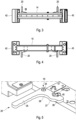
- Figure 3 shows the inventive apparatus in a top view and Figure 4 illustrates the inventive apparatus in a bottom view.
- the locking levers 20 are L-shaped. A user may grasp the longer leg of the levers 20 in order to rotate the lever such that a recess which is positioned at the shorter leg of the levers 20 engages the locking pin 21. This is further explained in relation with Figure 5 .
- FIG. 5 is a three-dimensional illustration of higher detail showing a locking lever 20 which is attached to the carrier 15.
- the L-shaped lever 20 comprises a long leg 25 and a short leg 26.
- the pivot shaft 24 which attaches the lever 20 to the carrier 15 is positioned in a transition region 44 between the legs 25, 26.
- the transition region 44 furthermore comprises a strengthening which is configured as a rounded section 28 arranged inwards of the pivot shaft 24 (the side of the "L" at which the legs 25, 26 face each other is considered as the inner side of the "L").
- the short leg 26 comprises a recess 29 which is configured for engagement with the locking pin 21 (not shown in Figure 5 ).
- the recess 29 is arranged at the outer side of the short leg 26.
- a further strengthening which is configured as a rounded section 27.
- the recess 29 comprises two cavities 45 which are configured to receive a resilient member (not shown in Figure 5 ).
- the resilient member is deformed by the locking pin 21 while the locking pin 21 moves relative to the locking lever 20 into the arrested position.
- the cavities comprise cut-outs at an inner wall thereof.
- a cut-out 46 is illustrated in Figure 5 by means of a dotted line. The cut-out may be filled with adhesive in order to firmly fix the resilient member into the cavity.
- FIG 6 illustrates a damping unit 16 of the inventive apparatus in a perspective view.
- Figure 7 illustrates the damping unit 16 in a front view.
- the damping unit 16 comprises a body 52 having a receptacle 50 for receiving an end of the carrier 15. Through-holes 51 are provided through the receptacle to allow insertion of fastening elements which are configured to firmly attach the damping unit 16 to the carrier 15.
- the damping unit 16 furthermore comprises a mounting member 17 which is linearly movable with regard to the body 52 and, thus, with regard to the carrier 15.
- the mounting member 17 comprises a circular socket 53 for receiving the trunnion 23 of the housing so that the housing may be suspended on two damping units as illustrated in Figure 1 .
- the mounting member 17 is connected to the body 52 by means of spring elements 18a. Furthermore, a resilient member 18b being configured as a cube made of resilient material is arranged between the mounting member 17 and the receptacle 50.
- the body 52 is configured to linearly a guide the mounting member 17 in a vertical direction. However, a clearance of about 1 mm is provided between the outer surface of the mounting member 17 and the inner surfaces of the body 52 facing the mounting member 17. Accordingly, the mounting member 17 may be slightly moved in directions other than the vertical direction.
- forces acting on the carrier 15 are at least partially attenuated by the spring elements 18a and/or the resilient member 18b.
- FIG 8 illustrates a housing 14 of the inventive apparatus as well as the interior of the housing.
- the housing 14 comprises a first frame module 61, a second frame module 62, and a middle frame module 63. While, in the assembled state of the housing 14, the middle frame module 63 is arranged between the first frame module 61 and the second frame module 62 such that the first and second frame modules 61, 62 sealingly engage the middle frame module 63, in Figure 8 the first frame module 61 is detached from the other frame modules for illustration purposes.
- FIG 8 shows a board 64 comprising electronic components such as control hardware for driving the display, data communication equipment, data storage devices, and sensors.
- the board 64 is attached to the second frame module 62 such that it is enclosed by the housing (in the assembled state of the housing).
- the second frame module 62 comprises attachment elements 65 which protrude towards the middle frame element 63 in the direction of stacking of the frame modules 61, 62, 63.
- the attachment elements 65 are configured as connecting plates having through holes.
- the middle frame module comprises corresponding through-holes formed in its outer circumference, wherein the through-holes of the middle frame module 63 overlap and are aligned with the through-holes of the connecting plates 65.
- Attachment screws 66 which are accessible from the outside of the housing 14 are inserted through the overlapping through holes in order to fix the second frame module 62 to the middle frame module 63.
- the middle frame module 63 likewise comprises attachment elements 65 being configured as connecting plates having through holes.
- the first frame module 61 is configured identical to the second frame module 62.
- the frame modules 61, 62 therefore may be interchangeably used on both sides of the middle frame module 63.
- a sealing element 67 being configured as an endless band made of elastic material (illustrated only schematically in Figure 8 ) is placed between the first frame module 61 and the middle frame module 63 as well as between the second frame module 62 and the middle frame module 63.
- the sealing element 67 is placed on a sealing surface of the middle frame module 63 which is arranged along an outer contour of the middle frame module 63 which faces in the direction of stacking.
- the first and second frame modules 61, 62 comprise corresponding sealing surfaces arranged along their respective outer contour.
- the sealing element 67 is compressed between the ceiling surfaces of the middle frame module 63 and the respective first or second frame module 61, 62.
- the attachment elements of the first, second, and middle frame modules 61, 62, 63 are configured such that an overlap of the attachment elements comes along with a sufficient compression of the sealing element 67 so that a sufficient ceiling action is ensured.
Landscapes
- Engineering & Computer Science (AREA)
- Mechanical Engineering (AREA)
- Business, Economics & Management (AREA)
- Accounting & Taxation (AREA)
- Marketing (AREA)
- Physics & Mathematics (AREA)
- General Physics & Mathematics (AREA)
- Theoretical Computer Science (AREA)
- Fittings On The Vehicle Exterior For Carrying Loads, And Devices For Holding Or Mounting Articles (AREA)
Description
- The present invention relates to an apparatus for mounting on a vehicle roof and for displaying information.
- It is known to mount such apparatuses on the roof of a car in order to show information, such as advertisement, to the surroundings of the vehicle. For instance,
US 2018/0272959 A1 discloses a cross bar for mounting a vehicle topper to a roof of a vehicle according to the preamble of claim 1, which has a center section with a substantially rectangular cross section, wherein tapered sections are attached at a proximal end to each side of the center section and wherein outer plates are located on the distal end of each respective tapered section. - A problem arising in the prior art is that the operating conditions on the top of the vehicle are challenging. In particular, mechanical stress caused by speed changes or concussions which are transmitted from the moving vehicle to the housing may impair the integrity of the housing and of the components arranged therein.
- In view of the above, it is an object of the present invention to provide an apparatus for mounting on a vehicle roof which allows a more reliable operation. The object is solved by the features of the independent claims. Preferable embodiments are described in the dependent claims.
- The inventive apparatus comprises a housing and a mounting fixture configured to support the housing. The housing encloses at least one display. According to the invention, the mounting fixture comprises a carrier being attachable to the roof of the vehicle and a damping unit which connects the carrier to the housing, wherein the damping unit is configured to allow movement of the housing relative to the carrier against a restoring force.
- The carrier may be attached to the roof of the vehicle. The carrier usually has a longitudinal extension which may be oriented along the longitudinal axis of the vehicle. Herein the vehicle roof is considered as defining a horizontal reference plane. The term "vertical" is considered to be an orientation which is perpendicular to this reference plane.
- The carrier is usually firmly attached to the roof of the vehicle so that any movements of the vehicle are directly transmitted to the carrier. This may cause large forces acting on the carrier in case the vehicle performs strong braking operations or moves over uneven surfaces. By means of the inventive damping unit, however, which connects the carrier to the housing, the forces are not fully transmitted from the carrier to the housing. Rather, due to the movability of the housing relative to the carrier against a restoring force, at least a part of the forces is compensated. The inventive features may reliably protect the housing and the components arranged therein against mechanical damage.
- The display may be a flat panel display such as a liquid crystal display (LCD), a light emitting diode (LED) display, or an electronic paper display. A horizontal length of the display may be between 80 cm and 120 cm and a vertical height may be between preferably between 15 cm and 40 cm. The apparatus may comprise a single display. However, in a preferable embodiment the apparatus comprises two displays being arranged such that the viewing sides of the displays are directed into opposite directions. This allows viewing information from two opposite sides of the vehicle.
- The housing preferably encloses the display or displays in order to prevent external influences, such as rain or soil, to inadvertently affect the elements arranged inside the housing. In front of the display(s) the housing may comprise a transparent cover to allow visibility of the display(s) from the outside. The housing may be arranged on the roof of the vehicle such that a viewing plane of the display or displays is arranged essentially parallel to a longitudinal axis of the vehicle and perpendicular to a horizontal plane.
- The housing may comprise a single connection point at which it is connected to the carrier by means of the damping unit in order to be supported with regard to the carrier. However, in a preferred embodiment, the housing comprises two connection points being arranged at opposite sides of the housing. In this case, the apparatus may comprise two damping units, wherein each damping unit is connected to a respective connection point of the housing. In parts of the following description reference is made to only a single connection point and/or to a single damping unit for the sake of simplicity. However, it is to be understood that the present disclosure may also comprise embodiments having two or more connection points and/or corresponding damping units.
- According to the invention, the damping unit comprises a mounting member which holds the housing and a restoring element which is arranged between the mounting member and the carrier. In that case the housing and the mounting member are movable together with regard to the carrier, wherein the movement charges the restoring element. The mounting member may in this case be configured for connection with the connection point of the housing.
- The mounting member is arranged above the carrier. Furthermore, the mounting member may be movable along a direction which encloses an angle with a horizontal plane, wherein the angle is preferably between 70° and 110°, further preferably between 80° and 100°, even further preferably between 85° and 95°. This configuration allows the mounting member (as well as the housing connected thereto) to move essentially vertically towards or away from the carrier. This allows an efficient attenuation of vertical accelerations of the vehicle which may arise, for instance, if the vehicle drives over bumpy roads. The damping unit comprises a guide for linearly guiding the mounting member with regard to the carrier. The guide may have a main direction corresponding to the above-noted direction of movability of the mounting member. The guide further may have a clearance allowing movement of the mounting member (and the housing attached thereto) along directions being perpendicular to the main direction of the guide, the clearance being smaller than 10 mm, preferably smaller than 5 mm, further preferably smaller than 3 mm, even further preferably smaller than 1,5 mm.
- In an embodiment the restoring element comprises a spring element, wherein the spring element preferably connects the mounting member to the carrier. Using a spring element is advantageous in that it has a main axis along which it can be compressed and/or extended to cause a restoring force. This main axis may be oriented along the above-noted direction of movability of the mounting element. In particular, the main axis may be oriented essentially vertical in order to efficiently absorb vertical accelerations of the vehicle. Further, a spring element may also be deflected in a plane perpendicular to the main axis against a restoring force so that forces along other directions may lik 4a be attenuated.
- Alternatively or in addition, the restoring element may comprise a resilient member. The resilient member may be compressed if the mounting member is moved towards the carrier.
- The housing may be configured to be rotatable between a deployed position and a rest position. For instance, the connection point of the housing may comprise a trunnion and the mounting member may comprise a corresponding socket for receiving the trunnion. The housing may be rotatable with respect to the carrier around an axis of the trunnion.
- The apparatus may further comprise a locking lever configured to be moved into a locking position to arrest the housing in the deployed position. The locking lever may be fixed with regard to the carrier. The locking lever may comprise a recess for engaging around a locking pin of the housing, wherein a resilient locking member is arranged in the recess, the resilient locking member being configured to be deformed by the locking pin upon movement of the locking lever into the locking position, wherein the resilient locking member is preferably configured to engage behind the locking pin in the locking position. If the resilient locking member needs to be deformed to allow passage of the locking pin and engages behind the locking pin, the locking lever is reliably held in the locking position. The recess may comprise a cavity for receiving the resilient locking member. The resilient locking member is further preferably attached to the locking lever by means of an adhesive. Further preferably, an inner wall of the cavity comprises at least one cutout for receiving the adhesive. The group of features noted in this paragraph may constitute an invention on its own, even without provision of a damping unit which connects the carrier to the housing, wherein the damping unit is configured to allow movement of the housing relative to the carrier against a restoring force.
- In an embodiment, the locking lever has a first leg and a second leg, the legs enclosing an angle between each other which is 70° to 110°, preferably 80° to 100°, further preferably 85° to 95°. The locking lever may, in particular, be L-shaped. The first leg may be longer than the second leg and may be configured to be gripped by a user for moving the lever between the locking and unlocking positions. The recess may be arranged at the second leg. The locking lever is preferably connected to the carrier at an attachment point located in an area of a transition between the first and second legs of the locking lever. Furthermore, the area of transition may preferably comprise a strengthened portion which is arranged on the inside of the attachment point between the locking lever and the carrier. The locking lever may also comprise a strengthened portion which is positioned at the second leg opposite the recess. The strengthened portions may, in particular, be configured as rounded portions. The group of features noted in this paragraph may constitute an invention on its own, even without provision of a damping unit which connects the carrier to the housing, wherein the damping unit is configured to allow movement of the housing relative to the carrier against a restoring force.
- In a preferable embodiment the apparatus comprises a first display having a first viewing side and a second display having a second viewing side, wherein the housing encloses the first display and the second display and wherein the housing comprises
- a first frame module enclosing the first viewing side and a circumference of the first display,
- a second frame module enclosing the second viewing side and a circumference of the second display, and
- a middle frame module being arranged between the first and second frame modules and configured to sealingly engage the first and second frame modules so that the first display and the second display are enclosed by the housing.
- This construction is particularly beneficial, as it allows to separately manufacture the first and second frame modules to which a respective display and further components such as electronics and sensors may be attached and to subsequently assemble the housing in an efficient manner. The above-described idea to assemble the housing by means of three separate frame modules may constitute an invention on its own, even without provision of a damping unit which connects the carrier to the housing, wherein the damping unit is configured to allow movement of the housing relative to the carrier against a restoring force.
- In a preferable embodiment, the first display is attached to the first frame module and the second display is attached to the second frame module. Further electronic components such as control hardware for driving the display, data communication equipment, data storage devices, or sensors may likewise be mounted in the first and/or second frame module prior to attaching the modules to the middle frame module.
- The first and second frame modules may each comprise attachment elements which overlap with corresponding attachment elements of the middle frame module. The attachment elements are brought into overlap during assembly by moving the first/second frame module towards the middle frame module. Preferably, the attachment elements are accessible from the outside of the housing and allow fixing the first and/or second frame modules to the middle frame module. The middle frame module may, in particular, have a first group of attachment elements overlapping with the attachment elements of the first frame module and a second group of attachment elements overlapping with the attachment elements of the second frame module.
- The first and second frame modules and the middle frame module have an outer contour viewed in a direction of stacking of the first / second frame module. A sealing element may be placed between at least one of the first or second frame modules and the middle frame module. The sealing element may have the shape of an endless band and may be configured to be placed along an outer contour of the first/second frame modules. At least one of the first, second or middle frame modules may comprise an outer ridge around its outer contour to prevent the sealing element from moving to the outside of the housing during assembly.
- During assembly, the attachment elements may be brought into overlap in order to fix the modules together. At the same time the sealing element is preferably compressed to ensure that the inside of the housing is sealed from the outside. The attachment elements may be positioned such that an overlap of the attachment elements comes along with a compression of the sealing element. This allows to ensure a sufficient sealing action.
- The attachment elements may, for instance, be configured as through-holes which, in the assembled state of the housing, overlap with corresponding through-holes of the respective adjacent frame module. Fastening elements may be inserted through the overlapping through-holes in order to secure the modules together.
- In an embodiment, the first frame module is configured such that it can be interchangeably used as a second frame module. In particular, the attachment elements of middle frame module may be provided in a rotationally symmetric manner with regard to a rotation about a middle axis of the middle frame module. The middle axis may be perpendicular to the direction of stacking of the first, second, and middle frame modules. The above-noted features allow a considerable reduction in production costs, as one and the same frame module may be used both as the first and second frame module and, accordingly, the number of variants to be produced is reduced.
- The invention is furthermore directed to a kit comprising an inventive apparatus for mounting on a vehicle roof and at least one attachment bracket for fixing the carrier to a roof rack of the vehicle.
- The attachment bracket is configured to engage around the carrier and preferably comprises fastening elements for fixing the bracket to a crossbeam of the roof rack. The cross beam may be arranged along a transverse direction of the vehicle. The above-noted kit may constitute an invention of its own, even without provision of a damping unit which connects the carrier to the housing, wherein the damping unit is configured to allow movement of the housing relative to the carrier against a restoring force.
- The different aspects of the invention are particularly beneficial in that they allow a safe operation of delicate electronic components such as a control unit for driving the display, data communication equipment, data storage devices, and environmental sensors to be introduced into the housing and to be safely operated on the roof of the vehicle. By means of the inventive aspects such components are, on the one hand, safely protected from mechanical stress and, on the other hand, safely sealed from outer influences such as rain or soil. In particular, the inventive aspects allow the introduction and operation of sensors for the collection of traffic data and/or environmental data (such as temperature data and/or humidity data) and/or geographic position data and/or demographic data (such as the age and/or gender of pedestrians in the vicinity of the inventive apparatus) in an economically efficient manner. The collected data may be used for controlling the content which is displayed on the inventive apparatus.
- The invention is further described in the following by means of preferable embodiments which are illustrated by the attached drawings which show:
- Fig. 1:
- a side view of an apparatus for mounting on a vehicle roof according to the invention;
- Fig. 2:
- a side view of the apparatus of
Figure 1 at a higher detail; - Fig. 2a:
- a perspective view of an attachment bracket for fixing the apparatus to a roof rack of the vehicle in a perspective view,
- Fig. 2b:
- the attachment bracket of
Figure 2a in a front view, - Fig. 3:
- a top view of the apparatus of
Figure 1 ; - Fig. 4:
- a bottom view of the apparatus of
Figure 1 ; - Fig. 5:
- a three-dimensional illustration of a locking lever of the inventive apparatus of
Figure 1 at a higher detail; - Fig. 6:
- the damping unit of the inventive apparatus in a perspective view;
- Fig. 7:
- the damping unit of the inventive apparatus in a front view;
- Fig. 8:
- a housing of the inventive apparatus in a perspective view.
-
Figure 1 illustrates a side view of an inventive apparatus which is mounted on aroof 41 of avehicle 40. The apparatus comprises a mountingfixture 13 and ahousing 14. Adisplay 31 is arranged inside thehousing 14. A further display (which is not visible inFigure 1 ) is positioned on the other side of thehousing 14 such that information can be displayed on both sides of the vehicle. Thehousing 14 as well as the viewing areas of the displays is arranged essentially parallel to a longitudinal axis of the vehicle and essentially perpendicular to a horizontal plane which is defined by theroof 41. - The mounting
fixture 13 comprises acarrier 15 which is attached to theroof 41. A longitudinal axis of thecarrier 15 is oriented parallel to the longitudinal axis of thevehicle 40. At each of its longitudinal ends thecarrier 16 comprises a dampingunit 16. Thehousing 14 is connected to the dampingunits 16 so that it is suspended above thecarrier 15. For this purpose, thehousing 14 comprisestrunnions 23 located at opposite sides of thehousing 14 and extending in a longitudinal direction. Thetrunnions 23 are inserted into corresponding sockets 53 (not visible inFigure 1 but shown inFigures 6 and 7 ) of the dampingunits 16. The dampingunits 16 are configured such that the housing is movable relative to thecarrier 15 against a restoring force. This is further explained with regard toFigures 6-7 . - The
housing 14 may be rotated about a longitudinal axis defined by the axis of thetrunnions 23 from a deployed position (which is shown inFigure 1 ) into a rest position (not shown). In order to arrest thehousing 14 in the deployed position, the apparatus comprises locking levers which are omitted for the sake of clarity inFigure 1 and which are, however, illustrated inFigure 2 . - Furthermore, the apparatus comprises a front taxi sign and a back taxi sign which is attached to the longitudinal ends of the mounting
fixture 13. The taxi signs are likewise omitted inFigure 1 for the sake of clarity, but are illustrated inFigure 2 . -
Figure 2 shows an enlarged illustration of the apparatus ofFigure 1 . The apparatus comprises afirst taxi sign 42 directing to the front of the vehicle and asecond taxi sign 43 directing to the back of the vehicle. The taxi signs 42, 43 cover the dampingunits 16 which are therefore not visible inFigure 2 . - Furthermore,
Figure 2 shows two lockinglevers 20 each being mounted to thecarrier 15 by means of apivot shaft 24. Each lockinglever 20 is rotatable about a vertical axis defined by thepivot shaft 24. Thehousing 14 furthermore comprises two lockingpins 21 which protrude downwards. The locking levers 20 can be brought into engagement with therespective locking pin 21 in order to arrest the housing in the deployed position. -
Figure 2a is a perspective view of anattachment bracket 70 for fixing the inventive apparatus to a roof rack of thevehicle 40.Figure 2b shows a front view of theattachment bracket 70. Theattachment bracket 70 comprises aclamp element 71 which is angled so that it may firmly engage around the outer circumference of thecarrier 15 along a transversal direction of thecarrier 15. At each of its longitudinal ends thebracket 70 comprises connectingportions 71 having a through hole through which a fastening element is inserted. By means of the fastening element the bracket may be fixed to acrossbeam 74 of the roof rack of the vehicle. Thebracket 70 is configured to firmly clamp thecarrier 15 against the cross beam. -
Figure 3 shows the inventive apparatus in a top view andFigure 4 illustrates the inventive apparatus in a bottom view. - From
Figures 3 and 4 it can be seen that the locking levers 20 are L-shaped. A user may grasp the longer leg of thelevers 20 in order to rotate the lever such that a recess which is positioned at the shorter leg of thelevers 20 engages the lockingpin 21. This is further explained in relation withFigure 5 . -
Figure 5 is a three-dimensional illustration of higher detail showing a lockinglever 20 which is attached to thecarrier 15. The L-shapedlever 20 comprises along leg 25 and ashort leg 26. Thepivot shaft 24 which attaches thelever 20 to thecarrier 15 is positioned in atransition region 44 between thelegs transition region 44 furthermore comprises a strengthening which is configured as arounded section 28 arranged inwards of the pivot shaft 24 (the side of the "L" at which thelegs - Furthermore, the
short leg 26 comprises arecess 29 which is configured for engagement with the locking pin 21 (not shown inFigure 5 ). Therecess 29 is arranged at the outer side of theshort leg 26. At the inner side of theshort leg 26 opposite therecess 29 there is provided a further strengthening which is configured as arounded section 27. By means of therounded sections - The
recess 29 comprises twocavities 45 which are configured to receive a resilient member (not shown inFigure 5 ). The resilient member is deformed by the lockingpin 21 while the lockingpin 21 moves relative to the lockinglever 20 into the arrested position. The cavities comprise cut-outs at an inner wall thereof. A cut-out 46 is illustrated inFigure 5 by means of a dotted line. The cut-out may be filled with adhesive in order to firmly fix the resilient member into the cavity. -
Figure 6 illustrates a dampingunit 16 of the inventive apparatus in a perspective view.Figure 7 illustrates the dampingunit 16 in a front view. The dampingunit 16 comprises abody 52 having areceptacle 50 for receiving an end of thecarrier 15. Through-holes 51 are provided through the receptacle to allow insertion of fastening elements which are configured to firmly attach the dampingunit 16 to thecarrier 15. The dampingunit 16 furthermore comprises a mountingmember 17 which is linearly movable with regard to thebody 52 and, thus, with regard to thecarrier 15. The mountingmember 17 comprises acircular socket 53 for receiving thetrunnion 23 of the housing so that the housing may be suspended on two damping units as illustrated inFigure 1 . - The mounting
member 17 is connected to thebody 52 by means ofspring elements 18a. Furthermore, aresilient member 18b being configured as a cube made of resilient material is arranged between the mountingmember 17 and thereceptacle 50. Thebody 52 is configured to linearly a guide the mountingmember 17 in a vertical direction. However, a clearance of about 1 mm is provided between the outer surface of the mountingmember 17 and the inner surfaces of thebody 52 facing the mountingmember 17. Accordingly, the mountingmember 17 may be slightly moved in directions other than the vertical direction. During operation of the vehicle, forces acting on thecarrier 15 are at least partially attenuated by thespring elements 18a and/or theresilient member 18b. -
Figure 8 illustrates ahousing 14 of the inventive apparatus as well as the interior of the housing. Thehousing 14 comprises afirst frame module 61, asecond frame module 62, and amiddle frame module 63. While, in the assembled state of thehousing 14, themiddle frame module 63 is arranged between thefirst frame module 61 and thesecond frame module 62 such that the first andsecond frame modules middle frame module 63, inFigure 8 thefirst frame module 61 is detached from the other frame modules for illustration purposes. -
Figure 8 shows aboard 64 comprising electronic components such as control hardware for driving the display, data communication equipment, data storage devices, and sensors. Theboard 64 is attached to thesecond frame module 62 such that it is enclosed by the housing (in the assembled state of the housing). On the lower side of the board 64 (not visible inFigure 8 ) a display is arranged. Furthermore, thesecond frame module 62 comprisesattachment elements 65 which protrude towards themiddle frame element 63 in the direction of stacking of theframe modules attachment elements 65 are configured as connecting plates having through holes. The middle frame module comprises corresponding through-holes formed in its outer circumference, wherein the through-holes of themiddle frame module 63 overlap and are aligned with the through-holes of the connectingplates 65. Attachment screws 66 which are accessible from the outside of thehousing 14 are inserted through the overlapping through holes in order to fix thesecond frame module 62 to themiddle frame module 63. - It is noted that only every second through-hole provided in the
middle frame module 63 is used for connection to thesecond frame module 62. Every other of the through holes of themiddle frame module 63 can be used for connection with thefirst frame module 61. For this purpose, thefirst frame module 61 likewise comprisesattachment elements 65 being configured as connecting plates having through holes. - The
first frame module 61 is configured identical to thesecond frame module 62. Theframe modules middle frame module 63. - Prior to assembly of the
housing 14, a sealingelement 67 being configured as an endless band made of elastic material (illustrated only schematically inFigure 8 ) is placed between thefirst frame module 61 and themiddle frame module 63 as well as between thesecond frame module 62 and themiddle frame module 63. InFigure 8 , the sealingelement 67 is placed on a sealing surface of themiddle frame module 63 which is arranged along an outer contour of themiddle frame module 63 which faces in the direction of stacking. The first andsecond frame modules element 67 is compressed between the ceiling surfaces of themiddle frame module 63 and the respective first orsecond frame module middle frame modules element 67 so that a sufficient ceiling action is ensured.
Claims (14)
- Apparatus for mounting on a vehicle roof (41), comprising a housing (14) which encloses at least one display (31, 34), and a mounting fixture (13) configured to support the housing (14), wherein the mounting fixture (13) comprises a carrier (15) being attachable to the roof (41) and a damping unit (16) which connects the carrier (15) to the housing (14), wherein the damping unit (16) is configured to allow movement of the housing (14) relative to the carrier (15) against a restoring force, characterized in that the damping unit (16) comprises a mounting member (17) which holds the housing (14) and a restoring element (18a, 18b) which is arranged between the mounting member (17) and the carrier (15) wherein the mounting member (17) is arranged above the carrier (15), wherein the damping unit comprises a guide (52) for linearly guiding the mounting member with regard to the carrier.
- Apparatus according to claim 1, wherein the mounting member (17) is movable along a direction which encloses an angle with a horizontal plane which is between 70° and 110°, preferably between 80° and 100°, further preferably between 85° and 95°.
- Apparatus according to claim 2, wherein the guide has a clearance allowing movement of the mounting member (17) along at least one direction being perpendicular to the axis of the guide, the clearance being smaller than 10 mm, preferably smaller than 5 mm, further preferably smaller than 3 mm, even further preferably smaller than 1,5 mm.
- Apparatus according to one of claims 1 to 3, wherein the restoring element (18a) comprises a spring element, wherein the spring element preferably connects the mounting member (17) to the carrier (15).
- Apparatus according to one of claims 1 to 4, wherein the restoring element (18b) comprises a resilient member.
- Apparatus according to one of claims 1 to 5, wherein the housing (14) is configured to be rotatable between a deployed position and a rest position, wherein the apparatus further comprises a locking lever (20) configured to be moved into a locking position to arrest the housing (14) in the deployed position, wherein the locking lever (20) comprises a recess (29) for engaging around a locking pin (21) of the housing (14), wherein a resilient locking member is arranged in the recess (29), the resilient locking member being configured to be deformed upon movement of the locking lever (20) into the locking position, wherein the resilient locking member is preferably configured to engage behind the locking pin (21) in the locking position.
- Apparatus according to claim 6, wherein the recess (29) comprises a cavity (45) for receiving the resilient locking member, wherein the resilient locking member is attached to the locking lever (20 ) by means of an adhesive, wherein an inner wall of the cavity (45) preferably comprises at least one cutout for receiving the adhesive.
- Apparatus according to one of claims 1 to 7, comprising a first display (31) having a first viewing side and a second display (31) having a second viewing side, wherein the housing (14) encloses the first display (31) and the second display (31) and wherein the housing (14) comprises:- a first frame module (61) enclosing the first viewing side and a circumference of the first display (31),- a second frame module (62) enclosing the second viewing side and a circumference of the second display (31), and- a middle frame module (63) being arranged between the first and second frame modules (61, 62) and configured to sealingly engage the first and second frame modules (61, 62) so that the first display (31) and the second display (31) are enclosed by the housing (14).
- Apparatus according to claim 8, wherein the first and second frame modules (61, 62) each comprise attachment elements (65) which overlap with corresponding attachment elements of the middle frame module (63), wherein the overlapping attachment elements are accessible from the outside of the housing (14) to allow fixing the first and/or second frame modules (61, 62) to the middle frame module (63).
- Apparatus according to claim 9, wherein the middle frame module (63) has a first group of attachment elements overlapping with the attachment elements (65) of the first frame module (61) and a second group of attachment elements overlapping with the attachment elements (65) of the second frame module (62).
- Apparatus according to one of claims 9 or 10, wherein the attachment elements (65) comprise through-holes which overlap in the assembled state of the housing (14), wherein fastening elements (66) are inserted through the overlapping through-holes, wherein preferably a sealing element (67) is placed between at least one of the first or second frame modules (61, 62) and the middle frame module (63), wherein the attachment elements are further preferably positioned such that the overlap of the attachment elements comes along with a compression of the sealing element (67).
- Apparatus according to one of claims 8 to 11, wherein the first frame module (61) is configured such that it can be interchangeably used as a second frame module (62).
- Apparatus according to one of claims 1 to 12, further comprising- at least one sensor configured for the collection of traffic data and/or environmental data and/or geographic position data and/or demographic data and- a control unit for controlling the display depending on the data collected by the at least one sensor.
- Kit comprising an apparatus according to one of claims 1 to 13 and at least one attachment bracket (70) for fixing the carrier (15) to a roof rack of the vehicle (40).
Priority Applications (1)
| Application Number | Priority Date | Filing Date | Title |
|---|---|---|---|
| EP21185756.0A EP4119396B1 (en) | 2021-07-15 | 2021-07-15 | Apparatus for mounting on a vehicle roof and for displaying information |
Applications Claiming Priority (1)
| Application Number | Priority Date | Filing Date | Title |
|---|---|---|---|
| EP21185756.0A EP4119396B1 (en) | 2021-07-15 | 2021-07-15 | Apparatus for mounting on a vehicle roof and for displaying information |
Publications (3)
| Publication Number | Publication Date |
|---|---|
| EP4119396A1 EP4119396A1 (en) | 2023-01-18 |
| EP4119396B1 true EP4119396B1 (en) | 2024-05-08 |
| EP4119396C0 EP4119396C0 (en) | 2024-05-08 |
Family
ID=76942856
Family Applications (1)
| Application Number | Title | Priority Date | Filing Date |
|---|---|---|---|
| EP21185756.0A Active EP4119396B1 (en) | 2021-07-15 | 2021-07-15 | Apparatus for mounting on a vehicle roof and for displaying information |
Country Status (1)
| Country | Link |
|---|---|
| EP (1) | EP4119396B1 (en) |
Family Cites Families (5)
| Publication number | Priority date | Publication date | Assignee | Title |
|---|---|---|---|---|
| NL8801722A (en) * | 1988-07-07 | 1990-02-01 | Liets Bv | Advertising-board fixture arrangement - has pivot mechanism, for fixing to motor vehicle roof |
| WO2015191866A1 (en) * | 2014-06-13 | 2015-12-17 | Kis-Benedek Pinero Iidiko' | Portable display device and system |
| CA3057321C (en) * | 2017-03-24 | 2022-11-29 | Manufacturing Resources International, Inc. | Roof mounting apparatus and system for vehicle topper |
| DE102017213283A1 (en) * | 2017-08-01 | 2019-02-07 | TAXi-AD GmbH | Roofing carrier for a vehicle |
| US20200377032A1 (en) * | 2019-05-29 | 2020-12-03 | Deyan Alex | Configurable roof rack for vehicles |
-
2021
- 2021-07-15 EP EP21185756.0A patent/EP4119396B1/en active Active
Also Published As
| Publication number | Publication date |
|---|---|
| EP4119396C0 (en) | 2024-05-08 |
| EP4119396A1 (en) | 2023-01-18 |
Similar Documents
| Publication | Publication Date | Title |
|---|---|---|
| US7417866B1 (en) | Electronic equipment module mounting apparatus and method | |
| JP6201321B2 (en) | Display device | |
| ITMI972245A1 (en) | VISUALIZATION SIGN WITH MEANS TO IMPROVE VISIBILITY | |
| JPH0783260A (en) | Isotropic shock-resistant assembly and assembling method thereof | |
| KR101827761B1 (en) | Lamp assembly for vehicle | |
| KR20160083608A (en) | Foldable display apparatus | |
| JP6950715B2 (en) | Vehicle display device | |
| GB2337538A (en) | Tubular mast | |
| CN103930941A (en) | Display device for transportation vehicle | |
| EP0420650B1 (en) | Meter device | |
| EP4119396B1 (en) | Apparatus for mounting on a vehicle roof and for displaying information | |
| EP0594367B1 (en) | A display device | |
| US20090015998A1 (en) | Advanced lcd packaging for military and severe environments | |
| JP2000194269A (en) | Housing structure | |
| US9377573B2 (en) | Lighting device and display device having the lighting device | |
| JP4712461B2 (en) | Display panel connection cable protection structure and vehicle instrument assembly method | |
| JP6211688B2 (en) | Display panel module, display device, and manufacturing method | |
| KR200459119Y1 (en) | Head-up display apparatus | |
| US7896535B2 (en) | Display module | |
| KR101087235B1 (en) | Organic electroluminescent device kit | |
| US11922795B2 (en) | Support component of a housing of a hazard alert center and a hazard alert center, preferably an intruder alert, fire alarm and/or extinguishing control center | |
| JPH06337317A (en) | Front plate structure of electronic circuit package | |
| KR20090055986A (en) | Display | |
| KR20100121165A (en) | Display device | |
| CN220855353U (en) | Head-up display device |
Legal Events
| Date | Code | Title | Description |
|---|---|---|---|
| PUAI | Public reference made under article 153(3) epc to a published international application that has entered the european phase |
Free format text: ORIGINAL CODE: 0009012 |
|
| STAA | Information on the status of an ep patent application or granted ep patent |
Free format text: STATUS: THE APPLICATION HAS BEEN PUBLISHED |
|
| AK | Designated contracting states |
Kind code of ref document: A1 Designated state(s): AL AT BE BG CH CY CZ DE DK EE ES FI FR GB GR HR HU IE IS IT LI LT LU LV MC MK MT NL NO PL PT RO RS SE SI SK SM TR |
|
| P01 | Opt-out of the competence of the unified patent court (upc) registered |
Effective date: 20230515 |
|
| STAA | Information on the status of an ep patent application or granted ep patent |
Free format text: STATUS: REQUEST FOR EXAMINATION WAS MADE |
|
| 17P | Request for examination filed |
Effective date: 20230703 |
|
| RBV | Designated contracting states (corrected) |
Designated state(s): AL AT BE BG CH CY CZ DE DK EE ES FI FR GB GR HR HU IE IS IT LI LT LU LV MC MK MT NL NO PL PT RO RS SE SI SK SM TR |
|
| GRAP | Despatch of communication of intention to grant a patent |
Free format text: ORIGINAL CODE: EPIDOSNIGR1 |
|
| STAA | Information on the status of an ep patent application or granted ep patent |
Free format text: STATUS: GRANT OF PATENT IS INTENDED |
|
| INTG | Intention to grant announced |
Effective date: 20240123 |
|
| GRAS | Grant fee paid |
Free format text: ORIGINAL CODE: EPIDOSNIGR3 |
|
| GRAA | (expected) grant |
Free format text: ORIGINAL CODE: 0009210 |
|
| STAA | Information on the status of an ep patent application or granted ep patent |
Free format text: STATUS: THE PATENT HAS BEEN GRANTED |
|
| AK | Designated contracting states |
Kind code of ref document: B1 Designated state(s): AL AT BE BG CH CY CZ DE DK EE ES FI FR GB GR HR HU IE IS IT LI LT LU LV MC MK MT NL NO PL PT RO RS SE SI SK SM TR |
|
| REG | Reference to a national code |
Ref country code: GB Ref legal event code: FG4D |
|
| REG | Reference to a national code |
Ref country code: CH Ref legal event code: EP |
|
| RAP4 | Party data changed (patent owner data changed or rights of a patent transferred) |
Owner name: UZE! MOBILITY GMBH |
|
| REG | Reference to a national code |
Ref country code: DE Ref legal event code: R096 Ref document number: 602021012971 Country of ref document: DE |
|
| REG | Reference to a national code |
Ref country code: IE Ref legal event code: FG4D |
|
| U01 | Request for unitary effect filed |
Effective date: 20240528 |
|
| P04 | Withdrawal of opt-out of the competence of the unified patent court (upc) registered |
Free format text: CASE NUMBER: APP_33185/2024 Effective date: 20240603 |
|
| U07 | Unitary effect registered |
Designated state(s): AT BE BG DE DK EE FI FR IT LT LU LV MT NL PT SE SI Effective date: 20240606 |
|
| U20 | Renewal fee for the european patent with unitary effect paid |
Year of fee payment: 4 Effective date: 20240724 |
|
| PG25 | Lapsed in a contracting state [announced via postgrant information from national office to epo] |
Ref country code: IS Free format text: LAPSE BECAUSE OF FAILURE TO SUBMIT A TRANSLATION OF THE DESCRIPTION OR TO PAY THE FEE WITHIN THE PRESCRIBED TIME-LIMIT Effective date: 20240908 |
|
| PG25 | Lapsed in a contracting state [announced via postgrant information from national office to epo] |
Ref country code: HR Free format text: LAPSE BECAUSE OF FAILURE TO SUBMIT A TRANSLATION OF THE DESCRIPTION OR TO PAY THE FEE WITHIN THE PRESCRIBED TIME-LIMIT Effective date: 20240508 |
|
| PG25 | Lapsed in a contracting state [announced via postgrant information from national office to epo] |
Ref country code: GR Free format text: LAPSE BECAUSE OF FAILURE TO SUBMIT A TRANSLATION OF THE DESCRIPTION OR TO PAY THE FEE WITHIN THE PRESCRIBED TIME-LIMIT Effective date: 20240809 |
|
| PG25 | Lapsed in a contracting state [announced via postgrant information from national office to epo] |
Ref country code: ES Free format text: LAPSE BECAUSE OF FAILURE TO SUBMIT A TRANSLATION OF THE DESCRIPTION OR TO PAY THE FEE WITHIN THE PRESCRIBED TIME-LIMIT Effective date: 20240508 |
|
| PG25 | Lapsed in a contracting state [announced via postgrant information from national office to epo] |
Ref country code: PL Free format text: LAPSE BECAUSE OF FAILURE TO SUBMIT A TRANSLATION OF THE DESCRIPTION OR TO PAY THE FEE WITHIN THE PRESCRIBED TIME-LIMIT Effective date: 20240508 |
|
| PG25 | Lapsed in a contracting state [announced via postgrant information from national office to epo] |
Ref country code: PL Free format text: LAPSE BECAUSE OF FAILURE TO SUBMIT A TRANSLATION OF THE DESCRIPTION OR TO PAY THE FEE WITHIN THE PRESCRIBED TIME-LIMIT Effective date: 20240508 Ref country code: NO Free format text: LAPSE BECAUSE OF FAILURE TO SUBMIT A TRANSLATION OF THE DESCRIPTION OR TO PAY THE FEE WITHIN THE PRESCRIBED TIME-LIMIT Effective date: 20240808 Ref country code: IS Free format text: LAPSE BECAUSE OF FAILURE TO SUBMIT A TRANSLATION OF THE DESCRIPTION OR TO PAY THE FEE WITHIN THE PRESCRIBED TIME-LIMIT Effective date: 20240908 Ref country code: HR Free format text: LAPSE BECAUSE OF FAILURE TO SUBMIT A TRANSLATION OF THE DESCRIPTION OR TO PAY THE FEE WITHIN THE PRESCRIBED TIME-LIMIT Effective date: 20240508 Ref country code: GR Free format text: LAPSE BECAUSE OF FAILURE TO SUBMIT A TRANSLATION OF THE DESCRIPTION OR TO PAY THE FEE WITHIN THE PRESCRIBED TIME-LIMIT Effective date: 20240809 Ref country code: ES Free format text: LAPSE BECAUSE OF FAILURE TO SUBMIT A TRANSLATION OF THE DESCRIPTION OR TO PAY THE FEE WITHIN THE PRESCRIBED TIME-LIMIT Effective date: 20240508 Ref country code: RS Free format text: LAPSE BECAUSE OF FAILURE TO SUBMIT A TRANSLATION OF THE DESCRIPTION OR TO PAY THE FEE WITHIN THE PRESCRIBED TIME-LIMIT Effective date: 20240808 |
|
| P05 | Withdrawal of opt-out of the competence of the unified patent court (upc) changed |
Free format text: CASE NUMBER: APP_33185/2024 Effective date: 20240606 |
|
| PG25 | Lapsed in a contracting state [announced via postgrant information from national office to epo] |
Ref country code: CZ Free format text: LAPSE BECAUSE OF FAILURE TO SUBMIT A TRANSLATION OF THE DESCRIPTION OR TO PAY THE FEE WITHIN THE PRESCRIBED TIME-LIMIT Effective date: 20240508 |
|
| PG25 | Lapsed in a contracting state [announced via postgrant information from national office to epo] |
Ref country code: SK Free format text: LAPSE BECAUSE OF FAILURE TO SUBMIT A TRANSLATION OF THE DESCRIPTION OR TO PAY THE FEE WITHIN THE PRESCRIBED TIME-LIMIT Effective date: 20240508 Ref country code: RO Free format text: LAPSE BECAUSE OF FAILURE TO SUBMIT A TRANSLATION OF THE DESCRIPTION OR TO PAY THE FEE WITHIN THE PRESCRIBED TIME-LIMIT Effective date: 20240508 |
|
| PG25 | Lapsed in a contracting state [announced via postgrant information from national office to epo] |
Ref country code: SM Free format text: LAPSE BECAUSE OF FAILURE TO SUBMIT A TRANSLATION OF THE DESCRIPTION OR TO PAY THE FEE WITHIN THE PRESCRIBED TIME-LIMIT Effective date: 20240508 |
|
| PG25 | Lapsed in a contracting state [announced via postgrant information from national office to epo] |
Ref country code: SM Free format text: LAPSE BECAUSE OF FAILURE TO SUBMIT A TRANSLATION OF THE DESCRIPTION OR TO PAY THE FEE WITHIN THE PRESCRIBED TIME-LIMIT Effective date: 20240508 Ref country code: SK Free format text: LAPSE BECAUSE OF FAILURE TO SUBMIT A TRANSLATION OF THE DESCRIPTION OR TO PAY THE FEE WITHIN THE PRESCRIBED TIME-LIMIT Effective date: 20240508 Ref country code: RO Free format text: LAPSE BECAUSE OF FAILURE TO SUBMIT A TRANSLATION OF THE DESCRIPTION OR TO PAY THE FEE WITHIN THE PRESCRIBED TIME-LIMIT Effective date: 20240508 Ref country code: CZ Free format text: LAPSE BECAUSE OF FAILURE TO SUBMIT A TRANSLATION OF THE DESCRIPTION OR TO PAY THE FEE WITHIN THE PRESCRIBED TIME-LIMIT Effective date: 20240508 |
|
| PG25 | Lapsed in a contracting state [announced via postgrant information from national office to epo] |
Ref country code: MC Free format text: LAPSE BECAUSE OF FAILURE TO SUBMIT A TRANSLATION OF THE DESCRIPTION OR TO PAY THE FEE WITHIN THE PRESCRIBED TIME-LIMIT Effective date: 20240508 |
|
| REG | Reference to a national code |
Ref country code: DE Ref legal event code: R097 Ref document number: 602021012971 Country of ref document: DE |
|
| REG | Reference to a national code |
Ref country code: CH Ref legal event code: PL |
|
| PLBE | No opposition filed within time limit |
Free format text: ORIGINAL CODE: 0009261 |
|
| STAA | Information on the status of an ep patent application or granted ep patent |
Free format text: STATUS: NO OPPOSITION FILED WITHIN TIME LIMIT |
|
| 26N | No opposition filed |
Effective date: 20250211 |
|
| PG25 | Lapsed in a contracting state [announced via postgrant information from national office to epo] |
Ref country code: CH Free format text: LAPSE BECAUSE OF NON-PAYMENT OF DUE FEES Effective date: 20240731 |
|
| PG25 | Lapsed in a contracting state [announced via postgrant information from national office to epo] |
Ref country code: IE Free format text: LAPSE BECAUSE OF NON-PAYMENT OF DUE FEES Effective date: 20240715 |
|
| U20 | Renewal fee for the european patent with unitary effect paid |
Year of fee payment: 5 Effective date: 20250722 |
|
| PG25 | Lapsed in a contracting state [announced via postgrant information from national office to epo] |
Ref country code: CY Free format text: LAPSE BECAUSE OF FAILURE TO SUBMIT A TRANSLATION OF THE DESCRIPTION OR TO PAY THE FEE WITHIN THE PRESCRIBED TIME-LIMIT; INVALID AB INITIO Effective date: 20210715 |
|
| PG25 | Lapsed in a contracting state [announced via postgrant information from national office to epo] |
Ref country code: HU Free format text: LAPSE BECAUSE OF FAILURE TO SUBMIT A TRANSLATION OF THE DESCRIPTION OR TO PAY THE FEE WITHIN THE PRESCRIBED TIME-LIMIT; INVALID AB INITIO Effective date: 20210715 |
|
| GBPC | Gb: european patent ceased through non-payment of renewal fee |
Effective date: 20250715 |
|
| PG25 | Lapsed in a contracting state [announced via postgrant information from national office to epo] |
Ref country code: GB Free format text: LAPSE BECAUSE OF NON-PAYMENT OF DUE FEES Effective date: 20250715 |