EP4119263A1 - Additive modeling device and method for controlling additive modeling device - Google Patents
Additive modeling device and method for controlling additive modeling device Download PDFInfo
- Publication number
- EP4119263A1 EP4119263A1 EP20924892.1A EP20924892A EP4119263A1 EP 4119263 A1 EP4119263 A1 EP 4119263A1 EP 20924892 A EP20924892 A EP 20924892A EP 4119263 A1 EP4119263 A1 EP 4119263A1
- Authority
- EP
- European Patent Office
- Prior art keywords
- modeling
- beam irradiation
- powder
- additive
- control device
- Prior art date
- Legal status (The legal status is an assumption and is not a legal conclusion. Google has not performed a legal analysis and makes no representation as to the accuracy of the status listed.)
- Pending
Links
Images

Classifications
-
- B—PERFORMING OPERATIONS; TRANSPORTING
- B22—CASTING; POWDER METALLURGY
- B22F—WORKING METALLIC POWDER; MANUFACTURE OF ARTICLES FROM METALLIC POWDER; MAKING METALLIC POWDER; APPARATUS OR DEVICES SPECIALLY ADAPTED FOR METALLIC POWDER
- B22F10/00—Additive manufacturing of workpieces or articles from metallic powder
- B22F10/20—Direct sintering or melting
- B22F10/28—Powder bed fusion, e.g. selective laser melting [SLM] or electron beam melting [EBM]
-
- B—PERFORMING OPERATIONS; TRANSPORTING
- B22—CASTING; POWDER METALLURGY
- B22F—WORKING METALLIC POWDER; MANUFACTURE OF ARTICLES FROM METALLIC POWDER; MAKING METALLIC POWDER; APPARATUS OR DEVICES SPECIALLY ADAPTED FOR METALLIC POWDER
- B22F10/00—Additive manufacturing of workpieces or articles from metallic powder
- B22F10/30—Process control
- B22F10/36—Process control of energy beam parameters
-
- B—PERFORMING OPERATIONS; TRANSPORTING
- B22—CASTING; POWDER METALLURGY
- B22F—WORKING METALLIC POWDER; MANUFACTURE OF ARTICLES FROM METALLIC POWDER; MAKING METALLIC POWDER; APPARATUS OR DEVICES SPECIALLY ADAPTED FOR METALLIC POWDER
- B22F10/00—Additive manufacturing of workpieces or articles from metallic powder
- B22F10/30—Process control
- B22F10/36—Process control of energy beam parameters
- B22F10/366—Scanning parameters, e.g. hatch distance or scanning strategy
-
- B—PERFORMING OPERATIONS; TRANSPORTING
- B22—CASTING; POWDER METALLURGY
- B22F—WORKING METALLIC POWDER; MANUFACTURE OF ARTICLES FROM METALLIC POWDER; MAKING METALLIC POWDER; APPARATUS OR DEVICES SPECIALLY ADAPTED FOR METALLIC POWDER
- B22F10/00—Additive manufacturing of workpieces or articles from metallic powder
- B22F10/30—Process control
- B22F10/36—Process control of energy beam parameters
- B22F10/368—Temperature or temperature gradient, e.g. temperature of the melt pool
-
- B—PERFORMING OPERATIONS; TRANSPORTING
- B22—CASTING; POWDER METALLURGY
- B22F—WORKING METALLIC POWDER; MANUFACTURE OF ARTICLES FROM METALLIC POWDER; MAKING METALLIC POWDER; APPARATUS OR DEVICES SPECIALLY ADAPTED FOR METALLIC POWDER
- B22F12/00—Apparatus or devices specially adapted for additive manufacturing; Auxiliary means for additive manufacturing; Combinations of additive manufacturing apparatus or devices with other processing apparatus or devices
- B22F12/40—Radiation means
- B22F12/44—Radiation means characterised by the configuration of the radiation means
- B22F12/45—Two or more
-
- B—PERFORMING OPERATIONS; TRANSPORTING
- B22—CASTING; POWDER METALLURGY
- B22F—WORKING METALLIC POWDER; MANUFACTURE OF ARTICLES FROM METALLIC POWDER; MAKING METALLIC POWDER; APPARATUS OR DEVICES SPECIALLY ADAPTED FOR METALLIC POWDER
- B22F12/00—Apparatus or devices specially adapted for additive manufacturing; Auxiliary means for additive manufacturing; Combinations of additive manufacturing apparatus or devices with other processing apparatus or devices
- B22F12/90—Means for process control, e.g. cameras or sensors
-
- B—PERFORMING OPERATIONS; TRANSPORTING
- B33—ADDITIVE MANUFACTURING TECHNOLOGY
- B33Y—ADDITIVE MANUFACTURING, i.e. MANUFACTURING OF THREE-DIMENSIONAL [3D] OBJECTS BY ADDITIVE DEPOSITION, ADDITIVE AGGLOMERATION OR ADDITIVE LAYERING, e.g. BY 3D PRINTING, STEREOLITHOGRAPHY OR SELECTIVE LASER SINTERING
- B33Y30/00—Apparatus for additive manufacturing; Details thereof or accessories therefor
-
- B—PERFORMING OPERATIONS; TRANSPORTING
- B33—ADDITIVE MANUFACTURING TECHNOLOGY
- B33Y—ADDITIVE MANUFACTURING, i.e. MANUFACTURING OF THREE-DIMENSIONAL [3D] OBJECTS BY ADDITIVE DEPOSITION, ADDITIVE AGGLOMERATION OR ADDITIVE LAYERING, e.g. BY 3D PRINTING, STEREOLITHOGRAPHY OR SELECTIVE LASER SINTERING
- B33Y50/00—Data acquisition or data processing for additive manufacturing
- B33Y50/02—Data acquisition or data processing for additive manufacturing for controlling or regulating additive manufacturing processes
-
- B—PERFORMING OPERATIONS; TRANSPORTING
- B22—CASTING; POWDER METALLURGY
- B22F—WORKING METALLIC POWDER; MANUFACTURE OF ARTICLES FROM METALLIC POWDER; MAKING METALLIC POWDER; APPARATUS OR DEVICES SPECIALLY ADAPTED FOR METALLIC POWDER
- B22F2999/00—Aspects linked to processes or compositions used in powder metallurgy
-
- Y—GENERAL TAGGING OF NEW TECHNOLOGICAL DEVELOPMENTS; GENERAL TAGGING OF CROSS-SECTIONAL TECHNOLOGIES SPANNING OVER SEVERAL SECTIONS OF THE IPC; TECHNICAL SUBJECTS COVERED BY FORMER USPC CROSS-REFERENCE ART COLLECTIONS [XRACs] AND DIGESTS
- Y02—TECHNOLOGIES OR APPLICATIONS FOR MITIGATION OR ADAPTATION AGAINST CLIMATE CHANGE
- Y02P—CLIMATE CHANGE MITIGATION TECHNOLOGIES IN THE PRODUCTION OR PROCESSING OF GOODS
- Y02P10/00—Technologies related to metal processing
- Y02P10/25—Process efficiency
Definitions
- the present invention relates to an additive modeling apparatus and a method of controlling an additive modeling apparatus.
- Three-dimensional additive modeling techniques enable production of a product having a complicated shape, which has been impossible with the conventional processing technique such as cutting, and is expected to be applied in various fields.
- various examinations have also been performed on an additive modeling method using powder.
- a metal deposition method and a powder bed fusion method are known.
- an additive modeled object is obtained by repeating a step of forming a modeled layer by supplying a heated melt of metal powder to a predetermined position and then solidifying the heated melt.
- a thin powder layer is formed in a manner that metal powder is thinly spread on a base plate with a recoater or the like in accordance with predetermined modeling conditions (a beam irradiation condition, a thickness of a powder layer, and the like), based on slice data of a modeled object. Then, the powder layer is selectively melted by irradiating powder at a portion corresponding to the modeled object portion with a beam (for example, a laser beam or an electron beam). Then, the melting is stopped and coagulation is performed. Then, a three-dimensional modeled object is completed by repeated each of an operation of forming the powder layer and an operation of solidification by the beam irradiation.
- predetermined modeling conditions a beam irradiation condition, a thickness of a powder layer, and the like
- PTL 1 discloses as follows.
- a powder delivery mechanism, a powder recoating mechanism, an irradiation beam directing mechanism, a temperature control mechanism that measures a real-time temperature of a growing portion of a target object, a construction unit, a positioning mechanism, and a rotation mechanism are provided.
- the construction unit is attached to the positioning mechanism that provides the construction unit with independent motions in at least two dimensions.
- the construction unit is also attached to the rotation mechanism to rotate around and over a construction platform during manufacturing.
- PTL 1 includes a cycle of repeating a step of depositing powder on the construction platform, a step of forming a fused layer by irradiating a selected portion of the powder, and a step of measuring a real-time temperature of a selected portion of the fused layer.
- the laser irradiation diameter may vary between a complicated shape portion and a portion subjected to uniform modeling.
- these portions are compared with each other, it has become apparent that there is a problem that the amount of heat applied is different and the thermal conductivity (ease of escape of generated heat) is also different due to the shape and joining with the lower surface, so the quality of the modeled object obtained as a modeling result is different due to a difference in a heat history.
- the modeling accuracy is improved by measuring the temperature of a fused portion in real time, such as reducing a laser output and reducing the accumulation of heat, and calculating the size based on the measured temperature.
- the temperature of the fused portion molten pool portion
- heat dissipation is not considered.
- feedback control is performed by measuring the temperature of the molten pool, but the feedback control is not reflected in the subsequent layers.
- the present invention has been made in view of such a problem, and an object thereof is to provide an additive modeling apparatus and a method of controlling the additive modeling apparatus capable of making the modeling quality of the entire modeled object uniform regardless of the shape of the modeled object.
- an additive modeling apparatus includes a powder supply device that supplies powder to a modeling surface, a beam irradiation device that melts powder at a predetermined position in the powder supplied to the modeling surface, a temperature measurement device that measures a temperature change in each region of the modeling surface, and a control device that controls the beam irradiation device.
- the control device determines a beam irradiation condition for a next layer, based on the temperature change after beam irradiation of the modeling surface.
- FIG. 1 is a schematic diagram illustrating a configuration of an additive modeling apparatus according to an embodiment.
- the material that can be used in additive modeling in the present invention is not limited to the metal powder, and may include a metal alloy, a polymer, or ceramic powder.
- a modeling material include a stainless steel alloy, cobalt-chromium, an aluminum alloy, a titanium alloy, a nickel-based superalloy, and a cobalt-based superalloy.
- a beam used to melt the material is not limited to a laser beam, and an electron beam can be used.
- the number of beams is not limited to two, and may be one or three or more.
- An additive modeling apparatus 1 illustrated in FIG. 1 is an apparatus that models a modeled object 5 by layering a modeling material based on design data (CAD data) of the modeled object 5, and is an apparatus that manufactures the modeled object 5 by a metal layering modeling method.
- CAD data design data
- the additive modeling apparatus 1 includes a powder supply device, laser systems 30 and 40, a control device 70, and the like, and temperature monitoring means for a modeled object.
- the powder supply device is a device that supplies metal powder 2 to a modeling surface 4 in a modeling space 10.
- the powder supply device includes a supply tank 20 for holding the unused metal powder 2, a supply mechanism 22 that supplies the metal powder 2 in the supply tank 20 to a recoater 24, the recoater 24 that forms a powder layer (powder bed) made of the metal powder 2 for modeling on the modeling surface 4, a modeling surface up-down mechanism 26 that adjusts the position of the modeling surface 4, a collection tank 28 for collecting excess metal powder 7, and the like.
- the laser systems 30 and 40 are devices that melt the metal powder 2 at a predetermined position (position corresponding to the shape of the modeled object 5) in the metal powder 2 supplied to the modeling surface 4.
- the laser systems 30 and 40 have a configuration of having different outputs.
- the laser system 30 has an output higher than an output of the laser system 40 and has specifications in which high-speed scanning is possible.
- the laser system 40 has a lower output and more precise specifications than those of the laser system 30.
- the laser system 30 includes a laser scanner 32 that emits laser for melting the metal powder 2 at a predetermined position and a laser oscillator 34 that generates a laser.
- the laser scanner 32 is configured to be movable in an x-y plane parallel to a powder layer of the metal powder 2 formed on the modeling surface 4, and may adopt various known configurations movable in the x-y plane.
- the movement is not limited to the case of moving in the x-y plane, and the movement in the z direction toward or away from the powder layer can be made possible.
- the laser system 40 includes a laser scanner 42 that emits laser for melting the metal powder 2 and a laser oscillator 44 that generates laser.
- the first thermometers 36 and 46 are thermometers that measure the temperature in the respective regions of the modeling surface 4, and measure the temperature change by continuously measuring the temperature in the respective regions of the modeling surface 4.
- the first thermometer 36 is installed so that a measurement direction of the first thermometer 36 is coaxial with laser emitted from the laser scanner 32 of the laser system 30.
- the first thermometer 36 can be set as a radiation thermometer that measures the intensity of infrared rays or visible rays radiated from an object and measures the temperature of the object.
- the first thermometer 46 is installed so that a measurement direction of the first thermometer 46 is coaxial with laser emitted from the laser scanner 42 of the laser system 40.
- the first thermometer 46 has the same specifications as those of the first thermometer 36 described above, and details thereof will be omitted.
- thermometer 50 is attached to the laser oscillator 44 of the laser system 40. Similar to the first thermometers 36 and 46, the second thermometer 50 is a thermometer that measures the temperature in each region of the modeling surface 4, and measures the temperature change by continuously measuring the temperature in each region of the modeling surface 4. Similarly, preferably, it is possible to assume that the temperature change of the modeling surface 4 after coagulation of the metal powder 2, not a portion of a molten pool 3 formed by melting the metal powder 2 by laser irradiation, is measured at the timing before formation of the next layer.
- the second thermometer 50 desirably has specifications capable of measuring the temperature of the modeling surface 4 after laser irradiation in a range wider than that of the first thermometers 36 and 46, more preferably after coagulation of the metal powder 2.
- the second thermometer 50 can be set as a radiation thermometer that measures the temperature of an object by measuring the intensity of infrared rays or visible rays emitted from the object.
- a third thermometer 60 is a thermometer that measures the temperature of the lower surface portion of the modeling space 10, and includes, for example, a thermocouple.
- thermometers 36 and 46 The temperature measurement results of the first thermometers 36 and 46, the second thermometer 50, and the third thermometer 60 are input to the control device 70.
- the control device 70 is a device that controls the operations of the supply mechanism 22 of the powder supply device, the recoater 24, and the laser systems 30 and 40.
- the control device is configured by a computer including at least a CPU (processor), a memory (storage device) such as a ROM and a RAM, an external communication interface for a connection with the outside of the control device 70, and the like.
- the control device 70 realizes each function described later in a manner that the CPU performs an operation (data calculation and the like) in accordance with commands of a modeling condition program determined based on the three-dimensional shape of the modeled object 5 loaded into the storage device.
- Control processing of the operation performed by the control device 70 may be integrated into one program, may be divided into a plurality of programs, or may be a combination thereof.
- a portion or the entirety of the program may be implemented by dedicated hardware or may be modularized. Furthermore, various programs may be installed in each device by a program distribution server or an external storage medium.
- independent devices are connected to each other via a wired or wireless network, or two or more programs may be integrated.
- the control device 70 includes, as functional blocks thereof, an irradiation-region thermal conductivity analysis unit 72, a supply device control unit 74, and a laser system control unit 76.
- the irradiation-region thermal conductivity analysis unit 72 determines a laser irradiation condition for the next layer based on the temperature change of the modeling surface 4 after beam irradiation, which is input from the first thermometers 36 and 46 or the second thermometer 50.
- the supply device control unit 74 controls the operation of the powder supply device when the next layer is formed based on the laser irradiation condition determined by the irradiation-region thermal conductivity analysis unit 72.
- the laser system control unit 76 controls the operations of the laser systems 30 and 40 when the next layer is formed based on the laser irradiation condition determined by the irradiation-region thermal conductivity analysis unit 72.
- the temperature change of the modeling surface 4 after laser irradiation input from the first thermometers 36 and 46 or the second thermometer 50 is compared with the reference value, and the laser irradiation condition of the next layer can be determined based on the comparison result.
- a measurement value of the third thermometer 60 can also be used.
- control device 70 in the present embodiment for the purpose of stabilizing the molten state, improving the dimensional accuracy, and stabilizing the cooling rate, it is possible to determine at least one of conditions of the laser output, the laser scanning speed, and the laser hatching distance, as the laser irradiation conditions.
- the laser irradiation conditions the standby time until the next layer is irradiated, and the supply thickness of the metal powder 2 by the powder supply device can also be determined.
- control device 70 can analyze the thermal conductivity of the modeled object 5 from the measurement result of the temperature change of the modeling surface 4, which has been measured by the first thermometers 36 and 46, and the second thermometer 50 and the modeling volume of a certain number of layered layers from the front surface, and determine the laser irradiation condition for the next layer by using the thermal conductivity.
- control device 70 can analyze the thermal conductivity of the modeled object 5 from the measurement result of the temperature change of the modeling surface 4 and the modeling volume of a certain number of layered layers from the front surface, and can determine the condition using the laser (laser system 40) having a smaller output at the time of laser irradiation of the next layer in order for the modeled object 5 to be modeled by reducing a heat input because an overmelted state due to heat from the previous layer is likely to occur in a region where the thermal conductivity is analyzed to be smaller than the reference value.
- laser laser system 40
- the laser laser system 30
- the laser irradiation conditions such as the output, the scanning speed, the hatching distance, the standby time, and the supply thickness of the metal powder 2 can be determined so as to increase the amount of heat input, as the difference from the reference value increases.
- control device 70 can compare the measurement results of the temperature changes of the modeling surface 4, which have been measured by the first thermometers 36 and 46, and the second thermometer 50 with the reference value, and omit the descriptions of the formation of the next layer in the region in which the measurement result is higher than the reference value.
- modeling can be performed by setting the powder spread thickness as a plurality of times (in a region in which the thermal conductivity is poor, one irradiation is skipped, and laser irradiation at a time of becoming 40 ⁇ m) of normal modeling (for example, thickness of 20 ⁇ m), performing change to the laser irradiation condition in which the plurality of times of powder thicknesses can be molted.
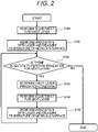
- FIG. 2 is a flowchart illustrating a flow of control of the additive modeling apparatus.
- Step S100 corresponds to a powder supply step of supplying the metal powder 2 to the modeling surface 4.
- control device 70 controls the operation of the laser systems 30 and 40 to perform the laser irradiation under the initial condition, and causes the first thermometers 36 and 46 and the second thermometer 50 to continuously measure the temperature of the modeling surface 4 after the coagulation of the molten pool 3, and records the temperature change (Step S101).
- This Step S101 corresponds to a laser irradiation step of melting the metal powder 2 at a portion forming the modeled object 5 in the metal powder 2 by irradiating the metal powder 2 supplied in the powder supply step with laser, and a temperature measurement step of measuring the temperature change of the modeling surface 4 after the beam irradiation in the laser irradiation step.
- Step S102 the control device 70 determines whether or not the modeling of the modeled object 5 is not completed and there is a laser irradiation plan for the next layer.
- Step S103 the process proceeds to Step S103.
- the processing is ended.
- control device 70 determines the irradiation condition for the next layer planned to be adjusted in Step S104 to be executed the next, based on the temperature change of the modeling surface 4 after the beam irradiation, which has been measured in Step S101 (Step S103) .
- This Step S103 corresponds to an irradiation condition determination step of determining the laser irradiation condition for the next layer.
- the irradiation condition determination step when it is determined that the temperature change is larger than the reference value in the measurement result in the temperature measurement step, it is possible to increase the heat input at the time of laser irradiation of the next layer of the region in accordance with the excess rate.
- the temperature change is equal to or less than the reference value, it is possible to reduce the heat input at the time of laser irradiation for the next layer in the region in accordance with the excess rate.
- Step S104 the control device 70 operates the powder supply mechanism to perform adjustment for forming the next layer.
- This Step S104 also corresponds to the powder supply step.
- Step S105 the control device 70 controls the operation of the laser systems 30 and 40 to perform laser irradiation to be performed based on the condition determined in Step S103.
- the control device 70 causes the first thermometers 36 and 46 and the second thermometer 50 to continuously measure the temperature of the modeling surface 4 after the laser irradiation, and records the temperature change (Step S105).
- This Step S105 also corresponds to the laser irradiation step and the temperature measurement step.
- Step S102 the process returns to Step S102, and the processing is continued until the entire laser irradiation plan is completed and the modeled object 5 is completed.
- the additive modeling apparatus 1 in the present embodiment described above includes the powder supply device that supplies metal powder 2 to the modeling surface 4, the laser systems 30 and 40 that melt the metal powder 2 at a predetermined position in the metal powder 2 supplied to the modeling surface 4, the first thermometers 36 and 46 and the second thermometer 50 that measure the temperature change in each region of the modeling surface 4, and the control device 70 that controls the laser systems 30 and 40.
- the control device 70 determines a laser irradiation condition for a next layer, based on the temperature change after beam irradiation of the modeling surface 4.
- the present invention it is possible to reflect the temperature monitoring result of the modeling surface in the control.
- the temperature of the modeling surface increased by the laser irradiation for each region and the cooling rate thereof can be monitored, and the formation of the molten pool formed by the laser irradiation and the form in which the molten pool is solidified thereafter can be observed.
- a region (region where the heat remains, region where the cooling rate is low) having poor heat conduction can be detected before modeling the next layer, and the irradiation condition can be changed based on the detection result.
- the condition can be changed to increase the amount of heat input in the region having the high thermal conductivity.
- control device 70 analyze the thermal conductivity of the modeled object 5 from the measurement results of the temperature change of the modeling surface 4 measured by the first thermometers 36 and 46, and the second thermometer 50 and the modeling volume of a certain number of layered layers from the front surface, and determines the laser irradiation condition for the next layer by using the thermal conductivity. Therefore, it is possible to stabilize the molten state even in a region where the thermal conductivity is poor (narrow), and perform more stable modeling.
- control device 70 can stabilize the molten state, improve the dimensional accuracy, and stabilize the cooling rate by determining at least one of the laser output, the laser scanning speed, and the laser hatching distance as the laser irradiation conditions, and can greatly contribute to stable modeling.
- the control device 70 can also stabilize the molten state, improve the dimensional accuracy, and stabilize the cooling rate by determining the standby time and the supply thickness of the metal powder 2 by the powder supply device as the laser irradiation conditions, and can greatly contribute to the stable modeling.
- the laser systems 30 and 40 include a plurality of lasers having different outputs, it is not necessary to adjust the laser output which is difficult to adjust even when changing the laser irradiation condition in accordance with the cooling state of the modeled object 5, and it is possible to efficiently perform modeling of the modeled object 5.
- control device 70 analyzes the thermal conductivity of the modeled object 5 from the measurement results of the temperature change of the modeling surface 4 and the modeling volume of a certain number of layered layers from the front surface.
- the control device 70 does not need to change the laser irradiation condition by using the laser having a smaller output at the time of laser irradiation for the next layer in the region where the thermal conductivity is analyzed to be smaller than the reference value or using the laser having a larger output at the time of laser irradiation for the next layer in the region where the thermal conductivity is analyzed to be equal to or greater than the reference value.
- control device 70 can use the more appropriate laser irradiation condition by reducing or increasing the amount of the heat input of the next layer in accordance with the excess rate, and thus it is possible to realize the modeling with higher efficiency.
- control device 70 compares the measurement results of the temperature change of the modeling surface 4 measured by the first thermometers 36 and 46, and the second thermometer 50 with the reference value, and omits the formation of the next layer in the region in which the measurement result is higher than the reference value. Thus, it is possible to stabilize the state of heat release and to further improve the modeling accuracy.
- the present invention is not limited to the above embodiment, and various modifications and applications are possible.
- the above-described embodiment is described in detail in order to explain the present invention in an easy-to-understand manner, and the above embodiment is not necessarily limited to a case including all the described configurations.
Landscapes
- Engineering & Computer Science (AREA)
- Chemical & Material Sciences (AREA)
- Manufacturing & Machinery (AREA)
- Materials Engineering (AREA)
- Automation & Control Theory (AREA)
- General Health & Medical Sciences (AREA)
- Health & Medical Sciences (AREA)
- Toxicology (AREA)
- Physics & Mathematics (AREA)
- Plasma & Fusion (AREA)
- Analytical Chemistry (AREA)
- Powder Metallurgy (AREA)
- Producing Shaped Articles From Materials (AREA)
Abstract
Description
- The present invention relates to an additive modeling apparatus and a method of controlling an additive modeling apparatus.
- Three-dimensional additive modeling techniques enable production of a product having a complicated shape, which has been impossible with the conventional processing technique such as cutting, and is expected to be applied in various fields. In recent years, various examinations have also been performed on an additive modeling method using powder.
- As a method of additive modeling, for example, a metal deposition method and a powder bed fusion method (powder bed method) are known.
- In the metal deposition method, an additive modeled object is obtained by repeating a step of forming a modeled layer by supplying a heated melt of metal powder to a predetermined position and then solidifying the heated melt.
- In the powder bed method, a thin powder layer is formed in a manner that metal powder is thinly spread on a base plate with a recoater or the like in accordance with predetermined modeling conditions (a beam irradiation condition, a thickness of a powder layer, and the like), based on slice data of a modeled object. Then, the powder layer is selectively melted by irradiating powder at a portion corresponding to the modeled object portion with a beam (for example, a laser beam or an electron beam). Then, the melting is stopped and coagulation is performed. Then, a three-dimensional modeled object is completed by repeated each of an operation of forming the powder layer and an operation of solidification by the beam irradiation.
- As an example of a device for additive manufacturing of the powder bed method,
PTL 1 discloses as follows. InPTL 1, a powder delivery mechanism, a powder recoating mechanism, an irradiation beam directing mechanism, a temperature control mechanism that measures a real-time temperature of a growing portion of a target object, a construction unit, a positioning mechanism, and a rotation mechanism are provided. The construction unit is attached to the positioning mechanism that provides the construction unit with independent motions in at least two dimensions. The construction unit is also attached to the rotation mechanism to rotate around and over a construction platform during manufacturing. In addition,PTL 1 includes a cycle of repeating a step of depositing powder on the construction platform, a step of forming a fused layer by irradiating a selected portion of the powder, and a step of measuring a real-time temperature of a selected portion of the fused layer. - PTL 1:
JP 2019-073796 A - In the three-dimensional additive modeling technique, there is a problem that the quality of the modeled object is not uniform.
- As a result of intensive examinations by the present inventors, it has become apparent that the state of heat dissipation varies for each region depending on the size of a laser irradiation region, a shape of a modeled object, and the quality of heat conduction, due to the shape and the like of the modeled object even under the same modeling condition, so that an excessive melting portion and an insufficient melting portion occur in one article.
- More specifically, for example, even in one layer, the laser irradiation diameter may vary between a complicated shape portion and a portion subjected to uniform modeling. Here, when these portions are compared with each other, it has become apparent that there is a problem that the amount of heat applied is different and the thermal conductivity (ease of escape of generated heat) is also different due to the shape and joining with the lower surface, so the quality of the modeled object obtained as a modeling result is different due to a difference in a heat history.
- For example, in the technique disclosed in
PTL 1, when the temperature of the growth portion is high, the modeling accuracy is improved by measuring the temperature of a fused portion in real time, such as reducing a laser output and reducing the accumulation of heat, and calculating the size based on the measured temperature. However, since the temperature of the fused portion (molten pool portion) is measured, heat dissipation is not considered. - Further, in the technique disclosed in
PTL 1, feedback control is performed by measuring the temperature of the molten pool, but the feedback control is not reflected in the subsequent layers. - The present invention has been made in view of such a problem, and an object thereof is to provide an additive modeling apparatus and a method of controlling the additive modeling apparatus capable of making the modeling quality of the entire modeled object uniform regardless of the shape of the modeled object.
- The present invention includes plural pieces of means for solving the above problems. According to an example of the present invention, an additive modeling apparatus includes a powder supply device that supplies powder to a modeling surface, a beam irradiation device that melts powder at a predetermined position in the powder supplied to the modeling surface, a temperature measurement device that measures a temperature change in each region of the modeling surface, and a control device that controls the beam irradiation device. The control device determines a beam irradiation condition for a next layer, based on the temperature change after beam irradiation of the modeling surface.
- According to the present disclosure, in additive modeling, it is possible to make the modeling quality of the entire modeled object, uniform regardless of the shape of the modeled object. Objects, configurations, and effects other than those described above will be clarified by the descriptions of the following embodiments.
-
- [
FIG. 1] FIG. 1 is a schematic diagram illustrating a configuration of an additive modeling apparatus according to an embodiment of the present invention. - [
FIG. 2] FIG. 2 is a flowchart illustrating a flow of control of the additive modeling apparatus in the embodiment of the present invention. - An embodiment of an additive modeling apparatus and a method of controlling the additive modeling apparatus according to the present invention will be described with reference to
FIGS. 1 and2 .FIG. 1 is a schematic diagram illustrating a configuration of an additive modeling apparatus according to an embodiment. - In the following embodiment, a form of irradiating metal powder with laser light will be described, but the material that can be used in additive modeling in the present invention is not limited to the metal powder, and may include a metal alloy, a polymer, or ceramic powder. Examples of a modeling material include a stainless steel alloy, cobalt-chromium, an aluminum alloy, a titanium alloy, a nickel-based superalloy, and a cobalt-based superalloy.
- In addition, a beam used to melt the material is not limited to a laser beam, and an electron beam can be used. In addition, the number of beams is not limited to two, and may be one or three or more.
- First, the overall configuration of the additive modeling apparatus will be described with reference to
FIG. 1 . - An
additive modeling apparatus 1 illustrated inFIG. 1 according to the present embodiment is an apparatus that models a modeledobject 5 by layering a modeling material based on design data (CAD data) of the modeledobject 5, and is an apparatus that manufactures the modeledobject 5 by a metal layering modeling method. - The
additive modeling apparatus 1 includes a powder supply device,laser systems control device 70, and the like, and temperature monitoring means for a modeled object. - The powder supply device is a device that supplies
metal powder 2 to amodeling surface 4 in amodeling space 10. The powder supply device includes asupply tank 20 for holding theunused metal powder 2, asupply mechanism 22 that supplies themetal powder 2 in thesupply tank 20 to arecoater 24, therecoater 24 that forms a powder layer (powder bed) made of themetal powder 2 for modeling on themodeling surface 4, a modeling surface up-down mechanism 26 that adjusts the position of themodeling surface 4, acollection tank 28 for collectingexcess metal powder 7, and the like. - The
laser systems metal powder 2 at a predetermined position (position corresponding to the shape of the modeled object 5) in themetal powder 2 supplied to themodeling surface 4. - In the present embodiment, the
laser systems laser system 30 has an output higher than an output of thelaser system 40 and has specifications in which high-speed scanning is possible. On the other hand, thelaser system 40 has a lower output and more precise specifications than those of thelaser system 30. - The
laser system 30 includes alaser scanner 32 that emits laser for melting themetal powder 2 at a predetermined position and alaser oscillator 34 that generates a laser. - The
laser scanner 32 is configured to be movable in an x-y plane parallel to a powder layer of themetal powder 2 formed on themodeling surface 4, and may adopt various known configurations movable in the x-y plane. The movement is not limited to the case of moving in the x-y plane, and the movement in the z direction toward or away from the powder layer can be made possible. In addition, it is also possible to adopt a configuration in which the powder layer is rotatable by 360 degrees about one vertical line perpendicular to the powder layer as a central axis. - The
laser system 40 includes alaser scanner 42 that emits laser for melting themetal powder 2 and alaser oscillator 44 that generates laser. - The
first thermometers modeling surface 4, and measure the temperature change by continuously measuring the temperature in the respective regions of themodeling surface 4. - The
first thermometer 36 is installed so that a measurement direction of thefirst thermometer 36 is coaxial with laser emitted from thelaser scanner 32 of thelaser system 30. For example, thefirst thermometer 36 can be set as a radiation thermometer that measures the intensity of infrared rays or visible rays radiated from an object and measures the temperature of the object. Preferably, it is possible to measure the temperature change of themodeling surface 4 after coagulation of themetal powder 2, not a portion of amolten pool 3 formed by melting themetal powder 2 by laser irradiation, at the timing before formation of the next layer. - It is also possible to measure the temperature change at the portion of the
molten pool 3. - The
first thermometer 46 is installed so that a measurement direction of thefirst thermometer 46 is coaxial with laser emitted from thelaser scanner 42 of thelaser system 40. Thefirst thermometer 46 has the same specifications as those of thefirst thermometer 36 described above, and details thereof will be omitted. - In the present embodiment, a
second thermometer 50 is attached to thelaser oscillator 44 of thelaser system 40. Similar to thefirst thermometers second thermometer 50 is a thermometer that measures the temperature in each region of themodeling surface 4, and measures the temperature change by continuously measuring the temperature in each region of themodeling surface 4. Similarly, preferably, it is possible to assume that the temperature change of themodeling surface 4 after coagulation of themetal powder 2, not a portion of amolten pool 3 formed by melting themetal powder 2 by laser irradiation, is measured at the timing before formation of the next layer. - The
second thermometer 50 desirably has specifications capable of measuring the temperature of themodeling surface 4 after laser irradiation in a range wider than that of thefirst thermometers metal powder 2. For example, thesecond thermometer 50 can be set as a radiation thermometer that measures the temperature of an object by measuring the intensity of infrared rays or visible rays emitted from the object. - A
third thermometer 60 is a thermometer that measures the temperature of the lower surface portion of themodeling space 10, and includes, for example, a thermocouple. - The temperature measurement results of the
first thermometers second thermometer 50, and thethird thermometer 60 are input to thecontrol device 70. - The
control device 70 is a device that controls the operations of thesupply mechanism 22 of the powder supply device, therecoater 24, and thelaser systems control device 70, and the like. Thecontrol device 70 realizes each function described later in a manner that the CPU performs an operation (data calculation and the like) in accordance with commands of a modeling condition program determined based on the three-dimensional shape of the modeledobject 5 loaded into the storage device. - Control processing of the operation performed by the
control device 70 may be integrated into one program, may be divided into a plurality of programs, or may be a combination thereof. - A portion or the entirety of the program may be implemented by dedicated hardware or may be modularized. Furthermore, various programs may be installed in each device by a program distribution server or an external storage medium.
- Furthermore, independent devices are connected to each other via a wired or wireless network, or two or more programs may be integrated.
- In the present embodiment, the
control device 70 includes, as functional blocks thereof, an irradiation-region thermalconductivity analysis unit 72, a supplydevice control unit 74, and a lasersystem control unit 76. The irradiation-region thermalconductivity analysis unit 72 determines a laser irradiation condition for the next layer based on the temperature change of themodeling surface 4 after beam irradiation, which is input from thefirst thermometers second thermometer 50. The supplydevice control unit 74 controls the operation of the powder supply device when the next layer is formed based on the laser irradiation condition determined by the irradiation-region thermalconductivity analysis unit 72. The lasersystem control unit 76 controls the operations of thelaser systems conductivity analysis unit 72. - In the irradiation-region thermal
conductivity analysis unit 72 in the present embodiment, the temperature change of themodeling surface 4 after laser irradiation input from thefirst thermometers second thermometer 50 is compared with the reference value, and the laser irradiation condition of the next layer can be determined based on the comparison result. A measurement value of thethird thermometer 60 can also be used. - In particular, in the
control device 70 in the present embodiment, for the purpose of stabilizing the molten state, improving the dimensional accuracy, and stabilizing the cooling rate, it is possible to determine at least one of conditions of the laser output, the laser scanning speed, and the laser hatching distance, as the laser irradiation conditions. In addition, as the laser irradiation conditions, the standby time until the next layer is irradiated, and the supply thickness of themetal powder 2 by the powder supply device can also be determined. - Furthermore, the
control device 70 can analyze the thermal conductivity of the modeledobject 5 from the measurement result of the temperature change of themodeling surface 4, which has been measured by thefirst thermometers second thermometer 50 and the modeling volume of a certain number of layered layers from the front surface, and determine the laser irradiation condition for the next layer by using the thermal conductivity. - For example, the
control device 70 can analyze the thermal conductivity of the modeledobject 5 from the measurement result of the temperature change of themodeling surface 4 and the modeling volume of a certain number of layered layers from the front surface, and can determine the condition using the laser (laser system 40) having a smaller output at the time of laser irradiation of the next layer in order for the modeledobject 5 to be modeled by reducing a heat input because an overmelted state due to heat from the previous layer is likely to occur in a region where the thermal conductivity is analyzed to be smaller than the reference value. - On the other hand, when laser irradiation is performed on the next layer in the region analyzed to have thermal conductivity that is equal to or greater than the reference value, the laser (laser system 30) having a larger output is used. At this time, the laser irradiation conditions such as the output, the scanning speed, the hatching distance, the standby time, and the supply thickness of the
metal powder 2 can be determined so as to increase the amount of heat input, as the difference from the reference value increases. - Furthermore, the
control device 70 can compare the measurement results of the temperature changes of themodeling surface 4, which have been measured by thefirst thermometers second thermometer 50 with the reference value, and omit the descriptions of the formation of the next layer in the region in which the measurement result is higher than the reference value. - For example, in the region where the measurement result is higher than the reference value, that is, in a region where the thermal conductivity is poor, modeling can be performed by setting the powder spread thickness as a plurality of times (in a region in which the thermal conductivity is poor, one irradiation is skipped, and laser irradiation at a time of becoming 40 µm) of normal modeling (for example, thickness of 20 µm), performing change to the laser irradiation condition in which the plurality of times of powder thicknesses can be molted.
- Next, a method of controlling the
additive modeling apparatus 1 that manufactures the modeledobject 5 by the additive modeling according to the present embodiment will be described with reference toFIG. 2. FIG. 2 is a flowchart illustrating a flow of control of the additive modeling apparatus. - First, the
control device 70 starts processing and operates the powder supply device to perform adjustment for forming the first layer as illustrated inFIG. 2 (step S100). This Step S100 corresponds to a powder supply step of supplying themetal powder 2 to themodeling surface 4. - Then, the
control device 70 controls the operation of thelaser systems first thermometers second thermometer 50 to continuously measure the temperature of themodeling surface 4 after the coagulation of themolten pool 3, and records the temperature change (Step S101). - This Step S101 corresponds to a laser irradiation step of melting the
metal powder 2 at a portion forming the modeledobject 5 in themetal powder 2 by irradiating themetal powder 2 supplied in the powder supply step with laser, and a temperature measurement step of measuring the temperature change of themodeling surface 4 after the beam irradiation in the laser irradiation step. - Then, the
control device 70 determines whether or not the modeling of the modeledobject 5 is not completed and there is a laser irradiation plan for the next layer (Step S102). When it is determined that there is the irradiation plan for the next layer, the process proceeds to Step S103. On the other hand, when it is determined that there is no irradiation plan, that is, when it is determined that the modeling of the modeled object has been completed, the processing is ended. - Then, the
control device 70 determines the irradiation condition for the next layer planned to be adjusted in Step S104 to be executed the next, based on the temperature change of themodeling surface 4 after the beam irradiation, which has been measured in Step S101 (Step S103) . - This Step S103 corresponds to an irradiation condition determination step of determining the laser irradiation condition for the next layer. In the irradiation condition determination step, when it is determined that the temperature change is larger than the reference value in the measurement result in the temperature measurement step, it is possible to increase the heat input at the time of laser irradiation of the next layer of the region in accordance with the excess rate. When it is determined that the temperature change is equal to or less than the reference value, it is possible to reduce the heat input at the time of laser irradiation for the next layer in the region in accordance with the excess rate.
- Then, the
control device 70 operates the powder supply mechanism to perform adjustment for forming the next layer (Step S104). This Step S104 also corresponds to the powder supply step. - Then, the
control device 70 controls the operation of thelaser systems control device 70 causes thefirst thermometers second thermometer 50 to continuously measure the temperature of themodeling surface 4 after the laser irradiation, and records the temperature change (Step S105). This Step S105 also corresponds to the laser irradiation step and the temperature measurement step. - Then, the process returns to Step S102, and the processing is continued until the entire laser irradiation plan is completed and the modeled
object 5 is completed. - Next, the effect of the present embodiment will be described.
- The
additive modeling apparatus 1 in the present embodiment described above includes the powder supply device that suppliesmetal powder 2 to themodeling surface 4, thelaser systems metal powder 2 at a predetermined position in themetal powder 2 supplied to themodeling surface 4, thefirst thermometers second thermometer 50 that measure the temperature change in each region of themodeling surface 4, and thecontrol device 70 that controls thelaser systems control device 70 determines a laser irradiation condition for a next layer, based on the temperature change after beam irradiation of themodeling surface 4. - According to the present invention, it is possible to reflect the temperature monitoring result of the modeling surface in the control. In particular, the temperature of the modeling surface increased by the laser irradiation for each region and the cooling rate thereof can be monitored, and the formation of the molten pool formed by the laser irradiation and the form in which the molten pool is solidified thereafter can be observed. Thus, in the
modeling surface 4 in which themolten pool 3 is solidified, a region (region where the heat remains, region where the cooling rate is low) having poor heat conduction can be detected before modeling the next layer, and the irradiation condition can be changed based on the detection result. On the contrary, the condition can be changed to increase the amount of heat input in the region having the high thermal conductivity. - As a result, even in the modeled
object 5 in which the area and shape of the laser irradiation region of each layer are different, it is possible to improve the dimension accuracy of the modeledobject 5 as compared with the conventional art by optimizing the laser irradiation conditions in all layers during modeling and suppressing excessive melting, and it is possible to stabilize the modeling quality of the modeledobject 5 as compared to the conventional technique by controlling the cooling rate. Thus, it is possible to perform the entire modeling with uniform quality. - Furthermore, the
control device 70 analyze the thermal conductivity of the modeledobject 5 from the measurement results of the temperature change of themodeling surface 4 measured by thefirst thermometers second thermometer 50 and the modeling volume of a certain number of layered layers from the front surface, and determines the laser irradiation condition for the next layer by using the thermal conductivity. Therefore, it is possible to stabilize the molten state even in a region where the thermal conductivity is poor (narrow), and perform more stable modeling. - Furthermore, the
control device 70 can stabilize the molten state, improve the dimensional accuracy, and stabilize the cooling rate by determining at least one of the laser output, the laser scanning speed, and the laser hatching distance as the laser irradiation conditions, and can greatly contribute to stable modeling. - The
control device 70 can also stabilize the molten state, improve the dimensional accuracy, and stabilize the cooling rate by determining the standby time and the supply thickness of themetal powder 2 by the powder supply device as the laser irradiation conditions, and can greatly contribute to the stable modeling. - Furthermore, since the
laser systems object 5, and it is possible to efficiently perform modeling of the modeledobject 5. - Furthermore, the
control device 70 analyzes the thermal conductivity of the modeledobject 5 from the measurement results of the temperature change of themodeling surface 4 and the modeling volume of a certain number of layered layers from the front surface. Thecontrol device 70 does not need to change the laser irradiation condition by using the laser having a smaller output at the time of laser irradiation for the next layer in the region where the thermal conductivity is analyzed to be smaller than the reference value or using the laser having a larger output at the time of laser irradiation for the next layer in the region where the thermal conductivity is analyzed to be equal to or greater than the reference value. Thus, it is possible to realize the modeling with higher efficiency. - In particular, the
control device 70 can use the more appropriate laser irradiation condition by reducing or increasing the amount of the heat input of the next layer in accordance with the excess rate, and thus it is possible to realize the modeling with higher efficiency. - Furthermore, the
control device 70 compares the measurement results of the temperature change of themodeling surface 4 measured by thefirst thermometers second thermometer 50 with the reference value, and omits the formation of the next layer in the region in which the measurement result is higher than the reference value. Thus, it is possible to stabilize the state of heat release and to further improve the modeling accuracy. - The present invention is not limited to the above embodiment, and various modifications and applications are possible. The above-described embodiment is described in detail in order to explain the present invention in an easy-to-understand manner, and the above embodiment is not necessarily limited to a case including all the described configurations.
-
- 1
- additive modeling apparatus
- 2
- metal powder
- 3
- molten pool
- 4
- modeling surface
- 5
- modeled object
- 7
- used metal powder
- 10
- modeling space
- 20
- supply tank (powder supply device)
- 22
- supply mechanism (powder supply device)
- 24
- recoater (powder supply device)
- 26
- modeling tank (powder supply device)
- 28
- collection tank
- 30
- laser system (beam irradiation device)
- 32
- laser scanner
- 34
- laser oscillator
- 36
- first thermometer (temperature measurement device)
- 40
- laser system (beam irradiation device)
- 42
- laser scanner
- 44
- laser oscillator
- 46
- first thermometer (temperature measurement device)
- 50
- second thermometer (temperature measurement device)
- 60
- third thermometer
- 70
- control device
- 72
- irradiation-region thermal conductivity analysis unit
- 74
- supply-device control unit
- 76
- laser-system control unit
Claims (13)
- An additive modeling apparatus comprising:a powder supply device that supplies powder to a modeling surface;a beam irradiation device that melts powder at a predetermined position in the powder supplied to the modeling surface;a temperature measurement device that measures a temperature change in each region of the modeling surface; anda control device that controls the beam irradiation device,wherein the control device determines a beam irradiation condition for a next layer, based on the temperature change after beam irradiation of the modeling surface.
- The additive modeling apparatus according to claim 1, wherein the control device analyzes a thermal conductivity of a modeled object from a measurement result of the temperature change of the modeling surface, which has been measured by the temperature measurement device and a modeling volume of a certain number of layered layers from a front surface, and determines the beam irradiation condition for the next layer by using the thermal conductivity.
- The additive modeling apparatus according to claim 1, wherein the control device determines at least one condition among an output of a beam, a scanning speed of the beam, and a hatching distance of the beam, as the beam irradiation condition.
- The additive modeling apparatus according to claim 1, wherein the control device also determines a standby time and a supply thickness of the powder by the powder supply device, as the beam irradiation condition.
- The additive modeling apparatus according to claim 1, wherein the beam irradiation device includes a plurality of beams having different outputs.
- The additive modeling apparatus according to claim 5, wherein the control device analyzes a thermal conductivity of a modeled object from a measurement result of the temperature change of the modeling surface and a modeling volume of a certain number of layered layers from a front surface, and uses a beam having a smaller output at a time of beam irradiation of the next layer in a region where the thermal conductivity is analyzed to be smaller than a reference value.
- The additive modeling apparatus according to claim 6, wherein the control device reduces heat input at the time of beam irradiation for the next layer in the region in accordance with an excess rate.
- The additive modeling apparatus according to claim 5, wherein the control device analyzes a thermal conductivity of a modeled object from a measurement result of the temperature change of the modeling surface and a modeling volume of a certain number of layered layers from a front surface, and uses a beam having a larger output at a time of beam irradiation of the next layer in a region where the thermal conductivity is analyzed to be equal to or greater than a reference value.
- The additive modeling apparatus according to claim 8, wherein the control device increases heat input at the time of beam irradiation for the next layer in the region in accordance with an excess rate.
- The additive modeling apparatus according to claim 1, wherein the control device compares a measurement result of the temperature change of the modeling surface, which has been measured by the temperature measurement device, to a reference value, and omits formation of the next layer in a region where the measurement result is higher than the reference value.
- A method of controlling an additive modeling apparatus that manufactures a modeled object by additive modeling, the method comprising:a powder supply step of supplying powder to a modeling surface;a beam irradiation step of melting powder at a portion forming the modeled object in the powder by irradiating the powder supplied in the powder supply step with a beam;a temperature measurement step of measuring a temperature change of the modeling surface after the beam irradiation in the beam irradiation step; andan irradiation condition determination step of determining a beam irradiation condition in a next layer, based on the temperature change after the beam irradiation of the modeling surface, which has been measured in the temperature measurement step.
- The method of controlling an additive modeling apparatus according to claim 11, wherein in the irradiation condition determination step, when it is determined that the temperature change is equal to or less than a reference value in the measurement result in the temperature measurement step, a heat input at a time of beam irradiation of the next layer in the region is reduced in accordance with an excess rate.
- The method of controlling an additive modeling apparatus according to claim 11, wherein in the irradiation condition determination step, when it is determined that the temperature change is greater than a reference value in the measurement result in the temperature measurement step, a heat input at a time of beam irradiation of the next layer in the region is increased in accordance with an excess rate.
Applications Claiming Priority (2)
| Application Number | Priority Date | Filing Date | Title |
|---|---|---|---|
| JP2020043883A JP7446874B2 (en) | 2020-03-13 | 2020-03-13 | Additive printing device and control method for additive printing device |
| PCT/JP2020/034127 WO2021181727A1 (en) | 2020-03-13 | 2020-09-09 | Additive modeling device and method for controlling additive modeling device |
Publications (2)
| Publication Number | Publication Date |
|---|---|
| EP4119263A1 true EP4119263A1 (en) | 2023-01-18 |
| EP4119263A4 EP4119263A4 (en) | 2024-05-15 |
Family
ID=77671497
Family Applications (1)
| Application Number | Title | Priority Date | Filing Date |
|---|---|---|---|
| EP20924892.1A Pending EP4119263A4 (en) | 2020-03-13 | 2020-09-09 | Additive modeling device and method for controlling additive modeling device |
Country Status (3)
| Country | Link |
|---|---|
| EP (1) | EP4119263A4 (en) |
| JP (1) | JP7446874B2 (en) |
| WO (1) | WO2021181727A1 (en) |
Families Citing this family (1)
| Publication number | Priority date | Publication date | Assignee | Title |
|---|---|---|---|---|
| CN117943559B (en) * | 2024-03-26 | 2024-07-23 | 中国航发沈阳黎明航空发动机有限责任公司 | Hollow adjustable blade additive manufacturing method based on combined substrate |
Family Cites Families (6)
| Publication number | Priority date | Publication date | Assignee | Title |
|---|---|---|---|---|
| ES2983485T3 (en) * | 2015-11-16 | 2024-10-23 | Renishaw Plc | Additive manufacturing method and apparatus |
| WO2017201120A1 (en) * | 2016-05-17 | 2017-11-23 | Board Of Regents, The University Of Texas System | Real-time laser control for powder bed fusion |
| CN109421267A (en) * | 2017-09-04 | 2019-03-05 | 东台精机股份有限公司 | three-dimensional printing device for dust recovery and operation method thereof |
| CN107807568B (en) * | 2017-10-27 | 2020-08-04 | 中国电子产品可靠性与环境试验研究所 | Additive manufacturing monitoring system, method, apparatus and additive manufacturing equipment |
| EP3808541A4 (en) * | 2018-06-13 | 2022-05-11 | Nikon Corporation | CALCULATION DEVICE, DETECTION SYSTEM, FORMING DEVICE, CALCULATION METHOD, DETECTION METHOD, FORMING METHOD, CALCULATION PROGRAM, DETECTION PROGRAM AND FORMING PROGRAM |
| CN109483888B (en) * | 2018-12-03 | 2020-05-19 | 西安交通大学 | Laser cladding additive forming online monitoring device and look-ahead-feedback control method |
-
2020
- 2020-03-13 JP JP2020043883A patent/JP7446874B2/en active Active
- 2020-09-09 WO PCT/JP2020/034127 patent/WO2021181727A1/en not_active Ceased
- 2020-09-09 EP EP20924892.1A patent/EP4119263A4/en active Pending
Also Published As
| Publication number | Publication date |
|---|---|
| JP2021143405A (en) | 2021-09-24 |
| EP4119263A4 (en) | 2024-05-15 |
| WO2021181727A1 (en) | 2021-09-16 |
| JP7446874B2 (en) | 2024-03-11 |
Similar Documents
| Publication | Publication Date | Title |
|---|---|---|
| EP3741481B1 (en) | Additive manufacturing with adjusted cooling responsive to thermal characteristic of workpiece | |
| US10766199B2 (en) | Three-dimensional additive manufacturing device | |
| KR101820553B1 (en) | Method for production of a three-dimensional body | |
| JP6626033B2 (en) | Apparatus and method for selective laser sintering of objects with voids | |
| JP2018536560A (en) | Machine control for additive manufacturing processes and equipment | |
| US20160326880A1 (en) | An additive manufacturing system utilizing an epitaxy process and method of operation | |
| WO2019206903A1 (en) | Method and arrangement for producing a workpiece by using adaptive closed-loop control of additive manufacturing techniques | |
| JP2017140828A (en) | A novel method for calibrating laser additive manufacturing processes | |
| US20230405681A1 (en) | Powder bed fusion methods and related apparatus | |
| Boddu et al. | Control of laser cladding for rapid prototyping--a review | |
| EP3587005A1 (en) | Control method for layerwise additive manufacturing, computer program product and control apparatus | |
| US11846928B2 (en) | Method for irradiating a powder layer in additive production using continuously defined production parameters | |
| US20240082920A1 (en) | Thermal stress and substrate damage reducing additive manufacturing method | |
| EP3498401A1 (en) | Method of additively manufacturing a component, an apparatus and computer program product | |
| CN118690970B (en) | Artificial intelligence-based additive manufacturing process optimization method and system | |
| Heilemann et al. | Effect of heat accumulation on the single track formation during laser metal deposition and development of a framework for analyzing new process strategies | |
| EP4119263A1 (en) | Additive modeling device and method for controlling additive modeling device | |
| JP2019507040A (en) | Additive manufacturing method and system | |
| CN110545940B (en) | Method for manufacturing workpiece, method for establishing correction parameter and storage medium | |
| CN117399647B (en) | Metal material processing control optimization method based on 3D printing | |
| Ueda et al. | Intelligent process planning and control of DED (directed energy deposition) for rapid manufacturing | |
| JP2021172863A (en) | Method of monitoring additive manufacturing process, additive manufacturing method, apparatus for monitoring additive manufacturing process and additive manufacturing apparatus | |
| EP2377641A2 (en) | Method and apparatus for Manufacturing a Component | |
| US20180154445A1 (en) | Device for controlling additive manufacturing machinery | |
| Liao et al. | Vision-based real-time molten pool monitoring for Electron Beam Freeform Fabrication |
Legal Events
| Date | Code | Title | Description |
|---|---|---|---|
| STAA | Information on the status of an ep patent application or granted ep patent |
Free format text: STATUS: THE INTERNATIONAL PUBLICATION HAS BEEN MADE |
|
| PUAI | Public reference made under article 153(3) epc to a published international application that has entered the european phase |
Free format text: ORIGINAL CODE: 0009012 |
|
| STAA | Information on the status of an ep patent application or granted ep patent |
Free format text: STATUS: REQUEST FOR EXAMINATION WAS MADE |
|
| 17P | Request for examination filed |
Effective date: 20220823 |
|
| AK | Designated contracting states |
Kind code of ref document: A1 Designated state(s): AL AT BE BG CH CY CZ DE DK EE ES FI FR GB GR HR HU IE IS IT LI LT LU LV MC MK MT NL NO PL PT RO RS SE SI SK SM TR |
|
| DAV | Request for validation of the european patent (deleted) | ||
| DAX | Request for extension of the european patent (deleted) | ||
| REG | Reference to a national code |
Ref country code: DE Ref legal event code: R079 Free format text: PREVIOUS MAIN CLASS: B22F0003105000 Ipc: B22F0010366000 |
|
| A4 | Supplementary search report drawn up and despatched |
Effective date: 20240415 |
|
| RIC1 | Information provided on ipc code assigned before grant |
Ipc: B33Y 50/02 20150101ALI20240409BHEP Ipc: B33Y 30/00 20150101ALI20240409BHEP Ipc: B33Y 10/00 20150101ALI20240409BHEP Ipc: B28B 1/30 20060101ALI20240409BHEP Ipc: B22F 3/16 20060101ALI20240409BHEP Ipc: B22F 3/105 20060101ALI20240409BHEP Ipc: B22F 12/45 20210101ALI20240409BHEP Ipc: B22F 12/90 20210101ALI20240409BHEP Ipc: B22F 10/28 20210101ALI20240409BHEP Ipc: B22F 10/36 20210101ALI20240409BHEP Ipc: B22F 10/368 20210101ALI20240409BHEP Ipc: B22F 10/366 20210101AFI20240409BHEP |