EP4119250A1 - Method for manufacturing pressed component, metal plate for press-molding, and high-tensile steel plate - Google Patents
Method for manufacturing pressed component, metal plate for press-molding, and high-tensile steel plate Download PDFInfo
- Publication number
- EP4119250A1 EP4119250A1 EP21768026.3A EP21768026A EP4119250A1 EP 4119250 A1 EP4119250 A1 EP 4119250A1 EP 21768026 A EP21768026 A EP 21768026A EP 4119250 A1 EP4119250 A1 EP 4119250A1
- Authority
- EP
- European Patent Office
- Prior art keywords
- metal sheet
- forming
- pressed component
- longitudinal direction
- curved
- Prior art date
- Legal status (The legal status is an assumption and is not a legal conclusion. Google has not performed a legal analysis and makes no representation as to the accuracy of the status listed.)
- Pending
Links
- 229910052751 metal Inorganic materials 0.000 title claims abstract description 129
- 239000002184 metal Substances 0.000 title claims abstract description 129
- 238000000034 method Methods 0.000 title claims abstract description 44
- 238000004519 manufacturing process Methods 0.000 title claims abstract description 25
- 229910000831 Steel Inorganic materials 0.000 title claims description 11
- 239000010959 steel Substances 0.000 title claims description 11
- 238000000465 moulding Methods 0.000 title 1
- 239000011324 bead Substances 0.000 claims abstract description 179
- 230000015572 biosynthetic process Effects 0.000 claims description 9
- 230000037303 wrinkles Effects 0.000 abstract description 62
- 239000000463 material Substances 0.000 description 26
- 230000000052 comparative effect Effects 0.000 description 10
- 238000005452 bending Methods 0.000 description 9
- 238000012545 processing Methods 0.000 description 8
- 230000006835 compression Effects 0.000 description 7
- 238000007906 compression Methods 0.000 description 7
- 230000000694 effects Effects 0.000 description 5
- 238000011156 evaluation Methods 0.000 description 5
- 230000008602 contraction Effects 0.000 description 4
- 230000007547 defect Effects 0.000 description 3
- 230000004048 modification Effects 0.000 description 3
- 238000012986 modification Methods 0.000 description 3
- 229910000838 Al alloy Inorganic materials 0.000 description 2
- 238000013459 approach Methods 0.000 description 2
- 238000005516 engineering process Methods 0.000 description 2
- 230000006872 improvement Effects 0.000 description 2
- 238000003825 pressing Methods 0.000 description 2
- 238000009751 slip forming Methods 0.000 description 2
- 230000001131 transforming effect Effects 0.000 description 2
- 230000037331 wrinkle reduction Effects 0.000 description 2
- 238000004458 analytical method Methods 0.000 description 1
- 239000002131 composite material Substances 0.000 description 1
- 230000008569 process Effects 0.000 description 1
- 230000001105 regulatory effect Effects 0.000 description 1
- 230000000452 restraining effect Effects 0.000 description 1
- 239000002436 steel type Substances 0.000 description 1
- 230000001629 suppression Effects 0.000 description 1
- 230000009466 transformation Effects 0.000 description 1
Images


Classifications
-
- B—PERFORMING OPERATIONS; TRANSPORTING
- B21—MECHANICAL METAL-WORKING WITHOUT ESSENTIALLY REMOVING MATERIAL; PUNCHING METAL
- B21D—WORKING OR PROCESSING OF SHEET METAL OR METAL TUBES, RODS OR PROFILES WITHOUT ESSENTIALLY REMOVING MATERIAL; PUNCHING METAL
- B21D17/00—Forming single grooves in sheet metal or tubular or hollow articles
- B21D17/02—Forming single grooves in sheet metal or tubular or hollow articles by pressing
-
- B—PERFORMING OPERATIONS; TRANSPORTING
- B21—MECHANICAL METAL-WORKING WITHOUT ESSENTIALLY REMOVING MATERIAL; PUNCHING METAL
- B21D—WORKING OR PROCESSING OF SHEET METAL OR METAL TUBES, RODS OR PROFILES WITHOUT ESSENTIALLY REMOVING MATERIAL; PUNCHING METAL
- B21D22/00—Shaping without cutting, by stamping, spinning, or deep-drawing
- B21D22/20—Deep-drawing
- B21D22/26—Deep-drawing for making peculiarly, e.g. irregularly, shaped articles
-
- B—PERFORMING OPERATIONS; TRANSPORTING
- B21—MECHANICAL METAL-WORKING WITHOUT ESSENTIALLY REMOVING MATERIAL; PUNCHING METAL
- B21D—WORKING OR PROCESSING OF SHEET METAL OR METAL TUBES, RODS OR PROFILES WITHOUT ESSENTIALLY REMOVING MATERIAL; PUNCHING METAL
- B21D22/00—Shaping without cutting, by stamping, spinning, or deep-drawing
- B21D22/20—Deep-drawing
-
- B—PERFORMING OPERATIONS; TRANSPORTING
- B21—MECHANICAL METAL-WORKING WITHOUT ESSENTIALLY REMOVING MATERIAL; PUNCHING METAL
- B21D—WORKING OR PROCESSING OF SHEET METAL OR METAL TUBES, RODS OR PROFILES WITHOUT ESSENTIALLY REMOVING MATERIAL; PUNCHING METAL
- B21D22/00—Shaping without cutting, by stamping, spinning, or deep-drawing
- B21D22/20—Deep-drawing
- B21D22/206—Deep-drawing articles from a strip in several steps, the articles being coherent with the strip during the operation
-
- B—PERFORMING OPERATIONS; TRANSPORTING
- B21—MECHANICAL METAL-WORKING WITHOUT ESSENTIALLY REMOVING MATERIAL; PUNCHING METAL
- B21D—WORKING OR PROCESSING OF SHEET METAL OR METAL TUBES, RODS OR PROFILES WITHOUT ESSENTIALLY REMOVING MATERIAL; PUNCHING METAL
- B21D24/00—Special deep-drawing arrangements in, or in connection with, presses
- B21D24/005—Multi-stage presses
-
- B—PERFORMING OPERATIONS; TRANSPORTING
- B21—MECHANICAL METAL-WORKING WITHOUT ESSENTIALLY REMOVING MATERIAL; PUNCHING METAL
- B21D—WORKING OR PROCESSING OF SHEET METAL OR METAL TUBES, RODS OR PROFILES WITHOUT ESSENTIALLY REMOVING MATERIAL; PUNCHING METAL
- B21D11/00—Bending not restricted to forms of material mentioned in only one of groups B21D5/00, B21D7/00, B21D9/00; Bending not provided for in groups B21D5/00 - B21D9/00; Twisting
- B21D11/08—Bending by altering the thickness of part of the cross-section of the work
Definitions
- the present invention relates to a technology for manufacturing a pressed component including manufacturing a pressed component having a cross section, such as a U-shaped cross section, a hat-shaped cross section, or an L-shaped cross section, having at least a top sheet portion and a side wall portion continuous to at least one side in the width direction of the top sheet portion and having one or two or more curved portions in which the top sheet portion is curved to project or to be recessed in the sheet thickness direction of the top sheet portion in a side view along the longitudinal direction in the direction intersecting the cross section.
- a cross section such as a U-shaped cross section, a hat-shaped cross section, or an L-shaped cross section, having at least a top sheet portion and a side wall portion continuous to at least one side in the width direction of the top sheet portion and having one or two or more curved portions in which the top sheet portion is curved to project or to be recessed in the sheet thickness direction of the top sheet portion in a side view along the longitudinal direction in the direction intersecting the cross section
- a large number of pressed components including automobiles and home appliances are produced by transforming a flat metal sheet into various shapes.
- press forming (pressing) including transforming a metal sheet using a press machine and a die has been widely used for the production of the pressed components.
- a metal sheet before work is flat, and therefore the transformation of the metal sheet into a complicated three-dimensional shape requires expansion and contraction of the metal sheet according to a three-dimensional shape.
- the more complicated the shape of the pressed component the more difficult it is to expand and contract the metal sheet according to the three-dimensional shape.
- the metal sheet to be press formed contains a high-tensile steel sheet or an aluminum alloy sheet having a tensile strength of 590 MPa or more, for example, and a member difficult to form having poor ductility or a poor Lankford Value is adopted as the metal sheet, the above-described problems are likely to occur.
- the metal sheet In the press forming, when the metal sheet cannot be expanded and contracted according to the three-dimensional shape, forming defects, such as cracks or wrinkles, are generated in the metal sheet. More specifically, when the metal sheet is transformed into a three-dimensional shape, the metal sheet has no choice but to expand in a site where the length of the metal sheet is insufficient and the shortage in length is not compensated from the surroundings. Then, when the metal sheet is stretched beyond the ductility of the metal sheet itself, cracks are generated. On the other hand, when the metal sheet is transformed into a three-dimensional shape, wrinkles tend to be generated in a case where the length of the metal sheet needs to be shortened or in a site where the length of the metal sheet excessively flows from the surroundings.
- Examples of a component shape difficult to achieve by press forming include a press formed component having a cross section having a top sheet portion, a vertical wall portion continuous to the top sheet portion, and a flange portion formed continuously to the vertical wall portion and having one or two or more curved shapes in a side view along the longitudinal direction.
- the top sheet portion is restrained by the pad, and therefore the tensile deformation or compression deformation in the top sheet portion can be suppressed.
- the flange portion is not restrained, and therefore the metal sheet tends to have wrinkles under the influence of the tensile deformation or the compression deformation.
- the top sheet portion is not restrained, and therefore the metal sheet tends to have wrinkles under the influence of the tensile deformation or the compression deformation. Therefore, the generation of wrinkles cannot be suppressed unless the tensile/compression deformation of the metal sheet occurring in the entire component shape are taken into consideration.
- the top sheet portion is restrained by the pad and the flange portion is also restrained by the blank holder, so that the tensile/compression deformation in both the top sheet portion and the flange portion can be suppressed.
- it is necessary to restrain a material with the pad in addition to a normal drawing step, and thus the productivity is poor.
- the method described in PTL 1 has a high die cost.
- the present invention has been made focusing on the above-described points. It is an object of the present invention to suppress the generation of wrinkles by a simple means in press forming into a pressed component shape having one or two or more curved portions in which the top sheet portion is curved to project or to be recessed in a side view.
- the present inventors have studied a press method capable of forming a press formed component without generating cracks or wrinkles and not requiring a complicated die configuration, the press formed component having a hat-shaped cross section including a top sheet portion, vertical wall portions formed on both sides of the top sheet portion, and a flange portion formed continuously to the vertical wall portions and having curved shapes in the upper and lower sides in a side view. Then, the present inventors have obtained the following findings.
- the present invention has been made based on the above-described findings.
- one aspect of the present invention is a method for manufacturing a pressed component including forming a metal sheet into a pressed component shape having: a cross section having a top sheet portion and a side wall portion continuous to at least one side in the width direction of the top sheet portion via a first bent portion; and having one or two or more curved portions in which the top sheet portion is curved to project or to be recessed in a side view along the longitudinal direction in the direction intersecting the cross section, the method which includes: a first preliminary forming step having a step of forming, to the metal sheet, a first bead continuously or partially extending along the longitudinal direction at a position where the first bent portion is formed; and a first component forming step of forming the metal sheet after the first preliminary forming step into the pressed component shape.
- One aspect of the present invention is a method for manufacturing a pressed component including forming a metal sheet into a pressed component shape having: a cross section having a top sheet portion, a side wall portion continuous to at least one side in the width direction of the top sheet portion via a first bent portion, and a flange portion continuous to the side wall portion via a second bent portion; and having one or two or more curved portions in which the top sheet portion is curved to project or to be recessed in a side view along the longitudinal direction in the direction intersecting the cross section, the method which includes: a second preliminary forming step having a step of forming, to the metal sheet, a second bead continuously or partially extending along the longitudinal direction at a position where the second bent portion is formed; and a second component forming step of forming the metal sheet after the second preliminary forming step into the pressed component shape.
- One aspect of the present invention is a metal sheet to be press formed into a pressed component shape having: a cross section having a top sheet portion and a side wall portion continuous to at least one side in the width direction of the top sheet portion via a first bent portion; and having one or two or more curved portions in which the top sheet portion is curved to project or to be recessed in a side view along the longitudinal direction in the direction intersecting the cross section, and the metal sheet has a first bead continuously or partially extending along the longitudinal direction at a position where the first bent portion is formed.
- One aspect of the present invention is a metal sheet to be press formed into a pressed component shape having: a cross section having a top sheet portion, a side wall portion continuous to at least one side in the width direction of the top sheet portion via a first bent portion, and a flange portion continuous to the side wall portion via a second bent portion; and having one or two or more curved portions in which the top sheet portion is curved to project or to be recessed in a side view along the longitudinal direction in the direction intersecting the cross section, and the metal sheet has a second bead continuously or partially extending along the longitudinal direction at a position where the second bent portion is formed.
- the bead before press forming the metal sheet into the pressed component shape having a curved shape of being vertically curved in a side view, is formed continuously or partially along at least either an edge line portion containing a bent portion connecting the top sheet portion and the side wall portion or an edge line portion containing a bent portion connecting the side wall portion and the flange portion at a position where the edge line portion is formed.
- the pressed component shape after press forming targeted by this embodiment has a cross-sectional shape, such as a U-shaped cross section, a hat-shaped cross section, or an L-shaped cross section, having at least a top sheet portion and a side wall portion continuous to at least one of both sides in the left and right width direction via a first bent portion.
- the pressed component shape is a shape having one or two or more curved portions in which the top sheet portion is curved to project or to be recessed in a side view along the longitudinal direction in one place or two or more places in the longitudinal direction in the direction intersecting the cross section (sheet width direction).
- the pressed component shape is a shape in which a flange portion also follows the curve of the top sheet portion in a side view along the longitudinal direction.
- this embodiment relates to a technology suitable for manufacturing a pressed component using a metal sheet containing a difficult-to-form member having poor ductility and a poor Lankford Value, such as a high-tensile steel sheet and an aluminum alloy sheet having a tensile strength of 590 MPa or more.
- top sheet portion is curved to project or to be recessed in a side view refers to a case where the top sheet portion is curved to project or to be recessed in the sheet thickness direction of the top sheet portion along the longitudinal direction.
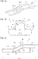
- This embodiment describes a target pressed component shape 1 after press forming taking, as an example, a case of performing forming into the pressed component shape 1 having a hat-shaped cross section and having curved portions 10 in two places along the longitudinal direction as illustrated in FIG. 1 . More specifically, this embodiment exemplifies, as the target pressed component shape 1, a case of a hat-shaped cross section and having a curved portion 10A where a top sheet portion 1A is curved to be recessed (bent downward) and a curved portion 10B where the top sheet portion 1A is curved to project (bent upward) in two places along the longitudinal direction as illustrated in FIG. 1 .
- the curved portion 10 may be formed in one place or the curved portions 10 may be formed in three or more places. Even when the curved portions 10 are formed in two or more places, a shape may be acceptable in which the curved portions 10 in the two places adjacent to each other are curved in the same direction.
- FIG. 1 is the dimensions in Examples and do not limit the present invention at all.
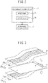
- a method for manufacturing a pressed component of this embodiment includes a preliminary forming step 2 and a component forming step 3 as illustrated in FIG. 2 .
- the preliminary forming step 2 is a step of obtaining a metal sheet for main forming difficult to cause wrinkles by applying preliminary forming before main forming to the metal sheet.
- the preliminary forming step 2 has a first step 2A of giving, to a flat metal sheet, a curved shape following the curves of the curved portions 10 provided in the pressed component shape 1 along the longitudinal direction of the pressed component shape 1 and a second step 2B of forming first beads 4a and second beads 4b at positions where a first bent portion 1d and a second bent portion 1e are formed, respectively.
- the first beads 4a and the second beads 4b each continuously or partially extend along the longitudinal direction.
- the second step 2B may be a step of forming only either the first beads 4a or the second beads 4b. Further, the first beads 4a and the second beads 4b may be arranged such that the formation positions of the first beads 4a and the formation positions of the second beads 4b do not overlap with each other in the longitudinal direction.
- the preliminary forming step 2 may include only the second step 2B.
- the "beads continuously or partially extending along the longitudinal direction” includes a case where the beads are continuously formed over the entire length in the longitudinal direction of the metal sheet 4 and a case where the beads are formed in a part along the longitudinal direction of the metal sheet 4.
- a plurality of beads may be formed at intervals along the longitudinal direction of the metal sheet 4.
- the beads may be continuously formed in two or more places where the curved portions 10 are formed or the beads may be individually formed for each of the curved portions 10.
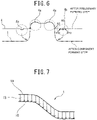
- FIG. 6 illustrates an example of the cross-sectional shapes of the first beads 4a and the second beads 4b.
- the example illustrated in FIG. 6 is an example in which the first beads 4a and the second beads 4b are constituted by a full bead.
- the beads 4a, 4b of this embodiment have a shape in which the cross section of a bent shape extends in a direction intersecting the cross section (longitudinal direction (longitudinal direction of the top sheet portion of the metal sheet 4)).
- the beads 4a, 4b contain a full bead or a half bead having a stepped cross-sectional shape.
- a profile shape in a side view of the top sheet portion 1A of the pressed component shape 1 (for example, profile shape along the longitudinal direction of an edge line portion formed by the first bent portion 1d) is adopted.
- the curvature radius of the curved portions 10 of the curved shape given to the metal sheet 4 in a side view is preferably set to be equal to the curvature radius of the curved portions 10 provided in the pressed component shape 1.
- a difference between the curvature radius of the curved portions 10 of the curved shape given to the metal sheet 4 and the curvature radius of the curved portions 10 provided in the pressed component shape 1 is preferably set to be ⁇ 10% or less of the curvature radius of the curved portions 10 provided in the pressed component shape 1, for example.
- the first bent portion 1d corresponds to the cross section of an edge line portion 1D formed between the top sheet portion 1A and a vertical wall portion.
- the edge line portion 1D is bent to project upward.
- the second bent portion 1e corresponds to the cross section of an edge line portion 1E formed between the vertical wall portion and a flange portion 1C.
- the edge line portion 1E is bent to be recessed upward.
- the second step 2B may have a processing configuration of forming only either the first beads 4a or the second beads 4b.
- the first step 2A and the second step 2B are carried out by pressing using one die.
- the die to be used has forming surfaces 20, 21 of an upper die (die) and a lower die (punch), respectively, given with the same curves as the curved shape of the pressed component shape 1 in a side view.
- the pressed component shape 1 of this embodiment has a shape of having the curved portion 10A in which the top sheet portion 1A is bent to be recessed (bent downward) and the curved portion 10B in which the top sheet portion 1A is bent to project (bent upward).
- the forming surfaces 20, 21 of the upper die (die) and the lower die (punch), respectively, have a surface shape having a portion curved to be recessed (bent downward) and a portion in which the top sheet portion 1A is bent to project (bent upward) according to the shape following the shape in a side view.
- the metal sheet 4 is given with the same curved shape in the width direction (same direction as the width direction of the pressed component shape 1), for example.
- the curved shape in a side view of the forming surfaces 20, 21 of the upper die (die) and the lower die (punch), respectively, is preferably equal to the curved shape in the top sheet portion 1A in a side view in the pressed component shape 1.
- the curved shape of the top sheet portion 1A and the curved shape of the flange portion 1C in a side view along the longitudinal direction are equal or substantially equal to each other. Therefore, the curved shape in a side view of the forming surfaces of the upper die (die) and the lower die (punch) may have a shape following the curved shape of the top sheet portion 1A along the longitudinal direction.
- the curved shapes at the surface position where the top sheet portion 1A is formed and the surface position where the flange portion 1C is formed may have different shapes. In this case, the difference in the curved shape may be absorbed by the forming surfaces forming the vertical wall portion.
- the forming surfaces 20, 21 of the upper die (die) and the lower die (punch) have bead shapes 20a, 21a following the first beads 4a and the bead shapes 20b, 21b following the second beads 4b, respectively, extending along the positions where the first bent portion 1d and the second bent portion 1e are formed, i.e., along the longitudinal direction.
- the positions where the first bead shapes 20a, 21a and the second bead shapes 20b, 21b are formed are positions contactable with a punch shoulder edge line portion and a die shoulder edge line portion of a die in the component forming step 3 in the component forming step 3.
- the first beads 4a preferably have a shape of projecting in the same direction as the projection direction of the first bent portion 1d (a shape of projecting upward in the cross section) (see FIG. 6 ).
- the bead height of the first beads 4a is preferably twice or more the sheet thickness of the metal sheet 4.
- the upper limit of the bead height of the first beads 4a is 20 mm.
- the second beads 4b preferably have a shape of projecting in the same direction as the projection direction of the second bent portion 1e (a shape bent downward) (see FIG. 6 ).
- the bead height of the second beads 4b is preferably twice or more the sheet thickness of the metal sheet 4.
- the upper limit of the bead height of the second beads 4b is 20 mm.
- the metal sheet 4 is press formed using the upper and the lower die above, so that the metal sheet 4 is obtained which includes the first beads 4a and the second beads 4b curved along the longitudinal direction and extending along the longitudinal direction.
- the component forming step 3 is a main forming step of forming the metal sheet 4 processed in the preliminary forming step into the target pressed component shape 1.
- the component forming step 3 includes press forming the metal sheet 4 after the processing in the preliminary forming step 2 using a die having forming surfaces 22, 23 as illustrated in FIG. 4 to obtain a pressed component of the target pressed component shape 1.
- FIG. 4 exemplifies a case where the die has a pad 24 holding the position where the top sheet portion 1A is formed of the metal sheet 4. More specifically, this example exemplifies a case where bending forming is adopted as the press forming. However, the component forming step 3 may adopt stamping in which the top sheet portion 1A is not held by the pad 24.
- the preliminary forming step 2 constitutes at least either the first preliminary forming step or the second preliminary forming step.
- the component forming step 3 constitutes at least either the first component forming step or the second component forming step.
- the preliminary forming step 2 carries out processing of giving the curved shape (shape of being curved in the sheet thickness direction) along the longitudinal direction to the metal sheet 4 and processing of giving at least either the first beads 4a or the second beads 4b to the metal sheet 4 ( FIG. 3 ) as preliminary forming.
- the metal sheet 4 is pressed with the upper die and the lower die for the preliminary forming step 2
- the metal sheet 4 is first transformed into the curved shape along the forming surfaces 20, 21 of the upper die and the lower die, respectively, as the upper die relatively approaches the lower die.
- the upper die relatively approaches the lower die and moves to the bottom dead center, so that the first beads 4a and the second beads 4b are press formed in the metal sheet 4 in the state of the curved sheet shape. More specifically, the formation of the beads 4a, 4b is carried out after the curved shape is given to the metal sheet 4.
- the metal sheet 4 in the preliminary forming step 2 becomes higher in shape rigidity in the longitudinal direction by giving the beads 4a, 4b.
- the metal sheet 4 after the preliminary forming step 2 is pressed in the component forming step 3 to have a U-shaped cross section or a hat-shaped cross section having the curved portions 10 vertically curved in a side view
- the metal sheet 4 has a higher shape rigidity in the longitudinal direction due to the beads 4a, 4b, and therefore the generation of wrinkles due to buckling is suppressed.
- the expansion in the longitudinal direction occurs on the top sheet portion 1A side (projection side) and the contraction in the longitudinal direction occurs on the flange portion 1C side (recess side) in the curved portion 10 projecting toward the top sheet portion 1A side as illustrated in FIG. 5 .
- the contraction in the longitudinal direction occurs on the top sheet portion 1A side (recess side) and the expansion in the longitudinal direction occurs on the flange portion 1C side (projection side).
- the first beads 4a and the second beads 4b as illustrated in FIG. 6 are formed in advance in the metal sheet 4, so that the shape rigidity in the longitudinal direction of the metal sheet 4 increases.
- the generation of wrinkles due to buckling to the metal sheet 4 is suppressed and the deformation of the edge line portion 1D between the top sheet portion 1A and the side wall portion 1B and the edge line portion 1E between the side wall portion 1B and the flange portion 1C is prevented.
- the flange surface is formed by the movement in parallel to the press direction with respect to the top sheet portion 1A as illustrated in FIG. 7 , and the material movement causing wrinkles is suppressed in the press forming in the component forming step 3.
- the flange surface is formed by the movement in parallel to the press direction with respect to the top sheet portion 1A, and the material movement causing wrinkles is further suppressed in the press forming.
- the beads are formed in at least a first estimation region where it is estimated that wrinkles are generated in the top sheet portion 1A when the metal sheet 4 containing a flat sheet is press formed into the pressed component shape 1 and a second estimation region where it is estimated that wrinkles are generated in the flange portion 1C when the metal sheet 4 containing a flat sheet is press formed into the pressed component shape 1.
- first estimation region acquisition unit 6 and a second estimation region acquisition unit 7 as illustrated in FIG. 8 .
- the first estimation region acquisition unit 6 carries out processing of obtaining the first estimation region where it is estimated that wrinkles are generated in the top sheet portion 1A when the metal sheet 4 containing a flat sheet is press formed into the pressed component shape 1.
- the second estimation region acquisition unit 7 carries out processing of obtaining the second estimation region where it is estimated that wrinkles are generated in the flange portion 1C when the metal sheet 4 containing a flat sheet is press formed into the pressed component shape 1.
- the processing by the first estimation region acquisition unit 6 and the second estimation region acquisition unit 7 may be carried out by forming analysis using a computer or may include actually carrying out the press forming.
- the wrinkles in the forming are generated in the curved portion 10 on the side where the material gathers of the curved portions 10, and therefore the curved portion 10 where the top sheet portion 1A is curved to be recessed may be simply estimated as the first estimation region and the curved portion 10 where the top sheet portion 1A is curved to project may be simply estimated as the second estimation region.
- This embodiment exhibits the following effects.
- a 590 MPa class steel sheet (590 material), a 980 MPa class steel sheet (980 material), a 1180 MPa class steel sheet (1180 material), and a 1470 MPa class steel sheet (1470 material) were used as shown in Table 1.
- Table 1 Steel type Sheet thickness (mm) YP (MPa) TS (MPa) EL(%) 590 MPa material 1.6 381 608 29 980 MPa material 1.6 680 1041 16 1180 MPa material 1.6 863 1242 12 1470 MPa material 1.6 1246 1509 8
- a flat sheet with a width W of 240 mm, a length L of 387 mm, and a sheet thickness of 1.0 mmt was used as the metal sheet 4.
- the target component shape of a pressed component was set to a shape having a hat-shaped cross section and the curved portions 10 in two places along the longitudinal direction in a side view as illustrated in FIG. 1 .
- a flat metal sheet was directly press formed into the above-described pressed component shape by forming methods shown in Table 2.
- a metal sheet was press formed into the above-described pressed component shape by forming methods shown in Table 3. More specifically, in the forming methods of Comparative Examples, the metal sheet containing a flat sheet was press formed into the target pressed component shape 1 in the component forming step 3 (main forming step) without the preliminary forming step 2.
- the target pressed component shape was achieved in the component forming step 3 after performing the preliminary forming step 2 based on this embodiment. The results are shown in Tables 2 and 3.
- Table 2 shows the evaluation results (propriety of forming) of the forming methods of Comparative Examples.
- Table 3 shows the evaluation results (propriety of forming) of the forming methods of Examples of Invention.
- the evaluation was performed as follows: “ ⁇ ” when significant wrinkles were generated, “ ⁇ ” when no significant wrinkles were generated but slight wrinkles were formed, and "o” when no wrinkles were generated.
- FIG. 9 illustrates an example of the generation of wrinkles in the top sheet portion 1A and the flange portion 1C in the case of the stamping using the 1180 material in Comparative Examples.
- No. 1 is an example of giving the curved shape and giving the first beads 4a and the second beads 4b containing a full bead to the first bent portion 1d and the second bent portion 1e, respectively.
- the height of the beads 4a, 4b is five times the sheet thickness. The same applies to the other Examples of Invention.
- No. 2 is an example of giving the curved shape, giving the first beads 4a containing a half bead to the first bent portion 1d, and giving the second beads 4b containing a full bead to the second bent portion 1e.
- No. 3 is an example of giving the curved shape, not forming the first beads 4a in the first bent portion 1d, and giving the second beads 4b containing a full bead to the second bent portion 1e.
- No. 4 is an example of giving the curved shape, forming the first beads 4a containing a full bead in the first bent portion 1d, and not forming the second beads 4b in the second bent portion 1e.
- No. 5 is an example of giving the curved shape, giving the first beads 4a containing a half bead to the first bent portion 1d, and giving the second beads 4b containing a half bead to the second bent portion 1e.
- No. 6 is an example of not giving the curved shape, forming the first beads 4a containing a full bead in the first bent portion 1d, and not forming the second beads 4b in the second bent portion 1e.
- No. 7 is an example of giving the curved shape, partially giving the first beads 4a containing a full bead only to the position of the recessed curved portion 10A in the first bent portion 1d, and partially giving the second beads 4b containing a full bead along the longitudinal direction only to the position of the projecting curved portion 10B in the second bent portion 1e.
- the position where the curved portion 10A is formed which is a position for providing the first beads 4a
- the projecting curved portion 10B which is a position for providing the second beads 4b
Landscapes
- Engineering & Computer Science (AREA)
- Mechanical Engineering (AREA)
- Shaping Metal By Deep-Drawing, Or The Like (AREA)
Abstract
Description
- The present invention relates to a technology for manufacturing a pressed component including manufacturing a pressed component having a cross section, such as a U-shaped cross section, a hat-shaped cross section, or an L-shaped cross section, having at least a top sheet portion and a side wall portion continuous to at least one side in the width direction of the top sheet portion and having one or two or more curved portions in which the top sheet portion is curved to project or to be recessed in the sheet thickness direction of the top sheet portion in a side view along the longitudinal direction in the direction intersecting the cross section.
- A large number of pressed components including automobiles and home appliances are produced by transforming a flat metal sheet into various shapes. When mass-producing the pressed components, press forming (pressing) including transforming a metal sheet using a press machine and a die has been widely used for the production of the pressed components. In usual, a metal sheet before work is flat, and therefore the transformation of the metal sheet into a complicated three-dimensional shape requires expansion and contraction of the metal sheet according to a three-dimensional shape. However, the more complicated the shape of the pressed component, the more difficult it is to expand and contract the metal sheet according to the three-dimensional shape. In particular, when the metal sheet to be press formed contains a high-tensile steel sheet or an aluminum alloy sheet having a tensile strength of 590 MPa or more, for example, and a member difficult to form having poor ductility or a poor Lankford Value is adopted as the metal sheet, the above-described problems are likely to occur.
- In the press forming, when the metal sheet cannot be expanded and contracted according to the three-dimensional shape, forming defects, such as cracks or wrinkles, are generated in the metal sheet. More specifically, when the metal sheet is transformed into a three-dimensional shape, the metal sheet has no choice but to expand in a site where the length of the metal sheet is insufficient and the shortage in length is not compensated from the surroundings. Then, when the metal sheet is stretched beyond the ductility of the metal sheet itself, cracks are generated. On the other hand, when the metal sheet is transformed into a three-dimensional shape, wrinkles tend to be generated in a case where the length of the metal sheet needs to be shortened or in a site where the length of the metal sheet excessively flows from the surroundings.
- Examples of a component shape difficult to achieve by press forming include a press formed component having a cross section having a top sheet portion, a vertical wall portion continuous to the top sheet portion, and a flange portion formed continuously to the vertical wall portion and having one or two or more curved shapes in a side view along the longitudinal direction.
- When such a complicated component shape is press formed from a flat metal sheet, tensile deformation or compression deformation occurs in the metal sheet during the forming, and therefore the pressed component is prone to cracks or wrinkles.
- Herein, when a product having the above-described complicated shape is press formed from a metal sheet, bending using a die containing a punch, a die, and a pad or drawing using a die containing a punch, a die, and a blank holder is performed, for example. In the case of the bending, wrinkles are generated in the flange portion, causing forming defects. In the case of the drawing, wrinkles are generated in the top sheet portion, causing forming defects.
- As a countermeasure for the problems, a method for manufacturing a curved component and a device for manufacturing a curved component described in
PTL 1 are mentioned, for example. - PTL 1:
JP 5733475 B - Herein, in the case of the bending, the top sheet portion is restrained by the pad, and therefore the tensile deformation or compression deformation in the top sheet portion can be suppressed. However, the flange portion is not restrained, and therefore the metal sheet tends to have wrinkles under the influence of the tensile deformation or the compression deformation. In the case of the drawing, the flange portion is restrained by the blank holder, and therefore the tensile deformation or the compression deformation in the flange portion can be suppressed. However, the top sheet portion is not restrained, and therefore the metal sheet tends to have wrinkles under the influence of the tensile deformation or the compression deformation. Therefore, the generation of wrinkles cannot be suppressed unless the tensile/compression deformation of the metal sheet occurring in the entire component shape are taken into consideration.
- With respect to a stamping method, neither the top sheet portion nor the flange portion is restrained, and therefore both the top sheet portion and the flange portion tend to have large wrinkles. Therefore, forming by the stamping method is not mainly used, and pressed components having complicated shapes are formed by a bending method, a drawing method, or a composite process thereof.
- Herein, in the method described in
PTL 1, the top sheet portion is restrained by the pad and the flange portion is also restrained by the blank holder, so that the tensile/compression deformation in both the top sheet portion and the flange portion can be suppressed. However, it is necessary to restrain a material with the pad in addition to a normal drawing step, and thus the productivity is poor. Further, the method described inPTL 1 has a high die cost. - The present invention has been made focusing on the above-described points. It is an object of the present invention to suppress the generation of wrinkles by a simple means in press forming into a pressed component shape having one or two or more curved portions in which the top sheet portion is curved to project or to be recessed in a side view.
- The present inventors have studied a press method capable of forming a press formed component without generating cracks or wrinkles and not requiring a complicated die configuration, the press formed component having a hat-shaped cross section including a top sheet portion, vertical wall portions formed on both sides of the top sheet portion, and a flange portion formed continuously to the vertical wall portions and having curved shapes in the upper and lower sides in a side view. Then, the present inventors have obtained the following findings.
- (1) Wrinkles in the flange portion can be suppressed by increasing the shape rigidity of a die shoulder edge line portion in preliminary forming, and then performing forming into a product shape by the bending method in the following step.
- (2) Further, wrinkles in the top sheet portion can also be suppressed in addition to the wrinkles in the flange portion by increasing the shape rigidity of a punch shoulder edge line portion in addition to the die shoulder edge line portion, and then performing forming into a product shape by the bending method in the following step.
- The present invention has been made based on the above-described findings.
- More specifically, to solve the above-described problems, one aspect of the present invention is a method for manufacturing a pressed component including forming a metal sheet into a pressed component shape having: a cross section having a top sheet portion and a side wall portion continuous to at least one side in the width direction of the top sheet portion via a first bent portion; and having one or two or more curved portions in which the top sheet portion is curved to project or to be recessed in a side view along the longitudinal direction in the direction intersecting the cross section, the method which includes: a first preliminary forming step having a step of forming, to the metal sheet, a first bead continuously or partially extending along the longitudinal direction at a position where the first bent portion is formed; and a first component forming step of forming the metal sheet after the first preliminary forming step into the pressed component shape.
- One aspect of the present invention is a method for manufacturing a pressed component including forming a metal sheet into a pressed component shape having: a cross section having a top sheet portion, a side wall portion continuous to at least one side in the width direction of the top sheet portion via a first bent portion, and a flange portion continuous to the side wall portion via a second bent portion; and having one or two or more curved portions in which the top sheet portion is curved to project or to be recessed in a side view along the longitudinal direction in the direction intersecting the cross section, the method which includes: a second preliminary forming step having a step of forming, to the metal sheet, a second bead continuously or partially extending along the longitudinal direction at a position where the second bent portion is formed; and a second component forming step of forming the metal sheet after the second preliminary forming step into the pressed component shape.
- One aspect of the present invention is a metal sheet to be press formed into a pressed component shape having: a cross section having a top sheet portion and a side wall portion continuous to at least one side in the width direction of the top sheet portion via a first bent portion; and having one or two or more curved portions in which the top sheet portion is curved to project or to be recessed in a side view along the longitudinal direction in the direction intersecting the cross section, and the metal sheet has a first bead continuously or partially extending along the longitudinal direction at a position where the first bent portion is formed. One aspect of the present invention is a metal sheet to be press formed into a pressed component shape having: a cross section having a top sheet portion, a side wall portion continuous to at least one side in the width direction of the top sheet portion via a first bent portion, and a flange portion continuous to the side wall portion via a second bent portion; and having one or two or more curved portions in which the top sheet portion is curved to project or to be recessed in a side view along the longitudinal direction in the direction intersecting the cross section, and the metal sheet has a second bead continuously or partially extending along the longitudinal direction at a position where the second bent portion is formed.
- According to the aspects of the present invention, before press forming the metal sheet into the pressed component shape having a curved shape of being vertically curved in a side view, the bead is formed continuously or partially along at least either an edge line portion containing a bent portion connecting the top sheet portion and the side wall portion or an edge line portion containing a bent portion connecting the side wall portion and the flange portion at a position where the edge line portion is formed. As a result, according to the aspects of the present invention, the shape rigidity along the longitudinal direction in the forming into the pressed component shape is improved, and the generation of wrinkles can be effectively suppressed even when the press forming is not necessarily performed while restraining the top sheet portion or the flange portion with the die.
-
-
FIGS. 1A, 1B, and 1C are views illustrating a pressed component shape according to an embodiment based on the present invention, in whichFIG. 1A is a perspective view,FIG. 1B is a side view, andFIG. 1C is an A-A cross-sectional view; -
FIG. 2 is a view illustrating a step example of a method for manufacturing a pressed component according to the embodiment based on the present invention; -
FIG. 3 is a view for explaining forming surfaces of a die in a preliminary forming step; -
FIG. 4 is a view for explaining forming surfaces of a die in a component forming step; -
FIG. 5 is a schematic view viewed from the side for explaining a cause of the generation of wrinkles in a prior art; -
FIG. 6 is a schematic view viewed from the front illustrating an example of beads after a preliminary forming step; -
FIG. 7 is a schematic view viewed from the side for explaining the suppression of wrinkles in the embodiment based on the present invention; -
FIG. 8 is a view for explaining a processing step in a modification according to the embodiment based on the present invention; and -
FIG. 9 is a view illustrating an example of the generation of wrinkles. - Next, embodiments of the present invention will now be described with reference to the drawings.
- The pressed component shape after press forming targeted by this embodiment has a cross-sectional shape, such as a U-shaped cross section, a hat-shaped cross section, or an L-shaped cross section, having at least a top sheet portion and a side wall portion continuous to at least one of both sides in the left and right width direction via a first bent portion. Further, the pressed component shape is a shape having one or two or more curved portions in which the top sheet portion is curved to project or to be recessed in a side view along the longitudinal direction in one place or two or more places in the longitudinal direction in the direction intersecting the cross section (sheet width direction). In the case of the hat-shaped cross section, the pressed component shape is a shape in which a flange portion also follows the curve of the top sheet portion in a side view along the longitudinal direction.
- Herein, this embodiment relates to a technology suitable for manufacturing a pressed component using a metal sheet containing a difficult-to-form member having poor ductility and a poor Lankford Value, such as a high-tensile steel sheet and an aluminum alloy sheet having a tensile strength of 590 MPa or more.
- The description that the top sheet portion is curved to project or to be recessed in a side view refers to a case where the top sheet portion is curved to project or to be recessed in the sheet thickness direction of the top sheet portion along the longitudinal direction.
- This embodiment describes a target pressed
component shape 1 after press forming taking, as an example, a case of performing forming into the pressedcomponent shape 1 having a hat-shaped cross section and havingcurved portions 10 in two places along the longitudinal direction as illustrated inFIG. 1 . More specifically, this embodiment exemplifies, as the target pressedcomponent shape 1, a case of a hat-shaped cross section and having acurved portion 10A where atop sheet portion 1A is curved to be recessed (bent downward) and acurved portion 10B where thetop sheet portion 1A is curved to project (bent upward) in two places along the longitudinal direction as illustrated inFIG. 1 . However, in this embodiment, thecurved portion 10 may be formed in one place or thecurved portions 10 may be formed in three or more places. Even when thecurved portions 10 are formed in two or more places, a shape may be acceptable in which thecurved portions 10 in the two places adjacent to each other are curved in the same direction. - It should be noted that the dimensions illustrated in
FIG. 1 are the dimensions in Examples and do not limit the present invention at all. - A method for manufacturing a pressed component of this embodiment includes a preliminary forming
step 2 and acomponent forming step 3 as illustrated inFIG. 2 . - The preliminary forming
step 2 is a step of obtaining a metal sheet for main forming difficult to cause wrinkles by applying preliminary forming before main forming to the metal sheet. - The preliminary forming
step 2 has afirst step 2A of giving, to a flat metal sheet, a curved shape following the curves of thecurved portions 10 provided in the pressedcomponent shape 1 along the longitudinal direction of the pressedcomponent shape 1 and asecond step 2B of formingfirst beads 4a andsecond beads 4b at positions where a firstbent portion 1d and a secondbent portion 1e are formed, respectively. Thefirst beads 4a and thesecond beads 4b each continuously or partially extend along the longitudinal direction. - The
second step 2B may be a step of forming only either thefirst beads 4a or thesecond beads 4b. Further, thefirst beads 4a and thesecond beads 4b may be arranged such that the formation positions of thefirst beads 4a and the formation positions of thesecond beads 4b do not overlap with each other in the longitudinal direction. - The preliminary forming
step 2 may include only thesecond step 2B. - In this specification, the "beads continuously or partially extending along the longitudinal direction" includes a case where the beads are continuously formed over the entire length in the longitudinal direction of the
metal sheet 4 and a case where the beads are formed in a part along the longitudinal direction of themetal sheet 4. A plurality of beads may be formed at intervals along the longitudinal direction of themetal sheet 4. For example, when the pressedcomponent shape 1 has two or more of thecurved portions 10, the beads may be continuously formed in two or more places where thecurved portions 10 are formed or the beads may be individually formed for each of thecurved portions 10. -
FIG. 6 illustrates an example of the cross-sectional shapes of thefirst beads 4a and thesecond beads 4b. - The example illustrated in
FIG. 6 is an example in which thefirst beads 4a and thesecond beads 4b are constituted by a full bead. - Herein, the
beads beads - For the curved shape following the curves of the
curved portions 10 provided in the pressedcomponent shape 1, a profile shape in a side view of thetop sheet portion 1A of the pressed component shape 1 (for example, profile shape along the longitudinal direction of an edge line portion formed by the firstbent portion 1d) is adopted. The curvature radius of thecurved portions 10 of the curved shape given to themetal sheet 4 in a side view is preferably set to be equal to the curvature radius of thecurved portions 10 provided in the pressedcomponent shape 1. A difference between the curvature radius of thecurved portions 10 of the curved shape given to themetal sheet 4 and the curvature radius of thecurved portions 10 provided in the pressedcomponent shape 1 is preferably set to be ±10% or less of the curvature radius of thecurved portions 10 provided in the pressedcomponent shape 1, for example. - The first
bent portion 1d corresponds to the cross section of anedge line portion 1D formed between thetop sheet portion 1A and a vertical wall portion. Theedge line portion 1D is bent to project upward. The secondbent portion 1e corresponds to the cross section of anedge line portion 1E formed between the vertical wall portion and aflange portion 1C. Theedge line portion 1E is bent to be recessed upward. - Herein, the
second step 2B may have a processing configuration of forming only either thefirst beads 4a or thesecond beads 4b. - In this embodiment, the
first step 2A and thesecond step 2B are carried out by pressing using one die. - As illustrated in
FIG. 3 , the die to be used has formingsurfaces component shape 1 in a side view. The pressedcomponent shape 1 of this embodiment has a shape of having thecurved portion 10A in which thetop sheet portion 1A is bent to be recessed (bent downward) and thecurved portion 10B in which thetop sheet portion 1A is bent to project (bent upward). The forming surfaces 20, 21 of the upper die (die) and the lower die (punch), respectively, have a surface shape having a portion curved to be recessed (bent downward) and a portion in which thetop sheet portion 1A is bent to project (bent upward) according to the shape following the shape in a side view. - Thus, the
metal sheet 4 is given with the same curved shape in the width direction (same direction as the width direction of the pressed component shape 1), for example. - The curved shape in a side view of the forming
surfaces top sheet portion 1A in a side view in the pressedcomponent shape 1. - In usual, the curved shape of the
top sheet portion 1A and the curved shape of theflange portion 1C in a side view along the longitudinal direction are equal or substantially equal to each other. Therefore, the curved shape in a side view of the forming surfaces of the upper die (die) and the lower die (punch) may have a shape following the curved shape of thetop sheet portion 1A along the longitudinal direction. When the curved shape of thetop sheet portion 1A and the curved shape of theflange portion 1C in a side view are different from each other, the curved shapes at the surface position where thetop sheet portion 1A is formed and the surface position where theflange portion 1C is formed may have different shapes. In this case, the difference in the curved shape may be absorbed by the forming surfaces forming the vertical wall portion. - Further, the forming
surfaces bead shapes first beads 4a and the bead shapes 20b, 21b following thesecond beads 4b, respectively, extending along the positions where the firstbent portion 1d and the secondbent portion 1e are formed, i.e., along the longitudinal direction. The positions where thefirst bead shapes component forming step 3 in thecomponent forming step 3. - Herein, the
first beads 4a preferably have a shape of projecting in the same direction as the projection direction of the firstbent portion 1d (a shape of projecting upward in the cross section) (seeFIG. 6 ). - The bead height of the
first beads 4a is preferably twice or more the sheet thickness of themetal sheet 4. The upper limit of the bead height of thefirst beads 4a is 20 mm. - The
second beads 4b preferably have a shape of projecting in the same direction as the projection direction of the secondbent portion 1e (a shape bent downward) (seeFIG. 6 ). - The bead height of the
second beads 4b is preferably twice or more the sheet thickness of themetal sheet 4. The upper limit of the bead height of thesecond beads 4b is 20 mm. - In the preliminary forming
step 2, themetal sheet 4 is press formed using the upper and the lower die above, so that themetal sheet 4 is obtained which includes thefirst beads 4a and thesecond beads 4b curved along the longitudinal direction and extending along the longitudinal direction. - The
component forming step 3 is a main forming step of forming themetal sheet 4 processed in the preliminary forming step into the target pressedcomponent shape 1. - The
component forming step 3 includes press forming themetal sheet 4 after the processing in the preliminary formingstep 2 using a die having formingsurfaces FIG. 4 to obtain a pressed component of the target pressedcomponent shape 1. -
FIG. 4 exemplifies a case where the die has apad 24 holding the position where thetop sheet portion 1A is formed of themetal sheet 4. More specifically, this example exemplifies a case where bending forming is adopted as the press forming. However, thecomponent forming step 3 may adopt stamping in which thetop sheet portion 1A is not held by thepad 24. - Herein, the preliminary forming
step 2 constitutes at least either the first preliminary forming step or the second preliminary forming step. Thecomponent forming step 3 constitutes at least either the first component forming step or the second component forming step. - In this embodiment, the preliminary forming
step 2 carries out processing of giving the curved shape (shape of being curved in the sheet thickness direction) along the longitudinal direction to themetal sheet 4 and processing of giving at least either thefirst beads 4a or thesecond beads 4b to the metal sheet 4 (FIG. 3 ) as preliminary forming. - At this time, when the
metal sheet 4 is pressed with the upper die and the lower die for the preliminary formingstep 2, themetal sheet 4 is first transformed into the curved shape along the formingsurfaces first beads 4a and thesecond beads 4b are press formed in themetal sheet 4 in the state of the curved sheet shape. More specifically, the formation of thebeads metal sheet 4. - By the formation of the
first beads 4a and thesecond beads 4b extending in the longitudinal direction after the curved shape is given, springback along the longitudinal direction during die release of the curved shape given as thefirst step 2A is kept small. - The
metal sheet 4 in the preliminary formingstep 2 becomes higher in shape rigidity in the longitudinal direction by giving thebeads - Next, when the
metal sheet 4 after the preliminary formingstep 2 is pressed in thecomponent forming step 3 to have a U-shaped cross section or a hat-shaped cross section having thecurved portions 10 vertically curved in a side view, themetal sheet 4 has a higher shape rigidity in the longitudinal direction due to thebeads - Herein, when the
metal sheet 4 containing a flat sheet is press formed into the component shape having thecurved portions 10 vertically curved in a side view, the expansion in the longitudinal direction occurs on thetop sheet portion 1A side (projection side) and the contraction in the longitudinal direction occurs on theflange portion 1C side (recess side) in thecurved portion 10 projecting toward thetop sheet portion 1A side as illustrated inFIG. 5 . In thecurved portion 10 recessed toward thetop sheet portion 1A side, the contraction in the longitudinal direction occurs on thetop sheet portion 1A side (recess side) and the expansion in the longitudinal direction occurs on theflange portion 1C side (projection side). - Then, a material movement occurs in the longitudinal direction on the
top sheet portion 1A side and theflange portion 1C side with the expansion and contraction, causing the generation of wrinkles. For example, when the bending forming in which thetop sheet portion 1A is restrained is adopted, there is a risk of the generation of wrinkles due to buckling in thecurved portion 10 projecting toward thetop sheet portion 1A in theflange portion 1C where the material freely moves. When the drawing is adopted, theflange portion 1C is restrained, and therefore there is a risk of the generation of wrinkles due to buckling in thecurved portion 10 in which thetop sheet portion 1A side is a recessed portion in thetop sheet portion 1A where the material freely moves. When the stamping is adopted, the material freely moves in both thetop sheet portion 1A and theflange portion 1C, and therefore there is a risk of the generation of wrinkles in thetop sheet portion 1A and theflange portion 1C. - In contrast thereto, in the
component forming step 3 of this embodiment, thefirst beads 4a and thesecond beads 4b as illustrated inFIG. 6 are formed in advance in themetal sheet 4, so that the shape rigidity in the longitudinal direction of themetal sheet 4 increases. As a result, in the press forming in thecomponent forming step 3, the generation of wrinkles due to buckling to themetal sheet 4 is suppressed and the deformation of theedge line portion 1D between thetop sheet portion 1A and theside wall portion 1B and theedge line portion 1E between theside wall portion 1B and theflange portion 1C is prevented. - Therefore, in this embodiment, the flange surface is formed by the movement in parallel to the press direction with respect to the
top sheet portion 1A as illustrated inFIG. 7 , and the material movement causing wrinkles is suppressed in the press forming in thecomponent forming step 3. - Further, by giving the curved shape along the longitudinal direction to the
metal sheet 4 in advance, the flange surface is formed by the movement in parallel to the press direction with respect to thetop sheet portion 1A, and the material movement causing wrinkles is further suppressed in the press forming. -
- (1) The description above exemplifies the case where the
first step 2A and thesecond step 2B of the preliminary formingstep 2 are carried out with one die.
Thefirst step 2A and thesecond step 2B may be carried out using individual dies for the steps. However, in this case, it is preferable that the curved shape is given to themetal sheet 4 in thefirst step 2A, and then thebeads second step 2B. - (2) The description above exemplifies the case where both the steps of the
first step 2A and thesecond step 2B are carried out in the preliminary formingstep 2. It may acceptable that thefirst step 2A is omitted and only thesecond step 2B (step of forming the beads) is carried out in the preliminary formingstep 2. It may be acceptable that the curved shape of being curved in the vertical direction in a side view and the bending at the firstbent portion 1d and the secondbent portion 1e positions along the width direction are carried out in thecomponent forming step 3. - (3) The description above exemplifies the case where the
first beads 4a and thesecond beads 4b are formed in the entire positions where theedge line portions bent portion 1d and the secondbent portion 1e, respectively, are formed, but thefirst beads 4a and thesecond beads 4b may be partially provided at the corresponding positions of theedge line portions - In this case, it is preferable that the beads are formed in at least a first estimation region where it is estimated that wrinkles are generated in the
top sheet portion 1A when themetal sheet 4 containing a flat sheet is press formed into the pressedcomponent shape 1 and a second estimation region where it is estimated that wrinkles are generated in theflange portion 1C when themetal sheet 4 containing a flat sheet is press formed into the pressedcomponent shape 1. - At this time, it is preferable to include a first estimation
region acquisition unit 6 and a second estimationregion acquisition unit 7 as illustrated inFIG. 8 . - The first estimation
region acquisition unit 6 carries out processing of obtaining the first estimation region where it is estimated that wrinkles are generated in thetop sheet portion 1A when themetal sheet 4 containing a flat sheet is press formed into the pressedcomponent shape 1. - The second estimation
region acquisition unit 7 carries out processing of obtaining the second estimation region where it is estimated that wrinkles are generated in theflange portion 1C when themetal sheet 4 containing a flat sheet is press formed into the pressedcomponent shape 1. - The processing by the first estimation
region acquisition unit 6 and the second estimationregion acquisition unit 7 may be carried out by forming analysis using a computer or may include actually carrying out the press forming. - Further, the wrinkles in the forming are generated in the
curved portion 10 on the side where the material gathers of thecurved portions 10, and therefore thecurved portion 10 where thetop sheet portion 1A is curved to be recessed may be simply estimated as the first estimation region and thecurved portion 10 where thetop sheet portion 1A is curved to project may be simply estimated as the second estimation region. - This embodiment exhibits the following effects.
- (1) In this embodiment, the method for manufacturing a pressed component includes forming the
metal sheet 4 into the pressedcomponent shape 1 having: the cross section having thetop sheet portion 1A and theside wall portion 1B continuous to at least one side in the width direction of thetop sheet portion 1A via the firstbent portion 1d; and having the one or two or morecurved portions 10 in which thetop sheet portion 1A is curved to project or to be recessed in a side view along the longitudinal direction in the direction intersecting the cross section, and the method includes: the first preliminary forming step having the step of forming, to themetal sheet 4, thefirst beads 4a continuously or partially extending along the longitudinal direction at the position where the firstbent portion 1d is formed; and the first component forming step of forming themetal sheet 4 after the first preliminary forming step into the pressedcomponent shape 1.
This configuration can suppress the generation of wrinkles at least in thetop sheet portion 1A by forming thefirst beads 4a along the position where the edge line portion containing a bent portion connecting thetop sheet portion 1A and theside wall portion 1B is formed before performing the press forming into the pressedcomponent shape 1 having the curved shapes in the upper and lower sides in a side view, so that the shape rigidity along the longitudinal direction in the forming into the pressedcomponent shape 1 is improved. - (2) The pressed component shape has the cross section having the flange portion continuous to the side wall portion via the second bent portion, and the first preliminary forming step has the step of forming the first beads and the step of forming, to the metal sheet, the second beads continuously or partially extending along the longitudinal direction at the position where the second bent portion is formed.
According to this configuration, the shape rigidity along the longitudinal direction of not only the edge line portion on thetop sheet portion 1A side but the edge line portion on the flange side is improved, so that the generation of wrinkles not only in thetop sheet portion 1A but in theflange portion 1C can be suppressed. - (3) The first beads and the second beads each partially extend at least at the positions where the curved portions are formed. The position where the curved portion is formed, the position being the formation position of the first beads and the position where the curved portion is formed, the position being the formation position of the second beads, are different from each other.
According to this configuration, the bead formation positions can be suppressed. - (4) The
first beads 4a preferably have a shape of projecting in the same direction as the projection direction of the firstbent portion 1d.
According to this configuration, the bead shape of thefirst beads 4a can be easily crushed in thecomponent forming step 3. The target pressedcomponent shape 1 may be a shape in which the beads are formed along an edge line portion connecting thetop sheet portion 1A and theside wall portion 1B.
Thetop sheet portion 1A is a surface serving as a connection portion with another component, and therefore it is preferable that no beads are formed. - (5) The first preliminary forming step may have the step of giving the curves following the curves of the
curved portions 10 along the longitudinal direction to themetal sheet 4 and the step of forming thefirst beads 4a.
According to this configuration, the first preliminary forming step gives the curved shape together with thefirst beads 4a, so that the shape accuracy in the longitudinal direction is improved, for example. - (6) This embodiment may be configured so that the first estimation
region acquisition unit 6 is included which obtains the first estimation region where it is estimated that wrinkles are generated in thetop sheet portion 1A when themetal sheet 4 containing a flat sheet is press formed into the pressedcomponent shape 1, and the first preliminary forming step partially forms thefirst beads 4a to themetal sheet 4 portion corresponding to the bent portion containing a region serving as the first estimation region of the edge line portion formed by the bent portion.
This configuration prevents the giving of thefirst beads 4a more than necessary. - (7) The bead height of the
first beads 4a is preferably twice or more the sheet thickness of themetal sheet 4.
This configuration can certainly improve the shape rigidity in the longitudinal direction. - (8) This embodiment may be configured so that the second estimation
region acquisition unit 7 is included which obtains the second estimation region where it is estimated that wrinkles are generated in theflange portion 1C when themetal sheet 4 containing a flat sheet is press formed into the pressedcomponent shape 1, and the first preliminary forming step partially forms thesecond beads 4b to themetal sheet 4 portion corresponding to the secondbent portion 1e containing a region serving as the second estimation region of the edge line portion formed by the secondbent portion 1e.
This configuration prevents the giving of thesecond beads 4b more than necessary. - (9) This embodiment may be configured so that the method for manufacturing a pressed component includes forming the
metal sheet 4 into the pressedcomponent shape 1 having: the cross section having thetop sheet portion 1A, theside wall portion 1B continuous to at least one side in the width direction of thetop sheet portion 1A via the firstbent portion 1d, and theflange portion 1C continuous to theside wall portion 1B via the secondbent portion 1e; and having the one or two or morecurved portions 10 in which thetop sheet portion 1A is curved to project or to be recessed in a side view along the longitudinal direction in the direction intersecting the cross section, and the method includes: the second preliminary forming step of forming, to themetal sheet 4, thesecond beads 4b continuously or partially extending along the longitudinal direction at the position where the secondbent portion 1e is formed; and the second component forming step of forming themetal sheet 4 after the second preliminary forming step into the pressedcomponent shape 1.
This configuration can suppress the generation of wrinkles at least in theflange portion 1C by forming thesecond beads 4b at the position where the edge line portion containing the bent portion connecting theside wall portion 1B and thetop sheet portion 1A is formed before performing the press forming into the pressedcomponent shape 1 having the curved shapes in the upper and lower sides in a side view, so that the shape rigidity along the longitudinal direction in the forming into the pressedcomponent shape 1 is improved. - (10) The second preliminary forming step may have the step of giving the curves following the curves of the
curved portions 10 along the longitudinal direction to themetal sheet 4 and the step of forming thesecond beads 4b.
According to this configuration, the second preliminary forming step gives the curved shape together with thesecond beads 4b, and the shape accuracy in the longitudinal direction is improved, for example. - (11) This embodiment may be configured so that the second estimation
region acquisition unit 7 is included which obtains the second estimation region where it is estimated that wrinkles are generated in theflange portion 1C when themetal sheet 4 containing a flat sheet is press formed into the pressedcomponent shape 1, and the second preliminary forming step partially forms thesecond beads 4b to themetal sheet 4 portion corresponding to the secondbent portion 1e containing a region serving as the second estimation region of the edge line portion formed by the secondbent portion 1e.
This configuration prevents the giving of thesecond beads 4b more than necessary. - (12) The
second beads 4b preferably have a shape of being recessed in the same direction as the recessing direction of the secondbent portion 1e.
According to this configuration, the bead shape of thesecond beads 4b can be easily crushed in thecomponent forming step 3. The target pressedcomponent shape 1 may be a shape in which the beads are formed along an edge line portion connecting theside wall portion 1B and theflange portion 1C. - (13) The bead height of the
second beads 4b is preferably twice or more the sheet thickness of themetal sheet 4.
This configuration can certainly improve the shape rigidity in the longitudinal direction. - (14) This embodiment may be configured so that the
metal sheet 4 is to be press formed into the pressedcomponent shape 1 having: the cross section having thetop sheet portion 1A and theside wall portion 1B continuous to at least one side in the width direction of thetop sheet portion 1A via the firstbent portion 1d; and having the one or two or morecurved portions 10 in which thetop sheet portion 1A is curved to project or to be recessed in a side view along the longitudinal direction in the direction intersecting the cross section, and themetal sheet 4 has thefirst beads 4a continuously or partially extending along the longitudinal direction at the position where the firstbent portion 1d is formed.
This configuration can suppress wrinkles generated at least in thetop sheet portion 1A in the press forming into the pressedcomponent shape 1 having: the cross section having thetop sheet portion 1A and theside wall portion 1B continuous to at least one side in the width direction of thetop sheet portion 1A via the firstbent portion 1d; and having the one or two or morecurved portions 10 in which thetop sheet portion 1A is curved to project or to be recessed in a side view along the longitudinal direction in the direction intersecting the cross section. - (15) Further, the
metal sheet 4 may be configured to be press formed into the pressedcomponent shape 1 having the cross section having theflange portion 1C continuous to theside wall portion 1B via the secondbent portion 1e and to have thesecond beads 4b extending along the longitudinal direction at the position where the secondbent portion 1e is formed together with thefirst beads 4a.
This configuration can suppress wrinkles generated in thetop sheet portion 1A and theflange portion 1C in the press forming into the pressedcomponent shape 1 having: the cross section having thetop sheet portion 1A and theside wall portion 1B continuous to at least one side in the width direction of thetop sheet portion 1A via the firstbent portion 1d; and having the one or two or morecurved portions 10 in which thetop sheet portion 1A is curved to project or to be recessed in a side view along the longitudinal direction in the direction intersecting the cross section. - (16) Further, the
metal sheet 4 may be configured to have the curves following the curves of thecurved portions 10 along the longitudinal direction.
This configuration improves the shape accuracy in the longitudinal direction in the press forming into the pressedcomponent shape 1. - (17) This embodiment may be configured so that the
metal sheet 4 is to be press formed into the pressedcomponent shape 1 having: the cross section having thetop sheet portion 1A, theside wall portion 1B continuous to at least one side in the width direction of thetop sheet portion 1A via the firstbent portion 1d, and theflange portion 1C continuous to theside wall portion 1B via the secondbent portion 1e; and having the one or two or morecurved portions 10 in which thetop sheet portion 1A is curved to project or to be recessed in a side view along the longitudinal direction in the direction intersecting the cross section, and themetal sheet 4 has thesecond beads 4b continuously or partially extending along the longitudinal direction at the position where the secondbent portion 1e is formed.
This configuration can suppress wrinkles generated at least in theflange portion 1C in the press forming into the pressedcomponent shape 1 having: the cross section having thetop sheet portion 1A and theside wall portion 1B continuous to at least one side in the width direction of thetop sheet portion 1A via the firstbent portion 1d; and having the one or two or morecurved portions 10 in which thetop sheet portion 1A is curved to project or to be recessed in a side view along the longitudinal direction in the direction intersecting the cross section. - (18) Further, the
metal sheet 4 may be configured to have the curves following the curves of thecurved portions 10 along the longitudinal direction.
This configuration improves the shape accuracy in the longitudinal direction in the press forming into the pressedcomponent shape 1. - Next, examples of the press forming of the above-described embodiment based on the present invention are described. The present invention is not regulated by the following examples described below.
- In this example, a high strength steel sheet of 590 MPa or more was used as the
metal sheet 4. - Specifically, as the
metal sheet 4, a 590 MPa class steel sheet (590 material), a 980 MPa class steel sheet (980 material), a 1180 MPa class steel sheet (1180 material), and a 1470 MPa class steel sheet (1470 material) were used as shown in Table 1.[Table 1] Steel type Sheet thickness (mm) YP (MPa) TS (MPa) EL(%) 590 MPa material 1.6 381 608 29 980 MPa material 1.6 680 1041 16 1180 MPa material 1.6 863 1242 12 1470 MPa material 1.6 1246 1509 8 - As the
metal sheet 4, a flat sheet with a width W of 240 mm, a length L of 387 mm, and a sheet thickness of 1.0 mmt was used. - In this embodiment, the target component shape of a pressed component was set to a shape having a hat-shaped cross section and the
curved portions 10 in two places along the longitudinal direction in a side view as illustrated inFIG. 1 . - In Comparative Examples, a flat metal sheet was directly press formed into the above-described pressed component shape by forming methods shown in Table 2. In Examples of Invention based on the present invention, a metal sheet was press formed into the above-described pressed component shape by forming methods shown in Table 3. More specifically, in the forming methods of Comparative Examples, the metal sheet containing a flat sheet was press formed into the target pressed
component shape 1 in the component forming step 3 (main forming step) without the preliminary formingstep 2. In the forming methods in Examples of Invention based on the present invention, the target pressed component shape was achieved in thecomponent forming step 3 after performing the preliminary formingstep 2 based on this embodiment. The results are shown in Tables 2 and 3. - Table 2 shows the evaluation results (propriety of forming) of the forming methods of Comparative Examples.
- Table 3 shows the evaluation results (propriety of forming) of the forming methods of Examples of Invention.
- In the tables, P pressure is a pad pressure and C pressure is a cushion pressure.
[Table 2] Step P pressure (t) C pressure (t) Determination of wrinkles 590 material 980 material 1180 material 1470 material Recessed portion of top sheet portion Projection portion of flange portion Recessed portion of top sheet portion Projection portion of flange portion Recessed portion of top sheet portion Projection portion of flange portion Recessed portion of top sheet portion Projection portion of flange portion Comparative Examples Form - - × Δ × × × × × × Pad form 20 - ○ Δ ○ × ○ × ○ × Drawing - 50 Δ ○ × ○ × ○ × ○ [Table 3] No. First bead Second bead Step pressure (t) Determination of wrinkles Bead shape Preliminary forming step Component forming step 590 material 980 material 1180 material 1470 material Recessed portion of top sheet portion Projection portion of flange portion Recessed portion of top sheet portion Projection portion of flange portion Recessed portion of top sheet portion Projection portion of flange portion Recessed portion of top sheet portion Projection portion of flange portion 1 2 2 Form Form - ○ ○ ○ ○ ○ ○ ○ ○ 
Form Pad form 20 ○ ○ ○ ○ ○ ○ ○ ○ 2 1 2 Form Form - Δ ○ × ○ × ○ × ○ 
Form Pad form 20 ○ ○ ○ ○ ○ ○ ○ ○ 3 - 2 Form Form - × ○ × ○ × ○ × ○ 
Form Pad form 20 ○ ○ ○ ○ ○ ○ ○ ○ 4 2 - Form Form - ○ Δ ○ × ○ × ○ × 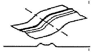
Form Pad form 20 ○ Δ ○ Δ ○ × ○ × 5 2 2 Form Form - ○ Δ ○ × ○ × ○ × 
Form Pad form 20 ○ Δ ○ Δ ○ Δ ○ × 6 2 - Form Form - ○ × ○ × ○ × ○ × 
Form Pad form 20 ○ Δ ○ × ○ × ○ × 7 2 2 Form Form - ○ ○ ○ ○ ○ ○ ○ ○ 
Form Pad form 20 ○ ○ ○ ○ ○ ○ ○ ○ - Herein, the evaluation of press formed products was visually performed and was performed in three grades of "∘", "Δ", and "×". The evaluations are shown in Tables 2 and 3.
- Specifically, the evaluation was performed as follows: "×" when significant wrinkles were generated, "Δ" when no significant wrinkles were generated but slight wrinkles were formed, and "o" when no wrinkles were generated.
- In the forming methods of Comparative Examples, as shown in Table 2, when steel sheets with a tensile strength of 980 MPa or more were used, significant wrinkles were generated in at least either the
top sheet portion 1A or theflange portion 1C. -
FIG. 9 illustrates an example of the generation of wrinkles in thetop sheet portion 1A and theflange portion 1C in the case of the stamping using the 1180 material in Comparative Examples. - On the other hand, it was found in Examples of Invention that the generation of wrinkles was improved in the sites where the
first beads 4a or thesecond beads 4b were given as compared with Comparative Examples as shown in Table 3. - Herein, the shape after the preliminary forming
step 2 in each Example of Invention is described. - No. 1 is an example of giving the curved shape and giving the
first beads 4a and thesecond beads 4b containing a full bead to the firstbent portion 1d and the secondbent portion 1e, respectively. - The height of the
beads - No. 2 is an example of giving the curved shape, giving the
first beads 4a containing a half bead to the firstbent portion 1d, and giving thesecond beads 4b containing a full bead to the secondbent portion 1e. - No. 3 is an example of giving the curved shape, not forming the
first beads 4a in the firstbent portion 1d, and giving thesecond beads 4b containing a full bead to the secondbent portion 1e. - No. 4 is an example of giving the curved shape, forming the
first beads 4a containing a full bead in the firstbent portion 1d, and not forming thesecond beads 4b in the secondbent portion 1e. - No. 5 is an example of giving the curved shape, giving the
first beads 4a containing a half bead to the firstbent portion 1d, and giving thesecond beads 4b containing a half bead to the secondbent portion 1e. - No. 6 is an example of not giving the curved shape, forming the
first beads 4a containing a full bead in the firstbent portion 1d, and not forming thesecond beads 4b in the secondbent portion 1e. - No. 7 is an example of giving the curved shape, partially giving the
first beads 4a containing a full bead only to the position of the recessedcurved portion 10A in the firstbent portion 1d, and partially giving thesecond beads 4b containing a full bead along the longitudinal direction only to the position of the projectingcurved portion 10B in the secondbent portion 1e. In No. 7, the position where thecurved portion 10A is formed, which is a position for providing thefirst beads 4a, and the projectingcurved portion 10B, which is a position for providing thesecond beads 4b, are different from each other in the longitudinal direction. - As is understood from No. 1, when the curved shape was given and the
first beads 4a and thesecond beads 4b each containing a full bead were given to the firstbent portion 1d and the secondbent portion 1e, respectively, no wrinkles were generated in thetop sheet portion 1A and theflange portion 1C. - At this time, even when the
first beads 4a and thesecond beads 4b each containing a full bead were partially given to only a region where the generation of wrinkles was estimated as in No. 7, no wrinkles were generated in thetop sheet portion 1A and theflange portion 1C. - When the
first beads 4a contained a half bead and thesecond beads 4b contained a full bead as in No. 2, no wrinkles were generated in theflange portion 1C but, in the stamping, wrinkles were generated in thetop sheet portion 1A. This is because an improvement of the shape rigidity on thetop sheet portion 1A side was lower than that in No. 1. However, the degree of wrinkles in thetop sheet portion 1A was milder than that in Comparative Examples (Table 2), and, even in the case of the half bead, a wrinkle reduction effect was observed. - It was also found that the generation of wrinkles in the
flange portion 1C was able to be suppressed when only thesecond beads 4b were provided as in No. 3. - It was also found that the generation of wrinkles in the
top sheet portion 1A was able to be suppressed when only thefirst beads 4a were provided as in No. 4. - When the
first beads 4a contained a full bead and thesecond beads 4b contained a half bead as in No. 5, no wrinkles were generated in thetop sheet portion 1A but wrinkles were generated in theflange portion 1C. This is because an improvement of the shape rigidity on theflange portion 1C side was lower than that in No. 1. However, the degree of wrinkles in theflange portion 1C was milder than that in Comparative Examples (Table 2), and, even in the case of the half bead, a wrinkle reduction effect was observed. - Herein, the description is given with reference to a limited number of embodiments, but the scope of the invention is not limited thereto and modifications of each embodiment based on the disclosure above are obvious to those skilled in the art.
- The entire contents of
JP 2020-039600 A (filed March 9, 2020 -
- 1
- pressed component shape
- 1A
- top sheet portion
- 1B
- side wall portion
- 1C
- flange portion
- 1D, 1E
- edge line portion
- 1d
- first bent portion
- 1e
- second bent portion
- 2
- preliminary forming step (first preliminary forming step, second preliminary forming step)
- 2A
- first step
- 2B
- second step
- 3
- component forming step (first component forming step, second component forming step)
- 4
- metal sheet
- 4a
- first bead
- 4b
- second bead
- 6
- first estimation region acquisition unit
- 7
- second estimation region acquisition unit
- 10, 10A, 10B
- curved portion
Claims (16)
- A method for manufacturing a pressed component including forming a metal sheet into a pressed component shape having: a cross section having a top sheet portion and a side wall portion continuous to at least one side in a width direction of the top sheet portion via a first bent portion; and having one or two or more curved portions in which the top sheet portion is curved to project or to be recessed in a side view along a longitudinal direction in a direction intersecting the cross section,
the method comprising:a first preliminary forming step having a step of forming, to the metal sheet, a first bead continuously or partially extending along the longitudinal direction at a position where the first bent portion is formed; anda first component forming step of forming the metal sheet after the first preliminary forming step into the pressed component shape. - The method for manufacturing a pressed component according to claim 1, whereinthe pressed component shape has a cross section having a flange portion continuous to the side wall portion via a second bent portion, andthe first preliminary forming step has a step of forming the first bead and a step of forming, to the metal sheet, a second bead continuously or partially extending along the longitudinal direction at a position where the second bent portion is formed.
- The method for manufacturing a pressed component according to claim 2, whereinthe first bead and the second bead each partially extend at least at positions where the curved portions are formed, andthe position where the curved portion is formed, the position being a formation position of the first bead, and the position where the curved portion is formed, the position being a formation portion of the second bead, are different from each other.
- The method for manufacturing a pressed component according to any one of claims 1 to 3, wherein the first bead has a shape of projecting in a same direction as a projection direction of the first bent portion.
- The method for manufacturing a pressed component according to any one of claims 1 to 4, wherein
the first preliminary forming step has a step of giving curves following curves of the curved portions along the longitudinal direction to the metal sheet. - The method for manufacturing a pressed component according to any one of claims 1 to 5, wherein a bead height of the first bead is twice or more a sheet thickness of the metal sheet.
- A method for manufacturing a pressed component including forming a metal sheet into a pressed component shape having: a cross section having a top sheet portion, a side wall portion continuous to at least one side in a width direction of the top sheet portion via a first bent portion, and a flange portion continuous to the side wall portion via a second bent portion; and having one or two or more curved portions in which the top sheet portion is curved to project or to be recessed in a side view along a longitudinal direction in a direction intersecting the cross section,
the method comprising:a second preliminary forming step having a step of forming, to the metal sheet, a second bead continuously or partially extending along the longitudinal direction at a position where the second bent portion is formed; anda second component forming step of forming the metal sheet after the second preliminary forming step into the pressed component shape. - The method for manufacturing a pressed component according to claim 7, wherein
the second preliminary forming step has:a step of giving curves following curves of the curved portions along the longitudinal direction to the metal sheet; anda step of forming the second bead. - The method for manufacturing a pressed component according to claim 7 or 8, wherein the second bead has a shape of being recessed in a same direction as a recessing direction of the second bent portion.
- The method for manufacturing a pressed component according to any one of claims 7 to 9, wherein a bead height of the second bead is twice or more a sheet thickness of the metal sheet.
- A metal sheet for press forming, the metal sheet being to be press formed into a pressed component shape having: a cross section having a top sheet portion and a side wall portion continuous to at least one side in a width direction of the top sheet portion via a first bent portion; and having one or two or more curved portions in which the top sheet portion is curved to project or to be recessed in a side view along a longitudinal direction in a direction intersecting the cross section,
the metal sheet comprising:
a first bead continuously or partially extending along the longitudinal direction at a position where the first bent portion is formed. - The metal sheet for press forming according to claim 11, the metal sheet being to be press formed into the pressed component shape having a cross section having a flange portion continuous to the side wall portion via a second bent portion,
the metal sheet comprising:
a second bead continuously or partially extending along the longitudinal direction at a position where the second bent portion is formed together with the first bead. - The metal sheet for press forming according to claim 11 or 12, comprising:
curves following curves of the curved portions along the longitudinal direction. - A metal sheet for press forming, the metal sheet being to be press formed into a pressed component shape having: a cross section having a top sheet portion, a side wall portion continuous to at least one side in a width direction of the top sheet portion via a first bent portion, and a flange portion continuous to the side wall portion via a second bent portion; and having one or two or more curved portions in which the top sheet portion is curved to project or to be recessed in a side view along the longitudinal direction in a direction intersecting the cross section,
the metal sheet comprising:
a second bead continuously or partially extending along the longitudinal direction at a position where the second bent portion is formed. - The metal sheet for press forming according to claim 14 comprising:
curves following curves of the curved portions along the longitudinal direction. - A high-tensile steel sheet, having a tensile strength of 590 MPa or more,
the high-tensile steel sheet being used for the method for manufacturing a pressed component according to any one of claims 1 to 10.
Applications Claiming Priority (2)
| Application Number | Priority Date | Filing Date | Title |
|---|---|---|---|
| JP2020039600 | 2020-03-09 | ||
| PCT/JP2021/004801 WO2021181982A1 (en) | 2020-03-09 | 2021-02-09 | Method for manufacturing pressed component, metal plate for press-molding, and high-tensile steel plate |
Publications (2)
| Publication Number | Publication Date |
|---|---|
| EP4119250A1 true EP4119250A1 (en) | 2023-01-18 |
| EP4119250A4 EP4119250A4 (en) | 2023-08-30 |
Family
ID=77670527
Family Applications (1)
| Application Number | Title | Priority Date | Filing Date |
|---|---|---|---|
| EP21768026.3A Pending EP4119250A4 (en) | 2020-03-09 | 2021-02-09 | Method for manufacturing pressed component, metal plate for press-molding, and high-tensile steel plate |
Country Status (7)
| Country | Link |
|---|---|
| US (1) | US12194523B2 (en) |
| EP (1) | EP4119250A4 (en) |
| JP (1) | JP7126079B2 (en) |
| KR (1) | KR102819617B1 (en) |
| CN (1) | CN115210013B (en) |
| MX (1) | MX2022011192A (en) |
| WO (1) | WO2021181982A1 (en) |
Families Citing this family (6)
| Publication number | Priority date | Publication date | Assignee | Title |
|---|---|---|---|---|
| EP4129514A4 (en) * | 2020-03-31 | 2023-09-27 | JFE Steel Corporation | METHOD FOR PRODUCING A PRESSED COMPONENT, METHOD FOR PRODUCING A BLANK MATERIAL AND STEEL SHEET |
| JP7396415B1 (en) * | 2022-09-05 | 2023-12-12 | Jfeスチール株式会社 | Manufacturing method of press molded products |
| JP7708725B2 (en) * | 2022-09-20 | 2025-07-15 | フタバ産業株式会社 | Manufacturing method of press-molded products |
| JP7831456B2 (en) * | 2023-01-23 | 2026-03-17 | Jfeスチール株式会社 | Manufacturing method for press-formed products |
| JP7509278B1 (en) | 2023-06-21 | 2024-07-02 | Jfeスチール株式会社 | Press molding method, manufacturing method of press molded product, intermediate molded product, and press molding die |
| JP7842370B1 (en) * | 2025-11-18 | 2026-04-08 | 日本製鉄株式会社 | Manufacturing method for press-formed products |
Family Cites Families (18)
| Publication number | Priority date | Publication date | Assignee | Title |
|---|---|---|---|---|
| JPH0626733B2 (en) * | 1988-06-15 | 1994-04-13 | サイトーバンキン株式会社 | Manufacturing method and manufacturing apparatus for flat roofing sheet material |
| NL1000668C1 (en) * | 1995-02-13 | 1996-08-16 | Sjoerd Meijer | Method for deforming a plate and a suitable plate for this purpose. |
| US6640605B2 (en) | 1999-01-27 | 2003-11-04 | Milgo Industrial, Inc. | Method of bending sheet metal to form three-dimensional structures |
| WO2006133704A1 (en) * | 2005-06-13 | 2006-12-21 | Isic A/S | Process for creating an angle connection in a plane member |
| US20070123113A1 (en) * | 2005-09-23 | 2007-05-31 | Industrial Origami, Inc. | Method for Forming Angles and Closures in Sheet Material and Sheet Therefor |
| JP5888048B2 (en) * | 2011-06-08 | 2016-03-16 | Jfeスチール株式会社 | Manufacturing method of metal parts with solid edges |
| JP5733475B2 (en) | 2012-09-12 | 2015-06-10 | 新日鐵住金株式会社 | Method for manufacturing curved part and apparatus for manufacturing curved part |
| JP5664810B1 (en) * | 2013-06-27 | 2015-02-04 | Jfeスチール株式会社 | Press forming method and apparatus |
| US10639695B2 (en) | 2014-01-28 | 2020-05-05 | Jfe Steel Corporation | Press forming method, method for manufacturing press-formed component and method for determining preform shape used in these methods |
| WO2016136612A1 (en) | 2015-02-27 | 2016-09-01 | 株式会社 三五 | Press forming method |
| WO2016157976A1 (en) * | 2015-03-31 | 2016-10-06 | Jfeスチール株式会社 | Press molding method, method for manufacturing component in which said press molding method is used, and component manufactured using said press molding method |
| DE102016125671A1 (en) | 2016-12-23 | 2018-06-28 | Thyssenkrupp Ag | Method and device for producing sheet metal components |
| EP3636362B1 (en) * | 2017-06-07 | 2024-11-27 | Nippon Steel Corporation | Press-molded article manufacturing method and press line |
| JP6665837B2 (en) | 2017-07-28 | 2020-03-13 | Jfeスチール株式会社 | Manufacturing method of press-formed product |
| MX2020008962A (en) * | 2018-02-28 | 2020-10-05 | Jfe Steel Corp | PRODUCTION METHOD FOR PRESSED COMPONENTS, PRESS-MOLDED DEVICE, AND PRESS-MOLDED SHEET METAL. |
| JP6631759B1 (en) * | 2018-02-28 | 2020-01-15 | Jfeスチール株式会社 | Press part manufacturing method, press forming apparatus, and metal plate for press forming |
| JP7168203B2 (en) | 2018-09-11 | 2022-11-09 | 日本電気株式会社 | holder |
| JP7144338B2 (en) | 2019-02-05 | 2022-09-29 | フタバ産業株式会社 | Pressing method |
-
2021
- 2021-02-09 US US17/909,883 patent/US12194523B2/en active Active
- 2021-02-09 CN CN202180018792.3A patent/CN115210013B/en active Active
- 2021-02-09 EP EP21768026.3A patent/EP4119250A4/en active Pending
- 2021-02-09 KR KR1020227030609A patent/KR102819617B1/en active Active
- 2021-02-09 JP JP2021558581A patent/JP7126079B2/en active Active
- 2021-02-09 MX MX2022011192A patent/MX2022011192A/en unknown
- 2021-02-09 WO PCT/JP2021/004801 patent/WO2021181982A1/en not_active Ceased
Also Published As
| Publication number | Publication date |
|---|---|
| WO2021181982A1 (en) | 2021-09-16 |
| JPWO2021181982A1 (en) | 2021-09-16 |
| CN115210013A (en) | 2022-10-18 |
| US12194523B2 (en) | 2025-01-14 |
| JP7126079B2 (en) | 2022-08-26 |
| MX2022011192A (en) | 2022-11-08 |
| CN115210013B (en) | 2026-03-31 |
| KR20220134017A (en) | 2022-10-05 |
| US20230120234A1 (en) | 2023-04-20 |
| KR102819617B1 (en) | 2025-06-12 |
| EP4119250A4 (en) | 2023-08-30 |
Similar Documents
| Publication | Publication Date | Title |
|---|---|---|
| EP4119250A1 (en) | Method for manufacturing pressed component, metal plate for press-molding, and high-tensile steel plate | |
| EP2896467B1 (en) | Method for producing curved article | |
| RU2535414C2 (en) | Method of forming l-shape component (versions) | |
| US10596613B2 (en) | Producing method, producing apparatus and producing equipment line of press formed product | |
| EP3524367B1 (en) | Method and device for manufacturing press formed article | |
| CN107186034B (en) | Manufacturing equipment for press-molded products | |
| US11020785B2 (en) | Method and apparatus for manufacturing press component | |
| EP3272438B1 (en) | Method for producing press-molded product, press-molded product, and pressing device | |
| CN111727089B (en) | Method for manufacturing press-molded member, press-molding device, and metal plate for press-molding | |
| EP2962778B1 (en) | Press forming method | |
| CN107708884B (en) | Manufacturing method of stretch flange forming part | |
| CN105813773A (en) | Steel plate material, method for producing same and device for producing same, and method for producing press molded article using said steel plate material | |
| CN107148320A (en) | The manufacture method and manufacture device of compressing product | |
| CN107921504B (en) | Method for manufacturing stretch flange formed part | |
| EP3895824B1 (en) | Press forming method | |
| EP4556134A1 (en) | Method for manufacturing press-molded article | |
| US12030100B1 (en) | Press forming method | |
| JP7283439B2 (en) | METHOD FOR MANUFACTURING PRESS PARTS, AND METAL PLATE | |
| JP6319382B2 (en) | Manufacturing method of stretch flange molded parts | |
| EP4644014A1 (en) | Structural member and method for manufacturing same | |
| EP4454777A1 (en) | Press-molding method and press-molded article manufacturing method | |
| JP2017042826A (en) | Manufacturing method of stretch flange molded parts | |
| JP2021169119A (en) | Manufacturing method for pressed part, metal plate for press molding and high-tensile steel plate |
Legal Events
| Date | Code | Title | Description |
|---|---|---|---|
| STAA | Information on the status of an ep patent application or granted ep patent |
Free format text: STATUS: THE INTERNATIONAL PUBLICATION HAS BEEN MADE |
|
| PUAI | Public reference made under article 153(3) epc to a published international application that has entered the european phase |
Free format text: ORIGINAL CODE: 0009012 |
|
| STAA | Information on the status of an ep patent application or granted ep patent |
Free format text: STATUS: REQUEST FOR EXAMINATION WAS MADE |
|
| 17P | Request for examination filed |
Effective date: 20220908 |
|
| AK | Designated contracting states |
Kind code of ref document: A1 Designated state(s): AL AT BE BG CH CY CZ DE DK EE ES FI FR GB GR HR HU IE IS IT LI LT LU LV MC MK MT NL NO PL PT RO RS SE SI SK SM TR |
|
| DAV | Request for validation of the european patent (deleted) | ||
| DAX | Request for extension of the european patent (deleted) | ||
| A4 | Supplementary search report drawn up and despatched |
Effective date: 20230727 |
|
| RIC1 | Information provided on ipc code assigned before grant |
Ipc: B21D 11/08 20060101ALN20230721BHEP Ipc: B21D 17/02 20060101ALI20230721BHEP Ipc: B21D 22/20 20060101ALI20230721BHEP Ipc: B21D 22/26 20060101AFI20230721BHEP |