EP4119065A1 - Implant delivery with modified detachment feature and pull wire engagement - Google Patents
Implant delivery with modified detachment feature and pull wire engagement Download PDFInfo
- Publication number
- EP4119065A1 EP4119065A1 EP22184574.6A EP22184574A EP4119065A1 EP 4119065 A1 EP4119065 A1 EP 4119065A1 EP 22184574 A EP22184574 A EP 22184574A EP 4119065 A1 EP4119065 A1 EP 4119065A1
- Authority
- EP
- European Patent Office
- Prior art keywords
- pull wire
- detachment feature
- distal
- implant
- opening
- Prior art date
- Legal status (The legal status is an assumption and is not a legal conclusion. Google has not performed a legal analysis and makes no representation as to the accuracy of the status listed.)
- Granted
Links
Images





Classifications
-
- A—HUMAN NECESSITIES
- A61—MEDICAL OR VETERINARY SCIENCE; HYGIENE
- A61B—DIAGNOSIS; SURGERY; IDENTIFICATION
- A61B17/00—Surgical instruments, devices or methods
- A61B17/12—Surgical instruments, devices or methods for ligaturing or otherwise compressing tubular parts of the body, e.g. blood vessels or umbilical cord
- A61B17/12022—Occluding by internal devices, e.g. balloons or releasable wires
-
- A—HUMAN NECESSITIES
- A61—MEDICAL OR VETERINARY SCIENCE; HYGIENE
- A61B—DIAGNOSIS; SURGERY; IDENTIFICATION
- A61B17/00—Surgical instruments, devices or methods
- A61B17/12—Surgical instruments, devices or methods for ligaturing or otherwise compressing tubular parts of the body, e.g. blood vessels or umbilical cord
- A61B17/12022—Occluding by internal devices, e.g. balloons or releasable wires
- A61B17/12131—Occluding by internal devices, e.g. balloons or releasable wires characterised by the type of occluding device
- A61B17/1214—Coils or wires
- A61B17/12154—Coils or wires having stretch limiting means
-
- A—HUMAN NECESSITIES
- A61—MEDICAL OR VETERINARY SCIENCE; HYGIENE
- A61B—DIAGNOSIS; SURGERY; IDENTIFICATION
- A61B17/00—Surgical instruments, devices or methods
- A61B17/12—Surgical instruments, devices or methods for ligaturing or otherwise compressing tubular parts of the body, e.g. blood vessels or umbilical cord
- A61B17/12022—Occluding by internal devices, e.g. balloons or releasable wires
- A61B17/12099—Occluding by internal devices, e.g. balloons or releasable wires characterised by the location of the occluder
- A61B17/12109—Occluding by internal devices, e.g. balloons or releasable wires characterised by the location of the occluder in a blood vessel
- A61B17/12113—Occluding by internal devices, e.g. balloons or releasable wires characterised by the location of the occluder in a blood vessel within an aneurysm
-
- A—HUMAN NECESSITIES
- A61—MEDICAL OR VETERINARY SCIENCE; HYGIENE
- A61B—DIAGNOSIS; SURGERY; IDENTIFICATION
- A61B17/00—Surgical instruments, devices or methods
- A61B17/12—Surgical instruments, devices or methods for ligaturing or otherwise compressing tubular parts of the body, e.g. blood vessels or umbilical cord
- A61B17/12022—Occluding by internal devices, e.g. balloons or releasable wires
- A61B17/12131—Occluding by internal devices, e.g. balloons or releasable wires characterised by the type of occluding device
- A61B17/1214—Coils or wires
- A61B17/12145—Coils or wires having a pre-set deployed three-dimensional shape
-
- A—HUMAN NECESSITIES
- A61—MEDICAL OR VETERINARY SCIENCE; HYGIENE
- A61B—DIAGNOSIS; SURGERY; IDENTIFICATION
- A61B17/00—Surgical instruments, devices or methods
- A61B17/12—Surgical instruments, devices or methods for ligaturing or otherwise compressing tubular parts of the body, e.g. blood vessels or umbilical cord
- A61B17/12022—Occluding by internal devices, e.g. balloons or releasable wires
- A61B17/12131—Occluding by internal devices, e.g. balloons or releasable wires characterised by the type of occluding device
- A61B17/12159—Solid plugs; being solid before insertion
-
- A—HUMAN NECESSITIES
- A61—MEDICAL OR VETERINARY SCIENCE; HYGIENE
- A61B—DIAGNOSIS; SURGERY; IDENTIFICATION
- A61B17/00—Surgical instruments, devices or methods
- A61B17/12—Surgical instruments, devices or methods for ligaturing or otherwise compressing tubular parts of the body, e.g. blood vessels or umbilical cord
- A61B17/12022—Occluding by internal devices, e.g. balloons or releasable wires
- A61B17/12131—Occluding by internal devices, e.g. balloons or releasable wires characterised by the type of occluding device
- A61B17/12168—Occluding by internal devices, e.g. balloons or releasable wires characterised by the type of occluding device having a mesh structure
-
- A—HUMAN NECESSITIES
- A61—MEDICAL OR VETERINARY SCIENCE; HYGIENE
- A61M—DEVICES FOR INTRODUCING MEDIA INTO, OR ONTO, THE BODY; DEVICES FOR TRANSDUCING BODY MEDIA OR FOR TAKING MEDIA FROM THE BODY; DEVICES FOR PRODUCING OR ENDING SLEEP OR STUPOR
- A61M25/00—Catheters; Hollow probes
- A61M25/01—Introducing, guiding, advancing, emplacing or holding catheters
- A61M25/0105—Steering means as part of the catheter or advancing means; Markers for positioning
- A61M25/0133—Tip steering devices
- A61M25/0147—Tip steering devices with movable mechanical means, e.g. pull wires
-
- A—HUMAN NECESSITIES
- A61—MEDICAL OR VETERINARY SCIENCE; HYGIENE
- A61B—DIAGNOSIS; SURGERY; IDENTIFICATION
- A61B17/00—Surgical instruments, devices or methods
- A61B17/12—Surgical instruments, devices or methods for ligaturing or otherwise compressing tubular parts of the body, e.g. blood vessels or umbilical cord
- A61B17/12022—Occluding by internal devices, e.g. balloons or releasable wires
- A61B2017/1205—Introduction devices
- A61B2017/12054—Details concerning the detachment of the occluding device from the introduction device
Definitions
- the bridge 28 can be positioned distally from the proximal opening 22. As the loop wire 400 presses into the pull wire 140 at the proximal opening 22 of the detachment feature 18, the pull wire 140 may bend in response.
- the bridge 28 can provide an opposite force to support the pull wire 140 and provide a limit to which the pull wire 140 is able to bend.
- the combination of the flexible distal section of the delivery tube 302 and the flexible proximal section of the implant 10 can further mitigate the effects of delivery tube shifting.
- the detachment feature 18 can be tapered as it extends further within a lumen 13 of the embolic coil 12 to allow the embolic coil 12 to have additional flexibility where the embolic coil 12 surrounds the tapered region.
- the flat profile of the detachment feature 18 and the minimal number of fused windings near the proximal end 15 of the coil 18 can also allow for high flexibility near the proximal end 15 of the embolic coil 12.
Landscapes
- Health & Medical Sciences (AREA)
- Life Sciences & Earth Sciences (AREA)
- Surgery (AREA)
- Engineering & Computer Science (AREA)
- Veterinary Medicine (AREA)
- Public Health (AREA)
- General Health & Medical Sciences (AREA)
- Biomedical Technology (AREA)
- Heart & Thoracic Surgery (AREA)
- Animal Behavior & Ethology (AREA)
- Molecular Biology (AREA)
- Medical Informatics (AREA)
- Nuclear Medicine, Radiotherapy & Molecular Imaging (AREA)
- Vascular Medicine (AREA)
- Reproductive Health (AREA)
- Neurosurgery (AREA)
- Mechanical Engineering (AREA)
- Biophysics (AREA)
- Pulmonology (AREA)
- Anesthesiology (AREA)
- Hematology (AREA)
- Surgical Instruments (AREA)
- Media Introduction/Drainage Providing Device (AREA)
Abstract
Description
- The present invention generally relates to implantable medical devices, and more particularly, to engagement and detachment features that can secure an implantable medical device to a delivery system during delivery of the implant and can release the implantable medical device from the delivery system.
- Aneurysms can be intravascularly treated by delivering a treatment device to the aneurysm to fill the sac of the aneurysm with embolic material and/or block the neck of the aneurysm to inhibit blood flow into the aneurysm. When filling the aneurysm sac, the embolic material can promote blood clotting to create a thrombotic mass within the aneurysm. When treating the aneurysm neck without substantially filling the aneurysm sac, blood flow into the neck of the aneurysm can be inhibited to induce venous stasis in the aneurysm and facilitate natural formation of a thrombotic mass within the aneurysm.
- In some current treatments, multiple embolic coils, and other embolic implants (e.g. braids) are used to either fill the aneurysm sac or treat the entrance of the aneurysm neck. An embolic implant is attached to a tubular delivery member and delivered via a delivery catheter to an aneurysm. During delivery, the embolic implant can be engaged to the delivery member's implant engagement/deployment system (referred to herein equivalently as an "engagement system" or "deployment system"). When the embolic implant is in position, the deployment system can release the implant, the implant can be left implanted, and the delivery member can be retracted. Some treatments utilize a mechanical engagement/deployment system that can be actuated by a physician to release the implant by pulling one or more wires or other elongated members referred to generically herein as a "pull wire".
- Some of the challenges that have been associated with delivering and deploying embolic implants with delivery members having mechanical engagement systems include premature release of the implant during navigation of tortuous anatomy and/or movement of the delivery member. Premature release can be due to push back from densely packed treatment sites.
- There is therefore a need for improved methods, devices, and systems to facilitate implantation of embolic coils and other implants facing similar challenges.
- Example systems, implants, and methods associated with the same are presented herein which generally include an embolic implant, such as an embolic coil or a tubular braid, that includes a detachment feature configured to engage and be released from a delivery member's engagement system (deployment system). The delivery member can include an elongated delivery tube and the engagement system can include a pull wire extending through the delivery tube and a loop wire attached near a distal end of the delivery tube. To secure the implant to the delivery tube, the loop wire can be positioned through an opening of the detachment feature and a distal end of the pull wire can be positioned through an opening of the loop wire. The detachment feature can include a distal extension configured to engage a distal end of the pull wire and inhibit the pull wire from moving distally into the implant. The detachment feature can also include a sleeve to align the pull wire to the distal extension and/or provide a friction force against the pull wire to inhibit longitudinal movement of the distal end of the pull wire.
- An example system can include an elongated delivery tube, an embolic implant, a loop wire, and a pull wire. The elongated delivery tube can be configured to traverse vasculature. The elongated delivery tube extends along a longitudinal axis of the system. The embolic implant includes a detachment feature. The detachment feature can have a distal extension and a proximal opening. The loop wire can be affixed to the delivery tube. The loop wire can extend through the proximal opening of the detachment feature. The pull wire extends through the delivery tube, extends through an opening in the loop wire, and can be inhibited from moving distally by the distal extension of the detachment feature.
- The detachment feature can further include a sleeve into which the pull wire extends. The sleeve can provide a friction force against the pull wire. The sleeve can further include an elastic material positioned on at least a portion of a perimeter of an opening of the sleeve. The elastic material can provide the friction force against the pull wire. The pull wire can extend through the opening of the sleeve. Additionally, or alternative to providing the friction force, the sleeve can be positioned to align the pull wire longitudinally with the distal extension.
- The detachment feature can have a distal portion that includes the distal extension and a proximal portion that includes the proximal opening. The proximal portion can have a proximal width that is greater than a distal width of the distal portion.
- The embolic implant can include an embolic coil. The distal portion of the detachment feature can be positioned within a lumen of the embolic coil. The distal portion can include the distal extension. The proximal portion of the detachment feature can extend proximally from a proximal end of the embolic coil. The proximal portion can include the proximal opening.
- The distal portion of the detachment feature can further include a distal opening. The embolic implant can further include a stretch resistant fiber passing through the distal opening and extending through the lumen of the embolic coil to a distal end of the embolic coil. The stretch resistant fiber can be effective to limit separation of windings of the embolic coil as the embolic coil is under tension.
- The detachment feature can have a first shoulder affixed to the proximal end of the embolic coil and a second shoulder affixed to the proximal end of the embolic coil. The first shoulder can be longitudinally offset in relation to the second shoulder.
- The embolic implant can include a tubular braid.
- The elongated delivery tube can have notches extending proximally from a distal end of the delivery tube. The proximal portion of the detachment feature can be positioned within the notches.
- The proximal opening in the detachment feature can have an atraumatic surface against the loop wire.
- The detachment feature can have a substantially planar first surface and a second surface opposite the first surface. The distal extension can be disposed on the second surface.
- The pull wire can be in compression longitudinally within the delivery tube.
- An example implant can include an embolic tube and a detachment feature. The embolic tube can have a lumen therethrough. The embolic tube can define a longitudinal axis of the implant. The detachment feature can include a distal portion extending within the lumen, a proximal portion extending proximally from a proximal end of the embolic tube, a proximal opening configured to receive a loop wire therethrough, and a sleeve comprising a longitudinal opening configured to receive a pull wire.
- The detachment feature further can further have a distal extension positioned distally of the sleeve and aligned longitudinally with the opening.
- The sleeve can include an elastic material on at least a portion of a perimeter of the opening.
- An example method for delivering an implant having a detachment feature can include one or more of the following steps presented in no particular order, and the method can include additional steps not included here. The distal end of the pull wire can be inhibited from moving distally by pressing a distal end of a pull wire into a distal extension of the detachment feature. An implant delivery system can be delivered through vasculature, the implant delivery system including an elongated delivery tube, the implant, and the pull wire. The pull wire can be pulled proximally, thereby releasing the detachment feature from the delivery tube.
- The method can further include traversing the implant delivery system through tortuous vasculature. The method can further include inhibiting longitudinal movement of the distal end of the pull wire in relation to the detachment feature by a sleeve providing friction force against the pull wire.
- The method can further include aligning the distal end of the pull wire to the distal extension of the detachment feature by a sleeve positioned on the detachment feature and through which the pull wire extends.
- Pulling the pull wire proximally, thereby releasing the detachment feature from the delivery tube can further include pulling the pull wire proximally to exit a loop of a loop wire affixed the delivery tube, thereby causing the loop wire to exit an opening through the detachment feature to disengage the detachment feature from the delivery tube.
- The above and further aspects of this invention are further discussed with reference to the following description in conjunction with the accompanying drawings, in which like numerals indicate like structural elements and features in various figures. The drawings are not necessarily to scale, emphasis instead being placed upon illustrating principles of the invention. The figures depict one or more implementations of the inventive devices, by way of example only, not by way of limitation.
-
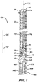
Figure 1 is an illustration of a cut-away view of an implant attached to a delivery member according to aspects of the present invention. -
Figure 2 is an illustration of a side view of a detachment feature according to aspects of the present invention. -
Figures 3A through 3C are illustrations of a sleeve of the detachment feature according to aspects of the present invention. -
Figures 4A and 4B are illustrations of a distal extension of the detachment feature according to aspects of the present invention. -
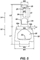
Figure 5 is an illustration of dimensions of the detachment feature of the implant according to aspects of the present invention. -
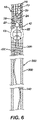
Figure 6 is an illustration of a cut-away view of the implant attached to the delivery member with a pull wire under compression according to aspects of the present invention. -
Figure 7 is an illustration of a system including the implant and delivery member navigating vasculature according to aspects of the present invention. -
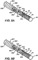
Figure 8A through 8D are a sequence of illustrations depicting detachment of the implant from the delivery member according to aspects of the present invention. -
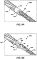
Figures 9A through 9B are illustrations of an alternative implant attached to the delivery system according to aspects of the present invention. -
Figure 10 is a flow diagram of a method of delivering and releasing an example implant according to aspects of the present invention. - As used herein, the terms "about" or "approximately" for any numerical values or ranges indicate a suitable dimensional tolerance that allows the part or collection of components to function for its intended purpose as described herein. More specifically, "about" or "approximately" may refer to the range of values ±20% of the recited value, e.g. "about 90%" may refer to the range of values from 71% to 99%.
- When used herein, the terms "tubular" and "tube" are to be construed broadly and are not limited to a structure that is a right cylinder or strictly circumferential in cross-section or of a uniform cross-section throughout its length. For example, the tubular structure or system is generally illustrated as a substantially right cylindrical structure. However, the tubular system may have a tapered or curved outer surface without departing from the scope of the present invention.
- Systems, implants, and methods are disclosed herein which may be able to attain more precise and repeatable implant detachment. Placement of embolic coils and other implants facing challenges such as partially implanted implants becoming difficult to reposition, shifted delivery systems due to push back during implantation, and/or prematurely released implants may be facilitated. To meet some or all of these needs, example implants can include a detachment feature having a proximal sleeve through which a pull wire can be extended and/or a distal extension which can engage a distal end of the pull wire. The proximal sleeve can be sized, positioned, and otherwise configured to align the pull wire to the distal extension and/or the proximal sleeve can provide a friction force against the pull wire. Preferably, the proximal sleeve provides friction from a disk or tabs that are positioned to press into the pull wire. The disk or tabs can include a biocompatible material(s) that is preferably elastic. The distal extension can provide a hard stop to prevent the distal end of the pull wire from moving further into the implant. The distal extension preferably is shaped in a half-sphere or cone. The sleeve and the distal extension can be respectively formed by milling of the material of the detachment feature and/or attaching material to the detachment feature. Preferably the detachment features can be laser cut from a flat sheet material. The flat sheet material is preferably a radiopaque material that can be welded or otherwise affixed by any suitable means to the embolic coil, braided tube, or other embolic structure of the implant.
-
Figure 1 is an illustration of a cut-away view animplant 10 attached to adelivery member 300. Theimplant 10 includes anembolic coil 12, adetachment feature 18, and a stretchresistant fiber 16. Proximal welds 42 join aproximal end 15 of theembolic coil 12 to thedetachment feature 18. Adistal weld 44 joins adistal end 14 of theembolic coil 12 to the stretchresistant fiber 16. Portions of thecoil 12, welds 42, 44, anddelivery tube 302 are shown in a cut-away view for the purposes of illustration. - The
detachment feature 18 can include adistal opening 24 through which the stretchresistant wire 16 is looped, aproximal opening 22 through which aloop wire 400 extends, asleeve 29 through which apull wire 140 extends, and adistal extension 35 positioned to engage a distal end of thepull wire 140. Thedetachment feature 18 can include abridge 28 positioned between thedistal opening 24 and theproximal opening 22 upon which thesleeve 29 is mounted. Thepull wire 140 can extend through aloop opening 405 of theloop wire 400 to secure thedetachment feature 18 to thedelivery member 300. Theloop wire 400 can extend through a lumen of adelivery tube 302 of thedelivery member 300 and be under tension, thereby compressing a distal section of thedelivery tube 302 having aspiral cut 306. - Example delivery members and engagement/deployment systems are described in
U.S. Patent 10,806,461 U.S. Patent 10,806,462 -
Figure 2 is an illustration of a side view of thedetachment feature 18,loop wire 400, and pullwire 140. Theembolic coil 12 and thedelivery tube 302 are omitted for the sake of the illustration. Thedetachment feature 18 can have a substantially flat profile, which provides flexibility in directions into and out of the page in relation to the orientation illustrated inFigure 1 . Thedetachment feature 18 can have a planarback side 19 and afront side 21 opposite the planar backside 19. Thedistal extension 35 and thesleeve 29 are positioned on thefront side 21. - The
distal extension 35,sleeve 29, and/orbridge 28 can each facilitate in reducing instances of premature deployment. Thedetachment feature 18 can include any combination of these features. - The
bridge 28 can be positioned distally from theproximal opening 22. As theloop wire 400 presses into thepull wire 140 at theproximal opening 22 of thedetachment feature 18, thepull wire 140 may bend in response. Thebridge 28 can provide an opposite force to support thepull wire 140 and provide a limit to which thepull wire 140 is able to bend. - The
sleeve 29 can provide a friction force against thepull wire 140 to inhibit longitudinal movement of thepull wire 140. The sleeve is preferably positioned on thebridge 28; however, the sleeve can alternatively be positioned in aproximal direction 52 in relation to theproximal opening 22 or in adistal direction 54 in relation to thedistal opening 24. When thedetachment feature 18 includes thedistal extension 35 and thesleeve 29, the sleeve can function to align thepull wire 140 to thedistal extension 35, in which case thesleeve 29 may or may not also provide a friction force against thepull wire 140 to inhibit longitudinal movement of thepull wire 140. - The
distal extension 35 is preferably at a distal end of thedetachment feature 18 so that thepull wire 140 can have maximum extension through the loop opening 405 of theloop wire 400 without reducing flexibility of theembolic coil 12. - To facilitate repositioning of the implant, the stretch
resistant fiber 16 can extend through theembolic coil 12 and limit separation of windings of thecoil 12 when thecoil 12 is bent and/or pulled. By limiting the separation of the windings, theembolic coil 12 is less likely to become tangled when partially implanted and less likely to be stretched or otherwise deformed when retracted. Theembolic coil 12 can thereby be more easily repositioned compared to an embolic coil lacking the stretchresistant fiber 16. - To reduce effects of push back during implantation, the
detachment feature 18 can be sized and affixed to theembolic coil 12 to provide anembolic coil implant 10 with a highly flexible proximal section. Anembolic coil implant 10 having a highly flexible proximal section can reduce push back force on thedelivery tube 302 and thereby mitigate the effects of thedelivery tube 302 shifting. Additionally, or alternatively, thedetachment feature 18 can be sized to mate with adelivery tube 302 having a highly flexible distal section, and the highly flexible distal section of the delivery tube can mitigate the effects of the delivery tube shifting. When anembolic coil implant 10 having a highly flexible proximal section is mated to adelivery tube 302 having a highly flexible distal portion, the combination of the flexible distal section of thedelivery tube 302 and the flexible proximal section of theimplant 10 can further mitigate the effects of delivery tube shifting. Although not illustrated, thedetachment feature 18 can be tapered as it extends further within alumen 13 of theembolic coil 12 to allow theembolic coil 12 to have additional flexibility where theembolic coil 12 surrounds the tapered region. The flat profile of thedetachment feature 18 and the minimal number of fused windings near theproximal end 15 of thecoil 18 can also allow for high flexibility near theproximal end 15 of theembolic coil 12. -
Figures 3A through 3C are illustrations of thesleeve 29 of thedetachment feature 18.Figure 3A is a perspective view of afirst example sleeve 29a and thedistal opening 24 of thedetachment feature 18.Figure 3B is a planar view of asleeve opening 46a of thefirst example sleeve 29a. Thefirst example sleeve 29a includestabs 48a extending inwardly from a perimeter of thesleeve opening 46a to converge on apull wire opening 49a.Figure 3C is a perspective view of asecond example sleeve 29b and thedistal opening 24 of thedetachment feature 18. Thesecond example sleeve 29b includes adisk 48b within asleeve opening 46b. Thedisk 48b has apull wire opening 49b at its center. - The
tabs 48a anddisk 48b of thesleeve tabs 48a anddisk 48b of thesleeve -
Figures 4A and 4B are illustrations of thedistal extension 35 of thedetachment feature 18.Figure 4A illustrates a first exampledistal extension 35a having ashallow cavity 37a for receiving the distal end of thepull wire 140.Figure 4B illustrates a second exampledistal extension 35b having adeeper cavity 37b for receiving the distal end of thepull wire 140. Preferably thedistal extension 35 has a semi-conical shape such as illustrated inFigure 4A and 4B . -
Figure 5 is an illustration of dimensions of thedetachment feature 18. Theproximal portion 32 has a first length L1 measured from a proximal end of thedetachment feature 18 to ashoulder 36a of thedetachment feature 18. Thedistal portion 34 has a second length L2 measured from theshoulder 36a to a distal end of thedetachment feature 18. Thedistal opening 24 of thedetachment feature 18 has a third length L3. Thedetachment feature 18 can have afirst shoulder 36a and asecond shoulder 36b opposite thefirst shoulder 36a. Theshoulders proximal end 15 of theembolic coil 12. Theshoulders coil 12. Preferably, the fourth length L4 measures about half of a diameter D1 a winding of the coil 12 (seeFigure 1 ). - The
proximal portion 32 has a first width W1 that is a maximum width of theproximal portion 32, a second width W2 that is a minimum width of a main part of theproximal portion 32, and a third width W3 of a proximal extension 38. The proximal extension 38 is sized to fit within a lumen of thedelivery tube 302, therefore the third width W3 is less than, and preferably approximately equal to, a diameter of the lumen of thedelivery tube 302. Thedistal portion 34 of thedetachment feature 18 has a fourth width W4 that is less than a diameter of thelumen 13 of theembolic coil 12. In some examples, although not illustrated, the width of the distal portion can taper, becoming narrower in thedistal direction 54 of thedetachment feature 18 to improve flexibility of theembolic coil 12 near theproximal end 15 of the coil. Thedistal opening 24 of thedetachment feature 18 can have a fifth width W5. - The
proximal opening 22 can have anatraumatic surface 23 against which theloop wire 400 can press to minimize abrasion to theloop wire 400 by thedetachment feature 18. Thedistal opening 24 can have anatraumatic surface 25 against which the stretchresistant fiber 16 can press to minimize abrasion to the stretchresistant fiber 16 by thedetachment feature 18. -
Figure 6 is an illustration of a cut-away view of theimplant 10 attached to thedelivery member 300 with thepull wire 140 under compression. Because thedistal extension 35 inhibits thepull wire 140 from moving distally into theembolic coil 12, thepull wire 140 can be loaded under compression within thedelivery tube 302. -
Figure 7 is an illustration of asystem 100 including theimplant 10 anddelivery member 300 navigating vasculature through aguide catheter 200. As thesystem 100 navigates bends A, B, C thesystem 100 tends to extend to the extremes of the bends A, B, C. Similarly, as thedelivery tube 302 bends, thepull wire 140 tends to move to extremes of thedelivery tube 302 at the bends A, B, C. Without placing thepull wire 140 under compression as illustration inFigure 6 and without providing a friction force from thesleeve 29 to thepull wire 140, the distal end of thepull wire 140 can move in theproximal direction 52 in relation to theloop wire opening 405 as thesystem 100 navigates the bends A, B, C. In extreme circumstances, the distal end of thepull wire 140 can travel proximally past theloop wire opening 405 to cause premature release of theimplant 10. - As described here, however, by placing the
pull wire 140 under compression as illustrated inFigure 6 , thepull wire 140 has slack to accommodate movement to the extremes of thedelivery tube 302 in the bends. If thedetachment feature 18 includes asleeve 29 that provides frictional force against thepull wire 140, the sleeve can provide tension to thepull wire 140 to prevent thepull wire 140 from moving to the extremes of thedelivery tube 302. These mitigating measures can be used alone or in combination to reduce the likelihood of premature release of theimplant 10. -
Figures 8A through 8D are a sequence of illustrations depicting detachment of theimplant 10 from thedelivery member 300. A portion of thedelivery tube 302 and a portion of theembolic coil 12 are cut away for illustration purposes. -
Figure 8A illustrates the engagement system including thepull wire 140 and theloop wire 400 in a locked configuration on thedetachment feature 18 of theimplant 10. Thedelivery tube 300 includes acompressible portion 306 that can be compressed. Thedetachment feature 18 is secured to thedelivery tube 302 by theloop wire 400 and thepull wire 140 as described in greater detail in relation toFigure 1 . -
Figure 8B illustrates thepull wire 140 being drawn proximally to begin the release sequence for theimplant 10. Thepull wire 140 proximally exits thedistal extension 35 and/or thesleeve 29 of thedetachment feature 18. -
Figure 8C illustrates the instant thepull wire 140 exits theopening 405 of theloop wire 400, allowing thedistal end 404 of theloop wire 400 to fall away and exit thedetachment feature 18. As shown, there is now nothing holding theimplant 10 to thedelivery tube 300. -
Figure 8D illustrates the end of the release sequence. Here, thecompressible portion 306 has expanded/returned to its original shape and "sprung" forward. An elastic force E is imparted by thedistal end 304 of thedelivery tube 300 to theimplant 10 to "push" it away to ensure a clean separation and delivery of theimplant 10. As made visible inFigure 8D , thedelivery tube 302 can include anotch 310 sized and configured to receive theproximal portion 32 of thedetachment feature 18 of theimplant 10, and likewise theproximal portion 32 of thedetachment feature 18 can be sized to fit within thenotch 310 of thedelivery tube 302. -
Figures 9A through 9B are illustrations of analternative system 100a including analternative implant 10a attached to thedelivery member 300. Theimplant 10a includes atubular braid 12a in place of theembolic coil 12. Thedetachment feature 18a lacks thedistal opening 24 and is otherwise similarly configured to thedetachment feature 18 described and illustrated elsewhere herein. Thesystem 100a is configured to deliver theimplant 10a as illustrated in bothFigure 9A and 9B . A portion of thedelivery tube 302 and a portion of thebraid 12a are cut away inFigure 9B for the sake of illustration. -
Figure 10 is a flow diagram of amethod 500 of delivering and releasing an example implant. Themethod 500 can be applied to any of theexample implants - At
step 502, a distal end of a pull wire can be pressed into a distal extension of a detachment feature of an implant, thereby inhibiting the distal end of the pull wire from moving distally. The pull wire, detachment feature, and distal extension can respectively be configured similarly to correspondingcomponents - At step 504, an implant delivery system, including the implant, the pull wire, and an elongated delivery tube, can be delivered through vasculature. The implant delivery system can be configured similarly to the
implant delivery systems delivery tube 300 disclosed herein, variations thereof, and alternatives thereto as understood by a person skilled in the pertinent art. The vasculature through which the delivery system is delivered can be tortuous. As the delivery system is delivered through tortuous vasculature, longitudinal movement of the distal end of the pull wire can be inhibited by a sleeve providing friction force against the pull wire. The sleeve can be configured similarly to theexample sleeve 29 disclosed herein, variations thereof, and alternatives thereto as understood by a person skilled in the pertinent art. The distal end of the pull wire can be aligned to the distal extension by the sleeve. - At
step 506, the pull wire can be pulled proximally to release the detachment feature from the delivery tube. The pull wire can be pulled proximally through a loop of a loop wire affixed to the delivery tube, thereby causing the loop wire to exit an opening of the detachment feature to disengage the detachment feature from the delivery tube. - The descriptions contained herein are examples of embodiments of the invention and are not intended in any way to limit the scope of the invention. As described herein, the invention contemplates many variations and modifications of the implant and methods for making and using the same, including alternative materials (including bioabsorbable materials), alternative geometries of component parts, alternative positioning of component parts in relation to each other, etc. Modifications apparent to those skilled in the pertinent art to which this invention relates and are intended to be within the scope of the claims which follow.
- Aspects of the invention:
- 1. A method of delivering an implant comprising a detachment feature, the method comprising:
- inhibiting a distal end of a pull wire from moving distally by pressing the distal end of the pull wire into a distal extension of the detachment feature;
- deliver an implant delivery system through vasculature, the implant delivery system comprising an elongated delivery tube, the implant, and the pull wire; and
- pulling the pull wire proximally, thereby releasing the detachment feature from the delivery tube.
- 2. The method of Aspect 1, further comprising:
- traversing the implant delivery system through tortuous vasculature; and
- inhibiting longitudinal movement of the distal end of the pull wire in relation to the detachment feature by a sleeve providing friction force against the pull wire.
- 3. The method of Aspect 1, further comprising:
aligning the distal end of the pull wire to the distal extension of the detachment feature by a sleeve positioned on the detachment feature and through which the pull wire extends. - 4. The method of Aspect 1, wherein pulling the pull wire proximally, thereby releasing the detachment feature from the delivery tube further comprises pulling the pull wire proximally to exit a loop of a loop wire affixed the delivery tube, thereby causing the loop wire to exit an opening through the detachment feature to disengage the detachment feature from the delivery tube.
Claims (16)
- A system comprising:an elongated delivery tube configured to traverse vasculature and extending along a longitudinal axis of the system;an embolic implant comprising a detachment feature comprising, the detachment feature comprising a distal extension and a proximal opening;a loop wire affixed to the delivery tube and extending through the proximal opening of the detachment feature; anda pull wire extending through the delivery tube, extending through an opening in the loop wire, and inhibited from moving distally by the distal extension of the detachment feature.
- The system of Claim 1,wherein the detachment feature further comprises a sleeve into which the pull wire extends, andwherein the sleeve provides a friction force against the pull wire.
- The system of Claim 2,wherein the sleeve comprises an elastic material positioned on at least a portion of a perimeter of an opening of the sleeve and providing the friction force against the pull wire, andwherein the pull wire extends through the opening of the sleeve.
- The system of Claim 1,wherein the detachment feature further comprises a sleeve through which the pull wire extends, andwherein the sleeve is positioned to align the pull wire longitudinally with the distal extension.
- The system of Claim 1,wherein the detachment feature further comprises a distal portion comprising the distal extension and a proximal portion comprising the proximal opening, andwherein the proximal portion comprises a proximal width that is greater than a distal width of the distal portion.
- The system of Claim 1,wherein the embolic implant comprises an embolic coil,wherein a distal portion of the detachment feature is positioned within a lumen of the embolic coil,wherein the distal portion comprises the distal extension,wherein a proximal portion of the detachment feature extends proximally from a proximal end of the embolic coil, andwherein the proximal portion comprises the proximal opening.
- The system of Claim 6,wherein the distal portion of the detachment feature further comprises a distal opening,wherein the embolic implant further comprises a stretch resistant fiber passing through the distal opening and extending through the lumen of the embolic coil to a distal end of the embolic coil, andwherein the stretch resistant fiber is effective to limit separation of windings of the embolic coil as the embolic coil is under tension.
- The system of Claim 6,wherein the detachment feature comprises a first shoulder affixed to the proximal end of the embolic coil and a second shoulder affixed to the proximal end of the embolic coil, andwherein the first shoulder is longitudinally offset in relation to the second shoulder.
- The system of Claim 1, wherein the embolic implant comprises a tubular braid.
- The system of Claim 1,wherein the elongated delivery tube comprises notches extending proximally from a distal end of the delivery tube, andwherein a proximal portion of the detachment feature is positioned within the notches.
- The system of Claim 1, wherein the proximal opening comprises an atraumatic surface against the loop wire.
- The system of Claim 1,wherein the detachment feature comprises a substantially planar first surface and a second surface opposite the first surface, andwherein the distal extension is disposed on the second surface.
- The system of Claim 1,
wherein the pull wire is in compression longitudinally within the delivery tube. - An implant comprising:an embolic tube comprising a lumen therethrough and defining a longitudinal axis of the implant; anda detachment feature comprising:a distal portion extending within the lumen,a proximal portion extending proximally from a proximal end of the embolic tube,a proximal opening configured to receive a loop wire therethrough, anda sleeve comprising a longitudinal opening configured to receive a pull wire.
- The implant of Claim 14, wherein the detachment feature further comprises a distal extension positioned distally of the sleeve and aligned longitudinally with the opening.
- The implant of Claim 14, wherein the sleeve comprises an elastic material(48a, 48b) on at least a portion of a perimeter of the opening.
Applications Claiming Priority (1)
| Application Number | Priority Date | Filing Date | Title |
|---|---|---|---|
| US17/375,375 US11998213B2 (en) | 2021-07-14 | 2021-07-14 | Implant delivery with modified detachment feature and pull wire engagement |
Publications (3)
| Publication Number | Publication Date |
|---|---|
| EP4119065A1 true EP4119065A1 (en) | 2023-01-18 |
| EP4119065C0 EP4119065C0 (en) | 2025-04-09 |
| EP4119065B1 EP4119065B1 (en) | 2025-04-09 |
Family
ID=82595010
Family Applications (1)
| Application Number | Title | Priority Date | Filing Date |
|---|---|---|---|
| EP22184574.6A Active EP4119065B1 (en) | 2021-07-14 | 2022-07-13 | Implant with modified detachment feature and pull wire engagement |
Country Status (6)
| Country | Link |
|---|---|
| US (1) | US11998213B2 (en) |
| EP (1) | EP4119065B1 (en) |
| JP (1) | JP2023014033A (en) |
| KR (1) | KR20230011878A (en) |
| CN (1) | CN115607216A (en) |
| ES (1) | ES3031575T3 (en) |
Cited By (15)
| Publication number | Priority date | Publication date | Assignee | Title |
|---|---|---|---|---|
| EP4205669A1 (en) * | 2021-12-30 | 2023-07-05 | DePuy Synthes Products, Inc. | Implant detachment systems with a modified pull wire |
| US11826051B2 (en) | 2017-12-21 | 2023-11-28 | DePuy Synthes Products, Inc. | Implantable medical device detachment system with split tube and cylindrical coupling |
| US11844490B2 (en) | 2021-12-30 | 2023-12-19 | DePuy Synthes Products, Inc. | Suture linkage for inhibiting premature embolic implant deployment |
| US11871931B2 (en) | 2014-08-08 | 2024-01-16 | DePuy Synthes Products, Inc. | Embolic coil delivery system with retractable mechanical release mechanism |
| US11937825B2 (en) | 2022-03-02 | 2024-03-26 | DePuy Synthes Products, Inc. | Hook wire for preventing premature embolic implant detachment |
| US11937826B2 (en) | 2022-03-14 | 2024-03-26 | DePuy Synthes Products, Inc. | Proximal link wire for preventing premature implant detachment |
| US11951026B2 (en) | 2020-06-30 | 2024-04-09 | DePuy Synthes Products, Inc. | Implantable medical device detachment system with flexible braid section |
| US12011171B2 (en) | 2022-01-06 | 2024-06-18 | DePuy Synthes Products, Inc. | Systems and methods for inhibiting premature embolic implant deployment |
| US12137915B2 (en) | 2022-03-03 | 2024-11-12 | DePuy Synthes Products, Inc. | Elongating wires for inhibiting premature implant detachment |
| US12402886B2 (en) | 2022-06-23 | 2025-09-02 | DePuy Synthes Products, Inc. | Detachment indicator for implant deployment |
| US12419646B2 (en) | 2019-10-03 | 2025-09-23 | DePuy Synthes Products, Inc. | Medical device delivery member with flexible stretch resistant mechanical release |
| US12419645B2 (en) | 2019-06-18 | 2025-09-23 | DePuy Synthes Products, Inc. | Pull wire detachment for intravascular devices |
| US12453836B2 (en) | 2019-07-03 | 2025-10-28 | DePuy Synthes Products, Inc. | Medical device delivery member with flexible stretch resistant distal portion |
| US12471924B2 (en) | 2022-03-02 | 2025-11-18 | DePuy Synthes Products, Inc. | Flexible feature for embolic implant deployment |
| US12508032B2 (en) | 2021-12-31 | 2025-12-30 | DePuy Synthes Products, Inc. | Medical device delivery systems with twisting loop wires |
Citations (5)
| Publication number | Priority date | Publication date | Assignee | Title |
|---|---|---|---|---|
| US20110092997A1 (en) * | 2009-10-16 | 2011-04-21 | Kang Ho Chang | Micro-coil assembly |
| US20180289375A1 (en) * | 2015-01-20 | 2018-10-11 | Neurogami Medical, Inc. | Packaging for surgical implant |
| US10806461B2 (en) | 2018-04-27 | 2020-10-20 | DePuy Synthes Products, Inc. | Implantable medical device detachment system with split tube |
| US10806462B2 (en) | 2017-12-21 | 2020-10-20 | DePuy Synthes Products, Inc. | Implantable medical device detachment system with split tube and cylindrical coupling |
| EP3760139A2 (en) * | 2019-07-03 | 2021-01-06 | DePuy Synthes Products, Inc. | Medical device delivery member with flexible stretch resistant distal portion |
Family Cites Families (210)
| Publication number | Priority date | Publication date | Assignee | Title |
|---|---|---|---|---|
| US3429408A (en) | 1967-04-25 | 1969-02-25 | Associated Spring Corp | Actuator sleeves for spring clutch |
| US5484409A (en) | 1989-08-25 | 1996-01-16 | Scimed Life Systems, Inc. | Intravascular catheter and method for use thereof |
| US5122136A (en) | 1990-03-13 | 1992-06-16 | The Regents Of The University Of California | Endovascular electrolytically detachable guidewire tip for the electroformation of thrombus in arteries, veins, aneurysms, vascular malformations and arteriovenous fistulas |
| US5108407A (en) | 1990-06-08 | 1992-04-28 | Rush-Presbyterian St. Luke's Medical Center | Method and apparatus for placement of an embolic coil |
| US5636639A (en) | 1992-02-18 | 1997-06-10 | Symbiosis Corporation | Endoscopic multiple sample bioptome with enhanced biting action |
| US5263964A (en) | 1992-05-06 | 1993-11-23 | Coil Partners Ltd. | Coaxial traction detachment apparatus and method |
| US5250071A (en) | 1992-09-22 | 1993-10-05 | Target Therapeutics, Inc. | Detachable embolic coil assembly using interlocking clasps and method of use |
| US5350397A (en) | 1992-11-13 | 1994-09-27 | Target Therapeutics, Inc. | Axially detachable embolic coil assembly |
| US5382259A (en) | 1992-10-26 | 1995-01-17 | Target Therapeutics, Inc. | Vasoocclusion coil with attached tubular woven or braided fibrous covering |
| US5334210A (en) | 1993-04-09 | 1994-08-02 | Cook Incorporated | Vascular occlusion assembly |
| US5925059A (en) | 1993-04-19 | 1999-07-20 | Target Therapeutics, Inc. | Detachable embolic coil assembly |
| US5569221A (en) | 1994-07-07 | 1996-10-29 | Ep Technologies, Inc. | Catheter component bond and method |
| US6273404B1 (en) | 1995-06-05 | 2001-08-14 | Scimed Life Systems, Inc. | Method of making monolithic hub and strain relief |
| US5853418A (en) * | 1995-06-30 | 1998-12-29 | Target Therapeutics, Inc. | Stretch resistant vaso-occlusive coils (II) |
| US6168622B1 (en) | 1996-01-24 | 2001-01-02 | Microvena Corporation | Method and apparatus for occluding aneurysms |
| US5899935A (en) | 1997-08-04 | 1999-05-04 | Schneider (Usa) Inc. | Balloon expandable braided stent with restraint |
| US6203547B1 (en) | 1997-12-19 | 2001-03-20 | Target Therapeutics, Inc. | Vaso-occlusion apparatus having a manipulable mechanical detachment joint and a method for using the apparatus |
| US6113622A (en) | 1998-03-10 | 2000-09-05 | Cordis Corporation | Embolic coil hydraulic deployment system |
| US6835185B2 (en) | 1998-12-21 | 2004-12-28 | Micrus Corporation | Intravascular device deployment mechanism incorporating mechanical detachment |
| US6391037B1 (en) | 2000-03-02 | 2002-05-21 | Prodesco, Inc. | Bag for use in the intravascular treatment of saccular aneurysms |
| US6623504B2 (en) | 2000-12-08 | 2003-09-23 | Scimed Life Systems, Inc. | Balloon catheter with radiopaque distal tip |
| WO2002054943A2 (en) | 2001-01-10 | 2002-07-18 | Cordis Neurovascular, Inc. | Embolic coil introducer system |
| US6454780B1 (en) | 2001-06-21 | 2002-09-24 | Scimed Life Systems, Inc. | Aneurysm neck obstruction device |
| US8252040B2 (en) | 2001-07-20 | 2012-08-28 | Microvention, Inc. | Aneurysm treatment device and method of use |
| US8715312B2 (en) | 2001-07-20 | 2014-05-06 | Microvention, Inc. | Aneurysm treatment device and method of use |
| US20030195553A1 (en) | 2002-04-12 | 2003-10-16 | Scimed Life Systems, Inc. | System and method for retaining vaso-occlusive devices within an aneurysm |
| US7485122B2 (en) | 2002-06-27 | 2009-02-03 | Boston Scientific Scimed, Inc. | Integrated anchor coil in stretch-resistant vaso-occlusive coils |
| US8425549B2 (en) | 2002-07-23 | 2013-04-23 | Reverse Medical Corporation | Systems and methods for removing obstructive matter from body lumens and treating vascular defects |
| US7608058B2 (en) | 2002-07-23 | 2009-10-27 | Micrus Corporation | Stretch resistant therapeutic device |
| US7208003B2 (en) | 2002-09-20 | 2007-04-24 | Cordis Neurovascular, Inc. | Reattachable introducer for a medical device deployment system |
| FR2853521B1 (en) | 2003-04-10 | 2005-12-02 | Claude Mialhe | DEVICE FOR EXPANDING A VESSEL AND INTRODUCING VASCULAR IMPLANT |
| US7371228B2 (en) | 2003-09-19 | 2008-05-13 | Medtronic Vascular, Inc. | Delivery of therapeutics to treat aneurysms |
| US20050149108A1 (en) * | 2003-12-17 | 2005-07-07 | Microvention, Inc. | Implant delivery and detachment system and method |
| US9308382B2 (en) | 2004-06-10 | 2016-04-12 | Medtronic Urinary Solutions, Inc. | Implantable pulse generator systems and methods for providing functional and/or therapeutic stimulation of muscles and/or nerves and/or central nervous system tissue |
| US20060025802A1 (en) | 2004-07-30 | 2006-02-02 | Sowers William W | Embolic coil delivery system with U-shaped fiber release mechanism |
| US9655633B2 (en) | 2004-09-10 | 2017-05-23 | Penumbra, Inc. | System and method for treating ischemic stroke |
| CA2581272A1 (en) | 2004-09-22 | 2006-05-18 | Lee R. Guterman | Cranial aneurysm treatment arrangement |
| US20060089637A1 (en) | 2004-10-14 | 2006-04-27 | Werneth Randell L | Ablation catheter |
| US8562672B2 (en) | 2004-11-19 | 2013-10-22 | Medtronic, Inc. | Apparatus for treatment of cardiac valves and method of its manufacture |
| US8425550B2 (en) | 2004-12-01 | 2013-04-23 | Boston Scientific Scimed, Inc. | Embolic coils |
| US7238423B2 (en) | 2004-12-20 | 2007-07-03 | Kimberly-Clark Worldwide, Inc. | Multicomponent fiber including elastic elements |
| US7371252B2 (en) | 2005-06-02 | 2008-05-13 | Cordis Neurovascular, Inc. | Stretch resistant embolic coil delivery system with mechanical release mechanism |
| US20060276825A1 (en) | 2005-06-02 | 2006-12-07 | Vladimir Mitelberg | Stretch resistant embolic coil delivery system with mechanical release mechanism |
| US7799052B2 (en) | 2005-06-02 | 2010-09-21 | Codman & Shurtleff, Inc. | Stretch resistant embolic coil delivery system with mechanical release mechanism |
| US7811305B2 (en) | 2005-06-02 | 2010-10-12 | Codman & Shurtleff, Inc. | Stretch resistant embolic coil delivery system with spring release mechanism |
| US7367987B2 (en) | 2005-06-02 | 2008-05-06 | Cordis Neurovascular, Inc. | Stretch resistant embolic coil delivery system with mechanical release mechanism |
| US20060276827A1 (en) | 2005-06-02 | 2006-12-07 | Vladimir Mitelberg | Stretch resistant embolic coil delivery system with mechanical release mechanism |
| US20060276830A1 (en) | 2005-06-02 | 2006-12-07 | Keith Balgobin | Stretch resistant embolic coil delivery system with mechanical release mechanism |
| US20060276833A1 (en) | 2005-06-02 | 2006-12-07 | Keith Balgobin | Stretch resistant embolic coil delivery system with spring assisted release mechanism |
| US7819891B2 (en) | 2005-06-02 | 2010-10-26 | Codman & Shurtleff, Inc. | Stretch resistant embolic coil delivery system with spring release mechanism |
| US7371251B2 (en) | 2005-06-02 | 2008-05-13 | Cordis Neurovascular, Inc. | Stretch resistant embolic coil delivery system with mechanical release mechanism |
| US7985238B2 (en) | 2005-06-02 | 2011-07-26 | Codman & Shurtleff, Inc. | Embolic coil delivery system with spring wire release mechanism |
| US7708755B2 (en) | 2005-06-02 | 2010-05-04 | Codman & Shurtleff Inc. | Stretch resistant embolic coil delivery system with combined mechanical and pressure release mechanism |
| US7708754B2 (en) | 2005-06-02 | 2010-05-04 | Codman & Shurtleff, Pc | Stretch resistant embolic coil delivery system with mechanical release mechanism |
| US7377932B2 (en) | 2005-06-02 | 2008-05-27 | Cordis Neurovascular, Inc. | Embolic coil delivery system with mechanical release mechanism |
| US7819892B2 (en) | 2005-06-02 | 2010-10-26 | Codman & Shurtleff, Inc. | Embolic coil delivery system with spring wire release mechanism |
| US9636115B2 (en) | 2005-06-14 | 2017-05-02 | Stryker Corporation | Vaso-occlusive delivery device with kink resistant, flexible distal end |
| EP1895927A4 (en) | 2005-06-20 | 2011-03-09 | Medtronic Ablation Frontiers | Ablation catheter |
| US20070083132A1 (en) | 2005-10-11 | 2007-04-12 | Sharrow James S | Medical device coil |
| US8066036B2 (en) | 2005-11-17 | 2011-11-29 | Microvention, Inc. | Three-dimensional complex coil |
| US7942894B2 (en) | 2006-01-31 | 2011-05-17 | Codman & Shurtleff, Inc. | Embolic device delivery system |
| US9757260B2 (en) | 2006-03-30 | 2017-09-12 | Medtronic Vascular, Inc. | Prosthesis with guide lumen |
| US7553321B2 (en) | 2006-03-31 | 2009-06-30 | Cordis Development Corporation | Chemically based vascular occlusion device deployment |
| US7766933B2 (en) | 2006-03-31 | 2010-08-03 | Codman & Shurtleff, Inc. | Stretch resistant design for embolic coils with stabilization bead |
| US9615832B2 (en) | 2006-04-07 | 2017-04-11 | Penumbra, Inc. | Aneurysm occlusion system and method |
| US8777979B2 (en) | 2006-04-17 | 2014-07-15 | Covidien Lp | System and method for mechanically positioning intravascular implants |
| CA2655026C (en) | 2006-06-15 | 2016-08-02 | Microvention, Inc. | Embolization device constructed from expansible polymer |
| US7934506B2 (en) | 2006-06-21 | 2011-05-03 | Koninklijke Philips Electronics N.V. | System and method for temporary tongue suspension |
| US8366720B2 (en) | 2006-07-31 | 2013-02-05 | Codman & Shurtleff, Inc. | Interventional medical device system having an elongation retarding portion and method of using the same |
| US8062325B2 (en) | 2006-07-31 | 2011-11-22 | Codman & Shurtleff, Inc. | Implantable medical device detachment system and methods of using the same |
| US7901444B2 (en) | 2006-09-29 | 2011-03-08 | Codman & Shurtleff, Inc. | Embolic coil delivery system with mechanical release mechanism |
| AU2007303137B2 (en) | 2006-10-03 | 2014-04-10 | Sinclair Pharmaceuticals Limited | Minimally invasive tissue support |
| WO2008085606A1 (en) * | 2006-11-20 | 2008-07-17 | Boston Scientific Scimed, Inc. | Mechanically detachable vaso-occlusive device |
| WO2008064209A1 (en) | 2006-11-20 | 2008-05-29 | Boston Scientific Scimed, Inc. | Mechanically detachable vaso-occlusive device |
| US20080306503A1 (en) | 2006-11-20 | 2008-12-11 | Boston Scientific Scimed, Inc. | Mechanically detachable vaso-occlusive device |
| WO2008074027A1 (en) | 2006-12-13 | 2008-06-19 | Biomerix Corporation | Aneurysm occlusion devices |
| US8197442B2 (en) | 2007-04-27 | 2012-06-12 | Codman & Shurtleff, Inc. | Interventional medical device system having a slotted section and radiopaque marker and method of making the same |
| AU2008254770A1 (en) | 2007-05-18 | 2008-11-27 | Stryker Corporation | Medical implant detachment systems |
| DE102007038446A1 (en) | 2007-08-14 | 2009-02-19 | pfm Produkte für die Medizin AG | Embolisiereinrichtung |
| US20090099592A1 (en) * | 2007-10-15 | 2009-04-16 | Boston Scientific Scimed, Inc. | Detachable Interlock Systems and Methods of Use |
| WO2009086208A2 (en) | 2007-12-21 | 2009-07-09 | Microvention, Inc. | Hydrogel filaments for biomedical uses |
| US8974518B2 (en) | 2008-03-25 | 2015-03-10 | Medtronic Vascular, Inc. | Eversible branch stent-graft and deployment method |
| WO2009135075A1 (en) | 2008-04-30 | 2009-11-05 | Medtronic, Inc. | Techniques for placing medical leads for electrical stimulation of nerve tissue |
| US20090312748A1 (en) | 2008-06-11 | 2009-12-17 | Johnson Kirk L | Rotational detachment mechanism |
| US8070694B2 (en) | 2008-07-14 | 2011-12-06 | Medtronic Vascular, Inc. | Fiber based medical devices and aspiration catheters |
| US8333796B2 (en) | 2008-07-15 | 2012-12-18 | Penumbra, Inc. | Embolic coil implant system and implantation method |
| US9232992B2 (en) | 2008-07-24 | 2016-01-12 | Aga Medical Corporation | Multi-layered medical device for treating a target site and associated method |
| US8721714B2 (en) | 2008-09-17 | 2014-05-13 | Medtronic Corevalve Llc | Delivery system for deployment of medical devices |
| US20100160944A1 (en) | 2008-12-24 | 2010-06-24 | Boston Scientific Scimed, Inc. | Thermally detachable embolic assemblies |
| JP5608731B2 (en) | 2009-04-15 | 2014-10-15 | マイクロベンション インコーポレイテッド | Implant delivery system |
| US8974488B2 (en) | 2009-04-20 | 2015-03-10 | Achieva Medical Limited | Delivery assembly for occlusion device using mechanical interlocking coupling mechanism |
| US8758423B2 (en) | 2009-06-18 | 2014-06-24 | Graftcraft I Goteborg Ab | Device and method for treating ruptured aneurysms |
| WO2011038017A1 (en) | 2009-09-22 | 2011-03-31 | Penumbra, Inc. | Manual actuation system for deployment of implant |
| CN102188300B (en) | 2010-03-02 | 2014-05-28 | 上海微创医疗器械(集团)有限公司 | Aneurismal surgical device |
| CA2795740C (en) | 2010-04-14 | 2018-03-13 | Microvention, Inc. | Implant delivery device |
| US8764811B2 (en) | 2010-04-20 | 2014-07-01 | Medtronic Vascular, Inc. | Controlled tip release stent graft delivery system and method |
| US8876878B2 (en) | 2010-07-23 | 2014-11-04 | Medtronic, Inc. | Attachment mechanism for stent release |
| US8616040B2 (en) | 2010-09-17 | 2013-12-31 | Medtronic Vascular, Inc. | Method of forming a drug-eluting medical device |
| WO2012088162A1 (en) | 2010-12-20 | 2012-06-28 | Microvention, Inc. | Polymer stents and methods of manufacture |
| US20120283768A1 (en) | 2011-05-05 | 2012-11-08 | Sequent Medical Inc. | Method and apparatus for the treatment of large and giant vascular defects |
| US9486604B2 (en) | 2011-05-12 | 2016-11-08 | Medtronic, Inc. | Packaging and preparation tray for a delivery system |
| JP6026513B2 (en) | 2011-05-13 | 2016-11-16 | スパイレーション インコーポレイテッド ディー ビー エイ オリンパス レスピラトリー アメリカ | Deployment catheter |
| WO2012158668A1 (en) | 2011-05-17 | 2012-11-22 | Stryker Corporation | Method of fabricating an implantable medical device that includes one or more thin film polymer support layers |
| WO2012166467A1 (en) | 2011-05-27 | 2012-12-06 | Stryker Corporation | Assembly for percutaneously inserting an implantable medical device, steering the device to a target location and deploying the device |
| US9750565B2 (en) | 2011-09-30 | 2017-09-05 | Medtronic Advanced Energy Llc | Electrosurgical balloons |
| CA2867181C (en) | 2012-03-16 | 2020-08-11 | Microvention, Inc. | Stent and stent delivery device |
| US9717421B2 (en) | 2012-03-26 | 2017-08-01 | Medtronic, Inc. | Implantable medical device delivery catheter with tether |
| US9833625B2 (en) | 2012-03-26 | 2017-12-05 | Medtronic, Inc. | Implantable medical device delivery with inner and outer sheaths |
| US9155540B2 (en) | 2012-03-30 | 2015-10-13 | DePuy Synthes Products, Inc. | Embolic coil detachment mechanism with heating element and kicker |
| US9242290B2 (en) | 2012-04-03 | 2016-01-26 | Medtronic Vascular, Inc. | Method and apparatus for creating formed elements used to make wound stents |
| US9700399B2 (en) | 2012-04-26 | 2017-07-11 | Medtronic Vascular, Inc. | Stopper to prevent graft material slippage in a closed web stent-graft |
| US9549832B2 (en) | 2012-04-26 | 2017-01-24 | Medtronic Vascular, Inc. | Apparatus and methods for filling a drug eluting medical device via capillary action |
| US9149190B2 (en) | 2012-07-17 | 2015-10-06 | Stryker Corporation | Notification system of deviation from predefined conditions |
| US9770251B2 (en) | 2012-08-13 | 2017-09-26 | Microvention, Inc. | Shaped removal device |
| US20140058435A1 (en) | 2012-08-21 | 2014-02-27 | Donald K. Jones | Implant delivery and release system |
| US9504476B2 (en) | 2012-10-01 | 2016-11-29 | Microvention, Inc. | Catheter markers |
| BR112015008245B1 (en) | 2012-10-15 | 2022-09-27 | Microvention, Inc | POLYMERIC TREATMENT COMPOSITIONS |
| US20140135811A1 (en) | 2012-11-13 | 2014-05-15 | Covidien Lp | Occlusive devices |
| US9539022B2 (en) | 2012-11-28 | 2017-01-10 | Microvention, Inc. | Matter conveyance system |
| WO2014089392A1 (en) | 2012-12-07 | 2014-06-12 | Medtronic, Inc. | Minimally invasive implantable neurostimulation system |
| EP2941296B1 (en) | 2013-01-03 | 2019-05-15 | Donald K. Jones | Detachable coil release system and handle assembly |
| US10342546B2 (en) | 2013-01-14 | 2019-07-09 | Microvention, Inc. | Occlusive device |
| GB2509952B (en) | 2013-01-18 | 2015-01-28 | Cook Medical Technologies Llc | Medical device loading and carrier tool |
| US9539382B2 (en) | 2013-03-12 | 2017-01-10 | Medtronic, Inc. | Stepped catheters with flow restrictors and infusion systems using the same |
| WO2014158790A2 (en) * | 2013-03-14 | 2014-10-02 | Incumedx Inc. | Implants, methods of manufacturing the same, and devices and methods for delivering the implants to a vascular disorder of a patient |
| EP2967572B1 (en) | 2013-03-14 | 2019-04-24 | Stryker Corporation | Vaso-occlusive device delivery system |
| EP3009084B1 (en) | 2013-03-14 | 2017-09-13 | Stryker Corporation | Vaso-occlusive device delivery system |
| US9539011B2 (en) | 2013-03-14 | 2017-01-10 | Stryker Corporation | Vaso-occlusive device delivery system |
| US9398966B2 (en) | 2013-03-15 | 2016-07-26 | Medtronic Vascular, Inc. | Welded stent and stent delivery system |
| JP6636908B2 (en) | 2013-03-15 | 2020-01-29 | テルモ株式会社 | Embolism prevention device |
| US9833252B2 (en) | 2013-03-15 | 2017-12-05 | Microvention, Inc. | Multi-component obstruction removal system and method |
| WO2014174437A1 (en) | 2013-04-22 | 2014-10-30 | Sandvik Intellectual Property Ab | Method for drug loading hydroxyapatite coated implant surfaces |
| US9445928B2 (en) | 2013-05-30 | 2016-09-20 | Medtronic Vascular, Inc. | Delivery system having a single handed deployment handle for a retractable outer sheath |
| US9662120B2 (en) | 2013-08-23 | 2017-05-30 | Cook Medical Technologies Llc | Detachable treatment device delivery system utilizing compression at attachment zone |
| US9675782B2 (en) | 2013-10-10 | 2017-06-13 | Medtronic Vascular, Inc. | Catheter pull wire actuation mechanism |
| US9955978B2 (en) | 2013-10-25 | 2018-05-01 | Medtronic Vascular, Inc. | Tissue compression device with multi-chamber bladder |
| US9833604B2 (en) | 2013-12-20 | 2017-12-05 | Microvention, Inc. | Delivery adapter |
| CA2934555C (en) | 2013-12-20 | 2020-07-07 | Microvention, Inc. | Device delivery system |
| US9566072B2 (en) | 2013-12-27 | 2017-02-14 | Blockade Medical, LLC | Coil system |
| US9788839B2 (en) | 2014-02-14 | 2017-10-17 | Cook Medical Technologies Llc | Stable screw-type detachment mechanism |
| EP3128962B1 (en) | 2014-04-08 | 2018-05-23 | Stryker Corporation | Implant delivery system |
| WO2015167997A1 (en) | 2014-04-30 | 2015-11-05 | Stryker Corporation | Implant delivery system and method of use |
| US9060777B1 (en) | 2014-05-28 | 2015-06-23 | Tw Medical Technologies, Llc | Vaso-occlusive devices and methods of use |
| US9668898B2 (en) | 2014-07-24 | 2017-06-06 | Medtronic Vascular, Inc. | Stent delivery system having dynamic deployment and methods of manufacturing same |
| CN106659505B (en) | 2014-07-25 | 2019-07-02 | 因库麦迪斯有限公司 | Embolic coils with shields |
| US9918718B2 (en) | 2014-08-08 | 2018-03-20 | DePuy Synthes Products, Inc. | Embolic coil delivery system with retractable mechanical release mechanism |
| US9770577B2 (en) | 2014-09-15 | 2017-09-26 | Medtronic Xomed, Inc. | Pressure relief for a catheter balloon device |
| KR20170056666A (en) | 2014-09-17 | 2017-05-23 | 메타랙티브 메디컬, 인크. | Expandable body device and method of use |
| US9579484B2 (en) | 2014-09-19 | 2017-02-28 | Medtronic Vascular, Inc. | Sterile molded dispenser |
| GB2533087B (en) | 2014-12-08 | 2018-08-08 | Cook Medical Technologies Llc | Medical implant detachment mechanism and introducer assembly |
| US10857012B2 (en) | 2015-01-20 | 2020-12-08 | Neurogami Medical, Inc. | Vascular implant |
| US9692557B2 (en) | 2015-02-04 | 2017-06-27 | Stryker European Holdings I, Llc | Apparatus and methods for administering treatment within a bodily duct of a patient |
| US10888331B2 (en) | 2015-02-10 | 2021-01-12 | Boston Scientific Scimed, Inc. | Active release of embolic coils |
| EP3291773B1 (en) | 2015-05-07 | 2026-01-07 | The Medical Research, Infrastructure, And Health Services Fund Of The Tel Aviv Medical Center | Temporary interatrial shunts |
| US9717503B2 (en) | 2015-05-11 | 2017-08-01 | Covidien Lp | Electrolytic detachment for implant delivery systems |
| US10398874B2 (en) | 2015-05-29 | 2019-09-03 | Covidien Lp | Catheter distal tip configuration |
| US10307168B2 (en) | 2015-08-07 | 2019-06-04 | Terumo Corporation | Complex coil and manufacturing techniques |
| US10154905B2 (en) | 2015-08-07 | 2018-12-18 | Medtronic Vascular, Inc. | System and method for deflecting a delivery catheter |
| EP3334354B1 (en) | 2015-08-11 | 2021-03-03 | Terumo Corporation | System for implant delivery |
| EP3349689B1 (en) | 2015-09-18 | 2023-12-27 | Microvention, Inc. | Implant retention, detachment, and delivery system |
| CN108156803B (en) | 2015-09-18 | 2021-05-04 | 泰尔茂株式会社 | Pushable Implant Delivery System |
| JP6816126B2 (en) | 2015-09-18 | 2021-01-20 | マイクロベンション インコーポレイテッドMicrovention, Inc. | Releasable delivery system |
| JP6816127B2 (en) | 2015-09-18 | 2021-01-20 | テルモ株式会社 | Vascular prosthesis |
| CN108024821B (en) | 2015-09-21 | 2020-10-30 | 斯瑞克公司 | embolectomy device |
| ES2788738T3 (en) | 2015-09-21 | 2020-10-22 | Stryker Corp | Embolectomy devices |
| US10172632B2 (en) | 2015-09-22 | 2019-01-08 | Medtronic Vascular, Inc. | Occlusion bypassing apparatus with a re-entry needle and a stabilization tube |
| WO2017062383A1 (en) | 2015-10-07 | 2017-04-13 | Stryker Corporation | Multiple barrel clot removal devices |
| US10327791B2 (en) | 2015-10-07 | 2019-06-25 | Medtronic Vascular, Inc. | Occlusion bypassing apparatus with a re-entry needle and a distal stabilization balloon |
| US10786302B2 (en) | 2015-10-09 | 2020-09-29 | Medtronic, Inc. | Method for closure and ablation of atrial appendage |
| US20190021737A1 (en) | 2015-10-14 | 2019-01-24 | Three Rivers Medical Inc. | Mechanical embolization delivery apparatus and methods |
| US10271873B2 (en) | 2015-10-26 | 2019-04-30 | Medtronic Vascular, Inc. | Sheathless guide catheter assembly |
| US20170147765A1 (en) | 2015-11-19 | 2017-05-25 | Penumbra, Inc. | Systems and methods for treatment of stroke |
| US10631946B2 (en) | 2015-11-30 | 2020-04-28 | Penumbra, Inc. | System for endoscopic intracranial procedures |
| WO2017100472A1 (en) | 2015-12-09 | 2017-06-15 | Medtronic Vascular Inc. | Catheter with a lumen shaped as an identification symbol |
| US10159568B2 (en) | 2015-12-14 | 2018-12-25 | Medtronic, Inc. | Delivery system having retractable wires as a coupling mechanism and a deployment mechanism for a self-expanding prosthesis |
| US10500046B2 (en) | 2015-12-14 | 2019-12-10 | Medtronic, Inc. | Delivery system having retractable wires as a coupling mechanism and a deployment mechanism for a self-expanding prosthesis |
| US10743883B2 (en) | 2015-12-30 | 2020-08-18 | Stryker European Holdings I, Llc | Embolic devices and methods of manufacturing same |
| US20170189033A1 (en) | 2016-01-06 | 2017-07-06 | Microvention, Inc. | Occlusive Embolic Coil |
| US10070950B2 (en) | 2016-02-09 | 2018-09-11 | Medtronic Vascular, Inc. | Endoluminal prosthetic assemblies, and associated systems and methods for percutaneous repair of a vascular tissue defect |
| AU2017217879B9 (en) | 2016-02-10 | 2021-08-19 | Microvention, Inc. | Intravascular treatment site access |
| AU2017218115B2 (en) | 2016-02-10 | 2020-03-05 | Microvention, Inc. | Devices for vascular occlusion |
| US10188500B2 (en) | 2016-02-12 | 2019-01-29 | Medtronic Vascular, Inc. | Stent graft with external scaffolding and method |
| US10485579B2 (en) | 2016-02-25 | 2019-11-26 | Indian Wells Medical, Inc. | Steerable endoluminal punch |
| US20170258476A1 (en) | 2016-03-08 | 2017-09-14 | Terumo Kabushiki Kaisha | Blood vessel treatment method |
| US20170281331A1 (en) | 2016-03-31 | 2017-10-05 | Medtronic Vascular, Inc. | Endoluminal prosthetic devices having fluid-absorbable compositions for repair of a vascular tissue defect |
| EP4112111A1 (en) | 2016-03-31 | 2023-01-04 | Medtronic Vascular Inc. | Expandable introducer sheath |
| US10695542B2 (en) | 2016-04-04 | 2020-06-30 | Medtronic Vascular, Inc. | Drug coated balloon |
| US10252024B2 (en) | 2016-04-05 | 2019-04-09 | Stryker Corporation | Medical devices and methods of manufacturing same |
| US10441407B2 (en) | 2016-04-12 | 2019-10-15 | Medtronic Vascular, Inc. | Gutter filling stent-graft and method |
| US9987122B2 (en) | 2016-04-13 | 2018-06-05 | Medtronic Vascular, Inc. | Iliac branch device and method |
| US10010403B2 (en) | 2016-04-18 | 2018-07-03 | Medtronic Vascular, Inc. | Stent-graft prosthesis and method of manufacture |
| US20170304097A1 (en) | 2016-04-21 | 2017-10-26 | Medtronic Vascular, Inc. | Stent-graft delivery system having an inner shaft component with a loading pad or covering on a distal segment thereof for stent retention |
| US10517711B2 (en) | 2016-04-25 | 2019-12-31 | Medtronic Vascular, Inc. | Dissection prosthesis system and method |
| JP6924256B2 (en) | 2016-04-25 | 2021-08-25 | ストライカー コーポレイションStryker Corporation | Pre-installed reversing tractor thrombectomy device and method |
| JP6934935B2 (en) | 2016-04-25 | 2021-09-15 | ストライカー コーポレイションStryker Corporation | Inverted mechanical thrombectomy and intravascular use |
| ES2859656T3 (en) | 2016-04-25 | 2021-10-04 | Stryker Corp | Anti-jam and macerant thrombectomy appliances |
| US10940294B2 (en) | 2016-04-25 | 2021-03-09 | Medtronic Vascular, Inc. | Balloon catheter including a drug delivery sheath |
| US10406011B2 (en) | 2016-04-28 | 2019-09-10 | Medtronic Vascular, Inc. | Implantable medical device delivery system |
| US10191615B2 (en) | 2016-04-28 | 2019-01-29 | Medtronic Navigation, Inc. | Method and apparatus for image-based navigation |
| US11147952B2 (en) | 2016-04-28 | 2021-10-19 | Medtronic Vascular, Inc. | Drug coated inflatable balloon having a thermal dependent release layer |
| US10292844B2 (en) | 2016-05-17 | 2019-05-21 | Medtronic Vascular, Inc. | Method for compressing a stented prosthesis |
| CN113648518B (en) | 2016-06-01 | 2023-10-20 | 微仙美国有限公司 | Improved reinforced balloon catheter |
| US10285710B2 (en) | 2016-06-01 | 2019-05-14 | DePuy Synthes Products, Inc. | Endovascular detachment system with flexible distal end and heater activated detachment |
| JP6980703B2 (en) | 2016-06-03 | 2021-12-15 | ストライカー コーポレイションStryker Corporation | Inverting thrombectomy device |
| US10646689B2 (en) | 2016-07-29 | 2020-05-12 | Cephea Valve Technologies, Inc. | Mechanical interlock for catheters |
| KR20180047232A (en) | 2016-10-31 | 2018-05-10 | 삼성에스디에스 주식회사 | Method and apparatus for video analysis based on pattern analysis of network packets of real-time video streaming |
| US10258492B2 (en) | 2017-03-03 | 2019-04-16 | Cook Medical Technologies Llc | Prosthesis delivery system with axially collapsible sheath |
| US11305095B2 (en) | 2018-02-22 | 2022-04-19 | Scientia Vascular, Llc | Microfabricated catheter having an intermediate preferred bending section |
| US10631791B2 (en) | 2018-06-25 | 2020-04-28 | Caption Health, Inc. | Video clip selector for medical imaging and diagnosis |
| US11051928B2 (en) | 2019-04-11 | 2021-07-06 | Neuravi Limited | Floating carotid filter |
-
2021
- 2021-07-14 US US17/375,375 patent/US11998213B2/en active Active
-
2022
- 2022-07-11 KR KR1020220084819A patent/KR20230011878A/en active Pending
- 2022-07-13 ES ES22184574T patent/ES3031575T3/en active Active
- 2022-07-13 JP JP2022112279A patent/JP2023014033A/en active Pending
- 2022-07-13 EP EP22184574.6A patent/EP4119065B1/en active Active
- 2022-07-14 CN CN202210823305.7A patent/CN115607216A/en active Pending
Patent Citations (5)
| Publication number | Priority date | Publication date | Assignee | Title |
|---|---|---|---|---|
| US20110092997A1 (en) * | 2009-10-16 | 2011-04-21 | Kang Ho Chang | Micro-coil assembly |
| US20180289375A1 (en) * | 2015-01-20 | 2018-10-11 | Neurogami Medical, Inc. | Packaging for surgical implant |
| US10806462B2 (en) | 2017-12-21 | 2020-10-20 | DePuy Synthes Products, Inc. | Implantable medical device detachment system with split tube and cylindrical coupling |
| US10806461B2 (en) | 2018-04-27 | 2020-10-20 | DePuy Synthes Products, Inc. | Implantable medical device detachment system with split tube |
| EP3760139A2 (en) * | 2019-07-03 | 2021-01-06 | DePuy Synthes Products, Inc. | Medical device delivery member with flexible stretch resistant distal portion |
Cited By (20)
| Publication number | Priority date | Publication date | Assignee | Title |
|---|---|---|---|---|
| US11871931B2 (en) | 2014-08-08 | 2024-01-16 | DePuy Synthes Products, Inc. | Embolic coil delivery system with retractable mechanical release mechanism |
| US12582404B2 (en) | 2017-12-21 | 2026-03-24 | DePuy Synthes Products, Inc. | Method of manufacturing an implantable medical device detachment system with split tube and cylindrical coupling |
| US11826051B2 (en) | 2017-12-21 | 2023-11-28 | DePuy Synthes Products, Inc. | Implantable medical device detachment system with split tube and cylindrical coupling |
| US12419645B2 (en) | 2019-06-18 | 2025-09-23 | DePuy Synthes Products, Inc. | Pull wire detachment for intravascular devices |
| US12496431B2 (en) | 2019-07-03 | 2025-12-16 | DePuy Synthes Products, Inc. | Medical device delivery member with flexible stretch resistant distal portion |
| US12453836B2 (en) | 2019-07-03 | 2025-10-28 | DePuy Synthes Products, Inc. | Medical device delivery member with flexible stretch resistant distal portion |
| US12419646B2 (en) | 2019-10-03 | 2025-09-23 | DePuy Synthes Products, Inc. | Medical device delivery member with flexible stretch resistant mechanical release |
| US11951026B2 (en) | 2020-06-30 | 2024-04-09 | DePuy Synthes Products, Inc. | Implantable medical device detachment system with flexible braid section |
| US11844490B2 (en) | 2021-12-30 | 2023-12-19 | DePuy Synthes Products, Inc. | Suture linkage for inhibiting premature embolic implant deployment |
| EP4205669A1 (en) * | 2021-12-30 | 2023-07-05 | DePuy Synthes Products, Inc. | Implant detachment systems with a modified pull wire |
| US12508032B2 (en) | 2021-12-31 | 2025-12-30 | DePuy Synthes Products, Inc. | Medical device delivery systems with twisting loop wires |
| US12011171B2 (en) | 2022-01-06 | 2024-06-18 | DePuy Synthes Products, Inc. | Systems and methods for inhibiting premature embolic implant deployment |
| US12453559B2 (en) | 2022-01-06 | 2025-10-28 | DePuy Synthes Products, Inc. | Systems and methods for inhibiting premature embolic implant deployment |
| US11937825B2 (en) | 2022-03-02 | 2024-03-26 | DePuy Synthes Products, Inc. | Hook wire for preventing premature embolic implant detachment |
| US12471924B2 (en) | 2022-03-02 | 2025-11-18 | DePuy Synthes Products, Inc. | Flexible feature for embolic implant deployment |
| US12484906B2 (en) | 2022-03-02 | 2025-12-02 | DePuy Synthes Products, Inc. | Hook wire for preventing premature embolic implant detachment |
| US12137915B2 (en) | 2022-03-03 | 2024-11-12 | DePuy Synthes Products, Inc. | Elongating wires for inhibiting premature implant detachment |
| US11937826B2 (en) | 2022-03-14 | 2024-03-26 | DePuy Synthes Products, Inc. | Proximal link wire for preventing premature implant detachment |
| US12484907B2 (en) | 2022-03-14 | 2025-12-02 | DePuy Synthes Products, Inc. | Proximal link wire for preventing premature implant detachment |
| US12402886B2 (en) | 2022-06-23 | 2025-09-02 | DePuy Synthes Products, Inc. | Detachment indicator for implant deployment |
Also Published As
| Publication number | Publication date |
|---|---|
| EP4119065C0 (en) | 2025-04-09 |
| US20230019940A1 (en) | 2023-01-19 |
| US11998213B2 (en) | 2024-06-04 |
| CN115607216A (en) | 2023-01-17 |
| JP2023014033A (en) | 2023-01-26 |
| ES3031575T3 (en) | 2025-07-09 |
| EP4119065B1 (en) | 2025-04-09 |
| KR20230011878A (en) | 2023-01-25 |
Similar Documents
| Publication | Publication Date | Title |
|---|---|---|
| EP4119065B1 (en) | Implant with modified detachment feature and pull wire engagement | |
| US20240033110A1 (en) | Vascular implant | |
| US11786255B2 (en) | Packaging for surgical implant | |
| US20230218283A1 (en) | Micrograft for the treatment of intracranial aneurysms and method for use | |
| US12376859B2 (en) | Embolic coil proximal connecting element and stretch resistant fiber | |
| US12127744B2 (en) | Embolic coil proximal connecting element and stretch resistant fiber | |
| US10420563B2 (en) | Delivery system insertable through body lumen | |
| US11779452B2 (en) | Vascular implant | |
| US20240138843A1 (en) | Implant detachment systems with a modified pull wire | |
| EP4119064A1 (en) | Embolic coil proximal connecting element and stretch resistant fiber |
Legal Events
| Date | Code | Title | Description |
|---|---|---|---|
| PUAI | Public reference made under article 153(3) epc to a published international application that has entered the european phase |
Free format text: ORIGINAL CODE: 0009012 |
|
| STAA | Information on the status of an ep patent application or granted ep patent |
Free format text: STATUS: THE APPLICATION HAS BEEN PUBLISHED |
|
| AK | Designated contracting states |
Kind code of ref document: A1 Designated state(s): AL AT BE BG CH CY CZ DE DK EE ES FI FR GB GR HR HU IE IS IT LI LT LU LV MC MK MT NL NO PL PT RO RS SE SI SK SM TR |
|
| STAA | Information on the status of an ep patent application or granted ep patent |
Free format text: STATUS: REQUEST FOR EXAMINATION WAS MADE |
|
| 17P | Request for examination filed |
Effective date: 20230519 |
|
| RBV | Designated contracting states (corrected) |
Designated state(s): AL AT BE BG CH CY CZ DE DK EE ES FI FR GB GR HR HU IE IS IT LI LT LU LV MC MK MT NL NO PL PT RO RS SE SI SK SM TR |
|
| GRAP | Despatch of communication of intention to grant a patent |
Free format text: ORIGINAL CODE: EPIDOSNIGR1 |
|
| STAA | Information on the status of an ep patent application or granted ep patent |
Free format text: STATUS: GRANT OF PATENT IS INTENDED |
|
| INTG | Intention to grant announced |
Effective date: 20241219 |
|
| GRAS | Grant fee paid |
Free format text: ORIGINAL CODE: EPIDOSNIGR3 |
|
| GRAA | (expected) grant |
Free format text: ORIGINAL CODE: 0009210 |
|
| STAA | Information on the status of an ep patent application or granted ep patent |
Free format text: STATUS: THE PATENT HAS BEEN GRANTED |
|
| AK | Designated contracting states |
Kind code of ref document: B1 Designated state(s): AL AT BE BG CH CY CZ DE DK EE ES FI FR GB GR HR HU IE IS IT LI LT LU LV MC MK MT NL NO PL PT RO RS SE SI SK SM TR |
|
| REG | Reference to a national code |
Ref country code: GB Ref legal event code: FG4D |
|
| REG | Reference to a national code |
Ref country code: CH Ref legal event code: EP |
|
| REG | Reference to a national code |
Ref country code: DE Ref legal event code: R096 Ref document number: 602022012802 Country of ref document: DE |
|
| REG | Reference to a national code |
Ref country code: IE Ref legal event code: FG4D |
|
| U01 | Request for unitary effect filed |
Effective date: 20250423 |
|
| U07 | Unitary effect registered |
Designated state(s): AT BE BG DE DK EE FI FR IT LT LU LV MT NL PT RO SE SI Effective date: 20250502 |
|
| REG | Reference to a national code |
Ref country code: ES Ref legal event code: FG2A Ref document number: 3031575 Country of ref document: ES Kind code of ref document: T3 Effective date: 20250709 |
|
| U20 | Renewal fee for the european patent with unitary effect paid |
Year of fee payment: 4 Effective date: 20250606 |
|
| PGFP | Annual fee paid to national office [announced via postgrant information from national office to epo] |
Ref country code: IE Payment date: 20250610 Year of fee payment: 4 |
|
| PGFP | Annual fee paid to national office [announced via postgrant information from national office to epo] |
Ref country code: ES Payment date: 20250807 Year of fee payment: 4 |
|
| PG25 | Lapsed in a contracting state [announced via postgrant information from national office to epo] |
Ref country code: NO Free format text: LAPSE BECAUSE OF FAILURE TO SUBMIT A TRANSLATION OF THE DESCRIPTION OR TO PAY THE FEE WITHIN THE PRESCRIBED TIME-LIMIT Effective date: 20250709 Ref country code: GR Free format text: LAPSE BECAUSE OF FAILURE TO SUBMIT A TRANSLATION OF THE DESCRIPTION OR TO PAY THE FEE WITHIN THE PRESCRIBED TIME-LIMIT Effective date: 20250710 |
|
| PG25 | Lapsed in a contracting state [announced via postgrant information from national office to epo] |
Ref country code: PL Free format text: LAPSE BECAUSE OF FAILURE TO SUBMIT A TRANSLATION OF THE DESCRIPTION OR TO PAY THE FEE WITHIN THE PRESCRIBED TIME-LIMIT Effective date: 20250409 |
|
| PG25 | Lapsed in a contracting state [announced via postgrant information from national office to epo] |
Ref country code: HR Free format text: LAPSE BECAUSE OF FAILURE TO SUBMIT A TRANSLATION OF THE DESCRIPTION OR TO PAY THE FEE WITHIN THE PRESCRIBED TIME-LIMIT Effective date: 20250409 |
|
| PG25 | Lapsed in a contracting state [announced via postgrant information from national office to epo] |
Ref country code: RS Free format text: LAPSE BECAUSE OF FAILURE TO SUBMIT A TRANSLATION OF THE DESCRIPTION OR TO PAY THE FEE WITHIN THE PRESCRIBED TIME-LIMIT Effective date: 20250709 |
|
| PG25 | Lapsed in a contracting state [announced via postgrant information from national office to epo] |
Ref country code: IS Free format text: LAPSE BECAUSE OF FAILURE TO SUBMIT A TRANSLATION OF THE DESCRIPTION OR TO PAY THE FEE WITHIN THE PRESCRIBED TIME-LIMIT Effective date: 20250809 |
|
| PG25 | Lapsed in a contracting state [announced via postgrant information from national office to epo] |
Ref country code: SM Free format text: LAPSE BECAUSE OF FAILURE TO SUBMIT A TRANSLATION OF THE DESCRIPTION OR TO PAY THE FEE WITHIN THE PRESCRIBED TIME-LIMIT Effective date: 20250409 |
|
| PG25 | Lapsed in a contracting state [announced via postgrant information from national office to epo] |
Ref country code: CZ Free format text: LAPSE BECAUSE OF FAILURE TO SUBMIT A TRANSLATION OF THE DESCRIPTION OR TO PAY THE FEE WITHIN THE PRESCRIBED TIME-LIMIT Effective date: 20250409 |
|
| PG25 | Lapsed in a contracting state [announced via postgrant information from national office to epo] |
Ref country code: SK Free format text: LAPSE BECAUSE OF FAILURE TO SUBMIT A TRANSLATION OF THE DESCRIPTION OR TO PAY THE FEE WITHIN THE PRESCRIBED TIME-LIMIT Effective date: 20250409 |
|
| PLBE | No opposition filed within time limit |
Free format text: ORIGINAL CODE: 0009261 |
|
| STAA | Information on the status of an ep patent application or granted ep patent |
Free format text: STATUS: NO OPPOSITION FILED WITHIN TIME LIMIT |
|
| REG | Reference to a national code |
Ref country code: CH Ref legal event code: L10 Free format text: ST27 STATUS EVENT CODE: U-0-0-L10-L00 (AS PROVIDED BY THE NATIONAL OFFICE) Effective date: 20260218 |
|
| REG | Reference to a national code |
Ref country code: CH Ref legal event code: H13 Free format text: ST27 STATUS EVENT CODE: U-0-0-H10-H13 (AS PROVIDED BY THE NATIONAL OFFICE) Effective date: 20260224 |
|
| 26N | No opposition filed |
Effective date: 20260112 |
|
| PG25 | Lapsed in a contracting state [announced via postgrant information from national office to epo] |
Ref country code: CH Free format text: LAPSE BECAUSE OF NON-PAYMENT OF DUE FEES Effective date: 20250731 |