EP4119064A1 - Embolic coil proximal connecting element and stretch resistant fiber - Google Patents
Embolic coil proximal connecting element and stretch resistant fiber Download PDFInfo
- Publication number
- EP4119064A1 EP4119064A1 EP22184571.2A EP22184571A EP4119064A1 EP 4119064 A1 EP4119064 A1 EP 4119064A1 EP 22184571 A EP22184571 A EP 22184571A EP 4119064 A1 EP4119064 A1 EP 4119064A1
- Authority
- EP
- European Patent Office
- Prior art keywords
- embolic coil
- opening
- detachment feature
- proximal
- embolic
- Prior art date
- Legal status (The legal status is an assumption and is not a legal conclusion. Google has not performed a legal analysis and makes no representation as to the accuracy of the status listed.)
- Granted
Links
Images





Classifications
-
- A—HUMAN NECESSITIES
- A61—MEDICAL OR VETERINARY SCIENCE; HYGIENE
- A61B—DIAGNOSIS; SURGERY; IDENTIFICATION
- A61B17/00—Surgical instruments, devices or methods
- A61B17/12—Surgical instruments, devices or methods for ligaturing or otherwise compressing tubular parts of the body, e.g. blood vessels or umbilical cord
- A61B17/12022—Occluding by internal devices, e.g. balloons or releasable wires
- A61B17/12027—Type of occlusion
- A61B17/12031—Type of occlusion complete occlusion
-
- A—HUMAN NECESSITIES
- A61—MEDICAL OR VETERINARY SCIENCE; HYGIENE
- A61B—DIAGNOSIS; SURGERY; IDENTIFICATION
- A61B17/00—Surgical instruments, devices or methods
- A61B17/12—Surgical instruments, devices or methods for ligaturing or otherwise compressing tubular parts of the body, e.g. blood vessels or umbilical cord
- A61B17/12022—Occluding by internal devices, e.g. balloons or releasable wires
- A61B17/12131—Occluding by internal devices, e.g. balloons or releasable wires characterised by the type of occluding device
- A61B17/1214—Coils or wires
- A61B17/12154—Coils or wires having stretch limiting means
-
- A—HUMAN NECESSITIES
- A61—MEDICAL OR VETERINARY SCIENCE; HYGIENE
- A61B—DIAGNOSIS; SURGERY; IDENTIFICATION
- A61B17/00—Surgical instruments, devices or methods
- A61B17/12—Surgical instruments, devices or methods for ligaturing or otherwise compressing tubular parts of the body, e.g. blood vessels or umbilical cord
- A61B17/12022—Occluding by internal devices, e.g. balloons or releasable wires
- A61B17/12099—Occluding by internal devices, e.g. balloons or releasable wires characterised by the location of the occluder
- A61B17/12109—Occluding by internal devices, e.g. balloons or releasable wires characterised by the location of the occluder in a blood vessel
- A61B17/12113—Occluding by internal devices, e.g. balloons or releasable wires characterised by the location of the occluder in a blood vessel within an aneurysm
-
- A—HUMAN NECESSITIES
- A61—MEDICAL OR VETERINARY SCIENCE; HYGIENE
- A61B—DIAGNOSIS; SURGERY; IDENTIFICATION
- A61B17/00—Surgical instruments, devices or methods
- A61B17/12—Surgical instruments, devices or methods for ligaturing or otherwise compressing tubular parts of the body, e.g. blood vessels or umbilical cord
- A61B17/12022—Occluding by internal devices, e.g. balloons or releasable wires
- A61B17/12131—Occluding by internal devices, e.g. balloons or releasable wires characterised by the type of occluding device
- A61B17/1214—Coils or wires
- A61B17/12145—Coils or wires having a pre-set deployed three-dimensional shape
-
- A—HUMAN NECESSITIES
- A61—MEDICAL OR VETERINARY SCIENCE; HYGIENE
- A61B—DIAGNOSIS; SURGERY; IDENTIFICATION
- A61B17/00—Surgical instruments, devices or methods
- A61B17/12—Surgical instruments, devices or methods for ligaturing or otherwise compressing tubular parts of the body, e.g. blood vessels or umbilical cord
- A61B17/12022—Occluding by internal devices, e.g. balloons or releasable wires
- A61B2017/1205—Introduction devices
- A61B2017/12054—Details concerning the detachment of the occluding device from the introduction device
-
- A—HUMAN NECESSITIES
- A61—MEDICAL OR VETERINARY SCIENCE; HYGIENE
- A61B—DIAGNOSIS; SURGERY; IDENTIFICATION
- A61B90/00—Instruments, implements or accessories specially adapted for surgery or diagnosis and not covered by any of the groups A61B1/00 - A61B50/00, e.g. for luxation treatment or for protecting wound edges
- A61B90/39—Markers, e.g. radio-opaque or breast lesions markers
- A61B2090/3966—Radiopaque markers visible in an X-ray image
Definitions
- the present invention generally relates to implantable medical devices, and more particularly, to engagement features for mechanically releasably securing implantable medical devices to a delivery system.
- Aneurysms can be intravascularly treated by delivering a treatment device to the aneurysm to fill the sac of the aneurysm with embolic material and/or block the neck of the aneurysm to inhibit blood flow into the aneurysm.
- the embolic material can promote blood clotting to create a thrombotic mass within the aneurysm.
- blood flow into the neck of the aneurysm can be inhibited to induce venous stasis in the aneurysm and facilitate natural formation of a thrombotic mass within the aneurysm.
- embolic coils are used to either fill the aneurysm sac or treat the entrance of the aneurysm neck.
- a common challenge among embolic coil treatments is that implanted coils and implanted portions of partially implanted coils can become entangled and difficult to reposition.
- a physician may not be able to retract a partially implanted coil and may be forced to position the coil in a non-ideal location. Improperly positioning embolic coils at the aneurysm neck can potentially have the adverse effect of impeding the flow of blood in the adjoining blood vessel, particularly if the entrance and/or sac is overpacked.
- the non-ideally implanted coil If a portion of the non-ideally implanted coil becomes dislodged, it can enter the neighboring blood vessel and promote clot formation, which can ultimately lead to an obstruction that is tethered to the aneurysm and therefor extremely difficult to treat. Conversely, if the entrance and/or sac is insufficiently packed, blood flow can persist into the aneurysm.
- an embolic coil is attached to a tubular delivery member and delivered via a delivery catheter to an aneurysm.
- the embolic coil can be engaged to the delivery member's implant engagement/deployment system (referred to herein equivalently as an "engagement system” or “deployment system”).
- the deployment system can release the coil, the coil can be left implanted, and the delivery member can be retracted.
- Some treatments utilize a mechanical engagement/deployment system that can be actuated by a physician to release the implant by pulling one or more wires or other elongated members referred to generically herein as a "pull wire”.
- Some of the challenges that have been associated with delivering and deploying embolic coils with delivery members having mechanical engagement systems include premature release of a coil and movement of the delivery member due to push back from densely packed treatment sites.
- separation of coil windings within an embolic coil is reduced or prevented with a stretch resistant fiber that is positioned within the lumen of the coil. Reducing or preventing the separation of coil windings can in some cases prevent an implanted portion of a partially implanted coil from being tangled with implanted coils and thereby make it possible to more easily reposition and/or extract some or all of the coil.
- the distal end of the pull wire is supported by an engagement/detachment feature (referred to herein equivalently as “engagement feature”, “detachment feature”, or “key”) affixed to the proximal end of the embolic coil.
- engagement feature referred to herein equivalently as "engagement feature”, “detachment feature”, or “key”
- key affixed to the proximal end of the embolic coil.
- the support provided by the key can in some cases reduce the likelihood that the embolic coil is prematurely released.
- the embolic implant can have a highly flexible proximal portion. The flexibility of the embolic implant can in some cases reduce the force on the delivery member due to push back from densely packed treatment sites and thereby reduce movement of the delivery member due to the push back.
- an implant having an embolic coil, a stretch resistant fiber extended through the coil, and a detachment feature / key at the coil's proximal end.
- the stretch resistant fiber can be effective to limit separation of windings of the embolic coil.
- the key can provide an attachment for securing the embolic coil to an engagement system of a delivery tube and for securing the stretch resistant fiber at the proximal end of the embolic coil.
- An example method for treating an aneurysm can include one or more of the following steps presented in no particular order, and the method can include additional steps not included here.
- Some or all of an implant having an embolic coil and a stretch resistant fiber can be positioned within the aneurysm. A portion of the embolic coil can be retracted from the aneurysm. The portion can be inhibited from lengthening by the stretch resistant fiber when the portion is retraced from the aneurysm. The embolic coil can be bent, and the stretch resistant fiber can limit separation of the windings of the embolic coil at the bend.
- the stretch resistant fiber can be positioned to extend within a lumen of the embolic coil.
- the stretch resistant fiber can under tension along a majority of the length of the stretch resistant fiber.
- the implant can be secured to a delivery system with a key engaged to the stretch resistant fiber.
- a loop wire of the delivery system can be positioned through the key, and a pull wire can be positioned through an opening in the loop wire.
- the pull wire can be supported by the key both in the proximal direction from the loop wire and the distal direction from the loop wire.
- the key can be visualized radiographically.
- the key can be released from the delivery system, thereby releasing the implant from the delivery system. When the implant is released, the key can remain attached to the implant.
- An example embolic implant can include an embolic coil, a detachment feature, and a stretch resistant fiber.
- the detachment feature can be affixed to the embolic coil at the proximal end of the embolic coil.
- the stretch resistant fiber can be engaged to the detachment feature, extend through the lumen of the embolic coil, and can be affixed to the embolic coil at the distal end of the embolic coil. Configured thusly, the stretch resistant fiber can be effective to limit separation of windings of the embolic coil as the embolic coil is reshaped.
- the stretch resistant fiber can be a suture.
- the stretch resistant fiber can be inelastic.
- the detachment feature can be radiopaque.
- the detachment feature can have an opening through which the stretch resistant fiber passes.
- the opening can extend proximally from a proximal end of the embolic coil.
- the detachment feature can have a singular opening that is sized to receive a loop wire of a mechanical delivery system and through which the stretch resistant fiber passes.
- the detachment feature can have two separate openings: a first opening through which the stretch resistant fiber passes and a second opening sized to receive a loop wire of a mechanical delivery system.
- the first opening can be at least partially positioned within the lumen of the embolic coil.
- the second opening can be at least partially positioned in the proximal direction from the proximal end of the embolic coil.
- An example system can include the example embolic implant having the detachment feature with two separate openings and a mechanical delivery system including a loop wire and a pull wire.
- the stretch resistant fiber can pass through one of the two openings, and the loop wire can pass through the other of the two openings.
- the pull wire can be positioned through an opening in the loop wire, thereby securing the implant to the mechanical delivery system with the loop wire.
- the detachment feature can further include a bridge positioned between the two openings of the detachment feature, and the bridge can support a portion of the pull wire that is in the distal direction from the loop opening in the loop wire.
- the detachment feature can have a proximal portion disposed proximally from the lumen of the embolic coil and a distal portion disposed within the lumen.
- the proximal portion can have a width that measures greater than the inner diameter of the embolic coil lumen, and the distal portion can have a width that measures about equal to the inner diameter of the embolic coil lumen.
- An example method for constructing or designing an embolic implant such as an example implant as described herein can include one or more of the following steps presented in no particular order, and the method can include additional steps not included here.
- a detachment feature can be cut from a flat sheet material. One or more openings can be cut from the detachment feature.
- a stretch resistant fiber can be threaded through an opening in the detachment feature. The stretch resistant fiber can be extended through a lumen of an embolic coil.
- the detachment feature can be affixed at one end of the embolic coil.
- the stretch resistant fiber can be affixed at the other end of the embolic coil.
- Tension can be provided along the stretch resistant fiber between the detachment feature and the second end of the embolic coil.
- a portion of a mechanical deployment system can be extended through an opening in the detachment feature to engage the detachment feature to a delivery tube.
- the mechanical deployment system can be extended through the same opening through which the stretch resistant fiber is threaded or an opening in the detachment feature that is separate from the opening through which the stretch resistant fiber is threaded.
- the detachment feature can be cut from a radiopaque flat sheet material.
- a distal portion of the detachment feature can be inserted within the lumen of the embolic coil and a proximal portion of the detachment feature can be extended proximally from the proximal end of the embolic coil.
- the embolic coil and the detachment feature can be selected such that the proximal portion of the detachment feature is wider than the inner diameter of the embolic coil's lumen and the distal portion of the detachment feature is about equal to the inner diameter of the embolic coil's lumen.
- the detachment feature can be welded to the embolic coil.
- An object of the present invention is to attain more precise and repeatable implant detachment. More specifically, it is an object of the present invention to facilitate implantation of embolic coils and other implants facing challenges such as partially implanted implants becoming difficult to reposition, delivery systems shifting position due to push back during implantation, and/or implants releasing prematurely.
- example implants can include a stretch resistant fiber to limit stretching and other deformation of the embolic portion (e.g. embolic coil) of the implant and a detachment feature to which the stretch resistant fiber can be secured and to which a delivery system can detachably attach.
- the stretch resistant fiber can extend through the embolic coil and limit separation of windings of the coil when the coil is bent and pulled. By limiting the separation of the windings, the embolic coil is less likely to become tangled when partially implanted and less likely to be stretched or otherwise deformed when retracted when partially implanted. The embolic coil can thereby be more easily repositioned.
- the detachment feature can include two separate openings, one for securing the stretch resistant fiber, and another for being engaged to an engagement system. The dual opening detachment feature can reduce potential manufacturing challenges to provide for reliable stretch resistant fiber positioning and therefore more reliably provide implants that can be more easily repositioned.
- the detachment feature can be sized and affixed to the embolic coil to provide an embolic coil implant with a highly flexible proximal section.
- An embolic coil implant having a highly flexible proximal section can reduce push back force on the delivery tube and thereby mitigate the effects of the delivery tube shifting.
- the detachment feature can be sized to mate with a delivery tube having a highly flexible distal section, and the highly flexible distal section of the delivery tube can mitigate the effects of the delivery tube shifting.
- an embolic coil implant having a highly flexible proximal section When an embolic coil implant having a highly flexible proximal section is mated to a delivery tube having a highly flexible distal portion, the combination of the flexible distal section of the delivery tube and the flexible proximal section of the implant can further mitigate the effects of delivery tube shifting.
- the detachment feature can include a bridge to support a pull wire.
- the detachment feature can be detachably attached to a mechanical engagement/deployment system on a delivery tube.
- the detachment feature can include an opening through which a loop wire of a mechanical engagement system can pass.
- the detachment feature can further include a bridge positioned distally from the opening on which a distal portion of the pull wire can rest. The bridge can inhibit the pull wire from deforming due to the engagement with the loop wire and can therefore reduce the likelihood that the implant is prematurely released due to bending of the pull wire.
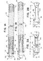
- FIG. 1A is an illustration of an implant 10a including an embolic coil 12 with a lumen 13 therethrough, a detachment feature 18a, and a stretch resistant fiber 16. Portions of the coil 12 and welds 42 as illustrated in a cut-away view for the purposes of illustration.
- the detachment feature 18a can partially be positioned within the lumen 13 of the coil 12 and can extend out of the coil 12.
- the detachment feature 18a can include a distal opening 24a through which the stretch resistant wire 16 is looped, and a proximal opening 22a sized to receive a loop wire or other engagement mechanism of a mechanical implant engagement system.
- the detachment feature 18a can include a bridge 28a positioned between the distal opening 24a and the proximal opening 22a.
- the detachment feature 18a can include a proximal tab 38 sized to fit within a lumen of a delivery tube.
- the stretch resistant fiber 16 can be secured at an end of the embolic coil 12 opposite the end to which the detachment feature 18a is attached with a weld 44 or other appropriate attachment.
- the detachment feature 18a can be tapered as it extends further within the lumen 13 of the embolic coil 12 to allow the embolic coil 12 to have additional flexibility where the embolic coil 12 surrounds the tapered region.
- the detachment feature 18a can also have a substantially flat profile, providing even greater flexibility in directions into and out of the plane of the image.
- the detachment feature 18a can be sufficiently secured with attachments 42 to the coil 12 without fusing any windings of the coil 12 (as illustrated) or by fusing a small number of windings (e.g. 5 or fewer windings).
- a small number of windings e.g. 5 or fewer windings.
- the attachments 42 to the coil 12 can be realized with significantly fewer fused coil windings.
- the proximal section of the implant 10a can have increased flexibility compared to known designs which rely on fusing windings from the proximal end of the embolic coil.
- FIG. 1B is an illustration of an alternatively constructed implant 10b having elements as described in relation to FIG. 1A with like reference numbers indicating like elements. Portions of the coil 12 and welds 42 as illustrated in a cut-away view for the purposes of illustration.
- the implant 10b can have an alternative detachment feature 18b having a single opening 26b that provides an opening to which a mechanical engagement system can engage and through which the stretch resistant fiber 16 can be looped.
- the detachment feature 18b illustrated in FIG. 1B also lacks the extended tapered region of the detachment feature 18a illustrated in FIG. 1A . Although the tapered region of the detachment feature 18a illustrated in FIG.
- the detachment feature 18b illustrated in FIG. 1B can nevertheless provide greater flexibility over known embolic coil implants by providing flexibility in directions into and out of the plane of the image by virtue of being flat and provide increased flexibility over designs which rely on fusing windings from the proximal end of the embolic coil by virtue of the low profile attachments 42.
- FIGs. 2A and 2B through FIG. 7 illustrate a sequence of steps for constructing the implants 10a and 10b illustrated in FIGs. 1A and 1B.
- FIGs. 2A and 2B illustrate the stretch resistant fiber 16 being passed through the detachment features 18a, 18b.
- the detachment features 18a, 18b can be laser cut from a flat sheet material.
- the flat sheet material is preferably a radiopaque material that can be welded or otherwise affixed to the embolic coil 12.
- FIG. 2A illustrates the dual opening detachment feature 18a having a proximal portion 32 that is sized to engage a mechanical engagement system and/or delivery tube.
- the proximal portion 32 is illustrated as having a width W1.
- the dual opening detachment feature 18a can have a distal portion 34 that is sized to fit within the lumen 13 of the embolic coil.
- the distal portion 34 can have a wider section having a width W2 that is about as wide as the inner diameter of the embolic coil 12 and a tapered section having a width W3 that is significantly narrower than the inner diameter of the embolic coil 12.
- the detachment feature 18a can have a proximal tab 38 that is narrower than the proximal portion 32 and is sized to fit within a lumen of a delivery tube.
- FIG. 2B illustrates a single opening detachment feature 18b having a proximal portion 32 that is sized to engage a mechanical engagement system and/or delivery tube.
- the proximal portion 32 is illustrated having a width W1.
- the single opening detachment feature 18b can have a distal portion 34b narrower than the proximal portion 32 and sized to fit within the lumen 13 of the coil 12.
- the single opening detachment feature 18b can have a proximal tab 38 that is narrower than the proximal portion 32 and sized to fit within a lumen of a delivery tube.
- the stretch resistant fiber 16 can be threaded through the distal opening 24a of the dual opening detachment feature 18a or the single opening 26b of the single opening detachment feature 18b.
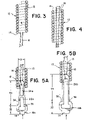
- FIG. 3 is an illustration of the free ends of the stretch resistant fiber 16 being inserted into the proximal end 15 of the embolic coil 12.
- the stretch resistant fiber 16 can be looped through a detachment feature 10a, 10b such as illustrated in FIGs. 2A and 2B .
- FIG. 4 is an illustration of the free ends of the stretch resistant fiber 16 exiting the lumen 13 of an embolic coil 12 at the distal end 14 of the embolic coil 12.
- FIGs. 5A and 5B are illustrations of detachment features 18a, 18b being inserted into the lumen 13 of an embolic coil 12.
- the free ends of the stretch resistant fiber 16 can be further pulled as indicated by the arrow in FIG. 4 to move the detachment feature 18a, 18b into the lumen 13 of the embolic coil 12 at the proximal end 15 of the embolic coil 12 as illustrated in FIGs. 5A and 5B and as indicated by the arrows.
- the embolic coil Before entry of the detachment feature 18a, 18b into the lumen 13 of the embolic coil 12, the embolic coil can have an inner diameter D as indicated in FIG. 5A .
- the proximal portion 34 of the detachment feature 18a, 18b can be sized to have a width over at least a portion of the distal portion 34 that is about equal to the inner diameter D for a snug fit.
- at least a portion of the distal portion 34 can have a width that is larger than the diameter D to create an interference fit.
- at least a portion of the distal portion 34 can have a width that is smaller than the diameter D to allow for greater flexibility of the coil 12 near the proximal end 15 of the coil 12.
- FIGs. 6A and 6B are illustrations of the detachment features 10a, 10b with the distal portion 34 fully inserted into the lumen 13 of the embolic coil 12 and the detachment feature 18a, 18b affixed to the embolic coil 12 with welds 42 or other attachment.
- the detachment feature 18a, 18b is illustrated having a distal portion 34 that has a width over at least a portion of the length of the distal portion 34 that is about equal to the inner diameter D of the lumen 13 of the embolic coil 12.
- FIG. 7 is an illustration of the stretch resistant fiber 16 affixed to the distal end of the embolic coil 12. After affixing the detachment feature 18a, 18b, or at least positioning the detachment feature 18a to 18b as illustrated in FIGs. 6A and 6B , the stretch resistant fiber 16 can be pulled tight to reduce slack in the fiber 16 and/or create tension in the fiber 16, and the fiber 16 can be affixed with a weld 44 or other attachment.
- the fiber can be substantially stretch resistant as to resist significant elongation due to forces applied to the embolic coil 12 during preparation for treatment, during delivery of the implant 10a, 10b, during positioning of the implant in a treatment site, during retraction of the implant, and during deployment of the implant.
- the stretch resistant fiber 16 can be effective to limit lengthening of the embolic coil 12 when the embolic coil 12 is retracted from an aneurysm, and the stretch resistant fiber 16 can be effective to limit separation of the windings within the embolic coil 12 when the embolic coil 12 is bent.
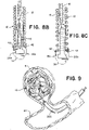
- FIGs. 8A through 8C illustrate a time sequence wherein the embolic coil 12 is allowed to stretch as a result of a non-optimal stretch resistant fiber 16 placement.
- FIG. 8A illustrates a non-optimal fiber 16 placement within the single opening detachment feature 18b.
- the fiber 16 can become looped over a section of the detachment feature 18b that is not optimal such that movement of the fiber 16 as illustrated in FIG. 8B can cause the fiber 16 to disengage from the non-optimal position, and as illustrated in FIG. 8C , can allow the embolic coil 12 to stretch at least until the fiber 16 again becomes engaged to the detachment feature 18a.
- a manufacturing challenge is therefore to prevent the fiber 16 from being positioned at a non-optimal location such as illustrated in FIG.
- the embolic coil 12 can elongate as illustrated in FIG. 8C or otherwise deform.
- An advantage of the dual opening detachment feature 18a is that the stretch resistant fiber 16 is less likely to become looped over a non-optimal section of the detachment feature 18a during manufacturing of the implant 10a illustrated in FIG. 1A .
- FIG. 9 is an illustration of embolic implant(s) 10 being delivered through a delivery catheter 200 and positioned within an aneurysm A on a blood vessel BV.
- the implant(s) can loop and bend within the aneurysm sac to form a thrombotic mass.
- the implant(s) can loop back on themselves and/or loop next to other implants. As the aneurysm A becomes increasingly packed, overlapping portions of the implant 10 can press into each other.
- FIG. 10A is an illustration of embolic coils 12 that lack a stretch resistant fiber 16 becoming tangled as overlapping portions of the coils press into each other. This entanglement can make it difficult or impossible for either of the coils 12 to be repositioned, which is a known problem with some current embolic coil implants.
- FIG. 10B illustrates a portion of the embolic coil 12 becoming elongated to a length L2 that is longer than the length L1 of that section illustrated in FIG. 10A due to a force F.
- FIG. 10B illustrates a portion of the embolic coil 12 becoming elongated to a length L2 that is longer than the length L1 of that section illustrated in FIG. 10A due to a force F.
- FIG. 10B illustrates a scenario wherein a physician may try to attempt to retract a tangled partially implanted embolic coil and may be not only unable to retract the coil but also exacerbate the already challenging treatment by now having to position the deformed elongated coil. Entanglement can become more likely when the windings of the embolic coil are separated, for example due to bending, or when the coils are more tightly pressed together due to dense packing.
- FIG. 11 is an illustration of example embolic coils 12 each having a stretch resistant fiber 16 being prevented from tangling and from elongating according to an aspect of the present invention.
- Each coil 12 is illustrated as having a bent portion 20.
- the stretch resistant fiber 16 can shift within the lumen 13 of each coil to allow the coil 12 to flex and bend as needed when implanted.
- the fiber 16 can have sufficient tension to limit the amount of separation between windings in the bent portions 20.
- the separation of the winds can be so limited as to inhibit the windings of two adjacent coils 12 from becoming entangled as illustrated in FIG. 10A .
- FIG. 11 also illustrates the force F applied to a portion 40 of the coil 12 and the portion 40 being inhibited from elongating due to tension in the stretch resistant fiber 16.
- FIG. 11 illustrates a scenario wherein a physician may successfully retract a partially implanted embolic coil 12 having a stretch resistant fiber 16 therethrough.
- FIG. 12 is a flow diagram illustrating a method 500 including steps that can be conducted as part of an aneurysm treatment using an example implant 10, 10a, 10b such as described herein.
- an implant having an embolic coil and stretch resistant fiber can be positioned at least partially within an aneurysm sac.
- a portion of the embolic coil can be bent.
- the stretch resistant fiber can inhibit separation of windings within the bent portion of the embolic coil.
- step 540 some or all of the implanted portion of the implant can be retracted from the aneurysm.
- the stretch resistant fiber can inhibit lengthening of the embolic coil.
- FIG. 13 is an illustration of an example embolic implant 10 such as either implant 10a, 10b illustrated in FIGs. 1A and 1B or otherwise described herein secured to a delivery tube 300.
- Example delivery tubes and engagement/deployment systems are described in U.S. Patent 10,806,461 and U.S. Patent 10,806,462 each incorporated herein by reference.
- the delivery tube 300 can include a notch 310 sized to receive the proximal portion 32 of the detachment feature 18 of the implant 10, and likewise the proximal portion 32 of the detachment feature 18 can be sized to fit within the notch 310 of the delivery tube 300.
- FIG. 13 illustrates a side view of the implant 10 highlighting the flat profile of the detachment feature 18.
- the implant 10 can have a highly flexible proximal section by virtue of the detachment feature 18 being flat and/or by virtue of the detachment feature 18 being secured to the coil 12 without fusing several coil windings.
- the detachment feature 18 can also be tapered for increased flexibility in directions into and out of the plane of the image.
- the detachment feature 18 can further include a proximal tab 38 positioned within the lumen of the delivery tube 300.
- An object of the present invention is to provide an implant 10 having a highly flexible proximal section and/or configured to mate with a delivery tube 300 having a highly flexible distal portion.
- FIG. 14A is an illustration of the implant 10 and delivery tube 300 configured for delivery and positioning of the implant 10.
- FIGs. 14B through 14D are illustrations of a sequence of steps for releasing the example embolic implant 10 from the delivery tube 300. A portion of the delivery tube 300 is cut away for illustration purposes.
- FIG. 14A illustrates the engagement system including a pull wire 140 and a loop wire 400 locked into the detachment feature 18 of the implant 12.
- the delivery tube 300 can include a compressible portion 306 that can be compressed.
- the loop wire 400 can have an opening 405 at a distal end 404 of the loop wire 400, and the opening 405 can be placed through an opening 22a in the detachment feature 18. When the pull wire 140 is put through the opening 405 the implant 12 is now secure.
- the detachment feature 18 can include a bridge 28 positioned distally from the loop wire opening 405 and positioned to support a distal portion of the pull wire 140 that is distal of where the loop wire opening 405 is supported by the pull wire 140.
- the bridge 28 can support the distal portion of the pull wire 140 such that when the loop wire 400 tugs on the pull wire 140 at the loop opening 405, the bridge 28 can inhibit the distal portion of the pull wire 140 from deforming.
- the proximal tab 38 can positioned to support a portion of the pull wire 140 that is proximal of where the loop wire opening 405 is supported by the pull wire 140. The combination of the bridge 28 and the proximal tab 38 can inhibit the pull wire 140 from deforming due to forces applied by the loop wire 400.
- the delivery tube 300 can be detachably attached to the implant 10 as illustrated in FIG. 14A during delivery of the implant 10 through the vasculature and while the implant 10 is being positioned at a treatment site.
- the bridge 28 can reduce the likelihood that the implant 10 is prematurely released due to bending of the pull wire 140 due to forces from the loop wire 400.
- the bridge 28 can separate a proximal opening 22a and a distal opening 24a in a dual opening implant as illustrated. It is also contemplated that a single opening implant can be adapted to include a structure that can function to support the distal portion of the pull wire 140 similar to as described in relation to the illustrated bridge 28. Alternative bridge structures are therefore intended to be within the scope of the present invention.
- FIG. 14B illustrates the pull wire 140 being drawn proximally to begin the release sequence for the implant 10.
- FIG. 14C illustrates the instant the pull wire 140 exits the opening 405 and is pulled free of the loop wire 400.
- the distal end 404 of the loop wire 400 falls away and exits the locking portion 18.
- FIG. 14D illustrates the end of the release sequence.
- the compressible portion 306 has expanded/returned to its original shape and "sprung” forward.
- An elastic force E is imparted by the distal end 304 of the delivery tube 300 to the medical device 10 to "push" it away to ensure a clean separation and delivery of the medical device 10.
- FIG. 15 is a cross sectional illustration of a proximal section of an alternatively constructed implant 10c having elements as described in relation to FIG. 1A with like reference numbers indicating like elements.
- the implant 10c illustrated in FIG. 15 can have an alternative detachment feature 18c.
- the detachment feature 18c illustrated in FIG. 18c can have a portion with a width D2 sized to fit within a lumen 13 of an embolic coil 12 having an inner diameter D1.
- the width D2 of the detachment feature 18c can be larger than the inner diameter D1 of the coil lumen 13 so that when the detachment feature 18c is positioned within the lumen 13, a proximal portion of the lumen 13 expands to a diameter D2 to accommodate the width D2 of the detachment feature 18c.
- the expanded portion of the coil 12 can provide a compressive force against the section of the detachment feature having width D2 to help secure the detachment feature 18c to the coil 12.
- the bridge 28c can extend proximally from a proximal end of the embolic coil 12.
- the pull wire 140 need not be inserted into the lumen 13 of the embolic coil 12 to be supported by the bridge 28c. Limiting the length of pull wire 140 that is inserted into the embolic coil 12 can increase the flexibility of the proximal section of the embolic coil.
- the implant 10c illustrated in FIG. 15 can be constructed according to the principles illustrated in FIGs. 2A and 2B through FIG. 7 .
- the implant 10c illustrated in FIG. 15 can be used according to the principles illustrated in FIGs. 9 and 11 through 14D .
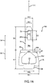
- FIG. 16 is an illustration of another example detachment feature 18d.
- Various dimensions of the detachment feature 18d are illustrated in FIG. 16 . The dimensions can be selected based on design criteria, so that the detachment feature 18d can be customized for a given implant.
- FIGs. 17A through 17H are illustrations of example detachment features having a similar general structure of the detachment feature 18d illustrated in FIG. 16 with the various dimensions illustrated in FIG. 16 adjusted to customize the detachment feature 18d.
- the detachment feature is oriented in relation to a longitudinal axis L-L, a distal direction 54, and a proximal direction 52.
- the proximal portion 32 of the detachment feature 18d has a first width W1 near a proximal end of the detachment feature 18d that is sized to fit within notches 310 of the delivery tube 300.
- the first width W1 is preferably sized approximately equal to an outer diameter of the distal end 304 of the delivery tube 300.
- the distal portion 34 of the detachment feature 18d has a second width W2 and a third width W3 similar to as disclosed in relation to FIGs. 2A and 15 .
- the proximal portion 32 of the detachment feature 18d has a fourth width W4 near engagement surfaces 36a, 36b of the detachment feature 18d.
- the fourth width W4 is preferably sized approximately equal to an outer diameter of the embolic coil 12.
- a distal opening 24d of the detachment feature 18d has a fifth width W5.
- the fifth width W5 is sufficiently wide to allow insertion of the stretch resistant fiber 16 and narrow enough to allow for sufficient material of the distal portion 34 of the detachment feature 18d to maintain structural integrity.
- the proximal extension 38 of the detachment feature 18d has a sixth width W6.
- the sixth width W6 is preferably sized about equal to, and less than a diameter of the lumen of the delivery tube 300 at the distal end 304 of the delivery tube 300.
- the proximal portion 32 of the detachment feature 18d has a third length L3.
- the third length L3 is preferably sized about equal to, and greater than a depth of the notches 310 of the delivery tube 300.
- the distal portion 34 of the detachment feature 18d has a fourth length L4.
- the fourth length L4 is preferably sized sufficiently long enough to facilitate assembly of the implant 10, maintain structural integrity of the implant 10, and provide sufficient material for the distal opening 24d and bridge 28d.
- the fourth length L4 is preferably sufficiently short to allow for flexibility of the proximal portion of the implant 10.
- a distal opening 24d of the detachment feature 18d has a fifth length L5.
- the fifth length L5 is sufficiently long to allow insertion of the stretch resistant fiber 16 and short enough so that the fourth length L4 can be sufficiently short.
- the detachment feature 18d can include a longitudinal offset between engagement surfaces 36a, 36b.
- the longitudinal offset (sixth length L6) is preferably sized approximately equal to one half a diameter D3 ( FIG. 15 ) of the wire which winds to make the embolic coil 12.
- the distal opening 24d can include an atraumatic surface 25 in contact with the stretch resistant fiber when the implant 10 is assembled.
- the atraumatic surface 25 can be shaped to reduce likelihood of abrasion of the stretch resistant fiber 16 by the detachment feature 18d.
- the proximal opening 22d can include an atraumatic surface 23 shaped to reduce likelihood of abrasion of the loop wire 400 by the detachment feature 18d.
- FIG. 18 is an illustration of the proximal portion 32d of the example detachment feature 18d illustrated in FIG 16 .
- the proximal opening 22d is approximately a five sided polygon with a base having the atraumatic surface 23 and four, distally extending sides 30 which are approximately equal in length. Corners of the polygon are rounded. Corners 27 adjacent to the atraumatic surface 23 (polygon base) can be deepened to encourage the loop wire 400 to rest in the deepened corners 27.
- the terms “about” or “approximately” for any numerical values or ranges indicate a suitable dimensional tolerance that allows the part or collection of components to function for its intended purpose as described herein. More specifically, “about” or “approximately” may refer to the range of values ⁇ 20% of the recited value, e.g. "about 90%” may refer to the range of values from 71% to 99%.
Landscapes
- Health & Medical Sciences (AREA)
- Surgery (AREA)
- Life Sciences & Earth Sciences (AREA)
- Heart & Thoracic Surgery (AREA)
- Molecular Biology (AREA)
- Vascular Medicine (AREA)
- Engineering & Computer Science (AREA)
- Biomedical Technology (AREA)
- Reproductive Health (AREA)
- Medical Informatics (AREA)
- Nuclear Medicine, Radiotherapy & Molecular Imaging (AREA)
- Animal Behavior & Ethology (AREA)
- General Health & Medical Sciences (AREA)
- Public Health (AREA)
- Veterinary Medicine (AREA)
- Neurosurgery (AREA)
- Surgical Instruments (AREA)
Abstract
Description
- This application is a continuation in part to prior filed
U.S. Patent Application No. 16/573,469 filed on September 17, 2019 - The present invention generally relates to implantable medical devices, and more particularly, to engagement features for mechanically releasably securing implantable medical devices to a delivery system.
- Aneurysms can be intravascularly treated by delivering a treatment device to the aneurysm to fill the sac of the aneurysm with embolic material and/or block the neck of the aneurysm to inhibit blood flow into the aneurysm. When filling the aneurysm sac, the embolic material can promote blood clotting to create a thrombotic mass within the aneurysm. When treating the aneurysm neck without substantially filling the aneurysm sac, blood flow into the neck of the aneurysm can be inhibited to induce venous stasis in the aneurysm and facilitate natural formation of a thrombotic mass within the aneurysm.
- In some current treatments, multiple embolic coils are used to either fill the aneurysm sac or treat the entrance of the aneurysm neck. A common challenge among embolic coil treatments is that implanted coils and implanted portions of partially implanted coils can become entangled and difficult to reposition. In some instances, a physician may not be able to retract a partially implanted coil and may be forced to position the coil in a non-ideal location. Improperly positioning embolic coils at the aneurysm neck can potentially have the adverse effect of impeding the flow of blood in the adjoining blood vessel, particularly if the entrance and/or sac is overpacked. If a portion of the non-ideally implanted coil becomes dislodged, it can enter the neighboring blood vessel and promote clot formation, which can ultimately lead to an obstruction that is tethered to the aneurysm and therefor extremely difficult to treat. Conversely, if the entrance and/or sac is insufficiently packed, blood flow can persist into the aneurysm.
- In some current treatments, an embolic coil is attached to a tubular delivery member and delivered via a delivery catheter to an aneurysm. During delivery, the embolic coil can be engaged to the delivery member's implant engagement/deployment system (referred to herein equivalently as an "engagement system" or "deployment system"). When the embolic coil is in position, the deployment system can release the coil, the coil can be left implanted, and the delivery member can be retracted. Some treatments utilize a mechanical engagement/deployment system that can be actuated by a physician to release the implant by pulling one or more wires or other elongated members referred to generically herein as a "pull wire".
- Some of the challenges that have been associated with delivering and deploying embolic coils with delivery members having mechanical engagement systems include premature release of a coil and movement of the delivery member due to push back from densely packed treatment sites.
- There is therefore a need for improved methods, devices, and systems to facilitate implantation of embolic coils and other implants facing similar challenges.
- It is an object of the present invention to provide systems, devices, and methods to meet the above-stated needs. In some examples presented herein, separation of coil windings within an embolic coil is reduced or prevented with a stretch resistant fiber that is positioned within the lumen of the coil. Reducing or preventing the separation of coil windings can in some cases prevent an implanted portion of a partially implanted coil from being tangled with implanted coils and thereby make it possible to more easily reposition and/or extract some or all of the coil. In some examples presented herein, during delivery of the embolic coil the distal end of the pull wire is supported by an engagement/detachment feature (referred to herein equivalently as "engagement feature", "detachment feature", or "key") affixed to the proximal end of the embolic coil. The support provided by the key can in some cases reduce the likelihood that the embolic coil is prematurely released. In some examples presented herein, the embolic implant can have a highly flexible proximal portion. The flexibility of the embolic implant can in some cases reduce the force on the delivery member due to push back from densely packed treatment sites and thereby reduce movement of the delivery member due to the push back.
- To meet some or all of the needs, an implant having an embolic coil, a stretch resistant fiber extended through the coil, and a detachment feature / key at the coil's proximal end is provided. The stretch resistant fiber can be effective to limit separation of windings of the embolic coil. The key can provide an attachment for securing the embolic coil to an engagement system of a delivery tube and for securing the stretch resistant fiber at the proximal end of the embolic coil.
- An example method for treating an aneurysm can include one or more of the following steps presented in no particular order, and the method can include additional steps not included here. Some or all of an implant having an embolic coil and a stretch resistant fiber can be positioned within the aneurysm. A portion of the embolic coil can be retracted from the aneurysm. The portion can be inhibited from lengthening by the stretch resistant fiber when the portion is retraced from the aneurysm. The embolic coil can be bent, and the stretch resistant fiber can limit separation of the windings of the embolic coil at the bend.
- The stretch resistant fiber can be positioned to extend within a lumen of the embolic coil. The stretch resistant fiber can under tension along a majority of the length of the stretch resistant fiber.
- The implant can be secured to a delivery system with a key engaged to the stretch resistant fiber. To secure the implant to the delivery system, a loop wire of the delivery system can be positioned through the key, and a pull wire can be positioned through an opening in the loop wire. When the implant is secured to the delivery system, the pull wire can be supported by the key both in the proximal direction from the loop wire and the distal direction from the loop wire.
- During delivery and/or positioning of the implant, the key can be visualized radiographically.
- The key can be released from the delivery system, thereby releasing the implant from the delivery system. When the implant is released, the key can remain attached to the implant.
- An example embolic implant can include an embolic coil, a detachment feature, and a stretch resistant fiber. The detachment feature can be affixed to the embolic coil at the proximal end of the embolic coil. The stretch resistant fiber can be engaged to the detachment feature, extend through the lumen of the embolic coil, and can be affixed to the embolic coil at the distal end of the embolic coil. Configured thusly, the stretch resistant fiber can be effective to limit separation of windings of the embolic coil as the embolic coil is reshaped.
- The stretch resistant fiber can be a suture. The stretch resistant fiber can be inelastic.
- The detachment feature can be radiopaque.
- The detachment feature can have an opening through which the stretch resistant fiber passes. The opening can extend proximally from a proximal end of the embolic coil.
- The detachment feature can have a singular opening that is sized to receive a loop wire of a mechanical delivery system and through which the stretch resistant fiber passes.
- Alternatively, the detachment feature can have two separate openings: a first opening through which the stretch resistant fiber passes and a second opening sized to receive a loop wire of a mechanical delivery system. The first opening can be at least partially positioned within the lumen of the embolic coil. The second opening can be at least partially positioned in the proximal direction from the proximal end of the embolic coil.
- An example system can include the example embolic implant having the detachment feature with two separate openings and a mechanical delivery system including a loop wire and a pull wire. The stretch resistant fiber can pass through one of the two openings, and the loop wire can pass through the other of the two openings. The pull wire can be positioned through an opening in the loop wire, thereby securing the implant to the mechanical delivery system with the loop wire. The detachment feature can further include a bridge positioned between the two openings of the detachment feature, and the bridge can support a portion of the pull wire that is in the distal direction from the loop opening in the loop wire.
- The detachment feature can have a proximal portion disposed proximally from the lumen of the embolic coil and a distal portion disposed within the lumen. The proximal portion can have a width that measures greater than the inner diameter of the embolic coil lumen, and the distal portion can have a width that measures about equal to the inner diameter of the embolic coil lumen.
- An example method for constructing or designing an embolic implant such as an example implant as described herein can include one or more of the following steps presented in no particular order, and the method can include additional steps not included here. A detachment feature can be cut from a flat sheet material. One or more openings can be cut from the detachment feature. A stretch resistant fiber can be threaded through an opening in the detachment feature. The stretch resistant fiber can be extended through a lumen of an embolic coil. The detachment feature can be affixed at one end of the embolic coil. The stretch resistant fiber can be affixed at the other end of the embolic coil. Tension can be provided along the stretch resistant fiber between the detachment feature and the second end of the embolic coil.
- A portion of a mechanical deployment system can be extended through an opening in the detachment feature to engage the detachment feature to a delivery tube. The mechanical deployment system can be extended through the same opening through which the stretch resistant fiber is threaded or an opening in the detachment feature that is separate from the opening through which the stretch resistant fiber is threaded.
- The detachment feature can be cut from a radiopaque flat sheet material.
- A distal portion of the detachment feature can be inserted within the lumen of the embolic coil and a proximal portion of the detachment feature can be extended proximally from the proximal end of the embolic coil. The embolic coil and the detachment feature can be selected such that the proximal portion of the detachment feature is wider than the inner diameter of the embolic coil's lumen and the distal portion of the detachment feature is about equal to the inner diameter of the embolic coil's lumen.
- To affix the detachment feature to the embolic coil, the detachment feature can be welded to the embolic coil.
- The above and further aspects of this invention are further discussed with reference to the following description in conjunction with the accompanying drawings, in which like numerals indicate like structural elements and features in various figures. The drawings are not necessarily to scale, emphasis instead being placed upon illustrating principles of the invention. The figures depict one or more implementations of the inventive devices, by way of example only, not by way of limitation.
-
FIGs. 1A and 1B are illustrations of embolic implants according to aspects of the present invention; -
FIGs. 2A and 2B are illustrations of detachment features each having a stretch resistant fiber therethrough according to aspects of the present invention; -
FIG. 3 is an illustration of a stretch resistant fiber being inserted into a lumen of an embolic coil according to aspects of the present invention; -
FIG. 4 is an illustration of a stretch resistant fiber exiting a lumen of an embolic coil according to aspects of the present invention; -
FIGs. 5A and 5B are illustrations of detachment features being inserted into a lumen of an embolic coil according to aspects of the present invention; -
FIGs. 6A and 6B are illustrations of detachment features affixed to an embolic coil according to aspects of the present invention; -
FIG. 7 is an illustration of the stretch resistant fiber affixed to an end of the embolic coil according to aspects of the present invention; -
FIGs. 8A through 8C illustrate a time sequence wherein an embolic coil stretches as a result of a non-optimal stretch resistant fiber placement; -
FIG. 9 is an illustration of embolic coils being positioned within an aneurysm according to aspects of the present invention; -
FIG. 10A is an illustration of embolic coils becoming tangled, and -
FIG. 10B is an illustration of a tangled coil becoming elongated as illustrations of a problem with the prior art; -
FIG. 11 is an illustration of a stretch resistant fiber inhibiting tangling and elongating of an embolic coil according to aspects of the present invention; -
FIG. 12 is a flow diagram outlining method steps that can be conducted as part of an aneurysm treatment according to aspects of the present invention; -
FIG. 13 is an illustration of an embolic implant secured to a delivery tube according to aspects of the present invention; -
FIGs. 14A through 14D illustrate a sequence of steps for releasing an embolic implant from a delivery tube according to aspects of the present invention; -
FIG. 15 is an illustration of an end of an embolic implant including a detachment feature expanding an inner diameter of an embolic coil according to aspects of the present invention; -
FIG. 16 is an illustration of another example detachment feature according to aspects of the present invention; -
FIGs. 17A through 17H are illustrations of example detachment features according to aspects of the present invention; and -
FIG. 18 is an illustration of a proximal portion of the example detachment feature illustrated inFIG 16 according at aspects of the present invention. - An object of the present invention is to attain more precise and repeatable implant detachment. More specifically, it is an object of the present invention to facilitate implantation of embolic coils and other implants facing challenges such as partially implanted implants becoming difficult to reposition, delivery systems shifting position due to push back during implantation, and/or implants releasing prematurely. To meet some or all of these needs, example implants can include a stretch resistant fiber to limit stretching and other deformation of the embolic portion (e.g. embolic coil) of the implant and a detachment feature to which the stretch resistant fiber can be secured and to which a delivery system can detachably attach.
- To facilitate repositioning of the implant, the stretch resistant fiber can extend through the embolic coil and limit separation of windings of the coil when the coil is bent and pulled. By limiting the separation of the windings, the embolic coil is less likely to become tangled when partially implanted and less likely to be stretched or otherwise deformed when retracted when partially implanted. The embolic coil can thereby be more easily repositioned. In some examples, the detachment feature can include two separate openings, one for securing the stretch resistant fiber, and another for being engaged to an engagement system. The dual opening detachment feature can reduce potential manufacturing challenges to provide for reliable stretch resistant fiber positioning and therefore more reliably provide implants that can be more easily repositioned.
- To reduce effects of push back during implantation, the detachment feature can be sized and affixed to the embolic coil to provide an embolic coil implant with a highly flexible proximal section. An embolic coil implant having a highly flexible proximal section can reduce push back force on the delivery tube and thereby mitigate the effects of the delivery tube shifting. Additionally, or alternatively, the detachment feature can be sized to mate with a delivery tube having a highly flexible distal section, and the highly flexible distal section of the delivery tube can mitigate the effects of the delivery tube shifting. When an embolic coil implant having a highly flexible proximal section is mated to a delivery tube having a highly flexible distal portion, the combination of the flexible distal section of the delivery tube and the flexible proximal section of the implant can further mitigate the effects of delivery tube shifting.
- To reduce instances of premature deployment, the detachment feature can include a bridge to support a pull wire. The detachment feature can be detachably attached to a mechanical engagement/deployment system on a delivery tube. The detachment feature can include an opening through which a loop wire of a mechanical engagement system can pass. In some examples, the detachment feature can further include a bridge positioned distally from the opening on which a distal portion of the pull wire can rest. The bridge can inhibit the pull wire from deforming due to the engagement with the loop wire and can therefore reduce the likelihood that the implant is prematurely released due to bending of the pull wire.
-
FIG. 1A is an illustration of animplant 10a including anembolic coil 12 with alumen 13 therethrough, adetachment feature 18a, and a stretchresistant fiber 16. Portions of thecoil 12 and welds 42 as illustrated in a cut-away view for the purposes of illustration. Thedetachment feature 18a can partially be positioned within thelumen 13 of thecoil 12 and can extend out of thecoil 12. Thedetachment feature 18a can include adistal opening 24a through which the stretchresistant wire 16 is looped, and aproximal opening 22a sized to receive a loop wire or other engagement mechanism of a mechanical implant engagement system. Thedetachment feature 18a can include abridge 28a positioned between thedistal opening 24a and theproximal opening 22a. Thedetachment feature 18a can include aproximal tab 38 sized to fit within a lumen of a delivery tube. The stretchresistant fiber 16 can be secured at an end of theembolic coil 12 opposite the end to which thedetachment feature 18a is attached with aweld 44 or other appropriate attachment. - The
detachment feature 18a can be tapered as it extends further within thelumen 13 of theembolic coil 12 to allow theembolic coil 12 to have additional flexibility where theembolic coil 12 surrounds the tapered region. Thedetachment feature 18a can also have a substantially flat profile, providing even greater flexibility in directions into and out of the plane of the image. - The
detachment feature 18a can be sufficiently secured withattachments 42 to thecoil 12 without fusing any windings of the coil 12 (as illustrated) or by fusing a small number of windings (e.g. 5 or fewer windings). Compared to known solutions wherein typically ten or more windings are soldered together (with limited control over the number of fused windings), theattachments 42 to thecoil 12 can be realized with significantly fewer fused coil windings. By reducing the number of windings that are fused, the proximal section of theimplant 10a can have increased flexibility compared to known designs which rely on fusing windings from the proximal end of the embolic coil. -
FIG. 1B is an illustration of an alternatively constructed implant 10b having elements as described in relation toFIG. 1A with like reference numbers indicating like elements. Portions of thecoil 12 and welds 42 as illustrated in a cut-away view for the purposes of illustration. Compared to theimplant 10a illustrated inFIG. 1A , the implant 10b can have analternative detachment feature 18b having asingle opening 26b that provides an opening to which a mechanical engagement system can engage and through which the stretchresistant fiber 16 can be looped. Thedetachment feature 18b illustrated inFIG. 1B also lacks the extended tapered region of thedetachment feature 18a illustrated inFIG. 1A . Although the tapered region of thedetachment feature 18a illustrated inFIG. 1A can provide for a more flexible proximal section of theimplant 10a compared to the implant 10b inFIG. 1B , thedetachment feature 18b illustrated inFIG. 1B can nevertheless provide greater flexibility over known embolic coil implants by providing flexibility in directions into and out of the plane of the image by virtue of being flat and provide increased flexibility over designs which rely on fusing windings from the proximal end of the embolic coil by virtue of thelow profile attachments 42. -
FIGs. 2A and 2B throughFIG. 7 illustrate a sequence of steps for constructing theimplants 10a and 10b illustrated inFIGs. 1A and 1B. FIGs. 2A and 2B illustrate the stretchresistant fiber 16 being passed through the detachment features 18a, 18b. The detachment features 18a, 18b can be laser cut from a flat sheet material. The flat sheet material is preferably a radiopaque material that can be welded or otherwise affixed to theembolic coil 12. -
FIG. 2A illustrates the dualopening detachment feature 18a having aproximal portion 32 that is sized to engage a mechanical engagement system and/or delivery tube. Theproximal portion 32 is illustrated as having a width W1. The dualopening detachment feature 18a can have adistal portion 34 that is sized to fit within thelumen 13 of the embolic coil. Thedistal portion 34 can have a wider section having a width W2 that is about as wide as the inner diameter of theembolic coil 12 and a tapered section having a width W3 that is significantly narrower than the inner diameter of theembolic coil 12. Thedetachment feature 18a can have aproximal tab 38 that is narrower than theproximal portion 32 and is sized to fit within a lumen of a delivery tube. -
FIG. 2B illustrates a singleopening detachment feature 18b having aproximal portion 32 that is sized to engage a mechanical engagement system and/or delivery tube. Theproximal portion 32 is illustrated having a width W1. The singleopening detachment feature 18b can have a distal portion 34b narrower than theproximal portion 32 and sized to fit within thelumen 13 of thecoil 12. The singleopening detachment feature 18b can have aproximal tab 38 that is narrower than theproximal portion 32 and sized to fit within a lumen of a delivery tube. - After the
detachment feature resistant fiber 16 can be threaded through thedistal opening 24a of the dualopening detachment feature 18a or thesingle opening 26b of the singleopening detachment feature 18b. -
FIG. 3 is an illustration of the free ends of the stretchresistant fiber 16 being inserted into theproximal end 15 of theembolic coil 12. At the step illustrated inFIG. 3 , the stretchresistant fiber 16 can be looped through adetachment feature 10a, 10b such as illustrated inFIGs. 2A and 2B . -
FIG. 4 is an illustration of the free ends of the stretchresistant fiber 16 exiting thelumen 13 of anembolic coil 12 at thedistal end 14 of theembolic coil 12. -
FIGs. 5A and 5B are illustrations of detachment features 18a, 18b being inserted into thelumen 13 of anembolic coil 12. After exiting thedistal end 14 of theembolic coil 12, the free ends of the stretchresistant fiber 16 can be further pulled as indicated by the arrow inFIG. 4 to move thedetachment feature lumen 13 of theembolic coil 12 at theproximal end 15 of theembolic coil 12 as illustrated inFIGs. 5A and 5B and as indicated by the arrows. Before entry of thedetachment feature lumen 13 of theembolic coil 12, the embolic coil can have an inner diameter D as indicated inFIG. 5A . Theproximal portion 34 of thedetachment feature distal portion 34 that is about equal to the inner diameter D for a snug fit. Alternatively, or additionally, at least a portion of thedistal portion 34 can have a width that is larger than the diameter D to create an interference fit. Alternatively, or additionally, at least a portion of thedistal portion 34 can have a width that is smaller than the diameter D to allow for greater flexibility of thecoil 12 near theproximal end 15 of thecoil 12. -
FIGs. 6A and 6B are illustrations of the detachment features 10a, 10b with thedistal portion 34 fully inserted into thelumen 13 of theembolic coil 12 and thedetachment feature embolic coil 12 withwelds 42 or other attachment. In bothFIGs. 6A and 6B , thedetachment feature distal portion 34 that has a width over at least a portion of the length of thedistal portion 34 that is about equal to the inner diameter D of thelumen 13 of theembolic coil 12. -
FIG. 7 is an illustration of the stretchresistant fiber 16 affixed to the distal end of theembolic coil 12. After affixing thedetachment feature detachment feature 18a to 18b as illustrated inFIGs. 6A and 6B , the stretchresistant fiber 16 can be pulled tight to reduce slack in thefiber 16 and/or create tension in thefiber 16, and thefiber 16 can be affixed with aweld 44 or other attachment. After thefiber 16 is attached, the fiber can be substantially stretch resistant as to resist significant elongation due to forces applied to theembolic coil 12 during preparation for treatment, during delivery of theimplant 10a, 10b, during positioning of the implant in a treatment site, during retraction of the implant, and during deployment of the implant. In other words, the stretchresistant fiber 16 can be effective to limit lengthening of theembolic coil 12 when theembolic coil 12 is retracted from an aneurysm, and the stretchresistant fiber 16 can be effective to limit separation of the windings within theembolic coil 12 when theembolic coil 12 is bent. -
FIGs. 8A through 8C illustrate a time sequence wherein theembolic coil 12 is allowed to stretch as a result of a non-optimal stretchresistant fiber 16 placement.FIG. 8A illustrates anon-optimal fiber 16 placement within the singleopening detachment feature 18b. Thefiber 16 can become looped over a section of thedetachment feature 18b that is not optimal such that movement of thefiber 16 as illustrated inFIG. 8B can cause thefiber 16 to disengage from the non-optimal position, and as illustrated inFIG. 8C , can allow theembolic coil 12 to stretch at least until thefiber 16 again becomes engaged to thedetachment feature 18a. A manufacturing challenge is therefore to prevent thefiber 16 from being positioned at a non-optimal location such as illustrated inFIG. 8A when the attachment step illustrated inFIG. 7 is performed. If, after manufacturing is complete, thefiber 16 becomes dislodged from the non-optimal location as illustrated inFIG. 8B , when the implant 10b is manipulated, such as while being repositioned during a treatment, theembolic coil 12 can elongate as illustrated inFIG. 8C or otherwise deform. - An advantage of the dual
opening detachment feature 18a is that the stretchresistant fiber 16 is less likely to become looped over a non-optimal section of thedetachment feature 18a during manufacturing of theimplant 10a illustrated inFIG. 1A . -
FIG. 9 is an illustration of embolic implant(s) 10 being delivered through adelivery catheter 200 and positioned within an aneurysm A on a blood vessel BV. The implant(s) can loop and bend within the aneurysm sac to form a thrombotic mass. The implant(s) can loop back on themselves and/or loop next to other implants. As the aneurysm A becomes increasingly packed, overlapping portions of theimplant 10 can press into each other. -
FIG. 10A is an illustration ofembolic coils 12 that lack a stretchresistant fiber 16 becoming tangled as overlapping portions of the coils press into each other. This entanglement can make it difficult or impossible for either of thecoils 12 to be repositioned, which is a known problem with some current embolic coil implants.FIG. 10B illustrates a portion of theembolic coil 12 becoming elongated to a length L2 that is longer than the length L1 of that section illustrated inFIG. 10A due to a force F.FIG. 10B illustrates a scenario wherein a physician may try to attempt to retract a tangled partially implanted embolic coil and may be not only unable to retract the coil but also exacerbate the already challenging treatment by now having to position the deformed elongated coil. Entanglement can become more likely when the windings of the embolic coil are separated, for example due to bending, or when the coils are more tightly pressed together due to dense packing. -
FIG. 11 is an illustration of example embolic coils 12 each having a stretchresistant fiber 16 being prevented from tangling and from elongating according to an aspect of the present invention. Eachcoil 12 is illustrated as having abent portion 20. The stretchresistant fiber 16 can shift within thelumen 13 of each coil to allow thecoil 12 to flex and bend as needed when implanted. Thefiber 16 can have sufficient tension to limit the amount of separation between windings in thebent portions 20. The separation of the winds can be so limited as to inhibit the windings of twoadjacent coils 12 from becoming entangled as illustrated inFIG. 10A .FIG. 11 also illustrates the force F applied to aportion 40 of thecoil 12 and theportion 40 being inhibited from elongating due to tension in the stretchresistant fiber 16.FIG. 11 illustrates a scenario wherein a physician may successfully retract a partially implantedembolic coil 12 having a stretchresistant fiber 16 therethrough. -
FIG. 12 is a flow diagram illustrating amethod 500 including steps that can be conducted as part of an aneurysm treatment using anexample implant step 510, an implant having an embolic coil and stretch resistant fiber can be positioned at least partially within an aneurysm sac. Instep 520, a portion of the embolic coil can be bent. Instep 530, as the coil is bent, the stretch resistant fiber can inhibit separation of windings within the bent portion of the embolic coil. Instep 540, some or all of the implanted portion of the implant can be retracted from the aneurysm. Instep 550, as the implant is retracted, the stretch resistant fiber can inhibit lengthening of the embolic coil. -
FIG. 13 is an illustration of an exampleembolic implant 10 such as eitherimplant 10a, 10b illustrated inFIGs. 1A and 1B or otherwise described herein secured to adelivery tube 300. Example delivery tubes and engagement/deployment systems are described inU.S. Patent 10,806,461 U.S. Patent 10,806,462 delivery tube 300 can include anotch 310 sized to receive theproximal portion 32 of thedetachment feature 18 of theimplant 10, and likewise theproximal portion 32 of thedetachment feature 18 can be sized to fit within thenotch 310 of thedelivery tube 300.FIG. 13 illustrates a side view of theimplant 10 highlighting the flat profile of thedetachment feature 18. As described in relation toFIGs. 1A and 1B , theimplant 10 can have a highly flexible proximal section by virtue of thedetachment feature 18 being flat and/or by virtue of thedetachment feature 18 being secured to thecoil 12 without fusing several coil windings. Thedetachment feature 18 can also be tapered for increased flexibility in directions into and out of the plane of the image. Thedetachment feature 18 can further include aproximal tab 38 positioned within the lumen of thedelivery tube 300. - During an aneurysm occlusion treatment, lack of flexibility of the proximal section of known embolic implants and/or lack of flexibility of a distal portion of a delivery tube can cause the delivery tube to pull back from the treatment site or otherwise move out of position while the implant is being placed in the aneurysm. A delivery tube having a more flexible distal portion and an implant having a more flexible proximal section, alone or in combination, can therefore provide a more stable system for delivering the implant. Flexible structures, however, can tend deform or expand when manipulated. The stretch
resistant fiber 16 and/ordetachment feature 18 alone or in combination can support thecoil 12 and inhibit deformation and expansion of thecoil 12 according to the principles described herein. An object of the present invention is to provide animplant 10 having a highly flexible proximal section and/or configured to mate with adelivery tube 300 having a highly flexible distal portion. -
FIG. 14A is an illustration of theimplant 10 anddelivery tube 300 configured for delivery and positioning of theimplant 10.FIGs. 14B through 14D are illustrations of a sequence of steps for releasing the exampleembolic implant 10 from thedelivery tube 300. A portion of thedelivery tube 300 is cut away for illustration purposes. -
FIG. 14A illustrates the engagement system including apull wire 140 and aloop wire 400 locked into thedetachment feature 18 of theimplant 12. Thedelivery tube 300 can include acompressible portion 306 that can be compressed. Theloop wire 400 can have anopening 405 at adistal end 404 of theloop wire 400, and theopening 405 can be placed through anopening 22a in thedetachment feature 18. When thepull wire 140 is put through theopening 405 theimplant 12 is now secure. - The
detachment feature 18 can include abridge 28 positioned distally from theloop wire opening 405 and positioned to support a distal portion of thepull wire 140 that is distal of where theloop wire opening 405 is supported by thepull wire 140. Configured thusly, thebridge 28 can support the distal portion of thepull wire 140 such that when theloop wire 400 tugs on thepull wire 140 at theloop opening 405, thebridge 28 can inhibit the distal portion of thepull wire 140 from deforming. Theproximal tab 38 can positioned to support a portion of thepull wire 140 that is proximal of where theloop wire opening 405 is supported by thepull wire 140. The combination of thebridge 28 and theproximal tab 38 can inhibit thepull wire 140 from deforming due to forces applied by theloop wire 400. Thedelivery tube 300 can be detachably attached to theimplant 10 as illustrated inFIG. 14A during delivery of theimplant 10 through the vasculature and while theimplant 10 is being positioned at a treatment site. Thebridge 28 can reduce the likelihood that theimplant 10 is prematurely released due to bending of thepull wire 140 due to forces from theloop wire 400. - The
bridge 28 can separate aproximal opening 22a and adistal opening 24a in a dual opening implant as illustrated. It is also contemplated that a single opening implant can be adapted to include a structure that can function to support the distal portion of thepull wire 140 similar to as described in relation to the illustratedbridge 28. Alternative bridge structures are therefore intended to be within the scope of the present invention. -
FIG. 14B illustrates thepull wire 140 being drawn proximally to begin the release sequence for theimplant 10.FIG. 14C illustrates the instant thepull wire 140 exits theopening 405 and is pulled free of theloop wire 400. Thedistal end 404 of theloop wire 400 falls away and exits the lockingportion 18. As can be seen, there is now nothing holding theimplant 10 to thedelivery tube 300.FIG. 14D illustrates the end of the release sequence. Here, thecompressible portion 306 has expanded/returned to its original shape and "sprung" forward. An elastic force E is imparted by thedistal end 304 of thedelivery tube 300 to themedical device 10 to "push" it away to ensure a clean separation and delivery of themedical device 10. -
FIG. 15 is a cross sectional illustration of a proximal section of an alternatively constructedimplant 10c having elements as described in relation toFIG. 1A with like reference numbers indicating like elements. Compared to theimplant 10a illustrated inFIG. 1A , theimplant 10c illustrated inFIG. 15 can have analternative detachment feature 18c. Thedetachment feature 18c illustrated in FIG. 18c can have a portion with a width D2 sized to fit within alumen 13 of anembolic coil 12 having an inner diameter D1. The width D2 of thedetachment feature 18c can be larger than the inner diameter D1 of thecoil lumen 13 so that when thedetachment feature 18c is positioned within thelumen 13, a proximal portion of thelumen 13 expands to a diameter D2 to accommodate the width D2 of thedetachment feature 18c. Configured thusly, the expanded portion of thecoil 12 can provide a compressive force against the section of the detachment feature having width D2 to help secure thedetachment feature 18c to thecoil 12. - Compared to the
implant 10a illustrated inFIG. 1A , thebridge 28c can extend proximally from a proximal end of theembolic coil 12. Configured thusly, in some configurations, thepull wire 140 need not be inserted into thelumen 13 of theembolic coil 12 to be supported by thebridge 28c. Limiting the length ofpull wire 140 that is inserted into theembolic coil 12 can increase the flexibility of the proximal section of the embolic coil. - The
implant 10c illustrated inFIG. 15 can be constructed according to the principles illustrated inFIGs. 2A and 2B throughFIG. 7 . Theimplant 10c illustrated inFIG. 15 can be used according to the principles illustrated inFIGs. 9 and11 through 14D . -
FIG. 16 is an illustration of anotherexample detachment feature 18d. Various dimensions of thedetachment feature 18d are illustrated inFIG. 16 . The dimensions can be selected based on design criteria, so that thedetachment feature 18d can be customized for a given implant.FIGs. 17A through 17H are illustrations of example detachment features having a similar general structure of thedetachment feature 18d illustrated inFIG. 16 with the various dimensions illustrated inFIG. 16 adjusted to customize thedetachment feature 18d. The detachment feature is oriented in relation to a longitudinal axis L-L, adistal direction 54, and aproximal direction 52. - The
proximal portion 32 of thedetachment feature 18d has a first width W1 near a proximal end of thedetachment feature 18d that is sized to fit withinnotches 310 of thedelivery tube 300. The first width W1 is preferably sized approximately equal to an outer diameter of thedistal end 304 of thedelivery tube 300. - The
distal portion 34 of thedetachment feature 18d has a second width W2 and a third width W3 similar to as disclosed in relation toFIGs. 2A and15 . - The
proximal portion 32 of thedetachment feature 18d has a fourth width W4 nearengagement surfaces detachment feature 18d. The fourth width W4 is preferably sized approximately equal to an outer diameter of theembolic coil 12. - A
distal opening 24d of thedetachment feature 18d has a fifth width W5. The fifth width W5 is sufficiently wide to allow insertion of the stretchresistant fiber 16 and narrow enough to allow for sufficient material of thedistal portion 34 of thedetachment feature 18d to maintain structural integrity. - The
proximal extension 38 of thedetachment feature 18d has a sixth width W6. The sixth width W6 is preferably sized about equal to, and less than a diameter of the lumen of thedelivery tube 300 at thedistal end 304 of thedelivery tube 300. - The
proximal portion 32 of thedetachment feature 18d has a third length L3. The third length L3 is preferably sized about equal to, and greater than a depth of thenotches 310 of thedelivery tube 300. - The
distal portion 34 of thedetachment feature 18d has a fourth length L4. The fourth length L4 is preferably sized sufficiently long enough to facilitate assembly of theimplant 10, maintain structural integrity of theimplant 10, and provide sufficient material for thedistal opening 24d andbridge 28d. The fourth length L4 is preferably sufficiently short to allow for flexibility of the proximal portion of theimplant 10. - A
distal opening 24d of thedetachment feature 18d has a fifth length L5. The fifth length L5 is sufficiently long to allow insertion of the stretchresistant fiber 16 and short enough so that the fourth length L4 can be sufficiently short. - The
detachment feature 18d can include a longitudinal offset betweenengagement surfaces FIG. 15 ) of the wire which winds to make theembolic coil 12. - The
distal opening 24d can include anatraumatic surface 25 in contact with the stretch resistant fiber when theimplant 10 is assembled. Theatraumatic surface 25 can be shaped to reduce likelihood of abrasion of the stretchresistant fiber 16 by thedetachment feature 18d. Likewise, theproximal opening 22d can include anatraumatic surface 23 shaped to reduce likelihood of abrasion of theloop wire 400 by thedetachment feature 18d. -
FIG. 18 is an illustration of theproximal portion 32d of theexample detachment feature 18d illustrated inFIG 16 . Theproximal opening 22d is approximately a five sided polygon with a base having theatraumatic surface 23 and four, distally extendingsides 30 which are approximately equal in length. Corners of the polygon are rounded.Corners 27 adjacent to the atraumatic surface 23 (polygon base) can be deepened to encourage theloop wire 400 to rest in the deepenedcorners 27. - As used herein, the terms "about" or "approximately" for any numerical values or ranges indicate a suitable dimensional tolerance that allows the part or collection of components to function for its intended purpose as described herein. More specifically, "about" or "approximately" may refer to the range of values ±20% of the recited value, e.g. "about 90%" may refer to the range of values from 71% to 99%.
- The descriptions contained herein are examples of embodiments of the invention and are not intended in any way to limit the scope of the invention. As described herein, the invention contemplates many variations and modifications of the implant and methods for making and using the same, including alternative materials, alternative geometries of component parts, alternative positioning of component parts in relation to each other, etc. These modifications would be apparent to those having ordinary skill in the art to which this invention relates and are intended to be within the scope of the claims which follow.
Claims (15)
- An embolic implant comprising:an embolic coil comprising a coiled wire;a detachment feature affixed to the embolic coil approximate a proximal end of the embolic coil, the detachment feature comprising a first engagement surface and a second engagement surface longitudinally offset from each other by a length approximately equal to half of a diameter of the coiled wire; anda stretch resistant fiber engaged to the detachment feature, extended through a lumen of the embolic coil, and affixed to the embolic coil approximate a distal end of the embolic coil.
- The embolic implant of claim 1, wherein the stretch resistant fiber is effective to limit separation of windings of the embolic coil as the embolic coil is reshaped.
- The embolic implant of claim 1,wherein the detachment feature comprises a first opening therethrough and a second opening therethrough separated from the first opening,wherein the stretch resistant fiber passes through the first opening,wherein at least a portion of the first opening is positioned within the lumen of the embolic coil, andwherein at least a portion of the second opening is positioned proximally from the proximal end of the embolic coil.
- The embolic implant of claim 3, wherein the second opening comprises an atraumatic surface at a distal end of the second opening, or the first opening comprises an atraumatic surface orthogonal to a longitudinal axis of the detachment feature.
- The embolic implant of claim 3, wherein the second opening comprises an approximately polygon shape comprising four sides of approximately equal length and a fifth side of greater length than the four sides, the fifth side being orthogonal to a longitudinal axis of the detachment feature, optionally wherein the polygon shape comprises two corners on either end of the fifth side that are each respectively extended in a proximal direction in relation to the fifth side.
- The embolic implant of claim 1,wherein the lumen of the embolic coil comprises an inner diameter,wherein the detachment feature comprises proximal portion disposed proximally from the lumen and a distal portion disposed within the lumen,wherein the proximal portion comprises a first width measuring greater than the inner diameter of the lumen, andwherein the distal portion comprises a second width measuring about equal to the inner diameter of the lumen.
- A system comprising:an implant comprising an embolic coil and a detachment feature, the detachment feature comprising a distal portion extended within a lumen of the embolic coil, a proximal portion extending proximally from a proximal end of the embolic coil, a first engagement surface affixed to the proximal end of the embolic coil, and a second engagement surface affixed to the proximal end of the embolic coil, the first engagement surface and the second engagement surface being longitudinally offset from each other by a length approximately equal to half a diameter of a coiled wire of the embolic coil;a pull wire; anda delivery tube attached to the detachment feature and configured to detach from the implant upon proximal translation of the pull wire.
- The system of claim 7, wherein the detachment feature further comprises a distal opening through the distal portion, and
wherein the implant further comprises a stretch resistant fiber extending through the distal opening and affixed to the embolic coil approximate a distal end of the embolic coil. - The system of claim 8, wherein the distal opening comprises an atraumatic surface apposed to the stretch resistant fiber, or the stretch resistant fiber is effective to limit separation of windings of the embolic coil as the embolic coil is reshaped.
- The system of claim 7, further comprising:
a loop wire affixed to the delivery tube,wherein the detachment feature further comprises a proximal opening through the proximal portion, andwherein the loop wire is extended through the proximal opening and around the pull wire so that the delivery tube is attached to the detachment feature. - The system of claim 10, wherein the proximal opening comprises an atraumatic surface apposed to the loop wire.
- The system of claim 11,wherein the atraumatic surface comprises two deepened corners each respectively extended in a proximal direction in relation to side of the atraumatic opening that is orthogonal to a longitudinal axis of the detachment feature, andwherein the loop wire is positioned within each of the two deepened corners.
- The system of claim 10, wherein the proximal opening is shaped to approximate a five sided polygon.
- The system of claim 7,wherein the detachment feature further comprises a distal opening through the distal portion,wherein the detachment feature further comprises a proximal opening through the proximal portion,wherein the detachment feature further comprises a bridge separating the distal opening and the proximal opening, andwherein the bridge supports a portion of the pull wire.
- The system of claim 7, wherein (i) the proximal portion of the detachment feature comprises a width approximately equal to an outer diameter of the delivery tube, (ii) the proximal portion of the detachment feature comprises a width approximately equal to an outer diameter of the embolic coil, or (iii) the proximal portion comprises a proximal extension comprising a width less than and approximately equal to a diameter of a lumen of the delivery tube at a distal end of the delivery tube.
Applications Claiming Priority (1)
| Application Number | Priority Date | Filing Date | Title |
|---|---|---|---|
| US17/375,482 US12376859B2 (en) | 2019-09-17 | 2021-07-14 | Embolic coil proximal connecting element and stretch resistant fiber |
Publications (3)
| Publication Number | Publication Date |
|---|---|
| EP4119064A1 true EP4119064A1 (en) | 2023-01-18 |
| EP4119064B1 EP4119064B1 (en) | 2025-04-09 |
| EP4119064C0 EP4119064C0 (en) | 2025-04-09 |
Family
ID=82594771
Family Applications (1)
| Application Number | Title | Priority Date | Filing Date |
|---|---|---|---|
| EP22184571.2A Active EP4119064B1 (en) | 2021-07-14 | 2022-07-13 | Embolic coil proximal connecting element and stretch resistant fiber |
Country Status (5)
| Country | Link |
|---|---|
| EP (1) | EP4119064B1 (en) |
| JP (1) | JP7852194B2 (en) |
| KR (1) | KR20230011880A (en) |
| CN (1) | CN115607217A (en) |
| ES (1) | ES3031893T3 (en) |
Citations (5)
| Publication number | Priority date | Publication date | Assignee | Title |
|---|---|---|---|---|
| US20110092997A1 (en) * | 2009-10-16 | 2011-04-21 | Kang Ho Chang | Micro-coil assembly |
| US20170105739A1 (en) * | 2015-10-14 | 2017-04-20 | Mark Andrew DIAS | Mechanical embolization delivery apparatus and methods |
| US10806461B2 (en) | 2018-04-27 | 2020-10-20 | DePuy Synthes Products, Inc. | Implantable medical device detachment system with split tube |
| US10806462B2 (en) | 2017-12-21 | 2020-10-20 | DePuy Synthes Products, Inc. | Implantable medical device detachment system with split tube and cylindrical coupling |
| EP3760139A2 (en) * | 2019-07-03 | 2021-01-06 | DePuy Synthes Products, Inc. | Medical device delivery member with flexible stretch resistant distal portion |
Family Cites Families (4)
| Publication number | Priority date | Publication date | Assignee | Title |
|---|---|---|---|---|
| US7608058B2 (en) | 2002-07-23 | 2009-10-27 | Micrus Corporation | Stretch resistant therapeutic device |
| US7371251B2 (en) | 2005-06-02 | 2008-05-13 | Cordis Neurovascular, Inc. | Stretch resistant embolic coil delivery system with mechanical release mechanism |
| DE102007038446A1 (en) | 2007-08-14 | 2009-02-19 | pfm Produkte für die Medizin AG | Embolisiereinrichtung |
| US11439403B2 (en) * | 2019-09-17 | 2022-09-13 | DePuy Synthes Products, Inc. | Embolic coil proximal connecting element and stretch resistant fiber |
-
2022
- 2022-07-11 KR KR1020220084846A patent/KR20230011880A/en active Pending
- 2022-07-13 EP EP22184571.2A patent/EP4119064B1/en active Active
- 2022-07-13 JP JP2022112274A patent/JP7852194B2/en active Active
- 2022-07-13 ES ES22184571T patent/ES3031893T3/en active Active
- 2022-07-14 CN CN202210823375.2A patent/CN115607217A/en active Pending
Patent Citations (5)
| Publication number | Priority date | Publication date | Assignee | Title |
|---|---|---|---|---|
| US20110092997A1 (en) * | 2009-10-16 | 2011-04-21 | Kang Ho Chang | Micro-coil assembly |
| US20170105739A1 (en) * | 2015-10-14 | 2017-04-20 | Mark Andrew DIAS | Mechanical embolization delivery apparatus and methods |
| US10806462B2 (en) | 2017-12-21 | 2020-10-20 | DePuy Synthes Products, Inc. | Implantable medical device detachment system with split tube and cylindrical coupling |
| US10806461B2 (en) | 2018-04-27 | 2020-10-20 | DePuy Synthes Products, Inc. | Implantable medical device detachment system with split tube |
| EP3760139A2 (en) * | 2019-07-03 | 2021-01-06 | DePuy Synthes Products, Inc. | Medical device delivery member with flexible stretch resistant distal portion |
Also Published As
| Publication number | Publication date |
|---|---|
| EP4119064B1 (en) | 2025-04-09 |
| CN115607217A (en) | 2023-01-17 |
| KR20230011880A (en) | 2023-01-25 |
| JP7852194B2 (en) | 2026-04-28 |
| JP2023014032A (en) | 2023-01-26 |
| ES3031893T3 (en) | 2025-07-11 |
| EP4119064C0 (en) | 2025-04-09 |
Similar Documents
| Publication | Publication Date | Title |
|---|---|---|
| US12376859B2 (en) | Embolic coil proximal connecting element and stretch resistant fiber | |
| US12127744B2 (en) | Embolic coil proximal connecting element and stretch resistant fiber | |
| EP4119065B1 (en) | Implant with modified detachment feature and pull wire engagement | |
| US20210219984A1 (en) | Packaging for surgical implant | |
| EP3181064B1 (en) | Occlusive device delivery system with mechanical detachment | |
| EP2965695B1 (en) | Occlusive device with stretch resistant member and anchor filament | |
| KR20210095027A (en) | Medical device delivery member with flexible stretch resistant distal portion | |
| WO2008064209A1 (en) | Mechanically detachable vaso-occlusive device | |
| US20240138843A1 (en) | Implant detachment systems with a modified pull wire | |
| EP4119064B1 (en) | Embolic coil proximal connecting element and stretch resistant fiber | |
| EP4205671B1 (en) | Medical device delivery systems with twisting loop wires | |
| KR20230106513A (en) | Systems and methods for inhibiting premature embolic implant deployment |
Legal Events
| Date | Code | Title | Description |
|---|---|---|---|
| PUAI | Public reference made under article 153(3) epc to a published international application that has entered the european phase |
Free format text: ORIGINAL CODE: 0009012 |
|
| STAA | Information on the status of an ep patent application or granted ep patent |
Free format text: STATUS: THE APPLICATION HAS BEEN PUBLISHED |
|
| AK | Designated contracting states |
Kind code of ref document: A1 Designated state(s): AL AT BE BG CH CY CZ DE DK EE ES FI FR GB GR HR HU IE IS IT LI LT LU LV MC MK MT NL NO PL PT RO RS SE SI SK SM TR |
|
| STAA | Information on the status of an ep patent application or granted ep patent |
Free format text: STATUS: REQUEST FOR EXAMINATION WAS MADE |
|
| 17P | Request for examination filed |
Effective date: 20230605 |
|
| RBV | Designated contracting states (corrected) |
Designated state(s): AL AT BE BG CH CY CZ DE DK EE ES FI FR GB GR HR HU IE IS IT LI LT LU LV MC MK MT NL NO PL PT RO RS SE SI SK SM TR |
|
| GRAP | Despatch of communication of intention to grant a patent |
Free format text: ORIGINAL CODE: EPIDOSNIGR1 |
|
| STAA | Information on the status of an ep patent application or granted ep patent |
Free format text: STATUS: GRANT OF PATENT IS INTENDED |
|
| INTG | Intention to grant announced |
Effective date: 20241218 |
|
| GRAS | Grant fee paid |
Free format text: ORIGINAL CODE: EPIDOSNIGR3 |
|
| GRAA | (expected) grant |
Free format text: ORIGINAL CODE: 0009210 |
|
| STAA | Information on the status of an ep patent application or granted ep patent |
Free format text: STATUS: THE PATENT HAS BEEN GRANTED |
|
| AK | Designated contracting states |
Kind code of ref document: B1 Designated state(s): AL AT BE BG CH CY CZ DE DK EE ES FI FR GB GR HR HU IE IS IT LI LT LU LV MC MK MT NL NO PL PT RO RS SE SI SK SM TR |
|
| REG | Reference to a national code |
Ref country code: GB Ref legal event code: FG4D |
|
| REG | Reference to a national code |
Ref country code: CH Ref legal event code: EP |
|
| REG | Reference to a national code |
Ref country code: DE Ref legal event code: R096 Ref document number: 602022012801 Country of ref document: DE |
|
| REG | Reference to a national code |
Ref country code: IE Ref legal event code: FG4D |
|
| U01 | Request for unitary effect filed |
Effective date: 20250424 |
|
| U07 | Unitary effect registered |
Designated state(s): AT BE BG DE DK EE FI FR IT LT LU LV MT NL PT RO SE SI Effective date: 20250502 |
|
| REG | Reference to a national code |
Ref country code: ES Ref legal event code: FG2A Ref document number: 3031893 Country of ref document: ES Kind code of ref document: T3 Effective date: 20250711 |
|
| U20 | Renewal fee for the european patent with unitary effect paid |
Year of fee payment: 4 Effective date: 20250606 |
|
| PGFP | Annual fee paid to national office [announced via postgrant information from national office to epo] |
Ref country code: IE Payment date: 20250610 Year of fee payment: 4 |
|
| PGFP | Annual fee paid to national office [announced via postgrant information from national office to epo] |
Ref country code: ES Payment date: 20250807 Year of fee payment: 4 |
|
| PG25 | Lapsed in a contracting state [announced via postgrant information from national office to epo] |
Ref country code: NO Free format text: LAPSE BECAUSE OF FAILURE TO SUBMIT A TRANSLATION OF THE DESCRIPTION OR TO PAY THE FEE WITHIN THE PRESCRIBED TIME-LIMIT Effective date: 20250709 Ref country code: GR Free format text: LAPSE BECAUSE OF FAILURE TO SUBMIT A TRANSLATION OF THE DESCRIPTION OR TO PAY THE FEE WITHIN THE PRESCRIBED TIME-LIMIT Effective date: 20250710 |
|
| PG25 | Lapsed in a contracting state [announced via postgrant information from national office to epo] |
Ref country code: PL Free format text: LAPSE BECAUSE OF FAILURE TO SUBMIT A TRANSLATION OF THE DESCRIPTION OR TO PAY THE FEE WITHIN THE PRESCRIBED TIME-LIMIT Effective date: 20250409 |
|
| PG25 | Lapsed in a contracting state [announced via postgrant information from national office to epo] |
Ref country code: HR Free format text: LAPSE BECAUSE OF FAILURE TO SUBMIT A TRANSLATION OF THE DESCRIPTION OR TO PAY THE FEE WITHIN THE PRESCRIBED TIME-LIMIT Effective date: 20250409 |
|
| PG25 | Lapsed in a contracting state [announced via postgrant information from national office to epo] |
Ref country code: RS Free format text: LAPSE BECAUSE OF FAILURE TO SUBMIT A TRANSLATION OF THE DESCRIPTION OR TO PAY THE FEE WITHIN THE PRESCRIBED TIME-LIMIT Effective date: 20250709 |
|
| PG25 | Lapsed in a contracting state [announced via postgrant information from national office to epo] |
Ref country code: IS Free format text: LAPSE BECAUSE OF FAILURE TO SUBMIT A TRANSLATION OF THE DESCRIPTION OR TO PAY THE FEE WITHIN THE PRESCRIBED TIME-LIMIT Effective date: 20250809 |
|
| PG25 | Lapsed in a contracting state [announced via postgrant information from national office to epo] |
Ref country code: SM Free format text: LAPSE BECAUSE OF FAILURE TO SUBMIT A TRANSLATION OF THE DESCRIPTION OR TO PAY THE FEE WITHIN THE PRESCRIBED TIME-LIMIT Effective date: 20250409 |
|
| PG25 | Lapsed in a contracting state [announced via postgrant information from national office to epo] |
Ref country code: CZ Free format text: LAPSE BECAUSE OF FAILURE TO SUBMIT A TRANSLATION OF THE DESCRIPTION OR TO PAY THE FEE WITHIN THE PRESCRIBED TIME-LIMIT Effective date: 20250409 |
|
| PG25 | Lapsed in a contracting state [announced via postgrant information from national office to epo] |
Ref country code: SK Free format text: LAPSE BECAUSE OF FAILURE TO SUBMIT A TRANSLATION OF THE DESCRIPTION OR TO PAY THE FEE WITHIN THE PRESCRIBED TIME-LIMIT Effective date: 20250409 |
|
| PLBE | No opposition filed within time limit |
Free format text: ORIGINAL CODE: 0009261 |
|
| STAA | Information on the status of an ep patent application or granted ep patent |
Free format text: STATUS: NO OPPOSITION FILED WITHIN TIME LIMIT |
|
| REG | Reference to a national code |
Ref country code: CH Ref legal event code: L10 Free format text: ST27 STATUS EVENT CODE: U-0-0-L10-L00 (AS PROVIDED BY THE NATIONAL OFFICE) Effective date: 20260218 |
|
| REG | Reference to a national code |
Ref country code: CH Ref legal event code: H13 Free format text: ST27 STATUS EVENT CODE: U-0-0-H10-H13 (AS PROVIDED BY THE NATIONAL OFFICE) Effective date: 20260224 |
|
| 26N | No opposition filed |
Effective date: 20260112 |
|
| PG25 | Lapsed in a contracting state [announced via postgrant information from national office to epo] |
Ref country code: CH Free format text: LAPSE BECAUSE OF NON-PAYMENT OF DUE FEES Effective date: 20250731 |