EP4118995A1 - Slider and slide fastener - Google Patents
Slider and slide fastener Download PDFInfo
- Publication number
- EP4118995A1 EP4118995A1 EP20924634.7A EP20924634A EP4118995A1 EP 4118995 A1 EP4118995 A1 EP 4118995A1 EP 20924634 A EP20924634 A EP 20924634A EP 4118995 A1 EP4118995 A1 EP 4118995A1
- Authority
- EP
- European Patent Office
- Prior art keywords
- fastener
- slider
- tape
- elongated protrusion
- wing
- Prior art date
- Legal status (The legal status is an assumption and is not a legal conclusion. Google has not performed a legal analysis and makes no representation as to the accuracy of the status listed.)
- Pending
Links
Images




Classifications
-
- A—HUMAN NECESSITIES
- A44—HABERDASHERY; JEWELLERY
- A44B—BUTTONS, PINS, BUCKLES, SLIDE FASTENERS, OR THE LIKE
- A44B19/00—Slide fasteners
- A44B19/24—Details
- A44B19/26—Sliders
- A44B19/30—Sliders with means for locking in position
-
- A—HUMAN NECESSITIES
- A44—HABERDASHERY; JEWELLERY
- A44B—BUTTONS, PINS, BUCKLES, SLIDE FASTENERS, OR THE LIKE
- A44B19/00—Slide fasteners
- A44B19/24—Details
- A44B19/26—Sliders
-
- A—HUMAN NECESSITIES
- A44—HABERDASHERY; JEWELLERY
- A44B—BUTTONS, PINS, BUCKLES, SLIDE FASTENERS, OR THE LIKE
- A44B19/00—Slide fasteners
- A44B19/24—Details
- A44B19/26—Sliders
- A44B19/30—Sliders with means for locking in position
- A44B19/308—Sliders with means for locking in position in the form of a spring-actuated locking member actuated by the pull member
Definitions
- the present disclosure relates to a slider and a slide fastener.
- Patent literature 1 discloses that a top wing of slider is provided with a wedge-shaped elongated protrusion for spacing side-edges of fastener tapes. Similar structures are disclosed also in Figs. 4 and 5 of Patent literature 2.
- a slider of slide fastener is moved along a fastener element in just one separate fastener stringer at one side (hereinafter referred to just as “just one separate stringer”) for a different purpose than decoupling and coupling a pair of fastener stringers.
- a slider could be an obstacle for the sewing work and may be moved along a fastener element in the just one separate stringer.
- a slider is moved, just as play or killing time, in the just one separate stringer along the fastener element.
- a structure of slider particularly a structure for defining movement trajectories of fastener tape and fastener element (e.g. the wedge-shaped elongated protrusion in patent literature 1) is designed with a precondition that a slider is moved for a purpose of decoupling and coupling a pair of fastener stringers.
- the present inventors have newly recognized that a slider designed with the precondition may possibly be not suitably adapted to a situation where it moves in the just one separate stringer along the fastener element.
- Slide fastener includes a pair of fastener stringers each of which including a fastener tape and a fastener element arranged along one side-edge of the fastener tape; and a slider that moves forward to couple the pair of fastener stringers and moves rearward to decouple the pair of fastener stringers, the slider including a top wing, a bottom wing, a connecting pillar connecting the wings, and a flange arranged at the top wing or the bottom wing, wherein the top wing is provided with an elongated protrusion extending rearward so as to be interposed between opposed tape sides of the pair of fastener tapes and, in just one separate fastener stringer of the pair of fastener stringers, when the slider stops turning due to collision between the flange and the fastener element after turning in a direction the connecting pillar moves away from the fastener element provided in the just one separate fastener stringer, the opposed tape side extending toward the flange forms an angle of
- the elongated protrusion has a rear end tapered to be narrower in width rearward, and an angle between a side surface of the rear end and the center line of the slider is greater than or equal to 45°.
- d 1 /d 2 ⁇ 0.7 is satisfied in which d 1 denotes a length of the elongated protrusion, and d 2 denotes a distance of a rear end of the slider from the connecting pillar.
- a side surface of a rear end of the elongated protrusion slides on the opposed tape side of the fastener tape of the just one separate fastener stringer.
- the bottom wing has a partition extending rearward from the connecting pillar in a manner to face at least partially the elongated protrusion.
- the fastener tape has a tape base fabric and a water-resistant layer formed on the tape base fabric
- the slider includes a locking pawl with a pawl end capable of projecting into a passage for fastener elements in the slider through a pawl aperture formed at the elongated protrusion.
- Slide fastener includes: a pair of fastener stringers each of which including a fastener tape and a fastener element arranged along one side-edge of the fastener tape; and a slider that moves forward to couple the pair of fastener stringers and moves rearward to decouple the pair of fastener stringers, the slider including a top wing, a bottom wing, a connecting pillar coupling the wings, and a flange arranged at the top wing or the bottom wing, a stack including the fastener tape and the fastener element being interposed between the top wing and the bottom wing, a top surface of the fastener tape being contactable with the top wing, and the fastener element arranged on a bottom surface of the fastener tape being contactable with the bottom wing, wherein the top wing is provided with an elongated protrusion extending rearward so as to be interposed between opposed tape sides of the pair of fastener tapes, and the elongated
- d 1 /d 2 ⁇ 0.7 is satisfied in which d 1 denotes the length of the elongated protrusion, and d 2 denotes a distance of a rear end of the slider from the connecting pillar.
- the elongated protrusion has a rear end tapered to be narrower in width rearward, and an angle between a side surface of the rear end and a center line of the slider is greater than or equal to 45°.
- the slider has been turned so that the flange of the slider is in contact with the fastener element of the just one separate fastener stringer.
- a slider includes a top wing; a bottom wing; and a connecting pillar coupling the wings, wherein the top wing is provided with an elongated protrusion extending rearward so as to be interposed between opposed tape sides of a pair of fastener tapes to be separated or adjoined by the slider, d 1 /d 2 ⁇ 0.7 is satisfied in which d 1 denotes a length of the elongated protrusion, and d 2 denotes a distance between the connecting pillar and a rear end of the slider, and the elongated protrusion has a rear end tapered to be narrower in width rearward, an angle between a side surface of the rear end and a center line of the slider being greater than or equal to 45°.
- the slider has a locking pawl with a pawl end capable of projecting into a passage for fastener elements in the slider through a pawl aperture formed at the elongated protrusion.
- a slider suitably adapted to a situation where it moves in just one separate stringer along a fastener element.
- a slide fastener 1 has a pair of left and right fastener stringers 4a and 4b. These stringers 4a and 4b are coupled as a slider 5 moves forward, and are decoupled (separated) as the slider 5 moves rearward.
- Each stringer 4a, 4b has a fastener tape 2a,2b and a fastener element 3a,3b arranged at one side-edge of the fastener tape 2a,2b.
- front-rear direction would be understood based on the movement of the slider 5. Up-down direction is orthogonal to the front-rear direction, and also is orthogonal to tape surfaces of the fastener tape (by which a thickness of the fastener tape is defined).
- Left-right direction is orthogonal to the front-rear direction and the up-down direction.
- the fastener tape 2a,2b is a single-layer or multi-layer thin flexible member with top and bottom tape surfaces 21 and 22 defining a thickness thereof (see Fig. 3 ).
- the fastener tape may include a tape base fabric including a knitted structure or woven structure or mixture thereof.
- the knitted structure has higher elasticity or softness than the woven structure, and thus it is expected that it moves more easily (e.g. locally) following the motion of fastener element arranged the fastener tape.
- the fastener element 3a,3b is a coil-like element made of a spirally wound mono-filament, and sewn to the tape surface 22 of the fastener tape 2a,2b by an attachment yarn.
- the fastener element 3a,3b is covered and concealed by the fastener tape 2a,2b from above in a coupled state of the slide fastener 1 (i.e. not or hardly viewable for human eyes). Note that, the extent of concealment of the fastener element 3a,3b by the fastener tape 2a,2b can be adjustable. Furthermore, when the slide fastener 1 is viewed from below as illustrated in Fig.
- the fastener element 3a,3b is not concealed by the fastener tape 2a,2b at all.
- the fastener element 3a,3b should not be limited to a coil-like element, but resin-made or metal-made elements may be used in envisioned embodiments.
- the coil element is configured by a series of units consisting of an upper leg 31, a lower leg 32, a head 33 and a return portion 34 (See Fig. 3 ).
- the upper leg 31 is arranged to be in contact with the tape surface 22.
- the lower leg 32 is arranged apart from the tape surface 22.
- the head 33 extends along the up-down direction to couple the upper leg 31 and the lower leg 32, and has a wider filament-width compared with the filament-width of the upper leg 31 and the lower leg 32 in the front-rear direction.
- the return portion 34 extends to couple the upper leg 31 and the lower leg 32 in adjacent units. It is optional to arrange or not to arrange a core thread inside the spiral structure of the coil element.
- the slide fastener 1 further has front stops 8a,8b arranged at the front end of the fastener element 3a,3b to prevent the slider 5 from moving forward, and a rear stop 8c that allows decoupling and separation of the fastener stringers 4a and 4b.
- the slider 5 may move forward or rearward along the fastener element 3b arranged thereon, as shown in Fig. 4 .
- the slider 5 may be occasionally moved forward and rearward in the just one separate stringer 4b for a purpose of ensuring easier sewing of the slide fastener 1 to cloths or just for play or killing time, although such a movement does not cause decoupling and coupling of the fastener stringers 4a and 4b.
- a center line X5 of the slider 5 is tilted relative to a line X2 that is parallel to the elongation direction of the just one separate stringer 4b (the front-rear direction).
- the slider 5 is pulled rearward in the just one separate stringer 4b, the slider 5 is further tilted relative to the just one separate stringer 4b, i.e. an angle between the line X2 and the center line X5 is increased.
- a structure of slider particularly a structure for defining movement trajectories of fastener tape and fastener element is generally designed with a precondition that a slider is moved for a purpose of decoupling and coupling a pair of fastener stringers.
- the movement of the slider 5 in the just one separate stringer 4b is out of consideration so to speak, and there is a possibility that the slider 5 is not suitably adapted to that instance.
- the slider 5 has a top wing 51, a bottom wing 52, a connecting pillar 53 that connects these wings 51 and 52, flanges 54 arranged at the top wing 51, and flanges 55 arranged at the bottom wing 52, and a pull-tab attachment portion 58 arranged on the top wing 51, and a pull tab 59 attached to the pull-tab attachment portion 58 (See Figs. 1 and 4 ).
- Any material can be used for the slider 5, but it may be made of metal or resin or ceramic.
- the slider 5 may be produced by assembling a locking pawl 60 (optionally a leaf spring 61 and a cap 62 in addition) described below (See Fig. 10 ) to a slider body consisting of the top wing 51, the bottom wing 52, the connecting pillar 53, the flanges 54 and the flanges 55.
- Y-shaped passage for fastener elements is formed by the top wing 51, the bottom wing 52 and the connecting pillar 53.
- the connecting pillar 53 extends in the up-down direction so as to separate the engaged fastener elements 3a and 3b.
- the connecting pillar 53 has a rear end 53t tapered to be narrower in width rearward.
- the flanges 54,55 are arranged such that respective or engaged fastener elements 3a and 3b move in intended trajectory in the passage for fastener elements.
- Stack 9a,9b including the fastener tape 2a,2b and the fastener element 3a,3b (See Fig. 3 ) is interposed between the top wing 51 and the bottom wing 52.
- the tape surface 21 of the fastener tape 2a,2b can be in contact with the top wing 51 (the inner surface thereof) and the flange 54.
- the tape surface 22 of the fastener tape 2a,2b can be in contact with the flange 55.
- the fastener element 3a,3b can be in contact with the bottom wing 52 (the inner surface thereof) and the flange 55.
- the top wing 51 is provided with the elongated protrusion 56 extending rearward from the connecting pillar 53 so as to be interposed between opposed tape sides 26a and 26b of the pair of fastener tapes 2a and 2b (See Fig. 3 ).
- the elongated protrusion 56 has a rear end 56e tapered to be narrower in width rearward. Left and right side surfaces 56a and 56b of the rear end 56e gradually approach each other rearward.
- the side surface 56a touches the opposed tape side 26a, and the side surface 56b touches the opposed tape side 26b.
- Apex 56c of the rear end 56e is formed by the side surfaces 56a and 56b.
- the elongated protrusion 56 enters an interspace between the opposed tape sides 26a and 26b of the fastener tapes 2a and 2b, facilitating smoother disengagement of the fastener elements 3a and 3b by the connecting pillar 53.
- the opposed tape sides 26a and 26b are sides (side faces) of the fastener tapes 2a and 2b, and which are arranged to face each other when the fastener stringers 4a and 4b are to be decoupled or coupled by the slider 5.
- the top wing 51 is provided with a shallow groove 51j extending rearward from the elongated protrusion 56, providing a space for the fastener tapes 2a and 2b to flee which are to be separated by the elongated protrusion 56.
- the top wing 51 is provided with an element-pushing portion 51u, suppressing displacement of the fastener elements 3a and 3b in the slider 5.
- the bottom wing 52 is provided with a convex partition 52j extending rearward from the connecting pillar 53 in a manner to face the elongated protrusion 56 so that a movement passage for the fastener elements 3a and 3b is partitioned.
- the partition 52j In a case where the partition 52j is arranged, there is a possibility that the space for the stack 9b to flee may be narrowed as the slider 5 moves in the just one separate stringer 4b. If the partition 52j were omitted, the stability of decoupling and coupling of the fastener stringers 4a and 4b by the slider 5 may possibly be lowered.
- Fig. 8 shows a condition in the just one separate stringer 4b shown in Fig. 4 where the slider 5 has stopped turning due to collision between the left flange 55 (in particular, a rear end thereof) and the fastener element 3b after turning in a direction the connecting pillar 53 moves away from the fastener element 3b on the just one separate stringer 4b (in a counterclockwise direction when viewed from above (see an arrow in Fig. 4 )).
- position and trajectory of the opposed tape side 26b is indicated by dash-dot lines.
- the opposed tape side 26b extending toward the flange 54 forms an angle of less than or equal to 45° (e.g. 44°, 43°, 42°, 41°, 40°, ⁇ (enumeration of intermediate values is omitted) ⁇ , 15°) with respect to the center line X5 of the slider 5 (See ⁇ 4 ).
- the side surface 56b of the rear end 56e of the elongated protrusion 56 forms an angle of greater than or equal to 45° (e.g.
- ⁇ 2 is set to be 90°.
- the slider 5 may be suitably adapted to a situation where it moves in the just one separate stringer 4b along the fastener element 3b. For example, as the slider 5 is turned and pulled rearward relative to the just one separate stringer 4b as described above, it is suppressed that the fastener tape 2b rides onto the elongated protrusion 56 (i.e.
- the stack 9b enters a space between the elongated protrusion 56 and the bottom wing 52) and that the rearward motion of the slider 5 is prevented or hindered.
- the side surface 56a of the rear end 56e of the elongated protrusion 56 may form an angle of greater than or equal to 45° relative to the center line X5 of the slider 5, but should not be limited to this. Note that, as the slider 5 is turned and pulled rearward relative to the just one separate stringer 4b as described above, the side surface 56b of the rear end 56e of the elongated protrusion 56 slides on the opposed tape side 26b of the fastener tape 2b of the just one separate stringer 4b.
- the fastener tapes 2a and 2b are moved apart in the left-right direction at a position farther from the connecting pillar 53 in advance, facilitating stable decoupling and coupling of the fastener stringers 4a and 4b.
- the length of the elongated protrusion 56 is set to be shorter.
- the elongated protrusion 56 has a length d 1 such that the stack 9b does not enter a space between the elongated protrusion 56 and the bottom wing 52 as, in the just one separate fastener stringer 4b of the pair of fastener stringers 4a and 4b, the slider 5 is pulled rearward while having been turned in a direction the connecting pillar 53 moves away from the fastener element 3b provided in the just one separate fastener stringer 4b. Accordingly, it is suppressed that the fastener tape 2b rides onto the elongated protrusion 56 (i.e.
- the stack 9b enters a space between the elongated protrusion 56 and the bottom wing 52) and that the rearward motion of the slider 5 is prevented or hindered.
- the length d 1 of the elongated protrusion 56 is equal to a (maximum) distance of the rear end of the elongated protrusion 56 from the connecting pillar 53 and.
- d 1 /d 2 ⁇ 0.7 is satisfied in which d 1 denotes a length of the elongated protrusion 56, and d 2 denotes a distance of a rear end of the slider 5 from the connecting pillar 53. In some instances, d 1 /d 2 ⁇ 0.65 or d 1 /d 2 ⁇ 0.6 is satisfied. It is envisaged that, by shortening the elongated protrusion 56, the condition of the angle between the opposed tape side 26b and the center line X5 of the slider 5 would be more easily satisfied.
- a pawl aperture 51n is formed at the elongated protrusion 56 of the slider 5
- the fastener tape 2b may possibly be pressed into the pawl aperture 51n and the tape surface 21 of the fastener tape 2b may be scraped and damaged.
- Such disadvantage may be avoided or suppressed by satisfying the condition of the angle between the opposed tape side 26b and the center line X5 of the slider 5.
- Fig. 9 is prepared with reference to Fig. 2 of the patent literature 1. Similar to Fig. 8 , Fig. 9 shows a condition in the just one separate stringer 4b where the slider 5 has stopped turning due to collision between the flange 55 (in particular, a rear end thereof) and the fastener element 3b after turning in a direction the connecting pillar 53 moves away from the fastener element 3b on the just one separate stringer 4b (see an arrow in Fig. 4 ).
- the opposed tape side 26b extending toward the flange 54 forms an angle of greater than 45° with respect to the center line X5 of the slider 5 (See ⁇ 4 ').
- the side surface 56b of the rear end 56e of the elongated protrusion 56 forms an angle of less than 45° with respect to the center line X5 of the slider 5 (See ⁇ 2 ').
- the fastener tape 2b may possibly ride onto the elongated protrusion 56 (i.e. the stack 9b may possibly enter a space between the elongated protrusion 56 and the bottom wing 52) and the rearward motion of the slider 5 may be prevented or hindered.
- the slider 5 may be one with automatic stop function.
- the slider 5 includes a locking pawl 60 with a pawl end 60t capable of projecting into a passage for fastener elements in the slider 5 through a pawl aperture 51n formed at the top wing 51 (e.g. at the elongated protrusion 56).
- the locking pawl 60 may be arranged to be elastically displaceable between a locking position (locking posture) and an unlocking position (unlocking posture) in accordance with operation of the pull tab 59.
- a locking pawl 60, a leaf spring 61 for urging the locking pawl 60, and a cap 62 for accommodating these parts are provided.
- the locking pawl 60 has a pawl end 60t capable of projecting into the passage for fastener elements from a pawl aperture 51n.
- the pull tab 59 has an operating rod 59k that moves the locking pawl 60 to the unlocking position where the pawl end 60t does not project from the pawl aperture 51n, thus it is unlocked.
- the locking pawl 60 is urged by the leaf spring 61 to return to the locking position.
- the locking pawl 60 is formed by bending a leaf spring, and is secured to the top wing 51 such that the pawl end 60t of the locking pawl 60 projects from the pawl aperture 51n.
- Fig. 11 illustrates an instance where the fastener tape 2a,2b is multilayered.
- the fastener tape 2a,2b has a tape base fabric 2m and a water-resistant layer 2n formed on the tape base fabric 2m.
- the tape base fabric 2m includes a woven structure or knitted structure or mixture thereof.
- the water-resistant layer 2n is a resin layer (e.g. a transparent resin layer) formed onto the tape base fabric 2m through coating or laminating.
- the water-resistant layer 2n is a resin layer such as made of polyurethane, and having a lower softness than that of the tape base fabric 2m.
- the fastener tape 2b may possibly be pressed into the pawl aperture 51n and the tape surface 21 of the fastener tape 2b may be scraped and damaged. If the fastener tape 2a,2b has the water-resistant layer 2n, the water-resistant layer 2n may be scraped and damaged, and the commercial value of the slide fastener 1 and cloths with the slide fastener 1 would be deteriorated. Such outcome may be avoided or suppressed by satisfying the condition of the angle between the opposed tape side 26b and the center line X5 of the slider 5 as described above.
Landscapes
- Slide Fasteners (AREA)
Abstract
Description
- The present disclosure relates to a slider and a slide fastener.
- Patent literature 1 discloses that a top wing of slider is provided with a wedge-shaped elongated protrusion for spacing side-edges of fastener tapes. Similar structures are disclosed also in
Figs. 4 and5 of Patent literature 2. -
- [PTL 1]
Japanese Patent No. 3379004 - [PTL 2]
Japanese Patent No. 4072951 - In some instances, a slider of slide fastener is moved along a fastener element in just one separate fastener stringer at one side (hereinafter referred to just as "just one separate stringer") for a different purpose than decoupling and coupling a pair of fastener stringers. For example, when a slide fastener is sewn to clothes or the like, a slider could be an obstacle for the sewing work and may be moved along a fastener element in the just one separate stringer. There are cases where a slider is moved, just as play or killing time, in the just one separate stringer along the fastener element.
- A structure of slider, particularly a structure for defining movement trajectories of fastener tape and fastener element (e.g. the wedge-shaped elongated protrusion in patent literature 1) is designed with a precondition that a slider is moved for a purpose of decoupling and coupling a pair of fastener stringers. The present inventors have newly recognized that a slider designed with the precondition may possibly be not suitably adapted to a situation where it moves in the just one separate stringer along the fastener element.
- Slide fastener according to an aspect of the present disclosure includes a pair of fastener stringers each of which including a fastener tape and a fastener element arranged along one side-edge of the fastener tape; and a slider that moves forward to couple the pair of fastener stringers and moves rearward to decouple the pair of fastener stringers, the slider including a top wing, a bottom wing, a connecting pillar connecting the wings, and a flange arranged at the top wing or the bottom wing, wherein the top wing is provided with an elongated protrusion extending rearward so as to be interposed between opposed tape sides of the pair of fastener tapes and, in just one separate fastener stringer of the pair of fastener stringers, when the slider stops turning due to collision between the flange and the fastener element after turning in a direction the connecting pillar moves away from the fastener element provided in the just one separate fastener stringer, the opposed tape side extending toward the flange forms an angle of less than or equal to 45° with respect to a center line of the slider.
- In some embodiments, the elongated protrusion has a rear end tapered to be narrower in width rearward, and an angle between a side surface of the rear end and the center line of the slider is greater than or equal to 45°.
- In some embodiments, d1 /d2 ≦ 0.7 is satisfied in which d1 denotes a length of the elongated protrusion, and d2 denotes a distance of a rear end of the slider from the connecting pillar.
- In some embodiments, in the just one separate fastener stringer, as the slider is pulled rearward while the slider stops turning as defined above, a side surface of a rear end of the elongated protrusion slides on the opposed tape side of the fastener tape of the just one separate fastener stringer.
- In some embodiments, the bottom wing has a partition extending rearward from the connecting pillar in a manner to face at least partially the elongated protrusion.
- In some embodiments, the fastener tape has a tape base fabric and a water-resistant layer formed on the tape base fabric, and the slider includes a locking pawl with a pawl end capable of projecting into a passage for fastener elements in the slider through a pawl aperture formed at the elongated protrusion.
- Slide fastener according to another aspect of the present disclosure includes: a pair of fastener stringers each of which including a fastener tape and a fastener element arranged along one side-edge of the fastener tape; and a slider that moves forward to couple the pair of fastener stringers and moves rearward to decouple the pair of fastener stringers, the slider including a top wing, a bottom wing, a connecting pillar coupling the wings, and a flange arranged at the top wing or the bottom wing, a stack including the fastener tape and the fastener element being interposed between the top wing and the bottom wing, a top surface of the fastener tape being contactable with the top wing, and the fastener element arranged on a bottom surface of the fastener tape being contactable with the bottom wing, wherein the top wing is provided with an elongated protrusion extending rearward so as to be interposed between opposed tape sides of the pair of fastener tapes, and the elongated protrusion has a length such that the stack does not enter a space between the elongated protrusion and the bottom wing when, in just one separate fastener stringer of the pair of fastener stringers, the slider is pulled rearward while having been turned in a direction the connecting pillar moves away from the fastener element provided in the just one separate fastener stringer.
- In some embodiments, d1 /d2 ≦ 0.7 is satisfied in which d1 denotes the length of the elongated protrusion, and d2 denotes a distance of a rear end of the slider from the connecting pillar.
- In some embodiments, the elongated protrusion has a rear end tapered to be narrower in width rearward, and an angle between a side surface of the rear end and a center line of the slider is greater than or equal to 45°.
- In some embodiments, the slider has been turned so that the flange of the slider is in contact with the fastener element of the just one separate fastener stringer.
- A slider according to still another aspect of the present disclosure includes a top wing; a bottom wing; and a connecting pillar coupling the wings, wherein the top wing is provided with an elongated protrusion extending rearward so as to be interposed between opposed tape sides of a pair of fastener tapes to be separated or adjoined by the slider, d1 /d2 ≦ 0.7 is satisfied in which d1 denotes a length of the elongated protrusion, and d2 denotes a distance between the connecting pillar and a rear end of the slider, and the elongated protrusion has a rear end tapered to be narrower in width rearward, an angle between a side surface of the rear end and a center line of the slider being greater than or equal to 45°.
- In some embodiments, the slider has a locking pawl with a pawl end capable of projecting into a passage for fastener elements in the slider through a pawl aperture formed at the elongated protrusion.
- According to an aspect of the present disclosure, it is facilitated to supply a slider suitably adapted to a situation where it moves in just one separate stringer along a fastener element.
-
- [
Fig. 1] Fig. 1 is a top view of a slide fastener according to an aspect of the present disclosure. - [
Fig. 2] Fig. 2 is a bottom view of the slide fastener according to an aspect of the present disclosure. - [
Fig. 3] Fig. 3 is a schematic cross-sectional view of fastener stringers which are coupled. - [
Fig. 4] Fig. 4 is a top view illustrating that a slider is placed in an intermediate position along a fastener element in just one separate stringer. - [
Fig. 5] Fig. 5 is a schematic cross-sectional view of a slider. - [
Fig. 6] Fig. 6 is a schematic view illustrating an inner surface of a top wing of slider. - [
Fig. 7] Fig. 7 is a schematic view illustrating an inner surface of a bottom wing of slider. - [
Fig. 8] Fig. 8 is a reference diagram for illustration of technical effect based on shortened length of elongated protrusion on a top wing of slider. Dash-dot lines indicates position and trajectory of an opposed tape side. - [
Fig. 9] Fig. 9 is a reference diagram with respect to a slider shown inFig. 2 of the patent literature 1. - [
Fig. 10] Fig. 10 is a schematic illustration of schematic configuration of non-limiting exemplary slider with automatic stop function. - [
Fig. 11] Fig. 11 is a schematic view of embodiment where a fastener tape is a water resistant tape. - Hereinafter, various embodiments and features will be described with reference to
Figs. 1 to 11 . A skilled person would be able to combine respective embodiments and/or respective features without requiring excess description, and would appreciate synergistic effects of such combinations. Overlapping description among the embodiments are basically omitted. Referenced drawings aim mainly for describing inventions and are simplified for the sake of convenience of illustration. The respective features should be appreciated as universal features not only effective to slide fasteners and sliders presently presented but also effective to other various slide fasteners and sliders not presented in the present specification. - As shown in
Fig. 1 , a slide fastener 1 has a pair of left andright fastener stringers stringers slider 5 moves forward, and are decoupled (separated) as theslider 5 moves rearward. Eachstringer fastener tape fastener element fastener tape slider 5. Up-down direction is orthogonal to the front-rear direction, and also is orthogonal to tape surfaces of the fastener tape (by which a thickness of the fastener tape is defined). Left-right direction is orthogonal to the front-rear direction and the up-down direction. - The
fastener tape bottom tape surfaces Fig. 3 ). The fastener tape may include a tape base fabric including a knitted structure or woven structure or mixture thereof. The knitted structure has higher elasticity or softness than the woven structure, and thus it is expected that it moves more easily (e.g. locally) following the motion of fastener element arranged the fastener tape. - The
fastener element tape surface 22 of thefastener tape fastener element fastener tape fastener element fastener tape Fig. 2 , thefastener element fastener tape fastener element - The coil element is configured by a series of units consisting of an
upper leg 31, alower leg 32, ahead 33 and a return portion 34 (SeeFig. 3 ). Theupper leg 31 is arranged to be in contact with thetape surface 22. Thelower leg 32 is arranged apart from thetape surface 22. Thehead 33 extends along the up-down direction to couple theupper leg 31 and thelower leg 32, and has a wider filament-width compared with the filament-width of theupper leg 31 and thelower leg 32 in the front-rear direction. Thereturn portion 34 extends to couple theupper leg 31 and thelower leg 32 in adjacent units. It is optional to arrange or not to arrange a core thread inside the spiral structure of the coil element. - The slide fastener 1 further has
front stops fastener element slider 5 from moving forward, and arear stop 8c that allows decoupling and separation of thefastener stringers separate fastener stringer 4b at one side (herein after referred to as just oneseparate stringer 4b) after separation of thefastener stringers slider 5 may move forward or rearward along thefastener element 3b arranged thereon, as shown inFig. 4 . Theslider 5 may be occasionally moved forward and rearward in the just oneseparate stringer 4b for a purpose of ensuring easier sewing of the slide fastener 1 to cloths or just for play or killing time, although such a movement does not cause decoupling and coupling of thefastener stringers - A center line X5 of the
slider 5 is tilted relative to a line X2 that is parallel to the elongation direction of the just oneseparate stringer 4b (the front-rear direction). There are cases, when theslider 5 is pulled rearward in the just oneseparate stringer 4b, theslider 5 is further tilted relative to the just oneseparate stringer 4b, i.e. an angle between the line X2 and the center line X5 is increased. As described at the beginning, a structure of slider, particularly a structure for defining movement trajectories of fastener tape and fastener element is generally designed with a precondition that a slider is moved for a purpose of decoupling and coupling a pair of fastener stringers. The movement of theslider 5 in the just oneseparate stringer 4b is out of consideration so to speak, and there is a possibility that theslider 5 is not suitably adapted to that instance. - More detail discussion on the
slider 5 will follow with reference toFigs. 5-9 . Theslider 5 has atop wing 51, abottom wing 52, a connectingpillar 53 that connects thesewings flanges 54 arranged at thetop wing 51, andflanges 55 arranged at thebottom wing 52, and a pull-tab attachment portion 58 arranged on thetop wing 51, and apull tab 59 attached to the pull-tab attachment portion 58 (SeeFigs. 1 and4 ). Any material can be used for theslider 5, but it may be made of metal or resin or ceramic. Theslider 5 may be produced by assembling a locking pawl 60 (optionally aleaf spring 61 and acap 62 in addition) described below (SeeFig. 10 ) to a slider body consisting of thetop wing 51, thebottom wing 52, the connectingpillar 53, theflanges 54 and theflanges 55. - Y-shaped passage for fastener elements is formed by the
top wing 51, thebottom wing 52 and the connectingpillar 53. The connectingpillar 53 extends in the up-down direction so as to separate the engagedfastener elements pillar 53 has arear end 53t tapered to be narrower in width rearward. Theflanges fastener elements Stack fastener tape fastener element Fig. 3 ) is interposed between thetop wing 51 and thebottom wing 52. Thetape surface 21 of thefastener tape flange 54. Thetape surface 22 of thefastener tape flange 55. Thefastener element flange 55. - The
top wing 51 is provided with theelongated protrusion 56 extending rearward from the connectingpillar 53 so as to be interposed betweenopposed tape sides fastener tapes Fig. 3 ). Theelongated protrusion 56 has arear end 56e tapered to be narrower in width rearward. Left and right side surfaces 56a and 56b of therear end 56e gradually approach each other rearward. Theside surface 56a touches theopposed tape side 26a, and theside surface 56b touches theopposed tape side 26b.Apex 56c of therear end 56e is formed by the side surfaces 56a and 56b. As theslider 5 is pulled rearward, theelongated protrusion 56 enters an interspace between theopposed tape sides fastener tapes fastener elements pillar 53. Note that theopposed tape sides fastener tapes fastener stringers slider 5. - The
top wing 51 is provided with ashallow groove 51j extending rearward from theelongated protrusion 56, providing a space for thefastener tapes elongated protrusion 56. Thetop wing 51 is provided with an element-pushingportion 51u, suppressing displacement of thefastener elements slider 5. Thebottom wing 52 is provided with aconvex partition 52j extending rearward from the connectingpillar 53 in a manner to face theelongated protrusion 56 so that a movement passage for thefastener elements partition 52j is arranged, there is a possibility that the space for thestack 9b to flee may be narrowed as theslider 5 moves in the just oneseparate stringer 4b. If thepartition 52j were omitted, the stability of decoupling and coupling of thefastener stringers slider 5 may possibly be lowered. -
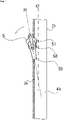
Fig. 8 shows a condition in the just oneseparate stringer 4b shown inFig. 4 where theslider 5 has stopped turning due to collision between the left flange 55 (in particular, a rear end thereof) and thefastener element 3b after turning in a direction the connectingpillar 53 moves away from thefastener element 3b on the just oneseparate stringer 4b (in a counterclockwise direction when viewed from above (see an arrow inFig. 4 )). InFig. 8 , position and trajectory of the opposedtape side 26b is indicated by dash-dot lines. - In the present embodiment, the
opposed tape side 26b extending toward the flange 54 (alternatively theflange 55 if theflange 54 is not provided) forms an angle of less than or equal to 45° (e.g. 44°, 43°, 42°, 41°, 40°, ···(enumeration of intermediate values is omitted)···, 15°) with respect to the center line X5 of the slider 5 (See θ4). Additionally or alternatively, in some cases, theside surface 56b of therear end 56e of theelongated protrusion 56 forms an angle of greater than or equal to 45° (e.g. 46°, 47°, 48°, 49°, 50°, ···(enumeration of intermediate values is omitted)···, 75°) with respect to the center line X5 of the slider 5 (See θ2). In some cases, θ2 is set to be 90°. In those cases, theslider 5 may be suitably adapted to a situation where it moves in the just oneseparate stringer 4b along thefastener element 3b. For example, as theslider 5 is turned and pulled rearward relative to the just oneseparate stringer 4b as described above, it is suppressed that thefastener tape 2b rides onto the elongated protrusion 56 (i.e. thestack 9b enters a space between theelongated protrusion 56 and the bottom wing 52) and that the rearward motion of theslider 5 is prevented or hindered. Similar to theside surface 56b, theside surface 56a of therear end 56e of theelongated protrusion 56 may form an angle of greater than or equal to 45° relative to the center line X5 of theslider 5, but should not be limited to this. Note that, as theslider 5 is turned and pulled rearward relative to the just oneseparate stringer 4b as described above, theside surface 56b of therear end 56e of theelongated protrusion 56 slides on theopposed tape side 26b of thefastener tape 2b of the just oneseparate stringer 4b. - Usually, by forming the
elongated protrusion 56 longer rearward, thefastener tapes pillar 53 in advance, facilitating stable decoupling and coupling of thefastener stringers elongated protrusion 56 longer rearward, the length of theelongated protrusion 56 is set to be shorter. In particular, theelongated protrusion 56 has a length d1 such that thestack 9b does not enter a space between theelongated protrusion 56 and thebottom wing 52 as, in the just oneseparate fastener stringer 4b of the pair offastener stringers slider 5 is pulled rearward while having been turned in a direction the connectingpillar 53 moves away from thefastener element 3b provided in the just oneseparate fastener stringer 4b. Accordingly, it is suppressed that thefastener tape 2b rides onto the elongated protrusion 56 (i.e. thestack 9b enters a space between theelongated protrusion 56 and the bottom wing 52) and that the rearward motion of theslider 5 is prevented or hindered. In cases where theelongated protrusion 56 extends rearward from the connectingpillar 53, the length d1 of theelongated protrusion 56 is equal to a (maximum) distance of the rear end of theelongated protrusion 56 from the connectingpillar 53 and. - In some cases, d1 /d2 ≦ 0.7 is satisfied in which d1 denotes a length of the
elongated protrusion 56, and d2 denotes a distance of a rear end of theslider 5 from the connectingpillar 53. In some instances, d1 /d2 ≦ 0.65 or d1 /d2 ≦ 0.6 is satisfied. It is envisaged that, by shortening theelongated protrusion 56, the condition of the angle between theopposed tape side 26b and the center line X5 of theslider 5 would be more easily satisfied. - In embodiments where a
pawl aperture 51n is formed at theelongated protrusion 56 of theslider 5, if thefastener tape 2b rides onto the elongated protrusion 56 (i.e. thestack 9b enters a space between theelongated protrusion 56 and the bottom wing 52), thefastener tape 2b may possibly be pressed into thepawl aperture 51n and thetape surface 21 of thefastener tape 2b may be scraped and damaged. Such disadvantage may be avoided or suppressed by satisfying the condition of the angle between theopposed tape side 26b and the center line X5 of theslider 5. - Description will follow referring to
Fig. 9 for a clearer understanding of the above-described feature.Fig. 9 is prepared with reference toFig. 2 of the patent literature 1. Similar toFig. 8 ,Fig. 9 shows a condition in the just oneseparate stringer 4b where theslider 5 has stopped turning due to collision between the flange 55 (in particular, a rear end thereof) and thefastener element 3b after turning in a direction the connectingpillar 53 moves away from thefastener element 3b on the just oneseparate stringer 4b (see an arrow inFig. 4 ). - In a case of
Fig. 9 , theopposed tape side 26b extending toward the flange 54 (alternatively theflange 55 if theflange 54 is not provided) forms an angle of greater than 45° with respect to the center line X5 of the slider 5 (See θ4'). Similarly, theside surface 56b of therear end 56e of theelongated protrusion 56 forms an angle of less than 45° with respect to the center line X5 of the slider 5 (See θ2'). In such a case, as theslider 5 is turned and pulled rearward relative to the just oneseparate stringer 4b as described above, thefastener tape 2b may possibly ride onto the elongated protrusion 56 (i.e. thestack 9b may possibly enter a space between theelongated protrusion 56 and the bottom wing 52) and the rearward motion of theslider 5 may be prevented or hindered. - The
slider 5 may be one with automatic stop function. In this instance, theslider 5 includes a lockingpawl 60 with apawl end 60t capable of projecting into a passage for fastener elements in theslider 5 through apawl aperture 51n formed at the top wing 51 (e.g. at the elongated protrusion 56). The lockingpawl 60 may be arranged to be elastically displaceable between a locking position (locking posture) and an unlocking position (unlocking posture) in accordance with operation of thepull tab 59. For example, as illustrated inFig. 10 , a lockingpawl 60, aleaf spring 61 for urging the lockingpawl 60, and acap 62 for accommodating these parts are provided. The lockingpawl 60 has apawl end 60t capable of projecting into the passage for fastener elements from apawl aperture 51n. Thepull tab 59 has anoperating rod 59k that moves the lockingpawl 60 to the unlocking position where thepawl end 60t does not project from thepawl aperture 51n, thus it is unlocked. When thepull tab 59 is released from one's hand, the lockingpawl 60 is urged by theleaf spring 61 to return to the locking position. Various types are known for the lockingpawl 60, and should not be limited to the illustrated examples. For example, in another case, the lockingpawl 60 is formed by bending a leaf spring, and is secured to thetop wing 51 such that thepawl end 60t of the lockingpawl 60 projects from thepawl aperture 51n. -
Fig. 11 illustrates an instance where thefastener tape fastener tape tape base fabric 2m and a water-resistant layer 2n formed on thetape base fabric 2m. Thetape base fabric 2m includes a woven structure or knitted structure or mixture thereof. The water-resistant layer 2n is a resin layer (e.g. a transparent resin layer) formed onto thetape base fabric 2m through coating or laminating. The water-resistant layer 2n is a resin layer such as made of polyurethane, and having a lower softness than that of thetape base fabric 2m. - In an embodiments where the
pawl aperture 51n is formed at theelongated protrusion 56 of theslider 5, if thefastener tape 2b rides onto the elongated protrusion 56 (i.e. thestack 9b enters a space between theelongated protrusion 56 and the bottom wing 52), thefastener tape 2b may possibly be pressed into thepawl aperture 51n and thetape surface 21 of thefastener tape 2b may be scraped and damaged. If thefastener tape resistant layer 2n, the water-resistant layer 2n may be scraped and damaged, and the commercial value of the slide fastener 1 and cloths with the slide fastener 1 would be deteriorated. Such outcome may be avoided or suppressed by satisfying the condition of the angle between theopposed tape side 26b and the center line X5 of theslider 5 as described above. - Based on the above teachings, a skilled person in the art would be able to add various modifications to the respective embodiments. Reference numerals in Claims are just for reference and should not be referred for the purpose of narrowly construing the scope of claims.
-
- 2a,2b
- Fastener tape
- 3a,3b
- Fastener element
- 4a,4b
- Fastener stringer
- 5
- Slider
- 51
- Top wing
- 52
- Bottom wing
- 53
- Connecting pillar
- 56
- Elongated protrusion
- 56e
- Rear end
- 56a,56b
- Side surfaces
Claims (12)
- A slide fastener (1) comprising:a pair of fastener stringers (4a,4b) each of which including a fastener tape (2a,2b) and a fastener element (3a,3b) arranged along one side-edge of the fastener tape (2a,2b); anda slider (5) that moves forward to couple the pair of fastener stringers (4a,4b) and moves rearward to decouple the pair of fastener stringers (4a,4b), the slider (5) including a top wing (51), a bottom wing (52), a connecting pillar (53) connecting said wings (51,52), and a flange (54,55) arranged at the top wing (51) or the bottom wing (52), whereinthe top wing (51) is provided with an elongated protrusion (56) extending rearward so as to be interposed between opposed tape sides (26a,26b) of the pair of fastener tapes (2a,2b) and,in just one separate fastener stringer (4b) of the pair of fastener stringers (4a,4b), when the slider (5) stops turning due to collision between the flange (54,55) and the fastener element (3b) after turning in a direction the connecting pillar (53) moves away from the fastener element (3b) provided in said just one separate fastener stringer (4b), the opposed tape side (26b) extending toward the flange (54,55) forms an angle of less than or equal to 45° with respect to a center line (X5) of the slider (5).
- The slide fastener according to claim 1, wherein the elongated protrusion (56) has a rear end (56e) tapered to be narrower in width rearward, and an angle between a side surface (56b) of the rear end (56e) and the center line (X5) of the slider (5) is greater than or equal to 45°.
- The slide fastener according to claim 1 or 2, wherein d1 /d2 ≦ 0.7 is satisfied in whichd1 denotes a length of the elongated protrusion (56), andd2 denotes a distance of a rear end of the slider (5) from the connecting pillar (53).
- The slide fastener according to any one of claims 1-3, wherein in said just one separate fastener stringer (4b), as the slider (5) is pulled rearward while the slider (5) stops turning as defined in Claim 1, a side surface (56b) of a rear end (56e) of the elongated protrusion (56) slides on the opposed tape side (26b) of the fastener tape (2b) of said just one separate fastener stringer (4b).
- The slide fastener according to any one of claims 1-4, wherein the bottom wing (52) has a partition (52j) extending rearward from the connecting pillar (53) in a manner to face at least partially the elongated protrusion (56).
- The slide fastener according to any one of claims 1-5, wherein the fastener tape (2a,2b) has a tape base fabric (2m) and a water-resistant layer (2n) formed on the tape base fabric (2m), and
the slider (5) includes a locking pawl (60) with a pawl end (60t) capable of projecting into a passage for fastener elements in the slider (5) through a pawl aperture (51n) formed at the elongated protrusion (56). - A slide fastener (1) comprising:a pair of fastener stringers (4a,4b) each of which including a fastener tape (2a,2b) and a fastener element (3a,3b) arranged along one side-edge of the fastener tape (2a,2b); anda slider (5) that moves forward to couple the pair of fastener stringers (4a,4b) and moves rearward to decouple the pair of fastener stringers (4a,4b), the slider (5) including a top wing (51), a bottom wing (52), a connecting pillar (53) coupling said wings (51,52), and a flange (54,55) arranged at the top wing (51) or the bottom wing (52), a stack (9a,9b) including the fastener tape (2a,2b) and the fastener element (3a,3b) being interposed between the top wing (51) and the bottom wing (52), a top surface (21) of the fastener tape (2a,2b) being contactable with the top wing (51), and the fastener element (3a,3b) arranged on a bottom surface (22) of the fastener tape (2a,2b) being contactable with the bottom wing (52), whereinthe top wing (51) is provided with an elongated protrusion (56) extending rearward so as to be interposed between opposed tape sides (26a,26b) of the pair of fastener tapes (2a,2b), andthe elongated protrusion (56) has a length (di) such that the stack (9b) does not enter a space between the elongated protrusion (56) and the bottom wing (52) when, in just one separate fastener stringer (4b) of the pair of fastener stringers (4a,4b), the slider (5) is pulled rearward while having been turned in a direction the connecting pillar (53) moves away from the fastener element (3b) provided in said just one separate fastener stringer (4b).
- The slide fastener according to claim 7, wherein d1 /d2 ≦ 0.7 is satisfied in whichd1 denotes the length of the elongated protrusion (56), andd2 denotes a distance of a rear end of the slider (5) from the connecting pillar (53) and.
- The slide fastener according to claim 7 or 8, wherein the elongated protrusion (56) has a rear end (56e) tapered to be narrower in width rearward, and an angle between a side surface (56b) of the rear end (56e) and a center line (X5) of the slider (5) is greater than or equal to 45°.
- The slide fastener according to any one of claims 7-9, wherein the slider (5) has been turned so that the flange (54,55) of the slider (5) is in contact with the fastener element (3a,3b) of said just one separate fastener stringer (4a,4b).
- A slider (5) for slide fastener, the slider comprising:a top wing (51);a bottom wing (52); anda connecting pillar (53) coupling said wings (51,52), whereinthe top wing (51) is provided with an elongated protrusion (56) extending rearward so as to be interposed between opposed tape sides (26a,26b) of a pair of fastener tapes (2a,2b) to be separated or adjoined by said slider (5),d1 f d2 ≦ 0.7 is satisfied in whichd1 denotes a length of the elongated protrusion (56), andd2 denotes a distance of a rear end of the slider (5) from the connecting pillar (53), andthe elongated protrusion (56) has a rear end (56e) tapered to be narrower in width rearward, an angle between a side surface (56b) of the rear end (56e) and a center line (X5) of the slider (5) being greater than or equal to 45°.
- The slider according to Claim 11, wherein the slider (5) has a locking pawl (60) with a pawl end (60t) capable of projecting into a passage for fastener elements in the slider (5) through a pawl aperture (51n) formed at the elongated protrusion (56).
Applications Claiming Priority (1)
| Application Number | Priority Date | Filing Date | Title |
|---|---|---|---|
| PCT/JP2020/010922 WO2021181632A1 (en) | 2020-03-12 | 2020-03-12 | Slider and slide fastener |
Publications (2)
| Publication Number | Publication Date |
|---|---|
| EP4118995A1 true EP4118995A1 (en) | 2023-01-18 |
| EP4118995A4 EP4118995A4 (en) | 2023-04-12 |
Family
ID=77670569
Family Applications (1)
| Application Number | Title | Priority Date | Filing Date |
|---|---|---|---|
| EP20924634.7A Pending EP4118995A4 (en) | 2020-03-12 | 2020-03-12 | SLIDE AND SLIDE CLOSURE |
Country Status (5)
| Country | Link |
|---|---|
| US (1) | US11839272B2 (en) |
| EP (1) | EP4118995A4 (en) |
| JP (1) | JP7759313B2 (en) |
| CN (1) | CN115175585B (en) |
| WO (1) | WO2021181632A1 (en) |
Families Citing this family (3)
| Publication number | Priority date | Publication date | Assignee | Title |
|---|---|---|---|---|
| WO2024069666A1 (en) * | 2022-09-26 | 2024-04-04 | Ykk株式会社 | Slider for slide fastener, and slide fastener |
| JPWO2025134338A1 (en) * | 2023-12-21 | 2025-06-26 | ||
| JP1798585S (en) | 2024-05-31 | 2025-05-15 | Slider for slide fastener |
Family Cites Families (8)
| Publication number | Priority date | Publication date | Assignee | Title |
|---|---|---|---|---|
| JP3379004B2 (en) | 1995-07-31 | 2003-02-17 | ワイケイケイ株式会社 | Slider for slide fastener with stop device |
| JPH10327911A (en) * | 1997-05-30 | 1998-12-15 | Ykk Corp | Slider for slide fastener with stop device |
| JP2000262309A (en) | 1999-03-17 | 2000-09-26 | Ykk Corp | Slide fastener slider |
| JP3618288B2 (en) * | 2000-09-29 | 2005-02-09 | Ykk株式会社 | Slider for filament slide fastener |
| JP3659325B2 (en) * | 2000-10-31 | 2005-06-15 | Ykk株式会社 | Airtight / watertight slide fastener slider |
| JP4072951B2 (en) | 2003-02-07 | 2008-04-09 | Ykk株式会社 | Slide fastener |
| KR101372717B1 (en) * | 2008-12-22 | 2014-03-11 | 컬럼비아 스포츠웨어 노스 아메리카, 인크. | Weather resistant slide fasteners |
| WO2019116514A1 (en) * | 2017-12-14 | 2019-06-20 | Ykk株式会社 | Slide fastener |
-
2020
- 2020-03-12 CN CN202080094367.8A patent/CN115175585B/en active Active
- 2020-03-12 EP EP20924634.7A patent/EP4118995A4/en active Pending
- 2020-03-12 US US17/910,691 patent/US11839272B2/en active Active
- 2020-03-12 WO PCT/JP2020/010922 patent/WO2021181632A1/en not_active Ceased
- 2020-03-12 JP JP2022505667A patent/JP7759313B2/en active Active
Also Published As
| Publication number | Publication date |
|---|---|
| EP4118995A4 (en) | 2023-04-12 |
| US20230146827A1 (en) | 2023-05-11 |
| JPWO2021181632A1 (en) | 2021-09-16 |
| US11839272B2 (en) | 2023-12-12 |
| CN115175585A (en) | 2022-10-11 |
| WO2021181632A1 (en) | 2021-09-16 |
| JP7759313B2 (en) | 2025-10-23 |
| CN115175585B (en) | 2025-09-23 |
Similar Documents
| Publication | Publication Date | Title |
|---|---|---|
| US11839272B2 (en) | Slider and slide fastener | |
| US9038249B2 (en) | Slider for concealed slide fastener | |
| EP1913833B1 (en) | Reverse opening type separable end stop of slide fastener | |
| EP2027789B1 (en) | Slider for concealed type slide fastener with separable bottom end stop | |
| CN110169624B (en) | Zipper stringer, zipper and zipper stringer installation structure | |
| KR100983163B1 (en) | Upper fixing part for slide fastener | |
| US9480311B2 (en) | Slide fastener with simple locking mechanism | |
| JP7758876B2 (en) | Slide fastener | |
| EP1920672A2 (en) | Fastener stringer of concealed type slide fastener | |
| US11839271B2 (en) | Slide fastener | |
| US20150113771A1 (en) | Slider for Slide Fastener | |
| CN222982584U (en) | Slider for slide fastener | |
| US20240090628A1 (en) | Slide fastener | |
| WO2013051127A1 (en) | Woven fastener stringer and slide fastener | |
| EP4684685A1 (en) | Slide fastener and method for manufacturing slide fastener | |
| CN121312922A (en) | zipper | |
| WO2026028263A1 (en) | Slider and slide fastener including same | |
| HK1125275A1 (en) | Slider for slide fastener | |
| HK1117353B (en) | Slider fastener having a reverse opening type separable end stop | |
| WO2025203404A1 (en) | Slide fastener |
Legal Events
| Date | Code | Title | Description |
|---|---|---|---|
| STAA | Information on the status of an ep patent application or granted ep patent |
Free format text: STATUS: THE INTERNATIONAL PUBLICATION HAS BEEN MADE |
|
| PUAI | Public reference made under article 153(3) epc to a published international application that has entered the european phase |
Free format text: ORIGINAL CODE: 0009012 |
|
| STAA | Information on the status of an ep patent application or granted ep patent |
Free format text: STATUS: REQUEST FOR EXAMINATION WAS MADE |
|
| 17P | Request for examination filed |
Effective date: 20220909 |
|
| AK | Designated contracting states |
Kind code of ref document: A1 Designated state(s): AL AT BE BG CH CY CZ DE DK EE ES FI FR GB GR HR HU IE IS IT LI LT LU LV MC MK MT NL NO PL PT RO RS SE SI SK SM TR |
|
| A4 | Supplementary search report drawn up and despatched |
Effective date: 20230313 |
|
| RIC1 | Information provided on ipc code assigned before grant |
Ipc: A44B 19/30 20060101ALI20230306BHEP Ipc: A44B 19/24 20060101ALI20230306BHEP Ipc: A44B 99/00 20100101ALI20230306BHEP Ipc: B65D 33/25 20060101ALI20230306BHEP Ipc: A44B 19/26 20060101AFI20230306BHEP |
|
| DAV | Request for validation of the european patent (deleted) | ||
| DAX | Request for extension of the european patent (deleted) | ||
| STAA | Information on the status of an ep patent application or granted ep patent |
Free format text: STATUS: EXAMINATION IS IN PROGRESS |
|
| 17Q | First examination report despatched |
Effective date: 20250103 |