EP4117406A1 - Fan assembly, power supply apparatus, and manufacturing method for power supply apparatus - Google Patents
Fan assembly, power supply apparatus, and manufacturing method for power supply apparatus Download PDFInfo
- Publication number
- EP4117406A1 EP4117406A1 EP21933484.4A EP21933484A EP4117406A1 EP 4117406 A1 EP4117406 A1 EP 4117406A1 EP 21933484 A EP21933484 A EP 21933484A EP 4117406 A1 EP4117406 A1 EP 4117406A1
- Authority
- EP
- European Patent Office
- Prior art keywords
- mounting member
- opening
- connecting sleeve
- flexible connecting
- mounting
- Prior art date
- Legal status (The legal status is an assumption and is not a legal conclusion. Google has not performed a legal analysis and makes no representation as to the accuracy of the status listed.)
- Pending
Links
Images




Classifications
-
- H—ELECTRICITY
- H01—ELECTRIC ELEMENTS
- H01M—PROCESSES OR MEANS, e.g. BATTERIES, FOR THE DIRECT CONVERSION OF CHEMICAL ENERGY INTO ELECTRICAL ENERGY
- H01M10/00—Secondary cells; Manufacture thereof
- H01M10/60—Heating or cooling; Temperature control
- H01M10/65—Means for temperature control structurally associated with the cells
- H01M10/656—Means for temperature control structurally associated with the cells characterised by the type of heat-exchange fluid
- H01M10/6561—Gases
- H01M10/6563—Gases with forced flow, e.g. by blowers
-
- F—MECHANICAL ENGINEERING; LIGHTING; HEATING; WEAPONS; BLASTING
- F04—POSITIVE - DISPLACEMENT MACHINES FOR LIQUIDS; PUMPS FOR LIQUIDS OR ELASTIC FLUIDS
- F04D—NON-POSITIVE-DISPLACEMENT PUMPS
- F04D25/00—Pumping installations or systems
- F04D25/16—Combinations of two or more pumps ; Producing two or more separate gas flows
- F04D25/166—Combinations of two or more pumps ; Producing two or more separate gas flows using fans
-
- F—MECHANICAL ENGINEERING; LIGHTING; HEATING; WEAPONS; BLASTING
- F04—POSITIVE - DISPLACEMENT MACHINES FOR LIQUIDS; PUMPS FOR LIQUIDS OR ELASTIC FLUIDS
- F04D—NON-POSITIVE-DISPLACEMENT PUMPS
- F04D19/00—Axial-flow pumps
- F04D19/002—Axial flow fans
-
- F—MECHANICAL ENGINEERING; LIGHTING; HEATING; WEAPONS; BLASTING
- F04—POSITIVE - DISPLACEMENT MACHINES FOR LIQUIDS; PUMPS FOR LIQUIDS OR ELASTIC FLUIDS
- F04D—NON-POSITIVE-DISPLACEMENT PUMPS
- F04D29/00—Details, component parts, or accessories
- F04D29/02—Selection of particular materials
- F04D29/023—Selection of particular materials especially adapted for elastic fluid pumps
-
- F—MECHANICAL ENGINEERING; LIGHTING; HEATING; WEAPONS; BLASTING
- F04—POSITIVE - DISPLACEMENT MACHINES FOR LIQUIDS; PUMPS FOR LIQUIDS OR ELASTIC FLUIDS
- F04D—NON-POSITIVE-DISPLACEMENT PUMPS
- F04D29/00—Details, component parts, or accessories
- F04D29/40—Casings; Connections of working fluid
- F04D29/52—Casings; Connections of working fluid for axial pumps
- F04D29/522—Casings; Connections of working fluid for axial pumps especially adapted for elastic fluid pumps
-
- F—MECHANICAL ENGINEERING; LIGHTING; HEATING; WEAPONS; BLASTING
- F04—POSITIVE - DISPLACEMENT MACHINES FOR LIQUIDS; PUMPS FOR LIQUIDS OR ELASTIC FLUIDS
- F04D—NON-POSITIVE-DISPLACEMENT PUMPS
- F04D29/00—Details, component parts, or accessories
- F04D29/60—Mounting; Assembling; Disassembling
- F04D29/601—Mounting; Assembling; Disassembling specially adapted for elastic fluid pumps
-
- H—ELECTRICITY
- H01—ELECTRIC ELEMENTS
- H01M—PROCESSES OR MEANS, e.g. BATTERIES, FOR THE DIRECT CONVERSION OF CHEMICAL ENERGY INTO ELECTRICAL ENERGY
- H01M10/00—Secondary cells; Manufacture thereof
- H01M10/60—Heating or cooling; Temperature control
- H01M10/61—Types of temperature control
- H01M10/613—Cooling or keeping cold
-
- H—ELECTRICITY
- H05—ELECTRIC TECHNIQUES NOT OTHERWISE PROVIDED FOR
- H05K—PRINTED CIRCUITS; CASINGS OR CONSTRUCTIONAL DETAILS OF ELECTRIC APPARATUS; MANUFACTURE OF ASSEMBLAGES OF ELECTRICAL COMPONENTS
- H05K7/00—Constructional details common to different types of electric apparatus
- H05K7/20—Modifications to facilitate cooling, ventilating, or heating
- H05K7/20009—Modifications to facilitate cooling, ventilating, or heating using a gaseous coolant in electronic enclosures
- H05K7/20136—Forced ventilation, e.g. by fans
- H05K7/20145—Means for directing air flow, e.g. ducts, deflectors, plenum or guides
-
- H—ELECTRICITY
- H05—ELECTRIC TECHNIQUES NOT OTHERWISE PROVIDED FOR
- H05K—PRINTED CIRCUITS; CASINGS OR CONSTRUCTIONAL DETAILS OF ELECTRIC APPARATUS; MANUFACTURE OF ASSEMBLAGES OF ELECTRICAL COMPONENTS
- H05K7/00—Constructional details common to different types of electric apparatus
- H05K7/20—Modifications to facilitate cooling, ventilating, or heating
- H05K7/20009—Modifications to facilitate cooling, ventilating, or heating using a gaseous coolant in electronic enclosures
- H05K7/20136—Forced ventilation, e.g. by fans
- H05K7/20172—Fan mounting or fan specifications
-
- Y—GENERAL TAGGING OF NEW TECHNOLOGICAL DEVELOPMENTS; GENERAL TAGGING OF CROSS-SECTIONAL TECHNOLOGIES SPANNING OVER SEVERAL SECTIONS OF THE IPC; TECHNICAL SUBJECTS COVERED BY FORMER USPC CROSS-REFERENCE ART COLLECTIONS [XRACs] AND DIGESTS
- Y02—TECHNOLOGIES OR APPLICATIONS FOR MITIGATION OR ADAPTATION AGAINST CLIMATE CHANGE
- Y02E—REDUCTION OF GREENHOUSE GAS [GHG] EMISSIONS, RELATED TO ENERGY GENERATION, TRANSMISSION OR DISTRIBUTION
- Y02E60/00—Enabling technologies; Technologies with a potential or indirect contribution to GHG emissions mitigation
- Y02E60/10—Energy storage using batteries
Definitions
- the present application relates to the technical field of battery cooling, and in particular, to a fan assembly, a power supply device, and a method for manufacturing a power supply device.
- the heat generation element is arranged within an element compartment.
- the heat generation element generates heat during operation, and the heat generated by the heat generation element needs to be dissipated from the element compartment to ensure that the heat generation element runs within a preset operating temperature range.
- the engineering device further includes an air duct in which cold air is transported, and a fan assembly brings the air duct into communication with the element compartment, so as to promote entry of the cold air into the element compartment from the air duct, and take away the heat generated by the heat generation element during the operation by means of the cold air.
- the present application provides a fan assembly, which is connected between an element compartment and an air duct, can adapt to a mounting error, connects the element compartment to the air duct in a sealed manner, and has a good tolerance.
- the present application further provides a power supply device and a method for manufacturing a power supply device, wherein a fan assembly is connected between a battery storage apparatus and an air duct, can adapt to a mounting error, connects the battery storage apparatus to the air duct in a sealed manner, and has a good tolerance.
- An embodiment of the present application provides a fan assembly, comprising: a first mounting member provided with a first opening; a second mounting member provided with a second opening; a flexible connecting sleeve having a first end connected to the first mounting member and a second end connected to the second mounting member, the flexible connecting sleeve being configured to communicate the first opening with the second opening; and a fan, which is arranged within the flexible connecting sleeve and is configured to promote flow of gas from the first opening to the second opening.
- the fan assembly is mounted between the air duct and the element compartment.
- the flexible connecting sleeve can adapt to the deviation of the relative position of the first opening and the second opening through deformation, without affecting the sealing performance of the fan assembly, thereby avoiding an air volume loss caused by poor sealing.
- the fan assembly according to this embodiment of the present application further can have the following additional technical features.
- the fan assembly further comprises: a first fixing ring configured to fix the first end of the flexible connecting sleeve to the first mounting member, wherein the first end of the flexible connecting sleeve is fitted over the first mounting member, and the first fixing ring is fitted over the first end of the flexible connecting sleeve.
- the first fixing ring can be further fitted over the first end of the flexible connecting sleeve, so as to implement peripheral-side sealing of the first end of the flexible connecting sleeve, so that the first end of the flexible connecting sleeve is connected to the first mounting member in a peripheral-side sealed manner, so as to avoid air leakage caused by a slit at a joint between the first end of the flexible connecting sleeve and the first mounting member.
- the fan assembly further comprises: a first fixing member, wherein the first fixing ring is provided with a first mounting hole, the first end of the flexible connecting sleeve is provided with a second mounting hole, and the first fixing member is configured to pass through the first mounting hole and the second mounting hole and be connected to the first mounting member, so as to fix the first end of the flexible connecting sleeve to the first mounting member.
- This form is not only easy to assemble, but can also fix the first end of the flexible connecting sleeve to the first mounting member in a circumferentially sealed manner by means of the first fixing ring, so as to avoid air leakage during use caused by loosening of the first end of the flexible connecting sleeve.
- the fan assembly further comprises: a second fixing ring configured to fix the second end of the flexible connecting sleeve to the second mounting member, wherein the second end of the flexible connecting sleeve is fitted over the second mounting member, and the second fixing ring is fitted over the second end of the flexible connecting sleeve.
- the second fixing ring can be further fitted over the second end of the flexible connecting sleeve, so as to implement peripheral-side sealing of the second end of the flexible connecting sleeve, so that the second end of the flexible connecting sleeve is connected to the second mounting member in a peripheral-side sealed manner, so as to avoid air leakage caused by a slit at a joint between the second end of the flexible connecting sleeve and the second mounting member.
- the fan assembly further comprises: a second fixing member, wherein the second fixing ring is provided with a third mounting hole, the second end of the flexible connecting sleeve is provided with a fourth mounting hole, and the second fixing member is configured to pass through the third mounting hole and the fourth mounting hole and be connected to the second mounting member, so as to fix the second end of the flexible connecting sleeve to the second mounting member.
- This form is not only easy to assemble, but can also fix the second end of the flexible connecting sleeve to the second mounting member in a circumferentially sealed manner by means of the second fixing ring, so as to avoid air leakage during use caused by loosening of the second end of the flexible connecting sleeve.
- the first mounting member comprises a first base plate and a first connecting member
- the first base plate is provided with the first opening
- the first connecting member is arranged on the side of the first base plate facing the flexible connecting sleeve
- the first connecting member is arranged around the first opening
- the first end of the flexible connecting sleeve is fitted over the first connecting member
- an outer peripheral side of the first connecting member is attached to the first end of the flexible connecting sleeve, so that the first connecting member can be connected to the first end of the flexible connecting sleeve in a peripheral-side sealed manner; and the provision of the first base plate facilitates connection to the element compartment via the first base plate.
- the first mounting member comprises a first sub-base plate, a second sub-base plate, and a first connecting member
- the first opening is formed in the first connecting member
- the first sub-base plate and the second sub-base plate are symmetrically arranged with respect to the first connecting member
- the first end of the flexible connecting sleeve is fitted over the first connecting member
- first connecting member an outer peripheral side of the first connecting member is attached to the first end of the flexible connecting sleeve, so that the first connecting member can be connected to the first end of the flexible connecting sleeve in a peripheral-side sealed manner.
- the symmetrical arrangement of the first sub-base plate and the second sub-base plate with respect to the first connecting member facilitates connection to the element compartment via the first sub-base plate and the second sub-base plate and can further reduce the weight of the first mounting member.
- the second mounting member comprises a second base plate and a second connecting member
- the second base plate is provided with the second opening
- the second connecting member is arranged on the side of the second base plate facing the flexible connecting sleeve
- the second connecting member is arranged around the second opening
- the second end of the flexible connecting sleeve is fitted over the second connecting member
- an outer peripheral side of the second connecting member is attached to the second end of the flexible connecting sleeve, so that the second connecting member can be connected to the second end of the flexible connecting sleeve in a peripheral-side sealed manner.
- the provision of the second base plate facilitates connection to the element compartment via the second base plate.
- the fan is fixed to the side of the second base plate facing the flexible connecting sleeve, the second connecting member is arranged around the fan, and the second connecting member is provided with a wiring hole for allowing a wire harness of the fan to pass through.
- the second connecting member is provided with the wiring hole, the wire harness of the fan passes through the wiring hole, and an end portion of the wire harness is exposed to the exterior of the fan assembly and is connected to an external power supply and control unit.
- a layout design can be simplified when the wire harness of the fan is connected to the external power supply and control unit.
- the fan assembly further comprises: a cover plate, which is arranged opposite the second base plate, is fixed to the fan, and is configured to limit the wire harness of the fan between the cover plate and the second base plate.
- the fan is fixed to the second mounting member.
- the fixing of the fan to the second mounting member enables the fan to be as close as possible to the second opening, thereby increasing an air speed at the second opening of the fan assembly.
- Increasing the air discharge speed of the fan assembly can improve the air discharge efficiency of the fan assembly, promote blowing of cold air into the interior of the element compartment, and increase an effective cooling area, so as to fully cool a heat generation element.
- the wire harness is limited between the cover plate and the second base plate, which can prevent the wire harness from being drawn into the fan.
- the flexible connecting sleeve is made of a fabric or resin material, is soft in texture, can flexibly deform, has a good wear resistance, is thick and windproof, and can prevent cold air from seeping through the flexible connecting sleeve.
- An embodiment of the present application further provides a power supply device, comprising: a case; a battery storage apparatus, configured to store a battery, mounted within the case and provided with an air inlet; an air duct mounted within the case and provided with an air outlet; and a fan assembly mentioned above, wherein the first mounting member is mounted to the air duct to bring the first opening into communication with the air outlet, and the second mounting member is mounted to the battery storage apparatus to bring the second opening into communication with the air inlet.
- the foregoing fan assembly is used to connect the air outlet of the air duct to the air inlet of the battery storage apparatus, and can adapt to a deviation of relative position of the air inlet and the air outlet caused by a mounting error when the air duct and the battery storage apparatus are assembled within the case, thereby avoiding air leakage and ensuring a good heat dissipation consistency of the battery storage apparatus in the power supply device.
- the air duct comprises an air duct body and a guide assembly
- the air outlet is arranged on the air duct body
- the guide assembly is fixed to the air duct body
- the guide assembly is configured to guide the first mounting member to slide in an extension direction of the guide assembly, such that the air outlet is in communication with the first opening.
- the provision of the guide assembly in the air duct body can guide the first mounting member to slide along the extension direction of the guide assembly, thereby ensuring relative position of the first mounting member and the air duct, facilitating communication between the air outlet and the first opening, and ensuring sealed connection between the fan assembly and the air duct.
- the power supply device further comprises: a third fixing member, wherein the first mounting member is provided with a fifth mounting hole, the air duct is provided with a sixth mounting hole, and the third fixing member is configured to pass through the fifth mounting hole and be connected to the sixth mounting hole, so as to fix the first mounting member to the air duct; and the air duct further comprises a fitting portion, the first mounting member further comprises a limiting portion, the limiting portion is configured to abut against the fitting portion to limit sliding of the first mounting member along the guide assembly, and the limiting portion is configured to align the fifth mounting hole with the sixth mounting hole when the limiting portion abuts against the fitting portion.
- the abutment between the limiting portion and the fitting portion can locate the position of the first mounting member relative to the air duct, and facilitate connection between the first mounting member and the air duct via the first mounting member by a worker, so as to improve the peripheral-side sealing performance between the first mounting member and the air duct.
- the power supply device further comprises: a sealing member arranged between the second mounting member and the battery storage apparatus and surrounding the air inlet, to implement sealed connection between the second mounting member and the battery storage apparatus.
- the sealing member can seal a peripheral side of the second opening, and prevent the loss of cold caused by lateral leakage of cold air from a slit between the second mounting member and the battery storage apparatus, thereby ensuring the heat dissipation consistency of the battery storage apparatus.
- An embodiment of the present application further provides a method for manufacturing a power supply device, the method comprising:
- the deformation of the flexible connecting sleeve can adapt to a change in the relative position of the first mounting member and the second mounting member, so that the peripheral-side sealing performance of the air inlet and the air outlet can be kept even if there is a mounting error between the battery storage apparatus and the air duct, thereby not only avoiding the air volume loss caused by air leakage, but also ensuring the heat dissipation consistency of the battery storage apparatus in the power supply device.
- an engineering device comprises an element compartment, an air duct, and an air cooling apparatus.
- a heat generation element is arranged within the element compartment, and generates heat during operation.
- the air duct comprises a cold air inlet and an air outlet, the cold air inlet is connected to the air cooling apparatus, and the air outlet is connected to the element compartment by means of a conventional fan assembly.
- the air cooling apparatus feeds cold air into the air duct, the conventional fan assembly promotes entry of the cold air into the element compartment, and the cold air takes away the heat generated by the heat generation element during operation.
- the air inlet of the element compartment has an intake air volume smaller than a discharge air volume of the air outlet of the air duct, and the cold air is lost from joints between the fan assembly and the element compartment and the air duct, which not only leads to a loss of cold air, but also reduces the heat dissipation consistency of the element compartment.
- an embodiment of the present application provides a novel fan assembly, which is mounted between an air duct and an element compartment of an engineering device.
- the novel fan assembly can adapt to a deviation of relative position of an air outlet of the air duct and the element compartment, and therefore can still be in sealed connection with the air outlet and an air inlet even if there is a deviation of relative position of the air outlet and the air inlet, so that there is no air leakage at joints between the novel fan assembly and the element compartment and the air duct.
- the engineering device is a power supply device
- the heat generation element is a battery, which generates heat during operation.
- the engineering device may also be a large computer case, and the heat generation element may be a chip. Further, the engineering device may also comprise a thermostatic element, and hot air is sent out from the air duct. By supplying the hot air into the element compartment, the thermostatic element in the element compartment is kept operating at a high enough temperature.
- FIGS. 1 and 2 respectively show a schematic isometric view and a front schematic structural diagram of a partial structure of a power supply device 1 disclosed in an embodiment of the present application.
- the power supply device 1 comprises a case 10, a battery storage apparatus 20, an air duct 30, a fan assembly 40, and an air cooling apparatus 50.
- the battery storage apparatus 20 is configured to store a battery, and the battery storage apparatus 20 and the air duct 30 are mounted within the case 10.
- the battery storage apparatus 20 is provided with an air inlet 211, and the air duct 30 extends in a direction m.
- the air duct 30 comprises a cold air inlet 311 and an air outlet 312.
- the cold air inlet 311 is connected to the air cooling apparatus 50, and cold air output by the air cooling apparatus 50 enters the air duct 30 through the cold air inlet 311 and is transported in the direction m.
- the fan assembly 40 brings the air outlet 312 into communication with the air inlet 211, to introduce the cold air from the air duct 30 into the battery storage apparatus 20 in a direction n, so as to cool the battery stored in the battery storage apparatus 20.
- the directions m, q, and n are respectively length, width and height directions of the power supply device 1 disclosed in the embodiments of the present application.
- the air cooling apparatus 50 may be arranged inside the case to make efficient use of a space inside the case.
- the air cooling apparatus 50 is placed in the case with a limited volume, so that the power supply device 1 has a compact structure.
- the air cooling apparatus 50 is arranged outside the case, and the air duct 30 and the air cooling apparatus 50 are connected to each other outside the case.
- FIG. 1 shows a schematic isometric view of a partial structure of a power supply device 1 disclosed in an embodiment of the present application.
- a mounting frame 21 is arranged on the side of the battery storage apparatus 20 close to the air duct 30, the mounting frame 21 is provided with an air inlet 211 in communication with the interior of the battery storage apparatus 20, and the cold air enters the interior of the battery storage apparatus 20 from the air inlet 211 to cool the battery stored in the battery storage apparatus 20.
- the battery storage apparatus 20 is further provided with a ventilation opening 212, such that the cold air can enter the battery storage apparatus 20 to cool the battery, and then leave the battery storage apparatus 20 through the ventilation opening 212, so as to take away heat emitted by the battery during power supply.
- the ventilation opening 212 and the air inlet 211 may be respectively arranged at two opposite ends of the battery storage apparatus 20 in the direction n, such that the cold air is guided to enter the battery storage apparatus 20 in the direction n from the air inlet 211 and then continues to flow in the direction n, passes across a plurality of batteries and take away heat emitted by the batteries during power supply, so that cold carried by the cold air can be fully used, and a better cooling effect can be achieved with the same cold air volume.
- the ventilation opening 212 is arranged on a side wall of the battery storage apparatus 20, the battery storage apparatus 20 comprises a first end and a second end opposite to each other in the direction n, and the side wall refers to a wall body between the first end and the second end of the battery storage apparatus 20.
- FIG. 2 is a front schematic structural diagram of a partial structure of a power supply device 1 disclosed in an embodiment of the present application.
- the side of the air duct 30 close to the battery storage apparatus 20 is provided with an air outlet 312, and the air outlet 312 and the air inlet 211 are arranged opposite each other in the direction n.
- the fan assembly 40 is used to connect the air outlet 312 to the air inlet 211.
- the provision of the fan assembly 40 can promote entry of cold air from the air duct 30 into the battery storage apparatus 20 in the direction n, so as to cool the battery placed in the battery storage apparatus 20.
- FIGS. 3 and 4 respectively show front and bottom schematic structural diagrams of an air duct 30 of a power supply device 1 in an embodiment of the present application.
- the air duct 30 extends in the direction m and feeds air in the direction m, a plurality of air outlets 312 are provided, and the plurality of air outlets 312 are arranged at intervals in the direction m.
- the side of the battery storage apparatus 20 close to the air duct 30 is provided with a plurality of air inlets 211, and the air inlets 211 correspond to the air outlets 312 on a one-to-one basis.
- Each air outlet 312 is connected to the corresponding air inlet 211 by means of one fan assembly 40.
- Cold air in the air duct 30 enters, from each air outlet 312, the corresponding air inlet 211 in the direction n, and a plurality of streams of cold air jointly cool the batteries stored in the battery storage apparatus 20.
- the fan assembly 40 in this embodiment of the present application is connected between the air duct 30 and the battery storage apparatus 20.
- the fan assembly 40 can adapt to a deviation of relative position of the air outlet 312 of the air duct 30 and the air inlet 211 of the battery storage apparatus 20, and therefore can still be connected to the air outlet 312 and the air inlet 211 in a sealed manner even if there is a deviation of relative position of the air outlet 312 and the air inlet 211.
- FIG. 5 shows a top schematic structural diagram of a battery storage apparatus 20 in a power supply device 1 disclosed in an embodiment of the present application.
- the battery storage apparatus 20 stores a plurality of battery units 22 spaced apart each other in the direction m, and each battery unit 22 comprises a plurality of batteries.
- Each battery unit 22 is arranged between two adjacent air inlets 211, and each air inlet 211 is arranged between two adjacent battery units 22.
- cold air can be blown from two sides of each battery unit 22 to the battery unit 22, and each battery in the battery unit 22 can be cooled, thereby avoiding a phenomenon that a battery located on the side away from the air inlet 211 cannot be blown by the cold air due to mutual shielding of the batteries, and improving the heat dissipation uniformity of the battery storage apparatus 20.
- each air inlet 211 feeds a stream of cold air to cool the battery sufficiently and uniformly.
- FIGS. 6 and 7 respectively show top and bottom schematic structural diagrams of a fan assembly 40 disclosed in an embodiment of the present application.
- the fan assembly 40 comprises a first mounting member 41, a second mounting member 42, a flexible connecting sleeve 43, and a fan 44.
- Two ends of the flexible connecting sleeve 43 are respectively a first end 431 and a second end 432, the first end 431 is connected to the first mounting member 41, the second end 432 is connected to the second mounting member 42, and the fan 44 is arranged within the flexible connecting sleeve 43.
- the flexible connecting sleeve 43 is made of a deformable material, and can flexibly connect the first mounting member 41 to the second mounting member 42 by means of the first end 431 and the second end 432, so as to allow a relative position of the first mounting member 41 and the second mounting member 42 to change, thereby adapting to a position deviation of the air duct 30 and the battery storage apparatus 20 during assembly.
- the flexible connecting sleeve 43 is made of a fabric or resin material, is soft in texture, and can flexibly deform, so as to allow the relative position of the first mounting member 41 and the second mounting member 42 to change.
- this material has a high surface density, which can avoid the loss of cold caused by the seepage of cold air through the flexible connecting sleeve 43.
- the flexible connecting sleeve 43 may be a rubber sleeve, which can not only flexibly deform, but can also have a good elasticity, so as to further allow for a greater position deviation between the first mounting member 41 and the second mounting member 42 through tensile deformation.
- FIGS. 6 and 7 respectively show top and bottom schematic structural diagrams of a fan assembly disclosed in an embodiment of the present application.
- a first mounting member 41 is provided with a first opening 413
- a second mounting member 42 is provided with a second opening 423
- a flexible connecting sleeve 43 is configured to communicate the first opening 413 with the second opening 423.
- Gas enters the interior of the fan assembly 40 from the first opening 413 and leaves the fan assembly 40 from the second opening 423.
- the fan 44 promotes flow of the gas in the direction n inside the flexible connecting sleeve 43, so as to promote flow of the gas from the first opening 413 to the second opening 423.
- the flexible connecting sleeve 43 has a rectangular cross section (that is, a section perpendicular to the direction n), and the two fans 44 are arranged at intervals in a length direction of the rectangular air intake cross section, so as to uniformly promote flow of the gas in the flexible connecting sleeve 43.
- two second openings 423 are provided, and an air discharge side 444 of each fan 44 corresponds to one second opening 423.
- the number and arrangement of the fans 44 may be flexibly set according to the shape of an air intake/discharge cross section of the fan assembly 40, so as to promote uniform air discharge of the fan assembly 40.
- the fan assembly 40 has a square air intake/discharge cross section, four fans 44 are provided, and the four fans 44 are uniformly arranged inside the flexible connecting sleeve 43 in a square array and are located on the same plane parallel to the air intake/discharge cross section of the fan assembly 40.
- the fan assembly 40 has a circular air intake/discharge cross section, six fans 44 are provided, and the six fans 44 are uniformly arranged inside the flexible connecting sleeve 43 in an annular array and are located on the same plane parallel to the air intake/discharge cross section of the fan assembly 40.
- the air intake/discharge cross section of the fan assembly 40 is regularly polygonal or circular, one fan 44 is provided, and the fan 44 is centrally arranged inside the flexible connecting sleeve 43.
- the fan 44 is fixed to the second mounting member 42, so that the fan 44 can be as close as possible to the air inlet 211 of the battery storage apparatus 20 (referring to FIG. 5 ), thereby increasing the air speed at the air inlet 211, enabling cold air to blow into the battery storage apparatus 20, and increasing an effective cooling area to cool a larger number of batteries.
- the fan 44 is fixed to the first mounting member 41 to promote flow of an airflow near the first opening 413 in the direction n.
- the fan 44 is arranged in a region between the first mounting member 41 and the second mounting member 42 by means of an additional support, so as to promote gas flow in a balanced manner.
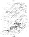
- FIG. 8 shows an exploded view of a fan assembly 40 disclosed in an embodiment of the present application. A specific structural form of the fan assembly 40 is illustrated in detail below.
- the fan assembly 40 comprises a first fixing ring 45 configured to fix a first end 431 of the flexible connecting sleeve 43 to a first mounting member 41.
- the first end 431 is fitted over the first mounting member 41, and the first fixing ring 45 is fitted over the first end 431.
- the first fixing ring 45 can be further fitted over the first end 431, so as to implement peripheral-side sealing of the first end 431, so that the first end 431 is connected to the first mounting member 41 in a peripheral-side sealed manner, so as to avoid air leakage caused by a slit at a joint between the first end 431 and the first mounting member 41.
- the first fixing ring 45 may be a rigid component, such as a plastic ring or a metal ring.
- the first fixing ring 45 and the first mounting member 41 jointly clamp the first end 431 to implement the peripheral-side sealing of the first end 431.
- the first end 431 of the flexible connecting sleeve 43 can also connect to the first mounting member 41 in another manner.
- an opening of the first end 431 of the flexible connecting sleeve 43 can be circumferentially expandable and is elastic. The opening of the first end 431 is expanded and then fitted over the first mounting member 41, and the opening of the first end 431 shrinks in a circumferential direction under its own elasticity and is tightly fitted over the first mounting member 41; or a circle of glue is applied to an inner edge of the first end 431, and the first end 431 is bonded to the first mounting member 41, etc.
- the fan assembly 40 can further comprise a first fixing member 481.
- the first fixing ring 45 is provided with a first mounting hole 451
- the first end 431 of the flexible connecting sleeve 43 is provided with a second mounting hole 4311
- the first fixing member 481 is configured to pass through the first mounting hole 451 and the second mounting hole 4311 and be connected to the first mounting member 41, so as to fix the first end 431 to the first mounting member 41.
- This form is not only easy to assemble, but can also fix the first end 431 of the flexible connecting sleeve 43 to the first mounting member 41 in a circumferentially sealed manner by means of the first fixing ring 45, so as to avoid air leakage caused by loosening of the first end 431 during use.
- the first fixing member 481 may be a screw, and the first mounting member 41 is provided with a threaded hole corresponding to the first mounting hole 451, so that the first fixing member 481 is in a threaded fit with the threaded hole.
- the first fixing member 481 may be a rivet for riveting the first fixing ring 45 to the first mounting member 41.
- first end 431 to the first mounting member 41 in a peripheral-side sealed manner by winding a steel wire, a fabric strip, a rubber band, etc.
- the first mounting member 41 comprises a first base plate 411 and a first connecting member 412
- the first base plate 411 is provided with the first opening 413
- the first connecting member 412 is arranged on the side of the first base plate 411 facing the flexible connecting sleeve 43
- the first connecting member 412 is arranged around the first opening 413
- the first end 431 of the flexible connecting sleeve 43 is fitted over the first connecting member 412.
- first base plate 411 two opposite sides of the first base plate 411 in the direction n are respectively a first side 4111 of the first base plate and a second side 4112 of the first base plate.
- the first connecting member 412 is mounted to the second side 4112 of the first base plate.
- the first opening 413 is a hole in the first mounting member 41.
- the first opening 413 is a hole penetrating the first base plate 411 in the direction n.
- the first connecting member 412 is arranged around the first opening 413.
- the first base plate 411 may be of an integrated structure or a spliced structure, and one or more first connecting members 412 surrounding the first opening 413 may be provided.
- the first connecting member 412 when one first connecting member 412 is provided, the first connecting member 412 may be configured as an annular structure and arranged around the first opening 413. In another example, when a plurality of first connecting members 412 are provided, the first connecting members 412 may be arranged at intervals around the first opening 413.
- an outer peripheral side of the first connecting member 412 is circumferentially attached to the first end 431 of the flexible connecting sleeve 43, and the first fixing ring 45 and the first connecting member 412 jointly clamp the first end 431 to implement the peripheral-side sealing of the first end 431; and the provision of the first base plate 411 enables the first mounting member 41 to have a sufficient area for assembly with other components.
- FIG. 9 shows a schematic structural diagram of a first mounting member 41 in another form in a fan assembly 40 disclosed in an embodiment of the present application, and illustrates a specific structural form of the first mounting member 41 in another form.
- a first opening 413 is a hole formed in a first connecting member 412.
- the first mounting member 41 comprises a first sub-base plate 415, a second sub-base plate 416, and a first connecting member 412.
- the first opening 413 is formed in the first connecting member 412, and the first sub-base plate 415 and the second sub-base plate 416 are symmetrically arranged with respect to the first connecting member 412.
- the symmetrical arrangement of the first sub-base plate 415 and the second sub-base plate 416 with respect to the first connecting member 412 not only provides a sufficient mounting area for the first mounting member 41, but can also reduce the weight of the first mounting member 41, thereby reducing the total weight of the fan assembly 40 and facilitating the mounting of the fan assembly 40.
- the first mounting members 41 may comprise three or four sub-base plates, and the four sub-base plates are arranged around the first opening 413 of the first connecting member 412.
- the first mounting member 41 may be in another form, and for example, may be of a sleeve structure or a plate-like structure with a hole, which can also be connected to the first end 431 of the flexible connecting sleeve 43, and bring the first opening 413 into communication with the flexible connecting sleeve 43.
- the fan assembly 40 further comprises a second fixing ring 46 configured to fix a second end 432 of the flexible connecting sleeve 43 to the second mounting member 42.
- the second end 432 of the flexible connecting sleeve 43 is fitted over the second mounting member 42, and the second fixing ring 46 is fitted over the second end 432 of the flexible connecting sleeve 43.
- the second fixing ring 46 may be a rigid component, such as a plastic ring or a metal ring.
- the second fixing ring 46 and the second mounting member 42 jointly clamp the second end 432 to implement the peripheral-side sealing of the second end 432.
- the second end 432 of the flexible connecting sleeve 43 is also to connect the second end 432 of the flexible connecting sleeve 43 to the second mounting member 42 in another manner.
- an opening of the second end 432 of the flexible connecting sleeve 43 is circumferentially expandable and is elastic.
- the opening of the second end 432 is expanded and then fitted over the second mounting member 42, and the opening of the second end 432 shrinks in a circumferential direction under its own elasticity and is tightly fitted over the second mounting member 42; or a circle of glue is applied to an inner edge of the second end 432, and the second end 432 is bonded to the second mounting member 42, etc.
- the fan assembly 40 further comprises a second fixing member 482.
- the second fixing ring 46 is provided with a third mounting hole 461
- the second end 432 of the flexible connecting sleeve 43 is provided with a fourth mounting hole 4321
- the second fixing member 482 is configured to pass through the third mounting hole 461 and the fourth mounting hole 4321 and connected to the second mounting member 42, so as to fix the second end 432 of the flexible connecting sleeve 43 to the second mounting member 42.
- This form is not only easy to assemble, but can also fix the second end 432 of the flexible connecting sleeve 43 to the second mounting member 42 in a circumferentially sealed manner by means of the second fixing ring 46, so as to avoid air leakage during use caused by loosening of the second end 432.
- the second fixing member 482 may be a screw, and the second fixing member 42 is provided with a threaded hole corresponding to the third mounting hole 461, so that the second fixing member 482 is in a threaded fit with the threaded hole.
- the second fixing member 482 may be a rivet for riveting the second fixing ring 46 to the second mounting member 42.
- FIG. 8 shows an exploded view of a fan assembly 40 disclosed in an embodiment of the present application.
- the second mounting member 42 comprises a second base plate 421 and a second connecting member 422, the second base plate 421 is provided with a second opening 423 (referring to FIG. 7 ), the second connecting member 422 is arranged on the side of the second base plate 421 facing the flexible connecting sleeve 43, the second connecting member 422 is arranged around the second opening 423, and the second end 432 of the flexible connecting sleeve 43 is fitted over the second connecting member 422.
- two sides of the second base plate 421 in a thickness direction thereof are respectively a first side 4211 of the second base plate and a second side 4212 of the second base plate.
- the first side 4211 of the second base plate is the side facing the flexible connecting sleeve 43
- the second connecting member 422 is mounted on the first side 4211 of the second base plate
- the second side 4212 of the second base plate is used for connection to other components.
- an outer peripheral side of the second connecting member 422 is circumferentially attached to the second end 432 of the flexible connecting sleeve 43, and the second fixing ring 46 and the second connecting member 422 jointly clamp the second end 432 to implement the peripheral-side sealing of the second end 432; and the provision of the second base plate 421 enables the second mounting member 42 to have a sufficient area for assembly with other components.
- the second mounting member 42 is in another form, and, for example, is of a sleeve structure or a plate-like structure with a hole, which can also be connected to the second end 432 of the flexible connecting sleeve 43, and bring the second opening 423 into communication with the flexible connecting sleeve 43.
- FIG. 8 shows an exploded view of a fan assembly 40 disclosed in an embodiment of the present application.
- the power supply device 1 further comprises a sealing member 60.
- the sealing member 60 is arranged on the second side 4212 of the second base plate of the second mounting member 42 to implement sealed connection between the second mounting member 42 and other components.
- the sealing member 60 is arranged on the second side 4212 of the second base plate, and the sealing member 60 is provided with a via hole for making way for the second opening 423 (referring to FIG. 7 ).
- the sealing member 60 can seal a peripheral side of the second opening 423, and prevent the loss of cold caused by lateral leakage of cold air from a mounting slit between the second base plate 421 and other components.
- the sealing member 60 is a rubber plate. In other embodiments, it is also possible that the sealing member 60 is made of another material with waterproof performance and elasticity, such as a silicone pad.
- FIG. 8 shows an exploded view of a fan assembly 40 disclosed in an embodiment of the present application.
- a fan 44 is fixed to the first side 4211 of the second base plate
- the second connecting member 422 is arranged around the fan 44
- the second connecting member 422 is provided with a wiring hole 424 for allowing a wire harness 442 to pass through.
- the second fixing ring 46 and the second end 432 of the flexible connecting sleeve 43 are also provided with via holes corresponding to the wiring hole 424, and the wire harness 442 passes through the wiring hole 424, the flexible connecting sleeve 43 and the second fixing ring 46 and then extends out of the fan assembly 40.
- each fourth fixing member 483 passes through the respective elongated through hole 4413 to fasten and connect the fan body 441 to the second base plate 421, thereby preventing separation of the fan 44 from the second base plate 421 caused by loosening during long-term rotation.
- the fourth fixing member 483 is a screw or a bolt.
- the fan 44 is fixed to the second mounting member 42; and the second connecting member 422 is provided with the wiring hole 424, the wire harness 442 passes through the wiring hole 424, and an end portion of the wire harness 442 is exposed to the exterior of the fan assembly 40 and is connected to an external power supply and control unit.
- the layout design can be simplified when the wire harness 442 is connected to the external power supply and control unit.
- FIG. 10 shows a perspective cross-sectional schematic diagram of a fan assembly 40 disclosed in an embodiment of the present application. A specific structural form of the fan 44 will be described in detail below.
- the fan 44 is arranged inside the flexible connecting sleeve 43, and is configured to promote flow of gas from the first opening 413 to the second opening 423, so as to increase the air discharge speed of the fan assembly 40.
- the fan 44 comprises a fan body 441 and a wire harness 442 (referring to FIG. 8 ).
- the fan body 441 comprises a fan housing 4411 and blades 4412 mounted inside the fan housing 4411.
- the fan 44 is an axial flow fan, and an air intake/discharge direction of the fan 44 extends in the direction n.
- the fan 44 comprises an air intake side 443 and an air discharge side 444 in the direction n.
- One end of the wire harness 442 is connected to the fan body 441, and the other end thereof extends out of the fan 44 to connect the fan body 441 to the external control unit and power supply.
- the fan assembly 40 further comprises a cover plate 47.
- the cover plate 47 and the second base plate 421 are oppositely arranged on two sides of the fan 44 in the direction n, and the cover plate 47 is fixed to the fan 44 and is configured to limit the wire harness 442 between the cover plate 47 and the second base plate 421.
- the cover plate 47 is provided with a cover plate opening 472 for exposing the air intake side 443 of the fan 44, and the second base plate 421, the cover plate 47 and the flexible connecting sleeve 43 can enclose together to form a wire harness cavity 471.
- the wire harness cavity 471 is in communication with neither the air intake side 443 nor the air discharge side 444 of the fan 44.
- the wire harness 442 leaves the wire harness cavity 471 through the wiring hole 424 and is connected to the external power supply and control unit.
- the wire harness 442 will not be drawn into the fan 44 from the air intake side 443 and the air discharge side 444, thereby ensuring the safe operation of the fan 44.
- FIG. 11 shows a schematic diagram of assembly of a fan assembly 40 disclosed in an embodiment of the present application and an air duct 30.
- a first mounting member 41 of the fan assembly 40 is connected to the air duct 30, so that an air outlet 312 of the air duct 30 is in communication with the fan assembly 40.
- the air duct 30 comprises an air duct body 31 and a guide assembly 32.
- the air outlet 312 is arranged in the air duct body 31, and the guide assembly 32 is fixed to the air duct body 31.
- the guide assembly 32 extends in a direction q, and the guide assembly 32 is configured to guide the first mounting member 41 to slide in the direction q, so as to bring the air outlet 312 into communication with the first opening 413 (referring to FIG. 10 ) and ensure that the fan assembly 40 is connected to the air duct 30 in a sealed manner.
- the guide assembly 32 comprises a first guide member 321 and a second guide member 322.
- the first guide member 321 and the second guide member 322 both extend in the direction q.
- the air outlet 312 is arranged in the air duct body 31, and the first guide member 321 and the second guide member 322 are fixed to the air duct body 31 and are located on two opposite sides of the air outlet 312.
- the first mounting member 41 is inserted between the first guide member 321 and the second guide member 322 in the direction q.
- Two opposite sides of the first base plate 411 in the direction m are respectively a third side 4113 of the first base plate and a fourth side 4114 of the first base plate.
- the third side 4113 of the first base plate is in a sliding fit with the first guide member 321, and the fourth side 4114 of the first base plate is in a sliding fit with the second guide member 322.
- the provision of the first guide member 321 and the second guide member 322 can guide the fan assembly 40 to be inserted between the first guide member 321 and the second guide member 322 in the direction q, so as to locate the relative position of the fan assembly 40 and the air duct body 31, and avoid air leakage at a joint between the fan assembly 40 and the air duct body 31 caused by a deviation of relative position of the fan assembly and the air duct body.
- the first guide member 321 and the second guide member 322 each are of an insertion groove structure.
- the fan assembly 40 is further defined to be parallel to a side wall of the air duct body 31 provided with the air outlet 312, so as to reduce a mounting slit between the fan assembly 40 and the air duct body 31 and further improve the peripheral-side sealing performance of the fan assembly 40 connected to the air duct 30.
- the guide assembly 32 comprises a guide member extending in the direction q, the guide member is fixed to the air duct body 31, and the guide member is in a sliding fit with one of the third side 4113 of the first base plate or the fourth side 4114 of the first base plate, so as to guide the fan assembly 40 to slide in the direction q, simplifying the structure of the guide assembly 32.
- the side wall of the air duct 30 provided with the air outlet 312 is further provided with a plurality of sixth mounting holes 313, and the plurality of sixth mounting holes 313 are located between the first guide member 321 and the second guide member 322 and are arranged close to the air outlet 312.
- the sixth mounting holes 313 are used to mount the fan assembly 40.
- the power supply device 1 further comprises third fixing members (not shown in the figures).
- the first mounting member 41 is provided with fifth mounting holes 4115, and the third fixing members are configured to pass through the fifth mounting holes 4115 and be connected to the sixth mounting holes 313 of the air duct 30, so as to fix the first mounting member 41 to the air duct 30.
- the fifth mounting holes 4115 are provided, and the three fifth mounting holes 4115 are arranged at intervals in the first base plate 411 in the direction m and are located at a rear end of the first base plate 411 in the direction q.
- the fifth mounting holes 4115 are provided close to an assembly operation side of a worker, so that it is easy for the worker to use the third fixing members to fix the first mounting member 41 to the air duct 30.
- the third fixing member is similar to the foregoing first fixing member 481 (referring to FIG. 8 ), and may specifically be a screw or a rivet. Details are not further described herein.
- first mounting member 41 is connected to the air duct body 31 in another form, such as welding or snap connection.
- the first mounting member 41 comprises a limiting portion 414
- the air duct 30 comprises a fitting portion 33.
- the limiting portion 414 is configured to abut against the fitting portion 33 of the air duct 30 to limit sliding of the first mounting member 41 in the direction q.
- the limiting portion 414 is configured such that when the limiting portion 414 abuts against the fitting portion 33, the air outlet 312 of the air duct 30 is aligned with the first opening 413 of the fan assembly 40, thereby ensuring that the air duct 30 is connected to the fan assembly 40 in a peripheral-side sealed manner.
- the limiting portion 414 and the fitting portion 33 are configured to abut against each other at the rear end of the first base plate 411 inserted into the guide assembly 32 in the direction q.
- the fitting portion 33 is located at an outer end of the guide assembly 32 in the direction q
- the limiting portion 414 is located at the rear end of the first base plate 411 in the direction q.
- the outer end of the guide assembly 32 can be used as the fitting portion 33, which simplifies the structure of the air duct 30, and makes it easy to observe whether the fitting portion 33 abuts against the limiting portion 414.
- FIG. 12 shows a schematic diagram of assembly of a fan assembly 40 disclosed in an embodiment of the present application and an air duct 30 in another form, illustrating another arrangement of the limiting portion 414 and the fitting portion 33.
- the limiting portion 414 and the fitting portion 33 are configured to abut against each other at a front end of the first base plate 411 inserted into the guide assembly 32 in the direction q.
- the fitting portion 33 is located between the first guide member 321 and the second guide member 322, and is located at an inner end of the guide assembly 32 in the direction q, and the limiting portion 414 is located at the front end of the first base plate 411 in the direction q.
- the front end of the first base plate 411 can be used as the limiting portion 414 to abut against the fitting portion 33, which simplifies the structure of the fan assembly 40 and facilitates the manufacturing and forming of the fan assembly 40.
- FIG. 13 shows a schematic diagram of assembly of a fan assembly 40 disclosed in an embodiment of the present application and a battery storage apparatus 20.
- the second base plate 421 of the second mounting member 42 of the fan assembly 40 is further provided with a seventh mounting hole 4213 for connection to the mounting frame 21 of the battery storage apparatus 20.
- a sealing member 60 is arranged between the second base plate 421 and the battery storage apparatus 20 and is arranged around the air inlet 211, to implement sealed connection between the second mounting member 42 and the battery storage apparatus 20.
- the power supply device 1 in this embodiment of the present application has been described above, and a method for manufacturing a power supply device 1 in an embodiment of the present application will be described below. For parts not described in detail, reference can be made to the foregoing embodiments.
- FIG. 14 shows a schematic diagram of steps of a method for manufacturing a power supply device 1.
- the method for manufacturing a power supply device 1 comprises the following steps.
- a case 10 is provided.
- a battery storage apparatus 20 is provided.
- an air duct 30 is provided.
- a fan assembly 40 is provided.
- step S5 the battery storage apparatus 20 and the air duct 30 are mounted within the case 10.
- a first mounting member 41 is mounted to the air duct 30 to bring a first opening 413 into communication with an air outlet 312.
- a second mounting member 42 is mounted to the battery storage apparatus 20 to bring a second opening 423 into communication with an air inlet 211.
- the implementation order of the steps of the foregoing method for manufacturing a power supply device 1 is not particularly limited, and the implementation order of the steps of the foregoing method for manufacturing a power supply device 1 is not the only implementation order.
- the deformation of the flexible connecting sleeve 43 is used to adapt to a change in the relative position of the first mounting member 41 and the second mounting member 42, so that the peripheral-side sealing performance of the air inlet 211 and the air outlet 312 can be maintained even if there is a mounting error between the battery storage apparatus 20 and the air duct 30, thereby not only avoiding the air volume loss caused by air leakage, but also ensuring the heat dissipation performance of the power supply device 1.
Landscapes
- Engineering & Computer Science (AREA)
- Mechanical Engineering (AREA)
- General Engineering & Computer Science (AREA)
- Microelectronics & Electronic Packaging (AREA)
- Electrochemistry (AREA)
- Chemical Kinetics & Catalysis (AREA)
- Chemical & Material Sciences (AREA)
- General Chemical & Material Sciences (AREA)
- Manufacturing & Machinery (AREA)
- Physics & Mathematics (AREA)
- Thermal Sciences (AREA)
- Cooling Or The Like Of Electrical Apparatus (AREA)
- Secondary Cells (AREA)
Abstract
Description
- The present application relates to the technical field of battery cooling, and in particular, to a fan assembly, a power supply device, and a method for manufacturing a power supply device.
- In engineering applications, many engineering devices, such as power supply devices and large computer cases, include heat generation elements. The heat generation element is arranged within an element compartment. The heat generation element generates heat during operation, and the heat generated by the heat generation element needs to be dissipated from the element compartment to ensure that the heat generation element runs within a preset operating temperature range. The engineering device further includes an air duct in which cold air is transported, and a fan assembly brings the air duct into communication with the element compartment, so as to promote entry of the cold air into the element compartment from the air duct, and take away the heat generated by the heat generation element during the operation by means of the cold air.
- During an actual assembly process of the engineering device, there is a mounting error between the element compartment and the air duct, and a relative position of an air outlet of the air duct and an air inlet of the element compartment is deviated, so that two ends of the fan assembly cannot be connected to the element compartment and the air duct in a sealed manner, which not only leads to an air volume loss, but also cannot effectively cool the heat generation element, thus reducing the overall heat dissipation performance of the engineering device.
- The present application provides a fan assembly, which is connected between an element compartment and an air duct, can adapt to a mounting error, connects the element compartment to the air duct in a sealed manner, and has a good tolerance.
- The present application further provides a power supply device and a method for manufacturing a power supply device, wherein a fan assembly is connected between a battery storage apparatus and an air duct, can adapt to a mounting error, connects the battery storage apparatus to the air duct in a sealed manner, and has a good tolerance.
- An embodiment of the present application provides a fan assembly, comprising: a first mounting member provided with a first opening; a second mounting member provided with a second opening; a flexible connecting sleeve having a first end connected to the first mounting member and a second end connected to the second mounting member, the flexible connecting sleeve being configured to communicate the first opening with the second opening; and a fan, which is arranged within the flexible connecting sleeve and is configured to promote flow of gas from the first opening to the second opening.
- The fan assembly is mounted between the air duct and the element compartment. When the actual relative position of the first opening and the second opening deviates from an ideal relative position, the flexible connecting sleeve can adapt to the deviation of the relative position of the first opening and the second opening through deformation, without affecting the sealing performance of the fan assembly, thereby avoiding an air volume loss caused by poor sealing.
- In addition, the fan assembly according to this embodiment of the present application further can have the following additional technical features.
- According to some embodiments of the present application, the fan assembly further comprises: a first fixing ring configured to fix the first end of the flexible connecting sleeve to the first mounting member, wherein the first end of the flexible connecting sleeve is fitted over the first mounting member, and the first fixing ring is fitted over the first end of the flexible connecting sleeve.
- This form is simple in structure and easy to assemble. On the basis that the first end of the flexible connecting sleeve is fitted over the first mounting member, the first fixing ring can be further fitted over the first end of the flexible connecting sleeve, so as to implement peripheral-side sealing of the first end of the flexible connecting sleeve, so that the first end of the flexible connecting sleeve is connected to the first mounting member in a peripheral-side sealed manner, so as to avoid air leakage caused by a slit at a joint between the first end of the flexible connecting sleeve and the first mounting member.
- According to some embodiments of the present application, the fan assembly further comprises: a first fixing member, wherein the first fixing ring is provided with a first mounting hole, the first end of the flexible connecting sleeve is provided with a second mounting hole, and the first fixing member is configured to pass through the first mounting hole and the second mounting hole and be connected to the first mounting member, so as to fix the first end of the flexible connecting sleeve to the first mounting member.
- This form is not only easy to assemble, but can also fix the first end of the flexible connecting sleeve to the first mounting member in a circumferentially sealed manner by means of the first fixing ring, so as to avoid air leakage during use caused by loosening of the first end of the flexible connecting sleeve.
- According to some embodiments of the present application, the fan assembly further comprises: a second fixing ring configured to fix the second end of the flexible connecting sleeve to the second mounting member, wherein the second end of the flexible connecting sleeve is fitted over the second mounting member, and the second fixing ring is fitted over the second end of the flexible connecting sleeve.
- This form is simple in structure and easy to assemble. On the basis that the second end of the flexible connecting sleeve is fitted over the second mounting member, the second fixing ring can be further fitted over the second end of the flexible connecting sleeve, so as to implement peripheral-side sealing of the second end of the flexible connecting sleeve, so that the second end of the flexible connecting sleeve is connected to the second mounting member in a peripheral-side sealed manner, so as to avoid air leakage caused by a slit at a joint between the second end of the flexible connecting sleeve and the second mounting member.
- According to some embodiments of the present application, the fan assembly further comprises: a second fixing member, wherein the second fixing ring is provided with a third mounting hole, the second end of the flexible connecting sleeve is provided with a fourth mounting hole, and the second fixing member is configured to pass through the third mounting hole and the fourth mounting hole and be connected to the second mounting member, so as to fix the second end of the flexible connecting sleeve to the second mounting member.
- This form is not only easy to assemble, but can also fix the second end of the flexible connecting sleeve to the second mounting member in a circumferentially sealed manner by means of the second fixing ring, so as to avoid air leakage during use caused by loosening of the second end of the flexible connecting sleeve.
- According to some embodiments of the present application, the first mounting member comprises a first base plate and a first connecting member, the first base plate is provided with the first opening, the first connecting member is arranged on the side of the first base plate facing the flexible connecting sleeve, the first connecting member is arranged around the first opening, and the first end of the flexible connecting sleeve is fitted over the first connecting member.
- Through the provision of the first connecting member, an outer peripheral side of the first connecting member is attached to the first end of the flexible connecting sleeve, so that the first connecting member can be connected to the first end of the flexible connecting sleeve in a peripheral-side sealed manner; and the provision of the first base plate facilitates connection to the element compartment via the first base plate.
- According to some embodiments of the present application, the first mounting member comprises a first sub-base plate, a second sub-base plate, and a first connecting member, the first opening is formed in the first connecting member, the first sub-base plate and the second sub-base plate are symmetrically arranged with respect to the first connecting member, and the first end of the flexible connecting sleeve is fitted over the first connecting member.
- Through the provision of the first connecting member, an outer peripheral side of the first connecting member is attached to the first end of the flexible connecting sleeve, so that the first connecting member can be connected to the first end of the flexible connecting sleeve in a peripheral-side sealed manner. The symmetrical arrangement of the first sub-base plate and the second sub-base plate with respect to the first connecting member facilitates connection to the element compartment via the first sub-base plate and the second sub-base plate and can further reduce the weight of the first mounting member.
- According to some embodiments of the present application, the second mounting member comprises a second base plate and a second connecting member, the second base plate is provided with the second opening, the second connecting member is arranged on the side of the second base plate facing the flexible connecting sleeve, the second connecting member is arranged around the second opening, and the second end of the flexible connecting sleeve is fitted over the second connecting member.
- Through the provision of the second connecting member, an outer peripheral side of the second connecting member is attached to the second end of the flexible connecting sleeve, so that the second connecting member can be connected to the second end of the flexible connecting sleeve in a peripheral-side sealed manner. The provision of the second base plate facilitates connection to the element compartment via the second base plate.
- According to some embodiments of the present application, the fan is fixed to the side of the second base plate facing the flexible connecting sleeve, the second connecting member is arranged around the fan, and the second connecting member is provided with a wiring hole for allowing a wire harness of the fan to pass through.
- The second connecting member is provided with the wiring hole, the wire harness of the fan passes through the wiring hole, and an end portion of the wire harness is exposed to the exterior of the fan assembly and is connected to an external power supply and control unit. When a plurality of fan assemblies are used, a layout design can be simplified when the wire harness of the fan is connected to the external power supply and control unit.
- According to some embodiments of the present application, the fan assembly further comprises: a cover plate, which is arranged opposite the second base plate, is fixed to the fan, and is configured to limit the wire harness of the fan between the cover plate and the second base plate.
- According to some embodiments of the present application, the fan is fixed to the second mounting member. The fixing of the fan to the second mounting member enables the fan to be as close as possible to the second opening, thereby increasing an air speed at the second opening of the fan assembly. Increasing the air discharge speed of the fan assembly can improve the air discharge efficiency of the fan assembly, promote blowing of cold air into the interior of the element compartment, and increase an effective cooling area, so as to fully cool a heat generation element. In addition, the wire harness is limited between the cover plate and the second base plate, which can prevent the wire harness from being drawn into the fan.
- According to some embodiments of the present application, the flexible connecting sleeve is made of a fabric or resin material, is soft in texture, can flexibly deform, has a good wear resistance, is thick and windproof, and can prevent cold air from seeping through the flexible connecting sleeve.
- An embodiment of the present application further provides a power supply device, comprising: a case; a battery storage apparatus, configured to store a battery, mounted within the case and provided with an air inlet; an air duct mounted within the case and provided with an air outlet; and a fan assembly mentioned above, wherein the first mounting member is mounted to the air duct to bring the first opening into communication with the air outlet, and the second mounting member is mounted to the battery storage apparatus to bring the second opening into communication with the air inlet.
- The foregoing fan assembly is used to connect the air outlet of the air duct to the air inlet of the battery storage apparatus, and can adapt to a deviation of relative position of the air inlet and the air outlet caused by a mounting error when the air duct and the battery storage apparatus are assembled within the case, thereby avoiding air leakage and ensuring a good heat dissipation consistency of the battery storage apparatus in the power supply device.
- According to some embodiments of the present application, the air duct comprises an air duct body and a guide assembly, the air outlet is arranged on the air duct body, the guide assembly is fixed to the air duct body, and the guide assembly is configured to guide the first mounting member to slide in an extension direction of the guide assembly, such that the air outlet is in communication with the first opening.
- The provision of the guide assembly in the air duct body can guide the first mounting member to slide along the extension direction of the guide assembly, thereby ensuring relative position of the first mounting member and the air duct, facilitating communication between the air outlet and the first opening, and ensuring sealed connection between the fan assembly and the air duct.
- According to some embodiments of the present application, the power supply device further comprises: a third fixing member, wherein the first mounting member is provided with a fifth mounting hole, the air duct is provided with a sixth mounting hole, and the third fixing member is configured to pass through the fifth mounting hole and be connected to the sixth mounting hole, so as to fix the first mounting member to the air duct; and the air duct further comprises a fitting portion, the first mounting member further comprises a limiting portion, the limiting portion is configured to abut against the fitting portion to limit sliding of the first mounting member along the guide assembly, and the limiting portion is configured to align the fifth mounting hole with the sixth mounting hole when the limiting portion abuts against the fitting portion.
- The abutment between the limiting portion and the fitting portion can locate the position of the first mounting member relative to the air duct, and facilitate connection between the first mounting member and the air duct via the first mounting member by a worker, so as to improve the peripheral-side sealing performance between the first mounting member and the air duct.
- According to some embodiments of the present application, the power supply device further comprises: a sealing member arranged between the second mounting member and the battery storage apparatus and surrounding the air inlet, to implement sealed connection between the second mounting member and the battery storage apparatus.
- The sealing member can seal a peripheral side of the second opening, and prevent the loss of cold caused by lateral leakage of cold air from a slit between the second mounting member and the battery storage apparatus, thereby ensuring the heat dissipation consistency of the battery storage apparatus.
- An embodiment of the present application further provides a method for manufacturing a power supply device, the method comprising:
- providing a case;
- providing a battery storage apparatus which is configured to store a battery and is provided with an air inlet;
- providing an air duct which is provided with an air outlet;
- providing a fan assembly which comprises:
- a first mounting member provided with a first opening;
- a second mounting member provided with a second opening;
- a flexible connecting sleeve having a first end connected to the first mounting member and a second end connected to the second mounting member, the flexible connecting sleeve being configured to communicate the first opening with the second opening; and
- a fan, which is arranged within the flexible connecting sleeve and is configured to promote flow of gas from the first opening to the second opening;
- mounting the battery storage apparatus and the air duct within the case;
- mounting the first mounting member to the air duct to bring the first opening into communication with the air outlet; and
- mounting the second mounting member to the battery storage apparatus to bring the second opening into communication with the air inlet.
- The deformation of the flexible connecting sleeve can adapt to a change in the relative position of the first mounting member and the second mounting member, so that the peripheral-side sealing performance of the air inlet and the air outlet can be kept even if there is a mounting error between the battery storage apparatus and the air duct, thereby not only avoiding the air volume loss caused by air leakage, but also ensuring the heat dissipation consistency of the battery storage apparatus in the power supply device.
- Additional aspects and advantages of the present application will be set forth in part in the following description, and in part will be apparent from the following description, or may be learned by practice of the present application.
- In order to more clearly illustrate the technical solutions of the embodiments of the present application, the accompanying drawings, that will be referenced in the description of the embodiments of the present application, will be described briefly below. Obviously, the accompanying drawings in the following description show merely some embodiments of the present application. For those of ordinary skill in the art, other accompanying drawings can also be obtained according to the accompanying drawings without involving any creative efforts.
-
FIG. 1 is a schematic diagram of a partial structure of a power supply device disclosed in an embodiment of the present application; -
FIG. 2 is a front schematic structural diagram of a partial structure of a power supply device disclosed in an embodiment of the present application; -
FIG. 3 is a front schematic structural diagram of an air duct in a power supply device disclosed in an embodiment of the present application; -
FIG. 4 is a bottom schematic structural diagram of an air duct in a power supply device disclosed in an embodiment of the present application; -
FIG. 5 is a top schematic structural diagram of a battery storage apparatus in a power supply device disclosed in an embodiment of the present application; -
FIG. 6 is a top schematic structural diagram of a fan assembly disclosed in an embodiment of the present application; -
FIG. 7 is a bottom schematic structural diagram of a fan assembly disclosed in an embodiment of the present application; -
FIG. 8 is an exploded view of a fan assembly disclosed in an embodiment of the present application; -
FIG. 9 is a schematic structural diagram of a first mounting member in another form in a fan assembly disclosed in an embodiment of the present application; -
FIG. 10 is a perspective cross-sectional schematic diagram of a fan assembly disclosed in an embodiment of the present application; -
FIG. 11 is a schematic diagram of assembly of a fan assembly disclosed in an embodiment of the present application and an air duct; -
FIG. 12 is a schematic diagram of assembly of a fan assembly disclosed in an embodiment of the present application and an air duct in another form; -
FIG. 13 is a schematic diagram of assembly of a fan assembly disclosed in an embodiment of the present application and a battery storage apparatus; and -
FIG. 14 is a schematic flowchart of a method for manufacturing a power supply device disclosed in an embodiment of the present application. - In the accompanying drawings, the figures are not drawn to scale.
- List of reference numerals: 1 - power supply device; 10 - case; 20 - battery storage apparatus; 21 - mounting frame; 211 - air inlet; 212 - ventilation opening; 22-battery unit; 30 - air duct; 31 - air duct body; 311 - cold air inlet; 312 - air outlet; 313-sixth mounting hole; 32 - guide assembly; 321 - first guide member; 322 - second guide member; 33 - fitting portion; 40 - fan assembly; 41 - first mounting member; 411 - first base plate; 4111 - first side of the first base plate; 4112 - second side of the first base plate; 4113 - third side of the first base plate; 4114 - fourth side of the first base plate; 4115-fifth mounting hole; 412 - first connecting member; 413 - first opening; 414 - limiting portion; 415 - first sub-base plate; 416 - second sub-base plate; 42 - second mounting member; 421 - second base plate; 4211 - first side of the second base plate; 4212 - second side of the second base plate; 4213 - seventh mounting hole; 422 - second connecting member; 423 - second opening; 424 - wiring hole; 43 - flexible connecting sleeve; 431-first end; 4311 - second mounting hole; 432 - second end; 4321 - fourth mounting hole; 44 - fan; 441 - fan body; 4411 - fan housing; 4412 - blade; 4413 - elongated through hole; 442 - wire harness; 443 - air intake side; 444 - air discharge side; 45 - first fixing ring; 451-first mounting hole; 46 - second mounting hole; 461 - third mounting hole; 47 - cover plate; 471 - wire harness cavity; 472 - cover plate opening; 481 - first fixing member; 482-second fixing member; 483 - fourth fixing member; 50 - air cooling apparatus; and 60-sealing member.
- Implementations of the present application are further describes in detail below with reference to the accompanying drawings and embodiments. The detailed description of the following embodiments and the accompanying drawings are used to illustrate the principle of the present application by way of example, but should not be used to limit the scope of the present application, that is, the present application is not limited to the described embodiments.
- In the description of the present application, it should be noted that, unless otherwise specified, "a plurality of' means at least two. An orientation or a position relationship indicated by the terms "upper", "lower", "left", "right", "inner", "outer", etc. is merely for convenience of describing the present application and simplifying the description, rather than indicating or implying that an indicated apparatus or element must have a particular orientation or be constructed and operated in a particular orientation, and therefore cannot be construed as limiting the present application. In addition, the terms "first", "second", "third", etc. are merely for the purpose of description, and shall not be construed as indicating or implying relative importance. "Perpendicular" does not mean to be strictly perpendicular, but within an allowable error range. "Parallel" does not mean to be strictly parallel, but within an allowable error range.
- The orientation terms in the following description all indicate directions shown in the drawings, and do not impose a limitation on a specific structure in the present application. In the description of the present application, it should be further noted that, the term "mount", "connected", and "connect" should be interpreted in the broad sense unless explicitly defined and limited otherwise, and, for example, may mean a fixed connection, a detachable connection or an integral connection; or may mean a direct connection, or an indirect connection by means of an intermediary. For those of ordinary skill in the art, specific meanings of the foregoing terms in the present application may be understood in specific circumstances.
- In the related art, an engineering device comprises an element compartment, an air duct, and an air cooling apparatus. A heat generation element is arranged within the element compartment, and generates heat during operation. The air duct comprises a cold air inlet and an air outlet, the cold air inlet is connected to the air cooling apparatus, and the air outlet is connected to the element compartment by means of a conventional fan assembly. The air cooling apparatus feeds cold air into the air duct, the conventional fan assembly promotes entry of the cold air into the element compartment, and the cold air takes away the heat generated by the heat generation element during operation.
- However, during an actual assembly process of the engineering device, there is inevitably a mounting error between the element compartment and the air duct, which leads to a deviation of relative position of the air outlet of the air duct and an air inlet of the element compartment. Since the conventional fan assembly has a rigid structure, it is difficult to ensure that two ends of the fan assembly are respectively connected to the air outlet and the air inlet in a sealed manner when there is a deviation of actual relative position of the air outlet and the air inlet, which is prone to cause air leakage. The air inlet of the element compartment has an intake air volume smaller than a discharge air volume of the air outlet of the air duct, and the cold air is lost from joints between the fan assembly and the element compartment and the air duct, which not only leads to a loss of cold air, but also reduces the heat dissipation consistency of the element compartment.
- Based on the foregoing problems, an embodiment of the present application provides a novel fan assembly, which is mounted between an air duct and an element compartment of an engineering device. The novel fan assembly can adapt to a deviation of relative position of an air outlet of the air duct and the element compartment, and therefore can still be in sealed connection with the air outlet and an air inlet even if there is a deviation of relative position of the air outlet and the air inlet, so that there is no air leakage at joints between the novel fan assembly and the element compartment and the air duct.
- In some embodiments of the present application, the engineering device is a power supply device, and the heat generation element is a battery, which generates heat during operation.
- In other embodiments, the engineering device may also be a large computer case, and the heat generation element may be a chip. Further, the engineering device may also comprise a thermostatic element, and hot air is sent out from the air duct. By supplying the hot air into the element compartment, the thermostatic element in the element compartment is kept operating at a high enough temperature.
- Taking a
power supply device 1 as an example, a specific structure of a fan assembly in an embodiment of the present application and a relationship of connection to other apparatuses will be described in detail below. -
FIGS. 1 and 2 respectively show a schematic isometric view and a front schematic structural diagram of a partial structure of apower supply device 1 disclosed in an embodiment of the present application. - As shown in
FIGS. 1 and 2 , thepower supply device 1 comprises acase 10, abattery storage apparatus 20, anair duct 30, afan assembly 40, and anair cooling apparatus 50. Thebattery storage apparatus 20 is configured to store a battery, and thebattery storage apparatus 20 and theair duct 30 are mounted within thecase 10. Thebattery storage apparatus 20 is provided with anair inlet 211, and theair duct 30 extends in a direction m. Theair duct 30 comprises acold air inlet 311 and anair outlet 312. Thecold air inlet 311 is connected to theair cooling apparatus 50, and cold air output by theair cooling apparatus 50 enters theair duct 30 through thecold air inlet 311 and is transported in the direction m. Thefan assembly 40 brings theair outlet 312 into communication with theair inlet 211, to introduce the cold air from theair duct 30 into thebattery storage apparatus 20 in a direction n, so as to cool the battery stored in thebattery storage apparatus 20. - In the embodiments of the present application, the directions m, q, and n are respectively length, width and height directions of the
power supply device 1 disclosed in the embodiments of the present application. - The
air cooling apparatus 50 may be arranged inside the case to make efficient use of a space inside the case. Theair cooling apparatus 50 is placed in the case with a limited volume, so that thepower supply device 1 has a compact structure. - In embodiments, it is also possible that the
air cooling apparatus 50 is arranged outside the case, and theair duct 30 and theair cooling apparatus 50 are connected to each other outside the case. -
FIG. 1 shows a schematic isometric view of a partial structure of apower supply device 1 disclosed in an embodiment of the present application. As shown inFIG. 1 , a mountingframe 21 is arranged on the side of thebattery storage apparatus 20 close to theair duct 30, the mountingframe 21 is provided with anair inlet 211 in communication with the interior of thebattery storage apparatus 20, and the cold air enters the interior of thebattery storage apparatus 20 from theair inlet 211 to cool the battery stored in thebattery storage apparatus 20. Thebattery storage apparatus 20 is further provided with aventilation opening 212, such that the cold air can enter thebattery storage apparatus 20 to cool the battery, and then leave thebattery storage apparatus 20 through theventilation opening 212, so as to take away heat emitted by the battery during power supply. - As shown in
FIGS. 1 and 2 , theventilation opening 212 and theair inlet 211 may be respectively arranged at two opposite ends of thebattery storage apparatus 20 in the direction n, such that the cold air is guided to enter thebattery storage apparatus 20 in the direction n from theair inlet 211 and then continues to flow in the direction n, passes across a plurality of batteries and take away heat emitted by the batteries during power supply, so that cold carried by the cold air can be fully used, and a better cooling effect can be achieved with the same cold air volume. - In embodiments, it is also possible that the
ventilation opening 212 is arranged on a side wall of thebattery storage apparatus 20, thebattery storage apparatus 20 comprises a first end and a second end opposite to each other in the direction n, and the side wall refers to a wall body between the first end and the second end of thebattery storage apparatus 20. -
FIG. 2 is a front schematic structural diagram of a partial structure of apower supply device 1 disclosed in an embodiment of the present application. As shown inFIG. 2 , the side of theair duct 30 close to thebattery storage apparatus 20 is provided with anair outlet 312, and theair outlet 312 and theair inlet 211 are arranged opposite each other in the direction n. Thefan assembly 40 is used to connect theair outlet 312 to theair inlet 211. The provision of thefan assembly 40 can promote entry of cold air from theair duct 30 into thebattery storage apparatus 20 in the direction n, so as to cool the battery placed in thebattery storage apparatus 20. -
FIGS. 3 and 4 respectively show front and bottom schematic structural diagrams of anair duct 30 of apower supply device 1 in an embodiment of the present application. - As shown in
FIGS. 2, 3, and 4 , theair duct 30 extends in the direction m and feeds air in the direction m, a plurality ofair outlets 312 are provided, and the plurality ofair outlets 312 are arranged at intervals in the direction m. Correspondingly, the side of thebattery storage apparatus 20 close to theair duct 30 is provided with a plurality ofair inlets 211, and theair inlets 211 correspond to theair outlets 312 on a one-to-one basis. Eachair outlet 312 is connected to thecorresponding air inlet 211 by means of onefan assembly 40. Cold air in theair duct 30 enters, from eachair outlet 312, the correspondingair inlet 211 in the direction n, and a plurality of streams of cold air jointly cool the batteries stored in thebattery storage apparatus 20. - The
fan assembly 40 in this embodiment of the present application is connected between theair duct 30 and thebattery storage apparatus 20. Thefan assembly 40 can adapt to a deviation of relative position of theair outlet 312 of theair duct 30 and theair inlet 211 of thebattery storage apparatus 20, and therefore can still be connected to theair outlet 312 and theair inlet 211 in a sealed manner even if there is a deviation of relative position of theair outlet 312 and theair inlet 211. -
FIG. 5 shows a top schematic structural diagram of abattery storage apparatus 20 in apower supply device 1 disclosed in an embodiment of the present application. - As shown in
FIG. 5 , in some embodiments of the present application, thebattery storage apparatus 20 stores a plurality ofbattery units 22 spaced apart each other in the direction m, and eachbattery unit 22 comprises a plurality of batteries. Eachbattery unit 22 is arranged between twoadjacent air inlets 211, and eachair inlet 211 is arranged between twoadjacent battery units 22. In this form, cold air can be blown from two sides of eachbattery unit 22 to thebattery unit 22, and each battery in thebattery unit 22 can be cooled, thereby avoiding a phenomenon that a battery located on the side away from theair inlet 211 cannot be blown by the cold air due to mutual shielding of the batteries, and improving the heat dissipation uniformity of thebattery storage apparatus 20. - In other embodiments, it is also possible that only one battery is arranged inside the
battery storage apparatus 20, and eachair inlet 211 feeds a stream of cold air to cool the battery sufficiently and uniformly. -
FIGS. 6 and7 respectively show top and bottom schematic structural diagrams of afan assembly 40 disclosed in an embodiment of the present application. As shown inFIGS. 6 and7 , thefan assembly 40 comprises a first mountingmember 41, a second mountingmember 42, a flexible connectingsleeve 43, and afan 44. Two ends of the flexible connectingsleeve 43 are respectively afirst end 431 and asecond end 432, thefirst end 431 is connected to the first mountingmember 41, thesecond end 432 is connected to the second mountingmember 42, and thefan 44 is arranged within the flexible connectingsleeve 43. - The flexible connecting
sleeve 43 is made of a deformable material, and can flexibly connect the first mountingmember 41 to the second mountingmember 42 by means of thefirst end 431 and thesecond end 432, so as to allow a relative position of the first mountingmember 41 and the second mountingmember 42 to change, thereby adapting to a position deviation of theair duct 30 and thebattery storage apparatus 20 during assembly. - In some embodiments of the present application, the flexible connecting
sleeve 43 is made of a fabric or resin material, is soft in texture, and can flexibly deform, so as to allow the relative position of the first mountingmember 41 and the second mountingmember 42 to change. In addition, this material has a high surface density, which can avoid the loss of cold caused by the seepage of cold air through the flexible connectingsleeve 43. - For example, the flexible connecting
sleeve 43 may be a rubber sleeve, which can not only flexibly deform, but can also have a good elasticity, so as to further allow for a greater position deviation between the first mountingmember 41 and the second mountingmember 42 through tensile deformation. -
FIGS. 6 and7 respectively show top and bottom schematic structural diagrams of a fan assembly disclosed in an embodiment of the present application. As shown inFIGS. 6 and7 , a first mountingmember 41 is provided with afirst opening 413, a second mountingmember 42 is provided with asecond opening 423, and a flexible connectingsleeve 43 is configured to communicate thefirst opening 413 with thesecond opening 423. Gas enters the interior of thefan assembly 40 from thefirst opening 413 and leaves thefan assembly 40 from thesecond opening 423. Thefan 44 promotes flow of the gas in the direction n inside the flexible connectingsleeve 43, so as to promote flow of the gas from thefirst opening 413 to thesecond opening 423. - In some embodiments of the present application, two
fans 44 are provided, the flexible connectingsleeve 43 has a rectangular cross section (that is, a section perpendicular to the direction n), and the twofans 44 are arranged at intervals in a length direction of the rectangular air intake cross section, so as to uniformly promote flow of the gas in the flexible connectingsleeve 43. Correspondingly, as shown inFIG. 7 , twosecond openings 423 are provided, and anair discharge side 444 of eachfan 44 corresponds to onesecond opening 423. - In other embodiments, the number and arrangement of the
fans 44 may be flexibly set according to the shape of an air intake/discharge cross section of thefan assembly 40, so as to promote uniform air discharge of thefan assembly 40. For example, thefan assembly 40 has a square air intake/discharge cross section, fourfans 44 are provided, and the fourfans 44 are uniformly arranged inside the flexible connectingsleeve 43 in a square array and are located on the same plane parallel to the air intake/discharge cross section of thefan assembly 40. For another example, thefan assembly 40 has a circular air intake/discharge cross section, sixfans 44 are provided, and the sixfans 44 are uniformly arranged inside the flexible connectingsleeve 43 in an annular array and are located on the same plane parallel to the air intake/discharge cross section of thefan assembly 40. For still another example, the air intake/discharge cross section of thefan assembly 40 is regularly polygonal or circular, onefan 44 is provided, and thefan 44 is centrally arranged inside the flexible connectingsleeve 43. - The
fan 44 is fixed to the second mountingmember 42, so that thefan 44 can be as close as possible to theair inlet 211 of the battery storage apparatus 20 (referring toFIG. 5 ), thereby increasing the air speed at theair inlet 211, enabling cold air to blow into thebattery storage apparatus 20, and increasing an effective cooling area to cool a larger number of batteries. - In other embodiments, it is also possible that the
fan 44 is fixed to the first mountingmember 41 to promote flow of an airflow near thefirst opening 413 in the direction n. For another example, it is also possible that thefan 44 is arranged in a region between the first mountingmember 41 and the second mountingmember 42 by means of an additional support, so as to promote gas flow in a balanced manner. -
FIG. 8 shows an exploded view of afan assembly 40 disclosed in an embodiment of the present application. A specific structural form of thefan assembly 40 is illustrated in detail below. - As shown in
FIG. 8 , in some embodiments of the present application, thefan assembly 40 comprises afirst fixing ring 45 configured to fix afirst end 431 of the flexible connectingsleeve 43 to a first mountingmember 41. Thefirst end 431 is fitted over the first mountingmember 41, and thefirst fixing ring 45 is fitted over thefirst end 431. - This form is simple in structure and easy to assemble. On the basis that the
first end 431 of the flexible connectingsleeve 43 is fitted over the first mountingmember 41, thefirst fixing ring 45 can be further fitted over thefirst end 431, so as to implement peripheral-side sealing of thefirst end 431, so that thefirst end 431 is connected to the first mountingmember 41 in a peripheral-side sealed manner, so as to avoid air leakage caused by a slit at a joint between thefirst end 431 and the first mountingmember 41. - The
first fixing ring 45 may be a rigid component, such as a plastic ring or a metal ring. When thefirst fixing ring 45 is fitted over thefirst end 431 of the flexible connectingsleeve 43, and thefirst end 431 is fitted over the first mountingmember 41, thefirst fixing ring 45 and the first mountingmember 41 jointly clamp thefirst end 431 to implement the peripheral-side sealing of thefirst end 431. Moreover, it is easy to assemble thefirst fixing ring 45 to the first mountingmember 41, and the assembly is simple, firm and reliable. - In other embodiments, the
first end 431 of the flexible connectingsleeve 43 can also connect to the first mountingmember 41 in another manner. For example, an opening of thefirst end 431 of the flexible connectingsleeve 43 can be circumferentially expandable and is elastic. The opening of thefirst end 431 is expanded and then fitted over the first mountingmember 41, and the opening of thefirst end 431 shrinks in a circumferential direction under its own elasticity and is tightly fitted over the first mountingmember 41; or a circle of glue is applied to an inner edge of thefirst end 431, and thefirst end 431 is bonded to the first mountingmember 41, etc. - The
fan assembly 40 can further comprise a first fixingmember 481. Thefirst fixing ring 45 is provided with a first mountinghole 451, thefirst end 431 of the flexible connectingsleeve 43 is provided with asecond mounting hole 4311, and the first fixingmember 481 is configured to pass through the first mountinghole 451 and thesecond mounting hole 4311 and be connected to the first mountingmember 41, so as to fix thefirst end 431 to the first mountingmember 41. - This form is not only easy to assemble, but can also fix the
first end 431 of the flexible connectingsleeve 43 to the first mountingmember 41 in a circumferentially sealed manner by means of thefirst fixing ring 45, so as to avoid air leakage caused by loosening of thefirst end 431 during use. - For example, the first fixing
member 481 may be a screw, and the first mountingmember 41 is provided with a threaded hole corresponding to the first mountinghole 451, so that the first fixingmember 481 is in a threaded fit with the threaded hole. - In another example, the first fixing
member 481 may be a rivet for riveting thefirst fixing ring 45 to the first mountingmember 41. - In other embodiments, it is also possible to connect the
first end 431 to the first mountingmember 41 in a peripheral-side sealed manner by winding a steel wire, a fabric strip, a rubber band, etc. - As shown in
FIG. 8 , in some embodiments of the present application, the first mountingmember 41 comprises afirst base plate 411 and a first connectingmember 412, thefirst base plate 411 is provided with thefirst opening 413, the first connectingmember 412 is arranged on the side of thefirst base plate 411 facing the flexible connectingsleeve 43, the first connectingmember 412 is arranged around thefirst opening 413, and thefirst end 431 of the flexible connectingsleeve 43 is fitted over the first connectingmember 412. - Specifically, two opposite sides of the
first base plate 411 in the direction n are respectively afirst side 4111 of the first base plate and asecond side 4112 of the first base plate. The first connectingmember 412 is mounted to thesecond side 4112 of the first base plate. Thefirst opening 413 is a hole in the first mountingmember 41. In some embodiments of the present application, thefirst opening 413 is a hole penetrating thefirst base plate 411 in the direction n. The first connectingmember 412 is arranged around thefirst opening 413. It can be understood that thefirst base plate 411 may be of an integrated structure or a spliced structure, and one or more first connectingmembers 412 surrounding thefirst opening 413 may be provided. For example, when one first connectingmember 412 is provided, the first connectingmember 412 may be configured as an annular structure and arranged around thefirst opening 413. In another example, when a plurality of first connectingmembers 412 are provided, the first connectingmembers 412 may be arranged at intervals around thefirst opening 413. - Through the provision of the first connecting
member 412, an outer peripheral side of the first connectingmember 412 is circumferentially attached to thefirst end 431 of the flexible connectingsleeve 43, and thefirst fixing ring 45 and the first connectingmember 412 jointly clamp thefirst end 431 to implement the peripheral-side sealing of thefirst end 431; and the provision of thefirst base plate 411 enables the first mountingmember 41 to have a sufficient area for assembly with other components. -
FIG. 9 shows a schematic structural diagram of a first mountingmember 41 in another form in afan assembly 40 disclosed in an embodiment of the present application, and illustrates a specific structural form of the first mountingmember 41 in another form. - As shown in
FIG. 9 , in other embodiments, afirst opening 413 is a hole formed in a first connectingmember 412. The first mountingmember 41 comprises a firstsub-base plate 415, a secondsub-base plate 416, and a first connectingmember 412. Thefirst opening 413 is formed in the first connectingmember 412, and the firstsub-base plate 415 and the secondsub-base plate 416 are symmetrically arranged with respect to the first connectingmember 412. The symmetrical arrangement of the firstsub-base plate 415 and the secondsub-base plate 416 with respect to the first connectingmember 412 not only provides a sufficient mounting area for the first mountingmember 41, but can also reduce the weight of the first mountingmember 41, thereby reducing the total weight of thefan assembly 40 and facilitating the mounting of thefan assembly 40. - Alternatively, the first mounting
members 41 may comprise three or four sub-base plates, and the four sub-base plates are arranged around thefirst opening 413 of the first connectingmember 412. - Alternatively, the first mounting
member 41 may be in another form, and for example, may be of a sleeve structure or a plate-like structure with a hole, which can also be connected to thefirst end 431 of the flexible connectingsleeve 43, and bring thefirst opening 413 into communication with the flexible connectingsleeve 43. - Referring to
FIG. 8 again, thefan assembly 40 further comprises asecond fixing ring 46 configured to fix asecond end 432 of the flexible connectingsleeve 43 to the second mountingmember 42. Thesecond end 432 of the flexible connectingsleeve 43 is fitted over the second mountingmember 42, and thesecond fixing ring 46 is fitted over thesecond end 432 of the flexible connectingsleeve 43. - The
second fixing ring 46 may be a rigid component, such as a plastic ring or a metal ring. When thesecond fixing ring 46 is fitted over thesecond end 432 of the flexible connectingsleeve 43, and thesecond end 432 is fitted over the second mountingmember 42, thesecond fixing ring 46 and the second mountingmember 42 jointly clamp thesecond end 432 to implement the peripheral-side sealing of thesecond end 432. Moreover, it is easy to assemble thesecond fixing ring 46 to the second mountingmember 42, and the assembly is simple, firm and reliable. - In other embodiments, it is also to connect the
second end 432 of the flexible connectingsleeve 43 to the second mountingmember 42 in another manner. For example, an opening of thesecond end 432 of the flexible connectingsleeve 43 is circumferentially expandable and is elastic. The opening of thesecond end 432 is expanded and then fitted over the second mountingmember 42, and the opening of thesecond end 432 shrinks in a circumferential direction under its own elasticity and is tightly fitted over the second mountingmember 42; or a circle of glue is applied to an inner edge of thesecond end 432, and thesecond end 432 is bonded to the second mountingmember 42, etc. - The
fan assembly 40 further comprises asecond fixing member 482. Thesecond fixing ring 46 is provided with athird mounting hole 461, thesecond end 432 of the flexible connectingsleeve 43 is provided with afourth mounting hole 4321, and the second fixingmember 482 is configured to pass through the third mountinghole 461 and thefourth mounting hole 4321 and connected to the second mountingmember 42, so as to fix thesecond end 432 of the flexible connectingsleeve 43 to the second mountingmember 42. - This form is not only easy to assemble, but can also fix the
second end 432 of the flexible connectingsleeve 43 to the second mountingmember 42 in a circumferentially sealed manner by means of thesecond fixing ring 46, so as to avoid air leakage during use caused by loosening of thesecond end 432. - For example, the second fixing
member 482 may be a screw, and the second fixingmember 42 is provided with a threaded hole corresponding to the third mountinghole 461, so that the second fixingmember 482 is in a threaded fit with the threaded hole. - For another example, the second fixing
member 482 may be a rivet for riveting thesecond fixing ring 46 to the second mountingmember 42. - In other embodiments, it is also possible to connect the
second end 432 to the second mountingmember 42 in a peripheral-side sealed manner by winding a steel wire, a fabric strip, a rubber band, etc. -
FIG. 8 shows an exploded view of afan assembly 40 disclosed in an embodiment of the present application. As shown inFIG. 8 , the second mountingmember 42 comprises asecond base plate 421 and a second connectingmember 422, thesecond base plate 421 is provided with a second opening 423 (referring toFIG. 7 ), the second connectingmember 422 is arranged on the side of thesecond base plate 421 facing the flexible connectingsleeve 43, the second connectingmember 422 is arranged around thesecond opening 423, and thesecond end 432 of the flexible connectingsleeve 43 is fitted over the second connectingmember 422. - Specifically, two sides of the
second base plate 421 in a thickness direction thereof are respectively afirst side 4211 of the second base plate and asecond side 4212 of the second base plate. Thefirst side 4211 of the second base plate is the side facing the flexible connectingsleeve 43, the second connectingmember 422 is mounted on thefirst side 4211 of the second base plate, and thesecond side 4212 of the second base plate is used for connection to other components. - Through the provision of the second connecting
member 422, an outer peripheral side of the second connectingmember 422 is circumferentially attached to thesecond end 432 of the flexible connectingsleeve 43, and thesecond fixing ring 46 and the second connectingmember 422 jointly clamp thesecond end 432 to implement the peripheral-side sealing of thesecond end 432; and the provision of thesecond base plate 421 enables the second mountingmember 42 to have a sufficient area for assembly with other components. - In other embodiments, it is also possible that the second mounting
member 42 is in another form, and, for example, is of a sleeve structure or a plate-like structure with a hole, which can also be connected to thesecond end 432 of the flexible connectingsleeve 43, and bring thesecond opening 423 into communication with the flexible connectingsleeve 43. -
FIG. 8 shows an exploded view of afan assembly 40 disclosed in an embodiment of the present application. As shown inFIG. 8 , further, thepower supply device 1 further comprises a sealingmember 60. The sealingmember 60 is arranged on thesecond side 4212 of the second base plate of the second mountingmember 42 to implement sealed connection between the second mountingmember 42 and other components. - Specifically, the sealing
member 60 is arranged on thesecond side 4212 of the second base plate, and the sealingmember 60 is provided with a via hole for making way for the second opening 423 (referring toFIG. 7 ). - The sealing
member 60 can seal a peripheral side of thesecond opening 423, and prevent the loss of cold caused by lateral leakage of cold air from a mounting slit between thesecond base plate 421 and other components. - For example, the sealing
member 60 is a rubber plate. In other embodiments, it is also possible that the sealingmember 60 is made of another material with waterproof performance and elasticity, such as a silicone pad. -
FIG. 8 shows an exploded view of afan assembly 40 disclosed in an embodiment of the present application. As shown inFIG. 8 , afan 44 is fixed to thefirst side 4211 of the second base plate, the second connectingmember 422 is arranged around thefan 44, and the second connectingmember 422 is provided with awiring hole 424 for allowing awire harness 442 to pass through. Correspondingly, thesecond fixing ring 46 and thesecond end 432 of the flexible connectingsleeve 43 are also provided with via holes corresponding to thewiring hole 424, and thewire harness 442 passes through thewiring hole 424, the flexible connectingsleeve 43 and thesecond fixing ring 46 and then extends out of thefan assembly 40. - As shown in
FIG. 8 , four corners of afan body 441 are provided with elongated throughholes 4413, and thepower supply device 1 further comprises fourth fixingmembers 483. Each fourth fixingmember 483 passes through the respective elongated throughhole 4413 to fasten and connect thefan body 441 to thesecond base plate 421, thereby preventing separation of thefan 44 from thesecond base plate 421 caused by loosening during long-term rotation. For example, the fourth fixingmember 483 is a screw or a bolt. - The
fan 44 is fixed to the second mountingmember 42; and the second connectingmember 422 is provided with thewiring hole 424, thewire harness 442 passes through thewiring hole 424, and an end portion of thewire harness 442 is exposed to the exterior of thefan assembly 40 and is connected to an external power supply and control unit. When a plurality offan assemblies 40 are used, the layout design can be simplified when thewire harness 442 is connected to the external power supply and control unit. -
FIG. 10 shows a perspective cross-sectional schematic diagram of afan assembly 40 disclosed in an embodiment of the present application. A specific structural form of thefan 44 will be described in detail below. - As shown in
FIG. 10 , thefan 44 is arranged inside the flexible connectingsleeve 43, and is configured to promote flow of gas from thefirst opening 413 to thesecond opening 423, so as to increase the air discharge speed of thefan assembly 40. Thefan 44 comprises afan body 441 and a wire harness 442 (referring toFIG. 8 ). Thefan body 441 comprises afan housing 4411 andblades 4412 mounted inside thefan housing 4411. Thefan 44 is an axial flow fan, and an air intake/discharge direction of thefan 44 extends in the direction n. Thefan 44 comprises anair intake side 443 and anair discharge side 444 in the direction n. One end of thewire harness 442 is connected to thefan body 441, and the other end thereof extends out of thefan 44 to connect thefan body 441 to the external control unit and power supply. - Still referring to
FIGS. 8 and10 , optionally, thefan assembly 40 further comprises acover plate 47. Thecover plate 47 and thesecond base plate 421 are oppositely arranged on two sides of thefan 44 in the direction n, and thecover plate 47 is fixed to thefan 44 and is configured to limit thewire harness 442 between thecover plate 47 and thesecond base plate 421. - Specifically, the
cover plate 47 is provided with acover plate opening 472 for exposing theair intake side 443 of thefan 44, and thesecond base plate 421, thecover plate 47 and the flexible connectingsleeve 43 can enclose together to form awire harness cavity 471. Thewire harness cavity 471 is in communication with neither theair intake side 443 nor theair discharge side 444 of thefan 44. After passing through thewire harness cavity 471, thewire harness 442 leaves thewire harness cavity 471 through thewiring hole 424 and is connected to the external power supply and control unit. During the operation of thefan 44, thewire harness 442 will not be drawn into thefan 44 from theair intake side 443 and theair discharge side 444, thereby ensuring the safe operation of thefan 44. -
FIG. 11 shows a schematic diagram of assembly of afan assembly 40 disclosed in an embodiment of the present application and anair duct 30. - As shown in
FIG. 11 , a first mountingmember 41 of thefan assembly 40 is connected to theair duct 30, so that anair outlet 312 of theair duct 30 is in communication with thefan assembly 40. Theair duct 30 comprises anair duct body 31 and aguide assembly 32. Theair outlet 312 is arranged in theair duct body 31, and theguide assembly 32 is fixed to theair duct body 31. Theguide assembly 32 extends in a direction q, and theguide assembly 32 is configured to guide the first mountingmember 41 to slide in the direction q, so as to bring theair outlet 312 into communication with the first opening 413 (referring toFIG. 10 ) and ensure that thefan assembly 40 is connected to theair duct 30 in a sealed manner. - As shown in
FIG. 11 , in some embodiments of the present application, theguide assembly 32 comprises a first guide member 321 and asecond guide member 322. The first guide member 321 and thesecond guide member 322 both extend in the direction q. Theair outlet 312 is arranged in theair duct body 31, and the first guide member 321 and thesecond guide member 322 are fixed to theair duct body 31 and are located on two opposite sides of theair outlet 312. The first mountingmember 41 is inserted between the first guide member 321 and thesecond guide member 322 in the direction q. Two opposite sides of thefirst base plate 411 in the direction m are respectively athird side 4113 of the first base plate and afourth side 4114 of the first base plate. Thethird side 4113 of the first base plate is in a sliding fit with the first guide member 321, and thefourth side 4114 of the first base plate is in a sliding fit with thesecond guide member 322. - The provision of the first guide member 321 and the
second guide member 322 can guide thefan assembly 40 to be inserted between the first guide member 321 and thesecond guide member 322 in the direction q, so as to locate the relative position of thefan assembly 40 and theair duct body 31, and avoid air leakage at a joint between thefan assembly 40 and theair duct body 31 caused by a deviation of relative position of the fan assembly and the air duct body. - Optionally, the first guide member 321 and the
second guide member 322 each are of an insertion groove structure. On the basis of guiding thefan assembly 40 to slide in the direction q, thefan assembly 40 is further defined to be parallel to a side wall of theair duct body 31 provided with theair outlet 312, so as to reduce a mounting slit between thefan assembly 40 and theair duct body 31 and further improve the peripheral-side sealing performance of thefan assembly 40 connected to theair duct 30. - In other embodiments, it is also possible that the
guide assembly 32 comprises a guide member extending in the direction q, the guide member is fixed to theair duct body 31, and the guide member is in a sliding fit with one of thethird side 4113 of the first base plate or thefourth side 4114 of the first base plate, so as to guide thefan assembly 40 to slide in the direction q, simplifying the structure of theguide assembly 32. - Still referring to
FIG. 11 , the side wall of theair duct 30 provided with theair outlet 312 is further provided with a plurality of sixth mountingholes 313, and the plurality of sixth mountingholes 313 are located between the first guide member 321 and thesecond guide member 322 and are arranged close to theair outlet 312. The sixth mountingholes 313 are used to mount thefan assembly 40. Thepower supply device 1 further comprises third fixing members (not shown in the figures). The first mountingmember 41 is provided with fifth mountingholes 4115, and the third fixing members are configured to pass through the fifth mountingholes 4115 and be connected to the sixth mountingholes 313 of theair duct 30, so as to fix the first mountingmember 41 to theair duct 30. - Further, three fifth mounting
holes 4115 are provided, and the three fifth mountingholes 4115 are arranged at intervals in thefirst base plate 411 in the direction m and are located at a rear end of thefirst base plate 411 in the direction q. In this form, the fifth mountingholes 4115 are provided close to an assembly operation side of a worker, so that it is easy for the worker to use the third fixing members to fix the first mountingmember 41 to theair duct 30. - The third fixing member is similar to the foregoing first fixing member 481 (referring to
FIG. 8 ), and may specifically be a screw or a rivet. Details are not further described herein. - In other embodiments, it is also possible that the first mounting
member 41 is connected to theair duct body 31 in another form, such as welding or snap connection. - Further, the first mounting
member 41 comprises a limitingportion 414, and theair duct 30 comprises afitting portion 33. The limitingportion 414 is configured to abut against thefitting portion 33 of theair duct 30 to limit sliding of the first mountingmember 41 in the direction q. The limitingportion 414 is configured such that when the limitingportion 414 abuts against thefitting portion 33, theair outlet 312 of theair duct 30 is aligned with thefirst opening 413 of thefan assembly 40, thereby ensuring that theair duct 30 is connected to thefan assembly 40 in a peripheral-side sealed manner. - As shown in
FIG. 11 , in some embodiments of the present application, the limitingportion 414 and thefitting portion 33 are configured to abut against each other at the rear end of thefirst base plate 411 inserted into theguide assembly 32 in the direction q. Thefitting portion 33 is located at an outer end of theguide assembly 32 in the direction q, and the limitingportion 414 is located at the rear end of thefirst base plate 411 in the direction q. In this form, the outer end of theguide assembly 32 can be used as thefitting portion 33, which simplifies the structure of theair duct 30, and makes it easy to observe whether thefitting portion 33 abuts against the limitingportion 414. -
FIG. 12 shows a schematic diagram of assembly of afan assembly 40 disclosed in an embodiment of the present application and anair duct 30 in another form, illustrating another arrangement of the limitingportion 414 and thefitting portion 33. - As shown in
FIG. 12 , in other embodiments, the limitingportion 414 and thefitting portion 33 are configured to abut against each other at a front end of thefirst base plate 411 inserted into theguide assembly 32 in the direction q. Thefitting portion 33 is located between the first guide member 321 and thesecond guide member 322, and is located at an inner end of theguide assembly 32 in the direction q, and the limitingportion 414 is located at the front end of thefirst base plate 411 in the direction q. In this form, the front end of thefirst base plate 411 can be used as the limitingportion 414 to abut against thefitting portion 33, which simplifies the structure of thefan assembly 40 and facilitates the manufacturing and forming of thefan assembly 40. -
FIG. 13 shows a schematic diagram of assembly of afan assembly 40 disclosed in an embodiment of the present application and abattery storage apparatus 20. - As shown in
FIG. 12 , thesecond base plate 421 of the second mountingmember 42 of thefan assembly 40 is further provided with aseventh mounting hole 4213 for connection to the mountingframe 21 of thebattery storage apparatus 20. - As shown in
FIG. 13 , a sealingmember 60 is arranged between thesecond base plate 421 and thebattery storage apparatus 20 and is arranged around theair inlet 211, to implement sealed connection between the second mountingmember 42 and thebattery storage apparatus 20. - The
power supply device 1 in this embodiment of the present application has been described above, and a method for manufacturing apower supply device 1 in an embodiment of the present application will be described below. For parts not described in detail, reference can be made to the foregoing embodiments. -
FIG. 14 shows a schematic diagram of steps of a method for manufacturing apower supply device 1. - As shown in
FIG. 13 , the method for manufacturing apower supply device 1 comprises the following steps. - At step SI, a
case 10 is provided. - At step S2, a
battery storage apparatus 20 is provided. - At step S3, an
air duct 30 is provided. - At step S4, a
fan assembly 40 is provided. - At step S5, the
battery storage apparatus 20 and theair duct 30 are mounted within thecase 10. - At step S6, a first mounting
member 41 is mounted to theair duct 30 to bring afirst opening 413 into communication with anair outlet 312. - At step S7, a second mounting
member 42 is mounted to thebattery storage apparatus 20 to bring asecond opening 423 into communication with anair inlet 211. - The implementation order of the steps of the foregoing method for manufacturing a
power supply device 1 is not particularly limited, and the implementation order of the steps of the foregoing method for manufacturing apower supply device 1 is not the only implementation order. - In the foregoing manufacturing process, there is inevitably a mounting error in the steps of mounting the
battery storage apparatus 20 and theair duct 30 within thecase 10, resulting in a deviation of relative position of theair inlet 211 and theair outlet 312. The first mountingmember 41 is first mounted to theair duct 30, and then the second mountingmember 42 is mounted to thebattery storage apparatus 20. The deformation of the flexible connectingsleeve 43 is used to adapt to a change in the relative position of the first mountingmember 41 and the second mountingmember 42, so that the peripheral-side sealing performance of theair inlet 211 and theair outlet 312 can be maintained even if there is a mounting error between thebattery storage apparatus 20 and theair duct 30, thereby not only avoiding the air volume loss caused by air leakage, but also ensuring the heat dissipation performance of thepower supply device 1. - Although the present application is described with reference to the preferred embodiments, various improvements may be made thereto, and the components thereof may be replaced with equivalents, without departing from the scope of the present application. In particular, the technical features mentioned in the embodiments can be combined in any manner as long as there is no structural conflict. The present application is not limited to specific embodiments disclosed herein, but includes all technical solutions that fall within the scope of the claims.
Claims (17)
- A fan assembly, comprising:a first mounting member provided with a first opening;a second mounting member provided with a second opening;a flexible connecting sleeve having a first end connected to the first mounting member and a second end connected to the second mounting member, the flexible connecting sleeve being configured to communicate the first opening with the second opening; anda fan, which is arranged within the flexible connecting sleeve and is configured to promote flow of gas from the first opening to the second opening.
- The fan assembly according to claim 1, further comprising:
a first fixing ring configured to fix the first end of the flexible connecting sleeve to the first mounting member, wherein the first end of the flexible connecting sleeve is fitted over the first mounting member, and the first fixing ring is fitted over the first end of the flexible connecting sleeve. - The fan assembly according to claim 2, further comprising:
a first fixing member, wherein the first fixing ring is provided with a first mounting hole, the first end of the flexible connecting sleeve is provided with a second mounting hole, and the first fixing member is configured to pass through the first mounting hole and the second mounting holeand be connected to the first mounting member, so as to fix the first end of the flexible connecting sleeve to the first mounting member. - The fan assembly according to claim 1, further comprising:
a second fixing ring configured to fix the second end of the flexible connecting sleeve to the second mounting member, wherein the second end of the flexible connecting sleeve is fitted over the second mounting member, and the second fixing ring is fitted over the second end of the flexible connecting sleeve. - The fan assembly according to claim 4, further comprising:
a second fixing member, wherein the second fixing ring is provided with a third mounting hole, the second end of the flexible connecting sleeve is provided with a fourth mounting hole, and the second fixing member is configured to pass through the third mounting hole and the fourth mounting hole and be connected to the second mounting member, so as to fix the second end of the flexible connecting sleeve to the second mounting member. - The fan assembly according to either one of claim 1 or 2, wherein the first mounting member comprises a first base plate and a first connecting member, the first base plate is provided with the first opening, the first connecting member is arranged on the side of the first base plate facing the flexible connecting sleeve, the first connecting member is arranged around the first opening, and the first end of the flexible connecting sleeve is fitted over the first connecting member.
- The fan assembly according to either one of claim 1 or 2, wherein the first mounting member comprises a first sub-base plate, a second sub-base plate, and a first connecting member, the first opening is formed in the first connecting member, the first sub-base plate and the second sub-base plate are symmetrically arranged with respect to the first connecting member, and the first end of the flexible connecting sleeve is fitted over the first connecting member.
- The fan assembly according to either one of claim 1 or 4, wherein the second mounting member comprises a second base plate and a second connecting member, the second base plate is provided with the second opening, the second connecting member is arranged on the side of the second base plate facing the flexible connecting sleeve, the second connecting member is arranged around the second opening, and the second end of the flexible connecting sleeve is fitted over the second connecting member.
- The fan assembly according to claim 8, wherein the fan is fixed to the side of the second base plate facing the flexible connecting sleeve, the second connecting member is arranged around the fan, and the second connecting member is provided with a wiring hole for allowing a wire harness of the fan to pass through.
- The fan assembly according to claim 8, further comprising:
a cover plate, which is arranged opposite the second base plate, is fixed to the fan, and is configured to limit the wire harness of the fan between the cover plate and the second base plate. - The fan assembly according to any one of claims 1 to 7, wherein the fan is fixed to the second mounting member.
- The fan assembly according to any one of claims 1 to 11, wherein the flexible connecting sleeve is made of a fabric or resin material.
- A power supply device, comprising:a case;a battery storage apparatus, configured to store a battery, mounted within the case and provided with an air inlet;an air duct mounted within the case and provided with an air outlet; anda fan assembly of any one of claims 1 to 12, wherein the first mounting member is mounted to the air duct to bring the first opening into communication with the air outlet, and the second mounting member is mounted to the battery storage apparatus to bring the second opening into communication with the air inlet.
- The power supply device according to claim 13, wherein the air duct comprises an air duct body and a guide assembly, the air outlet is arranged on the air duct body, the guide assembly is fixed to the air duct body, and the guide assembly is configured to guide the first mounting member to slide in an extension direction of the guide assembly, such that the air outlet is in communication with the first opening.
- The power supply device according to claim 14, further comprising:a third fixing member, wherein the first mounting member is provided with a fifth mounting hole, the air duct is provided with a sixth mounting hole, and the third fixing member is configured to pass through the fifth mounting hole and be connected to the sixth mounting hole, so as to fix the first mounting member to the air duct; andthe first mounting member comprises a limiting portion, the air duct comprises a fitting portion, the limiting portion is configured to abut against the fitting portion to limit sliding of the first mounting member along the guide assembly, and the limiting portion is configured to align the fifth mounting hole with the sixth mounting hole when the limiting portion abuts against the fitting portion.
- The power supply device according to any one of claims 13 to 15, further comprising:
a sealing member arranged between the second mounting member and the battery storage apparatus and surrounding the air inlet, to implement sealed connection between the second mounting member and the battery storage apparatus. - A method for manufacturing a power supply device, comprising:providing a case;providing a battery storage apparatus which is configured to store a battery and is provided with an air inlet;providing an air duct which is provided with an air outlet;providing a fan assembly which comprises:a first mounting member provided with a first opening;a second mounting member provided with a second opening;a flexible connecting sleeve having a first end connected to the first mounting member and a second end connected to the second mounting member, the flexible connecting sleeve being configured to communicate the first opening with the second opening; anda fan, which is arranged within the flexible connecting sleeve and is configured to promote flow of gas from the first opening to the second opening;mounting the battery storage apparatus and the air duct within the case;mounting the first mounting member to the air duct to bring the first opening into communication with the air outlet; andmounting the second mounting member to the battery storage apparatus to bring the second opening into communication with the air inlet.
Applications Claiming Priority (1)
| Application Number | Priority Date | Filing Date | Title |
|---|---|---|---|
| PCT/CN2021/087035 WO2022217466A1 (en) | 2021-04-13 | 2021-04-13 | Fan assembly, power supply apparatus, and manufacturing method for power supply apparatus |
Publications (2)
| Publication Number | Publication Date |
|---|---|
| EP4117406A1 true EP4117406A1 (en) | 2023-01-11 |
| EP4117406A4 EP4117406A4 (en) | 2023-06-21 |
Family
ID=83639960
Family Applications (1)
| Application Number | Title | Priority Date | Filing Date |
|---|---|---|---|
| EP21933484.4A Pending EP4117406A4 (en) | 2021-04-13 | 2021-04-13 | FAN ARRANGEMENT, POWER SUPPLY DEVICE AND MANUFACTURING METHOD FOR POWER SUPPLY DEVICE |
Country Status (5)
| Country | Link |
|---|---|
| US (1) | US20230187732A1 (en) |
| EP (1) | EP4117406A4 (en) |
| CN (1) | CN116326228B (en) |
| AU (1) | AU2021435254B2 (en) |
| WO (1) | WO2022217466A1 (en) |
Families Citing this family (1)
| Publication number | Priority date | Publication date | Assignee | Title |
|---|---|---|---|---|
| USD1121810S1 (en) * | 2022-03-04 | 2026-04-07 | Chad Kirkpatrick | Cooling fan mount |
Family Cites Families (12)
| Publication number | Priority date | Publication date | Assignee | Title |
|---|---|---|---|---|
| JP5556491B2 (en) * | 2010-08-06 | 2014-07-23 | 株式会社豊田自動織機 | Battery pack |
| CN202486686U (en) * | 2012-02-15 | 2012-10-10 | 宝山钢铁股份有限公司 | Heat radiating device of computer chip |
| WO2013133775A1 (en) * | 2012-03-08 | 2013-09-12 | Işil Mühendislik Makine Ve Inşaat Sanayi Ve Ticaret Ανονiμ Şirketi | Practical flexible connecting apparatus for ventilation duct |
| TWI508651B (en) * | 2013-02-22 | 2015-11-11 | Wistron Corp | Fan securing device and fan assembly |
| US9961797B2 (en) * | 2014-09-15 | 2018-05-01 | Bloom Energy Corporation | Air cooled fuel cell system |
| JP6072878B1 (en) * | 2015-10-26 | 2017-02-01 | Necプラットフォームズ株式会社 | Cooling device, guard unit, server |
| US11978875B2 (en) * | 2017-01-03 | 2024-05-07 | Lg Energy Solution, Ltd. | System for cooling components arranged within an enclosure |
| US11019748B2 (en) * | 2017-12-22 | 2021-05-25 | Seagate Technology Llc | Suspended fan modules |
| CN208402328U (en) * | 2018-07-19 | 2019-01-18 | 宁德时代新能源科技股份有限公司 | A kind of container |
| CN111328376A (en) * | 2018-09-28 | 2020-06-23 | 深圳市大疆创新科技有限公司 | Scanning modules, ranging devices, ranging components, distance detection equipment and mobile platforms |
| CN211653592U (en) * | 2020-01-09 | 2020-10-09 | 绥化学院 | Energy-saving cooling device for computer server |
| CN112366391B (en) * | 2020-12-11 | 2022-08-16 | 北京海博思创科技股份有限公司 | Energy storage battery cabinet |
-
2021
- 2021-04-13 AU AU2021435254A patent/AU2021435254B2/en active Active
- 2021-04-13 WO PCT/CN2021/087035 patent/WO2022217466A1/en not_active Ceased
- 2021-04-13 EP EP21933484.4A patent/EP4117406A4/en active Pending
- 2021-04-13 CN CN202180067465.7A patent/CN116326228B/en active Active
-
2023
- 2023-02-05 US US18/164,604 patent/US20230187732A1/en active Pending
Also Published As
| Publication number | Publication date |
|---|---|
| US20230187732A1 (en) | 2023-06-15 |
| AU2021435254B2 (en) | 2024-05-02 |
| CN116326228B (en) | 2025-08-01 |
| CN116326228A (en) | 2023-06-23 |
| WO2022217466A1 (en) | 2022-10-20 |
| AU2021435254A1 (en) | 2022-10-27 |
| EP4117406A4 (en) | 2023-06-21 |
Similar Documents
| Publication | Publication Date | Title |
|---|---|---|
| EP2120524B1 (en) | Cooling device | |
| US9857094B2 (en) | Air handler and a fan module for an air handler | |
| US12442557B2 (en) | Electric control box and window air conditioner | |
| US20230187732A1 (en) | Fan assembly, power supply device, and method for manufacturing power supply device | |
| US20240039329A1 (en) | Wireless charging device | |
| EP2988424B1 (en) | Cooling system for radio unit | |
| CN120692825B (en) | Heat dissipation system and electrical equipment | |
| CN104025371B (en) | Power pack system and ventilating system thereof | |
| CN119889870B (en) | Closed transformer air-cooled corrugated cooling device applied to integrated equipment | |
| CN213152665U (en) | A heat sink and electronic equipment | |
| CN222187140U (en) | Indoor unit and HVAC equipment | |
| CN210283963U (en) | charging station | |
| CN116331537A (en) | A kind of unmanned aerial vehicle body and unmanned aerial vehicle | |
| JP2003110266A (en) | Electronic unit storage box | |
| CN224080303U (en) | Indoor unit and heating ventilation equipment | |
| CN221531948U (en) | Centralized heat dissipation module and control cabinet | |
| CN220023462U (en) | Heat abstractor and photovoltaic inverter | |
| CN121180328A (en) | Robot body and foot type robot | |
| JPH10306990A (en) | Three-dimensional packaging-type cooling module | |
| CN223315252U (en) | Indoor unmanned aerial vehicle and indoor unmanned aerial vehicle system | |
| CN121180327A (en) | A robot's body and legged robot | |
| CN219162648U (en) | Novel machine case heat radiation structure | |
| CN121535787B (en) | Top-mounted bearing structure and quadruped robot | |
| CN222916438U (en) | Heat abstractor and domain controller | |
| CN222940003U (en) | Shell assembly and battery pack |
Legal Events
| Date | Code | Title | Description |
|---|---|---|---|
| STAA | Information on the status of an ep patent application or granted ep patent |
Free format text: STATUS: UNKNOWN |
|
| STAA | Information on the status of an ep patent application or granted ep patent |
Free format text: STATUS: THE INTERNATIONAL PUBLICATION HAS BEEN MADE |
|
| PUAI | Public reference made under article 153(3) epc to a published international application that has entered the european phase |
Free format text: ORIGINAL CODE: 0009012 |
|
| STAA | Information on the status of an ep patent application or granted ep patent |
Free format text: STATUS: REQUEST FOR EXAMINATION WAS MADE |
|
| 17P | Request for examination filed |
Effective date: 20221005 |
|
| AK | Designated contracting states |
Kind code of ref document: A1 Designated state(s): AL AT BE BG CH CY CZ DE DK EE ES FI FR GB GR HR HU IE IS IT LI LT LU LV MC MK MT NL NO PL PT RO RS SE SI SK SM TR |
|
| A4 | Supplementary search report drawn up and despatched |
Effective date: 20230523 |
|
| RIC1 | Information provided on ipc code assigned before grant |
Ipc: F24F 13/02 20060101ALI20230516BHEP Ipc: H01M 10/60 20140101ALI20230516BHEP Ipc: F04D 29/02 20060101ALI20230516BHEP Ipc: F04D 29/52 20060101ALI20230516BHEP Ipc: F04D 19/00 20060101ALI20230516BHEP Ipc: H05K 7/20 20060101AFI20230516BHEP |
|
| DAV | Request for validation of the european patent (deleted) | ||
| DAX | Request for extension of the european patent (deleted) | ||
| RAP1 | Party data changed (applicant data changed or rights of an application transferred) |
Owner name: CONTEMPORARY AMPEREX TECHNOLOGY(HONG KONG) LIMITED |
|
| STAA | Information on the status of an ep patent application or granted ep patent |
Free format text: STATUS: EXAMINATION IS IN PROGRESS |
|
| 17Q | First examination report despatched |
Effective date: 20250430 |