EP4117207A1 - Secure communication protocol - Google Patents
Secure communication protocol Download PDFInfo
- Publication number
- EP4117207A1 EP4117207A1 EP21425033.4A EP21425033A EP4117207A1 EP 4117207 A1 EP4117207 A1 EP 4117207A1 EP 21425033 A EP21425033 A EP 21425033A EP 4117207 A1 EP4117207 A1 EP 4117207A1
- Authority
- EP
- European Patent Office
- Prior art keywords
- data packet
- receiver
- sender
- artificial noise
- message
- Prior art date
- Legal status (The legal status is an assumption and is not a legal conclusion. Google has not performed a legal analysis and makes no representation as to the accuracy of the status listed.)
- Granted
Links
Images



Classifications
-
- H—ELECTRICITY
- H04—ELECTRIC COMMUNICATION TECHNIQUE
- H04K—SECRET COMMUNICATION; JAMMING OF COMMUNICATION
- H04K1/00—Secret communication
- H04K1/02—Secret communication by adding a second signal to make the desired signal unintelligible
-
- H—ELECTRICITY
- H04—ELECTRIC COMMUNICATION TECHNIQUE
- H04L—TRANSMISSION OF DIGITAL INFORMATION, e.g. TELEGRAPHIC COMMUNICATION
- H04L1/00—Arrangements for detecting or preventing errors in the information received
- H04L1/12—Arrangements for detecting or preventing errors in the information received by using return channel
- H04L1/16—Arrangements for detecting or preventing errors in the information received by using return channel in which the return channel carries supervisory signals, e.g. repetition request signals
- H04L1/18—Automatic repetition systems, e.g. Van Duuren systems
- H04L1/1812—Hybrid protocols; Hybrid automatic repeat request [HARQ]
-
- H—ELECTRICITY
- H04—ELECTRIC COMMUNICATION TECHNIQUE
- H04B—TRANSMISSION
- H04B7/00—Radio transmission systems, i.e. using radiation field
- H04B7/14—Relay systems
- H04B7/15—Active relay systems
- H04B7/185—Space-based or airborne stations; Stations for satellite systems
- H04B7/18502—Airborne stations
- H04B7/18506—Communications with or from aircraft, i.e. aeronautical mobile service
-
- H—ELECTRICITY
- H04—ELECTRIC COMMUNICATION TECHNIQUE
- H04K—SECRET COMMUNICATION; JAMMING OF COMMUNICATION
- H04K1/00—Secret communication
- H04K1/10—Secret communication by using two signals transmitted simultaneously or successively
-
- H—ELECTRICITY
- H04—ELECTRIC COMMUNICATION TECHNIQUE
- H04L—TRANSMISSION OF DIGITAL INFORMATION, e.g. TELEGRAPHIC COMMUNICATION
- H04L1/00—Arrangements for detecting or preventing errors in the information received
- H04L1/004—Arrangements for detecting or preventing errors in the information received by using forward error control
- H04L1/0056—Systems characterized by the type of code used
- H04L1/0061—Error detection codes
-
- H—ELECTRICITY
- H04—ELECTRIC COMMUNICATION TECHNIQUE
- H04L—TRANSMISSION OF DIGITAL INFORMATION, e.g. TELEGRAPHIC COMMUNICATION
- H04L1/00—Arrangements for detecting or preventing errors in the information received
- H04L1/12—Arrangements for detecting or preventing errors in the information received by using return channel
- H04L1/16—Arrangements for detecting or preventing errors in the information received by using return channel in which the return channel carries supervisory signals, e.g. repetition request signals
- H04L1/18—Automatic repetition systems, e.g. Van Duuren systems
- H04L1/1829—Arrangements specially adapted for the receiver end
- H04L1/1864—ARQ related signaling
Definitions
- the present disclosure is concerned with communication protocols, and in particular with methods of securely transmitting information from a sender to a receiver, e.g. such that the information cannot be intercepted by third parties (eavesdroppers).
- a secure communication protocol is presented in HAMAMREH, 'Joint PHY/MAC Layer Security Design Using ARQ with MRC and Null-Space Independent PAPR-Aware Artificial Noise in SISO Systems', IEEE TRANSACTIONS ON WIRELESS COMMUNICATIONS, VOL. 17, NO. 9, September 2018, pp 6190-6204 .
- the communication protocol described in HAMAMREH involves a chase-combing automatic repeat request (CC-ARQ) protocol, in which analogue noise dependent on the quality of service requirements and a transmitter-legitimate receiver channel condition is added onto the data packet to be communicated.
- CC-ARQ chase-combing automatic repeat request
- the transmitter adds an appropriately designed cancelling noise to the next data packet.
- a data packet free of the noise can be obtained using a maximal ratio combining process. Simultaneously the performance of an eavesdropper, who does not know the transmitter-legitimate receiver channel condition, deteriorates.
- air-to-ground (or, correspondingly, ground-to-air) communications may be safety critical, and as part of this, in order to meet the relevant functional safety standards, a higher degree of security is therefore required.
- the remote control or communication of an avionic system requires consistent and reliable, secure communication between a transmitter and legitimate receiver.
- air-to-ground communications consist of communicating along communication channels that may be relatively spaced apart, and in which there may be no clear or consistent line of sight. This may represent a relatively a harsh communications environment, e.g. where the signal to noise ratio (SNR) may be inherently relatively low, such that any communication protocol should desirably be sufficiently robust to address this.
- SNR signal to noise ratio
- HARQ 'hybrid automatic repeat request'
- FEC forward error detecting
- HARQ communication schemes are already implemented in some modern communication systems (HSDPA, LTE, etc.). However, an issue regarding the security of a communication arises when using a traditional HARQ communication scheme in air-to-ground communication scenarios.
- the quality of the eavesdropper-transmitter channel may in some cases be better than the transmitter-legitimate receiver channel. For example, this may occur due to the eavesdropper being spatially closer to the transmitter relative to the distance between the legitimate receiver and the transmitter.
- the air-to-ground communication is a so-called 'natural insecure' transmission.
- the signal quality along the eavesdropper-transmitter channel may be sufficiently high for the eavesdropper to be able to illegitimately decode the communications sent from the transmitter and intended for the legitimate receiver.
- re-transmissions of the data packet according to the HARQ protocol may further increase the eavesdropper's ability to decode the data packet compared to the legitimate receiver.
- a first aspect of the disclosure comprises a method of transmitting a message from a sender to a receiver, wherein the communication between the sender and receiver is performed using a hybrid automatic-repeat-request (HARQ) protocol in which a first data packet to be transmitted from a sender device to a receiver device comprises a first part representing the message to be transmitted and a second part representing an error detection code that can be used by the receiver to perform an error check on the first part of the first data packet, and in which, in the event that the error check fails, the sender device is triggered to transmit to the receiver device a second data packet comprising a corresponding first part representing the message to be transmitted and a second part representing a forward error correction code.
- HARQ hybrid automatic-repeat-request
- the method comprises:
- the present disclosure recognises that the combination of a hybrid automatic repeat request (HARQ) protocol with forward error correction (FEC), with the intentional introduction of artificial noise to the first data packet in such a manner that the HARQ protocol will automatically trigger (re-transmission of a second data packet, can provide a particularly robust, secure communication scheme suitable for air-to-ground communications.
- HARQ hybrid automatic repeat request
- FEC forward error correction
- the above arrangements similarly as in HAMAMREH's approach, encodes the communication by adding artificial noise to the transmitted data packets, with the artificial noise then forcing a re-transmission (an automatic repeat request, ARQ).
- Corresponding artificial noise is then added to the second data packet to allow the legitimate receiver to cancel the artificial noise that was added to the first data packet and thereby decode the first data packet appropriately.
- the artificial noise will however wholly deteriorate the signal for any illegitimate receivers (eavesdropping the communication) such that even if the illegitimate channel has a higher quality than the legitimate channel, the artificial noise means that the legitimate user is able to reliably decode the message whereas the eavesdropper cannot. This can help to provide privacy against eavesdropping.
- a HARQ protocol with FEC uses a more robust communication protocol suitable for poor signal conditions such as long distance air-to-ground communications (e.g. as compared to the approach described in HAMAMREH (which does not use FEC) and may therefore not be suitable for such situations).
- the present disclosure recognises that artificial noise should not simply be added to the data packets in an arbitrary manner, and there exists a need to be able to more controllably introduce artificial noise to the data packet.
- the inventors have recognised that when introducing artificial noise to the data packets in this way, in order to facilitate the use of FEC, it is beneficial for the artificial noise to be introduced digitally, e.g., and in embodiments, before the transmission signal is converted into the analogue domain, as will be explained further below. That is, the artificial noise is added digitally prior to a modulator which is used to convert the digital signal into an analogue signal.
- the digital artificial noise components are in embodiments of the present disclosure introduced before the FEC coding, such that the FEC advantageously covers both the message and the artificial noise. Again, this helps facilitate the use of FEC to provide an improved i.e. more secure and robust communication protocol.
- the present disclosure therefore provides a robust communication protocol for low signal to noise ratio environments, and is therefore particularly suited for use in air-to-ground avionic applications.
- the sender device may be provided on-board an aircraft, with the receiver device being located on the ground, e.g. in a control centre or control device for the aircraft (or vice versa with the receiver device being located on-board the aircraft).
- the sender-receiver communication channel itself may use any suitable and desired protocol for transmitting the data packets to/from the sender and receiver devices.
- the sender-receiver communication channel may utilise existing communication systems such as HSDPA, LTE, etc., without requiring significant modification to the communication channel (or the receiver device).
- HSDPA High Speed Downlink Packet Access
- LTE Long Term Evolution
- the techniques described herein that there is no need for complex, dedicated hardware at the receiver side, at least in some embodiments.
- the sender device introduces the artificial noise in such a manner within the HARQ/FEC protocol (e.g., by introducing artificial noise which is dependent on the transmitter-receiver channel parameters) so that the receiver device may (and in embodiments does) automatically remove the artificial noise to allow the receiver to decode the desired message accordingly.
- the present disclosure also extends to the operation of the sender device itself.
- another aspect of the present disclosure comprises a method of transmitting a message from a sender to a receiver, performed at a sender device, wherein the communication between the sender and receiver is performed using a hybrid automatic-repeat-request (HARQ) protocol in which a first data packet to be transmitted from the sender device to a receiver device comprises a first part representing the message to be transmitted and a second part representing an error detection code that can be used by the receiver to perform an error check on the first part of the first data packet, and in which, in the event that the error check fails, the sender device is triggered to transmit to the receiver a second data packet comprising a corresponding first part representing the message to be transmitted and a second part representing a forward error correction code, the method comprising:
- HARQ hybrid automatic-repeat-request
- the sender device may be configured for use as part of the method and system described above and may therefore (and in embodiments does) comprise any and all of the optional features described above in relation to the first and second aspects of the present disclosure.
- the first and second data packets can be processed together at the receiver to remove the artificial noise components and extract the message. Whilst in embodiments this is done using first and second data packets (only), in other embodiments this may be done using more than two data packets, with each data packet's respective artificial noise component being generated such that when all of the data packets are suitably combined the artificial noise components are cancelled, to allow the message to be extracted. Various arrangements would be possible in this regard.
- the communication is based on hybrid automatic-repeat-request (HARQ) protocol, in which a second data packet is transmitted in response to determining that an error check performed at the receiver has failed.
- HARQ hybrid automatic-repeat-request
- the receiver may send a negative acknowledgement signal (NACK) to the sender, which negative acknowledgement signal (NACK) triggers the sender to transmit a second data packet.
- NACK negative acknowledgement signal
- the sender may automatically transmit a second data packet after a time-out conditions, e.g. in response to not receiving a positive acknowledgement signal from the receiver.
- the sender may predetermine that it will send a set of M data packets, and can then generate the artificial noise components appropriately based on its knowledge that it will send such set of M data packets. For example, the number of transmissions may be determined based on the channel quality. In this way it is possible to effectively take advantage of the low channel quality by distributing the artificial noise components across the set of M data packets such that the message can only be extracted once the whole set of M data packets is received.
- HARQ hybrid automatic-repeat-request
- a further aspect of the disclosure thus comprises a method of transmitting a message from a sender to a receiver, the method comprising:
- a yet further aspect of the disclosure comprises a method (performed at the sender device) of transmitting a message from a sender to a receiver, the method comprising:
- the number of transmissions to be sent from the sender to the receiver may, e.g., be determined as a function of a desired through-put level and a sender-receiver communication channel signal-to-noise ratio.
- the receiver may also have knowledge of the set number of data packets being transmitted. For example, the receiver may independently determine how many data packets should be transmitted, e.g. using the same function as the sender, based on the desired through-put level and a sender-receiver communication channel signal-to-noise ratio. Or, the number of data packets may be generated at one of the sender or receiver and then transmitted to the other appropriately.
- the receiver does not know how many data packets to expect, but the processing at the receiver can nonetheless determine when a sufficient number of data packets (i.e. the set number) has been received to extract the message. For instance, the receiver may process all of the received data packets each time a new data packet is received and may thus be able to dynamically determine whether the full set of data packets has been received, e.g. based on the result of the processing, e.g. based on the processing providing a coherent message.
- the method and sender device in these further aspects may (and in embodiments does) comprise any and all of the optional features described above in relation to the first aspect of the present disclosure to the extent they are not mutually exclusive.
- the present disclosure relates to secure communication protocols.
- a particular example will be described now in relation to an aircraft communication system, such as an air-to-ground (or ground-to-air) communication between an aircraft and a ground-based receiver.
- an aircraft communication system such as an air-to-ground (or ground-to-air) communication between an aircraft and a ground-based receiver.
- V2X automotive vehicle-to-everything
- tactical communications e.g. military
- unmanned vehicles surveillance, or the like.
- Figure 1 shows a diagram illustrating air-to-ground communication between a transmitter or sender 101, denoted as Alice, and an intended receiver 102, denoted as Bob.
- the transmitter 101 and the intended receiver 102 are legitimate users, wherein information is to be securely transmitted through signals from the transmitter 101 to the intended receiver 102 along a legitimate transmitter-receiver channel 103.
- the transmitter 101 may comprise an isotropic transmitter or antenna such that signals comprising information are distributed over a range of directions.
- the channel conditions may be time-varying such that the channel state information (CSI) will correspondingly be time-varying.
- the channel state information (CSI) may be time varying due to the corresponding Doppler shift.
- Many other variables may contribute to time-varying channel conditions, such as variable weather or variable cosmic radiation (e.g. from solar events).
- the eavesdropper 104 may also receive signals from the transmitter 101 along a transmitter-eavesdropper channel 105.
- the eavesdropper 104 may, for instance, be a passive listener of the signals from the transmitter 101 intended for the intended receiver 102.
- the transmitter 101 may be in a route phase of flight.
- the transmitter-eavesdropper channel 105 may be better than the legitimate transmitter-receiver channel 103.
- the eavesdropper 104 may be physically closer to the transmitter 101 than the legitimate receiver 102.
- the eavesdropper 104 may be able to jam or interfere with the legitimate transmitter-receiver channel 103 so as to deteriorate or reduce the signal to noise ratio (SNR) along the legitimate transmitter-receiver channel 103.
- SNR signal to noise ratio
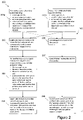
- FIG. 2 is a block diagram of a secure communication protocol between the transmitter 101 and legitimate receiver 102.
- the steps of legitimate communication are shown along branch 200 indicated by solid line arrows.
- the transmitter sends a first data packet including a message vector, an error detection vector, an error correction vector, and a first artificial noise vector, wherein the first artificial noise vector is a function of the legitimate transmitter-receiver channel.
- the transmitter instead sends a first data packet including a message vector, an error detection vector, and a first artificial noise vector, wherein the first artificial noise vector is a function of the legitimate transmitter-receiver channel.
- the legitimate receiver receives the first data packet and subsequently sends a repeat transmission request to the transmitter.
- the transmitter receives the repeat transmission request, and in response sends a second data packet including the message vector, an error detection vector, an error correction vector and a second artificial noise vector, wherein the second artificial noise vector is an inverse vector of the first artificial noise vector such that the first artificial noise vector can be removed.
- the legitimate receiver receives the second data packet, and subsequently combines the first and second data packets such that the first artificial noise vector is removed by the second artificial noise vector.
- the data packets may be combined for example by using a maximal ratio combiner (MRC) at the receiver.
- MRC maximal ratio combiner
- combining methods or diversity techniques may be used, such as selection combining (when the incoming signal with the maximal SNR is selected) or equal gain combining (wherein the same gain is set for each branch of the receiver and the phase of the incoming signals is modified so as to add constructively).
- Figure 2 also shows the steps of attempted eavesdropping along branch 205 indicated by dashed line arrows.
- the eavesdropper receives the first data packet.
- the eavesdropper receives the second data packet.
- the eavesdropper cannot cancel the artificial noise vectors and extract the message vector from the first and second data packets, as the eavesdropper has no knowledge of the legitimate transmitter-receiver channel.
- the above protocol is a combination of FEC with an automatic-repeat-request (ARQ) method, and is referred to as a hybrid automatic-repeat-request (HARQ) protocol.
- ARQ automatic-repeat-request
- HARQ hybrid automatic-repeat-request
- the inventors have discovered that embedding artificial noise with a HARQ protocol as discussed above may allow for improved robustness of the message vector against noise and interference, e.g. in contrast to not using FEC.
- n 1 is natural noise not intrinsic to the communication system at the time of the transmission of the first data packet, and which may for example be described as additive white Gaussian noise (AWGN) but may also include additional noise arising from non-random processes such as interference, ground clutter, self-interference and terrain blocking.
- AWGN additive white Gaussian noise
- the error detection vector may be initially sent with one or more incorrect bits, such as one or more incorrect CRC bits.
- r 1 may be designed so as to automatically force re-transmission. That is, r 1 may purposively contribute to one or more incorrect bits of the error detection vector such that application of the error detection code to the first data packet y 1 will purposively produce an error.
- the legitimate receiver 102 receives the first data packet ⁇ 1 and it multiplies this signal by the complex conjugate of the channel response h b 1 * .
- the FEC decoder e.g. a Viterbi decoder
- the receiver applies the error detection code (e.g., CRC) to decide whether the data is successfully received or not. Since the artificial noise is present in the received vector, the CRC detects an error and the protocol stores y ⁇ 1 in a digital buffer.
- the legitimate receiver 102 then asks for retransmission from the transmitter (e.g., the legitimate receiver 102 sends a negative acknowledgment (NACK) to the transmitter 101, which indicates a repeat transmission request).
- NACK negative acknowledgment
- the legitimate receiver 102 receives the second data packet ⁇ 2 , and it multiplies this incoming signal by the complex conjugate of the channel response h b 2 * .
- FEC decoder e.g. a Viterbi decoder
- the first decoded y ⁇ 1 and the second decoded y ⁇ 2 data packets may then be combined at the legitimate receiver 102 such that the first artificial noise vector is removed by the second artificial noise vector.
- the artificial noise vectors are cancelled.
- the eavesdropper 104 who illegitimately receives the first y 1 and second y 2 data packets, cannot also combine them and cancel the artificial noise vectors r 1 and r 1 in the same way, as the eavesdropper 104 lacks knowledge of both h b 1 and h b 2 as well as the key g.
- the artificial noise key vector g is not transmitted in the open as the legitimate receiver 102 does not need to know it.
- HARQ type-I with artificial noise protocol which has the advantages of increasing the robustness of the communication (e.g. lower bit error rate or packet error rate), or conversely requiring a lower power to be used in the transmission to achieve a similar communication performance to the communication had HARQ type-I not been used.
- the communication system architecture 300 for the HARQ type-I with artificial noise protocol begins with a first transmission sequence, wherein message bits are formed and to which CRC bits 302 are added.
- the message bits and CRC bits are stored in a suitable buffer for transmission (TX buffer) 304.
- TX buffer suitable buffer for transmission
- parameters of the channel 307 are fed back to the transmitter HARQ control 309 through feedback channel 308, either by probing of the channel 307 or provision of CSI from channel 307.
- the parameters of the channel 307 are used to add artificial noise bits 305 to the message bits and CRC bits to form combined digital data bits, and the parameters of the channel 307 are also stored in the TX buffer 304.
- FEC coder bits 303 are subsequently added to the combined digital data bits to form HARQ digital data bits to be transmitted.
- the HARQ digital data bits are then converted into an analogue signal by modulator 306 and is transmitted through channel 307, wherein natural noise 310 not intrinsic to the communication system is added to the analogue signal.
- the communication system architecture 300 further comprises a node 318 which may be an amplifier 318 tuned with the channel or a maximal ration combiner without memory, such as an analogue MRC, configured to remove or minimise the influence of natural noise 310 from the first analogue signal prior to demodulation.
- the analogue signal is then received and converted back into received digital bits at the demodulator 311, and the received digital bits are then input into an FEC decoder 314 (such as a Viterbi decoder 314) and the resulting output is stored in a suitable buffer at the receiver (RX buffer) 312 as a first input into a digital combiner (noise block removal) 313 such as a maximal ratio combiner (MRC), prior to being subject to a CRC error detection check 315. Due to the artificial noise bits 305 present within the received digital data bits, the CRC error check will fail and the receiver HARQ control 316 sends a negative acknowledgement message (NACK) to the transmitter HARQ control 309.
- NACK negative acknowledgement message
- the transmitter HARQ control 309 Upon receipt of the NACK, the transmitter HARQ control 309 instigates a second transmission sequence, wherein re-transmission HARQ digital data bits are formed from the message bits with CRC bits 302 and FEC coder bits added. Simultaneously, parameters of the channel 307 at the time of re-transmission are fed back to the transmitter HARQ control 309 through feedback channel 308.
- a second set of artificial noise bits 305 is calculated from the initial message bits and CRC bits stored in the TX buffer 304 and parameters of the channel 307 at the time of re-transmission, such that the second set of artificial noise bits 305 can be cancelled with the first transmission set of artificial noise bits 305 at the digital noise block removal 313 at the receiver side.
- the second transmission sequence then proceeds in the same way as the first transmission sequence as described above, i.e. the steps from forming the combined digital data bits for the second transmission sequence and storing parameters in the TX buffer 304, through to receiving digital bits of the second transmission sequence and storing them in the RX buffer 312 as a second input into the digital noise block removal 313, are substantially the same as for the first transmission sequence.
- the first and second inputs are combined to form a received signal estimate bits, which cancels the first set of artificial noise bits with the second set of artificial noise bits.
- the received signal estimate bits are then subject to a second CRC error detection check. If the second CRC error check does not detect any errors, then the receiver HARQ control 316 sends a positive acknowledgement message (ACK), and estimated message bits are able to be extracted.
- ACK positive acknowledgement message
- a draw-back of the above HARQ type-I with artificial noise protocol is that, once the coding rate is fixed, all parity/error detection bits for error correction are transmitted even if they are not all needed, thus reducing the efficiency of the transmission and suffering capacity loss in strong signal conditions.
- Equation (10) does not include the error correction vector (FEC) c , and as such this example is referred to as a HARQ type-II with artificial noise protocol.
- Steps 202 and 203 are the same as described above. That is, at step 202, the legitimate receiver 102 receives, decodes and stores the first data packet y ⁇ 1 as in Equation (2) but without using the FEC decoder (since FEC vector is not present), and subsequently sends or otherwise communicates a NACK to the transmitter 101. At step 203, the transmitter responds by sending a second data packet ⁇ 2 as described by Equation (3).
- the legitimate receiver (102) receives and decodes the second data packet y ⁇ 2 and it combines it with the first data packet y ⁇ 1 as in Equation (5).
- the FEC data are not present because Equation (5) applies after the FEC (e.g. Viterbi) decoder.
- the HARQ type-II with artificial noise protocol does not suffer capacity loss in strong signal conditions, as FEC bits are only transmitted on subsequent re-transmissions as needed.
- the transmitter 101 may set the first and second artificial noise vectors according to Equations (8) and (9) such that they satisfy the noise-cancellation criterion of Equation (6) - Equation (7).
- the legitimate receiver 102 may send a positive acknowledgment (ACK) message to the transmitter such that the transmitter 101 does not send further re-transmissions.
- ACK positive acknowledgment
- the above protocols may readily be extended to require more than one repeat transmission.
- the error detection vector d of the second data packet may also include incorrect CRC bits such that the transmitter sends at least a third data packet.
- the artificial noise may be distributed across any suitable number of data packets in such a way that when all of the data packets are processed together the artificial noise can be removed to extract the message.
- FIG. 3B there is shown a communication system architecture 301 for the HARQ type-II with artificial noise protocol.
- Many of the elements of the communication system architecture 301 for the HARQ type-II with artificial noise protocol are identical to corresponding elements in the communication system architecture 300 of Figure 3A and function in an identical way. These components have been given the same reference numerals as they have in Figure 3A and, in the interests of brevity, will not be described in detail again.
- the transmitter 309 and receiver 316 HARQ controls further comprise switching protocols 317 and 320, respectively.
- the communication system architecture 301 for the HARQ type-II with artificial noise protocol begins with a first transmission sequence, wherein message bits are formed and to which CRC bits 302 are added, a similar way as described above in relation to Figure 3A .
- the transmitter switching protocol 317 is set such that FEC coder bits 303 are not added during the first transmission sequence. Rather, as shown in Figure 3B , a first set of artificial noise bits 305 are added to the combined message and CRC bits to form a first combined set of digital data bits without FEC coder bits 303.
- the first combined set of digital data bits are modulated and transmitted in a similar way as described above in relation to Figure 3A .
- the analogue signal is then converted into received digital bits and passed subject to a maximal a posteriori probability estimate (MAP) 319 so as to yield a first set of received digital bits without the influence of natural noise.
- MAP maximal a posteriori probability estimate
- the receiver switch protocol 320 is set such that the first set of received digital bits are subject to a CRC error detection check 315 without passing through FEC decoder 314. That is, in the first transmission sequence, the first set of artificial noise bits can be added without having to consider intermixing the first set of artificial noise bits with the functionality of the FEC coder 303.
- the CRC error check will fail and the receiver HARQ control 316 sends a NACK to the transmitter HARQ control 309 and also stores the first set of received digital bits in a suitable buffer at the receiver (RX buffer) 312.
- the transmitter HARQ control 309 Upon receipt of the NACK, the transmitter HARQ control 309 instigates a second transmission sequence and sets the transmitter switching protocol 317 such that re-transmission HARQ digital data bits are formed from the message bits with CRC bits 302, a second set of artificial noise bits 305, and wherein FEC coder bits 303 are added.
- the second set of artificial noise bits are designed in a similar way as described in relation to Figure 3A , however they must also be added so as to not interfere with the FEC coder bits 303.
- the second transmission sequence then proceeds in the same way as the first transmission sequence as described above, however the receiver HARQ controller 316 sets the receiver switch protocol 320 such that the received re-transmission HARQ digital data bits (comprising message bits, CRC bits, and FEC bits) are then input into the FEC decoder 314. After FEC decoding, the bits are combined with the first set of bits in the RX buffer 312 so as to mutually cancel the first and second artificial noise bits to form received signal estimate bits.
- the received signal estimate bits are subject to a second CRC error detection check 315. If the second CRC error check does not detect any errors, then the receiver HARQ control 316 sends a positive acknowledgement message (ACK), and estimated message bits are able to be extracted.
- ACK positive acknowledgement message
- the NACK or ACK need not be signals explicitly sent from the receiver to the sender.
- the negative acknowledgement may be an implied negative acknowledgement comprising an absence of acknowledgement signal being sent from the receiver to the sender over a pre-determined time period, and wherein interpreting the negative acknowledgement at the sender comprises recognising the absence of acknowledgement signal over the pre-determined time period (e.g. a time-out).
- the sender may thus determine that the error check has failed either in response to an explicit NACK signal from the receiver, or implicitly based on the absence of a positive ACK signal.
- Other arrangements would also be possible.
- the skilled person will understand that other arrangements than transmitting a NACK message would also be possible for triggering the sender to transmit a second or further data packet.
- the artificial noise may in general be distributed across any number of data packets.
- the sender can thus exploit this by predetermining that a set of plural data packets should be transmitted, even without using the HARQ protocol described above.
- the artificial noise bits may be designed to explicitly require a plurality of re-transmission sequences so as to mutually cancel the different sets of artificial noise bits. Indeed, increasing the number of re-transmission sequences may increase the level of security of the entire communication protocol, however at the cost of a reduced throughput.
- the max value of number of retransmissions can be established by the desired level of throughput that the secure physical layer is to provide to the upper layers within the communication layers hierarchy.
- the number of retransmissions M may, for example, be set in accordance with the sender-receiver channel. Since a harsh communication channel (i.e. low SNR channel) needs more retransmissions to transmit the information properly, the proposed strategy can exploit poor channel performance to provide a secure communication. That is, if the channel is bad, the system knows many retransmissions are needed to deliver the information, and thus the retransmissions can be exploited for adding security. The maximal number of retransmissions may depend on the application, i.e. throughput and / or latency requirement.
- Figure 4 shows a block diagram of an embodiment of a secure communication protocol between the transmitter 101 and legitimate receiver 102 which exploits M-transmissions with artificial noise.
- the sender or both the sender and the receiver can set the total number of transmissions M required (i.e., which includes the initial transmission and M-1 retransmissions). That is, setting the number M comprises setting the number at the sender, or setting the number at the sender and the receiver.
- the above transmission steps can then be followed, with the exception that no ACK/NACK is explicitly required to force a retransmission, rather the total number of transmissions is pre-determined the specified number of times (i.e. retransmission is automatic).
- the transmitter sends a data packet including a message vector and an artificial noise vector, wherein the artificial noise vector is still a function of the legitimate transmitter-receiver channel.
- the transmitter may optionally include an error detection vector and may also optionally include an error correction vector.
- the transmitter will also note the number of the data packet in the transmission series (e.g., first data packet, second data packet, ..., m th data packet).
- the legitimate receiver receives and stores the data packet.
- the legitimate receiver notes the number of the data packet in the transmission series. For example, if the receiver is also able to set the number of transmissions required, then the receiver may also note the number of each transmission and thus is able to determine that the transmission series has terminated after M transmissions.
- the transmitter and the receiver determine whether the number of the data packet is the M th data packet in the transmission series (i.e., the pre-determined final data packet). For example, at step 402, the transmitter will have noted the number of each transmission and will stop transmitting further data packets after M transmissions. Accordingly, at step 404, the receiver may determine that the transmission series has terminated after not receiving a subsequent transmission after a pre-determined time-interval, or is otherwise informed by the transmitter. Alternatively, as mentioned above, if the receiver is also able to set the number of transmissions required (i.e. determines M independently of the transmitter), then the receiver is able to determine that the number of the data packet is the M th data packet in the series.
- steps 402-404 are iterated until the number of the data packet reaches M.
- the transmitter may send a data packet also including an error detection vector. That is, error check bits may still be provided for the purposes of detecting normal transmission errors. For example, if an error check does happen to indicate the presence of a transmission error (e.g. arising from the natural noise), then the receiver may send a NACK to the transmitter, and the transmitter may send a corresponding NACK-induced re-transmission for the specific transmission in the series which produced the error. A subsequent ACK would indicate that that specific transmission in the series has now been successfully received such that the transmitter can continue to transmit the subsequent transmissions in the series.
- error check bits may still be provided for the purposes of detecting normal transmission errors. For example, if an error check does happen to indicate the presence of a transmission error (e.g. arising from the natural noise), then the receiver may send a NACK to the transmitter, and the transmitter may send a corresponding NACK-induced re-transmission for the specific transmission in the series which produced the error. A subsequent ACK would indicate that that specific transmission in the series has now been successfully received
- the transmitter may send a data packet also including an error correction vector. That is, similar to the HARQ-based protocols described above, FEC may be added to each transmission within the series (HARQ-I), or only to the final transmission in the series (HARQ-II). Furthermore, FEC may be added to one or more of the transmissions in the series (e.g., on only a subset of the transmissions in the series). For example, if the quality of the sender-receiver channel is detected/indicated as being particularly bad for a particular transmission, then FEC may be added to that particular transmission so as to improve the robustness of that particular transmission.
- the receiver combines all the data packets such that the artificial noise packets of the M data packets are mutually cancelled.
- FIG. 5A schematically shows a bitstream of k-bits input into an FEC coder, which outputs an n-bit symbol or codeword, wherein n is greater than k.
- the encoder outputs n encoded bits, wherein the values are generated by binary functions (such as generator polynomials).
- the n encoded bits depend on K values.
- FEC adds increasing redundancy which lowers the 'goodput' (i.e. the application-level throughput of the communication). So as to mitigate the decrease in goodput, the FEC may be encoded with a higher rate via puncturing.
- the input data can be fed through a convolution coder so as to achieve a 1/2 code rate.
- FEC can be applied with a puncturing rate of 5/6. Puncturing omits some of the encoded bits in the transmitter - thus reducing the number of transmitted bits and increasing the coding rate).
- a dummy "zero" metric is inserted into the convolution decoder on the receiver side in place of the omitted bits.
- introducing FEC into a protocol including ARQ and artificial noise improves performance in poor signal conditions, e.g. in harsh environments such as those subject to jamming or interference.
- the artificial noise needs to be controllably introduced at an appropriate position within the message generation such that the FEC and artificial noise cannot intermix.
- the FEC vector and AN vector are chosen such that application of the FEC code does not inadvertently correct apparent erroneous bits in the data arising from the artificial noise bits, as these have been added intentionally and are to be cancelled by combination with the subsequent data packet. That is, the artificial noise vector is designed to be external to the error-correcting capabilities of the code and the FEC code is chosen to correct an expected subset of all errors that may occur other than those arising from the artificial noise.
- the present embodiments recognise that, in order to controllably introduce the artificial noise in a synergetic way with the FEC bits, the artificial noise should be added as digital bits prior to modulation, e.g. as shown in Figures 3A-3B .
- the FEC coder (303) is applied prior to the additional of the artificial noise (305).
- the artificial noise will need to be designed so as to not affect or mix with the functionality of the FEC coder.
- the FEC coder may be applied with a puncturing operation, however at least some of the omitted encoded bits resulting from the puncturing operation may instead be replaced with artificial noise bits.
- Figure 3B shows the FEC coder (303) being applied after the addition of the artificial noise (305). Accordingly, the FEC coder acts on the entire packet including the message vector and the artificial noise as if the entire packet were the intended payload.
- FIG. 6A there is shown a schematic of the digital to analogue conversion process applied by modulator 306 in Figures 3A-3B without artificial noise being added to the data packet.
- the information is to be transmitted in frames (621).
- several blocks (622) of bits may be modulated or encoded on to multiple carrier frequencies, e.g. via orthogonal frequency-division multiplexing (OFDM).
- the block of bits may each be represented via a specific combination in amplitude and phase, e.g. as shown in the 64-QAM (6 bits per sub-carrier) constellation diagram (623).
- N bpc 4 bits per carrier which corresponds to 16-QAM (quadrature amplitude modulation).
- Noise is to be added to a particular constellation symbol, e.g. symbol 0111.
- the noise generated by Equation (10) is added to the constellation symbol 0111.
- N number of sub-carriers, i.e. symbols per frame
- FIG. 6C there is shown schematically the process of adding artificial noise at the symbol level on a symbol-by-symbol basis within a single frame.
- the impact in the transmitted symbols is limited by symbol-to-symbol changes (as opposed to adding artificial noise within the analogue domain, wherein there is a higher degree of freedom in shifting the modulated symbol, e.g. to a point not landing on a particular constellation symbol)
- adding artificial noise at the "bit level” enables the addition of noise anywhere within the communication chain prior to the modulator and enables the addition of artificial noise in such a way as to remain unaffected by the application of an FEC encoder.
- the flexibility in deciding when to introduce artificial noise within the above protocol may be advantageous.
- introducing artificial noise bits digitally as shown in Figure 6C advantageously enables several degrees of freedom over the design of the artificial noise, for example via: modification of the artificial noise probability distribution function; artificial noise power adjustment; baseband peak-to-average power ration control; and/or phase noise.
- the artificial noise may be designed via controlling the phase noise, such as uniform phase distribution with a constant envelope.
- Figure 7 shows numerical results of the secrecy performance of the protocol of one of the embodiments. As shown, the left-hand panel shows the reduced channel capacity for the eavesdropper as compared to the legitimate receive. As shown in the right-hand panel, the eavesdropper cannot decode the information even if the quality of the signal is good, as the eavesdropper experiences substantial performance degradation even for small amounts of artificial noise.
- the above protocols may further be adapted to incorporate incremental redundancy. That is, every re-transmission contains different information than the previous one. Multiple sets of coded bits are generated, each representing the same set of information bits. The re-transmission typically uses a different set of coded bits than the previous transmission, with different redundancy versions generated by puncturing the encoder output. Thus, at every re-transmission the receiver gains extra information.
- the artificial noise bits for each re-transmission is designed such that the noise cancellation step is unaffected by the puncturing.
- FIGS 8A and 8B there are shown numerical results as a function of increasing number of retransmissions for the legitimate receiver (Bob) and the eavesdropper (Eve).
- the results have the following parameters.
- SNR 45 [dB].
- Figures 8A and 8B use the following definitions.
- BER MAP Bob is the Bob's Bit Error Rate, it is the ratio between the number of bits correctly decoded by the Bob's MAP and the total number of transmitted bits.
- BER MAP Eve is the Eve's Bit Error Rate, it is the ratio between the number of bits correctly decoded by the Eve's MAP and the total number of transmitted bits.
- BER PHY Bob is the Bob's Bit Error Rate at PHY layer, it is the ratio between the number of bits correctly decoded by Bob after the noise removal and the total number of transmitted bits.
- BER PHY Eve is the Eve's Bit Error Rate at PHY layer, it is the ratio between the number of bits correctly decoded by Eve after the noise removal and total number of transmitted bits.
- PER Bob is the Bob's Packet Error Rate, it is the ratio between the number of packets correctly decoded by Bob after the noise removal and the total number of transmitted packets.
- PER Eve is the Eve's Packet Error Rate, it is the ratio between the number of packets correctly decoded by Eve after the noise removal and the total number of transmitted packets.
- Figure 8A shows the numerical results for Eve, and represents PER, BER or Secure throughput (normalized).
- BER MAP Eve is equal to zero because, Eve is able to decode perfectly all the incoming information (high SNR).
- BER PHY Eve is equal to S ⁇ AN b S because she can decode correctly only the bits not corrupted by the artificial noise.
- PER Eve is equal to one because there is at least a not correctly decoded bit in the packet (i.e. the noisy bits).
- Figure 8B shows the numerical results for Bob, and represents TH sec Bob PER Bob , BER PHY Bob , and BER MAP Bob .
- BER MAP Bob depends by the SNR value, so for decreasing values of SNR, the BER increases.
- BPSK is a robust modulation so for SNR ⁇ 2 [dB] the BER is in the order of 3 [%].
- the same behavior applies for BER PHY Bob but the value is higher because it is computed over S - AN b bits instead of S bits.
- PER Bob is equal to 0 (perfect decoding after M retransmission) for SNR > 4.5 [ dB ] .
- PER Bob ⁇ PER Eve .
- TH sec Bob is equal to 1 for SNR > 4.5 [ dB ] . After that it starts decreasing because some of the packets have not been decoded properly after the retransmisisons.
- the above security protocols will function on existing communication hardware which implement HARQ-I and HARQ-II in present communications systems, such as HSDPA and/or LTE, without requiring modification of the hardware. Any suitable and desired communication system may be used.
- the above protocols are applicable to regular single-input-single-output (SISO) systems, e.g. single carrier frequency division multiplex (SC-FDMA), as well as to orthogonal frequency division multiplexing (OFDM) or multiple-input-multiple-output (MIMO) OFDM.
- SISO single-input-single-output
- SC-FDMA single carrier frequency division multiplex
- OFDM orthogonal frequency division multiplexing
- MIMO multiple-input-multiple-output
- the methods in accordance with the technology described herein may be implemented at least partially using software e.g. computer programs.
- the methods are generally computer-implemented methods.
- the technology described herein comprises computer software specifically adapted to carry out the methods herein described when executed by an appropriate processing circuit at the sender/receiver device.
- the processing circuit may be a microprocessor system, a programmable FPGA (field programmable gate array), etc..
- the various functions of the technology described herein can be carried out in any desired and suitable manner.
- the functions of the technology described herein can be implemented in hardware or software, as desired.
- the various functional elements, stages, units, and “means” of the technology described herein may comprise a suitable processor or processors, controller or controllers, functional units, circuits/circuitry, processing logic, microprocessor arrangements, etc., that are operable to perform the various functions, etc., such as appropriately dedicated hardware elements (processing circuitry) and/or programmable hardware elements (processing circuitry) that can be programmed to operate in the desired manner.
- the sender device may comprise a suitable data packet generating circuit that is operable to generate the data packets, as well as a suitable data packet encoding circuit that is operable to add the desired error check and/or FEC bits, depending on the mode of operation.
- the sender device also comprises an appropriate artificial noise introducing circuit that is able to operate in the manner described above. These circuits may be separate or may be part of the same overall processing circuit, as desired.
Landscapes
- Engineering & Computer Science (AREA)
- Computer Networks & Wireless Communication (AREA)
- Signal Processing (AREA)
- Physics & Mathematics (AREA)
- Astronomy & Astrophysics (AREA)
- Aviation & Aerospace Engineering (AREA)
- General Physics & Mathematics (AREA)
- Detection And Prevention Of Errors In Transmission (AREA)
Abstract
Description
- The present disclosure is concerned with communication protocols, and in particular with methods of securely transmitting information from a sender to a receiver, e.g. such that the information cannot be intercepted by third parties (eavesdroppers).
- Various communication protocols exist that are able to securely transmit information. For instance, one example of a secure communication protocol is presented in HAMAMREH, 'Joint PHY/MAC Layer Security Design Using ARQ with MRC and Null-Space Independent PAPR-Aware Artificial Noise in SISO Systems', IEEE TRANSACTIONS ON WIRELESS COMMUNICATIONS, VOL. 17, NO. 9, September 2018, pp 6190-6204.
- The communication protocol described in HAMAMREH involves a chase-combing automatic repeat request (CC-ARQ) protocol, in which analogue noise dependent on the quality of service requirements and a transmitter-legitimate receiver channel condition is added onto the data packet to be communicated. When the legitimate receiver requests a re-transmission, the transmitter adds an appropriately designed cancelling noise to the next data packet. Then, at the receiver, a data packet free of the noise can be obtained using a maximal ratio combining process. Simultaneously the performance of an eavesdropper, who does not know the transmitter-legitimate receiver channel condition, deteriorates.
- In avionic systems, air-to-ground (or, correspondingly, ground-to-air) communications may be safety critical, and as part of this, in order to meet the relevant functional safety standards, a higher degree of security is therefore required. For example, the remote control or communication of an avionic system requires consistent and reliable, secure communication between a transmitter and legitimate receiver. However, such air-to-ground communications consist of communicating along communication channels that may be relatively spaced apart, and in which there may be no clear or consistent line of sight. This may represent a relatively a harsh communications environment, e.g. where the signal to noise ratio (SNR) may be inherently relatively low, such that any communication protocol should desirably be sufficiently robust to address this.
- Therefore, existing secure protocols may not always be suitable for such low signal to noise ratio (SNR) communication scenarios.
- Another example of a communication protocol is the so-called 'hybrid automatic repeat request' (HARQ) scheme in which an original data packet is encoded with a forward error detecting (FEC) code. The FEC code is designed so as to correct a particular or expected subset of possible errors, whereas the ARQ method is used as a fall-back to correct errors that are unable to be corrected using the FEC method on its own.
- HARQ communication schemes are already implemented in some modern communication systems (HSDPA, LTE, etc.). However, an issue regarding the security of a communication arises when using a traditional HARQ communication scheme in air-to-ground communication scenarios.
- In particular, in air-to-ground communication scenarios, where the aircraft is moving, the quality of the eavesdropper-transmitter channel may in some cases be better than the transmitter-legitimate receiver channel. For example, this may occur due to the eavesdropper being spatially closer to the transmitter relative to the distance between the legitimate receiver and the transmitter.
- Therefore, the air-to-ground communication is a so-called 'natural insecure' transmission.
- In such a scenario, the signal quality along the eavesdropper-transmitter channel may be sufficiently high for the eavesdropper to be able to illegitimately decode the communications sent from the transmitter and intended for the legitimate receiver. Moreover, re-transmissions of the data packet according to the HARQ protocol may further increase the eavesdropper's ability to decode the data packet compared to the legitimate receiver.
- Therefore, conventional HARQ communication schemes are not typically adopted for secure communications.
- Thus, it would be desirable to provide an improved, secure communications protocol, in particular that is suitable for use for air-to-ground communications, and other such low signal to noise ratio (SNR) environments.
- A first aspect of the disclosure comprises a method of transmitting a message from a sender to a receiver, wherein the communication between the sender and receiver is performed using a hybrid automatic-repeat-request (HARQ) protocol in which a first data packet to be transmitted from a sender device to a receiver device comprises a first part representing the message to be transmitted and a second part representing an error detection code that can be used by the receiver to perform an error check on the first part of the first data packet, and in which, in the event that the error check fails, the sender device is triggered to transmit to the receiver device a second data packet comprising a corresponding first part representing the message to be transmitted and a second part representing a forward error correction code.
- The method comprises:
- (i) when a message is to be transmitted from the sender to the receiver: generating at the sender device a first data packet, the first data packet including a first part representing the message to be transmitted and a second part representing an error detection code for performing an error check on the first part of the data packet; and digitally introducing at the sender device a first artificial noise component to the first data packet by modifying a set of bits in the first data packet, whereby the first artificial noise value will cause the error check to fail thereby automatically triggering the sender device to transmit a second data packet;
- (ii) the sender device transmitting the first data packet including the introduced first artificial noise component to the receiver device over a sender-receiver communications channel;
- (iii) receiving the first data packet including the first artificial noise component at the receiver device, the receiver device performing an error check on the first data packet;
- (iv) in response to determining that the error check has failed, the sender device generating a second data packet, the second data packet including a corresponding first part representing the message being transmitted and a second part representing a forward error correction code; wherein generating the second data packet further comprises the sender device digitally introducing a second artificial noise component to the second data packet by modifying a set of bits in the second data packet, whereby the second artificial noise component is generated such that the receiver can process the first and second data packets together to remove the introduced artificial noise components to extract the message;
- (v) the sender device transmitting the second data packet including the second artificial noise component to the receiver device over the sender-receiver communications channel; and
- (vi) receiving the second data packet including the second artificial noise component at the receiver device and processing the first and second data packets together to extract the message.
- There is thus provided a communication system that allows for secure communications between a sender device and a receiver device, located remotely from each other.
- The above arrangement may provide various benefits compared to other possible approaches. In particular, the present disclosure recognises that the combination of a hybrid automatic repeat request (HARQ) protocol with forward error correction (FEC), with the intentional introduction of artificial noise to the first data packet in such a manner that the HARQ protocol will automatically trigger (re-transmission of a second data packet, can provide a particularly robust, secure communication scheme suitable for air-to-ground communications.
- For instance, the above arrangements, similarly as in HAMAMREH's approach, encodes the communication by adding artificial noise to the transmitted data packets, with the artificial noise then forcing a re-transmission (an automatic repeat request, ARQ). Corresponding artificial noise is then added to the second data packet to allow the legitimate receiver to cancel the artificial noise that was added to the first data packet and thereby decode the first data packet appropriately. The artificial noise will however wholly deteriorate the signal for any illegitimate receivers (eavesdropping the communication) such that even if the illegitimate channel has a higher quality than the legitimate channel, the artificial noise means that the legitimate user is able to reliably decode the message whereas the eavesdropper cannot. This can help to provide privacy against eavesdropping.
- In contrast to HAMAMREH, however, embodiments of the present disclosure uses a HARQ protocol with FEC. The use of a HARQ protocol with FEC may allow for a more robust communication protocol suitable for poor signal conditions such as long distance air-to-ground communications (e.g. as compared to the approach described in HAMAMREH (which does not use FEC) and may therefore not be suitable for such situations).
- However, because the addition of FEC increases the length of the data packets, with different information potentially being sent in the first/second data packets (e.g., and especially, when using a HARQ-II protocol), the present disclosure recognises that artificial noise should not simply be added to the data packets in an arbitrary manner, and there exists a need to be able to more controllably introduce artificial noise to the data packet.
- Thus, the inventors have recognised that when introducing artificial noise to the data packets in this way, in order to facilitate the use of FEC, it is beneficial for the artificial noise to be introduced digitally, e.g., and in embodiments, before the transmission signal is converted into the analogue domain, as will be explained further below. That is, the artificial noise is added digitally prior to a modulator which is used to convert the digital signal into an analogue signal.
- Furthermore, the digital artificial noise components are in embodiments of the present disclosure introduced before the FEC coding, such that the FEC advantageously covers both the message and the artificial noise. Again, this helps facilitate the use of FEC to provide an improved i.e. more secure and robust communication protocol.
- For instance, in the approach proposed by HAMAMREH, in contrast, artificial noise is instead added to the analogue signal as it is being transmitted, i.e. after the data packet has been generated.
- The present disclosure therefore provides a robust communication protocol for low signal to noise ratio environments, and is therefore particularly suited for use in air-to-ground avionic applications. For instance, in embodiments, the sender device may be provided on-board an aircraft, with the receiver device being located on the ground, e.g. in a control centre or control device for the aircraft (or vice versa with the receiver device being located on-board the aircraft).
- The sender-receiver communication channel itself may use any suitable and desired protocol for transmitting the data packets to/from the sender and receiver devices. In fact it is possible, and it is a benefit of the approach described herein, that the sender-receiver communication channel may utilise existing communication systems such as HSDPA, LTE, etc., without requiring significant modification to the communication channel (or the receiver device). Thus, it is a benefit of the techniques described herein that there is no need for complex, dedicated hardware at the receiver side, at least in some embodiments.
- That is, in embodiments, it is only the sender device that needs to have knowledge of the artificial noise, and the sender device introduces the artificial noise in such a manner within the HARQ/FEC protocol (e.g., by introducing artificial noise which is dependent on the transmitter-receiver channel parameters) so that the receiver device may (and in embodiments does) automatically remove the artificial noise to allow the receiver to decode the desired message accordingly.
- The present disclosure also extends to the operation of the sender device itself.
- Thus, another aspect of the present disclosure comprises a method of transmitting a message from a sender to a receiver, performed at a sender device, wherein the communication between the sender and receiver is performed using a hybrid automatic-repeat-request (HARQ) protocol in which a first data packet to be transmitted from the sender device to a receiver device comprises a first part representing the message to be transmitted and a second part representing an error detection code that can be used by the receiver to perform an error check on the first part of the first data packet, and in which, in the event that the error check fails, the sender device is triggered to transmit to the receiver a second data packet comprising a corresponding first part representing the message to be transmitted and a second part representing a forward error correction code, the method comprising:
- (i) when a message is to be transmitted from the sender to the receiver:
- generating a first data packet, the first data packet including a first part representing the message to be transmitted and a second part representing an error detection code for performing an error check on the first part of the data packet; and
- digitally introducing a first artificial noise component to the first data packet by modifying a set of bits in the first data packet, whereby the first artificial noise component will cause the error check to fail thereby automatically triggering the sender to transmit a second data packet;
- (ii) transmitting the first data packet including the introduced artificial noise component to the receiver device over a sender-receiver communications channel;
- (iii) in response to the sender device determining that the error check has filed, the sender device generating a second data packet, the second data packet including a corresponding first part representing the message being transmitted and a second part representing a forward error correction code; wherein generating the second data packet further comprises digitally introducing a second artificial noise component to the second data packet by modifying a set of bits in the second data packet, whereby the second artificial noise component is generated to allow the first artificial noise component introduced to the first data packet to be removed at the receiver; and
- (iv) transmitting the second data packet including the second artificial noise component to the receiver over the sender-receiver communications channel.
- The sender device may be configured for use as part of the method and system described above and may therefore (and in embodiments does) comprise any and all of the optional features described above in relation to the first and second aspects of the present disclosure.
- The first and second data packets can be processed together at the receiver to remove the artificial noise components and extract the message. Whilst in embodiments this is done using first and second data packets (only), in other embodiments this may be done using more than two data packets, with each data packet's respective artificial noise component being generated such that when all of the data packets are suitably combined the artificial noise components are cancelled, to allow the message to be extracted. Various arrangements would be possible in this regard.
- For instance, in the aspects described above the communication is based on hybrid automatic-repeat-request (HARQ) protocol, in which a second data packet is transmitted in response to determining that an error check performed at the receiver has failed. For example, in response to the receiver determining that the error check has failed, the receiver may send a negative acknowledgement signal (NACK) to the sender, which negative acknowledgement signal (NACK) triggers the sender to transmit a second data packet. However, other arrangements would be possible for triggering the second transmission. For instance, the sender may automatically transmit a second data packet after a time-out conditions, e.g. in response to not receiving a positive acknowledgement signal from the receiver.
- However, it would also be possible to introduce artificial noise this way in other communications, that do not rely on a hybrid automatic-repeat-request (HARQ) protocol. For instance, the sender may predetermine that it will send a set of M data packets, and can then generate the artificial noise components appropriately based on its knowledge that it will send such set of M data packets. For example, the number of transmissions may be determined based on the channel quality. In this way it is possible to effectively take advantage of the low channel quality by distributing the artificial noise components across the set of M data packets such that the message can only be extracted once the whole set of M data packets is received.
- A further aspect of the disclosure thus comprises a method of transmitting a message from a sender to a receiver, the method comprising:
- (i) when a message is to be transmitted from the sender to the receiver:
- the sender determining that a set number of plural data packets should be transmitted from the sender to the receiver;
- generating at the sender a first data packet, the first data packet including a first part representing the message to be transmitted; and
- digitally introducing a first artificial noise component to the first data packet by modifying a set of bits in the first data packet;
- (ii) transmitting the first data packet including the introduced first artificial noise component to the receiver over a sender-receiver communications channel;
- (iii) receiving and digitally storing the first data packet including the first artificial noise component at the receiver;
- (iv) repeating steps (i)-(iii) for one or more further data packets up to the set number of data packets to be sent from the sender to the receiver, each data packet including a first part representing the message to be transmitted and a respective artificial noise component, whereby the artificial noise components of the one or more further data packets are generated such that when the set number of data packets are processed together at the receiver their respective artificial noise components can be removed so that the message can be extracted; and
- (vii) the receiver processing the set of plural data packets together to extract the message.
- A yet further aspect of the disclosure comprises a method (performed at the sender device) of transmitting a message from a sender to a receiver, the method comprising:
- (i) when a message is to be transmitted from the sender to the receiver:
- the sender determining that a set number of plural data packets should be transmitted from the sender to the receiver;
- generating at the sender a first data packet, the first data packet including a first part representing the message to be transmitted; and
- digitally introducing a first artificial noise component to the first data packet by modifying a set of bits in the first data packet;
- (ii) transmitting the first data packet including the introduced first artificial noise component to the receiver over a sender-receiver communications channel; and
- (iii) repeating steps (i)-(ii) for one or more further data packets up to the set number of data packets to be sent from the sender to the receiver, each data packet including a first part representing the message to be transmitted and a respective artificial noise component, whereby the artificial noise components of the one or more further data packets are generated such that when the set number of data packets are processed together at the receiver their respective artificial noise components can be removed so that the message can be extracted.
- In these aspects, the number of transmissions to be sent from the sender to the receiver may, e.g., be determined as a function of a desired through-put level and a sender-receiver communication channel signal-to-noise ratio. The receiver may also have knowledge of the set number of data packets being transmitted. For example, the receiver may independently determine how many data packets should be transmitted, e.g. using the same function as the sender, based on the desired through-put level and a sender-receiver communication channel signal-to-noise ratio. Or, the number of data packets may be generated at one of the sender or receiver and then transmitted to the other appropriately.
- Other arrangements would however be possible. For instance, it would be possible that the receiver does not know how many data packets to expect, but the processing at the receiver can nonetheless determine when a sufficient number of data packets (i.e. the set number) has been received to extract the message. For instance, the receiver may process all of the received data packets each time a new data packet is received and may thus be able to dynamically determine whether the full set of data packets has been received, e.g. based on the result of the processing, e.g. based on the processing providing a coherent message.
- The method and sender device in these further aspects may (and in embodiments does) comprise any and all of the optional features described above in relation to the first aspect of the present disclosure to the extent they are not mutually exclusive.
- Embodiments will now be described, by way of example only, with reference to the drawings.
-
-
Figure 1 is a diagram illustrating air-to-ground communication; -
Figure 2 is a block diagram of a secure communication protocol between the transmitter and legitimate receiver; -
Figure 3A is a schematic of a communication system architecture for a HARQ type-I with artificial noise protocol; -
Figure 3B is a schematic of a communication system architecture for a HARQ type-II with artificial noise protocol; -
Figure 4 is a block diagram of another embodiment of a secure communication protocol between the transmitter and legitimate receiver; -
Figure 5A is a schematic of a bitstream of k-bits input into an FEC coder, which outputs an n-bit symbol;Figure 5B is a schematic of a K-length encoder;Figure 5C is a schematic of an FEC puncturing operation; -
Figure 6A is a schematic of the digital to analogue conversion process applied by a modulator;Figure 6B is a schematic representation of digital artificial noise creation;Figure 6C is a schematic of the process of adding artificial noise at the symbol level on a symbol-by-symbol basis within a single frame; and -
Figure 7 shows numerical results of the secrecy performance of the protocol of one of the embodiments. -
Figures 8A and 8B show numerical results of the secrecy performance of the protocol of one of the embodiments as a function of number of transmissions. - The present disclosure relates to secure communication protocols. A particular example will be described now in relation to an aircraft communication system, such as an air-to-ground (or ground-to-air) communication between an aircraft and a ground-based receiver. However besides aerospace, the technology described herein may also find utility in other any other suitable such systems in which secure communications may be desired such as automotive vehicle-to-everything (V2X) wireless communication systems, tactical communications (e.g. military), unmanned vehicles, surveillance, or the like.
-
Figure 1 shows a diagram illustrating air-to-ground communication between a transmitter orsender 101, denoted as Alice, and an intendedreceiver 102, denoted as Bob. Thetransmitter 101 and the intendedreceiver 102 are legitimate users, wherein information is to be securely transmitted through signals from thetransmitter 101 to the intendedreceiver 102 along a legitimate transmitter-receiver channel 103. Thetransmitter 101 may comprise an isotropic transmitter or antenna such that signals comprising information are distributed over a range of directions. As will be appreciated, the channel conditions may be time-varying such that the channel state information (CSI) will correspondingly be time-varying. For example, if thetransmitter 101 is moving relative to thelegitimate receiver 102, the channel state information (CSI) may be time varying due to the corresponding Doppler shift. Many other variables may contribute to time-varying channel conditions, such as variable weather or variable cosmic radiation (e.g. from solar events). - Also shown in
Figure 1 is an illegitimate receiver oreavesdropper 104, denoted as Eve. Theeavesdropper 104 may also receive signals from thetransmitter 101 along a transmitter-eavesdropper channel 105. Theeavesdropper 104 may, for instance, be a passive listener of the signals from thetransmitter 101 intended for the intendedreceiver 102. - The
transmitter 101 may be in a route phase of flight. As will be understood, in some scenarios the transmitter-eavesdropper channel 105 may be better than the legitimate transmitter-receiver channel 103. For example, in some instances, theeavesdropper 104 may be physically closer to thetransmitter 101 than thelegitimate receiver 102. Moreover, theeavesdropper 104 may be able to jam or interfere with the legitimate transmitter-receiver channel 103 so as to deteriorate or reduce the signal to noise ratio (SNR) along the legitimate transmitter-receiver channel 103. -
Figure 2 is a block diagram of a secure communication protocol between thetransmitter 101 andlegitimate receiver 102. The steps of legitimate communication are shown alongbranch 200 indicated by solid line arrows. Atstep 201a, the transmitter sends a first data packet including a message vector, an error detection vector, an error correction vector, and a first artificial noise vector, wherein the first artificial noise vector is a function of the legitimate transmitter-receiver channel. Alternatively, atstep 201b, the transmitter instead sends a first data packet including a message vector, an error detection vector, and a first artificial noise vector, wherein the first artificial noise vector is a function of the legitimate transmitter-receiver channel. Atstep 202, the legitimate receiver receives the first data packet and subsequently sends a repeat transmission request to the transmitter. Atstep 203, the transmitter receives the repeat transmission request, and in response sends a second data packet including the message vector, an error detection vector, an error correction vector and a second artificial noise vector, wherein the second artificial noise vector is an inverse vector of the first artificial noise vector such that the first artificial noise vector can be removed. Atstep 204, the legitimate receiver receives the second data packet, and subsequently combines the first and second data packets such that the first artificial noise vector is removed by the second artificial noise vector. The data packets may be combined for example by using a maximal ratio combiner (MRC) at the receiver. Alternatively or in addition to, other combining methods or diversity techniques may be used, such as selection combining (when the incoming signal with the maximal SNR is selected) or equal gain combining (wherein the same gain is set for each branch of the receiver and the phase of the incoming signals is modified so as to add constructively). -
Figure 2 also shows the steps of attempted eavesdropping alongbranch 205 indicated by dashed line arrows. Atstep 206, the eavesdropper receives the first data packet. Atstep 207, the eavesdropper receives the second data packet. Atstep 208, the eavesdropper cannot cancel the artificial noise vectors and extract the message vector from the first and second data packets, as the eavesdropper has no knowledge of the legitimate transmitter-receiver channel. - Therefore, as will be understood, the above protocol is a combination of FEC with an automatic-repeat-request (ARQ) method, and is referred to as a hybrid automatic-repeat-request (HARQ) protocol. In particular, the inventors have discovered that embedding artificial noise with a HARQ protocol as discussed above may allow for improved robustness of the message vector against noise and interference, e.g. in contrast to not using FEC.
- In the following mathematical formulation, bold indicates vectors of digital values and bold italic indicates vector for analog values. In a first example, at
step 201a, the transmission of the first data packet at the receiver may be described as
- At
step 202, thelegitimate receiver 102 receives the first data packet ỹ 1 and it multiplies this signal by the complex conjugate of the channelresponse 
legitimate receiver 102 may then map the resulting signal to the closer symbol using a Maximum-A-Posteriori receiver, and after applying the FEC decoder (e.g. a Viterbi decoder) it obtains a set of bits:
legitimate receiver 102 then asks for retransmission from the transmitter (e.g., thelegitimate receiver 102 sends a negative acknowledgment (NACK) to thetransmitter 101, which indicates a repeat transmission request). - At
step 203, the transmitter receives the repeat transmission request, and in response sends a second data packet, which may be described as:
- At
step 204, thelegitimate receiver 102 receives the second data packet ỹ 2 , and it multiplies this incoming signal by the complex conjugate of the channelresponse 
legitimate receiver 102 may then map the resulting signal to the closer symbol using a Maximum-A-Posteriori receiver, and after applying the FEC decoder (e.g. a Viterbi decoder) it obtains a set of bits:
legitimate receiver 102 such that the first artificial noise vector is removed by the second artificial noise vector. As an example, a simple addition of Equation (3) and (4) leads to:

- The noise-cancellation criteria may be forced because the
transmitter 101 knows the parameters of the legitimate receiver's 102 channel, i.e. thetransmitter 101 is aware of h b1 and h b2 either by its own probing of the channel or by CSI obtained from thelegitimate receiver 102. Accordingly, atsteps transmitter 101 may set the first and second artificial noise vectors such that the corresponding analog errors satisfy:


eavesdropper 104, who illegitimately receives the first y 1 and second y 2 data packets, cannot also combine them and cancel the artificial noise vectors r 1 and r 1 in the same way, as theeavesdropper 104 lacks knowledge of both h b1 and h b2 as well as the key g. Moreover, the artificial noise key vector g is not transmitted in the open as thelegitimate receiver 102 does not need to know it. - The above example is referred to as a HARQ type-I with artificial noise protocol, which has the advantages of increasing the robustness of the communication (e.g. lower bit error rate or packet error rate), or conversely requiring a lower power to be used in the transmission to achieve a similar communication performance to the communication had HARQ type-I not been used.
- Referring now to
Figure 3A , there is shown an exemplarycommunication system architecture 300 for the HARQ type-I with artificial noise protocol. Thecommunication system architecture 300 for the HARQ type-I with artificial noise protocol begins with a first transmission sequence, wherein message bits are formed and to whichCRC bits 302 are added. The message bits and CRC bits are stored in a suitable buffer for transmission (TX buffer) 304. Simultaneously, parameters of thechannel 307 are fed back to thetransmitter HARQ control 309 throughfeedback channel 308, either by probing of thechannel 307 or provision of CSI fromchannel 307. The parameters of thechannel 307 are used to addartificial noise bits 305 to the message bits and CRC bits to form combined digital data bits, and the parameters of thechannel 307 are also stored in theTX buffer 304.FEC coder bits 303 are subsequently added to the combined digital data bits to form HARQ digital data bits to be transmitted. The HARQ digital data bits are then converted into an analogue signal bymodulator 306 and is transmitted throughchannel 307, whereinnatural noise 310 not intrinsic to the communication system is added to the analogue signal. Thecommunication system architecture 300 further comprises anode 318 which may be anamplifier 318 tuned with the channel or a maximal ration combiner without memory, such as an analogue MRC, configured to remove or minimise the influence ofnatural noise 310 from the first analogue signal prior to demodulation. The analogue signal is then received and converted back into received digital bits at thedemodulator 311, and the received digital bits are then input into an FEC decoder 314 (such as a Viterbi decoder 314) and the resulting output is stored in a suitable buffer at the receiver (RX buffer) 312 as a first input into a digital combiner (noise block removal) 313 such as a maximal ratio combiner (MRC), prior to being subject to a CRCerror detection check 315. Due to theartificial noise bits 305 present within the received digital data bits, the CRC error check will fail and thereceiver HARQ control 316 sends a negative acknowledgement message (NACK) to thetransmitter HARQ control 309. - Upon receipt of the NACK, the
transmitter HARQ control 309 instigates a second transmission sequence, wherein re-transmission HARQ digital data bits are formed from the message bits withCRC bits 302 and FEC coder bits added. Simultaneously, parameters of thechannel 307 at the time of re-transmission are fed back to thetransmitter HARQ control 309 throughfeedback channel 308. A second set ofartificial noise bits 305 is calculated from the initial message bits and CRC bits stored in theTX buffer 304 and parameters of thechannel 307 at the time of re-transmission, such that the second set ofartificial noise bits 305 can be cancelled with the first transmission set ofartificial noise bits 305 at the digitalnoise block removal 313 at the receiver side. The second transmission sequence then proceeds in the same way as the first transmission sequence as described above, i.e. the steps from forming the combined digital data bits for the second transmission sequence and storing parameters in theTX buffer 304, through to receiving digital bits of the second transmission sequence and storing them in theRX buffer 312 as a second input into the digitalnoise block removal 313, are substantially the same as for the first transmission sequence. At the digitalnoise block removal 313, the first and second inputs are combined to form a received signal estimate bits, which cancels the first set of artificial noise bits with the second set of artificial noise bits. The received signal estimate bits are then subject to a second CRC error detection check. If the second CRC error check does not detect any errors, then thereceiver HARQ control 316 sends a positive acknowledgement message (ACK), and estimated message bits are able to be extracted. - A draw-back of the above HARQ type-I with artificial noise protocol is that, once the coding rate is fixed, all parity/error detection bits for error correction are transmitted even if they are not all needed, thus reducing the efficiency of the transmission and suffering capacity loss in strong signal conditions.
- In an alternative second example, at
step 201b, the transmission of the first data packet may be described as
-
Steps step 202, thelegitimate receiver 102 receives, decodes and stores the first data packet y̅1 as in Equation (2) but without using the FEC decoder (since FEC vector is not present), and subsequently sends or otherwise communicates a NACK to thetransmitter 101. Atstep 203, the transmitter responds by sending a second data packet ỹ 2 as described by Equation (3). - At
step 204, the legitimate receiver (102) receives and decodes the second data packet y̅2 and it combines it with the first data packet y̅1 as in Equation (5). Observe that, the FEC data are not present because Equation (5) applies after the FEC (e.g. Viterbi) decoder. As will be appreciated, the HARQ type-II with artificial noise protocol does not suffer capacity loss in strong signal conditions, as FEC bits are only transmitted on subsequent re-transmissions as needed. - Accordingly, in a similar way as above, at
steps transmitter 101 may set the first and second artificial noise vectors according to Equations (8) and (9) such that they satisfy the noise-cancellation criterion of Equation (6) - Equation (7). - At
step 204 of the above protocols, thelegitimate receiver 102 may send a positive acknowledgment (ACK) message to the transmitter such that thetransmitter 101 does not send further re-transmissions. Alternatively, as will be understood, the above protocols may readily be extended to require more than one repeat transmission. For example, the error detection vector d of the second data packet may also include incorrect CRC bits such that the transmitter sends at least a third data packet. Thus, in general, in all embodiments of the disclosure, the artificial noise may be distributed across any suitable number of data packets in such a way that when all of the data packets are processed together the artificial noise can be removed to extract the message. - Referring now to
Figure 3B , there is shown acommunication system architecture 301 for the HARQ type-II with artificial noise protocol. Many of the elements of thecommunication system architecture 301 for the HARQ type-II with artificial noise protocol are identical to corresponding elements in thecommunication system architecture 300 ofFigure 3A and function in an identical way. These components have been given the same reference numerals as they have inFigure 3A and, in the interests of brevity, will not be described in detail again. - In the
communication system architecture 301 for the HARQ type-II with artificial noise protocol, thetransmitter 309 andreceiver 316 HARQ controls further comprise switchingprotocols communication system architecture 301 for the HARQ type-II with artificial noise protocol begins with a first transmission sequence, wherein message bits are formed and to whichCRC bits 302 are added, a similar way as described above in relation toFigure 3A . However, thetransmitter switching protocol 317 is set such that FEC coderbits 303 are not added during the first transmission sequence. Rather, as shown inFigure 3B , a first set ofartificial noise bits 305 are added to the combined message and CRC bits to form a first combined set of digital data bits withoutFEC coder bits 303. The first combined set of digital data bits are modulated and transmitted in a similar way as described above in relation toFigure 3A . - The analogue signal is then converted into received digital bits and passed subject to a maximal a posteriori probability estimate (MAP) 319 so as to yield a first set of received digital bits without the influence of natural noise. During the first transmission sequence, the
receiver switch protocol 320 is set such that the first set of received digital bits are subject to a CRC error detection check 315 without passing throughFEC decoder 314. That is, in the first transmission sequence, the first set of artificial noise bits can be added without having to consider intermixing the first set of artificial noise bits with the functionality of theFEC coder 303. - In a similar way as described above in relation to
Figure 3A , due to theartificial noise bits 305 present within the received digital data bits, the CRC error check will fail and thereceiver HARQ control 316 sends a NACK to thetransmitter HARQ control 309 and also stores the first set of received digital bits in a suitable buffer at the receiver (RX buffer) 312. - Upon receipt of the NACK, the
transmitter HARQ control 309 instigates a second transmission sequence and sets thetransmitter switching protocol 317 such that re-transmission HARQ digital data bits are formed from the message bits withCRC bits 302, a second set ofartificial noise bits 305, and whereinFEC coder bits 303 are added. As will be appreciated, the second set of artificial noise bits are designed in a similar way as described in relation toFigure 3A , however they must also be added so as to not interfere with theFEC coder bits 303. - The second transmission sequence then proceeds in the same way as the first transmission sequence as described above, however the
receiver HARQ controller 316 sets thereceiver switch protocol 320 such that the received re-transmission HARQ digital data bits (comprising message bits, CRC bits, and FEC bits) are then input into theFEC decoder 314. After FEC decoding, the bits are combined with the first set of bits in theRX buffer 312 so as to mutually cancel the first and second artificial noise bits to form received signal estimate bits. The received signal estimate bits are subject to a second CRCerror detection check 315. If the second CRC error check does not detect any errors, then thereceiver HARQ control 316 sends a positive acknowledgement message (ACK), and estimated message bits are able to be extracted. - As will be understood for both of the above protocols, if the second CRC error detection check detects an error, then a further NACK message can be sent to the transmitter, and the first transmission and re-transmission processes can be repeated, with the artificial noise bits modified accordingly. As will be understood, the NACK or ACK need not be signals explicitly sent from the receiver to the sender. For example, the negative acknowledgement may be an implied negative acknowledgement comprising an absence of acknowledgement signal being sent from the receiver to the sender over a pre-determined time period, and wherein interpreting the negative acknowledgement at the sender comprises recognising the absence of acknowledgement signal over the pre-determined time period (e.g. a time-out). The sender may thus determine that the error check has failed either in response to an explicit NACK signal from the receiver, or implicitly based on the absence of a positive ACK signal. Other arrangements would also be possible. Thus, the skilled person will understand that other arrangements than transmitting a NACK message would also be possible for triggering the sender to transmit a second or further data packet.
- As mentioned above, the artificial noise may in general be distributed across any number of data packets. The sender can thus exploit this by predetermining that a set of plural data packets should be transmitted, even without using the HARQ protocol described above. Thus, alternatively or additionally, the artificial noise bits may be designed to explicitly require a plurality of re-transmission sequences so as to mutually cancel the different sets of artificial noise bits. Indeed, increasing the number of re-transmission sequences may increase the level of security of the entire communication protocol, however at the cost of a reduced throughput. The max value of number of retransmissions can be established by the desired level of throughput that the secure physical layer is to provide to the upper layers within the communication layers hierarchy.
- Moreover, in particular for the HARQ type-II with artificial noise protocol, further re-transmissions allow the bits to be re-transmitted to be encoded in different ways at each re-transmission so as to further increase the level of security.
- The number of retransmissions M may, for example, be set in accordance with the sender-receiver channel. Since a harsh communication channel (i.e. low SNR channel) needs more retransmissions to transmit the information properly, the proposed strategy can exploit poor channel performance to provide a secure communication. That is, if the channel is bad, the system knows many retransmissions are needed to deliver the information, and thus the retransmissions can be exploited for adding security. The maximal number of retransmissions may depend on the application, i.e. throughput and / or latency requirement.
- For example,
Figure 4 shows a block diagram of an embodiment of a secure communication protocol between thetransmitter 101 andlegitimate receiver 102 which exploits M-transmissions with artificial noise. Atstep 401, for a desired throughput level and a given/measured signal-to-noise ratio of the sender-receiver communication channel, either the sender or both the sender and the receiver can set the total number of transmissions M required (i.e., which includes the initial transmission and M-1 retransmissions). That is, setting the number M comprises setting the number at the sender, or setting the number at the sender and the receiver. The above transmission steps can then be followed, with the exception that no ACK/NACK is explicitly required to force a retransmission, rather the total number of transmissions is pre-determined the specified number of times (i.e. retransmission is automatic). - For example, at
step 401, the transmitter sends a data packet including a message vector and an artificial noise vector, wherein the artificial noise vector is still a function of the legitimate transmitter-receiver channel. As will be discussed below, the transmitter may optionally include an error detection vector and may also optionally include an error correction vector. Atstep 402, the transmitter will also note the number of the data packet in the transmission series (e.g., first data packet, second data packet, ..., mth data packet). - At
step 403, the legitimate receiver receives and stores the data packet. Optionally, atstep 403, the legitimate receiver notes the number of the data packet in the transmission series. For example, if the receiver is also able to set the number of transmissions required, then the receiver may also note the number of each transmission and thus is able to determine that the transmission series has terminated after M transmissions. - At
step 404, the transmitter and the receiver determine whether the number of the data packet is the Mth data packet in the transmission series (i.e., the pre-determined final data packet). For example, atstep 402, the transmitter will have noted the number of each transmission and will stop transmitting further data packets after M transmissions. Accordingly, atstep 404, the receiver may determine that the transmission series has terminated after not receiving a subsequent transmission after a pre-determined time-interval, or is otherwise informed by the transmitter. Alternatively, as mentioned above, if the receiver is also able to set the number of transmissions required (i.e. determines M independently of the transmitter), then the receiver is able to determine that the number of the data packet is the Mth data packet in the series. - If the data packet is not the Mth data packet in the series, then steps 402-404 are iterated until the number of the data packet reaches M.
- As mentioned above, at
step 401, the transmitter may send a data packet also including an error detection vector. That is, error check bits may still be provided for the purposes of detecting normal transmission errors. For example, if an error check does happen to indicate the presence of a transmission error (e.g. arising from the natural noise), then the receiver may send a NACK to the transmitter, and the transmitter may send a corresponding NACK-induced re-transmission for the specific transmission in the series which produced the error. A subsequent ACK would indicate that that specific transmission in the series has now been successfully received such that the transmitter can continue to transmit the subsequent transmissions in the series. - In addition, at
step 401, the transmitter may send a data packet also including an error correction vector. That is, similar to the HARQ-based protocols described above, FEC may be added to each transmission within the series (HARQ-I), or only to the final transmission in the series (HARQ-II). Furthermore, FEC may be added to one or more of the transmissions in the series (e.g., on only a subset of the transmissions in the series). For example, if the quality of the sender-receiver channel is detected/indicated as being particularly bad for a particular transmission, then FEC may be added to that particular transmission so as to improve the robustness of that particular transmission. - Once the number of the data packet reaches M, at
step 405, the receiver combines all the data packets such that the artificial noise packets of the M data packets are mutually cancelled. As will be understood, if r m is the artificial noise vector added to the m th data packet in the series (where m = 1,2, ..., M ), then the artificial noise vectors will be generated so as to satisfy the following criterion:
- As shown in
Figures 5A-5C , FEC functions by adding redundant bits to the data packet to help detect and correct some transmission errors without the need for retransmission.Figure 5A schematically shows a bitstream of k-bits input into an FEC coder, which outputs an n-bit symbol or codeword, wherein n is greater than k. As shown inFigure 5B , k-bit at a time enter into a K-length encoder (usually k=1, that is, only 1 bit at a time (sample) enters in the encoder). The encoder outputs n encoded bits, wherein the values are generated by binary functions (such as generator polynomials). The n encoded bits depend on K values. As will be appreciated, FEC adds increasing redundancy which lowers the 'goodput' (i.e. the application-level throughput of the communication). So as to mitigate the decrease in goodput, the FEC may be encoded with a higher rate via puncturing. As shown inFigure 5C , the input data can be fed through a convolution coder so as to achieve a 1/2 code rate. The 1/2 code rate can further be fed through a puncturing matrix to achieve other code rates, such as R=2/3 or R=3/4 as shown. In some embodiments, FEC can be applied with a puncturing rate of 5/6. Puncturing omits some of the encoded bits in the transmitter - thus reducing the number of transmitted bits and increasing the coding rate). A dummy "zero" metric is inserted into the convolution decoder on the receiver side in place of the omitted bits. - Therefore, introducing FEC into a protocol including ARQ and artificial noise improves performance in poor signal conditions, e.g. in harsh environments such as those subject to jamming or interference. However, as recognised by the present embodiments, the artificial noise needs to be controllably introduced at an appropriate position within the message generation such that the FEC and artificial noise cannot intermix.
- Accordingly, in the above protocols, the FEC vector and AN vector are chosen such that application of the FEC code does not inadvertently correct apparent erroneous bits in the data arising from the artificial noise bits, as these have been added intentionally and are to be cancelled by combination with the subsequent data packet. That is, the artificial noise vector is designed to be external to the error-correcting capabilities of the code and the FEC code is chosen to correct an expected subset of all errors that may occur other than those arising from the artificial noise.
- The present embodiments recognise that, in order to controllably introduce the artificial noise in a synergetic way with the FEC bits, the artificial noise should be added as digital bits prior to modulation, e.g. as shown in
Figures 3A-3B . For example, as shown inFigure 3A , the FEC coder (303) is applied prior to the additional of the artificial noise (305). As will be appreciated, the artificial noise will need to be designed so as to not affect or mix with the functionality of the FEC coder. For instance, the FEC coder may be applied with a puncturing operation, however at least some of the omitted encoded bits resulting from the puncturing operation may instead be replaced with artificial noise bits. In contrast,Figure 3B shows the FEC coder (303) being applied after the addition of the artificial noise (305). Accordingly, the FEC coder acts on the entire packet including the message vector and the artificial noise as if the entire packet were the intended payload. - Referring to
Figure 6A , there is shown a schematic of the digital to analogue conversion process applied bymodulator 306 inFigures 3A-3B without artificial noise being added to the data packet. As will be appreciated, the information is to be transmitted in frames (621). For example, several blocks (622) of bits may be modulated or encoded on to multiple carrier frequencies, e.g. via orthogonal frequency-division multiplexing (OFDM). The block of bits may each be represented via a specific combination in amplitude and phase, e.g. as shown in the 64-QAM (6 bits per sub-carrier) constellation diagram (623). - Referring to
Figure 6B , there is shown a schematic representation of digital artificial noise creation. For example, consider a set of Nbpc bits per carrier, e.g. Nbpc = 4 bits per carrier which corresponds to 16-QAM (quadrature amplitude modulation). Noise is to be added to a particular constellation symbol, e.g. symbol 0111. A random artificial noise sample may be generated via
Figure 6B this is therefore 1000 -0111 = 0001. This difference dn is the digital noise to be added to the initial set of bits. For example, as shown inFigure 6B , this would be 0111 + 0001 = 1000. The above described process is then iterated on N (number of sub-carriers, i.e. symbols per frame) such that g = [g 1 g 2 ...gN ] represents a vector of N complex numbers. - It will be appreciated that the above process need not be iterated on every integer within the series n = 1,..., N - but rather may be iterated on a pre-defined subset of integers.
- Referring to
Figure 6C , there is shown schematically the process of adding artificial noise at the symbol level on a symbol-by-symbol basis within a single frame. Although the impact in the transmitted symbols is limited by symbol-to-symbol changes (as opposed to adding artificial noise within the analogue domain, wherein there is a higher degree of freedom in shifting the modulated symbol, e.g. to a point not landing on a particular constellation symbol), it will be appreciated that adding artificial noise at the "bit level" enables the addition of noise anywhere within the communication chain prior to the modulator and enables the addition of artificial noise in such a way as to remain unaffected by the application of an FEC encoder. As will be appreciated, the flexibility in deciding when to introduce artificial noise within the above protocol may be advantageous. - Moreover, introducing artificial noise bits digitally as shown in
Figure 6C advantageously enables several degrees of freedom over the design of the artificial noise, for example via: modification of the artificial noise probability distribution function; artificial noise power adjustment; baseband peak-to-average power ration control; and/or phase noise. For example, the artificial noise may be designed via controlling the phase noise, such as uniform phase distribution with a constant envelope.Figure 7 shows numerical results of the secrecy performance of the protocol of one of the embodiments. As shown, the left-hand panel shows the reduced channel capacity for the eavesdropper as compared to the legitimate receive. As shown in the right-hand panel, the eavesdropper cannot decode the information even if the quality of the signal is good, as the eavesdropper experiences substantial performance degradation even for small amounts of artificial noise. - The above protocols may further be adapted to incorporate incremental redundancy. That is, every re-transmission contains different information than the previous one. Multiple sets of coded bits are generated, each representing the same set of information bits. The re-transmission typically uses a different set of coded bits than the previous transmission, with different redundancy versions generated by puncturing the encoder output. Thus, at every re-transmission the receiver gains extra information. The artificial noise bits for each re-transmission is designed such that the noise cancellation step is unaffected by the puncturing.
- Turning now to
Figures 8A and 8B , there are shown numerical results as a function of increasing number of retransmissions for the legitimate receiver (Bob) and the eavesdropper (Eve). The results have the following parameters. For frrame transmission: frame size is S=120 [bit]; modulation is BPSK (1 bit per symbol); and 10 packets are transmitted. For Eve's channel: SNR=45 [dB]. For Bob's channel: SNR_m=45 [dB]/M, with the number of retransmission M=2,...,20. Number of noisy bits is: AN =3+6-m; where m=1,...,/2 - different when number of retransmissions has been set. Eve's has an "almost perfect" channel - high SNR, however the ratio: |h_ e |∧2/|h_ b|∧2 has been selected to avoid Eve to decode the artificial noise. On Bob's side, he knows how to remove the artificial noise but some bits maybe corrupted because the low SNR. -
Figures 8A and 8B use the following definitions.


-
Figure 8A shows the numerical results for Eve, and represents PER, BER or Secure throughput (normalized). As shown inframe 801,


-
Figure 8B shows the numerical results for Bob, and represents


frame 802,


- The above security protocols will function on existing communication hardware which implement HARQ-I and HARQ-II in present communications systems, such as HSDPA and/or LTE, without requiring modification of the hardware. Any suitable and desired communication system may be used.
- Moreover, the above protocols are applicable to regular single-input-single-output (SISO) systems, e.g. single carrier frequency division multiplex (SC-FDMA), as well as to orthogonal frequency division multiplexing (OFDM) or multiple-input-multiple-output (MIMO) OFDM.
- The methods in accordance with the technology described herein may be implemented at least partially using software e.g. computer programs. Thus, the methods are generally computer-implemented methods. It will thus be seen that when viewed from further embodiments the technology described herein comprises computer software specifically adapted to carry out the methods herein described when executed by an appropriate processing circuit at the sender/receiver device. The processing circuit may be a microprocessor system, a programmable FPGA (field programmable gate array), etc..
- However, in general, the various functions of the technology described herein can be carried out in any desired and suitable manner. For example, the functions of the technology described herein can be implemented in hardware or software, as desired. Thus, for example, unless otherwise indicated, the various functional elements, stages, units, and "means" of the technology described herein may comprise a suitable processor or processors, controller or controllers, functional units, circuits/circuitry, processing logic, microprocessor arrangements, etc., that are operable to perform the various functions, etc., such as appropriately dedicated hardware elements (processing circuitry) and/or programmable hardware elements (processing circuitry) that can be programmed to operate in the desired manner.
- Thus, the sender device may comprise a suitable data packet generating circuit that is operable to generate the data packets, as well as a suitable data packet encoding circuit that is operable to add the desired error check and/or FEC bits, depending on the mode of operation. The sender device also comprises an appropriate artificial noise introducing circuit that is able to operate in the manner described above. These circuits may be separate or may be part of the same overall processing circuit, as desired.
- Although the present embodiments has been described with reference to preferred embodiments, it will be understood by those skilled in the art that various changes in form and detail may be made without departing from the scope of the embodiments as set forth in the accompanying claims.
Claims (14)
- A method of transmitting a message from a sender to a receiver, wherein the communication between the sender and receiver is performed using a hybrid automatic-repeat-request (HARQ) protocol in which a first data packet to be transmitted from a sender device to a receiver device comprises a first part representing the message to be transmitted and a second part representing an error detection code that can be used by the receiver to perform an error check on the first part of the first data packet, and in which, in the event that the error check fails, the sender device is triggered to transmit to the receiver device a second data packet comprising a corresponding first part representing the message to be transmitted and a second part representing a forward error correction code, the method comprising:(i) when a message is to be transmitted from the sender to the receiver: generating at the sender device a first data packet, the first data packet including a first part representing the message to be transmitted and a second part representing an error detection code for performing an error check on the first part of the data packet; and digitally introducing at the sender device a first artificial noise component to the first data packet by modifying a set of bits in the first data packet, whereby the first artificial noise value will cause the error check to fail thereby automatically triggering the sender device to transmit a second data packet;(ii) the sender device transmitting the first data packet including the introduced first artificial noise component to the receiver device over a sender-receiver communications channel;(iii) receiving the first data packet including the first artificial noise component at the receiver device, the receiver device performing an error check on the first data packet;(iv) in response to determining that the error check has failed, the sender device generating a second data packet, the second data packet including a corresponding first part representing the message being transmitted and a second part representing a forward error correction code; wherein generating the second data packet further comprises the sender device digitally introducing a second artificial noise component to the second data packet by modifying a set of bits in the second data packet, whereby the second artificial noise component is generated such that the receiver can process the first and second data packets together to remove the introduced artificial noise components to extract the message;(v) the sender device transmitting the second data packet including the second artificial noise component to the receiver device over the sender-receiver communications channel; and(vi) receiving the second data packet including the second artificial noise component at the receiver device and processing the first and second data packets together to extract the message.
- A method of transmitting a message from a sender to a receiver, performed at a sender device, wherein the communication between the sender and receiver is performed using a hybrid automatic-repeat-request (HARQ) protocol in which a first data packet to be transmitted from the sender device to a receiver device comprises a first part representing the message to be transmitted and a second part representing an error detection code that can be used by the receiver to perform an error check on the first part of the first data packet, and in which, in the event that the error check fails, the sender device is triggered to transmit to the receiver a second data packet comprising a corresponding first part representing the message to be transmitted and a second part representing a forward error correction code, the method comprising:(i) when a message is to be transmitted from the sender to the receiver:generating a first data packet, the first data packet including a first part representing the message to be transmitted and a second part representing an error detection code for performing an error check on the first part of the data packet; anddigitally introducing a first artificial noise component to the first data packet by modifying a set of bits in the first data packet, whereby the first artificial noise component will cause the error check to fail thereby automatically triggering the sender to transmit a second data packet;(ii) transmitting the first data packet including the introduced artificial noise component to the receiver device over a sender-receiver communications channel;(iii) in response to the sender device determining that the error check has filed, the sender device generating a second data packet, the second data packet including a corresponding first part representing the message being transmitted and a second part representing a forward error correction code; wherein generating the second data packet further comprises digitally introducing a second artificial noise component to the second data packet by modifying a set of bits in the second data packet, whereby the second artificial noise component is generated to allow the first artificial noise component introduced to the first data packet to be removed at the receiver; and(iv) transmitting the second data packet including the second artificial noise component to the receiver over the sender-receiver communications channel.
- The method of claim 1 or 2, wherein in response to the receiver determining that the error check fails, the receiver transmits a negative acknowledgement signal to the sender, the negative acknowledgement signal triggering the sender device to transmit the second data packet.
- The method of any of claims 1, 2 or 3, wherein the HARQ protocol is a type-I HARQ protocol such that, in step (i), the first data packet includes a third part representing a forward error correction code.
- The method of claim 4, wherein digitally introducing the first artificial noise part to the first data packet by modifying a set of bits in the first data packet comprises modifying a set of bits of the corresponding first part of the first data packet representing the message being transmitted prior to adding the third part of the first data packet representing a forward error correction code.
- The method of any of claims 1, 2 or 3, wherein the HARQ protocol is a type-II HARQ protocol.
- The method of any of claims 4, 5 or 6, wherein digitally introducing the second artificial noise part to the second data packet by modifying a set of bits in the second data packet comprises modifying a set of bits of the corresponding first part of the second data packet representing the message being transmitted prior to adding the second part of the second data packet representing a forward error correction code.
- The method of any preceding claim, wherein the first and second artificial noise parts are given by r 1 = g/|hb1|2 and r 2 = g/|h b2|2, respectively, wherein g is a global artificial noise key, and wherein |h b1|2 and |h b2|2 are transfer functions of the legitimate transmitter-receiver channel at the time of transmitting of the first and second data packets, respectively.
- The method of any preceding claim, wherein the first packet is digitally stored, and wherein, so as to extract the message, the first and second data packets are to be processed together by using one or more of: (a) maximal ratio combining; (b) selection combining; and (c) equal gain combining.
- The method of any preceding claim, comprising sending greater than two data packets, wherein a respective artificial noise component is digitally introduced to each of the greater than two data packets, whereby each respective artificial noise component is generated such that when the greater than two data packets are processed together at the receiver the artificial noise can be removed.
- A method of transmitting a message from a sender to a receiver, the method comprising:(i) when a message is to be transmitted from the sender to the receiver:the sender determining that a set number of plural data packets should be transmitted from the sender to the receiver;generating at the sender a first data packet, the first data packet including a first part representing the message to be transmitted; anddigitally introducing a first artificial noise component to the first data packet by modifying a set of bits in the first data packet;(ii) transmitting the first data packet including the introduced first artificial noise component to the receiver over a sender-receiver communications channel;(iii) receiving and digitally storing the first data packet including the first artificial noise component at the receiver;(iv) repeating steps (i)-(iii) for one or more further data packets up to the set number of data packets to be sent from the sender to the receiver, each data packet including a first part representing the message to be transmitted and a respective artificial noise component, whereby the artificial noise components of the one or more further data packets are generated such that when the set number of data packets are processed together at the receiver their respective artificial noise components can be removed so that the message can be extracted; and(vii) the receiver processing the set of plural data packets together to extract the message.
- A method of transmitting a message from a sender to a receiver, the method comprising:(i) when a message is to be transmitted from the sender to the receiver:the sender determining that a set number of plural data packets should be transmitted from the sender to the receiver;generating at the sender a first data packet, the first data packet including a first part representing the message to be transmitted; anddigitally introducing a first artificial noise component to the first data packet by modifying a set of bits in the first data packet;(ii) transmitting the first data packet including the introduced first artificial noise component to the receiver over a sender-receiver communications channel; and(iii) repeating steps (i)-(ii) for one or more further data packets up to the set number of data packets to be sent from the sender to the receiver, each data packet including a first part representing the message to be transmitted and a respective artificial noise component, whereby the artificial noise components of the one or more further data packets are generated such that when the set number of data packets are processed together at the receiver their respective artificial noise components can be removed so that the message can be extracted.
- The method of claim 11 or 12, wherein the number of transmissions to be sent from the sender to the receiver is determined as a function of a desired through-put level and a sender-receiver communication channel signal-to-noise ratio.
- The method of any preceding claim, wherein:(i) the sender is an aircraft and the receiver is a ground receiver; or(ii) the sender is a ground sender and the receiver is an aircraft.
Priority Applications (2)
| Application Number | Priority Date | Filing Date | Title |
|---|---|---|---|
| EP21425033.4A EP4117207B1 (en) | 2021-07-09 | 2021-07-09 | Secure communication protocol |
| US17/859,554 US12355572B2 (en) | 2021-07-09 | 2022-07-07 | Secure communication protocol |
Applications Claiming Priority (1)
| Application Number | Priority Date | Filing Date | Title |
|---|---|---|---|
| EP21425033.4A EP4117207B1 (en) | 2021-07-09 | 2021-07-09 | Secure communication protocol |
Publications (2)
| Publication Number | Publication Date |
|---|---|
| EP4117207A1 true EP4117207A1 (en) | 2023-01-11 |
| EP4117207B1 EP4117207B1 (en) | 2025-10-01 |
Family
ID=77274766
Family Applications (1)
| Application Number | Title | Priority Date | Filing Date |
|---|---|---|---|
| EP21425033.4A Active EP4117207B1 (en) | 2021-07-09 | 2021-07-09 | Secure communication protocol |
Country Status (2)
| Country | Link |
|---|---|
| US (1) | US12355572B2 (en) |
| EP (1) | EP4117207B1 (en) |
Families Citing this family (1)
| Publication number | Priority date | Publication date | Assignee | Title |
|---|---|---|---|---|
| CN121187515B (en) * | 2025-11-24 | 2026-01-30 | 合肥六角形半导体有限公司 | Data transmission system and method based on USB interface |
Citations (1)
| Publication number | Priority date | Publication date | Assignee | Title |
|---|---|---|---|---|
| WO2020148746A1 (en) * | 2019-01-20 | 2020-07-23 | Arilou Information Security Technologies Ltd. | System and method for data compression based on data position in frames structure |
Family Cites Families (10)
| Publication number | Priority date | Publication date | Assignee | Title |
|---|---|---|---|---|
| US7324922B2 (en) * | 2005-10-26 | 2008-01-29 | International Business Machines Corporation | Run-time performance verification system |
| US20090070877A1 (en) * | 2006-12-18 | 2009-03-12 | Carol Davids | Method for securing streaming multimedia network transmissions |
| US9686038B2 (en) * | 2011-02-22 | 2017-06-20 | Celeno Communications (Israel) Ltd. | PHY-level wireless security |
| US20130343273A1 (en) * | 2012-06-26 | 2013-12-26 | Qualcomm Incorporated | Enhanced tti bundling with flexible harq merging |
| US10069592B1 (en) * | 2015-10-27 | 2018-09-04 | Arizona Board Of Regents On Behalf Of The University Of Arizona | Systems and methods for securing wireless communications |
| TR201723427A2 (en) * | 2017-12-31 | 2018-05-21 | T C Istanbul Medipol Ueniversitesi | Automatic Re-Request System for Absolute Security and Authentication in Wireless Networks |
| WO2019154447A1 (en) * | 2018-02-09 | 2019-08-15 | Argo Semiconductors Fs Ltd (He 359654) | Wireless communications system employing continuous phase modulation and physical layer security primitives |
| CN108738133B (en) | 2018-05-14 | 2019-04-12 | 中国刑事警察学院 | A kind of multicasting method and device based on safety of physical layer transmission |
| CN110266704B (en) | 2019-06-25 | 2021-05-28 | 河南科技大学 | Physical layer secure communication method of authorization system based on assisting cognitive user selection |
| CN111885546B (en) | 2020-07-28 | 2023-03-14 | 桂林理工大学 | A secure transmission method of vehicle physical layer based on cooperative jamming and artificial noise |
-
2021
- 2021-07-09 EP EP21425033.4A patent/EP4117207B1/en active Active
-
2022
- 2022-07-07 US US17/859,554 patent/US12355572B2/en active Active
Patent Citations (1)
| Publication number | Priority date | Publication date | Assignee | Title |
|---|---|---|---|---|
| WO2020148746A1 (en) * | 2019-01-20 | 2020-07-23 | Arilou Information Security Technologies Ltd. | System and method for data compression based on data position in frames structure |
Non-Patent Citations (4)
| Title |
|---|
| HAMAMREH JEHAD M ET AL: "Classifications and Applications of Physical Layer Security Techniques for Confidentiality: A Comprehensive Survey", IEEE COMMUNICATIONS SURVEYS & TUTORIALS, vol. 21, no. 2, 3 October 2019 (2019-10-03), pages 1773 - 1828, XP011727908, DOI: 10.1109/COMST.2018.2878035 * |
| HAMAMREH: "Joint PHY/MAC Layer Security Design Using ARQ with MRC and Null-Space Independent PAPR-Aware Artificial Noise in SISO Systems", IEEE TRANSACTIONS ON WIRELESS COMMUNICATIONS, vol. 17, no. 9, September 2018 (2018-09-01), pages 6190 - 6204 |
| HAMAMREH: "Joint PHY/MAC Layer Security Design Using ARQ with MRC and Null-Space Independent PAPR-Aware Artificial Noise in SISO Systems", IEEE TRANSACTIONS ON WIRELESS COMMUNICATIONS, vol. 17, no. 9, September 2018 (2018-09-01), pages 6190 - 6204, XP002805063 * |
| XIA HUIYUN ET AL: "Joint PHY/MAC Layer AN-Assisted Security Scheme in SVD-Based MIMO HARQ system", 2019 IEEE/CIC INTERNATIONAL CONFERENCE ON COMMUNICATIONS IN CHINA (ICCC), IEEE, 11 August 2019 (2019-08-11), pages 328 - 333, XP033623146, DOI: 10.1109/ICCCHINA.2019.8855886 * |
Also Published As
| Publication number | Publication date |
|---|---|
| EP4117207B1 (en) | 2025-10-01 |
| US20230010517A1 (en) | 2023-01-12 |
| US12355572B2 (en) | 2025-07-08 |
Similar Documents
| Publication | Publication Date | Title |
|---|---|---|
| US11362675B2 (en) | Transmission method and reception method | |
| US9059846B2 (en) | Retransmission control technique | |
| US8024633B2 (en) | Method and apparatus for combined packet retransmission and soft decoding of combined packets in a wireless communication network | |
| KR100789042B1 (en) | Relocation of Constellations for ARX Diversity Schemes | |
| JP3880437B2 (en) | Transmission / reception apparatus and transmission / reception method | |
| KR100636947B1 (en) | Data transmission method, transmitter and receiver | |
| US20030040284A1 (en) | Method and apparatus of retransmitted data combination | |
| US7916745B2 (en) | Apparatus and method for automatic repeat request in multi input multi output system | |
| US20070245205A1 (en) | Automatic Repeat reQuest (ARQ) apparatus and method of Multiple Input Multiple Output (MIMO) system | |
| US20130163657A1 (en) | Optimal linear equalizer for mimo systems with harq and/or repetition coding | |
| US12355572B2 (en) | Secure communication protocol | |
| US20100008438A1 (en) | System and method for bit allocation and interleaving | |
| JP2004260713A (en) | Receiving machine | |
| CN101521529A (en) | Diversity transmitting method, system and device | |
| US12526070B1 (en) | Low latency digital rebroadcast of signals with FEC and interleaving | |
| Roberson et al. | A BICM approach to type-II hybrid ARQ | |
| WO2003017560A1 (en) | Retransmission method and apparatus for wireless communications systems | |
| Ngo et al. | Impact of imperfect channel state information on RS coding aided hybrid-ARQ in Rayleigh fading channels | |
| Dharshini et al. | Enhanced Adaptive Modulation and Coding (AMC) Technique Using ILDPCA Coders for MIMO Systems |
Legal Events
| Date | Code | Title | Description |
|---|---|---|---|
| PUAI | Public reference made under article 153(3) epc to a published international application that has entered the european phase |
Free format text: ORIGINAL CODE: 0009012 |
|
| STAA | Information on the status of an ep patent application or granted ep patent |
Free format text: STATUS: THE APPLICATION HAS BEEN PUBLISHED |
|
| AK | Designated contracting states |
Kind code of ref document: A1 Designated state(s): AL AT BE BG CH CY CZ DE DK EE ES FI FR GB GR HR HU IE IS IT LI LT LU LV MC MK MT NL NO PL PT RO RS SE SI SK SM TR |
|
| STAA | Information on the status of an ep patent application or granted ep patent |
Free format text: STATUS: REQUEST FOR EXAMINATION WAS MADE |
|
| 17P | Request for examination filed |
Effective date: 20230711 |
|
| RBV | Designated contracting states (corrected) |
Designated state(s): AL AT BE BG CH CY CZ DE DK EE ES FI FR GB GR HR HU IE IS IT LI LT LU LV MC MK MT NL NO PL PT RO RS SE SI SK SM TR |
|
| STAA | Information on the status of an ep patent application or granted ep patent |
Free format text: STATUS: EXAMINATION IS IN PROGRESS |
|
| 17Q | First examination report despatched |
Effective date: 20240625 |
|
| GRAP | Despatch of communication of intention to grant a patent |
Free format text: ORIGINAL CODE: EPIDOSNIGR1 |
|
| STAA | Information on the status of an ep patent application or granted ep patent |
Free format text: STATUS: GRANT OF PATENT IS INTENDED |
|
| INTG | Intention to grant announced |
Effective date: 20250423 |
|
| GRAS | Grant fee paid |
Free format text: ORIGINAL CODE: EPIDOSNIGR3 |
|
| GRAA | (expected) grant |
Free format text: ORIGINAL CODE: 0009210 |
|
| STAA | Information on the status of an ep patent application or granted ep patent |
Free format text: STATUS: THE PATENT HAS BEEN GRANTED |
|
| AK | Designated contracting states |
Kind code of ref document: B1 Designated state(s): AL AT BE BG CH CY CZ DE DK EE ES FI FR GB GR HR HU IE IS IT LI LT LU LV MC MK MT NL NO PL PT RO RS SE SI SK SM TR |
|
| REG | Reference to a national code |
Ref country code: GB Ref legal event code: FG4D Ref country code: CH Ref legal event code: F10 Free format text: ST27 STATUS EVENT CODE: U-0-0-F10-F00 (AS PROVIDED BY THE NATIONAL OFFICE) Effective date: 20251001 |
|
| REG | Reference to a national code |
Ref country code: IE Ref legal event code: FG4D |
|
| REG | Reference to a national code |
Ref country code: DE Ref legal event code: R096 Ref document number: 602021039478 Country of ref document: DE |
|
| REG | Reference to a national code |
Ref country code: NL Ref legal event code: MP Effective date: 20251001 |
|
| REG | Reference to a national code |
Ref country code: AT Ref legal event code: MK05 Ref document number: 1843666 Country of ref document: AT Kind code of ref document: T Effective date: 20251001 |
|
| PG25 | Lapsed in a contracting state [announced via postgrant information from national office to epo] |
Ref country code: NL Free format text: LAPSE BECAUSE OF FAILURE TO SUBMIT A TRANSLATION OF THE DESCRIPTION OR TO PAY THE FEE WITHIN THE PRESCRIBED TIME-LIMIT Effective date: 20251001 |
|
| PG25 | Lapsed in a contracting state [announced via postgrant information from national office to epo] |
Ref country code: ES Free format text: LAPSE BECAUSE OF FAILURE TO SUBMIT A TRANSLATION OF THE DESCRIPTION OR TO PAY THE FEE WITHIN THE PRESCRIBED TIME-LIMIT Effective date: 20251001 |
|
| REG | Reference to a national code |
Ref country code: LT Ref legal event code: MG9D |
|
| PG25 | Lapsed in a contracting state [announced via postgrant information from national office to epo] |
Ref country code: NO Free format text: LAPSE BECAUSE OF FAILURE TO SUBMIT A TRANSLATION OF THE DESCRIPTION OR TO PAY THE FEE WITHIN THE PRESCRIBED TIME-LIMIT Effective date: 20260101 |
|
| PG25 | Lapsed in a contracting state [announced via postgrant information from national office to epo] |
Ref country code: HR Free format text: LAPSE BECAUSE OF FAILURE TO SUBMIT A TRANSLATION OF THE DESCRIPTION OR TO PAY THE FEE WITHIN THE PRESCRIBED TIME-LIMIT Effective date: 20251001 Ref country code: AT Free format text: LAPSE BECAUSE OF FAILURE TO SUBMIT A TRANSLATION OF THE DESCRIPTION OR TO PAY THE FEE WITHIN THE PRESCRIBED TIME-LIMIT Effective date: 20251001 Ref country code: FI Free format text: LAPSE BECAUSE OF FAILURE TO SUBMIT A TRANSLATION OF THE DESCRIPTION OR TO PAY THE FEE WITHIN THE PRESCRIBED TIME-LIMIT Effective date: 20251001 |
|
| PG25 | Lapsed in a contracting state [announced via postgrant information from national office to epo] |
Ref country code: RS Free format text: LAPSE BECAUSE OF FAILURE TO SUBMIT A TRANSLATION OF THE DESCRIPTION OR TO PAY THE FEE WITHIN THE PRESCRIBED TIME-LIMIT Effective date: 20260101 |
|
| PG25 | Lapsed in a contracting state [announced via postgrant information from national office to epo] |
Ref country code: IS Free format text: LAPSE BECAUSE OF FAILURE TO SUBMIT A TRANSLATION OF THE DESCRIPTION OR TO PAY THE FEE WITHIN THE PRESCRIBED TIME-LIMIT Effective date: 20260201 |
|
| PG25 | Lapsed in a contracting state [announced via postgrant information from national office to epo] |
Ref country code: PT Free format text: LAPSE BECAUSE OF FAILURE TO SUBMIT A TRANSLATION OF THE DESCRIPTION OR TO PAY THE FEE WITHIN THE PRESCRIBED TIME-LIMIT Effective date: 20260202 Ref country code: CZ Free format text: LAPSE BECAUSE OF FAILURE TO SUBMIT A TRANSLATION OF THE DESCRIPTION OR TO PAY THE FEE WITHIN THE PRESCRIBED TIME-LIMIT Effective date: 20251001 |
|
| PG25 | Lapsed in a contracting state [announced via postgrant information from national office to epo] |
Ref country code: PL Free format text: LAPSE BECAUSE OF FAILURE TO SUBMIT A TRANSLATION OF THE DESCRIPTION OR TO PAY THE FEE WITHIN THE PRESCRIBED TIME-LIMIT Effective date: 20251001 |
|
| PG25 | Lapsed in a contracting state [announced via postgrant information from national office to epo] |
Ref country code: LV Free format text: LAPSE BECAUSE OF FAILURE TO SUBMIT A TRANSLATION OF THE DESCRIPTION OR TO PAY THE FEE WITHIN THE PRESCRIBED TIME-LIMIT Effective date: 20251001 |
|
| PG25 | Lapsed in a contracting state [announced via postgrant information from national office to epo] |
Ref country code: BG Free format text: LAPSE BECAUSE OF FAILURE TO SUBMIT A TRANSLATION OF THE DESCRIPTION OR TO PAY THE FEE WITHIN THE PRESCRIBED TIME-LIMIT Effective date: 20251001 |