EP4117124A1 - Power line device and household appliance - Google Patents
Power line device and household appliance Download PDFInfo
- Publication number
- EP4117124A1 EP4117124A1 EP20922529.1A EP20922529A EP4117124A1 EP 4117124 A1 EP4117124 A1 EP 4117124A1 EP 20922529 A EP20922529 A EP 20922529A EP 4117124 A1 EP4117124 A1 EP 4117124A1
- Authority
- EP
- European Patent Office
- Prior art keywords
- power supply
- environmental parameter
- parameter identifier
- household appliance
- line
- Prior art date
- Legal status (The legal status is an assumption and is not a legal conclusion. Google has not performed a legal analysis and makes no representation as to the accuracy of the status listed.)
- Withdrawn
Links
Images





Classifications
-
- H—ELECTRICITY
- H01—ELECTRIC ELEMENTS
- H01R—ELECTRICALLY-CONDUCTIVE CONNECTIONS; STRUCTURAL ASSOCIATIONS OF A PLURALITY OF MUTUALLY-INSULATED ELECTRICAL CONNECTING ELEMENTS; COUPLING DEVICES; CURRENT COLLECTORS
- H01R31/00—Coupling parts supported only by co-operation with counterpart
- H01R31/06—Intermediate parts for linking two coupling parts, e.g. adapter
- H01R31/065—Intermediate parts for linking two coupling parts, e.g. adapter with built-in electric apparatus
-
- F—MECHANICAL ENGINEERING; LIGHTING; HEATING; WEAPONS; BLASTING
- F25—REFRIGERATION OR COOLING; COMBINED HEATING AND REFRIGERATION SYSTEMS; HEAT PUMP SYSTEMS; MANUFACTURE OR STORAGE OF ICE; LIQUEFACTION SOLIDIFICATION OF GASES
- F25D—REFRIGERATORS; COLD ROOMS; ICE-BOXES; COOLING OR FREEZING APPARATUS NOT OTHERWISE PROVIDED FOR
- F25D23/00—General constructional features
-
- F—MECHANICAL ENGINEERING; LIGHTING; HEATING; WEAPONS; BLASTING
- F25—REFRIGERATION OR COOLING; COMBINED HEATING AND REFRIGERATION SYSTEMS; HEAT PUMP SYSTEMS; MANUFACTURE OR STORAGE OF ICE; LIQUEFACTION SOLIDIFICATION OF GASES
- F25D—REFRIGERATORS; COLD ROOMS; ICE-BOXES; COOLING OR FREEZING APPARATUS NOT OTHERWISE PROVIDED FOR
- F25D29/00—Arrangement or mounting of control or safety devices
- F25D29/003—Arrangement or mounting of control or safety devices for movable devices
-
- F—MECHANICAL ENGINEERING; LIGHTING; HEATING; WEAPONS; BLASTING
- F25—REFRIGERATION OR COOLING; COMBINED HEATING AND REFRIGERATION SYSTEMS; HEAT PUMP SYSTEMS; MANUFACTURE OR STORAGE OF ICE; LIQUEFACTION SOLIDIFICATION OF GASES
- F25D—REFRIGERATORS; COLD ROOMS; ICE-BOXES; COOLING OR FREEZING APPARATUS NOT OTHERWISE PROVIDED FOR
- F25D29/00—Arrangement or mounting of control or safety devices
- F25D29/005—Mounting of control devices
-
- H—ELECTRICITY
- H01—ELECTRIC ELEMENTS
- H01R—ELECTRICALLY-CONDUCTIVE CONNECTIONS; STRUCTURAL ASSOCIATIONS OF A PLURALITY OF MUTUALLY-INSULATED ELECTRICAL CONNECTING ELEMENTS; COUPLING DEVICES; CURRENT COLLECTORS
- H01R13/00—Details of coupling devices of the kinds covered by groups H01R12/70 or H01R24/00 - H01R33/00
- H01R13/66—Structural association with built-in electrical component
- H01R13/665—Structural association with built-in electrical component with built-in electronic circuit
- H01R13/6683—Structural association with built-in electrical component with built-in electronic circuit with built-in sensor
-
- H—ELECTRICITY
- H01—ELECTRIC ELEMENTS
- H01R—ELECTRICALLY-CONDUCTIVE CONNECTIONS; STRUCTURAL ASSOCIATIONS OF A PLURALITY OF MUTUALLY-INSULATED ELECTRICAL CONNECTING ELEMENTS; COUPLING DEVICES; CURRENT COLLECTORS
- H01R13/00—Details of coupling devices of the kinds covered by groups H01R12/70 or H01R24/00 - H01R33/00
- H01R13/73—Means for mounting coupling parts to apparatus or structures, e.g. to a wall
-
- H—ELECTRICITY
- H01—ELECTRIC ELEMENTS
- H01R—ELECTRICALLY-CONDUCTIVE CONNECTIONS; STRUCTURAL ASSOCIATIONS OF A PLURALITY OF MUTUALLY-INSULATED ELECTRICAL CONNECTING ELEMENTS; COUPLING DEVICES; CURRENT COLLECTORS
- H01R27/00—Coupling parts adapted for co-operation with two or more dissimilar counterparts
-
- F—MECHANICAL ENGINEERING; LIGHTING; HEATING; WEAPONS; BLASTING
- F25—REFRIGERATION OR COOLING; COMBINED HEATING AND REFRIGERATION SYSTEMS; HEAT PUMP SYSTEMS; MANUFACTURE OR STORAGE OF ICE; LIQUEFACTION SOLIDIFICATION OF GASES
- F25D—REFRIGERATORS; COLD ROOMS; ICE-BOXES; COOLING OR FREEZING APPARATUS NOT OTHERWISE PROVIDED FOR
- F25D2400/00—General features of, or devices for refrigerators, cold rooms, ice-boxes, or for cooling or freezing apparatus not covered by any other subclass
- F25D2400/40—Refrigerating devices characterised by electrical wiring
-
- F—MECHANICAL ENGINEERING; LIGHTING; HEATING; WEAPONS; BLASTING
- F25—REFRIGERATION OR COOLING; COMBINED HEATING AND REFRIGERATION SYSTEMS; HEAT PUMP SYSTEMS; MANUFACTURE OR STORAGE OF ICE; LIQUEFACTION SOLIDIFICATION OF GASES
- F25D—REFRIGERATORS; COLD ROOMS; ICE-BOXES; COOLING OR FREEZING APPARATUS NOT OTHERWISE PROVIDED FOR
- F25D2700/00—Means for sensing or measuring; Sensors therefor
- F25D2700/14—Sensors measuring the temperature outside the refrigerator or freezer
-
- H—ELECTRICITY
- H01—ELECTRIC ELEMENTS
- H01R—ELECTRICALLY-CONDUCTIVE CONNECTIONS; STRUCTURAL ASSOCIATIONS OF A PLURALITY OF MUTUALLY-INSULATED ELECTRICAL CONNECTING ELEMENTS; COUPLING DEVICES; CURRENT COLLECTORS
- H01R2103/00—Two poles
-
- H—ELECTRICITY
- H01—ELECTRIC ELEMENTS
- H01R—ELECTRICALLY-CONDUCTIVE CONNECTIONS; STRUCTURAL ASSOCIATIONS OF A PLURALITY OF MUTUALLY-INSULATED ELECTRICAL CONNECTING ELEMENTS; COUPLING DEVICES; CURRENT COLLECTORS
- H01R24/00—Two-part coupling devices, or either of their cooperating parts, characterised by their overall structure
- H01R24/28—Coupling parts carrying pins, blades or analogous contacts and secured only to wire or cable
- H01R24/30—Coupling parts carrying pins, blades or analogous contacts and secured only to wire or cable with additional earth or shield contacts
Definitions
- the present invention relates to a power supply line device and a household appliance.
- a refrigerator comprises a cabinet and a door for operably opening/closing the cabinet, the cabinet is provided with a temperature sensor for sensing an ambient temperature, the ambient temperature sensed by the temperature sensor is transferred to a control system, then the control system transfers a corresponding control instruction to a refrigeration system according to the ambient temperature, and the refrigeration system performs corresponding refrigeration according to a different control instruction.
- a signal line needs to be separately led out from the interior of the cabinet, and the temperature sensor is connected to an end of the signal line and disposed on the cabinet.
- the temperature sensed by the temperature sensor is not close to the ambient temperature, so that the control of the refrigeration of the refrigerator cannot be regulated completely according to the ambient temperature such that the refrigerator is not energy-saving enough.
- An object of the present invention is to provide a power supply line device and a household appliance, which are not only simple in structure, but also collect more accurate environmental parameters.
- an embodiment of the present invention provides a power supply line device for powering a household appliance.
- the power supply line device comprises a line body, a plug disposed at one end of the line body, and a line body fixing structure disposed at the other end of the line body away from the plug, wherein the line body fixing structure is used to fix the line body to the household appliance, wherein the power supply line device further comprises an environmental parameter identifier which is used to collect environmental parameters outside the household appliance.
- the environmental parameter identifier is disposed on the line body.
- the environmental parameter identifier is disposed adjacent to the plug.
- the environmental parameter identifier is disposed adjacent to the line body fixing structure.
- the environmental parameter identifier is detachably disposed on the line body.
- the line body is provided with an accommodating space, and the line body is provided with a signal interface; when the environmental parameter identifier is mounted in the accommodating space, the environmental parameter identifier is interfaced with the signal interface to perform signal transmission.
- the power supply line device further comprises a signal line, an end of the signal line is provided with the environmental parameter identifier, and the signal line is connected to the line body fixing structure.
- the environmental parameter identifier comprises a temperature sensor.
- the environmental parameter identifier comprises a humidity sensor.
- an embodiment of the present invention further provides a household appliance comprising a cabinet and the power supply line device according to any of the above technical solutions, the line body fixing structure is fixed to the cabinet, and the environmental parameter identifier is located outside the cabinet.
- the present invention has the following advantageous effects: since the power supply line device for power supply is provided with the environmental parameter identifier which may collect environmental parameters such as ambient temperature and/or ambient humidity, it is unnecessary to separately provide corresponding signal lines and the environmental parameter identifier and mounting structures, which makes the structure simpler and convenient to mount. In addition, the collected environmental parameters are more accurate.
- the environmental parameter identifier which may collect environmental parameters such as ambient temperature and/or ambient humidity
- An object of the present invention is to further provide a power supply line device and a household appliance, which are not only simple in structure, but also collect more accurate environmental parameters.
- an embodiment of the present invention provides a power supply line device for powering a household appliance.
- the power supply line device comprises a line body, a plug disposed at one end of the line body, and a line body fixing structure disposed at the other end of the line body away from the plug, wherein the line body fixing structure is used to fix the line body to the household appliance, wherein the power supply line device further comprises an environmental parameter identifier which is disposed undetachably and used to collect environmental parameters outside the household appliance.
- the line body comprises a power supply lead wire and a protective sleeve wrapping the power supply lead wire, and the environmental parameter identifier is wrapped in the protective sleeve.
- the environmental parameter identifier is disposed adjacent to the plug.
- the environmental parameter identifier is disposed adjacent to the line body fixing structure.
- the power supply line device further comprises a signal line, an end of the signal line is provided with the environmental parameter identifier, and the signal line is connected to the line body fixing structure.
- a seat body is disposed at an end of the signal line, the environmental parameter identifier is fixedly disposed on the seat body, and the seat body is fixed on the household appliance.
- the environmental parameter identifier comprises a temperature sensor and/or a humidity sensor.
- another embodiment of the present invention further provides a household appliance comprising a cabinet and a power supply line device for powering the household appliance
- the power supply line device comprises a line body, a plug disposed at one end of the line body, and a line body fixing structure disposed at the other end of the line body away from the plug, wherein the line body fixing structure is used to fix the line body to the household appliance
- the power supply line device further comprises an environmental parameter identifier which is disposed undetachably and used to collect environmental parameters outside the household appliance.
- the line body comprises a power supply lead wire and a protective sleeve wrapping the power supply lead wire, and the environmental parameter identifier is wrapped in the protective sleeve.
- the power supply line device further comprises a signal line, an end of the signal line is provided with the environmental parameter identifier, and the signal line is connected to the line body fixing structure and extends into the cabinet.
- the present invention has the following advantageous effects: since the power supply line device for power supply is provided with the environmental parameter identifier which may collect environmental parameters such as ambient temperature and/or ambient humidity, it is unnecessary to separately provide corresponding signal lines and environmental parameter identifier and mounting structures, which makes the structure simpler and convenient to mount. In addition, the collected environmental parameters are more accurate.
- the environmental parameter identifier which may collect environmental parameters such as ambient temperature and/or ambient humidity
- orientational or positional relationship such as “up”, “down”, “front”, “rear”, “left”, “right”, “vertical”, “horizontal”, “bottom”, “in” and “out” is orientational or positional relationship based on what is shown in the figures, or the terms are used to describe mutual positional relationship of components in the vertical, perpendicular or gravitational direction, and the vertical direction refers to the up-down direction of the paper shown in the figures; “in” and “out” usually refer to the inside and outside of the cavity relative to the cavity.
- a first embodiment of the present invention discloses a household appliance
- the household appliance in the present embodiment may be any household appliance that needs a power supply line device 20, for example, a refrigerator, a freezer, a washing machine, an air conditioner, microwave or oven etc.
- the household appliance is any type of smart/intelligent household appliance.
- the household appliance is a refrigerator in the present embodiment.
- the household appliance comprises a cabinet having a chamber, and the chamber may be divided into different numbers of compartments as needed.
- the present invention further discloses a power supply line device 20 for powering the household appliance.
- One end of the power supply line device 20 extends into the cabinet, and the other end of the power supply line device 20 is connected to an external power supply.
- the power supply line device 20 comprises a line body 22, a plug 24 disposed at one end of the line body 22, and a line body fixing structure 26 disposed at the other end of the line body 22 away from the plug 24, wherein the line body fixing structure 26 is used to fix the line body 22 to the household appliance. Specifically, the line body fixing structure 26 is used to fix the line body 22 to the cabinet of the household appliance.
- the power supply line device 20 further comprises an environmental parameter identifier 28 which is used to collect environmental parameters outside the household appliance.
- the refrigerator further comprises a control system and a refrigeration system connected with the control system.
- the environmental parameters collected by the environmental parameter identifier 28 are transmitted to the control system, and the control system receives and analyzes the environmental parameters, and then generates corresponding control instructions according to different environmental parameters.
- the above control instructions are transmitted to the refrigeration system, and the refrigeration system performs corresponding refrigeration or other operations according to different control instructions.
- the power supply line device 20 for power supply is provided with the environmental parameter identifier 28 which may collect environmental parameters such as ambient temperature and/or ambient humidity, it is unnecessary to separately provide corresponding signal lines and the environmental parameter identifier 28 and corresponding mounting structures, which makes the structure simpler and convenient to mount.
- the environmental parameter identifier 28 is not affected by the temperature of the cabinet, and the collected environmental parameters really reflect the environment outside the cabinet, so that the collected environmental parameters are more accurate. As a result, the control system can perform specific control better according to the external environment.
- the line body fixing structure 26 is fixed to the cabinet, and the environmental parameter identifier 28 is located outside the cabinet.
- a fixing hole is provided on the cabinet, and the line body 22 passes through the fixing hole.
- part of the line body fixing structure 26 may extend into the fixing hole.
- the line body fixing structure 26 may also be arranged to be completely located outside the fixing hole.
- a detachable fastening structure such as a bolt may be used to fix the line body fixing structure 26 to the cabinet.
- the line body fixing structure 26 may also be adhered to the outside of the cabinet by using an adhesive.
- the term "detachable" usually means detaching a corresponding structure with or without a tool without damaging the component.
- the environmental parameter identifier 28 is disposed on the line body 22. Specifically, the environmental parameter identifier 28 is disposed adjacent to the plug 24. Such an arrangement makes the environmental parameter identifier 28 farther away from the cabinet, and the collected environmental parameters are more accurate.
- the environmental parameter identifier 28 comprises a temperature sensor and/or a humidity sensor. That is to say, the environmental parameter identifier 28 may be configured to include only one sensor for collecting one parameter, or configured to include a plurality of sensors for collecting two or more parameters.
- the environmental parameter identifier 28 is detachably disposed on the line body 22.
- the environmental parameter identifier 28 may also be integrally integrated into the power supply line device 20, i.e., the environmental parameter identifier 28 is set to be non-detachable, which will be described in detail in the following embodiments.
- non-detachable here means that the environmental parameter identifier 28 cannot be detached with or without a tool without damaging the power supply line device 20, that is to say, the power supply line device 20 must be damaged if the environmental parameter identifier 28 is detached.
- the line body 22 is provided with an accommodating space, and the environmental parameter identifier 28 is accommodated in the accommodating space. Furthermore, the line body 22 is provided with a signal interface. When the environmental parameter identifier 28 is mounted in the accommodating space, the environmental parameter identifier 28 is interfaced with the signal interface to perform signal transmission. Furthermore, for the sake of safety and reliability, the line body 22 is provided with a cover body 30 for at least partially covering the environmental parameter identifier 28. The cover body 30 can be opened when the environmental parameter identifier 28 needs to be replaced, and the cover body 30 may cover the environmental parameter identifier 28 again after the replacement of the environmental parameter identifier 28 is completed.
- the cover body 30 when the cover body 30 is opened, the cover body 30 is completely detached from the line body 22, that is, the cover body 30 is completely separated from the line body 22. After the environmental parameter identifier 28 is replaced duly, the cover body 30 may be mounted on the line body 22 again.
- the cover body 30 may also be configured in a way that the cover body 30 is not separated from the line body 22 when the cover body 30 is opened, the cover body 30 has an open state and a closed state, and the cover body 30 may be operated to be movable between the open state and the closed state.
- the cover body 30 When the cover body 30 is moved to the open state, the environmental parameter identifier 28 may be replaced. After the replacement is completed, the cover body 30 may be operated to move to the closed state.
- the cover body 30 may be operatively rotated between the open state and the closed state, to achieve the transition between the open state and the closed state.
- the cover body 30 is snap-connected to the line body 22, the cover body 30 is an injection-molded member, the cover body 30 has a raised snap-fitting portion, and the cover body 30 is snap-fitted to the line body 22 by utilizing certain elasticity of the cover body 30 as the injection-molded member.
- the cover body 30 is provided with a plurality of through holes 32. Specifically, the plurality of through holes 32 are arranged at an interval in an extension direction of the line body 22.
- the power supply line device 20 further comprises a signal connector 34, the signal connector 34 and the environmental parameter identifier 28 are located on both sides of the line body fixing structure 26, the environmental parameter identifier 28 is electrically connected to the signal connector 34, and the signal connector 34 is pluggably connected to the control system.
- the power supply line device 20 further comprises a positive terminal 36, a negative terminal 38 and a neutral terminal 40.
- FIG. 6 to FIG. 7 illustrate a second embodiment of the present invention.
- the second embodiment differs from the first embodiment in the specific position of an environmental parameter identifier 42.
- the environmental parameter identifier 42 is disposed adjacent to a line body fixing structure 44.
- the environmental parameter identifier 42 is also detachably disposed on a line body 46, and provided with a cover body 48 covering the environmental parameter identifier.
- the fixing manner of the cover body 48 is the same as the fixing manner in the first embodiment, and will not be described in detail any more here.
- a third embodiment of the present invention is different from the first embodiment in that the environmental parameter identifier 50 is set to be non-detachable.
- the environmental parameter identifier 50 is set to be non-detachable, i.e., the environmental parameter identifier 50 cannot be detached without damaging all the parts.
- the line body 52 comprises a power supply lead wire and a protective sleeve wrapping the power supply lead wire, and the environmental parameter identifier 50 is wrapped in the protective sleeve.
- the protective sleeve extends in an extension direction of the power supply lead wire and completely wraps the power supply lead wire, so the environmental parameter identifier 50 cannot be detached.
- the environmental parameter identifier 50 is disposed adjacent to the plug 54.
- Other configurations are the same as those in the first embodiment, and will not be described in detail any more here.
- FIG. 10 to FIG. 11 illustrate a fourth embodiment of the present invention.
- the fourth embodiment is the same as the third embodiment in that the environmental parameter identifier 56 is also set to be non-detachable, and the environmental parameter identifier 56 is wrapped in the protective sleeve.
- the fourth embodiment differs from the third embodiment in the specific position of the environmental parameter identifier 56.
- the environmental parameter identifier 56 is disposed adjacent to the line body fixing structure 58.
- FIG. 12 to FIG. 13 illustrate a fifth embodiment of the present invention.
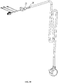
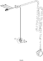
- the power supply line device further comprises a signal line 60, an end of the signal line 60 is provided with an environmental parameter identifier 62, and the signal line 60 is connected to the line body fixing structure 64, and the signal line 60 extends in the cabinet.
- the signal wire 60 and the line body 66 pass through the same end of the line body fixing structure 64, and then pass through the line body fixing structure 64 out of the other end of the line body fixing structure 64 and are integrated together.
- the environmental parameter identifier 62 may be set to be detachable or non-detachable.
- a seat body 68 is disposed at an end of the signal line 60, the environmental parameter identifier 62 is fixedly disposed on the seat body 68, and the seat body 68 is fixed on the household appliance.
- the environmental parameter identifier 62 is integrally integrated into the seat body 68 and cannot be detached.
- the environmental parameter identifier 62 comprises a temperature sensor for collecting an ambient temperature.
- the environmental parameter identifier 62 may also be configured to comprise a humidity sensor for collecting environmental humidity.
- the seat body 68 is detachably fixed to the household appliance by using a fastener such as a bolt, and the seat body 68 may be fixed to different positions on the outside the household appliance according to specific needs. Certainly, the seat body 68 may also be fixed on the household appliance by adhesion with an adhesive.
- FIG. 14 through FIG. 16 illustrate a sixth embodiment of the present invention.
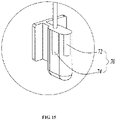
- the sixth embodiment differs from the fifth embodiment in that in this embodiment, an environmental parameter identifier 70 comprises both a temperature sensor 72 as well as a humidity sensor 74.
- Other configurations are the same as those in the fifth embodiment, and will not be described in detail any more here.
Landscapes
- Engineering & Computer Science (AREA)
- Chemical & Material Sciences (AREA)
- Combustion & Propulsion (AREA)
- Physics & Mathematics (AREA)
- Mechanical Engineering (AREA)
- Thermal Sciences (AREA)
- General Engineering & Computer Science (AREA)
- Microelectronics & Electronic Packaging (AREA)
- Details Of Connecting Devices For Male And Female Coupling (AREA)
Abstract
Description
- The present invention relates to a power supply line device and a household appliance.
- A refrigerator comprises a cabinet and a door for operably opening/closing the cabinet, the cabinet is provided with a temperature sensor for sensing an ambient temperature, the ambient temperature sensed by the temperature sensor is transferred to a control system, then the control system transfers a corresponding control instruction to a refrigeration system according to the ambient temperature, and the refrigeration system performs corresponding refrigeration according to a different control instruction. Usually, a signal line needs to be separately led out from the interior of the cabinet, and the temperature sensor is connected to an end of the signal line and disposed on the cabinet. Such an arrangement makes the structure very complicated, and the installation inconvenient. Furthermore, as being affected by the cabinet, the temperature sensed by the temperature sensor is not close to the ambient temperature, so that the control of the refrigeration of the refrigerator cannot be regulated completely according to the ambient temperature such that the refrigerator is not energy-saving enough.
- An object of the present invention is to provide a power supply line device and a household appliance, which are not only simple in structure, but also collect more accurate environmental parameters.
- To achieve one of the above objects, an embodiment of the present invention provides a power supply line device for powering a household appliance. The power supply line device comprises a line body, a plug disposed at one end of the line body, and a line body fixing structure disposed at the other end of the line body away from the plug, wherein the line body fixing structure is used to fix the line body to the household appliance, wherein the power supply line device further comprises an environmental parameter identifier which is used to collect environmental parameters outside the household appliance.
- As a further improvement of the embodiment of the present invention, the environmental parameter identifier is disposed on the line body.
- As a further improvement of the embodiment of the present invention, the environmental parameter identifier is disposed adjacent to the plug.
- As a further improvement of the embodiment of the present invention, the environmental parameter identifier is disposed adjacent to the line body fixing structure.
- As a further improvement of the embodiment of the present invention, the environmental parameter identifier is detachably disposed on the line body.
- As a further improvement of the embodiment of the present invention, the line body is provided with an accommodating space, and the line body is provided with a signal interface; when the environmental parameter identifier is mounted in the accommodating space, the environmental parameter identifier is interfaced with the signal interface to perform signal transmission.
- As a further improvement of the embodiment of the present invention, the power supply line device further comprises a signal line, an end of the signal line is provided with the environmental parameter identifier, and the signal line is connected to the line body fixing structure.
- As a further improvement of the embodiment of the present invention, the environmental parameter identifier comprises a temperature sensor.
- As a further improvement of the embodiment of the present invention, the environmental parameter identifier comprises a humidity sensor.
- To achieve one of the above objects, an embodiment of the present invention further provides a household appliance comprising a cabinet and the power supply line device according to any of the above technical solutions, the line body fixing structure is fixed to the cabinet, and the environmental parameter identifier is located outside the cabinet.
- As compared with the prior art, the present invention has the following advantageous effects: since the power supply line device for power supply is provided with the environmental parameter identifier which may collect environmental parameters such as ambient temperature and/or ambient humidity, it is unnecessary to separately provide corresponding signal lines and the environmental parameter identifier and mounting structures, which makes the structure simpler and convenient to mount. In addition, the collected environmental parameters are more accurate.
- An object of the present invention is to further provide a power supply line device and a household appliance, which are not only simple in structure, but also collect more accurate environmental parameters.
- To achieve one of the above objects, an embodiment of the present invention provides a power supply line device for powering a household appliance. The power supply line device comprises a line body, a plug disposed at one end of the line body, and a line body fixing structure disposed at the other end of the line body away from the plug, wherein the line body fixing structure is used to fix the line body to the household appliance, wherein the power supply line device further comprises an environmental parameter identifier which is disposed undetachably and used to collect environmental parameters outside the household appliance.
- As a further improvement of the embodiment of the present invention, the line body comprises a power supply lead wire and a protective sleeve wrapping the power supply lead wire, and the environmental parameter identifier is wrapped in the protective sleeve.
- As a further improvement of the embodiment of the present invention, the environmental parameter identifier is disposed adjacent to the plug.
- As a further improvement of the embodiment of the present invention, the environmental parameter identifier is disposed adjacent to the line body fixing structure.
- As a further improvement of the embodiment of the present invention, the power supply line device further comprises a signal line, an end of the signal line is provided with the environmental parameter identifier, and the signal line is connected to the line body fixing structure.
- As a further improvement of the embodiment of the present invention, a seat body is disposed at an end of the signal line, the environmental parameter identifier is fixedly disposed on the seat body, and the seat body is fixed on the household appliance.
- As a further improvement of the embodiment of the present invention, the environmental parameter identifier comprises a temperature sensor and/or a humidity sensor.
- To achieve one of the above objects, another embodiment of the present invention further provides a household appliance comprising a cabinet and a power supply line device for powering the household appliance, the power supply line device comprises a line body, a plug disposed at one end of the line body, and a line body fixing structure disposed at the other end of the line body away from the plug, wherein the line body fixing structure is used to fix the line body to the household appliance, wherein the power supply line device further comprises an environmental parameter identifier which is disposed undetachably and used to collect environmental parameters outside the household appliance.
- As a further improvement of the embodiment of the present invention, the line body comprises a power supply lead wire and a protective sleeve wrapping the power supply lead wire, and the environmental parameter identifier is wrapped in the protective sleeve.
- As a further improvement of the embodiment of the present invention, the power supply line device further comprises a signal line, an end of the signal line is provided with the environmental parameter identifier, and the signal line is connected to the line body fixing structure and extends into the cabinet.
- As compared with the prior art, the present invention has the following advantageous effects: since the power supply line device for power supply is provided with the environmental parameter identifier which may collect environmental parameters such as ambient temperature and/or ambient humidity, it is unnecessary to separately provide corresponding signal lines and environmental parameter identifier and mounting structures, which makes the structure simpler and convenient to mount. In addition, the collected environmental parameters are more accurate.
-
-
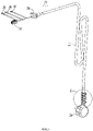
FIG. 1 is a perspective view of a power supply line device in a first embodiment of the present invention; -
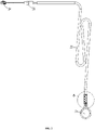
FIG. 2 is a front view of the power supply line device inFIG. 1 ; -
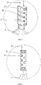
FIG. 3 is a partially-enlarged view of location A inFIG. 1 ; -
FIG. 4 is a partially-enlarged view of location B inFIG. 2 ; -
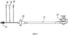
FIG. 5 is a top view of the power supply line device inFIG. 1 ; -
FIG. 6 is a perspective view of a power supply line device in a second embodiment of the present invention; -
FIG. 7 is a front view of the power supply line device inFIG. 6 ; -
FIG. 8 is a perspective view of a power supply line device in a third embodiment of the present invention; -
FIG. 9 is a front view of the power supply line device inFIG. 8 ; -
FIG. 10 is a perspective view of a power supply line device in a fourth embodiment of the present invention; -
FIG. 11 is a front view of the power supply line device inFIG. 10 ; -
FIG. 12 is a perspective view of a power supply line device in a fifth embodiment of the present invention; -
FIG. 13 is a front view of the power supply line device inFIG. 12 ; -
FIG. 14 is a perspective view of a power supply line device in a sixth embodiment of the present invention; -
FIG. 15 is a partially-enlarged view of location C inFIG. 14 ; -
FIG. 16 is a left view of the power supply line device ofFIG. 14 . - The present invention will be described in detail in conjunction with embodiments shown in the figures. However, the embodiments are not intended to limit the present invention. Structural, methodogical or function variations made by those having ordinary skill in the art according to these embodiments are all comprised in the protection scope of the present invention.
- In the description of specific embodiments of the present invention, terms indicating orientational or positional relationship such as "up", "down", "front", "rear", "left", "right", "vertical", "horizontal", "bottom", "in" and "out" is orientational or positional relationship based on what is shown in the figures, or the terms are used to describe mutual positional relationship of components in the vertical, perpendicular or gravitational direction, and the vertical direction refers to the up-down direction of the paper shown in the figures; "in" and "out" usually refer to the inside and outside of the cavity relative to the cavity.
- As shown in
FIG 1 through FIG. 5 , a first embodiment of the present invention discloses a household appliance, and the household appliance in the present embodiment may be any household appliance that needs a powersupply line device 20, for example, a refrigerator, a freezer, a washing machine, an air conditioner, microwave or oven etc. Preferably, the household appliance is any type of smart/intelligent household appliance. Specifically, the household appliance is a refrigerator in the present embodiment. - The household appliance comprises a cabinet having a chamber, and the chamber may be divided into different numbers of compartments as needed. The present invention further discloses a power
supply line device 20 for powering the household appliance. One end of the powersupply line device 20 extends into the cabinet, and the other end of the powersupply line device 20 is connected to an external power supply. - The power
supply line device 20 comprises aline body 22, aplug 24 disposed at one end of theline body 22, and a linebody fixing structure 26 disposed at the other end of theline body 22 away from theplug 24, wherein the linebody fixing structure 26 is used to fix theline body 22 to the household appliance. Specifically, the linebody fixing structure 26 is used to fix theline body 22 to the cabinet of the household appliance. - The power
supply line device 20 further comprises anenvironmental parameter identifier 28 which is used to collect environmental parameters outside the household appliance. The refrigerator further comprises a control system and a refrigeration system connected with the control system. The environmental parameters collected by theenvironmental parameter identifier 28 are transmitted to the control system, and the control system receives and analyzes the environmental parameters, and then generates corresponding control instructions according to different environmental parameters. The above control instructions are transmitted to the refrigeration system, and the refrigeration system performs corresponding refrigeration or other operations according to different control instructions. - In the preferred embodiment, since the power
supply line device 20 for power supply is provided with theenvironmental parameter identifier 28 which may collect environmental parameters such as ambient temperature and/or ambient humidity, it is unnecessary to separately provide corresponding signal lines and theenvironmental parameter identifier 28 and corresponding mounting structures, which makes the structure simpler and convenient to mount. In addition, theenvironmental parameter identifier 28 is not affected by the temperature of the cabinet, and the collected environmental parameters really reflect the environment outside the cabinet, so that the collected environmental parameters are more accurate. As a result, the control system can perform specific control better according to the external environment. - The line
body fixing structure 26 is fixed to the cabinet, and theenvironmental parameter identifier 28 is located outside the cabinet. Usually, a fixing hole is provided on the cabinet, and theline body 22 passes through the fixing hole. In order to make the affixation of theline body 22 firmer, part of the linebody fixing structure 26 may extend into the fixing hole. Certainly, the linebody fixing structure 26 may also be arranged to be completely located outside the fixing hole. A detachable fastening structure such as a bolt may be used to fix the linebody fixing structure 26 to the cabinet. Certainly, the linebody fixing structure 26 may also be adhered to the outside of the cabinet by using an adhesive. The term "detachable" usually means detaching a corresponding structure with or without a tool without damaging the component. - Furthermore, the
environmental parameter identifier 28 is disposed on theline body 22. Specifically, theenvironmental parameter identifier 28 is disposed adjacent to theplug 24. Such an arrangement makes theenvironmental parameter identifier 28 farther away from the cabinet, and the collected environmental parameters are more accurate. Theenvironmental parameter identifier 28 comprises a temperature sensor and/or a humidity sensor. That is to say, theenvironmental parameter identifier 28 may be configured to include only one sensor for collecting one parameter, or configured to include a plurality of sensors for collecting two or more parameters. - The
environmental parameter identifier 28 is detachably disposed on theline body 22. Certainly, theenvironmental parameter identifier 28 may also be integrally integrated into the powersupply line device 20, i.e., theenvironmental parameter identifier 28 is set to be non-detachable, which will be described in detail in the following embodiments. Here, the term "non-detachable" here means that theenvironmental parameter identifier 28 cannot be detached with or without a tool without damaging the powersupply line device 20, that is to say, the powersupply line device 20 must be damaged if theenvironmental parameter identifier 28 is detached. - The
line body 22 is provided with an accommodating space, and theenvironmental parameter identifier 28 is accommodated in the accommodating space. Furthermore, theline body 22 is provided with a signal interface. When theenvironmental parameter identifier 28 is mounted in the accommodating space, theenvironmental parameter identifier 28 is interfaced with the signal interface to perform signal transmission. Furthermore, for the sake of safety and reliability, theline body 22 is provided with acover body 30 for at least partially covering theenvironmental parameter identifier 28. Thecover body 30 can be opened when theenvironmental parameter identifier 28 needs to be replaced, and thecover body 30 may cover theenvironmental parameter identifier 28 again after the replacement of theenvironmental parameter identifier 28 is completed. In the preferred embodiment, when thecover body 30 is opened, thecover body 30 is completely detached from theline body 22, that is, thecover body 30 is completely separated from theline body 22. After theenvironmental parameter identifier 28 is replaced duly, thecover body 30 may be mounted on theline body 22 again. Certainly, thecover body 30 may also be configured in a way that thecover body 30 is not separated from theline body 22 when thecover body 30 is opened, thecover body 30 has an open state and a closed state, and thecover body 30 may be operated to be movable between the open state and the closed state. When thecover body 30 is moved to the open state, theenvironmental parameter identifier 28 may be replaced. After the replacement is completed, thecover body 30 may be operated to move to the closed state. Preferably, thecover body 30 may be operatively rotated between the open state and the closed state, to achieve the transition between the open state and the closed state. - Furthermore, the
cover body 30 is snap-connected to theline body 22, thecover body 30 is an injection-molded member, thecover body 30 has a raised snap-fitting portion, and thecover body 30 is snap-fitted to theline body 22 by utilizing certain elasticity of thecover body 30 as the injection-molded member. In addition, in order to make theenvironmental parameter identifier 28 more sensitive and the collected parameters more accurate, thecover body 30 is provided with a plurality of throughholes 32. Specifically, the plurality of throughholes 32 are arranged at an interval in an extension direction of theline body 22. - The power
supply line device 20 further comprises asignal connector 34, thesignal connector 34 and theenvironmental parameter identifier 28 are located on both sides of the linebody fixing structure 26, theenvironmental parameter identifier 28 is electrically connected to thesignal connector 34, and thesignal connector 34 is pluggably connected to the control system. The powersupply line device 20 further comprises apositive terminal 36, anegative terminal 38 and aneutral terminal 40. -
FIG. 6 to FIG. 7 illustrate a second embodiment of the present invention. The second embodiment differs from the first embodiment in the specific position of an environmental parameter identifier 42. - In the embodiment, the environmental parameter identifier 42 is disposed adjacent to a line
body fixing structure 44. The environmental parameter identifier 42 is also detachably disposed on aline body 46, and provided with acover body 48 covering the environmental parameter identifier. The fixing manner of thecover body 48 is the same as the fixing manner in the first embodiment, and will not be described in detail any more here. - As shown in
FIG. 8 to FIG 9 , a third embodiment of the present invention is different from the first embodiment in that theenvironmental parameter identifier 50 is set to be non-detachable. - In this embodiment, the
environmental parameter identifier 50 is set to be non-detachable, i.e., theenvironmental parameter identifier 50 cannot be detached without damaging all the parts. - Specifically, the
line body 52 comprises a power supply lead wire and a protective sleeve wrapping the power supply lead wire, and theenvironmental parameter identifier 50 is wrapped in the protective sleeve. The protective sleeve extends in an extension direction of the power supply lead wire and completely wraps the power supply lead wire, so theenvironmental parameter identifier 50 cannot be detached. Furthermore, theenvironmental parameter identifier 50 is disposed adjacent to theplug 54. Other configurations are the same as those in the first embodiment, and will not be described in detail any more here. -
FIG. 10 to FIG. 11 illustrate a fourth embodiment of the present invention. The fourth embodiment is the same as the third embodiment in that theenvironmental parameter identifier 56 is also set to be non-detachable, and theenvironmental parameter identifier 56 is wrapped in the protective sleeve. The fourth embodiment differs from the third embodiment in the specific position of theenvironmental parameter identifier 56. In the embodiment, theenvironmental parameter identifier 56 is disposed adjacent to the linebody fixing structure 58. -
FIG. 12 to FIG. 13 illustrate a fifth embodiment of the present invention. In the embodiment, the power supply line device further comprises asignal line 60, an end of thesignal line 60 is provided with anenvironmental parameter identifier 62, and thesignal line 60 is connected to the linebody fixing structure 64, and thesignal line 60 extends in the cabinet. In addition, thesignal wire 60 and theline body 66 pass through the same end of the linebody fixing structure 64, and then pass through the linebody fixing structure 64 out of the other end of the linebody fixing structure 64 and are integrated together. - The
environmental parameter identifier 62 may be set to be detachable or non-detachable. In this embodiment, aseat body 68 is disposed at an end of thesignal line 60, theenvironmental parameter identifier 62 is fixedly disposed on theseat body 68, and theseat body 68 is fixed on the household appliance. Specifically, theenvironmental parameter identifier 62 is integrally integrated into theseat body 68 and cannot be detached. Additionally, theenvironmental parameter identifier 62 comprises a temperature sensor for collecting an ambient temperature. Certainly, theenvironmental parameter identifier 62 may also be configured to comprise a humidity sensor for collecting environmental humidity. - The
seat body 68 is detachably fixed to the household appliance by using a fastener such as a bolt, and theseat body 68 may be fixed to different positions on the outside the household appliance according to specific needs. Certainly, theseat body 68 may also be fixed on the household appliance by adhesion with an adhesive. -
FIG. 14 through FIG. 16 illustrate a sixth embodiment of the present invention. The sixth embodiment differs from the fifth embodiment in that in this embodiment, anenvironmental parameter identifier 70 comprises both atemperature sensor 72 as well as ahumidity sensor 74. Other configurations are the same as those in the fifth embodiment, and will not be described in detail any more here. - It should be understood that although the description is described according to the embodiments, not every embodiment only comprises one independent technical solution, that such a description manner is only for the sake of clarity, that those skilled in the art should take the description as an integral part, and that the technical solutions in the embodiments may be suitably combined to form other embodiments understandable by those skilled in the art.
- The detailed descriptions set forth above are merely specific illustrations of feasible embodiments of the present invention, and are not intended to limit the scope of protection of the present invention. All equivalent embodiments or modifications that do not depart from the art spirit of the present invention should fall within the scope of protection of the present invention.
Claims (10)
- A power supply line device for powering a household appliance, the power supply line device comprising a line body, a plug disposed at one end of the line body, and a line body fixing structure disposed at the other end of the line body away from the plug, the line body fixing structure being used to fix the line body to the household appliance, wherein the power supply line device further comprises an environmental parameter identifier which is disposed undetachably and configured to collect environmental parameters outside the household appliance.
- The power supply line device according to claim 1, wherein the line body comprises a power supply lead wire and a protective sleeve wrapping the power supply lead wire, and the environmental parameter identifier is wrapped in the protective sleeve.
- The power supply line device according to claim 2, wherein the environmental parameter identifier is disposed adjacent to the plug.
- The power supply line device according to claim 2, wherein the environmental parameter identifier is disposed adjacent to the line body fixing structure.
- The power supply line device according to claim 1, wherein the power supply line device further comprises a signal line, an end of the signal line is provided with the environmental parameter identifier, and the signal line is connected to the line body fixing structure.
- The power supply line device according to claim 5, wherein a seat body is disposed at an end of the signal line, the environmental parameter identifier is fixedly disposed on the seat body, and the seat body is fixed on the household appliance.
- The power supply line device according to claim 1, wherein the environmental parameter identifier comprises a temperature sensor and/or a humidity sensor.
- A household appliance comprising a cabinet and a power supply line device for powering the household appliance, the power supply line device comprising a line body, a plug disposed at one end of the line body, and a line body fixing structure disposed at the other end of the line body away from the plug, the line body fixing structure being used to fix the line body to the household appliance, wherein the power supply line device further comprises an environmental parameter identifier which is disposed undetachably and configured to collect environmental parameters outside the household appliance.
- The household appliance according to claim 8, wherein the line body comprises a power supply lead wire and a protective sleeve wrapping the power supply lead wire, and the environmental parameter identifier is wrapped in the protective sleeve.
- The household appliance according to claim 8, wherein the power supply line device further comprises a signal line, an end of the signal line is provided with the environmental parameter identifier, and the signal line is connected to the line body fixing structure and extends into the cabinet.
Applications Claiming Priority (2)
| Application Number | Priority Date | Filing Date | Title |
|---|---|---|---|
| CN202010134161.5A CN111490412A (en) | 2020-03-02 | 2020-03-02 | Power Cord Sets and Home Appliances |
| PCT/CN2020/094079 WO2021174702A1 (en) | 2020-03-02 | 2020-06-03 | Power line device and household appliance |
Publications (2)
| Publication Number | Publication Date |
|---|---|
| EP4117124A1 true EP4117124A1 (en) | 2023-01-11 |
| EP4117124A4 EP4117124A4 (en) | 2023-08-09 |
Family
ID=71811598
Family Applications (1)
| Application Number | Title | Priority Date | Filing Date |
|---|---|---|---|
| EP20922529.1A Withdrawn EP4117124A4 (en) | 2020-03-02 | 2020-06-03 | POWER LINE DEVICE AND HOME APPLIANCE |
Country Status (3)
| Country | Link |
|---|---|
| EP (1) | EP4117124A4 (en) |
| CN (1) | CN111490412A (en) |
| WO (1) | WO2021174702A1 (en) |
Family Cites Families (18)
| Publication number | Priority date | Publication date | Assignee | Title |
|---|---|---|---|---|
| JP2001153537A (en) * | 1999-11-30 | 2001-06-08 | Toshiba Corp | refrigerator |
| US20080057767A1 (en) * | 2006-08-10 | 2008-03-06 | O'rourke Kevin | Electrical adaptor having an anchor |
| DE202007018307U1 (en) * | 2007-03-24 | 2008-06-12 | Harting Electric Gmbh & Co. Kg | Measuring device for connectors |
| CN102548056A (en) * | 2010-12-07 | 2012-07-04 | 李臣华 | Intelligent temperature-control electric heating pad |
| TWI523365B (en) * | 2011-01-28 | 2016-02-21 | 勝德國際研發股份有限公司 | Outlet |
| CN203103572U (en) * | 2012-12-31 | 2013-07-31 | 上海万卡信实业有限公司 | A high-sensitive high-voltage-resistant automobile air-conditioner wire harness |
| CN203481790U (en) * | 2013-01-29 | 2014-03-12 | 海尔集团公司 | Device for preventing power line temperature from being too high and electric appliance applying device |
| CN204012090U (en) * | 2014-06-30 | 2014-12-10 | 青岛经济技术开发区海尔热水器有限公司 | Power cord and water heater |
| WO2016081909A1 (en) * | 2014-11-21 | 2016-05-26 | Volex Plc | Electrical plug |
| US9564719B1 (en) * | 2014-12-12 | 2017-02-07 | Technology Research LLC. | Elevated temperature detection and interrupter circuit for power cable |
| US10158199B2 (en) * | 2015-11-25 | 2018-12-18 | Microsoft Technology Licensing, Llc | Power cord with in-line power control functionality |
| CN205488851U (en) * | 2016-01-19 | 2016-08-17 | 富士康(昆山)电脑接插件有限公司 | Power connector patch cable assembly |
| CN205752818U (en) * | 2016-05-23 | 2016-11-30 | 邰宝龙 | The electric power insert row that a kind of safety is high |
| US10240861B2 (en) * | 2016-10-19 | 2019-03-26 | Emanate Wireless, Inc. | Cold storage health monitoring system |
| CN108336613A (en) * | 2017-01-20 | 2018-07-27 | 胜德国际研发股份有限公司 | Electric device with environment sensing function |
| CN207116864U (en) * | 2017-07-07 | 2018-03-16 | 山东方寸山农业科技有限公司 | A kind of Intelligent socket with internet of things functional available for aquarium |
| CN107192416A (en) * | 2017-07-18 | 2017-09-22 | 杭州麦乐克科技股份有限公司 | Power line with temperature and humidity measuring function |
| CN207474827U (en) * | 2017-09-30 | 2018-06-08 | 广东美的厨房电器制造有限公司 | Power cord and the household electrical appliance for being provided with the power cord |
-
2020
- 2020-03-02 CN CN202010134161.5A patent/CN111490412A/en active Pending
- 2020-06-03 EP EP20922529.1A patent/EP4117124A4/en not_active Withdrawn
- 2020-06-03 WO PCT/CN2020/094079 patent/WO2021174702A1/en not_active Ceased
Also Published As
| Publication number | Publication date |
|---|---|
| EP4117124A4 (en) | 2023-08-09 |
| WO2021174702A1 (en) | 2021-09-10 |
| CN111490412A (en) | 2020-08-04 |
Similar Documents
| Publication | Publication Date | Title |
|---|---|---|
| KR101423471B1 (en) | Dishwasher including accessible control unit and method thereof | |
| EP2824406B1 (en) | Refrigerator | |
| US20040070497A1 (en) | Cupboard monitoring device | |
| CN104511319A (en) | Apparatus for environmental test | |
| JP3730604B2 (en) | Indoor unit of air conditioner | |
| EP4117124A1 (en) | Power line device and household appliance | |
| EP4117125A1 (en) | Power line device and household appliance | |
| EP4117126A1 (en) | Power line device and combination system having at least one household appliance | |
| EP3616572B1 (en) | Cooking appliance | |
| JP2009210135A (en) | Outside air temperature sensor mounting tool, outdoor unit comprising mounting tool, and air conditioner comprising outdoor unit | |
| CN1930432A (en) | Refrigeration device | |
| CN208108291U (en) | Air conditioner indoor unit and air conditioner | |
| EP4517178A1 (en) | A door for a home appliance | |
| CN211829451U (en) | Power cord device and combined system with at least one household appliance | |
| CA3069584C (en) | Intelligent power line and home appliance provided with same | |
| EP3931905A1 (en) | Antenna for soil sensors | |
| CN105157305B (en) | Refrigerator | |
| CN115371143A (en) | Outdoor unit and heat exchange equipment | |
| CN209623040U (en) | The mounting structure of air conditioner indoor unit Temperature Humidity Sensor | |
| CN210534572U (en) | Electronic speed regulator and remote control device | |
| JP6334110B2 (en) | Washing machine | |
| US20250081373A1 (en) | Doors for home appliance and home appliance including the same | |
| EP4545860A1 (en) | Home appliance | |
| CN113124594A (en) | Electric control element protective cover and refrigerator | |
| JP3650502B2 (en) | Air conditioner sensor stopper |
Legal Events
| Date | Code | Title | Description |
|---|---|---|---|
| STAA | Information on the status of an ep patent application or granted ep patent |
Free format text: STATUS: THE INTERNATIONAL PUBLICATION HAS BEEN MADE |
|
| PUAI | Public reference made under article 153(3) epc to a published international application that has entered the european phase |
Free format text: ORIGINAL CODE: 0009012 |
|
| STAA | Information on the status of an ep patent application or granted ep patent |
Free format text: STATUS: REQUEST FOR EXAMINATION WAS MADE |
|
| 17P | Request for examination filed |
Effective date: 20220330 |
|
| AK | Designated contracting states |
Kind code of ref document: A1 Designated state(s): AL AT BE BG CH CY CZ DE DK EE ES FI FR GB GR HR HU IE IS IT LI LT LU LV MC MK MT NL NO PL PT RO RS SE SI SK SM TR |
|
| DAV | Request for validation of the european patent (deleted) | ||
| DAX | Request for extension of the european patent (deleted) | ||
| A4 | Supplementary search report drawn up and despatched |
Effective date: 20230711 |
|
| RIC1 | Information provided on ipc code assigned before grant |
Ipc: H01R 24/30 20110101ALI20230705BHEP Ipc: F25D 29/00 20060101ALI20230705BHEP Ipc: F25D 23/00 20060101ALI20230705BHEP Ipc: H01R 31/06 20060101ALI20230705BHEP Ipc: H01R 27/00 20060101ALI20230705BHEP Ipc: H01R 13/73 20060101ALI20230705BHEP Ipc: H01R 13/66 20060101AFI20230705BHEP |
|
| STAA | Information on the status of an ep patent application or granted ep patent |
Free format text: STATUS: EXAMINATION IS IN PROGRESS |
|
| 17Q | First examination report despatched |
Effective date: 20250805 |
|
| STAA | Information on the status of an ep patent application or granted ep patent |
Free format text: STATUS: THE APPLICATION HAS BEEN WITHDRAWN |
|
| 18W | Application withdrawn |
Effective date: 20251125 |