EP4116773A1 - Control method of driving apparatus, driving apparatus, lithography apparatus, and method of manufacturing article - Google Patents
Control method of driving apparatus, driving apparatus, lithography apparatus, and method of manufacturing article Download PDFInfo
- Publication number
- EP4116773A1 EP4116773A1 EP22181193.8A EP22181193A EP4116773A1 EP 4116773 A1 EP4116773 A1 EP 4116773A1 EP 22181193 A EP22181193 A EP 22181193A EP 4116773 A1 EP4116773 A1 EP 4116773A1
- Authority
- EP
- European Patent Office
- Prior art keywords
- stator
- driving
- coils
- linear motor
- mover
- Prior art date
- Legal status (The legal status is an assumption and is not a legal conclusion. Google has not performed a legal analysis and makes no representation as to the accuracy of the status listed.)
- Pending
Links
Images




Classifications
-
- G—PHYSICS
- G03—PHOTOGRAPHY; CINEMATOGRAPHY; ANALOGOUS TECHNIQUES USING WAVES OTHER THAN OPTICAL WAVES; ELECTROGRAPHY; HOLOGRAPHY
- G03F—PHOTOMECHANICAL PRODUCTION OF TEXTURED OR PATTERNED SURFACES, e.g. FOR PRINTING, FOR PROCESSING OF SEMICONDUCTOR DEVICES; MATERIALS THEREFOR; ORIGINALS THEREFOR; APPARATUS SPECIALLY ADAPTED THEREFOR
- G03F7/00—Photomechanical, e.g. photolithographic, production of textured or patterned surfaces, e.g. printing surfaces; Materials therefor, e.g. comprising photoresists; Apparatus specially adapted therefor
- G03F7/70—Microphotolithographic exposure; Apparatus therefor
- G03F7/70691—Handling of masks or workpieces
- G03F7/70716—Stages
- G03F7/70725—Stages control
-
- G—PHYSICS
- G03—PHOTOGRAPHY; CINEMATOGRAPHY; ANALOGOUS TECHNIQUES USING WAVES OTHER THAN OPTICAL WAVES; ELECTROGRAPHY; HOLOGRAPHY
- G03F—PHOTOMECHANICAL PRODUCTION OF TEXTURED OR PATTERNED SURFACES, e.g. FOR PRINTING, FOR PROCESSING OF SEMICONDUCTOR DEVICES; MATERIALS THEREFOR; ORIGINALS THEREFOR; APPARATUS SPECIALLY ADAPTED THEREFOR
- G03F7/00—Photomechanical, e.g. photolithographic, production of textured or patterned surfaces, e.g. printing surfaces; Materials therefor, e.g. comprising photoresists; Apparatus specially adapted therefor
- G03F7/70—Microphotolithographic exposure; Apparatus therefor
- G03F7/70691—Handling of masks or workpieces
- G03F7/70758—Drive means, e.g. actuators, motors for long- or short-stroke modules or fine or coarse driving
-
- G—PHYSICS
- G03—PHOTOGRAPHY; CINEMATOGRAPHY; ANALOGOUS TECHNIQUES USING WAVES OTHER THAN OPTICAL WAVES; ELECTROGRAPHY; HOLOGRAPHY
- G03F—PHOTOMECHANICAL PRODUCTION OF TEXTURED OR PATTERNED SURFACES, e.g. FOR PRINTING, FOR PROCESSING OF SEMICONDUCTOR DEVICES; MATERIALS THEREFOR; ORIGINALS THEREFOR; APPARATUS SPECIALLY ADAPTED THEREFOR
- G03F7/00—Photomechanical, e.g. photolithographic, production of textured or patterned surfaces, e.g. printing surfaces; Materials therefor, e.g. comprising photoresists; Apparatus specially adapted therefor
- G03F7/70—Microphotolithographic exposure; Apparatus therefor
- G03F7/70691—Handling of masks or workpieces
- G03F7/70716—Stages
-
- H—ELECTRICITY
- H02—GENERATION; CONVERSION OR DISTRIBUTION OF ELECTRIC POWER
- H02K—DYNAMO-ELECTRIC MACHINES
- H02K41/00—Propulsion systems in which a rigid body is moved along a path due to dynamo-electric interaction between the body and a magnetic field travelling along the path
- H02K41/02—Linear motors; Sectional motors
-
- H—ELECTRICITY
- H02—GENERATION; CONVERSION OR DISTRIBUTION OF ELECTRIC POWER
- H02P—CONTROL OR REGULATION OF ELECTRIC MOTORS, ELECTRIC GENERATORS OR DYNAMO-ELECTRIC CONVERTERS; CONTROLLING TRANSFORMERS, REACTORS OR CHOKE COILS
- H02P25/00—Arrangements or methods for the control of AC motors characterised by the kind of AC motor or by structural details
- H02P25/02—Arrangements or methods for the control of AC motors characterised by the kind of AC motor or by structural details characterised by the kind of motor
- H02P25/06—Linear motors
-
- H—ELECTRICITY
- H02—GENERATION; CONVERSION OR DISTRIBUTION OF ELECTRIC POWER
- H02P—CONTROL OR REGULATION OF ELECTRIC MOTORS, ELECTRIC GENERATORS OR DYNAMO-ELECTRIC CONVERTERS; CONTROLLING TRANSFORMERS, REACTORS OR CHOKE COILS
- H02P25/00—Arrangements or methods for the control of AC motors characterised by the kind of AC motor or by structural details
- H02P25/02—Arrangements or methods for the control of AC motors characterised by the kind of AC motor or by structural details characterised by the kind of motor
- H02P25/06—Linear motors
- H02P25/064—Linear motors of the synchronous type
-
- H—ELECTRICITY
- H02—GENERATION; CONVERSION OR DISTRIBUTION OF ELECTRIC POWER
- H02P—CONTROL OR REGULATION OF ELECTRIC MOTORS, ELECTRIC GENERATORS OR DYNAMO-ELECTRIC CONVERTERS; CONTROLLING TRANSFORMERS, REACTORS OR CHOKE COILS
- H02P25/00—Arrangements or methods for the control of AC motors characterised by the kind of AC motor or by structural details
- H02P25/16—Arrangements or methods for the control of AC motors characterised by the kind of AC motor or by structural details characterised by the circuit arrangement or by the kind of wiring
- H02P25/22—Multiple windings; Windings for more than three phases
Definitions
- the present invention relates to a control method of a driving apparatus, the driving apparatus, a lithography apparatus, and a method of manufacturing an article.
- a lithography apparatus As a lithography apparatus used in manufacturing semiconductor devices or the like, a lithography apparatus is known that uses, as a driving apparatus which drives a stage holding an original and/or a substrate or the like, a multi-phase linear motor that selectively switches the coil to be energized in accordance with the position of a mover.
- the multi-phase excitation driving type linear motor When driving the stage, the multi-phase excitation driving type linear motor simultaneously applies, to the coils of two phases whose phase angles of the magnetic flux densities are separated by 90°, currents corresponding to the respective magnetic flux densities (performs two-phase excitation). With this, it is possible to obtain a constant thrust with reduced thrust unevenness.
- Japanese Patent Laid-Open No. 2006-67761 proposes a method of positioning a stator such that the electrical phase angle of the linear motor upon accelerating or decelerating a driven object is set in a predetermined state (for example, such that the phase angle and current are uniform between the coils of two phases).
- the present invention provides, for example, a technique advantageous in reducing a local deterioration in the stator of a linear motor.
- the present invention in its first aspect provides a control method of a driving apparatus as specified in claims 1 to 8.
- the present invention in its second aspect provides a driving apparatus as specified in claim 9.
- the present invention in its third aspect provides a lithography apparatus as specified in claim 10.
- the present invention in its fourth aspect provides a method of manufacturing an article as specified in claim 11.
- the driving apparatus and the control method thereof according to the present invention are applied to an exposure apparatus that exposes a substrate to transfer the pattern of an original (mask) onto the substrate.
- the present invention is not limited to this.
- the driving apparatus and the control method thereof according to the present invention are also applicable to another lithography apparatus such as an imprint apparatus that forms a pattern of an imprint material on a substrate using a mold.
- the driving apparatus and the control method thereof according to the present invention are applicable not only to the lithography apparatus but also to an apparatus that performs a driving process of a target object (object to be driven).
- Fig. 1 is a schematic view showing an arrangement example of an exposure apparatus 10 of this embodiment.
- the exposure apparatus 10 of this embodiment can include, for example, an illumination optical system 12, an original stage 13 that can move while holding an original M such as a mask, a projection optical system 14, a substrate stage 15 that can move while holding a substrate S such as a wafer, and a controller 16.
- the controller 16 is formed by, for example, a computer including a CPU (Central Processing Unit), a memory, and the like, and controls an exposure process of the substrate S by controlling the respective units of the exposure apparatus 10.
- a step-and-scan exposure apparatus (so-called scanning exposure apparatus) will be illustrated and described as the exposure apparatus 10.
- the illumination optical system 12 shapes light emitted from a light source 11 into, for example, band-like or arcuate slit-shaped light, and illuminates a portion of the original M with this slit-shaped light.
- the light transmitted through the portion of the original M enters the projection optical system 14 as pattern light reflecting the pattern of the portion of the original M.
- the projection optical system 14 has a predetermined projection magnification, and projects the pattern image of the original M onto the substrate S (more specifically, the resist on the substrate) by using the pattern light.
- the original M and the substrate S are held by the original stage 13 and the substrate stage 15, respectively, and are arranged in optically conjugate positions (the object plane and image plane of the projection optical system 14) via the projection optical system 14.
- the controller 16 relatively scans, in a predetermined scanning direction, the original stage 13 and substrate stage 15 in synchronism with each other at a velocity ratio matching the projection magnification of the projection optical system 14. With this, an exposure process of exposing the substrate S to transfer the pattern of the original M onto the substrate can be performed. The exposure process can be performed on each of a plurality of shot regions in the substrate.
- Fig. 2 is a schematic view showing an arrangement example of the driving apparatus 20 of this embodiment, and shows an example in which the original stage 13 is driven as a target object to be driven.
- the original stage 13 is levitated from a stage base 28 at a minute interval by a gas bearing (not shown), and is driven in the Y-axis direction by a linear motor 21 to be described later.
- the driving apparatus 20 may be used to drive the substrate stage 15 in addition to the original stage 13.
- the driving apparatus 20 of this embodiment includes the linear motor 21 and a controller 25.
- the linear motor 21 can include a stator 22 in which a plurality of coils 22a are arrayed along the driving direction (Y-axis direction in Fig. 2 ) of the original stage 13, and a mover 23 provided with the original stage 13.
- the controller 25 is formed by, for example, a computer including a CPU, a memory, and the like, and controls energization of the stator 22 (the plurality of coils 22a) of the linear motor 21 to control driving of the substrate stage 15 by the linear motor 21.
- the controller 25 may be formed as a part of the controller 16 of the exposure apparatus 10 described above, or may be formed as a separate body from the controller 16.
- the position of the original stage 13 in the Y-axis direction can be measured by a laser interferometer 26, and the position of the stator 22 in the Y-axis direction can be measured by a laser interferometer 27.
- the controller 25 can control the position of the original stage 13 in the Y-axis direction based on the measurement result of the laser interferometer 26, and control the position of the stator 22 in the Y-axis direction based on the measurement result of the laser interferometer 27.
- the linear motor 21 in the driving apparatus 20 of this embodiment can be formed as a multi-phase excitation driving type linear motor (to be sometimes described as the multi-phase linear motor 21 hereinafter).
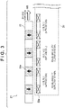
- Fig. 3 shows an arrangement example of a part of the multi-phase linear motor 21.
- the plurality of coils 22a in the stator 22 are arranged by alternately arranging the A-phase (first phase) coil and the B-phase (second phase) coil.
- the mover 23 includes a plurality of permanent magnets 23a arranged in the Halbach array which forms a magnetic flux density waveform.
- the plurality of permanent magnets 23a are arrayed along the array direction of the plurality of coils 22a in the stator 22.
- a current corresponding to the phase angle decided by the relative position between the plurality of coils 22a of the stator 22 and the permanent magnet 23a of the mover 23 is supplied to the plurality of coils 22a.
- Fig. 4 shows an example of the magnetic flux density distribution passing through the coils of respective phases with respect to the position of the mover 23 in the multi-phase linear motor 21.
- a current proportional to cos(X) is supplied to the A-phase coil.
- the magnetic flux density passing through the B-phase coil in which the phase angle of the magnetic flux density is shifted 90° with respect to that of the A-phase coil, is represented by sin(X).
- a current proportional to sin(X) is supplied to the B-phase coil.
- the driving apparatus 20 described above repeatedly performs, for each exposure process, a driving process of driving the original stage 13 in a predetermined range R by the multi-phase linear motor 21.
- a driving process for example, when driving the mover 23 in the predetermined range R from the point A to the point B as shown in Fig. 5 , a current can be supplied to the coil 22a of the stator 22 at the point A where the mover 23 is accelerated and the point B where the mover 23 is decelerated.
- the point A may be understood as the acceleration point (acceleration section) where the mover 23 is accelerated
- the point B may be understood as the deceleration point (deceleration section) where the mover 23 is decelerated.
- the predetermined range R is the driving range of the original stage 13 set in advance to drive the original stage 13 in scanning exposure, and may be understood as the driving range of the mover 23 in the multi-phase linear motor 21.
- the driving apparatus 20 of this embodiment includes a moving mechanism 24 (see Fig. 3 ) that moves the stator 22 in the driving direction (Y-axis direction) of the mover 23. At an arbitrary timing (predetermined timing), the position of the stator 22 with respect to the predetermined range R is changed by the moving mechanism 24.
- the output ratios of the plurality of coils 22a in the driving process after the arbitrary timing are determined so as to be changed with respect to the output ratios of the plurality of coils 22a before the arbitrary timing.
- the process to be sometimes referred to as the moving process of the stator 22 hereinafter
- it is possible to reduce the bias of the current load on the coil 22a at the acceleration point and/or the deceleration point, and reduce the local deterioration in the stator 22 (the plurality of coils 22a).
- the moving mechanism 24 includes, for example, an electric actuator, and can move the stator 22 under the control of the controller 25.
- the controller 25 supplies a signal to the moving mechanism 24 at an arbitrary timing
- the position of the stator 22 with respect to the predetermined range R can be automatically changed.
- the moving mechanism 24 may include, for example, a manual actuator such as a ball screw.
- the position of the stator 22 with respect to the predetermine range R can be manually changed. Note that in the following description, an example will be described in which an electric actuator is provided in the moving mechanism 24 and the moving mechanism 24 is controlled by the controller 25.
- the arbitrary timing can be, for example, a timing in a period between a plurality of driving processes (exposure processes).
- the arbitrary timing may also be a timing at which the number of driving operations of the original stage 13 serving as the target object to be driven (this may be understood as the number of exposure processes) reaches a preset threshold value.
- the arbitrary timing may be a timing at which the value of each of various kinds of sensors provided in the driving apparatus 20 (exposure apparatus 10), for example, the value detected by a temperature sensor and/or a pressure sensor reaches a preset threshold value.
- the value of each of the various kinds of sensors can include, for example, the temperature of the linear motor 21 detected by the temperature sensor and/or the internal pressure of the exposure apparatus 10 detected by the pressure sensor.
- the arbitrary timing may be a timing at which the electric characteristic of at least one coil of the plurality of coils 22a in the stator 22 reaches a preset threshold value.
- the electric characteristic can include at least one of the resistance value, the voltage value, the current value, and the inductance value of the coil.
- the arbitrary timing may be a timing at which the difference between the measurement value indicating the driving state of the original stage 13 and a target value (set value) reaches a preset threshold value.
- the driving state can include at least one of the velocity, the acceleration, and the position of the original stage 13 in the driving process.
- Figs. 6A to 7B are views for explaining an example of the moving process of the stator 22, and show the positional relationship between the stator 22 (coils 22a) and the mover 23 (permanent magnets 23a) at each of the acceleration point and the deceleration point.
- Figs. 6A and 6B show the positional relationship between the stator 22 and the mover 23 before performing the moving process of the stator 22
- Figs. 7A and 7B show the positional relationship between the stator 22 and the mover 23 after performing the moving process of the stator 22.
- Figs. 6A to 7B show a case in which the multi-phase linear motor 21 performs two-phase excitation (A-phase and B-phase).
- Figs. 6A and 6B show an example of the positional relationship between the stator 22 (coils 22a) and the mover 23 (permanent magnets 23a) before performing the moving process of the stator 22.
- Fig. 6A shows the positional relationship between the stator 22 and the mover 23 at the point A where the mover 23 is accelerated in the predetermined range R
- Fig. 6B shows the positional relationship between the stator 22 and the mover 23 at the point B where the mover 23 is decelerated in the predetermined range R.
- the A-phase coil and B-phase coil used to accelerate the mover 23 at the point A are the coil No. 1 and coil No. 2, respectively.
- the coil No. 1 A-phase coil
- ⁇ maximum driving current value
- the maximum current is applied (supplied) to the coil No. 1.
- the coil No. 2 B-phase coil
- ⁇ ⁇ cos(270°) 0 holds.
- no current is applied (supplied) to the coil No. 2.
- the A-phase coil and B-phase coil used to decelerate (stop) the mover 23 at the point B are the coil No. 6 and coil No. 7, respectively.
- the position of the stator 22 with respect to the predetermine range R is changed by the moving mechanism 24 at an arbitrary timing and, in accordance with the change of the position of the stator 22, the output ratios of the plurality of coils 22a in the driving process are changed.
- Figs. 7A and 7B shows an example of the positional relationship between the stator 22 (coils 22a) and the mover 23 (permanent magnets 23a) after performing the moving process of the stator 22.
- Fig. 7A shows the positional relationship between the stator 22 and the mover 23 at the point A where the mover 23 is accelerated in the predetermined range R
- Fig. 7B shows the positional relationship between the stator 22 and the mover 23 at the point B where the mover 23 is decelerated in the predetermined range R.
- the position of the stator 22 with respect to the predetermined range R is changed by the moving mechanism 24 such that the phase angle between the stator 22 and the mover 23 is changed by 90°, that is, the position of the stator 22 is changed by the distance corresponding to the phase angle of 90°.
- the distance corresponding to the phase angle of 90° may be understood as the distance of one pole dimension of the plurality of permanent magnets 23a in the mover 23, or may be understood as a distance of half the array pitch of the plurality of permanent magnets 23a.
- the change amount of the position of the stator 22 by the moving mechanism 24 is not limited to the distance corresponding to the phase angle of 90° as long as the output ratios of the plurality of coils 22a in the acceleration and/or deceleration of the mover 23 change.
- the A-phase coil and B-phase coil used to accelerate the mover 23 at the point A are the coil No. 1 and coil No. 2, respectively.
- the coil No. 1 A-phase coil
- ⁇ ⁇ cos(90°) 0 holds.
- no current is applied (supplied) to the coil No. 1.
- the coil No. 2 B-phase coil
- ⁇ ⁇ cos(360°) ⁇ holds.
- the maximum current is applied (supplied) to the coil No. 2. That is, in the example shown in Fig.
- phase angle of the coil No. 1 and the phase angle of the coil No. 2 are interchanged as compared with the example shown in Fig. 6A , so that the output ratios of the plurality coils 22a in the stator 22 can be changed.
- the A-phase coil and B-phase coil used to decelerate (stop) the mover 23 at the point B are the coil No. 6 and coil No. 7, respectively.
- the phase angle of the coil No. 1 and the phase angle of the coil No. 2 after the moving process of the stator 22 are interchanged with respect to those before the moving process.
- the output ratios of the plurality of coils 22a in the stator 22 after the moving process can be determined so as to be changed with respect to those before the moving process. Accordingly, the current load time of the coil No. 1 and that of the coil No. 2 are averaged. This can decrease the bias of the current load, so that the local deterioration in the stator 22 can be reduced.
- point B the deceleration point shown in Figs.
- the current load on the coil No. 6 is equal to the current load on the coil No. 7 both before and after the moving process of the stator 22. Accordingly, also at the deceleration point, the bias of the current load can be decreased, so that the local deterioration in the stator 22 can be reduced.
- the output ratios of the plurality of coils 22a at the deceleration point (point B) are not changed.
- the output ratios of the plurality of coils 22a at the deceleration point may be changed.
- the position of the stator 22 with respect to the predetermined range R may be changed by the moving mechanism 24 such that the output ratios of the plurality of coils 22a at the deceleration point (point B) are changed instead of or in addition to the acceleration point (point A).
- Fig. 8 is a flowchart illustrating an operation example of the driving apparatus 20 of this embodiment.
- the operation of the driving apparatus 20 in a case in which the driving apparatus 20 is applied to the exposure apparatus 10 described above will be described.
- Each step in the flowchart of Fig. 8 can be performed by the controller 25.
- step S11 the controller 25 performs the driving process of driving the original stage 13 by the multi-phase linear motor 21.
- This driving process may be understood to correspond to the exposure process on one shot region in the substrate S.
- step S12 the controller 25 determines whether to change the position of the stator 22, that is, whether to perform the moving process of the stator 22. For example, as has been described above, based on the number of driving operations of the original stage 13, the value of each of the various kinds of sensors, or the like, the controller 25 can determine whether it is the timing to perform the moving process of the stator 22. If it is determined that the moving process of the stator 22 is performed, the process advances to step S13. If it is determined that the moving process of the stator 22 is not performed, the process advances to step S14.
- step S13 the controller 25 performs the moving process of the stator 22 by changing the position of the stator 22 with respect to the predetermined range R by the moving mechanism 24.
- the controller 25 changes the position of the stator 22 by the moving mechanism 24 such that the output ratios of the plurality of coils 22a at the acceleration point and/or the deceleration point after the moving process of the stator 22 are changed with respect to those before the moving process.
- the output ratios of the plurality of coils 22a in the stator 22 are changed such that the mover 23 can be driven in the predetermined range R.
- step S14 the controller 25 determines whether to continue to perform the driving process, that is, whether the next driving process is performed.
- This step S14 may be understood as a step of determining whether there is a shot region to undergo the exposure process next.
- the shot region to undergo the exposure process next may be, for example, a shot region, among the plurality of shot regions in the substrate S, where the exposure process has not been performed, or may be a shot region of a substrate where the exposure process has not been performed in a lot including a plurality of the substrates S. If the next driving process is performed, the process advances to step S11. If the next driving process is not performed, the process is terminated. In this manner, the moving process of the stator 22 can be performed in a period between the driving process and the next driving process.
- the driving apparatus 20 of this embodiment changes the position of the stator 22 with respect to the predetermined range R by the moving mechanism 24 at an arbitrary timing. Then, in accordance with the change of the position of the stator 22, the output ratios of the plurality of coils 22a in the driving process after the arbitrary timing are determined so as to be changed with respect to the output ratios of the plurality of coils 22a before the arbitrary timing. With this process, it is possible to decrease the bias of the current loads on the plurality of coils 22a in the stator 22, so that the local deterioration in the stator 22 can be reduced.
- the two-phase excitation driving type linear motor is used as the multi-phase linear motor 21 in this embodiment, but the present invention is not limited to this. An excitation driving type linear motor of three or more phases may be used. Further, in this embodiment, a moving magnet type linear motor is used as the multi-phase linear motor 21, but a moving coil type linear motor may be used.
- a method of manufacturing an article according to the embodiment of the present invention is suitable for manufacturing an article, for example, a microdevice such as a semiconductor device or an element having a microstructure.
- the method of manufacturing an article according to the embodiment includes a step of forming a pattern on a substrate by using the above-described lithography apparatus (exposure apparatus), and a step of processing the substrate on which the pattern has been formed in the preceding step. Furthermore, this manufacturing method includes other well-known steps (for example, oxidization, deposition, vapor deposition, doping, planarization, etching, resist removal, dicing, bonding, and packaging, and the like).
- the method of manufacturing an article according to the embodiment is superior to a conventional method in at least one of the performance, quality, productivity, and production cost of the article.
- Embodiment(s) of the present invention can also be realized by a computer of a system or apparatus that reads out and executes computer executable instructions (e.g., one or more programs) recorded on a storage medium (which may also be referred to more fully as a 'non-transitory computer-readable storage medium') to perform the functions of one or more of the above-described embodiment(s) and/or that includes one or more circuits (e.g., application specific integrated circuit (ASIC)) for performing the functions of one or more of the above-described embodiment(s), and by a method performed by the computer of the system or apparatus by, for example, reading out and executing the computer executable instructions from the storage medium to perform the functions of one or more of the above-described embodiment(s) and/or controlling the one or more circuits to perform the functions of one or more of the above-described embodiment(s).
- computer executable instructions e.g., one or more programs
- a storage medium which may also be referred to more fully as
- the computer may comprise one or more processors (e.g., central processing unit (CPU), micro processing unit (MPU)) and may include a network of separate computers or separate processors to read out and execute the computer executable instructions.
- the computer executable instructions may be provided to the computer, for example, from a network or the storage medium.
- the storage medium may include, for example, one or more of a hard disk, a random-access memory (RAM), a read only memory (ROM), a storage of distributed computing systems, an optical disk (such as a compact disc (CD), digital versatile disc (DVD), or Blu-ray Disc (BD) TM ), a flash memory device, a memory card, and the like.
- the present invention provides a control method of a driving apparatus (20) that repeatedly performs a process of driving a target object (13, 15) in a predetermined range (R) by a linear motor (21), wherein the linear motor includes a stator (22) in which a plurality of coils (22a) are arrayed, and a mover (23) provided with the target object, the control method comprising: changing a position of the stator with respect to the predetermined range at an arbitrary timing; and determining, in accordance with the changed position of the stator, output ratios of the plurality of coils in the process.
Landscapes
- Physics & Mathematics (AREA)
- General Physics & Mathematics (AREA)
- Engineering & Computer Science (AREA)
- Power Engineering (AREA)
- Chemical & Material Sciences (AREA)
- Combustion & Propulsion (AREA)
- Electromagnetism (AREA)
- Exposure And Positioning Against Photoresist Photosensitive Materials (AREA)
- Control Of Linear Motors (AREA)
- Container, Conveyance, Adherence, Positioning, Of Wafer (AREA)
- Exposure Of Semiconductors, Excluding Electron Or Ion Beam Exposure (AREA)
Abstract
Description
- The present invention relates to a control method of a driving apparatus, the driving apparatus, a lithography apparatus, and a method of manufacturing an article.
- As a lithography apparatus used in manufacturing semiconductor devices or the like, a lithography apparatus is known that uses, as a driving apparatus which drives a stage holding an original and/or a substrate or the like, a multi-phase linear motor that selectively switches the coil to be energized in accordance with the position of a mover.
Japanese Patent Laid-Open No. 9-19178 - In the multi-phase linear motor as described above, when accelerating the stage, a current may be applied only to the coil of one phase out of the coils of two phases. In this case, the power load is concentrated only on the coil of one phase, and this leads to a remarkable temperature rise. Accordingly, the heat generation of the coil locally increases, and a performance deterioration or a reduction in life of the linear motor can occur.
Japanese Patent Laid-Open No. 2006-67761 - In the method described in
Japanese Patent Laid-Open No. 2006-67761 Japanese Patent Laid-Open No. 2006-67761 - The present invention provides, for example, a technique advantageous in reducing a local deterioration in the stator of a linear motor.
- The present invention in its first aspect provides a control method of a driving apparatus as specified in claims 1 to 8.
- The present invention in its second aspect provides a driving apparatus as specified in claim 9.
- The present invention in its third aspect provides a lithography apparatus as specified in
claim 10. - The present invention in its fourth aspect provides a method of manufacturing an article as specified in
claim 11. - Further features of the present invention will become apparent from the following description of exemplary embodiments with reference to the attached drawings.
-
-
Fig. 1 is a schematic view showing an arrangement example of an exposure apparatus; -
Fig. 2 is a schematic view showing an arrangement example of a driving apparatus; -
Fig. 3 is a schematic view showing an arrangement example of a part of a multi-phase linear motor; -
Fig. 4 is a graph showing an example of the magnetic flux density distribution passing through the coils of respective phases with respect to the position of the mover in the multi-phase linear motor; -
Fig. 5 is a view showing an example of driving the mover in a predetermined range in the multi-phase linear motor; -
Figs. 6A and 6B are views for explaining an example of the moving process of the stator; -
Figs. 7A and 7B are views for explaining the example of the moving process of the stator; and -
Fig. 8 is a flowchart illustrating an operation example of the driving apparatus. - Hereinafter, embodiments will be described in detail with reference to the attached drawings. Note, the following embodiments are not intended to limit the scope of the claimed invention. Multiple features are described in the embodiments, but limitation is not made an invention that requires all such features, and multiple such features may be combined as appropriate. Furthermore, in the attached drawings, the same reference numerals are given to the same or similar configurations, and redundant description thereof is omitted.
- In each embodiment described below, an example will be described in which the driving apparatus and the control method thereof according to the present invention are applied to an exposure apparatus that exposes a substrate to transfer the pattern of an original (mask) onto the substrate. However, the present invention is not limited to this. The driving apparatus and the control method thereof according to the present invention are also applicable to another lithography apparatus such as an imprint apparatus that forms a pattern of an imprint material on a substrate using a mold. Further, the driving apparatus and the control method thereof according to the present invention are applicable not only to the lithography apparatus but also to an apparatus that performs a driving process of a target object (object to be driven).
- The first embodiment according to the present invention will be described.
Fig. 1 is a schematic view showing an arrangement example of anexposure apparatus 10 of this embodiment. Theexposure apparatus 10 of this embodiment can include, for example, an illuminationoptical system 12, anoriginal stage 13 that can move while holding an original M such as a mask, a projectionoptical system 14, asubstrate stage 15 that can move while holding a substrate S such as a wafer, and acontroller 16. Thecontroller 16 is formed by, for example, a computer including a CPU (Central Processing Unit), a memory, and the like, and controls an exposure process of the substrate S by controlling the respective units of theexposure apparatus 10. Note that in the following description, a step-and-scan exposure apparatus (so-called scanning exposure apparatus) will be illustrated and described as theexposure apparatus 10. - The illumination
optical system 12 shapes light emitted from alight source 11 into, for example, band-like or arcuate slit-shaped light, and illuminates a portion of the original M with this slit-shaped light. The light transmitted through the portion of the original M enters the projectionoptical system 14 as pattern light reflecting the pattern of the portion of the original M. The projectionoptical system 14 has a predetermined projection magnification, and projects the pattern image of the original M onto the substrate S (more specifically, the resist on the substrate) by using the pattern light. The original M and the substrate S are held by theoriginal stage 13 and thesubstrate stage 15, respectively, and are arranged in optically conjugate positions (the object plane and image plane of the projection optical system 14) via the projectionoptical system 14. Thecontroller 16 relatively scans, in a predetermined scanning direction, theoriginal stage 13 andsubstrate stage 15 in synchronism with each other at a velocity ratio matching the projection magnification of the projectionoptical system 14. With this, an exposure process of exposing the substrate S to transfer the pattern of the original M onto the substrate can be performed. The exposure process can be performed on each of a plurality of shot regions in the substrate. - The
original stage 13 and thesubstrate stage 15 are driven by adriving apparatus 20.Fig. 2 is a schematic view showing an arrangement example of thedriving apparatus 20 of this embodiment, and shows an example in which theoriginal stage 13 is driven as a target object to be driven. InFig. 2 , theoriginal stage 13 is levitated from astage base 28 at a minute interval by a gas bearing (not shown), and is driven in the Y-axis direction by alinear motor 21 to be described later. Note that since the arrangement in the right half ofFig. 2 is similar to the arrangement in the left half, an illustration thereof is omitted. Thedriving apparatus 20 may be used to drive thesubstrate stage 15 in addition to theoriginal stage 13. - As shown in
Fig. 2 , thedriving apparatus 20 of this embodiment includes thelinear motor 21 and acontroller 25. Thelinear motor 21 can include astator 22 in which a plurality ofcoils 22a are arrayed along the driving direction (Y-axis direction inFig. 2 ) of theoriginal stage 13, and amover 23 provided with theoriginal stage 13. Thecontroller 25 is formed by, for example, a computer including a CPU, a memory, and the like, and controls energization of the stator 22 (the plurality ofcoils 22a) of thelinear motor 21 to control driving of thesubstrate stage 15 by thelinear motor 21. Thecontroller 25 may be formed as a part of thecontroller 16 of theexposure apparatus 10 described above, or may be formed as a separate body from thecontroller 16. Here, the position of theoriginal stage 13 in the Y-axis direction can be measured by alaser interferometer 26, and the position of thestator 22 in the Y-axis direction can be measured by alaser interferometer 27. Thecontroller 25 can control the position of theoriginal stage 13 in the Y-axis direction based on the measurement result of thelaser interferometer 26, and control the position of thestator 22 in the Y-axis direction based on the measurement result of thelaser interferometer 27. - The
linear motor 21 in thedriving apparatus 20 of this embodiment can be formed as a multi-phase excitation driving type linear motor (to be sometimes described as the multi-phaselinear motor 21 hereinafter).Fig. 3 shows an arrangement example of a part of the multi-phaselinear motor 21. In the multi-phaselinear motor 21, the plurality ofcoils 22a in thestator 22 are arranged by alternately arranging the A-phase (first phase) coil and the B-phase (second phase) coil. Themover 23 includes a plurality ofpermanent magnets 23a arranged in the Halbach array which forms a magnetic flux density waveform. The plurality ofpermanent magnets 23a are arrayed along the array direction of the plurality ofcoils 22a in thestator 22. A current corresponding to the phase angle decided by the relative position between the plurality ofcoils 22a of thestator 22 and thepermanent magnet 23a of themover 23 is supplied to the plurality ofcoils 22a. -
Fig. 4 shows an example of the magnetic flux density distribution passing through the coils of respective phases with respect to the position of themover 23 in the multi-phaselinear motor 21. When the position of themover 23 is indicated by X, and the magnetic flux density passing through the A-phase coil is represented by cos(X), a current proportional to cos(X) is supplied to the A-phase coil. On the other hand, the magnetic flux density passing through the B-phase coil, in which the phase angle of the magnetic flux density is shifted 90° with respect to that of the A-phase coil, is represented by sin(X). Accordingly, a current proportional to sin(X) is supplied to the B-phase coil. With this arrangement, a thrust force caused by the Lorentz force can be generated in the multi-phaselinear motor 21, and themover 23 can be driven with respect to thestator 22 in the driving direction indicated by an arrow AR inFig. 3 . - The driving
apparatus 20 described above repeatedly performs, for each exposure process, a driving process of driving theoriginal stage 13 in a predetermined range R by the multi-phaselinear motor 21. In one driving process, for example, when driving themover 23 in the predetermined range R from the point A to the point B as shown inFig. 5 , a current can be supplied to thecoil 22a of thestator 22 at the point A where themover 23 is accelerated and the point B where themover 23 is decelerated. Here, the point A may be understood as the acceleration point (acceleration section) where themover 23 is accelerated, and the point B may be understood as the deceleration point (deceleration section) where themover 23 is decelerated. Further, the predetermined range R is the driving range of theoriginal stage 13 set in advance to drive theoriginal stage 13 in scanning exposure, and may be understood as the driving range of themover 23 in the multi-phaselinear motor 21. - When repeatedly performing the driving process of driving the original stage 13 (mover 23) in the predetermined range R as described above, a current load is generated in the
coil 22a, among the plurality ofcoils 22a in thestator 22, at each of the acceleration point and the deceleration point, and this can increase deterioration of thiscoil 22a. To prevent this, the drivingapparatus 20 of this embodiment includes a moving mechanism 24 (seeFig. 3 ) that moves thestator 22 in the driving direction (Y-axis direction) of themover 23. At an arbitrary timing (predetermined timing), the position of thestator 22 with respect to the predetermined range R is changed by the movingmechanism 24. In accordance with the change of the position of thestator 22, the output ratios of the plurality ofcoils 22a in the driving process after the arbitrary timing are determined so as to be changed with respect to the output ratios of the plurality ofcoils 22a before the arbitrary timing. With the process (to be sometimes referred to as the moving process of thestator 22 hereinafter) as described above, it is possible to reduce the bias of the current load on thecoil 22a at the acceleration point and/or the deceleration point, and reduce the local deterioration in the stator 22 (the plurality ofcoils 22a). - The moving
mechanism 24 includes, for example, an electric actuator, and can move thestator 22 under the control of thecontroller 25. In this case, when thecontroller 25 supplies a signal to the movingmechanism 24 at an arbitrary timing, the position of thestator 22 with respect to the predetermined range R can be automatically changed. Alternatively, the movingmechanism 24 may include, for example, a manual actuator such as a ball screw. In this case, when an operator operates the movingmechanism 24 at an arbitrary timing, the position of thestator 22 with respect to the predetermine range R can be manually changed. Note that in the following description, an example will be described in which an electric actuator is provided in the movingmechanism 24 and the movingmechanism 24 is controlled by thecontroller 25. - Here, the arbitrary timing can be, for example, a timing in a period between a plurality of driving processes (exposure processes). The arbitrary timing may also be a timing at which the number of driving operations of the
original stage 13 serving as the target object to be driven (this may be understood as the number of exposure processes) reaches a preset threshold value. Further, the arbitrary timing may be a timing at which the value of each of various kinds of sensors provided in the driving apparatus 20 (exposure apparatus 10), for example, the value detected by a temperature sensor and/or a pressure sensor reaches a preset threshold value. The value of each of the various kinds of sensors can include, for example, the temperature of thelinear motor 21 detected by the temperature sensor and/or the internal pressure of theexposure apparatus 10 detected by the pressure sensor. The arbitrary timing may be a timing at which the electric characteristic of at least one coil of the plurality ofcoils 22a in thestator 22 reaches a preset threshold value. The electric characteristic can include at least one of the resistance value, the voltage value, the current value, and the inductance value of the coil. The arbitrary timing may be a timing at which the difference between the measurement value indicating the driving state of theoriginal stage 13 and a target value (set value) reaches a preset threshold value. The driving state can include at least one of the velocity, the acceleration, and the position of theoriginal stage 13 in the driving process. -
Figs. 6A to 7B are views for explaining an example of the moving process of thestator 22, and show the positional relationship between the stator 22 (coils 22a) and the mover 23 (permanent magnets 23a) at each of the acceleration point and the deceleration point.Figs. 6A and 6B show the positional relationship between thestator 22 and themover 23 before performing the moving process of thestator 22, andFigs. 7A and 7B show the positional relationship between thestator 22 and themover 23 after performing the moving process of thestator 22. Note thatFigs. 6A to 7B show a case in which the multi-phaselinear motor 21 performs two-phase excitation (A-phase and B-phase). -
Figs. 6A and 6B show an example of the positional relationship between the stator 22 (coils 22a) and the mover 23 (permanent magnets 23a) before performing the moving process of thestator 22.Fig. 6A shows the positional relationship between thestator 22 and themover 23 at the point A where themover 23 is accelerated in the predetermined range R, andFig. 6B shows the positional relationship between thestator 22 and themover 23 at the point B where themover 23 is decelerated in the predetermined range R. - In the example shown in
Fig. 6A , the A-phase coil and B-phase coil used to accelerate themover 23 at the point A are the coil No. 1 and coil No. 2, respectively. In this case, in the coil No. 1 (A-phase coil), since the phase angle is 0°, α (maximum driving current value) × cos(0°) = α holds. Thus, when starting acceleration of themover 23, the maximum current is applied (supplied) to the coil No. 1. In the coil No. 2 (B-phase coil), since the phase angle is 270°, α × cos(270°) = 0 holds. Thus, when starting acceleration of themover 23, no current is applied (supplied) to the coil No. 2. - On the other hand, in the example shown in
Fig. 6B , the A-phase coil and B-phase coil used to decelerate (stop) themover 23 at the point B are the coil No. 6 and coil No. 7, respectively. In this case, in the coil No. 6 (A-phase coil), since the phase angle is -45°, a current of α × cos(-45°) = 1/√2 × α is applied, and a deceleration force is generated in themover 23. In the coil No. 7 (B-phase coil), since the phase angle is 225°, similar to the coil No. 6 (A-phase coil), a current of α × cos (225°) = -1/√2 × α is applied, and a deceleration force is generated in themover 23. - Here, at the point B (deceleration point), since the output ratio of the coil No. 6 (A-phase coil) is equal to that of the coil No. 7 (B-phase coil), the current load can be distributed between these coils. On the other hand, at the point A (acceleration point), a large current load is applied to the coil No. 1 (A-phase coil) alone. That is, if the operation (driving process) as described above is repeatedly performed, the biased current load is continuously applied to the coil No. 1 (A-phase coil). To prevent this, in the driving
apparatus 20 of this embodiment, as has been described above, the position of thestator 22 with respect to the predetermine range R is changed by the movingmechanism 24 at an arbitrary timing and, in accordance with the change of the position of thestator 22, the output ratios of the plurality ofcoils 22a in the driving process are changed. -
Figs. 7A and 7B shows an example of the positional relationship between the stator 22 (coils 22a) and the mover 23 (permanent magnets 23a) after performing the moving process of thestator 22.Fig. 7A shows the positional relationship between thestator 22 and themover 23 at the point A where themover 23 is accelerated in the predetermined range R, andFig. 7B shows the positional relationship between thestator 22 and themover 23 at the point B where themover 23 is decelerated in the predetermined range R. Here, an example is shown in which, as the moving process of thestator 22, the position of thestator 22 with respect to the predetermined range R is changed by the movingmechanism 24 such that the phase angle between thestator 22 and themover 23 is changed by 90°, that is, the position of thestator 22 is changed by the distance corresponding to the phase angle of 90°. For example, the distance corresponding to the phase angle of 90° may be understood as the distance of one pole dimension of the plurality ofpermanent magnets 23a in themover 23, or may be understood as a distance of half the array pitch of the plurality ofpermanent magnets 23a. Note that the change amount of the position of thestator 22 by the movingmechanism 24 is not limited to the distance corresponding to the phase angle of 90° as long as the output ratios of the plurality ofcoils 22a in the acceleration and/or deceleration of themover 23 change. - In the example shown in
Fig. 7A , the A-phase coil and B-phase coil used to accelerate themover 23 at the point A are the coil No. 1 and coil No. 2, respectively. However, in this case, in the coil No. 1 (A-phase coil), since the phase angle is changed to 90°, α × cos(90°) = 0 holds. Thus, when starting acceleration of themover 23, no current is applied (supplied) to the coil No. 1. In the coil No. 2 (B-phase coil), since the phase angle is changed to 360°, α × cos(360°) = α holds. Thus, when starting acceleration of themover 23, the maximum current is applied (supplied) to the coil No. 2. That is, in the example shown inFig. 7A , the phase angle of the coil No. 1 and the phase angle of the coil No. 2 are interchanged as compared with the example shown inFig. 6A , so that the output ratios of the plurality coils 22a in thestator 22 can be changed. - On the other hand, in the example shown in
Fig. 7B , the A-phase coil and B-phase coil used to decelerate (stop) themover 23 at the point B are the coil No. 6 and coil No. 7, respectively. In this case, in the coil No. 6 (A-phase coil), since the phase angle is 45°, a current of α × cos(45°) = 1/√2 × α is applied, and a deceleration force is generated in themover 23. In the coil No. 7 (B-phase coil), since the phase angle is 315°, similar to the coil No. 6 (A-phase coil), a current of α × cos (315°) = 1/√2 × α is applied, and a deceleration force is generated in thestator 23. - As has been described above, at the acceleration point (point A) shown in
Figs. 6A and7A , the phase angle of the coil No. 1 and the phase angle of the coil No. 2 after the moving process of thestator 22 are interchanged with respect to those before the moving process. Thus, the output ratios of the plurality ofcoils 22a in thestator 22 after the moving process can be determined so as to be changed with respect to those before the moving process. Accordingly, the current load time of the coil No. 1 and that of the coil No. 2 are averaged. This can decrease the bias of the current load, so that the local deterioration in thestator 22 can be reduced. On the other hand, at the deceleration point (point B) shown inFigs. 6B and7B , the current load on the coil No. 6 is equal to the current load on the coil No. 7 both before and after the moving process of thestator 22. Accordingly, also at the deceleration point, the bias of the current load can be decreased, so that the local deterioration in thestator 22 can be reduced. - Here, in the moving process of the
stator 22 described with reference toFigs. 6A to 7B , the output ratios of the plurality ofcoils 22a at the deceleration point (point B) are not changed. However, instead of or in addition to the acceleration point, the output ratios of the plurality ofcoils 22a at the deceleration point may be changed. For example, at an arbitrary timing, the position of thestator 22 with respect to the predetermined range R may be changed by the movingmechanism 24 such that the output ratios of the plurality ofcoils 22a at the deceleration point (point B) are changed instead of or in addition to the acceleration point (point A). - Next, an operation of the driving
apparatus 20 of this embodiment will be described.Fig. 8 is a flowchart illustrating an operation example of the drivingapparatus 20 of this embodiment. Here, the operation of the drivingapparatus 20 in a case in which the drivingapparatus 20 is applied to theexposure apparatus 10 described above will be described. Each step in the flowchart ofFig. 8 can be performed by thecontroller 25. - In step S11, the
controller 25 performs the driving process of driving theoriginal stage 13 by the multi-phaselinear motor 21. This driving process may be understood to correspond to the exposure process on one shot region in the substrate S. Then, in step S12, thecontroller 25 determines whether to change the position of thestator 22, that is, whether to perform the moving process of thestator 22. For example, as has been described above, based on the number of driving operations of theoriginal stage 13, the value of each of the various kinds of sensors, or the like, thecontroller 25 can determine whether it is the timing to perform the moving process of thestator 22. If it is determined that the moving process of thestator 22 is performed, the process advances to step S13. If it is determined that the moving process of thestator 22 is not performed, the process advances to step S14. - In step S13, the
controller 25 performs the moving process of thestator 22 by changing the position of thestator 22 with respect to the predetermined range R by the movingmechanism 24. For example, as described above, thecontroller 25 changes the position of thestator 22 by the movingmechanism 24 such that the output ratios of the plurality ofcoils 22a at the acceleration point and/or the deceleration point after the moving process of thestator 22 are changed with respect to those before the moving process. Then, in thestator 22 whose position has changed by the movingmechanism 24, the output ratios of the plurality ofcoils 22a in thestator 22 are changed such that themover 23 can be driven in the predetermined range R. - In step S14, the
controller 25 determines whether to continue to perform the driving process, that is, whether the next driving process is performed. This step S14 may be understood as a step of determining whether there is a shot region to undergo the exposure process next. The shot region to undergo the exposure process next may be, for example, a shot region, among the plurality of shot regions in the substrate S, where the exposure process has not been performed, or may be a shot region of a substrate where the exposure process has not been performed in a lot including a plurality of the substrates S. If the next driving process is performed, the process advances to step S11. If the next driving process is not performed, the process is terminated. In this manner, the moving process of thestator 22 can be performed in a period between the driving process and the next driving process. - As has been described above, the driving
apparatus 20 of this embodiment changes the position of thestator 22 with respect to the predetermined range R by the movingmechanism 24 at an arbitrary timing. Then, in accordance with the change of the position of thestator 22, the output ratios of the plurality ofcoils 22a in the driving process after the arbitrary timing are determined so as to be changed with respect to the output ratios of the plurality ofcoils 22a before the arbitrary timing. With this process, it is possible to decrease the bias of the current loads on the plurality ofcoils 22a in thestator 22, so that the local deterioration in thestator 22 can be reduced. Here, the two-phase excitation driving type linear motor is used as the multi-phaselinear motor 21 in this embodiment, but the present invention is not limited to this. An excitation driving type linear motor of three or more phases may be used. Further, in this embodiment, a moving magnet type linear motor is used as the multi-phaselinear motor 21, but a moving coil type linear motor may be used. - A method of manufacturing an article according to the embodiment of the present invention is suitable for manufacturing an article, for example, a microdevice such as a semiconductor device or an element having a microstructure. The method of manufacturing an article according to the embodiment includes a step of forming a pattern on a substrate by using the above-described lithography apparatus (exposure apparatus), and a step of processing the substrate on which the pattern has been formed in the preceding step. Furthermore, this manufacturing method includes other well-known steps (for example, oxidization, deposition, vapor deposition, doping, planarization, etching, resist removal, dicing, bonding, and packaging, and the like). The method of manufacturing an article according to the embodiment is superior to a conventional method in at least one of the performance, quality, productivity, and production cost of the article.
- Embodiment(s) of the present invention can also be realized by a computer of a system or apparatus that reads out and executes computer executable instructions (e.g., one or more programs) recorded on a storage medium (which may also be referred to more fully as a 'non-transitory computer-readable storage medium') to perform the functions of one or more of the above-described embodiment(s) and/or that includes one or more circuits (e.g., application specific integrated circuit (ASIC)) for performing the functions of one or more of the above-described embodiment(s), and by a method performed by the computer of the system or apparatus by, for example, reading out and executing the computer executable instructions from the storage medium to perform the functions of one or more of the above-described embodiment(s) and/or controlling the one or more circuits to perform the functions of one or more of the above-described embodiment(s). The computer may comprise one or more processors (e.g., central processing unit (CPU), micro processing unit (MPU)) and may include a network of separate computers or separate processors to read out and execute the computer executable instructions. The computer executable instructions may be provided to the computer, for example, from a network or the storage medium. The storage medium may include, for example, one or more of a hard disk, a random-access memory (RAM), a read only memory (ROM), a storage of distributed computing systems, an optical disk (such as a compact disc (CD), digital versatile disc (DVD), or Blu-ray Disc (BD)™), a flash memory device, a memory card, and the like.
- While the present invention has been described with reference to exemplary embodiments, it is to be understood that the invention is not limited to the disclosed exemplary embodiments. The scope of the following claims is to be accorded the broadest interpretation so as to encompass all such modifications and equivalent structures and functions.
- The present invention provides a control method of a driving apparatus (20) that repeatedly performs a process of driving a target object (13, 15) in a predetermined range (R) by a linear motor (21), wherein the linear motor includes a stator (22) in which a plurality of coils (22a) are arrayed, and a mover (23) provided with the target object, the control method comprising: changing a position of the stator with respect to the predetermined range at an arbitrary timing; and determining, in accordance with the changed position of the stator, output ratios of the plurality of coils in the process.
Claims (11)
- A control method of a driving apparatus (20) that repeatedly performs a process of driving a target object (13, 15) in a predetermined range (R) by a linear motor (21), wherein the linear motor includes a stator (22) in which a plurality of coils (22a) are arrayed, and a mover (23) provided with the target object, the control method comprising:changing a position of the stator with respect to the predetermined range at an arbitrary timing; anddetermining, in accordance with the changed position of the stator, output ratios of the plurality of coils in the process.
- The method according to claim 1, wherein
at the arbitrary timing, the position of the stator with respect to the predetermined range is changed such that a phase angle between the stator and the mover is changed by 90°. - The method according to claim 1 or 2, whereinthe mover includes a plurality of magnets (23a) arrayed along an array direction of the plurality of coils, andat the arbitrary timing, the position of the stator with respect to the predetermined range is changed by a distance of half an array pitch of the plurality of magnets.
- The method according to any one of claims 1 to 3, wherein
the arbitrary timing includes a timing at which the number of driving operations of the target object reaches a threshold value. - The method according to any one of claims 1 to 4, wherein
the arbitrary timing includes a timing at which a temperature of the linear motor reaches a threshold value. - The method according to any one of claims 1 to 5, whereinthe arbitrary timing includes a timing at which an electric characteristic of at least one of the plurality of coils reaches a threshold value, andthe electric characteristic includes at least one of a resistance value, a voltage value, a current value, and an inductance value.
- The method according to any one of claims 1 to 6, whereinthe arbitrary timing includes a timing at which a difference between a measurement value indicating a driving state of the target object and a target value reaches a threshold value, andthe driving state includes at least one of a velocity, an acceleration, and a position.
- The method according to any one of claims 1 to 7, wherein
the linear motor is a multi-phase excitation driving type linear motor. - A driving apparatus (20) that drives a target object (13, 15), comprising:a linear motor (21) that comprises a stator (22) in which a plurality of coils (22a) are arrayed, and a mover (23) provided with the target object;a moving mechanism (24) configured to move the stator along an array direction of the plurality of coils; anda controller (25) configured to repeatedly control a process of driving the target object in a predetermined range (R) by the linear motor,wherein the controller is configured to change a position of the stator with respect to the predetermined range by the moving mechanism at an arbitrary timing, and determine, in accordance with the changed position of the stator, output ratios of the plurality of coils in the process.
- A lithography apparatus (10) that forms a pattern on a substrate (S), comprisinga driving apparatus (20) defined in claim 9,wherein the driving apparatus drives, as a target object to be driven, a stage (13, 15) that holds the substrate or an original (M) including a pattern to be transferred onto the substrate.
- A method of manufacturing an article, the method comprising:forming a pattern on a substrate by using a lithography apparatus according to claim 10;processing the substrate, on which the pattern has been formed, to manufacture the article.
Applications Claiming Priority (1)
| Application Number | Priority Date | Filing Date | Title |
|---|---|---|---|
| JP2021113134A JP7759200B2 (en) | 2021-07-07 | 2021-07-07 | Method for controlling a drive device, drive device, lithography apparatus, and method for manufacturing an article |
Publications (1)
| Publication Number | Publication Date |
|---|---|
| EP4116773A1 true EP4116773A1 (en) | 2023-01-11 |
Family
ID=82321546
Family Applications (1)
| Application Number | Title | Priority Date | Filing Date |
|---|---|---|---|
| EP22181193.8A Pending EP4116773A1 (en) | 2021-07-07 | 2022-06-27 | Control method of driving apparatus, driving apparatus, lithography apparatus, and method of manufacturing article |
Country Status (5)
| Country | Link |
|---|---|
| US (3) | US11754932B2 (en) |
| EP (1) | EP4116773A1 (en) |
| JP (1) | JP7759200B2 (en) |
| KR (2) | KR102905060B1 (en) |
| CN (1) | CN115598930A (en) |
Families Citing this family (1)
| Publication number | Priority date | Publication date | Assignee | Title |
|---|---|---|---|---|
| JP7759200B2 (en) * | 2021-07-07 | 2025-10-23 | キヤノン株式会社 | Method for controlling a drive device, drive device, lithography apparatus, and method for manufacturing an article |
Citations (3)
| Publication number | Priority date | Publication date | Assignee | Title |
|---|---|---|---|---|
| JPH0919178A (en) | 1995-06-27 | 1997-01-17 | Canon Inc | Linear motor device |
| US20020018195A1 (en) * | 2000-06-23 | 2002-02-14 | Kazunori Iwamoto | Moving mechanism in exposure apparatus, and exposure apparatus having the same |
| JP2006067761A (en) | 2004-08-30 | 2006-03-09 | Canon Inc | Drive device |
Family Cites Families (14)
| Publication number | Priority date | Publication date | Assignee | Title |
|---|---|---|---|---|
| JPH04308450A (en) * | 1991-04-03 | 1992-10-30 | Ricoh Co Ltd | Linear dc motor |
| JP3613291B2 (en) * | 1995-03-08 | 2005-01-26 | 株式会社ニコン | Exposure equipment |
| US6590355B1 (en) * | 1999-06-07 | 2003-07-08 | Nikon Corporation | Linear motor device, stage device, and exposure apparatus |
| CA2343830C (en) * | 2000-05-12 | 2005-02-08 | Seiko Epson Corporation | Drive mechanism control device and method |
| JP3724338B2 (en) * | 2000-06-09 | 2005-12-07 | 松下電工株式会社 | Door opening and closing device |
| JP4094799B2 (en) * | 2000-06-22 | 2008-06-04 | 日本トムソン株式会社 | Slide device with built-in movable magnet type linear motor |
| JP2008118729A (en) * | 2006-10-31 | 2008-05-22 | Nsk Ltd | Electric power steering device |
| JP2012108608A (en) * | 2010-11-15 | 2012-06-07 | Smc Corp | Drive control device for actuator and drive control method of actuator |
| CN107466444B (en) * | 2015-02-08 | 2019-05-17 | 超级高铁技术公司 | Dynamic Linear Stator Segment Control |
| JP6653179B2 (en) * | 2016-01-14 | 2020-02-26 | Thk株式会社 | Linear motor control device and control method |
| US10734912B2 (en) * | 2016-08-24 | 2020-08-04 | Beckhoff Automation Gmbh | Stator device for a linear motor, linear drive system, and method for operating a stator device |
| JP7025256B2 (en) * | 2018-03-16 | 2022-02-24 | キヤノン株式会社 | Manufacturing methods for stage equipment, lithography equipment, and articles |
| JP2021089963A (en) * | 2019-12-04 | 2021-06-10 | キヤノン株式会社 | Conveying device, exposure device, and method for manufacturing article |
| JP7759200B2 (en) * | 2021-07-07 | 2025-10-23 | キヤノン株式会社 | Method for controlling a drive device, drive device, lithography apparatus, and method for manufacturing an article |
-
2021
- 2021-07-07 JP JP2021113134A patent/JP7759200B2/en active Active
-
2022
- 2022-06-27 EP EP22181193.8A patent/EP4116773A1/en active Pending
- 2022-06-28 KR KR1020220078578A patent/KR102905060B1/en active Active
- 2022-07-01 US US17/856,018 patent/US11754932B2/en active Active
- 2022-07-07 CN CN202210802453.0A patent/CN115598930A/en active Pending
-
2023
- 2023-07-31 US US18/228,031 patent/US12130560B2/en active Active
-
2024
- 2024-09-26 US US18/896,980 patent/US20250021023A1/en active Pending
-
2025
- 2025-12-23 KR KR1020250207421A patent/KR20260006527A/en active Pending
Patent Citations (4)
| Publication number | Priority date | Publication date | Assignee | Title |
|---|---|---|---|---|
| JPH0919178A (en) | 1995-06-27 | 1997-01-17 | Canon Inc | Linear motor device |
| US20020018195A1 (en) * | 2000-06-23 | 2002-02-14 | Kazunori Iwamoto | Moving mechanism in exposure apparatus, and exposure apparatus having the same |
| JP2006067761A (en) | 2004-08-30 | 2006-03-09 | Canon Inc | Drive device |
| US20070279614A1 (en) * | 2004-08-30 | 2007-12-06 | Canon Kabushiki Kaisha | Linear Motor and Exposure Apparatus Having the Same |
Also Published As
| Publication number | Publication date |
|---|---|
| US20250021023A1 (en) | 2025-01-16 |
| US11754932B2 (en) | 2023-09-12 |
| JP7759200B2 (en) | 2025-10-23 |
| KR20230008607A (en) | 2023-01-16 |
| TW202304123A (en) | 2023-01-16 |
| US12130560B2 (en) | 2024-10-29 |
| CN115598930A (en) | 2023-01-13 |
| KR20260006527A (en) | 2026-01-13 |
| KR102905060B1 (en) | 2025-12-29 |
| US20230375946A1 (en) | 2023-11-23 |
| US20230011753A1 (en) | 2023-01-12 |
| JP2023009675A (en) | 2023-01-20 |
Similar Documents
| Publication | Publication Date | Title |
|---|---|---|
| US11381196B2 (en) | Stage driving apparatus, lithography apparatus, and method of manufacturing article | |
| KR100242923B1 (en) | Stage apparatus and linear motor, and exposure apparatus and device production method using the stage apparatus | |
| US20020117903A1 (en) | Linear motor and stage apparatus, exposure apparatus, and device manufacturing method using the same | |
| US20110248578A1 (en) | Positioning apparatus | |
| KR20260006527A (en) | Driving apparatus, control method of driving apparatus, lithography apparatus, and method of manufacturing article | |
| KR102794589B1 (en) | Stage apparatus, lithography apparatus and method of maunfacturing article | |
| US7602088B2 (en) | Linear motor and exposure apparatus having the same | |
| EP4120022B1 (en) | Exposure apparatus and method of manufacturing article | |
| TWI922702B (en) | Control method of driving apparatus, driving apparatus, lithography apparatus, and method of manufacturing article | |
| EP4270423A1 (en) | Electromagnetic device, alignment apparatus, and article manufacturing method | |
| US7468783B2 (en) | Exposure apparatus, control method for the same, and device manufacturing method | |
| US12326666B2 (en) | Exposing apparatus and method for manufacturing article | |
| JP2000029530A (en) | Stage apparatus, exposure apparatus and device manufacturing method using the same | |
| US9804507B2 (en) | Stage apparatus, lithography apparatus, and article manufacturing method | |
| CN114326319B (en) | Stage device, photolithography device, and method for manufacturing article | |
| JP7022527B2 (en) | Stage equipment, lithography equipment, and article manufacturing methods |
Legal Events
| Date | Code | Title | Description |
|---|---|---|---|
| PUAI | Public reference made under article 153(3) epc to a published international application that has entered the european phase |
Free format text: ORIGINAL CODE: 0009012 |
|
| STAA | Information on the status of an ep patent application or granted ep patent |
Free format text: STATUS: THE APPLICATION HAS BEEN PUBLISHED |
|
| AK | Designated contracting states |
Kind code of ref document: A1 Designated state(s): AL AT BE BG CH CY CZ DE DK EE ES FI FR GB GR HR HU IE IS IT LI LT LU LV MC MK MT NL NO PL PT RO RS SE SI SK SM TR |
|
| STAA | Information on the status of an ep patent application or granted ep patent |
Free format text: STATUS: REQUEST FOR EXAMINATION WAS MADE |
|
| 17P | Request for examination filed |
Effective date: 20230711 |
|
| RBV | Designated contracting states (corrected) |
Designated state(s): AL AT BE BG CH CY CZ DE DK EE ES FI FR GB GR HR HU IE IS IT LI LT LU LV MC MK MT NL NO PL PT RO RS SE SI SK SM TR |