EP4116737A1 - Distance measuring device, distance measuring method, and program - Google Patents
Distance measuring device, distance measuring method, and program Download PDFInfo
- Publication number
- EP4116737A1 EP4116737A1 EP21889299.0A EP21889299A EP4116737A1 EP 4116737 A1 EP4116737 A1 EP 4116737A1 EP 21889299 A EP21889299 A EP 21889299A EP 4116737 A1 EP4116737 A1 EP 4116737A1
- Authority
- EP
- European Patent Office
- Prior art keywords
- targets
- values
- range measurement
- exponential functions
- measurement device
- Prior art date
- Legal status (The legal status is an assumption and is not a legal conclusion. Google has not performed a legal analysis and makes no representation as to the accuracy of the status listed.)
- Pending
Links
- 238000000034 method Methods 0.000 title claims abstract description 32
- 230000006870 function Effects 0.000 claims abstract description 59
- 238000005259 measurement Methods 0.000 claims abstract description 34
- 238000000691 measurement method Methods 0.000 claims description 7
- 239000000284 extract Substances 0.000 claims description 6
- 238000004088 simulation Methods 0.000 description 13
- 238000010586 diagram Methods 0.000 description 10
- 238000007796 conventional method Methods 0.000 description 6
- 238000012545 processing Methods 0.000 description 5
- 230000005540 biological transmission Effects 0.000 description 4
- 238000004891 communication Methods 0.000 description 4
- 230000000694 effects Effects 0.000 description 3
- 238000005401 electroluminescence Methods 0.000 description 2
- 230000003595 spectral effect Effects 0.000 description 2
- 230000000052 comparative effect Effects 0.000 description 1
- 238000011156 evaluation Methods 0.000 description 1
- 239000004973 liquid crystal related substance Substances 0.000 description 1
- 238000012986 modification Methods 0.000 description 1
- 230000004048 modification Effects 0.000 description 1
- 230000002093 peripheral effect Effects 0.000 description 1
- 238000001228 spectrum Methods 0.000 description 1
Images


Classifications
-
- G—PHYSICS
- G01—MEASURING; TESTING
- G01S—RADIO DIRECTION-FINDING; RADIO NAVIGATION; DETERMINING DISTANCE OR VELOCITY BY USE OF RADIO WAVES; LOCATING OR PRESENCE-DETECTING BY USE OF THE REFLECTION OR RERADIATION OF RADIO WAVES; ANALOGOUS ARRANGEMENTS USING OTHER WAVES
- G01S13/00—Systems using the reflection or reradiation of radio waves, e.g. radar systems; Analogous systems using reflection or reradiation of waves whose nature or wavelength is irrelevant or unspecified
- G01S13/02—Systems using reflection of radio waves, e.g. primary radar systems; Analogous systems
- G01S13/06—Systems determining position data of a target
- G01S13/08—Systems for measuring distance only
- G01S13/32—Systems for measuring distance only using transmission of continuous waves, whether amplitude-, frequency-, or phase-modulated, or unmodulated
- G01S13/34—Systems for measuring distance only using transmission of continuous waves, whether amplitude-, frequency-, or phase-modulated, or unmodulated using transmission of continuous, frequency-modulated waves while heterodyning the received signal, or a signal derived therefrom, with a locally-generated signal related to the contemporaneously transmitted signal
- G01S13/343—Systems for measuring distance only using transmission of continuous waves, whether amplitude-, frequency-, or phase-modulated, or unmodulated using transmission of continuous, frequency-modulated waves while heterodyning the received signal, or a signal derived therefrom, with a locally-generated signal related to the contemporaneously transmitted signal using sawtooth modulation
-
- G—PHYSICS
- G01—MEASURING; TESTING
- G01S—RADIO DIRECTION-FINDING; RADIO NAVIGATION; DETERMINING DISTANCE OR VELOCITY BY USE OF RADIO WAVES; LOCATING OR PRESENCE-DETECTING BY USE OF THE REFLECTION OR RERADIATION OF RADIO WAVES; ANALOGOUS ARRANGEMENTS USING OTHER WAVES
- G01S7/00—Details of systems according to groups G01S13/00, G01S15/00, G01S17/00
- G01S7/02—Details of systems according to groups G01S13/00, G01S15/00, G01S17/00 of systems according to group G01S13/00
- G01S7/35—Details of non-pulse systems
- G01S7/352—Receivers
-
- G—PHYSICS
- G01—MEASURING; TESTING
- G01S—RADIO DIRECTION-FINDING; RADIO NAVIGATION; DETERMINING DISTANCE OR VELOCITY BY USE OF RADIO WAVES; LOCATING OR PRESENCE-DETECTING BY USE OF THE REFLECTION OR RERADIATION OF RADIO WAVES; ANALOGOUS ARRANGEMENTS USING OTHER WAVES
- G01S13/00—Systems using the reflection or reradiation of radio waves, e.g. radar systems; Analogous systems using reflection or reradiation of waves whose nature or wavelength is irrelevant or unspecified
- G01S13/006—Theoretical aspects
-
- G—PHYSICS
- G01—MEASURING; TESTING
- G01S—RADIO DIRECTION-FINDING; RADIO NAVIGATION; DETERMINING DISTANCE OR VELOCITY BY USE OF RADIO WAVES; LOCATING OR PRESENCE-DETECTING BY USE OF THE REFLECTION OR RERADIATION OF RADIO WAVES; ANALOGOUS ARRANGEMENTS USING OTHER WAVES
- G01S13/00—Systems using the reflection or reradiation of radio waves, e.g. radar systems; Analogous systems using reflection or reradiation of waves whose nature or wavelength is irrelevant or unspecified
- G01S13/02—Systems using reflection of radio waves, e.g. primary radar systems; Analogous systems
- G01S13/06—Systems determining position data of a target
- G01S13/08—Systems for measuring distance only
- G01S13/32—Systems for measuring distance only using transmission of continuous waves, whether amplitude-, frequency-, or phase-modulated, or unmodulated
- G01S13/34—Systems for measuring distance only using transmission of continuous waves, whether amplitude-, frequency-, or phase-modulated, or unmodulated using transmission of continuous, frequency-modulated waves while heterodyning the received signal, or a signal derived therefrom, with a locally-generated signal related to the contemporaneously transmitted signal
-
- G—PHYSICS
- G01—MEASURING; TESTING
- G01S—RADIO DIRECTION-FINDING; RADIO NAVIGATION; DETERMINING DISTANCE OR VELOCITY BY USE OF RADIO WAVES; LOCATING OR PRESENCE-DETECTING BY USE OF THE REFLECTION OR RERADIATION OF RADIO WAVES; ANALOGOUS ARRANGEMENTS USING OTHER WAVES
- G01S13/00—Systems using the reflection or reradiation of radio waves, e.g. radar systems; Analogous systems using reflection or reradiation of waves whose nature or wavelength is irrelevant or unspecified
- G01S13/02—Systems using reflection of radio waves, e.g. primary radar systems; Analogous systems
-
- G—PHYSICS
- G01—MEASURING; TESTING
- G01S—RADIO DIRECTION-FINDING; RADIO NAVIGATION; DETERMINING DISTANCE OR VELOCITY BY USE OF RADIO WAVES; LOCATING OR PRESENCE-DETECTING BY USE OF THE REFLECTION OR RERADIATION OF RADIO WAVES; ANALOGOUS ARRANGEMENTS USING OTHER WAVES
- G01S17/00—Systems using the reflection or reradiation of electromagnetic waves other than radio waves, e.g. lidar systems
- G01S17/02—Systems using the reflection of electromagnetic waves other than radio waves
- G01S17/06—Systems determining position data of a target
- G01S17/08—Systems determining position data of a target for measuring distance only
- G01S17/32—Systems determining position data of a target for measuring distance only using transmission of continuous waves, whether amplitude-, frequency-, or phase-modulated, or unmodulated
- G01S17/34—Systems determining position data of a target for measuring distance only using transmission of continuous waves, whether amplitude-, frequency-, or phase-modulated, or unmodulated using transmission of continuous, frequency-modulated waves while heterodyning the received signal, or a signal derived therefrom, with a locally-generated signal related to the contemporaneously transmitted signal
Definitions
- the present invention relates to a range measurement device, a range measurement method, and a program.
- Frequency modulated continuous wave (FMCW) radar transmits radio waves that are modulated so that a frequency changes linearly with time toward targets. Echo radio waves reflected by the targets and returned to the radar are mixed with the transmitted radio waves and converted into an intermediate frequency signal. The intermediate frequency signal is transformed into a spectral signal by a Fourier transform. Because a frequency of the spectral signal and a range to the target are in a proportional relationship, the range to the target can be measured by detecting a frequency at which a spectrum has a peak value.
- the above is the principle of range measurement in the FMCW radar.
- the range resolution ⁇ d is given by (c/(2 ⁇ f) ⁇ .
- c denotes the speed of light (see, for example, Non-Patent Literature 1).
- Non-Patent Literature 1 " The fundamentals of millimeter wave radar sensors," TEXAS INSTRUMENTS, [online], [retrieved on September 23, 2020], ⁇ URL: https://www.ti.com/jp/lit/jajy058>
- the range to the target is measured in units of range resolution as described in Non-Patent Literature 1.
- range measurement accuracy and resolution are limited to the value determined from a frequency change width of FMCW radar.
- the present invention has been made in view of the above-described problem and an objective of the present invention is to provide a range measurement device, a range measurement method, and a program capable of improving measurement accuracy and resolution according to the value determined from a frequency change width of transmitted radio waves.
- a range measurement device including: a signal processor configured to fit an intermediate frequency signal, obtained by mixing continuous waves which have been frequency-modulated and transmitted toward targets and continuous waves which have been reflected by the targets and returned, with exponential functions whose arguments have real parts and imaginary parts using Prony method.
- the signal processor may extract exponential functions whose absolute values of the real parts are smaller than or equal to a prescribed value from exponential functions obtained in the fitting process.
- the signal processor may acquire values of amplitudes and values of the imaginary parts from the extracted exponential functions.
- the signal processor may acquire values of relative amplitudes of the targets and values of ranges from exponential function information including the values of the amplitudes and the values of the imaginary parts that have been acquired.
- the range measurement device may further include a display configured to display target information including the values of the relative amplitudes and the values of the ranges that have been acquired.
- a range measurement method including fitting, by a computer, an intermediate frequency signal, obtained by mixing continuous waves which have been frequency-modulated and transmitted toward targets and continuous waves which have been reflected by the targets and returned, with exponential functions whose arguments have real parts and imaginary parts using Prony method.
- measurement accuracy and resolution can be improved according to the value determined from a frequency change width of transmitted radio waves.
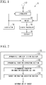
- Fig. 1 is a block diagram showing an example of a configuration of a range measurement device according to the present embodiment.
- a range measurement device 1 includes an oscillator 11, a circulator 12, an antenna 13, a mixer 14, a signal processor 15, and a display 16.
- the range measurement device 1 is, for example, an FMCW radar device, and measures ranges to targets by transmitting radio waves toward the targets and processing an intermediate frequency signal obtained by mixing radio waves which are reflected by the targets and returned to the radar and radio waves which are transmitted.
- the oscillator 11 outputs radio waves that are modulated so that a frequency linearly changes with time to the circulator 12 and the mixer 14.
- the circulator 12 outputs radio waves input from the oscillator 11 to the antenna 13. Also, the circulator 12 outputs radio waves input from the antenna 13 to the mixer 14.
- the antenna 13 radiates radio waves input from the circulator 12 toward the targets, receives the echo radio waves that are scattered by the targets and returned, and outputs the echo radio waves to the circulator 12.
- the antenna 13 can be any antenna such as a dipole antenna, a horn antenna, a parabolic antenna, or an array antenna.
- the mixer 14 outputs an intermediate frequency signal obtained by mixing the radio waves input from the oscillator 11 and the radio waves input from the circulator 12 to the signal processor 15.
- the signal processor 15 performs prescribed signal processing and outputs values of relative amplitudes of the targets and values of ranges to the display 16.
- the display 16 is, for example, a liquid crystal display device, an organic electro-luminescence (EL) display device, or the like, and displays information about the relative strength of the targets and the ranges based on the output from the signal processor 15.
- EL organic electro-luminescence
- Fig. 2 is a block diagram showing an example of a configuration of a signal processor according to the present embodiment.
- the signal processor 15 includes an exponential function fitting section 151, an exponential function extracting section 152, an exponential function information acquiring section 153, and a target information acquiring section 154.
- the exponential function fitting section 151 fits an input intermediate frequency signal with exponential functions whose arguments have real parts and imaginary parts using Prony method.
- the Prony method is a method of fitting a data series with exponential functions.
- the exponential function extracting section 152 extracts exponential functions whose absolute values of the real parts are smaller than or equal to a prescribed value from exponential functions obtained in the fitting process.
- the exponential function information acquiring section 153 acquires values of amplitudes and values of imaginary parts from the extracted exponential functions.
- the target information acquiring section 154 acquires values of relative amplitudes of the targets and values of ranges from acquired exponential function information.
- FMCW radar transmits radio waves that are modulated so that a frequency of the transmitted radio waves linearly changes with time toward the targets.
- t denotes time
- f 0 denotes a carrier frequency
- c denotes the speed of light
- ⁇ f denotes a frequency change width
- T c denotes a time period for changing the frequency.
- the FMCW radar uses an intermediate frequency signal in which a transmitted signal and an echo signal are mixed, its frequency f k (t) is the difference frequency between f T (t) and f Rk ( t ) and is expressed by the following Eq. (3).
- Eq. (5) j denotes an imaginary unit and ⁇ k denotes an amplitude. Also, Eq. (5) is an intermediate frequency signal when there is one target.
- the intermediate frequency signal used in the FMCW radar is a sum of exponential functions.
- a signal that is actually obtained is a data series including numerical values.
- Prony method is known as the method of fitting a data series with exponential functions. Because the intermediate frequency signal used in the FMCW radar is the sum of the exponential functions, if this is fitted to the exponential functions using Prony method, the amplitude ⁇ k and F k , which are parameters of the exponential function, can be obtained.
- the method using Eq. (6) obtains the range R k of the target by digit number directly. Therefore, the method can measure the range accurately.
- Eq. (6) is an equation of an ideal case, the actual intermediate frequency signal contains noise, so that a signal ⁇ IF obtained by fitting using Prony method is expressed by the following Eq. (7).
- ⁇ k is also obtained in addition to the amplitude ⁇ k and F k .
- ⁇ k with respect to the target is 0 in the ideal case.
- ⁇ k with respect to the target is considered to be a small value even if it is not 0.
- ⁇ k with respect to noise is not always a small value, but is considered to be any value. Therefore, depending on a magnitude of ⁇ k , it is possible to efficiently extract the exponential functions for the targets from the obtained exponential functions by removing a part of the exponential functions for noise.
- FIG. 3 is a flowchart of the range measurement processing procedure according to the present embodiment.
- Step S1 The antenna 13 radiates radio waves input from the circulator 12 toward targets.
- Step S2 The antenna 13 receives echo radio waves that are scattered by the targets and returned.
- Step S3 The mixer 14 extracts an intermediate frequency signal obtained by mixing radio waves input from the oscillator 11 and radio waves input from the circulator 12.
- Step S4 The exponential function fitting section 151 fits the extracted intermediate frequency signal with exponential functions whose arguments have real parts and imaginary parts using Prony method.
- Step S5 The exponential function extracting section 152 extracts exponential functions whose absolute values of the real parts in the arguments are smaller than or equal to a prescribed value from exponential functions obtained in the fitting process.
- Step S6 The exponential function information acquiring section 153 acquires values of the amplitudes and values of imaginary parts of the arguments from the extracted exponential functions.
- Step S7 The target information acquiring section 154 acquires values of relative amplitudes of targets and values of ranges from acquired exponential function information.
- the present embodiment is not limited thereto.
- the present embodiment can also be applied to an FMCW LIDAR, which uses a LIDAR (laser radar) instead of a radar, or the like.
- the radar uses radio waves, but the LIDAR uses laser light.
- a medium to be transmitted and received by the range measurement device is not limited to a radio wave, and may be an electromagnetic wave of the LIDAR or the like. Further, a medium to be transmitted and received by the range measurement device may be a sound wave. That is, the "frequency-modulated continuous wave" is radio wave, electromagnetic wave, sound wave, or the like.
- the simulation conditions were that a carrier frequency was 76 [GHz] and radio waves that had been modulated so that the frequency was incremented linearly by 500 [MHz] for 1 [ ⁇ sec] were transmitted from the FMCW radar.
- target information that was obtained when the echo radio waves that were scattered from two targets with the same radar scattering cross-section located at ranges of 11.0 [m] and 11.2 [m] from the radar and returned to the radar were acquired in the environment in which a signal to noise ratio was 20 [dB] was studied.
- Fig. 4 is a diagram showing information of five higher-ranked relative amplitudes within target information obtained in the simulation.
- FIG. 5 is a diagram showing a relationship between the range and the relative strength obtained in the simulation in the present embodiment.
- the horizontal axis represents a range [m] and the vertical axis represents relative strength [dB].
- the accuracy and resolution of the range measurement obtained in the conventional method is 0.3 [m].
- the accuracy and resolution of the range measurement obtained in the conventional method is 0.3 [m].
- the range error obtained for the two targets is 24 [mm] at the maximum, which is less than one-tenth of the range measurement accuracy of the conventional method. From these, according to the present embodiment, the number of targets, the range, and the relative amplitude can be obtained without being limited to the value determined from the frequency change width of the FMCW radar system.
- Fig. 6 is a diagram showing results of a simulation performed by the conventional method.
- the horizontal axis represents a range [m] and the vertical axis represents relative strength [dB].
- the simulation conditions are the same as those of the simulation performed to confirm the effect of the method of the present embodiment.
- the target is located in the vicinity of 11.1 [m] and it is impossible to recognize that there are two targets.
- measurement accuracy and resolution can be improved according to the value determined from a frequency change width of transmitted radio waves.
- all or some processes to be performed by the range measurement device 1 may be performed by recording a program for implementing some or all functions of the range measurement device 1 according to the present invention on a computer-readable storage medium and causing a computer system to read and execute the program recorded on the storage medium.
- the "computer system” used here is assumed to include an operating system (OS) and hardware such as peripheral devices. Also, the "computer system” is assumed to include a homepage providing environment (or a displaying environment) when a World Wide Web (WWW) system is used.
- OS operating system
- WWW World Wide Web
- the "computer-readable storage medium” refers to a storage device such as a flexible disc, a magneto-optical disc, a read-only memory (ROM), a portable medium such as a compact disc-ROM (CD-ROM), and a hard disk embedded in the computer system.
- a "computer-readable recording medium” is assumed to include a medium for retaining a program for a given period of time such as a volatile memory (RAM) inside a computer system that serves as a server or client when a program is transmitted via a network such as the Internet or a communication circuit such as a telephone circuit.
- RAM volatile memory
- the above-described program may be transmitted from a computer system storing the program in a storage device or the like to another computer system via a transmission medium or by transmission waves in a transmission medium.
- the "transmission medium” for transmitting the program refers to a medium which has a function of transmitting information as in a network (a communication network) such as the Internet or a communication circuit (a communication line) such as a telephone circuit.
- the above-described program may be a program for implementing some of the above-described functions.
- the above-described program may be a program capable of implementing the above-described function in combination with a program already recorded on the computer system, i.e., a so-called differential file (differential program).
Landscapes
- Engineering & Computer Science (AREA)
- Radar, Positioning & Navigation (AREA)
- Remote Sensing (AREA)
- Computer Networks & Wireless Communication (AREA)
- Physics & Mathematics (AREA)
- General Physics & Mathematics (AREA)
- Radar Systems Or Details Thereof (AREA)
Abstract
Description
- The present invention relates to a range measurement device, a range measurement method, and a program.
- Priority is claimed on
Japanese Patent Application No. 2020-186766, filed November 9, 2020 - Frequency modulated continuous wave (FMCW) radar transmits radio waves that are modulated so that a frequency changes linearly with time toward targets. Echo radio waves reflected by the targets and returned to the radar are mixed with the transmitted radio waves and converted into an intermediate frequency signal. The intermediate frequency signal is transformed into a spectral signal by a Fourier transform. Because a frequency of the spectral signal and a range to the target are in a proportional relationship, the range to the target can be measured by detecting a frequency at which a spectrum has a peak value. The above is the principle of range measurement in the FMCW radar. At this time, assuming that the frequency change width is Δf, the range resolution Δd is given by (c/(2Δf)}. Here, c denotes the speed of light (see, for example, Non-Patent Literature 1).
- [Non-Patent Literature 1]
"The fundamentals of millimeter wave radar sensors," TEXAS INSTRUMENTS, [online], [retrieved on September 23, 2020], <URL: https://www.ti.com/jp/lit/jajy058> - However, in the prior art, the range to the target is measured in units of range resolution as described in
Non-Patent Literature 1. Thus, in the prior art, there is a problem that range measurement accuracy and resolution are limited to the value determined from a frequency change width of FMCW radar. - The present invention has been made in view of the above-described problem and an objective of the present invention is to provide a range measurement device, a range measurement method, and a program capable of improving measurement accuracy and resolution according to the value determined from a frequency change width of transmitted radio waves.
- According to an aspect of the present invention for accomplishing the above-described objective, there is provided a range measurement device including: a signal processor configured to fit an intermediate frequency signal, obtained by mixing continuous waves which have been frequency-modulated and transmitted toward targets and continuous waves which have been reflected by the targets and returned, with exponential functions whose arguments have real parts and imaginary parts using Prony method.
- Also, in the range measurement device according to the aspect of the present invention, the signal processor may extract exponential functions whose absolute values of the real parts are smaller than or equal to a prescribed value from exponential functions obtained in the fitting process.
- Also, in the range measurement device according to the aspect of the present invention, the signal processor may acquire values of amplitudes and values of the imaginary parts from the extracted exponential functions.
- Also, in the range measurement device according to the aspect of the present invention, the signal processor may acquire values of relative amplitudes of the targets and values of ranges from exponential function information including the values of the amplitudes and the values of the imaginary parts that have been acquired.
- Also, the range measurement device according to the aspect of the present invention may further include a display configured to display target information including the values of the relative amplitudes and the values of the ranges that have been acquired.
- According to an aspect of the present invention for accomplishing the above-described objective, there is provided a range measurement method including fitting, by a computer, an intermediate frequency signal, obtained by mixing continuous waves which have been frequency-modulated and transmitted toward targets and continuous waves which have been reflected by the targets and returned, with exponential functions whose arguments have real parts and imaginary parts using Prony method.
- According to an aspect of the present invention for accomplishing the above-described objective, there is provided a program for causing a computer to fit an intermediate frequency signal, obtained by mixing continuous waves which have been frequency-modulated and transmitted toward targets and continuous waves which have been reflected by the targets and returned, with exponential functions whose arguments have real parts and imaginary parts using Prony method.
- According to the present invention, measurement accuracy and resolution can be improved according to the value determined from a frequency change width of transmitted radio waves.
-
-
Fig. 1 is a block diagram showing an example of a configuration of a range measurement device according to an embodiment. -
Fig. 2 is a block diagram showing an example of a configuration of a signal processor according to an embodiment. -
Fig. 3 is a flowchart of a range measurement processing procedure according to an embodiment. -
Fig. 4 is a diagram showing information of five higher-ranked relative amplitudes within target information obtained by a simulation. -
Fig. 5 is a diagram showing a relationship between a range and relative strength obtained by a simulation according to the present embodiment. -
Fig. 6 is a diagram showing results of a simulation performed in a conventional method. - Hereinafter, embodiments of the present invention will be described with reference to the drawings. Also, in the following example, an example in which a range measurement device is applied to a radar device will be described.
-
Fig. 1 is a block diagram showing an example of a configuration of a range measurement device according to the present embodiment. As shown inFig. 1 , arange measurement device 1 includes anoscillator 11, acirculator 12, anantenna 13, amixer 14, asignal processor 15, and adisplay 16. - The
range measurement device 1 is, for example, an FMCW radar device, and measures ranges to targets by transmitting radio waves toward the targets and processing an intermediate frequency signal obtained by mixing radio waves which are reflected by the targets and returned to the radar and radio waves which are transmitted. - The
oscillator 11 outputs radio waves that are modulated so that a frequency linearly changes with time to thecirculator 12 and themixer 14. - The
circulator 12 outputs radio waves input from theoscillator 11 to theantenna 13. Also, thecirculator 12 outputs radio waves input from theantenna 13 to themixer 14. - The
antenna 13 radiates radio waves input from thecirculator 12 toward the targets, receives the echo radio waves that are scattered by the targets and returned, and outputs the echo radio waves to thecirculator 12. Theantenna 13 can be any antenna such as a dipole antenna, a horn antenna, a parabolic antenna, or an array antenna. - The
mixer 14 outputs an intermediate frequency signal obtained by mixing the radio waves input from theoscillator 11 and the radio waves input from thecirculator 12 to thesignal processor 15. - The
signal processor 15 performs prescribed signal processing and outputs values of relative amplitudes of the targets and values of ranges to thedisplay 16. - The
display 16 is, for example, a liquid crystal display device, an organic electro-luminescence (EL) display device, or the like, and displays information about the relative strength of the targets and the ranges based on the output from thesignal processor 15. - Next, an example of a configuration of the
signal processor 15 will be described.Fig. 2 is a block diagram showing an example of a configuration of a signal processor according to the present embodiment. As shown inFig. 2 , thesignal processor 15 includes an exponentialfunction fitting section 151, an exponentialfunction extracting section 152, an exponential functioninformation acquiring section 153, and a targetinformation acquiring section 154. - The exponential
function fitting section 151 fits an input intermediate frequency signal with exponential functions whose arguments have real parts and imaginary parts using Prony method. The Prony method is a method of fitting a data series with exponential functions. - The exponential
function extracting section 152 extracts exponential functions whose absolute values of the real parts are smaller than or equal to a prescribed value from exponential functions obtained in the fitting process. - The exponential function
information acquiring section 153 acquires values of amplitudes and values of imaginary parts from the extracted exponential functions. - The target
information acquiring section 154 acquires values of relative amplitudes of the targets and values of ranges from acquired exponential function information. - Next, an example of a range measurement method will be described.
- FMCW radar transmits radio waves that are modulated so that a frequency of the transmitted radio waves linearly changes with time toward the targets. A frequency fT(t) of the transmitted radio waves is expressed by the following Eq. (1).
[Math. 1]
- In Eq. (1), t denotes time, f0 denotes a carrier frequency, c denotes the speed of light, Δf denotes a frequency change width, and Tc denotes a time period for changing the frequency.
- Because an echo signal of the target located at a range Rk from the radar reaches the radar after a time period of (2Rk)/c, its frequency fR
k (t) is expressed by the following Eq. (2).
[Math. 2]
- Because the FMCW radar uses an intermediate frequency signal in which a transmitted signal and an echo signal are mixed, its frequency fk(t) is the difference frequency between fT(t) and fRk (t) and is expressed by the following Eq. (3).
[Math. 3]
- As shown in Eq. (3), fk(t) denotes a constant value regardless of time t. Assuming that this value is Fk, the range Rk can be obtained using the following Eq. (4).
[Math. 4]
- Also, the intermediate frequency signal SIF(t) is expressed by the following Eq. (5) when Fk is used.
[Math. 5]
- In Eq. (5), j denotes an imaginary unit and Ȧk denotes an amplitude. Also, Eq. (5) is an intermediate frequency signal when there is one target.
- Generalizing this, an intermediate frequency signal for p targets is given by the following Eq. (6).
[Math. 6]
- From Eq. (6), it can be seen that the intermediate frequency signal used in the FMCW radar is a sum of exponential functions. A signal that is actually obtained is a data series including numerical values. For example, Prony method is known as the method of fitting a data series with exponential functions. Because the intermediate frequency signal used in the FMCW radar is the sum of the exponential functions, if this is fitted to the exponential functions using Prony method, the amplitude Ȧk and Fk, which are parameters of the exponential function, can be obtained.
- Different from the conventional method which measures ranges in units of the range resolution determined by the frequency change width, the method using Eq. (6) obtains the range Rk of the target by digit number directly. Therefore, the method can measure the range accurately.
- However, Eq. (6) is an equation of an ideal case, the actual intermediate frequency signal contains noise, so that a signal ŜIF obtained by fitting using Prony method is expressed by the following Eq. (7).
[Math. 7]
- When the actual intermediate frequency signal is fitted using Prony method, αk is also obtained in addition to the amplitude Ȧk and Fk. As shown in Eq. (6), αk with respect to the target is 0 in the ideal case. Thus, when a signal containing noise is fitted using Prony method, αk with respect to the target is considered to be a small value even if it is not 0. On the other hand, αk with respect to noise is not always a small value, but is considered to be any value. Therefore, depending on a magnitude of αk, it is possible to efficiently extract the exponential functions for the targets from the obtained exponential functions by removing a part of the exponential functions for noise.
- Next, an example of a range measurement processing procedure will be described.
Fig. 3 is a flowchart of the range measurement processing procedure according to the present embodiment. - (Step S1) The
antenna 13 radiates radio waves input from thecirculator 12 toward targets. - (Step S2) The
antenna 13 receives echo radio waves that are scattered by the targets and returned. - (Step S3) The
mixer 14 extracts an intermediate frequency signal obtained by mixing radio waves input from theoscillator 11 and radio waves input from thecirculator 12. - (Step S4) The exponential function
fitting section 151 fits the extracted intermediate frequency signal with exponential functions whose arguments have real parts and imaginary parts using Prony method. - (Step S5) The exponential
function extracting section 152 extracts exponential functions whose absolute values of the real parts in the arguments are smaller than or equal to a prescribed value from exponential functions obtained in the fitting process. - (Step S6) The exponential function
information acquiring section 153 acquires values of the amplitudes and values of imaginary parts of the arguments from the extracted exponential functions. - (Step S7) The target
information acquiring section 154 acquires values of relative amplitudes of targets and values of ranges from acquired exponential function information. - Although the FMCW radar has been described in the above example, the present embodiment is not limited thereto. For example, the present embodiment can also be applied to an FMCW LIDAR, which uses a LIDAR (laser radar) instead of a radar, or the like. The radar uses radio waves, but the LIDAR uses laser light. As described above, a medium to be transmitted and received by the range measurement device is not limited to a radio wave, and may be an electromagnetic wave of the LIDAR or the like.
Further, a medium to be transmitted and received by the range measurement device may be a sound wave. That is, the "frequency-modulated continuous wave" is radio wave, electromagnetic wave, sound wave, or the like. - Next, an example of results of a simulation performed to confirm the effect of the method of the present embodiment will be described.
- The simulation conditions were that a carrier frequency was 76 [GHz] and radio waves that had been modulated so that the frequency was incremented linearly by 500 [MHz] for 1 [µsec] were transmitted from the FMCW radar. In the simulation, target information that was obtained when the echo radio waves that were scattered from two targets with the same radar scattering cross-section located at ranges of 11.0 [m] and 11.2 [m] from the radar and returned to the radar were acquired in the environment in which a signal to noise ratio was 20 [dB] was studied.
- A result of extracting exponential functions whose absolute values of real parts in the arguments are smaller than or equal to 0.001 from exponential functions obtained by fitting an intermediate frequency signal with exponential functions whose arguments have real parts and imaginary parts using Prony method, acquiring relative amplitudes of targets from the amplitude values of the exponential functions, and acquiring ranges to the targets from the imaginary parts in the arguments of the exponential functions is shown in
Fig. 4. Fig. 4 is a diagram showing information of five higher-ranked relative amplitudes within target information obtained in the simulation. - A result of illustrating target information up to the range of 20 [m] among the target information obtained in the simulation is shown in
Fig. 5. Fig. 5 is a diagram showing a relationship between the range and the relative strength obtained in the simulation in the present embodiment. InFig. 5 , the horizontal axis represents a range [m] and the vertical axis represents relative strength [dB]. - From
Fig. 4 , it can be seen that relative amplitudes ofrankings rankings rankings rankings - Because the frequency change width used in the simulation is 500 [MHz], the accuracy and resolution of the range measurement obtained in the conventional method is 0.3 [m]. On the other hand, according to the present embodiment, it is possible to identify two targets close to a range of 0.3 [m] or less as shown in
Figs. 4 and5 . Also, the range error obtained for the two targets is 24 [mm] at the maximum, which is less than one-tenth of the range measurement accuracy of the conventional method. From these, according to the present embodiment, the number of targets, the range, and the relative amplitude can be obtained without being limited to the value determined from the frequency change width of the FMCW radar system. - Here, a comparative example will be described.
Fig. 6 is a diagram showing results of a simulation performed by the conventional method. InFig. 6 , the horizontal axis represents a range [m] and the vertical axis represents relative strength [dB]. The simulation conditions are the same as those of the simulation performed to confirm the effect of the method of the present embodiment. As shown inFig. 6 , in the conventional method, it is only known that the target is located in the vicinity of 11.1 [m] and it is impossible to recognize that there are two targets. - As described above, in the present embodiment, fitting a frequency included in intermediate frequency radio waves, obtained by mixing echo radio waves and transmitted radio waves, with exponential functions whose arguments have real parts and imaginary parts using Prony method is performed and the exponential functions whose absolute values of the real parts in the arguments are smaller than or equal to a prescribed value are extracted. In the present embodiment, values of the amplitudes and values of the imaginary parts in the arguments are acquired from the extracted exponential functions and values of relative amplitudes of the targets and values of ranges are acquired from exponential function information acquired.
- Thereby, according to the present embodiment, measurement accuracy and resolution can be improved according to the value determined from a frequency change width of transmitted radio waves.
- Also, all or some processes to be performed by the
range measurement device 1 may be performed by recording a program for implementing some or all functions of therange measurement device 1 according to the present invention on a computer-readable storage medium and causing a computer system to read and execute the program recorded on the storage medium. The "computer system" used here is assumed to include an operating system (OS) and hardware such as peripheral devices. Also, the "computer system" is assumed to include a homepage providing environment (or a displaying environment) when a World Wide Web (WWW) system is used. Also, the "computer-readable storage medium" refers to a storage device such as a flexible disc, a magneto-optical disc, a read-only memory (ROM), a portable medium such as a compact disc-ROM (CD-ROM), and a hard disk embedded in the computer system. Furthermore, a "computer-readable recording medium" is assumed to include a medium for retaining a program for a given period of time such as a volatile memory (RAM) inside a computer system that serves as a server or client when a program is transmitted via a network such as the Internet or a communication circuit such as a telephone circuit. - Also, the above-described program may be transmitted from a computer system storing the program in a storage device or the like to another computer system via a transmission medium or by transmission waves in a transmission medium. Here, the "transmission medium" for transmitting the program refers to a medium which has a function of transmitting information as in a network (a communication network) such as the Internet or a communication circuit (a communication line) such as a telephone circuit. Also, the above-described program may be a program for implementing some of the above-described functions. Further, the above-described program may be a program capable of implementing the above-described function in combination with a program already recorded on the computer system, i.e., a so-called differential file (differential program).
- While modes for carrying out the present invention have been described using embodiments, the present invention is not limited to such embodiments in any way and various modifications and replacements can be added without departing from the scope of the present invention.
-
- 1 Range measurement device
- 11 Oscillator
- 12 Circulator
- 13 Antenna
- 14 Mixer
- 15 Signal processor
- 16 Display
- 151 Exponential function fitting section
- 152 Exponential function extracting section
- 153 Exponential function information acquiring section
- 154 Target information acquiring section
Claims (7)
- A range measurement device comprising:
a signal processor configured to fit an intermediate frequency signal, obtained by mixing continuous waves which have been frequency-modulated and transmitted toward targets and continuous waves which have been reflected by the targets and returned, with exponential functions whose arguments have real parts and imaginary parts using Prony method. - The range measurement device according to claim 1, wherein the signal processor extracts exponential functions whose absolute values of the real parts are smaller than or equal to a prescribed value from exponential functions obtained in the fitting process.
- The range measurement device according to claim 2, wherein the signal processor acquires values of amplitudes and values of the imaginary parts from the extracted exponential functions.
- The range measurement device according to claim 3, wherein the signal processor acquires values of relative amplitudes of the targets and values of ranges from exponential function information including the values of the amplitudes and the values of the imaginary parts that have been acquired.
- The range measurement device according to claim 4, further comprising a display configured to display target information including the values of the relative amplitudes and the values of the ranges that have been acquired.
- A range measurement method comprising:
fitting, by a computer, an intermediate frequency signal, obtained by mixing continuous waves which have been frequency-modulated and transmitted toward targets and continuous waves which have been reflected by the targets and returned, with exponential functions whose arguments have real parts and imaginary parts using Prony method. - A program for causing a computer to:
fit an intermediate frequency signal, obtained by mixing continuous waves which have been frequency-modulated and transmitted toward targets and continuous waves which have been reflected by the targets and returned, with exponential functions whose arguments have real parts and imaginary parts using Prony method.
Applications Claiming Priority (2)
| Application Number | Priority Date | Filing Date | Title |
|---|---|---|---|
| JP2020186766A JP7161230B2 (en) | 2020-11-09 | 2020-11-09 | DISTANCE MEASURING DEVICE, DISTANCE MEASURING METHOD, AND PROGRAM |
| PCT/JP2021/041046 WO2022097748A1 (en) | 2020-11-09 | 2021-11-08 | Distance measuring device, distance measuring method, and program |
Publications (2)
| Publication Number | Publication Date |
|---|---|
| EP4116737A1 true EP4116737A1 (en) | 2023-01-11 |
| EP4116737A4 EP4116737A4 (en) | 2024-05-01 |
Family
ID=81458375
Family Applications (1)
| Application Number | Title | Priority Date | Filing Date |
|---|---|---|---|
| EP21889299.0A Pending EP4116737A4 (en) | 2020-11-09 | 2021-11-08 | DISTANCE MEASURING DEVICE, DISTANCE MEASURING METHOD AND PROGRAM |
Country Status (4)
| Country | Link |
|---|---|
| US (1) | US20230168340A1 (en) |
| EP (1) | EP4116737A4 (en) |
| JP (1) | JP7161230B2 (en) |
| WO (1) | WO2022097748A1 (en) |
Family Cites Families (16)
| Publication number | Priority date | Publication date | Assignee | Title |
|---|---|---|---|---|
| JPH0436679A (en) * | 1990-05-31 | 1992-02-06 | Aloka Co Ltd | Azimuth angle measuring instrument by beam scanning |
| JP2560222B2 (en) * | 1990-07-13 | 1996-12-04 | 郵政省通信総合研究所長 | Pulsed chirp radar transmission modulation signal forming method and pulsed chirp radar device |
| AU7908698A (en) * | 1997-07-02 | 1999-01-25 | Ekko Dane Production A/S | Radar plant and measurement technique for determination of the orientation and the depth of buried objects |
| WO1999010757A1 (en) * | 1997-08-22 | 1999-03-04 | Siemens Aktiengesellschaft | Method and device for measuring distance and speed |
| KR100572670B1 (en) * | 2004-08-31 | 2006-04-24 | 심관식 | Parameter Estimation Method of Time Series Data by Fourier Transform |
| DE102007008944A1 (en) * | 2006-02-24 | 2007-09-13 | Adc Automotive Distance Control Systems Gmbh | Radar system for detecting e.g. length of truck in traffic condition, has reception unit for receiving power reflected by objects such as motor vehicle, and signal processing units for processing received power |
| CN104515990B (en) * | 2014-12-18 | 2017-02-22 | 河海大学 | Automotive anti-collision radar multi-object identification method based on PRONY spectral line estimation |
| WO2018174172A1 (en) * | 2017-03-24 | 2018-09-27 | 国立研究開発法人宇宙航空研究開発機構 | Observation device, observation method, and program |
| JP2019101004A (en) * | 2017-11-28 | 2019-06-24 | 正宣 神力 | Information acquisition device based on echo signal, rader device and pulse compression device |
| US10830881B2 (en) * | 2018-03-20 | 2020-11-10 | Panosense Inc. | Active signal detection using adaptive identification of a noise floor |
| JP2019168255A (en) * | 2018-03-22 | 2019-10-03 | 株式会社東芝 | Pulse compression radar apparatus and radar signal processing method thereof |
| US20190295319A1 (en) * | 2018-03-23 | 2019-09-26 | Bodidata, Inc. | Systems and methods for generating a refined 3d model using radar and optical camera data |
| US10969465B2 (en) * | 2018-05-01 | 2021-04-06 | Mitsubishi Electric Research Laboratories, Inc. | Reference-free nonlinearity correction for FMCW-based sensing systems |
| US10890656B2 (en) * | 2018-08-01 | 2021-01-12 | Raytheon Company | Weapons detection system using ultra-wide band radar |
| US10859691B2 (en) * | 2018-08-22 | 2020-12-08 | Infineon Technologies Ag | Radar range accuracy improvement method |
| JP2020186766A (en) | 2019-05-14 | 2020-11-19 | スズキ株式会社 | Vehicle driving device |
-
2020
- 2020-11-09 JP JP2020186766A patent/JP7161230B2/en active Active
-
2021
- 2021-11-08 EP EP21889299.0A patent/EP4116737A4/en active Pending
- 2021-11-08 US US17/918,274 patent/US20230168340A1/en active Pending
- 2021-11-08 WO PCT/JP2021/041046 patent/WO2022097748A1/en not_active Ceased
Also Published As
| Publication number | Publication date |
|---|---|
| JP2022076377A (en) | 2022-05-19 |
| WO2022097748A1 (en) | 2022-05-12 |
| EP4116737A4 (en) | 2024-05-01 |
| US20230168340A1 (en) | 2023-06-01 |
| JP7161230B2 (en) | 2022-10-26 |
Similar Documents
| Publication | Publication Date | Title |
|---|---|---|
| US10746865B2 (en) | Radar system | |
| US11067682B2 (en) | Radar apparatus | |
| EP1262793A1 (en) | Method and apparatus for removing a DC-offset in the frequency spectrum before performing Fourier transform in a radar | |
| CN105607051B (en) | Method for measuring distance between FMCW range units and target | |
| EP0425006B1 (en) | FM-CW radar apparatus | |
| US20230400580A1 (en) | Method of performing detection using frequency modulated continuous wave and lidar | |
| US20100305885A1 (en) | System and method for detecting adulteration of fuel or other material using wireless measurements | |
| US20240377241A1 (en) | Vibrometry and sound reproduction of acoustic sources on moving platforms using radar | |
| JP6164918B2 (en) | Radar equipment | |
| Ciattaglia et al. | Performance evaluation of vibrational measurements through mmWave radars | |
| US20230168340A1 (en) | Range measurement device, range measurement method, and storage medium | |
| EP4116736A1 (en) | Distance measuring device, distance measuring method, and program | |
| JP3198949B2 (en) | Radar signal processing method and radar apparatus using the method | |
| KR102259887B1 (en) | Post processing Technique to improve range resolution in FMCW LiDAR System | |
| JP6177008B2 (en) | Radar equipment | |
| RU2658558C1 (en) | Method for measuring a distance to a controlled environment with a waveguide lfm radar | |
| CN112083405B (en) | A target detection method and related devices based on mixed waveforms | |
| RU2796220C1 (en) | Method for radar monopulse measurement of range and radial velocity of targets when sounding with a signal with linear frequency modulation | |
| CN114459567B (en) | Distance measurement method, device, medicine box, operating equipment, electronic equipment and medium | |
| EP4711807A1 (en) | Thickness measurement system | |
| US12422298B2 (en) | Radar level gauge system and method with improved filling level determination | |
| Meister et al. | Using FMCW Radar and Range-Gated Clutter Suppression for Trombone Slide Position Detection | |
| KR20250119451A (en) | Measurement system | |
| US12117516B2 (en) | Radar apparatus and distance measurement method | |
| Ma et al. | Bistatic high frequency radar ocean surface cross section for an FMCW source with an antenna on a floating platform |
Legal Events
| Date | Code | Title | Description |
|---|---|---|---|
| STAA | Information on the status of an ep patent application or granted ep patent |
Free format text: STATUS: THE INTERNATIONAL PUBLICATION HAS BEEN MADE |
|
| PUAI | Public reference made under article 153(3) epc to a published international application that has entered the european phase |
Free format text: ORIGINAL CODE: 0009012 |
|
| STAA | Information on the status of an ep patent application or granted ep patent |
Free format text: STATUS: REQUEST FOR EXAMINATION WAS MADE |
|
| 17P | Request for examination filed |
Effective date: 20221005 |
|
| AK | Designated contracting states |
Kind code of ref document: A1 Designated state(s): AL AT BE BG CH CY CZ DE DK EE ES FI FR GB GR HR HU IE IS IT LI LT LU LV MC MK MT NL NO PL PT RO RS SE SI SK SM TR |
|
| DAV | Request for validation of the european patent (deleted) | ||
| DAX | Request for extension of the european patent (deleted) | ||
| A4 | Supplementary search report drawn up and despatched |
Effective date: 20240402 |
|
| RIC1 | Information provided on ipc code assigned before grant |
Ipc: G01S 13/02 20060101ALN20240325BHEP Ipc: G01S 7/35 20060101ALI20240325BHEP Ipc: G01S 13/34 20060101AFI20240325BHEP |