EP4116726A1 - Interchangeable sample cell for dnp-nmr measurements - Google Patents
Interchangeable sample cell for dnp-nmr measurements Download PDFInfo
- Publication number
- EP4116726A1 EP4116726A1 EP21184072.3A EP21184072A EP4116726A1 EP 4116726 A1 EP4116726 A1 EP 4116726A1 EP 21184072 A EP21184072 A EP 21184072A EP 4116726 A1 EP4116726 A1 EP 4116726A1
- Authority
- EP
- European Patent Office
- Prior art keywords
- sample
- nmr
- cavity
- sample cell
- sample cavity
- Prior art date
- Legal status (The legal status is an assumption and is not a legal conclusion. Google has not performed a legal analysis and makes no representation as to the accuracy of the status listed.)
- Granted
Links
Images




Classifications
-
- G—PHYSICS
- G01—MEASURING; TESTING
- G01R—MEASURING ELECTRIC VARIABLES; MEASURING MAGNETIC VARIABLES
- G01R33/00—Arrangements or instruments for measuring magnetic variables
- G01R33/20—Arrangements or instruments for measuring magnetic variables involving magnetic resonance
- G01R33/28—Details of apparatus provided for in groups G01R33/44 - G01R33/64
- G01R33/30—Sample handling arrangements, e.g. sample cells, spinning mechanisms
-
- G—PHYSICS
- G01—MEASURING; TESTING
- G01N—INVESTIGATING OR ANALYSING MATERIALS BY DETERMINING THEIR CHEMICAL OR PHYSICAL PROPERTIES
- G01N24/00—Investigating or analyzing materials by the use of nuclear magnetic resonance, electron paramagnetic resonance or other spin effects
- G01N24/08—Investigating or analyzing materials by the use of nuclear magnetic resonance, electron paramagnetic resonance or other spin effects by using nuclear magnetic resonance
-
- G—PHYSICS
- G01—MEASURING; TESTING
- G01N—INVESTIGATING OR ANALYSING MATERIALS BY DETERMINING THEIR CHEMICAL OR PHYSICAL PROPERTIES
- G01N24/00—Investigating or analyzing materials by the use of nuclear magnetic resonance, electron paramagnetic resonance or other spin effects
- G01N24/10—Investigating or analyzing materials by the use of nuclear magnetic resonance, electron paramagnetic resonance or other spin effects by using electron paramagnetic resonance
-
- G—PHYSICS
- G01—MEASURING; TESTING
- G01R—MEASURING ELECTRIC VARIABLES; MEASURING MAGNETIC VARIABLES
- G01R33/00—Arrangements or instruments for measuring magnetic variables
- G01R33/20—Arrangements or instruments for measuring magnetic variables involving magnetic resonance
- G01R33/28—Details of apparatus provided for in groups G01R33/44 - G01R33/64
- G01R33/32—Excitation or detection systems, e.g. using radio frequency signals
- G01R33/34—Constructional details, e.g. resonators, specially adapted to MR
- G01R33/34092—RF coils specially adapted for NMR spectrometers
-
- G—PHYSICS
- G01—MEASURING; TESTING
- G01R—MEASURING ELECTRIC VARIABLES; MEASURING MAGNETIC VARIABLES
- G01R33/00—Arrangements or instruments for measuring magnetic variables
- G01R33/20—Arrangements or instruments for measuring magnetic variables involving magnetic resonance
- G01R33/28—Details of apparatus provided for in groups G01R33/44 - G01R33/64
- G01R33/30—Sample handling arrangements, e.g. sample cells, spinning mechanisms
- G01R33/31—Temperature control thereof
-
- G—PHYSICS
- G01—MEASURING; TESTING
- G01R—MEASURING ELECTRIC VARIABLES; MEASURING MAGNETIC VARIABLES
- G01R33/00—Arrangements or instruments for measuring magnetic variables
- G01R33/20—Arrangements or instruments for measuring magnetic variables involving magnetic resonance
- G01R33/62—Arrangements or instruments for measuring magnetic variables involving magnetic resonance using double resonance
Definitions
- the invention relates to a sample cell for performing DNP-NMR measurements, for interchangeable use in an EPR microwave resonator.
- Nuclear magnetic resonance (NMR) spectroscopy is a widely used and very important method in material science, chemistry and biology.
- scientists use NMR spectroscopy to determine the structure and/or the dynamics of an examined sample or compound.
- one major problem of NMR spectroscopy is that NMR spectroscopy generally suffers from low sensitivity.
- the low sensitivity and the accompanying small signal intensities can for example be overcome by signal averaging to obtain a sufficiently high signal-to-noise ratio.
- signal averaging can be a time-consuming and cost-intensive process.
- DNP Dynamic nuclear polarization
- the spin polarization from paramagnetic electrons is transferred to nuclei of the sample to be measured.
- the nuclear spins are aligned proportional to the extent that the electron spins are aligned, wherein the electron spin polarization is enhanced using microwave radiation. Accordingly, more nuclear spins in the sample become aligned as compared to the level that would result from the Boltzmann distribution in thermal equilibrium, so hyperpolarization of the sample is achieved. Due to the larger number of aligned nuclear spins the NMR signals are enhanced.
- DNP-NMR measurements are mainly carried out on solid-state samples, but it is also possible to carry out DNP-NMR measurements on liquid samples.
- a DNP-NMR measurement of a liquid sample the liquid sample is typically filled in a sample tube.
- the sample to be measured is placed in an electron paramagnetic resonance (EPR) resonator.
- the sample is then irradiated with a microwave (MW) magnetic field (near or at the EPR) B 1 of appropriate direction and amplitude, wherein the sample is in an appropriate static background magnetic field B 0 , to saturate the electron spin transition.
- MW microwave
- B 1 microwave
- B 1 microwave
- B 1 microwave
- B 1 microwave
- B 1 microwave
- B 1 microwave
- B 1 microwave
- B 1 microwave
- B 1 microwave
- B 1 microwave
- B 1 microwave
- B 1 microwave
- B 1 microwave
- B 1 microwave
- B 1 microwave
- B 1 microwave
- B 1 microwave
- B 1 microwave
- B 1 magnetic
- the dual resonance structure comprises a MW resonator for generating electromagnetic fields suitable for EPR and an RF resonator, namely a strip resonator, for generating electromagnetic fields suitable for NMR.
- a strip resonator for generating electromagnetic fields suitable for NMR.
- One part of the strip resonator also forms a part of the MW resonator.
- a ring is placed directly onto the strip resonator. The ring is used to hold a liquid sample to be measured.
- the ring has to be cleaned after each measurement to ensure that no residues of former measurements disturb the new measurements. Furthermore, depending on the solvent used for the measurement it may also happen that the solvent evaporates before the measurement has finished. Further, the filling factor of the RF resonator is small.
- US 2016/0334476 A1 depicts a tuneable static DNP probe comprising a coilform with a sample cavity.
- a NMR coil for performing NMR measurements is wrapped around the coilform.
- sample cell for performing DNP-NMR measurements, for interchangeable use in an EPR microwave resonator, with the sample cell comprising
- the present invention proposes a sample cell with a flat sample cavity and an NMR coil wound around the flat sample cavity, which is directly arranged at the sample cell, which is designed to be exchanged (together with the sample) at an EPR microwave resonator.
- the sample cell is designed in such a way that the q factor of the EPR microwave resonator is affected as little as possible, i.e. may remain high with the sample cell inserted.
- the q factor (also called quality factor) is a dimensionless parameter that describes the dampening of a resonator; the lower the dampening, the higher is the q factor.
- the measurement quality for DNP-NMR measurements can be improved when the q factor is large.
- the sample cell is dimensioned such that, when the sample cell is positioned inside an EPR microwave resonator during a DNP-NMR measurement, the liquid sample filled into the sample cell may be located practically completely in a region of low MW electric field; this is achieved by a flat sample cavity, which can be arranged in a basically plane shaped maximum of the MW magnetic field, which corresponds to a basically plane shaped minimum of the MW electric field. In this way the MW magnetic field irradiates the liquid sample and saturates the electron spin transition while the absorption of MW electrical energy by the liquid sample is minimized.
- the quality of the DNP-NMR measurements can be improved, the dielectric losses as well as the heating of the liquid sample can be minimized and the measurements can be performed at stable temperatures. Also sample decomposition due to increased temperatures of the liquid sample can be prevented and the reproducibility of the measurements can be improved.
- the NMR coil can be located very close to the flat sample cavity and in this way the sample, and the inner region of the NMR coil can be filled to a large extent with the liquid sample. This results in a high NMR signal intensity.
- the sample cell can be easily exchanged at an ESR resonator and is inexpensive to produce, so that it can be used as a consumable, if desired. Thereby, cross-contaminations between samples do not occur.
- the sample cell is suitable for mass production and widespread use throughout different laboratories, what helps to increase comparability of measurement results.
- the flat sample cavity has typically a circular or an ellipsoidal or a rectangular cross-section (in the sample cavity plane) and a very small thickness (perpendicular to the sample cavity plane).
- the q factor depends, among other things, on the thickness of the flat sample cavity.
- a flat sample cavity with a small thickness can be aligned easier with the maximum of the MW magnetic field and the minimum of the MW electric field inside an EPR microwave resonator. By choosing a small thickness of the flat sample cavity the q factor reaches a larger value and heating of the liquid sample can be minimized.
- the cross-section of the flat sample cavity in the sample cavity plane is shaped substantially quadratically or substantially rectangularly, and the flat sample cavity is formed substantially cuboidally.
- a flat sample cavity formed in such a manner comparably large sample volumes can be arranged in a homogenous region of the B 1 field of an EPR resonator, and in a region of low MV electric field strength of the EPR resonator.
- a typical maximum height H of the flat sample cavity is H ⁇ 0.5mm or even H ⁇ 0.3mm. Also typically, H ⁇ 1/20*L and H ⁇ 1/20*W.
- the transverse dimensions i.e. the maximum length L and the maximum width W, are typically given by the available space inside the EPR microwave resonator (also called EPR cavity).
- the longitudinal dimension (thickness, maximum height H) is determined (limited) by the EPR wavelength (microwave wavelength) ⁇ , typically with H ⁇ ⁇ /10.
- the sample cell is oriented with its sample cavity plane (also called transverse plane, in which L and W extend) along a plane of minimum electric field of the applied microwave mode. In this way the heating of the liquid sample caused by the MW electrical energy can be minimized.
- the sample cavity plane is centrally arranged inside the flat sample cavity with respect to the direction perpendicular to the sample cavity plane.
- the sample cell preferably is basically plate shaped, wherein the sample cell extends with a maximum length LS and a maximum width WS in the sample cavity plane, wherein LS ⁇ WS, preferably LS ⁇ 4*WS, wherein the sample cell extends with a maximum height HS perpendicular to the sample cavity plane, wherein HS ⁇ LS and HS ⁇ WS, in particular HS ⁇ 1/10*LS and HS ⁇ 1/10*WS, and wherein for the height HS of the sample cell, the following applies: HS ⁇ 2.5 mm, preferably HS ⁇ 1.5 mm, most preferably HS ⁇ 1.0 mm.
- Such sample cells can be easily manufactured and the dimensions can be suitable to provide enough stability to the sample cell with the flat sample cavity. Further, such sample cells are easy to handle and can simply be inserted into an EPR microwave resonator.
- the sample cell comprises two channels for filling the liquid sample into the flat sample cavity or to remove the liquid sample from the flat sample cavity, in particular wherein the channels are positioned next to each other.
- the liquid sample can be easily filled into or removed from the sample cell.
- only a fraction of the flat sample cavity is exposed to the environment which can reduce the entry of impurities and lower the evaporation of the solvent of the liquid sample.
- the (internal) NMR coil wound around the flat sample cavity generates an additional RF magnetic field B 2 .
- the NMR coil allows simultaneous excitation and measurement of the nuclear spins of the sample to be measured.
- the shape and the orientation of the NMR coil are chosen such that the interference with the MW field is minimized. Furthermore, the best q factors are received when the plane of the NMR coil and the sample cavity plane are as close together as possible.
- the NMR coil comprises two conductor loops.
- the two loops are wound in a pancake type fashion.
- the NMR coil may comprise even more than two conductor loops.
- a preferred embodiment of the inventive sample cell is characterized in that the sample cell comprises a first plate and a second plate, that the flat sample cavity is formed by a cavity recess in the first plate and/or a cavity recess in the second plate, and that the first plate and second plate are joined to each other, with the flat sample cavity enclosed between them.
- the cavity recess and thereby the geometry of the flat sample cavity can be freely designed (in particular depending on the planned measurement experiment).
- the cavity recess can for example be etched by laser-assisted micromachining. Fused silica or borosilicate can be used as a material for the plates (both are suitable for laser-assisted micromachining).
- a coil recess is formed in the first plate and/or a coil recess is formed in the second plate, wherein the NMR coil is arranged in the coil recess of the first plate and/or the coil recess of the second plate, in particular wherein the NMR coil is enclosed between the fist plate and the second plate.
- the NMR coil When joining the first plate and the second plate with the NMR coil arranged ("sandwiched") between them the NMR coil is protected inside the two plates and the risk of damaging the NMR coil can be minimized, e.g. if the sample cell is inserted into a holder. Furthermore, the flat sample cavity and the NMR coil can be brought into close proximity which improves the quality of DNP-NMR measurements.
- the coil recess can for example be etched by laser-assisted micromachining.
- the flat sample cavity is formed only by a cavity recess of the first plate, and only the second plate forms a coil recess, in which the NMR coil is arranged.
- the cavity recess only has to be etched into the first plate and the coil recess only has to be etched into the second plate. The two plates can then be joined in an uncomplicated way.
- the NMR coil and the flat sample cavity are in close proximity with respect to the direction perpendicular to the sample cavity plane.
- the offset distance O d affects the q factor.
- the q factor generally reaches its highest value when the offset distance O d is minimal. Accordingly, with a small O d , a large q factor is achieved, thereby achieving a better quality of the NMR measurements.
- the scope of the present invention also includes an NMR probe for performing DNP-NMR measurements, for use in an EPR microwave resonator, with the NMR probe comprising
- the NMR probe forms at least one tempering channel for varying and/or keeping a temperature of the liquid sample to be measured, in particular wherein at least in a region of the flat sample cavity, the at least one tempering channel extends parallel to the flat sample cavity and adjacent to the sample cell.
- a tempering fluid flow typically a gas flow
- the tempering channel preferably extends on the side of the sample cell closest to the flat sample cavity.
- a temperature control system may be used for controlling the temperature of the sample via the tempering fluid flow.
- the NMR probe comprises a dielectric sleeve, wherein the dielectric sleeve at least partially limits the at least one tempering channel, in particular wherein an inner region of the dielectric sleeve is subdivided into two tempering channels with the sample cell inserted in the sample cell holder.
- the dielectric sleeve With the dielectric sleeve, a tempering channel or channels can be formed particularly easily.
- the dielectric sleeve may be contain or may be made from polyethylene or ceramics. By using two tempering channels the temperature control can be further improved.
- An advantageous embodiment of the NMR probe is characterized in that the two sweeping coils are rod-shaped, in particular with a circular cross-section each, that the two sweeping coils are running parallel to each other, and that the two sweeping coils are running parallel to the sample cavity plane.
- the form and the arrangement of the sweeping coils has been proven in practice.
- a maximum outer diameter d out of the sweeping coils affects the q factor.
- the q factor increases when the outer diameter d out of the sweeping coils decreases in size.
- the rod-shaped sweeping coils are of tube type with a coil wire included inside.
- the scope of the invention furthermore includes a DNP-NMR measuring device comprising
- the EPR microwave resonator is dimensioned and configured for a particular microwave mode, wherein the sample cell is positioned such that
- the B 1 microwave magnetic field of said particular microwave mode is oriented basically parallel to the sample cavity plane in the area of the flat sample cavity. Accordingly, in this further development, the B 1 magnetic field and RF magnetic field B 2 are basically perpendicular in the area of the flat sample cavity.
- This arrangement has been proven in practice. The exposure of the sample to the MW electric field is therefore minimized.
- the angle between the B 1 microwave magnetic field and sample cavity plane in the area of the flat sample cavity deviates at maximum by 10° from 0°.
- the angle between the B 1 microwave magnetic field and the B 2 magnetic field in the area of the flat sample cavity deviates at maximum by 10° from 90°.
- the EPR microwave resonator is dimensioned and configured for microwave mode TE 102 .
- microwave mode TE 102 has been proven in practice and can be used well with the NMR probe.
- the TE 102 mode has a central plane of minimum MW electric field at which the sample cell can be placed conveniently.
- the DNP-NMR measuring device further comprises
- the scope of the invention also includes the use of a sample cell as described above or an NMR probe as described above or a DNP measuring device as described above in a DNP-NMR measurement.
- the DNP-NMR measurements can achieve a high NMR signal strength.
- the EPR microwave resonator can reach high q factors with the sample cell or the NMR probe inserted.
- the liquid sample filled into the sample cell may be located practically completely in a region of high MW magnetic field and low MW electric field. In this way the excitation via the MW magnetic field is maximized while sample heating caused by the MW electric field is minimized. Further, the sample cell can be exchanged. Also a high filling factor of the NMR coil wound around the flat sample cavity can be achieved, which leads to a large NMR signal.
- the microwave frequency of the microwave radiation is typically chosen such that for the microwave wavelength ⁇ , the following applies: H ⁇ /10.
- the orientation of the sample cell in the EPR microwave resonator is chosen such that in the area of the flat sample cavity, B 0 is (basically) perpendicular to B 2 , and B 0 is (basically) perpendicular to B 1 . Often further B 2 is (basically) perpendicular to B 1 in the area of the flat sample cavity.
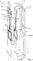
- Fig. 1 shows an exploded view of a sample cell 1 according to the invention.
- the sample cell 1 comprises a first plate 2, a second plate 3 and an NMR coil 4.
- the plates 2, 3 are basically rectangular and elongated in a long direction (here the vertical direction).
- each of the two plates 2, 3 have a (maximum) length LS of 50 mm, a (maximum) width WS of 10 mm and a (maximum) height HS of 1 mm; note that the example dimensions of LS, WS and HS are typical for a 10 GHz EPR microwave resonator.
- a cavity recess 5 is etched into the first plate 2 which forms a flat sample cavity 6; the cavity recess 5 is etched into the first plate 2 from the inner flat side facing the second plate 3.
- the flat sample cavity 6 is approximately cuboidally shaped with curved edges.
- two channel recesses 7 are etched into the first plate 2 which form two channels 8.
- the two channels 8 are positioned parallel and next to each other here. In the embodiment shown, the two channels 8 are shaped approximately cuboidally with a length of 20 mm, a width of 0.2 mm and a height of 0.2 mm.
- the channels 8 open into connections (inlet/outlet) for a liquid sample to be measured; the connections are simply called inlets here.
- First halves of the inlets 10a for the two channels 8 are formed in the first plate 2, wherein the two first halves of the inlets 10a are shaped semi-conical here.
- the two channels 8 are connected to the flat sample cavity 6 whereby the two channels 8 widen at the transition into the flat sample cavity 6.
- a coil recess 11 is etched into the second plate 3; the coil recess 11 is etched into the second plate 3 from the inner flat side facing the first plate 2.
- the coil recess 11 here also comprises two contact channels 11a, 11b for contact lines 14a, 14b to the NMR coil 4, wherein the contact lines 14a, 14b lead from contacts 13a, 13b to the NMR coil 4.
- the NMR coil 4 can be arranged in the coil recess 11 of the second plate 3.
- the NMR coil 4 is arranged on the side of the second plate 3 that faces the flat sample cavity 6 of the first plate 2.
- the contacts 13a, 13b for the NMR coil 4 are arranged on the outer side of the second plate 3 facing away from the first plate 2 and the sample cavity 6, in respective contact recesses 12 prepared on said outer side of the second plate 3.
- the NMR coil 4 comprises two conductor loops that are wound in a pancake type fashion.
- the NMR coil 4 may e.g. comprise more than two conductor loops or only one conductor loop (not shown).
- the NMR coil 4 is wound around a coil axis 4a.
- the coil axis 4a is centrally arranged inside the NMR coil 4 or its wound conductor loops.
- the NMR coil 4 is bridged in a bridging area 15 for contacting an inner end of the NMR coil 4, so that the NMR coil 4 or its wound conductor loops can be basically flat.
- the NMR coil 4 is arranged in the coil recess 11 of the second plate 3 via sputtering (i.e. the NMR coil 4 is built up directly inside the coil recess 11); the same applies to the contact lines 14a, 14b in the contact channels 11a, 11b.
- two second halves of inlets 10b are formed on an upper end 16 of the second plate 3 .
- the two second halves of inlets 10b are shaped semi-conical and form the counterpart to the two first halves of inlets 10a of the first plate 2.
- the two semi-conical halves of inlets 10a and the two semi-conical halves of inlets 10b form two conical inlets or connections for inserting and/or removing a liquid sample.
- the cavity recess 5 that forms the flat sample cavity 6 is enclosed between and sealed by the two plates 2, 3. Only then it will be possible to fill a liquid sample via the channels 8 into the sample cell 1.
- the conical form of the inlets or connections formed by the semi-conical halves of inlets 10a, 10b simplifies filling the liquid sample into the sample cell 1 or removing the liquid sample from the sample cell 1.
- the small size of the channels 8 prevents that impurities like dust may easily enter the flat sample cavity 6; in addition it minimizes a signal contribution from liquid sample that is not located inside the desired sample volume, i.e. in the flat sample cavity 6 (where the RF magnetic field is maximum and homogeneous). Furthermore, the small size of the channels 8 also prevents fast evaporation of the solvent of the liquid sample filled into the sample cell 1.
- the NMR coil 4 is enclosed between the two plates 2, 3.
- the (external) contacts 13 of the NMR coil 4 and a bridging contact 15a in the bridging area 15 for connecting the inner end of the NMR coil 4 with the contact line 14b and the contact 13b are arranged on the outer side of second plate 2 (i.e. on the side facing away from the first plate 2) here.
- the NMR coil 4, in particular its wound conductor loops, as well as the contact lines 14a, 14b are well protected from the environment. Thereby, the risk of damaging the NMR coil 4 or the contact lines 14a, 14b during sample preparation or during insertion of the sample cell 1 into a measurement device, and in particular into an NMR probe or a sample cell holder, is minimized.
- about 90% of the NMR coil cross-sectional area 17a is taken up by (or overlaps with) a sample cavity cross-sectional area 18 of the flat sample cavity 6, taken also perpendicular to the NMR coil axis 4a.
- a high filling factor of the NMR coil 4 is achieved. Due to the high filling factor of the NMR coil 4 a high strength NMR signal can be achieved.
- the NMR coil 4 that is wound around the flat sample cavity 6 generates an RF magnetic field B 2 , with the RF magnetic field B 2 basically parallel to the NMR coil axis 4a in an area of the flat sample cavity 6 (see Fig. 7 below).
- the recesses 5, 7, 11, 12 are made by etching.
- etching method laser-assisted micromachining is preferably used because this method offers various possibilities of creating different 3D structures.
- other etching methods like ion beam etching or dry etching may be used.
- fused silica is preferably used.
- borosilicate it is also possible to use borosilicate. Both fused silica and borosilicate are possible wafer materials for laser-assisted micromachining. Note that the invention is not restricted with respect to possible manufacturing methods of the sample cell 1; in particular, it may be possible to use 3D printing for preparing a sample cell 1 or its plates 2, 3.
- the cavity recess 5 can be formed in two parts, with a part in the first plate 2 and a part in the second plate 3, or the cavity recess 5 can be formed only in the second plate 3 (not shown).
- the coil recess 11 can be formed in two parts, with a part in the second plate 3 and a part in the first plate 2, or the coil recess 11 can be formed only in the first plate 2 (not shown).
- Fig. 2 depicts an enlarged view of the cavity recess 5 of the first plate 2 from the embodiment according to the invention of Fig. 1 .
- the cavity recess 5 forms the flat sample cavity 6.
- the flat sample cavity 6 is connected to the two channels 8.
- the flat sample cavity 6 is formed approximately cuboidally with curved edges.
- the flat sample cavity 6 has a maximum length L of 5 mm, a maximum width W of 5 mm and a maximum height H of 0.2 mm.
- the volume of the flat sample cavity 6 taking into account the curved edges results in an effective sample volume of 4.8 ⁇ l here.
- the flat sample cavity 6 basically extends along a sample cavity plane 19; the directions in which the maximum length L and the maximum width W extend are in parallel with the sample cavity plane 19, and the direction in which the maximum height H extends is perpendicular to the sample cavity plane 19.
- the sample cavity plane 19 is centred in the flat sample cavity 6 (see also Fig. 3 ).
- the flat sample cavity 6 can easily be positioned at and oriented parallel to a plane of zero electric field of the microwave radiation to avoid or at least minimize sample heating. At the same time the dimensions allow for an increased volume of the flat sample cavity 6.
- Fig. 3 a schematic longitudinal section of the sample cell 1 of Fig. 1 according to the invention in assembled form in the plane A there is shown.
- the sample cell 1 comprises the first plate 2 with the cavity recess 5 and the flat sample cavity 6, and the second plate 3 with the coil recess 11 and the NMR coil 4.
- the sample cavity plane 19 of the flat sample cavity 6 is shown as a dashed line.
- the sample cavity plane 19 is centrally arranged inside the flat sample cavity 6 with respect to a direction PD perpendicular to the sample cavity plane 19.
- PD perpendicular to the sample cavity plane 19.
- the sample cavity plane 19 is located at 0.1 mm in direction of H inside the flat sample cavity 6.
- the NMR coil 4 comprises two conductor loops arranged in the coil recess 11; note that the coil recess 11 is wound in accordance to the course of the NMR coil 4, and accordingly has two loops, too.
- the NMR coil 4 is drawn with oval cross-section of the corresponding conductor.
- the NMR coil 4 (with its wound conductor loops) is arranged basically along an NMR coil plane 17.
- the NMR coil plane 17 is parallel to the sample cavity plane 19, and is located centrally with respect to the NMR coil along the NMR coil axis 4a.
- the flat sample cavity 6 comprises a centre Point P CS .
- the centre point P CS is located in the centre of the sample cavity plane 19.
- the NMR coil 4 comprises a centre Point P NMR .
- the centre point P NMR is located in the centre of the NMR coil plane 17.
- An offset distance O d between the centre Point P CS and the centre point P NMR is about 0.12 mm here.
- the q factor of an ESR resonator using a sample cell as shown used during a DNP-NMR measurement may reach particularly high values when the offset distance O d is small. When a large q factor is achieved a better quality of the DNP-NMR measurements is achieved.
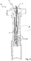
- Fig. 4 shows a schematic drawing of an NMR probe 20 according to the invention, in a view basically with the NMR probe 20 cut in half.
- the sample cell 1 is shown as whole.
- the NMR probe 20 comprises a sample cell holder 21 for inserting and removing the sample cell 1.
- the sample cell 1 is shown in an inserted state in the sample cell holder 21.
- the NMR probe 20 further comprises two sweeping coils 22.
- the sweeping coils 22 are arranged on both of the (flat) sides of the sample cell 1.
- the sweeping coils 22 run parallel to each other. Further, the sweeping coils 22 run parallel to the sample cavity plane of the flat sample cavity 6.
- the sweeping coils 22 generate a sweeping magnetic field.
- the sweeping magnetic field is parallel to the sample cavity plane in the area of the flat sample cavity 6 (see also Fig. 7 ).
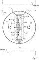
- FIG. 5 a schematic cross-section of the NMR probe 20 according to the invention from Fig. 4 in the plane B there is shown.
- the NMR probe 20 comprises the sample cell 1, the sample cell holder 21 and the two sweeping coils 22.
- the sample cell 1 is shown schematically with the first plate 2 comprising the flat sample cavity 6 filled with a liquid sample 23 (dotted area) and the second plate 3 comprising the coil recess (not shown here for simplification) containing the NMR coil 4.
- the sample cell holder 21 is formed with a dielectric sleeve 24.
- the dielectric sleeve 24 has an inner height HD of here 2 mm and an inner width WD of here 10 mm.
- An inner region 25 of the dielectric sleeve 24 extends with the inner height HD and the inner width WD and is shaped basically rectangular in cross-section with rounded corners.
- the maximum height HS of the sample cell 1 is 1 mm and the maximum width WS of the sample cell 1 is 10 mm in the example presented (see Fig. 1 ), which just fits into the dielectric sleeve 24.
- two tempering channels 26 are formed.
- the two tempering channels 26 are limited by the sample cell 1 and the dielectric sleeve 24 in cross-section.
- Each of the channels 26 has a height HT of here 0.5 mm.
- the two tempering channels 26 extend parallel to the flat sample cavity 6 and adjacent to the sample cell 1.
- the tempering channels 26 are used to vary and or to keep the temperature of the liquid sample 23 to be measured.
- the temperature of the tempering channel 26 is controlled via a tempering fluid flow (for example a gas stream or a liquid).
- a temperature control system (not shown) may be used for controlling the temperature of the liquid sample 23 or the tempering fluid flow, respectively.
- the sample cell holder 21 can be formed such that the sample cell 1 and the dielectric sleeve 24 form only one tempering channel 26 (not shown). Then preferably, the tempering channel 26 extends parallel to the flat sample cavity 6 on the side of the sample cell 1 closest to the flat sample cavity 6 (not shown) to ensure a good temperature control.
- the two sweeping coils 22 are rod-shaped with a circular cross-section.
- the sweeping coils 22 are of tube type. Coil wires (not shown) are included inside the sweeping coils 22.
- the sweeping coils 22 run parallel to the sample cavity plane and parallel to each other.
- an offset O s of the sweeping coils 22 is 6.5 mm and a maximum outer diameter d out of the sweeping coils 22 is 1 mm. In use, with such an outer diameter d out a relatively high q factor can be achieved, as compared to larger outer diameters d out .
- Fig. 6 depicts a schematic drawing of a DNP-NMR measuring device 27 (cut in half) according to the invention with an EPR microwave resonator 28 (cut in half) and the NMR probe 20 (cut in half) with the sample cell 1 inserted (and shown as whole and half transparent).
- the DNP-NMR measuring device 27 further comprises a magnet arrangement (not shown, but compare Fig. 7 ). In use, the magnet arrangement generates a B 0 magnetic field (see Fig. 7 ).
- the DNP-NMR measuring device 27 also comprises a microwave source 30 for generating microwave radiation and a waveguide 31 that guides the microwave radiation generated at the microwave source 30 to the EPR microwave resonator 28. Therefore, the microwave radiation is guided to an iris 32 and coupled into the EPR microwave resonator 28.
- a resonant volume VR of the EPR microwave resonator 28 encloses a cubic volume here with a length LR of 22.7 mm, a width WR of 11,5 mm and a height HR of 41.2 mm (note that the nomenclature here sticks to the allocation of letters L, W and H as for the flat sample cavity 6, and R indicates the resonator).
- the EPR microwave resonator 28 is operated in TE 102 mode with a microwave radiation having a resonance frequency of about 10 GHz here.
- a B 1 microwave magnetic field of the TE 102 mode is oriented perpendicular to the B 0 magnetic field in the area of the flat sample cavity 6 (see Fig. 7 ).
- the NMR probe 20 is inserted into the EPR microwave resonator 28 and fastened with clamping elements 33. About half of the NMR probe 20 is located inside the EPR microwave resonator 28.
- the flat sample cavity 6 and the NMR coil 4 of the inserted sample cell 1 are positioned centrally (and completely) in the EPR microwave resonator 28. There the microwave magnetic field B 1 peaks and the microwave electric field vanishes (i.e. is minimal) in the area of the flat sample cavity 6.
- the strength of the B 0 magnetic field generated by the magnet arrangement is here about 0.4 Tesla; note that a typical range for B 0 values is 0.2 to 2 Tesla. So the DNP-NMR measuring device 27 is a low field DNP-NMR measuring device 27. The DNP-NMR measuring device 27 is of benchtop size.
- Fig. 7 shows a simplified schematic cross-section of the NMR probe 20 from Fig. 4 in the plane B there with the directions and approximate positions, where applicable, of the different magnetic fields that are used, in particular generated and/or measured, during DNP-NMR measurements with the NMR probe 20 inserted into the EPR microwave resonator depicted in Fig. 6 .
- the NMR probe 20 comprises the sweeping coils 22, the sample cell holder 21 formed with a dielectric sleeve 24, the two tempering channels 26 and the sample cell 1.
- the sample cell 1 comprises the first plate 2 with the cavity recess for the flat sample cavity 6 and the second plate 3 with the coil recess for the NMR coil 4.
- the B 0 magnetic field is generated by the magnet arrangement 29 of the DNP-NMR measuring device.
- the magnet arrangement 29 comprises a permanent magnet and a ferromagnetic yoke encompassing the permanent magnet, with two pole shoes 29a, 29b attached to the yoke.
- the sample cell 1 is located and exposed to the static B 0 magnetic field established between the pole shoes 29a, 29b.
- Fig. 7 only the two pole shoes 29a, 29b are partially shown.
- the B 0 magnetic field is oriented parallel to the sample cavity plane 19 in the area of the flat sample cavity 6.
- the static B 0 magnetic field (together with the sweeping magnetic field B s , if applicable) is used to split the degenerate energy states of the nuclear spins of the sample to be measured, and to split degenerate energy states of spins of paramagnetic electrons in the sample to be measured.
- the sweeping magnetic field B S is generated by the sweeping coils 22 and is parallel to the B 0 magnetic field in the area of the flat sample cavity 6, in particular in order to adjust the energy split of the paramagnetic electrons to the microwave frequency.
- the sweeping magnetic field B S is parallel to the sample cavity plane 19 in the area of the flat sample cavity 6.
- the B 1 microwave magnetic field of TE 102 mode is generated by the microwave source. Inside the ESR resonator, a standing wave of microwave radiation is established, in accordance with said mode.
- the B 1 microwave magnetic field has a maximum in the area of the flat sample cavity 6, and is oriented parallel to the sample cavity plane 19 in the area of the flat sample cavity 6. Due to the geometry of the flat sample cavity 6, in particular its small height H (see Fig. 2 or 3 ), the sample to be measured is excited homogeneously by the B 1 microwave magnetic field. At the same time a plane of minimum electric field of TE 102 mode runs through the flat sample cavity 6. Due to the small height H of the flat sample cavity 6 the absorption of microwave electrical energy is low and thereby unwanted heating of the sample to be measured is low, too.
- the B 1 microwave magnetic field (which is in Fig. 7 perpendicular to the drawing plane) is oriented parallel to the sample cavity plane 19 in the area of the flat sample cavity 6 and perpendicular to the B 0 magnetic field and the sweeping magnetic field B S in the area of the flat sample cavity 6.
- the RF magnetic field B 2 is generated and/or measured by the NMR coil 4.
- the B 2 magnetic field is parallel to the NMR coil axis 4a, and further the B 2 magnetic field is perpendicular to the flat sample cavity 6 or its sample cavity plane 19, respectively, in the area of the sample cavity 6.
- the B 2 magnetic field is oriented perpendicular to the B 0 magnetic field and the sweeping magnetic field B S .
- the B 2 magnetic field is perpendicular to the B 1 microwave magnetic field in the area of the flat sample cavity 6; in other words, the NMR coil plane is parallel to the B 1 magnetic field, what minimizes interferences of the B 1 magnetic field and the B 2 magnetic field (or the NMR coil 4, respectively).
- the B 2 magnetic field excites and detects the nuclear spin transitions in the sample to be measured.
Landscapes
- Physics & Mathematics (AREA)
- General Physics & Mathematics (AREA)
- High Energy & Nuclear Physics (AREA)
- Condensed Matter Physics & Semiconductors (AREA)
- Biochemistry (AREA)
- Analytical Chemistry (AREA)
- Chemical & Material Sciences (AREA)
- General Health & Medical Sciences (AREA)
- Life Sciences & Earth Sciences (AREA)
- Immunology (AREA)
- Pathology (AREA)
- Health & Medical Sciences (AREA)
- Magnetic Resonance Imaging Apparatus (AREA)
- Control Of Motors That Do Not Use Commutators (AREA)
Abstract
for interchangeable use in an EPR microwave resonator (28),
with the sample cell (1) comprising
- a flat sample cavity (6) for holding a liquid (23) sample to be measured, wherein the flat sample cavity (6) extends with a maximum length L and a maximum width W in a sample cavity plane (19), and extends with a maximum height H perpendicular to the sample cavity plane (19), with H ≤ 1/15*L and H ≤ 1/15*W, and
- an NMR coil (4) wound around the flat sample cavity (6) for generating an RF magnetic field B2, wherein a coil axis (4a) of the NMR coil (4) about which the NMR coil (4) is wound is oriented perpendicular to the sample cavity plane (19). The invention provides a sample cell which is easy to handle and improves the quality and the reproducibility of DNP-NMR measurements.
Description
- The invention relates to a sample cell for performing DNP-NMR measurements, for interchangeable use in an EPR microwave resonator.
- Nuclear magnetic resonance (NMR) spectroscopy is a widely used and very important method in material science, chemistry and biology. Scientists use NMR spectroscopy to determine the structure and/or the dynamics of an examined sample or compound. However, one major problem of NMR spectroscopy is that NMR spectroscopy generally suffers from low sensitivity. The low sensitivity and the accompanying small signal intensities can for example be overcome by signal averaging to obtain a sufficiently high signal-to-noise ratio. However, signal averaging can be a time-consuming and cost-intensive process.
- Dynamic nuclear polarization (DNP) offers the possibility to enhance the NMR signal by orders of magnitude. In DNP the spin polarization from paramagnetic electrons is transferred to nuclei of the sample to be measured. The nuclear spins are aligned proportional to the extent that the electron spins are aligned, wherein the electron spin polarization is enhanced using microwave radiation. Accordingly, more nuclear spins in the sample become aligned as compared to the level that would result from the Boltzmann distribution in thermal equilibrium, so hyperpolarization of the sample is achieved. Due to the larger number of aligned nuclear spins the NMR signals are enhanced.
- DNP-NMR measurements are mainly carried out on solid-state samples, but it is also possible to carry out DNP-NMR measurements on liquid samples. For a DNP-NMR measurement of a liquid sample the liquid sample is typically filled in a sample tube. The sample to be measured is placed in an electron paramagnetic resonance (EPR) resonator. The sample is then irradiated with a microwave (MW) magnetic field (near or at the EPR) B1 of appropriate direction and amplitude, wherein the sample is in an appropriate static background magnetic field B0, to saturate the electron spin transition. At the same time, the nuclear spins are excited by an additional radio frequency (RF) magnetic field B2 and the corresponding RF answer of the sample or its nuclear spins is measured.
- During the measurement MW electrical energy is absorbed by the sample. In case of a liquid sample the absorption of the electrical energy leads to unwanted sample heating. This complicates obtaining quantitative and reproducible results and can lead to destruction of the sample. Additionally, the liquid sample in a classical sample tube can only be excited inhomogeneously since it extends over the homogeneous range of the magnetic MW field.
- Garcia et al., "L-band Overhauser dynamic nuclear polarization", Journal of Magnetic Resonance, 203 (2010), 138-143 (= reference D1) disclose a DNP instrument at 0.04 T using 1.1 GHz electron spin resonance (ESR) frequencies and 1.7 MHz 1H NMR frequencies. The DNP probe comprises a loop-gap resonator and the NMR and EPR circuits are housed in the same probe head. The NMR coil is wrapped around the EPR resonator. A sample cell, in this case a doty susceptibility plug, with up to 5 mm diameter is placed inside the overlapping region of the loop gap resonator and the NMR coil. The electron-nucleus coupling factor of a liquid sample has been determined.
- In Garcia, the coupling of the MW electric field has not been investigated, so the problem of heating the liquid sample remains unresolved. Also the efficiency of the NMR coil wrapped around the EPR resonator and thereby the efficiency of the NMR measurements is low because the NMR coil is located far away from the sample outside of the EPR resonator.
-
DE 10 2008 017 135 A1 (= reference D2) describes a dual resonance structure for DNP-NMR experiments. The dual resonance structure comprises a MW resonator for generating electromagnetic fields suitable for EPR and an RF resonator, namely a strip resonator, for generating electromagnetic fields suitable for NMR. One part of the strip resonator also forms a part of the MW resonator. In the area where the strip resonator also forms a part of the MW resonator a ring is placed directly onto the strip resonator. The ring is used to hold a liquid sample to be measured. - When using such a setup the ring has to be cleaned after each measurement to ensure that no residues of former measurements disturb the new measurements. Furthermore, depending on the solvent used for the measurement it may also happen that the solvent evaporates before the measurement has finished. Further, the filling factor of the RF resonator is small.
-
US 2016/0334476 A1 (= reference D3) depicts a tuneable static DNP probe comprising a coilform with a sample cavity. A NMR coil for performing NMR measurements is wrapped around the coilform. - With such a setup it is possible to measure liquid samples. However, the problem of sample heating of liquid samples has not been discussed here and again the efficiency of the NMR measurements is low because the NMR coil is located far away from the sample.
- There are sample cells for EPR measurements that are commercially available. Flat type EPR sample cells are for example shown on the webpage of the company SP Wilmad-LabGlass, Vineland (New Jersey, USA), compare https://www.wilmad-labglass.com/ProductList.aspx?t=206 of 16.04.2021 (= reference D4).
- An ESR spectrometer with a TE102 type resonator is described in the commercial publication "MiniScope MS 5000 ESR spectrometer with scientific grade performance" of magnettech GmbH, Berlin, DE, undated, downloaded 10.06.2021 (= reference D5).
- In summary, there are different attempts to improve DNP-NMR measurements. However, the problem of sample heating or inhomogeneous excitation of the sample often remains. The use of different DNP-NMR setups with different types of sample cells for different research groups renders a comparison of their results difficult. Moreover, the known DNP-NMR setups are often constructed such that the placement of the NMR coils is not ideal for the NMR measurements.
- It is the object of the present invention to provide a sample cell which is easy to handle and improves the quality and the reproducibility of DNP-NMR measurements.
- This object is achieved, in accordance with the invention, by a sample cell for performing DNP-NMR measurements,
for interchangeable use in an EPR microwave resonator,
with the sample cell comprising - a flat sample cavity for holding a liquid sample to be measured, wherein the flat sample cavity extends with a maximum length L and a maximum width W in a sample cavity plane, and extends with a maximum height H perpendicular to the sample cavity plane, with H ≤ 1/15*L and H ≤ 1/15*W, and
- an NMR coil wound around the flat sample cavity for generating an RF magnetic field B2, wherein a coil axis of the NMR coil about which the NMR coil is wound is oriented perpendicular to the sample cavity plane.
- As an overview, the present invention proposes a sample cell with a flat sample cavity and an NMR coil wound around the flat sample cavity, which is directly arranged at the sample cell, which is designed to be exchanged (together with the sample) at an EPR microwave resonator.
- The sample cell is designed in such a way that the q factor of the EPR microwave resonator is affected as little as possible, i.e. may remain high with the sample cell inserted. The q factor (also called quality factor) is a dimensionless parameter that describes the dampening of a resonator; the lower the dampening, the higher is the q factor. The measurement quality for DNP-NMR measurements can be improved when the q factor is large.
- Furthermore, the sample cell is dimensioned such that, when the sample cell is positioned inside an EPR microwave resonator during a DNP-NMR measurement, the liquid sample filled into the sample cell may be located practically completely in a region of low MW electric field; this is achieved by a flat sample cavity, which can be arranged in a basically plane shaped maximum of the MW magnetic field, which corresponds to a basically plane shaped minimum of the MW electric field. In this way the MW magnetic field irradiates the liquid sample and saturates the electron spin transition while the absorption of MW electrical energy by the liquid sample is minimized. Thereby, the quality of the DNP-NMR measurements can be improved, the dielectric losses as well as the heating of the liquid sample can be minimized and the measurements can be performed at stable temperatures. Also sample decomposition due to increased temperatures of the liquid sample can be prevented and the reproducibility of the measurements can be improved.
- Further, by arranging the NMR coil on the interchangeable sample cell, the NMR coil can be located very close to the flat sample cavity and in this way the sample, and the inner region of the NMR coil can be filled to a large extent with the liquid sample. This results in a high NMR signal intensity.
- The sample cell can be easily exchanged at an ESR resonator and is inexpensive to produce, so that it can be used as a consumable, if desired. Thereby, cross-contaminations between samples do not occur. The sample cell is suitable for mass production and widespread use throughout different laboratories, what helps to increase comparability of measurement results.
- In more detail, the flat sample cavity has typically a circular or an ellipsoidal or a rectangular cross-section (in the sample cavity plane) and a very small thickness (perpendicular to the sample cavity plane). The q factor depends, among other things, on the thickness of the flat sample cavity. A flat sample cavity with a small thickness can be aligned easier with the maximum of the MW magnetic field and the minimum of the MW electric field inside an EPR microwave resonator. By choosing a small thickness of the flat sample cavity the q factor reaches a larger value and heating of the liquid sample can be minimized.
- Preferably, the cross-section of the flat sample cavity in the sample cavity plane is shaped substantially quadratically or substantially rectangularly, and the flat sample cavity is formed substantially cuboidally. With a flat sample cavity formed in such a manner comparably large sample volumes can be arranged in a homogenous region of the B1 field of an EPR resonator, and in a region of low MV electric field strength of the EPR resonator.
- A typical maximum height H of the flat sample cavity is H≤0.5mm or even H≤0.3mm. Also typically, H≤1/20*L and H≤1/20*W. The transverse dimensions, i.e. the maximum length L and the maximum width W, are typically given by the available space inside the EPR microwave resonator (also called EPR cavity). The longitudinal dimension (thickness, maximum height H) is determined (limited) by the EPR wavelength (microwave wavelength) λ, typically with H ≤ λ/10.
- During measurement, the sample cell is oriented with its sample cavity plane (also called transverse plane, in which L and W extend) along a plane of minimum electric field of the applied microwave mode. In this way the heating of the liquid sample caused by the MW electrical energy can be minimized. The sample cavity plane is centrally arranged inside the flat sample cavity with respect to the direction perpendicular to the sample cavity plane.
- The sample cell preferably is basically plate shaped, wherein the sample cell extends with a maximum length LS and a maximum width WS in the sample cavity plane, wherein LS ≥ WS, preferably LS ≥ 4*WS, wherein the sample cell extends with a maximum height HS perpendicular to the sample cavity plane, wherein HS < LS and HS < WS, in particular HS < 1/10*LS and HS < 1/10*WS, and wherein for the height HS of the sample cell, the following applies: HS ≤ 2.5 mm, preferably HS ≤ 1.5 mm, most preferably HS ≤ 1.0 mm. Such sample cells can be easily manufactured and the dimensions can be suitable to provide enough stability to the sample cell with the flat sample cavity. Further, such sample cells are easy to handle and can simply be inserted into an EPR microwave resonator.
- Preferably, the sample cell comprises two channels for filling the liquid sample into the flat sample cavity or to remove the liquid sample from the flat sample cavity, in particular wherein the channels are positioned next to each other. In this way the liquid sample can be easily filled into or removed from the sample cell. Additionally, only a fraction of the flat sample cavity is exposed to the environment which can reduce the entry of impurities and lower the evaporation of the solvent of the liquid sample.
- The (internal) NMR coil wound around the flat sample cavity generates an additional RF magnetic field B2. The NMR coil allows simultaneous excitation and measurement of the nuclear spins of the sample to be measured. The shape and the orientation of the NMR coil are chosen such that the interference with the MW field is minimized. Furthermore, the best q factors are received when the plane of the NMR coil and the sample cavity plane are as close together as possible.
- Typically, at least 70%, preferably at least 80%, most preferably at least 90 % of an inner area confined by the NMR coil is taken up by a cross-section of the flat sample cavity in the sample cavity plane. Due to the high filling factor of the NMR coil the signal strength of the NMR signal can be amplified. Preferably, the NMR coil comprises two conductor loops. Typically, the two loops are wound in a pancake type fashion. In other embodiments, the NMR coil may comprise even more than two conductor loops.
- A preferred embodiment of the inventive sample cell is characterized in
that the sample cell comprises a first plate and a second plate,
that the flat sample cavity is formed by a cavity recess in the first plate and/or a cavity recess in the second plate,
and that the first plate and second plate are joined to each other, with the flat sample cavity enclosed between them. This is an easy and cost-effective way to manufacture the sample cell. The cavity recess and thereby the geometry of the flat sample cavity can be freely designed (in particular depending on the planned measurement experiment). The cavity recess can for example be etched by laser-assisted micromachining. Fused silica or borosilicate can be used as a material for the plates (both are suitable for laser-assisted micromachining). - In a preferred development of this embodiment, a coil recess is formed in the first plate and/or a coil recess is formed in the second plate, wherein the NMR coil is arranged in the coil recess of the first plate and/or the coil recess of the second plate, in particular wherein the NMR coil is enclosed between the fist plate and the second plate. This is an easy and cost-effective way to integrate the NMR coil into the sample cell. The geometry of the coil recess and thereby the geometry of the NMR coil can be adapted to the cavity recess, in particular such that a large filling factor of the NMR coil is achieved. Sputtering can be used to produce the NMR coil. When joining the first plate and the second plate with the NMR coil arranged ("sandwiched") between them the NMR coil is protected inside the two plates and the risk of damaging the NMR coil can be minimized, e.g. if the sample cell is inserted into a holder. Furthermore, the flat sample cavity and the NMR coil can be brought into close proximity which improves the quality of DNP-NMR measurements. The coil recess can for example be etched by laser-assisted micromachining.
- In another preferred further development,
the flat sample cavity is formed only by a cavity recess of the first plate, and only the second plate forms a coil recess, in which the NMR coil is arranged. In this way the production of the sample cell can be further simplified. The cavity recess only has to be etched into the first plate and the coil recess only has to be etched into the second plate. The two plates can then be joined in an uncomplicated way. - In an advantageous embodiment of the sample cell, for an offset distance Od between a centre point PNMR of the NMR coil and a centre point PCS of the flat sample cavity, taken along the direction perpendicular of the sample cavity plane, the following applies:
Od ≤ 0.5 mm, preferably Od ≤ 0.35 mm, more preferably Od ≤ 0.2 mm, most preferably Od=0. - In other words, the NMR coil and the flat sample cavity are in close proximity with respect to the direction perpendicular to the sample cavity plane. The offset distance Od affects the q factor. The q factor generally reaches its highest value when the offset distance Od is minimal. Accordingly, with a small Od, a large q factor is achieved, thereby achieving a better quality of the NMR measurements.
- Another advantageous embodiment of the sample cell is characterized in that the maximum length L of the flat sample cavity is 3 mm ≤ L ≤ 7 mm, preferably 4 mm ≤ L ≤ 6 mm, most preferably L = 5 mm, that the maximum width W of the flat sample cavity is 3 mm ≤ W ≤ 7 mm, preferably 4 mm ≤ L ≤ 6 mm, most preferably W = 5 mm, and that the maximum height H of the flat sample cavity is 0.12 mm ≤ H ≤ 0.36 mm, preferably 0.15 mm ≤ H ≤ 0.25, most preferably H = 0.2 mm. These are dimensions that have been proven in practice. The flat sample cavity forms a comparably large sample volume that can be arranged in an EPR microwave resonator. Furthermore, the height H of the sample affects the q factor. Better q factors can in general be achieved when the height H is small.
- The scope of the present invention also includes an NMR probe for performing DNP-NMR measurements,
for use in an EPR microwave resonator,
with the NMR probe comprising - an inventive sample cell as described above,
- a sample cell holder for reversible insertion of the sample cell,
wherein the sample cell is inserted into the sample cell holder, and - two sweeping coils for generating a sweeping magnetic field which is substantially parallel to the sample cavity plane in the area of the flat sample cavity of the inserted sample cell. Such an NMR probe can easily be used with an EPR microwave resonator. The sample cell can simply be inserted and taken out of the sample cell holder for changing the measurement sample; for this purpose it is possible to fill and to empty the sample cell outside the NMR probe conveniently. The sweeping magnetic field, which during measurement is substantially parallel to the static magnetic field B0 in the area of the flat sample cavity, is (basically) perpendicular to the RF magnetic field B2 of the NMR coil in the area of the flat sample cavity. Typically, the two sweeping coils are arranged on both sides of the sample cell.
- In a preferred embodiment of the NMR probe, with the sample cell inserted into the sample cell holder, the NMR probe forms at least one tempering channel for varying and/or keeping a temperature of the liquid sample to be measured, in particular wherein at least in a region of the flat sample cavity, the at least one tempering channel extends parallel to the flat sample cavity and adjacent to the sample cell. This poses a simple way to control the temperature of the liquid sample. When the temperature is kept constant, the quality of the measurements can be improved. In use, a tempering fluid flow (typically a gas flow) is fed through the tempering channel. When there is only one tempering channel, the tempering channel preferably extends on the side of the sample cell closest to the flat sample cavity. Preferably, with the sample cell inserted, there is a tempering channel on both sides of the sample cell. A temperature control system may be used for controlling the temperature of the sample via the tempering fluid flow.
- In a preferred development of this embodiment, the NMR probe comprises a dielectric sleeve, wherein the dielectric sleeve at least partially limits the at least one tempering channel,
in particular wherein an inner region of the dielectric sleeve is subdivided into two tempering channels with the sample cell inserted in the sample cell holder. - With the dielectric sleeve, a tempering channel or channels can be formed particularly easily. The dielectric sleeve may be contain or may be made from polyethylene or ceramics. By using two tempering channels the temperature control can be further improved.
- An advantageous embodiment of the NMR probe is characterized in that the two sweeping coils are rod-shaped, in particular with a circular cross-section each, that the two sweeping coils are running parallel to each other,
and that the two sweeping coils are running parallel to the sample cavity plane. The form and the arrangement of the sweeping coils has been proven in practice. - A maximum outer diameter dout of the sweeping coils affects the q factor. The q factor increases when the outer diameter dout of the sweeping coils decreases in size. Typically, for the maximum outer diameter dout of the rod-shaped sweeping coils applies dout ≤ 2.0 mm, preferably dout ≤ 1.5 mm, most preferably dout ≤ 1.0 mm, and/or dout ≥ 0.3 mm, preferably dout ≥ 0.4 mm, most preferably dout ≥ 0.5 mm. Typically the rod-shaped sweeping coils are of tube type with a coil wire included inside.
- The scope of the invention furthermore includes a DNP-NMR measuring device comprising
- an EPR microwave resonator,
- an NMR probe as described above,
wherein the NMR probe is positioned at least partially inside the EPR microwave resonator such that the flat sample cavity and the NMR coil of the sample cell inserted into the sample cell holder are positioned inside the EPR microwave resonator, - a magnet arrangement for generating a B0 magnetic field which is parallel to the sweeping magnetic field and parallel to the sample cavity plane in the area of the flat sample cavity of the inserted sample cell. This is an easy to implement set-up to perform DNP-NMR measurements. It is possible to use existing EPR microwave resonators for the DNP-NMR measuring device easily. The EPR microwave resonator can achieve a high q factor with the inventive NMR probe and the inventive sample cell inserted. The B0 magnetic field is perpendicular to the RF magnetic field B2 (in the area of the flat sample cavity). Typically, the EPR microwave resonator is operated with a microwave radiation having a microwave frequency of between 8 GHz and 90 GHz. Typically, the magnet arrangement is designed and configured for generating a B0 magnetic field of 0.2 - 2 Tesla; accordingly, the DNP-NMR measuring device is a low field DNP-NMR measuring device then. A typical DNP-NMR measuring device is of benchtop size, having a good NMR signal intensity by means of the invention.
- In a preferred embodiment of the DNP-NMR measuring device, the EPR microwave resonator is dimensioned and configured for a particular microwave mode, wherein the sample cell is positioned such that
- a B1 microwave magnetic field of said particular microwave mode is oriented basically perpendicular to the B0 magnetic field in the area of the flat sample cavity, and
- the sample cavity plane is oriented along a plane of minimum electric field of said particular microwave mode, wherein the plane of minimum electric field of said particular microwave mode runs through the flat sample cavity. In this way the irradiation of the liquid sample in the flat sample cavity via the B1 microwave magnetic field can be maximized. Typically, the angle between the B1 microwave magnetic field and the B0 magnetic field in the area of the flat sample cavity deviates at maximum by 10° from 90°. Said particular microwave mode exhibits a plane of minimum of the electric field, typically located between two neighbouring maxima of the electric field, and the sample cavity plane at least approximately coincides with said plane of minimum electric field. So the electric field of said particular microwave mode has a minimum in the area of the flat sample cavity. In this way the absorption of microwave electrical energy by the liquid sample is minimized.
- In a preferred development of this embodiment, the B1 microwave magnetic field of said particular microwave mode is oriented basically parallel to the sample cavity plane in the area of the flat sample cavity. Accordingly, in this further development, the B1 magnetic field and RF magnetic field B2 are basically perpendicular in the area of the flat sample cavity. This arrangement has been proven in practice. The exposure of the sample to the MW electric field is therefore minimized. Typically, the angle between the B1 microwave magnetic field and sample cavity plane in the area of the flat sample cavity deviates at maximum by 10° from 0°. Correspondingly, the angle between the B1 microwave magnetic field and the B2 magnetic field in the area of the flat sample cavity deviates at maximum by 10° from 90°.
- In an advantageous embodiment of the DNP-NMR measuring device, the EPR microwave resonator is dimensioned and configured for microwave mode TE102. Such a microwave resonator has been proven in practice and can be used well with the NMR probe. In particular, the TE102 mode has a central plane of minimum MW electric field at which the sample cell can be placed conveniently.
- In another advantageous embodiment of the DNP-NMR measuring device,
the DNP-NMR measuring device further comprises - a microwave source,
- a waveguide for guiding microwave radiation to the EPR microwave resonator,
- and an iris for coupling the microwave radiation from the waveguide into the EPR microwave resonator. With such a set-up the microwave radiation can easily be fed into the EPR microwave resonator. Such a set-up has been proven in practice. The different parts of the measuring device are commercially available and thereby are easily accessible.
- The scope of the invention also includes the use of a sample cell as described above or an NMR probe as described above or a DNP measuring device as described above in a DNP-NMR measurement. The DNP-NMR measurements can achieve a high NMR signal strength. The EPR microwave resonator can reach high q factors with the sample cell or the NMR probe inserted. The liquid sample filled into the sample cell may be located practically completely in a region of high MW magnetic field and low MW electric field. In this way the excitation via the MW magnetic field is maximized while sample heating caused by the MW electric field is minimized. Further, the sample cell can be exchanged. Also a high filling factor of the NMR coil wound around the flat sample cavity can be achieved, which leads to a large NMR signal. The microwave frequency of the microwave radiation is typically chosen such that for the microwave wavelength λ, the following applies: H≤λ/10. The orientation of the sample cell in the EPR microwave resonator is chosen such that in the area of the flat sample cavity, B0 is (basically) perpendicular to B2, and B0 is (basically) perpendicular to B1. Often further B2 is (basically) perpendicular to B1 in the area of the flat sample cavity.
- Further advantages can be extracted from the description and the enclosed drawing. The features mentioned above and below can be used in accordance with the invention either individually or collectively in any combination. The embodiments mentioned are not to be understood as exhaustive enumeration but rather have exemplary character for the description of the invention.
- The invention is shown in the drawing.
- Fig. 1
- shows an exploded view of an embodiment of a sample cell according to the invention, with two plates, a coil recess, a cavity recess and an NMR coil;
- Fig. 2
- shows an enlarged view of the first plate of
Fig. 1 in the area of the cavity recess; - Fig. 3
- shows a schematic longitudinal section of the sample cell from
Fig. 1 in assembled form in the plane A there; - Fig. 4
- shows a schematic, partially sectional drawing of an embodiment of an NMR probe according to the invention, with the sample cell of
Fig. 1 inserted in a sample cell holder and two sweeping coils; - Fig. 5
- shows a schematic cross-section of the NMR probe from
Fig. 4 in the plane B there; - Fig. 6
- shows a schematic, partially sectional drawing of an embodiment of an DNP-NMR measuring device according to the invention, with an EPR microwave resonator and the NMR probe of
Fig. 4 inserted; - Fig. 7
- shows a simplified schematic cross-section of the NMR probe from
Fig. 4 in the plane B there, with the directions and approximate positions of the different magnetic fields that are used during DNP-NMR measurements. -
Fig. 1 shows an exploded view of asample cell 1 according to the invention. Thesample cell 1 comprises afirst plate 2, asecond plate 3 and anNMR coil 4. Theplates plates - A cavity recess 5 is etched into the
first plate 2 which forms aflat sample cavity 6; the cavity recess 5 is etched into thefirst plate 2 from the inner flat side facing thesecond plate 3. Theflat sample cavity 6 is approximately cuboidally shaped with curved edges. Furthermore, two channel recesses 7 are etched into thefirst plate 2 which form twochannels 8. The twochannels 8 are positioned parallel and next to each other here. In the embodiment shown, the twochannels 8 are shaped approximately cuboidally with a length of 20 mm, a width of 0.2 mm and a height of 0.2 mm. At anupper end 9 of thefirst plate 2, thechannels 8 open into connections (inlet/outlet) for a liquid sample to be measured; the connections are simply called inlets here. First halves of theinlets 10a for the twochannels 8 are formed in thefirst plate 2, wherein the two first halves of theinlets 10a are shaped semi-conical here. The twochannels 8 are connected to theflat sample cavity 6 whereby the twochannels 8 widen at the transition into theflat sample cavity 6. - A
coil recess 11 is etched into thesecond plate 3; thecoil recess 11 is etched into thesecond plate 3 from the inner flat side facing thefirst plate 2. Thecoil recess 11 here also comprises twocontact channels contact lines NMR coil 4, wherein thecontact lines contacts NMR coil 4. TheNMR coil 4 can be arranged in thecoil recess 11 of thesecond plate 3. TheNMR coil 4 is arranged on the side of thesecond plate 3 that faces theflat sample cavity 6 of thefirst plate 2. Thecontacts NMR coil 4 are arranged on the outer side of thesecond plate 3 facing away from thefirst plate 2 and thesample cavity 6, in respective contact recesses 12 prepared on said outer side of thesecond plate 3. In the example shown, theNMR coil 4 comprises two conductor loops that are wound in a pancake type fashion. In an alternative embodiment theNMR coil 4 may e.g. comprise more than two conductor loops or only one conductor loop (not shown). - The
NMR coil 4 is wound around acoil axis 4a. Thecoil axis 4a is centrally arranged inside theNMR coil 4 or its wound conductor loops. TheNMR coil 4 is bridged in abridging area 15 for contacting an inner end of theNMR coil 4, so that theNMR coil 4 or its wound conductor loops can be basically flat. Typically, theNMR coil 4 is arranged in thecoil recess 11 of thesecond plate 3 via sputtering (i.e. theNMR coil 4 is built up directly inside the coil recess 11); the same applies to thecontact lines contact channels - On an
upper end 16 of thesecond plate 3 two second halves ofinlets 10b are formed. The two second halves ofinlets 10b are shaped semi-conical and form the counterpart to the two first halves ofinlets 10a of thefirst plate 2. In an assembled form of thesample cell 1 the two semi-conical halves ofinlets 10a and the two semi-conical halves ofinlets 10b form two conical inlets or connections for inserting and/or removing a liquid sample. - When the two
plates flat sample cavity 6 is enclosed between and sealed by the twoplates channels 8 into thesample cell 1. The conical form of the inlets or connections formed by the semi-conical halves ofinlets sample cell 1 or removing the liquid sample from thesample cell 1. The small size of thechannels 8 prevents that impurities like dust may easily enter theflat sample cavity 6; in addition it minimizes a signal contribution from liquid sample that is not located inside the desired sample volume, i.e. in the flat sample cavity 6 (where the RF magnetic field is maximum and homogeneous). Furthermore, the small size of thechannels 8 also prevents fast evaporation of the solvent of the liquid sample filled into thesample cell 1. - Further, in the joined form the
NMR coil 4 is enclosed between the twoplates NMR coil 4 and abridging contact 15a in the bridgingarea 15 for connecting the inner end of theNMR coil 4 with thecontact line 14b and thecontact 13b are arranged on the outer side of second plate 2 (i.e. on the side facing away from the first plate 2) here. TheNMR coil 4, in particular its wound conductor loops, as well as thecontact lines NMR coil 4 or thecontact lines sample cell 1 into a measurement device, and in particular into an NMR probe or a sample cell holder, is minimized. - An NMR coil
cross-sectional area 17a, taken perpendicular to theNMR coil axis 4a, is confined by theNMR coil 4. Here, in the joined form of thesample cell 1, about 90% of the NMR coilcross-sectional area 17a is taken up by (or overlaps with) a sample cavity cross-sectional area 18 of theflat sample cavity 6, taken also perpendicular to theNMR coil axis 4a. Thereby, a high filling factor of theNMR coil 4 is achieved. Due to the high filling factor of theNMR coil 4 a high strength NMR signal can be achieved. In use, theNMR coil 4 that is wound around theflat sample cavity 6 generates an RF magnetic field B2, with the RF magnetic field B2 basically parallel to theNMR coil axis 4a in an area of the flat sample cavity 6 (seeFig. 7 below). - The
recesses plates sample cell 1; in particular, it may be possible to use 3D printing for preparing asample cell 1 or itsplates - In alternative embodiments, the cavity recess 5 can be formed in two parts, with a part in the
first plate 2 and a part in thesecond plate 3, or the cavity recess 5 can be formed only in the second plate 3 (not shown). Further thecoil recess 11 can be formed in two parts, with a part in thesecond plate 3 and a part in thefirst plate 2, or thecoil recess 11 can be formed only in the first plate 2 (not shown). -
Fig. 2 depicts an enlarged view of the cavity recess 5 of thefirst plate 2 from the embodiment according to the invention ofFig. 1 . The cavity recess 5 forms theflat sample cavity 6. Theflat sample cavity 6 is connected to the twochannels 8. - Here the
flat sample cavity 6 is formed approximately cuboidally with curved edges. In the embodiment shown, theflat sample cavity 6 has a maximum length L of 5 mm, a maximum width W of 5 mm and a maximum height H of 0.2 mm. The volume of theflat sample cavity 6 taking into account the curved edges results in an effective sample volume of 4.8 µl here. - The
flat sample cavity 6 basically extends along asample cavity plane 19; the directions in which the maximum length L and the maximum width W extend are in parallel with thesample cavity plane 19, and the direction in which the maximum height H extends is perpendicular to thesample cavity plane 19. Thesample cavity plane 19 is centred in the flat sample cavity 6 (see alsoFig. 3 ). - Basically, with such a geometry of the
flat sample cavity 6 and thesample cell 1, during a DNP-NMR measurement theflat sample cavity 6 can easily be positioned at and oriented parallel to a plane of zero electric field of the microwave radiation to avoid or at least minimize sample heating. At the same time the dimensions allow for an increased volume of theflat sample cavity 6. - In
Fig. 3 a schematic longitudinal section of thesample cell 1 ofFig. 1 according to the invention in assembled form in the plane A there is shown. Thesample cell 1 comprises thefirst plate 2 with the cavity recess 5 and theflat sample cavity 6, and thesecond plate 3 with thecoil recess 11 and theNMR coil 4. - In
Fig. 3 , the dimensions LS and HS of thesample cell 1 and L and H of theflat sample cavity 6 are indicated again; note that for the purpose of better visibility the proportions of L to H and LS to HS are not to scale here. - In the
first plate 2 thesample cavity plane 19 of theflat sample cavity 6 is shown as a dashed line. Thesample cavity plane 19 is centrally arranged inside theflat sample cavity 6 with respect to a direction PD perpendicular to thesample cavity plane 19. As the height H of theflat sample cavity 6 is 0.2 mm this means that thesample cavity plane 19 is located at 0.1 mm in direction of H inside theflat sample cavity 6. - Arranged in the
second plate 3, theNMR coil 4 comprises two conductor loops arranged in thecoil recess 11; note that thecoil recess 11 is wound in accordance to the course of theNMR coil 4, and accordingly has two loops, too. For simplicity, theNMR coil 4 is drawn with oval cross-section of the corresponding conductor. In the example shown, the NMR coil 4 (with its wound conductor loops) is arranged basically along anNMR coil plane 17. TheNMR coil plane 17 is parallel to thesample cavity plane 19, and is located centrally with respect to the NMR coil along theNMR coil axis 4a. - The
flat sample cavity 6 comprises a centre Point PCS. The centre point PCS is located in the centre of thesample cavity plane 19. Furthermore, theNMR coil 4 comprises a centre Point PNMR. The centre point PNMR is located in the centre of theNMR coil plane 17. An offset distance Od between the centre Point PCS and the centre point PNMR is about 0.12 mm here. Generally, the q factor of an ESR resonator using a sample cell as shown used during a DNP-NMR measurement may reach particularly high values when the offset distance Od is small. When a large q factor is achieved a better quality of the DNP-NMR measurements is achieved. -
Fig. 4 shows a schematic drawing of anNMR probe 20 according to the invention, in a view basically with theNMR probe 20 cut in half. Thesample cell 1 is shown as whole. - The
NMR probe 20 comprises asample cell holder 21 for inserting and removing thesample cell 1. Here, thesample cell 1 is shown in an inserted state in thesample cell holder 21. - The
NMR probe 20 further comprises twosweeping coils 22. The sweeping coils 22 are arranged on both of the (flat) sides of thesample cell 1. The sweeping coils 22 run parallel to each other. Further, thesweeping coils 22 run parallel to the sample cavity plane of theflat sample cavity 6. In use thesweeping coils 22 generate a sweeping magnetic field. The sweeping magnetic field is parallel to the sample cavity plane in the area of the flat sample cavity 6 (see alsoFig. 7 ). - In
Fig. 5 a schematic cross-section of theNMR probe 20 according to the invention fromFig. 4 in the plane B there is shown. TheNMR probe 20 comprises thesample cell 1, thesample cell holder 21 and the twosweeping coils 22. Thesample cell 1 is shown schematically with thefirst plate 2 comprising theflat sample cavity 6 filled with a liquid sample 23 (dotted area) and thesecond plate 3 comprising the coil recess (not shown here for simplification) containing theNMR coil 4. - Here the
sample cell holder 21 is formed with adielectric sleeve 24. Thedielectric sleeve 24 has an inner height HD of here 2 mm and an inner width WD of here 10 mm. Aninner region 25 of thedielectric sleeve 24 extends with the inner height HD and the inner width WD and is shaped basically rectangular in cross-section with rounded corners. The maximum height HS of thesample cell 1 is 1 mm and the maximum width WS of thesample cell 1 is 10 mm in the example presented (seeFig. 1 ), which just fits into thedielectric sleeve 24. - With the
sample cell 1 centrally inserted into thedielectric sleeve 24, two temperingchannels 26 are formed. The twotempering channels 26 are limited by thesample cell 1 and thedielectric sleeve 24 in cross-section. Each of thechannels 26 has a height HT of here 0.5 mm. The twotempering channels 26 extend parallel to theflat sample cavity 6 and adjacent to thesample cell 1. - The tempering
channels 26 are used to vary and or to keep the temperature of the liquid sample 23 to be measured. In use, the temperature of the temperingchannel 26 is controlled via a tempering fluid flow (for example a gas stream or a liquid). A temperature control system (not shown) may be used for controlling the temperature of the liquid sample 23 or the tempering fluid flow, respectively. When DNP-NMR measurements are performed the temperature of the liquid sample 23 to be measured is stabilized by the tempering fluid flow during microwave irradiation. Thereby, it is possible to produce comparable and reproducible results. - Alternatively, the
sample cell holder 21 can be formed such that thesample cell 1 and thedielectric sleeve 24 form only one tempering channel 26 (not shown). Then preferably, the temperingchannel 26 extends parallel to theflat sample cavity 6 on the side of thesample cell 1 closest to the flat sample cavity 6 (not shown) to ensure a good temperature control. - In the embodiment shown, the two
sweeping coils 22 are rod-shaped with a circular cross-section. The sweeping coils 22 are of tube type. Coil wires (not shown) are included inside thesweeping coils 22. The sweeping coils 22 run parallel to the sample cavity plane and parallel to each other. Here, an offset Os of thesweeping coils 22 is 6.5 mm and a maximum outer diameter dout of thesweeping coils 22 is 1 mm. In use, with such an outer diameter dout a relatively high q factor can be achieved, as compared to larger outer diameters dout. -
Fig. 6 depicts a schematic drawing of a DNP-NMR measuring device 27 (cut in half) according to the invention with an EPR microwave resonator 28 (cut in half) and the NMR probe 20 (cut in half) with thesample cell 1 inserted (and shown as whole and half transparent). - The DNP-
NMR measuring device 27 further comprises a magnet arrangement (not shown, but compareFig. 7 ). In use, the magnet arrangement generates a B0 magnetic field (seeFig. 7 ). The DNP-NMR measuring device 27 also comprises amicrowave source 30 for generating microwave radiation and awaveguide 31 that guides the microwave radiation generated at themicrowave source 30 to theEPR microwave resonator 28. Therefore, the microwave radiation is guided to aniris 32 and coupled into theEPR microwave resonator 28. - A resonant volume VR of the
EPR microwave resonator 28 encloses a cubic volume here with a length LR of 22.7 mm, a width WR of 11,5 mm and a height HR of 41.2 mm (note that the nomenclature here sticks to the allocation of letters L, W and H as for theflat sample cavity 6, and R indicates the resonator). In use, theEPR microwave resonator 28 is operated in TE102 mode with a microwave radiation having a resonance frequency of about 10 GHz here. A B1 microwave magnetic field of the TE102 mode is oriented perpendicular to the B0 magnetic field in the area of the flat sample cavity 6 (seeFig. 7 ). - The
NMR probe 20 is inserted into theEPR microwave resonator 28 and fastened with clampingelements 33. About half of theNMR probe 20 is located inside theEPR microwave resonator 28. Theflat sample cavity 6 and theNMR coil 4 of the insertedsample cell 1 are positioned centrally (and completely) in theEPR microwave resonator 28. There the microwave magnetic field B1 peaks and the microwave electric field vanishes (i.e. is minimal) in the area of theflat sample cavity 6. - The strength of the B0 magnetic field generated by the magnet arrangement is here about 0.4 Tesla; note that a typical range for B0 values is 0.2 to 2 Tesla. So the DNP-
NMR measuring device 27 is a low field DNP-NMR measuring device 27. The DNP-NMR measuring device 27 is of benchtop size. -
Fig. 7 shows a simplified schematic cross-section of theNMR probe 20 fromFig. 4 in the plane B there with the directions and approximate positions, where applicable, of the different magnetic fields that are used, in particular generated and/or measured, during DNP-NMR measurements with theNMR probe 20 inserted into the EPR microwave resonator depicted inFig. 6 . - The
NMR probe 20 comprises thesweeping coils 22, thesample cell holder 21 formed with adielectric sleeve 24, the two temperingchannels 26 and thesample cell 1. Thesample cell 1 comprises thefirst plate 2 with the cavity recess for theflat sample cavity 6 and thesecond plate 3 with the coil recess for theNMR coil 4. - During DNP-NMR measurements four different magnetic fields are of relevance:
The B0 magnetic field is generated by themagnet arrangement 29 of the DNP-NMR measuring device. In the chosen embodiment, themagnet arrangement 29 comprises a permanent magnet and a ferromagnetic yoke encompassing the permanent magnet, with twopole shoes pole shoes sample cell 1 is located and exposed to the static B0 magnetic field established between thepole shoes Fig. 7 , only the twopole shoes sample cavity plane 19 in the area of theflat sample cavity 6. The static B0 magnetic field (together with the sweeping magnetic field Bs, if applicable) is used to split the degenerate energy states of the nuclear spins of the sample to be measured, and to split degenerate energy states of spins of paramagnetic electrons in the sample to be measured. - The sweeping magnetic field BS is generated by the
sweeping coils 22 and is parallel to the B0 magnetic field in the area of theflat sample cavity 6, in particular in order to adjust the energy split of the paramagnetic electrons to the microwave frequency. The sweeping magnetic field BS is parallel to thesample cavity plane 19 in the area of theflat sample cavity 6. - The B1 microwave magnetic field of TE102 mode is generated by the microwave source. Inside the ESR resonator, a standing wave of microwave radiation is established, in accordance with said mode. The B1 microwave magnetic field has a maximum in the area of the
flat sample cavity 6, and is oriented parallel to thesample cavity plane 19 in the area of theflat sample cavity 6. Due to the geometry of theflat sample cavity 6, in particular its small height H (seeFig. 2 or3 ), the sample to be measured is excited homogeneously by the B1 microwave magnetic field. At the same time a plane of minimum electric field of TE102 mode runs through theflat sample cavity 6. Due to the small height H of theflat sample cavity 6 the absorption of microwave electrical energy is low and thereby unwanted heating of the sample to be measured is low, too. The B1 microwave magnetic field (which is inFig. 7 perpendicular to the drawing plane) is oriented parallel to thesample cavity plane 19 in the area of theflat sample cavity 6 and perpendicular to the B0 magnetic field and the sweeping magnetic field BS in the area of theflat sample cavity 6. - The RF magnetic field B2 is generated and/or measured by the
NMR coil 4. The B2 magnetic field is parallel to theNMR coil axis 4a, and further the B2 magnetic field is perpendicular to theflat sample cavity 6 or itssample cavity plane 19, respectively, in the area of thesample cavity 6. Furthermore, the B2 magnetic field is oriented perpendicular to the B0 magnetic field and the sweeping magnetic field BS. Finally, the B2 magnetic field is perpendicular to the B1 microwave magnetic field in the area of theflat sample cavity 6; in other words, the NMR coil plane is parallel to the B1 magnetic field, what minimizes interferences of the B1 magnetic field and the B2 magnetic field (or theNMR coil 4, respectively). The B2 magnetic field excites and detects the nuclear spin transitions in the sample to be measured. -
- 1
- sample cell
- 2
- first plate
- 3
- second plate
- 4
- NMR coil
- 4a
- coil axis
- 5
- cavity recess
- 6
- flat sample cavity
- 7
- channel recesses
- 8
- channels
- 9
- upper end (of the first plate)
- 10a
- inlets (on the first plate)
- 10b
- inlets (on the second plate)
- 11
- coil recess
- 11a, 11b
- contact channels
- 12
- contact recesses
- 13a, 13b
- contacts
- 14a, 14b
- contact lines
- 15
- bridging area
- 15a
- bridging contact
- 16
- upper end (of the second plate)
- 17
- NMR coil plane
- 17a
- NMR coil cross-sectional area
- 18
- sample cavity cross-sectional area
- 19
- sample cavity plane
- 20
- NMR probe
- 21
- sample cell holder
- 22
- sweeping coils
- 23
- liquid sample
- 24
- dielectric sleeve
- 25
- inner region (of the dielectric sleeve)
- 26
- tempering channel
- 27
- DNP-NMR measuring device
- 28
- EPR microwave resonator
- 29
- magnet arrangement
- 29a, 29b
- pole shoes
- 30
- microwave source
- 31
- waveguide
- 32
- iris
- 33
- clamping element
- dout
- maximum outer diameter (of the sweeping coils)
- H
- maximum height (of the flat sample cavity)
- HD
- inner height (of the sample cell holder)
- HR
- height (of the resonant volume VR)
- HS
- maximum height (of the sample cell)
- HT
- height (of the tempering channel)
- L
- maximum length (of the flat sample cavity)
- LR
- length (of the resonant volume VR)
- LS
- maximum length (of the sample cell)
- Od
- offset distance (of NMR coil and flat sample cavity center points)
- OS
- offset distance (of the sweeping coils)
- PCS
- center point of flat sample cavity
- PD
- direction (perpendicular to the sample cavity plane)
- PNMR
- center point of the NMR coil
- VR
- resonant volume
- W
- maximum width (of the flat sample cavity)
- WD
- inner width (of the sample cell holder)
- WR
- width (of the resonant volume VR)
- WS
- maximum width (of the sample cell)
| D1 | Garcia et al., "L-band Overhauser dynamic nuclear polarization", Journal of Magnetic Resonance, 203 (2010), 138-143. |
| D2 |
|
| D3 |
|
| D4 | https://www.wilmad-labglass.com/ProductList.aspx?t=206 (seen on 16.04.2021) |
| D5 | commercial publication "MiniScope MS 5000 ESR spectrometer with scientific grade performance" of magnettech GmbH, Berlin, DE, undated, downloaded 10.06.2021 |
Claims (16)
- A sample cell (1) for performing DNP-NMR measurements,
for interchangeable use in an EPR microwave resonator (28),
with the sample cell (1) comprising- a flat sample cavity (6) for holding a liquid sample (23) to be measured, wherein the flat sample cavity (6) extends with a maximum length L and a maximum width W in a sample cavity plane (19), and extends with a maximum height H perpendicular to the sample cavity plane (19), with H ≤ 1/15*L and H ≤ 1/15*W, and- an NMR coil (4) wound around the flat sample cavity (6) for generating an RF magnetic field B2, wherein a coil axis (4a) of the NMR coil (4) about which the NMR coil (4) is wound is oriented perpendicular to the sample cavity plane (19). - Sample cell (1) according to claim 1, characterized in
that the sample cell (1) comprises a first plate (2) and a second plate (3), that the flat sample cavity (6) is formed by a cavity recess (5) in the first plate (2) and/or a cavity recess (5) in the second plate (3),
and that the first plate (2) and second plate (3) are joined to each other, with the flat sample cavity (6) enclosed between them. - Sample cell (1) according to claim 2, characterized in that a coil recess (11) is formed in the first plate (2) and/or a coil recess (11) is formed in the second plate (3), wherein the NMR coil (4) is arranged in the coil recess (11) of the first plate (2) and/or the coil recess of the second plate (3),
in particular wherein the NMR coil (4) is enclosed between the first plate (2) and the second plate (3). - Sample cell (1) according to claim 2 and 3, characterized in that the flat sample cavity (6) is formed only by a cavity recess (5) of the first plate (2), and only the second plate (3) forms a coil recess (11), in which the NMR coil (4) is arranged.
- Sample cell (1) according to one of the preceding claims, characterized in that for an offset distance Od between a centre point PNMR of the NMR coil (4) and a centre point PCS of the flat sample cavity (6), taken along the direction perpendicular of the sample cavity plane (6), the following applies: Od ≤ 0.5 mm, preferably Od ≤ 0.35 mm, more preferably Od ≤ 0.2 mm, most preferably Od=0.
- Sample cell (1) according to one of the preceding claims, characterized in that the maximum length L of the flat sample cavity (6) is 3 mm ≤ L ≤ 7 mm, preferably 4 mm ≤ L ≤ 6 mm, most preferably L = 5 mm,
that the maximum width W of the flat sample cavity (6) is 3 mm ≤ W ≤ 7 mm, preferably 4 mm ≤ L ≤ 6 mm, most preferably W = 5 mm,
and that the maximum height H of the flat sample cavity (6) is 0.12 mm ≤ H ≤ 0.36 mm, preferably 0.15 mm ≤ H ≤ 0.25, most preferably H = 0.2 mm. - An NMR probe (20) for performing DNP-NMR measurements,
for use in an EPR microwave resonator (28),
with the NMR probe (20) comprising- a sample cell (1) according to any one of claims 1 to 6,- a sample cell holder (21) for reversible insertion of the sample cell (1), wherein the sample cell (1) is inserted into the sample cell holder (21),
and- two sweeping coils (22) for generating a sweeping magnetic field (BS) which is substantially parallel to the sample cavity plane (19) in the area of the flat sample cavity (6) of the inserted sample cell (1). - NMR probe according (20) to claim 7, characterized in that with the sample cell (1) inserted into the sample cell holder (21), the NMR probe (20) forms at least one tempering channel (26) for varying and/or keeping a temperature of the liquid sample (23) to be measured,
in particular wherein at least in a region of the flat sample cavity (6), the at least one tempering channel (26) extends parallel to the flat sample cavity (6) and adjacent to the sample cell (1). - NMR probe according (20) to claim 8, characterized in that the NMR probe (20) comprises a dielectric sleeve (24), wherein the dielectric sleeve (24) at least partially limits the at least one tempering channel (26),
in particular wherein an inner region (26) of the dielectric sleeve (24) is subdivided into two tempering channels (26) with the sample cell (1) inserted in the sample cell holder (21). - NMR probe (20) according to any one of the claims 7 through 9, characterized in that the two sweeping coils (22) are rod-shaped, in particular with a circular cross-section each,
that the two sweeping coils (22) are running parallel to each other,
and that the two sweeping coils (22) are running parallel to the sample cavity plane (19). - A DNP-NMR measuring device (27) comprising- an EPR microwave resonator (28),- an NMR probe (20) according to any one of claims 7 to 10,
wherein the NMR probe (20) is positioned at least partially inside the EPR microwave resonator (28) such that the flat sample cavity (6) and the NMR coil (4) of the sample cell (1) inserted into the sample cell holder (21) are positioned inside the EPR microwave resonator (28),- a magnet arrangement (29) for generating a B0 magnetic field which is parallel to the sweeping magnetic field (BS) and parallel to the sample cavity plane (19) in the area of the flat sample cavity (6) of the inserted sample cell (1). - DNP-NMR measuring device (27) according to claim 11, characterized in that the EPR microwave resonator (28) is dimensioned and configured for a particular microwave mode, wherein the sample cell (1) is positioned such that- a B1 microwave magnetic field of said particular microwave mode is oriented basically perpendicular to the B0 magnetic field in the area of the flat sample cavity (6), and- the sample cavity plane (19) is oriented along a plane of minimum electric field of said particular microwave mode, wherein the plane of minimum electric field of said particular microwave mode runs through the flat sample cavity (6).
- DNP-NMR measuring device (27) according to claim 12, characterized in that the B1 microwave magnetic field of said particular microwave mode is oriented basically parallel to the sample cavity plane (19) in the area of the flat sample cavity (6).
- DNP-NMR measuring device (27) according to one of the claims 11 through 13, characterized in that the EPR microwave resonator (28) is dimensioned and configured for microwave mode TE102.
- DNP-NMR measuring device (27) according to any one of the claims 11 through 14, characterized in
that the DNP-NMR measuring (27) device further comprises- a microwave source (30),- a waveguide (31) for guiding microwave radiation to the EPR microwave resonator (28),- and an iris (32) for coupling the microwave radiation from the waveguide (31) into the EPR microwave resonator (28). - Use of a sample cell (1) according to one of the claims 1 through 6 or an NMR probe (20) according to one of the claims 7 through 10 or a DNP measuring device (27) according to one of the claims 11 through 15 in a DNP-NMR measurement.
Priority Applications (2)
| Application Number | Priority Date | Filing Date | Title |
|---|---|---|---|
| EP21184072.3A EP4116726B1 (en) | 2021-07-06 | 2021-07-06 | Interchangeable sample cell for dnp-nmr measurements |
| US17/847,348 US11874241B2 (en) | 2021-07-06 | 2022-06-23 | Interchangeable sample cell for DNP-NMR measurements having a flat sample cavity |
Applications Claiming Priority (1)
| Application Number | Priority Date | Filing Date | Title |
|---|---|---|---|
| EP21184072.3A EP4116726B1 (en) | 2021-07-06 | 2021-07-06 | Interchangeable sample cell for dnp-nmr measurements |
Publications (2)
| Publication Number | Publication Date |
|---|---|
| EP4116726A1 true EP4116726A1 (en) | 2023-01-11 |
| EP4116726B1 EP4116726B1 (en) | 2024-01-31 |
Family
ID=76829364
Family Applications (1)
| Application Number | Title | Priority Date | Filing Date |
|---|---|---|---|
| EP21184072.3A Active EP4116726B1 (en) | 2021-07-06 | 2021-07-06 | Interchangeable sample cell for dnp-nmr measurements |
Country Status (2)
| Country | Link |
|---|---|
| US (1) | US11874241B2 (en) |
| EP (1) | EP4116726B1 (en) |
Families Citing this family (1)
| Publication number | Priority date | Publication date | Assignee | Title |
|---|---|---|---|---|
| WO2025029741A1 (en) * | 2023-07-28 | 2025-02-06 | Trustees Of Tufts College | Systems and methods of flexible and fully printed passive rf resonators for contact-less solution sensing |
Citations (2)
| Publication number | Priority date | Publication date | Assignee | Title |
|---|---|---|---|---|
| DE102008017135A1 (en) | 2008-04-03 | 2009-11-12 | Johann Wolfgang Goethe-Universität | Double Resonance Structure and Method for Examining Samples by DNP and / or ENDOR |
| US20160334476A1 (en) | 2014-01-20 | 2016-11-17 | Doty Scientific, Inc. | Tunable microwave resonator for static dynamic nuclear polarization (DNP) |
Family Cites Families (1)
| Publication number | Priority date | Publication date | Assignee | Title |
|---|---|---|---|---|
| EP1918730B1 (en) * | 2006-10-26 | 2013-05-15 | Bruker BioSpin AG | NMR apparatus with a microfluidic NMR chip |
-
2021
- 2021-07-06 EP EP21184072.3A patent/EP4116726B1/en active Active
-
2022
- 2022-06-23 US US17/847,348 patent/US11874241B2/en active Active
Patent Citations (2)
| Publication number | Priority date | Publication date | Assignee | Title |
|---|---|---|---|---|
| DE102008017135A1 (en) | 2008-04-03 | 2009-11-12 | Johann Wolfgang Goethe-Universität | Double Resonance Structure and Method for Examining Samples by DNP and / or ENDOR |
| US20160334476A1 (en) | 2014-01-20 | 2016-11-17 | Doty Scientific, Inc. | Tunable microwave resonator for static dynamic nuclear polarization (DNP) |
Non-Patent Citations (9)
| Title |
|---|
| "MiniScope MS 5000 ESR spectrometer with scientific grade performance", 10 June 2021, MAGNETTECH GMBH |
| GARCIA ET AL.: "L-band Overhauser dynamic nuclear polarization", JOURNAL OF MAGNETIC RESONANCE, vol. 203, 2010, pages 138 - 143, XP026894353, DOI: 10.1016/j.jmr.2009.12.012 |
| GARCIA S ET AL: "L-band Overhauser dynamic nuclear polarization", JOURNAL OF MAGNETIC RESONANCE, ACADEMIC PRESS, ORLANDO, FL, US, vol. 203, no. 1, 21 September 2009 (2009-09-21), pages 138 - 143, XP026894353, ISSN: 1090-7807, [retrieved on 20100207], DOI: 10.1016/J.JMR.2009.12.012 * |
| KISS S.Z. ET AL.: "Microfluidic Overhauser DNP chip for signal-enhanced compact NMR", SCIENTIFIC REPORTS, vol. 11, no. 4671, 25 February 2021 (2021-02-25), Internet, pages 1 - 11, XP055865204 * |
| LAB GLASS WILMAD: "EPR Consumables and Accessories", 2011, XP055698617, Retrieved from the Internet <URL:http://www.armar.ch/wp-content/uploads/2014/01/7bca6c76c6b186381c68e0de570284c6-Kopie.pdf> [retrieved on 20200526] * |
| MASSIN C ET AL: "Planar microcoil-based microfluidic NMR probes", JOURNAL OF MAGNETIC RESONANCE, ACADEMIC PRESS, ORLANDO, FL, US, vol. 164, no. 2, October 2003 (2003-10-01), pages 242 - 255, XP004457757, ISSN: 1090-7807, DOI: 10.1016/S1090-7807(03)00151-4 * |
| PRISNER THOMAS ET AL: "Liquid state DNP at high magnetic fields: Instrumentation, experimental results and atomistic modelling by molecular dynamics simulations", JOURNAL OF MAGNETIC RESONANCE, ACADEMIC PRESS, ORLANDO, FL, US, vol. 264, 23 February 2016 (2016-02-23), pages 68 - 77, XP029432484, ISSN: 1090-7807, DOI: 10.1016/J.JMR.2015.11.004 * |
| SPENGLER N ET AL: "Micro-fabricated Helmholtz coil featuring disposable microfluidic sample inserts for applications in nuclear magnetic resonance", JOURNAL OF MICROMECHANICS AND MICROENGINEERING, INSTITUTE OF PHYSICS PUBLISHING, BRISTOL, GB, vol. 24, no. 3, 20 February 2014 (2014-02-20), pages 34004, XP020258203, ISSN: 0960-1317, [retrieved on 20140220], DOI: 10.1088/0960-1317/24/3/034004 * |
| SYMS R R A ET AL: "MEMS Helmholtz coils for magnetic resonance imaging; MEMS Helmholtz coils for magnetic resonance imaging", JOURNAL OF MICROMECHANICS AND MICROENGINEERING, INSTITUTE OF PHYSICS PUBLISHING, BRISTOL, GB, vol. 15, no. 7, 20 June 2005 (2005-06-20), pages S1 - S9, XP020091602, ISSN: 0960-1317, DOI: 10.1088/0960-1317/15/7/001 * |
Also Published As
| Publication number | Publication date |
|---|---|
| US20230014131A1 (en) | 2023-01-19 |
| EP4116726B1 (en) | 2024-01-31 |
| US11874241B2 (en) | 2024-01-16 |
Similar Documents
| Publication | Publication Date | Title |
|---|---|---|
| US4446429A (en) | Microwave resonator | |
| US6917201B2 (en) | Squashed liquid NMR sample tubes and RF coils | |
| JP6483042B2 (en) | Microwave resonator for EPR probe head and EPR probe head provided with the resonator | |
| US8570033B2 (en) | Double-resonance structure and method for investigating samples by DNP and/or ENDOR | |
| US4504788A (en) | Enclosed loop-gap resonator | |
| US9287606B2 (en) | Dual-mode microwave resonator device and method of electron spin resonance measurement | |
| US20200241101A1 (en) | Microwave resonance cavity | |
| WO2016179523A1 (en) | Apparatus and method for nuclear magnetic resonance utilizing dynamic nuclear polarization | |
| US11874241B2 (en) | Interchangeable sample cell for DNP-NMR measurements having a flat sample cavity | |
| JP4084584B2 (en) | Shim device for magnetic resonance apparatus | |
| US8823373B2 (en) | Dual-resonance structure and method for examining samples using a plurality of conductive strips | |
| US6828789B2 (en) | Cavity resonator for electron paramagnetic resonance spectroscopy having axially uniform field | |
| JP6517901B2 (en) | HF Resonator Assembly, Measurement Probe, and Magnetic Resonance Device | |
| JP4266216B2 (en) | NMR / ESR antenna and analyzer using the same | |
| JP2012522973A (en) | Double resonant structure for testing samples using multiple conductive strips | |
| US11079457B2 (en) | Microwave resonator for an EPR probehead providing Q-, M- and D-variation using a variable fluid volume | |
| JP6876706B2 (en) | CW maser with electromagnetic resonance circuit | |
| US7838298B2 (en) | Method and apparatus for determining the fat or oil content of a sample | |
| US8153084B2 (en) | Reduction in eddy current losses in electrically conducting sample materials with the assistance of special NMR sample tubes | |
| WO2026008150A1 (en) | Excitation and detection element for in-situ nuclear and/or electron spin resonance spectroscopy in a transmission electron microscope | |
| Silver et al. | A novel miniaturized benchtop EPR spectrometer based on sideband detection using a software-defined radio | |
| RU2394230C1 (en) | Method of calibrating electron paramagnetic resonance spectrometre and calibration sample for realising said method | |
| JPH1130598A (en) | Cavity resonator for ESR device | |
| Ivanov | On the geometry optimization of X-band resonator for electron paramagnetic resonance application | |
| Bekirov et al. | Millimeter epr spectrometer for studying the high-conductivity samples |
Legal Events
| Date | Code | Title | Description |
|---|---|---|---|
| PUAI | Public reference made under article 153(3) epc to a published international application that has entered the european phase |
Free format text: ORIGINAL CODE: 0009012 |
|
| STAA | Information on the status of an ep patent application or granted ep patent |
Free format text: STATUS: THE APPLICATION HAS BEEN PUBLISHED |
|
| AK | Designated contracting states |
Kind code of ref document: A1 Designated state(s): AL AT BE BG CH CY CZ DE DK EE ES FI FR GB GR HR HU IE IS IT LI LT LU LV MC MK MT NL NO PL PT RO RS SE SI SK SM TR |
|
| STAA | Information on the status of an ep patent application or granted ep patent |
Free format text: STATUS: REQUEST FOR EXAMINATION WAS MADE |
|
| 17P | Request for examination filed |
Effective date: 20230627 |
|
| RBV | Designated contracting states (corrected) |
Designated state(s): AL AT BE BG CH CY CZ DE DK EE ES FI FR GB GR HR HU IE IS IT LI LT LU LV MC MK MT NL NO PL PT RO RS SE SI SK SM TR |
|
| GRAP | Despatch of communication of intention to grant a patent |
Free format text: ORIGINAL CODE: EPIDOSNIGR1 |
|
| STAA | Information on the status of an ep patent application or granted ep patent |
Free format text: STATUS: GRANT OF PATENT IS INTENDED |
|
| RIC1 | Information provided on ipc code assigned before grant |
Ipc: G01R 33/62 20060101ALN20230920BHEP Ipc: G01R 33/31 20060101ALN20230920BHEP Ipc: G01R 33/34 20060101ALI20230920BHEP Ipc: G01R 33/30 20060101AFI20230920BHEP |
|
| INTG | Intention to grant announced |
Effective date: 20231012 |
|
| RIN1 | Information on inventor provided before grant (corrected) |
Inventor name: VINCENT, FRANCK Inventor name: KRAHN, ALEXANDER |
|
| P01 | Opt-out of the competence of the unified patent court (upc) registered |
Effective date: 20231031 |
|
| GRAS | Grant fee paid |
Free format text: ORIGINAL CODE: EPIDOSNIGR3 |
|
| GRAA | (expected) grant |
Free format text: ORIGINAL CODE: 0009210 |
|
| STAA | Information on the status of an ep patent application or granted ep patent |
Free format text: STATUS: THE PATENT HAS BEEN GRANTED |
|
| AK | Designated contracting states |
Kind code of ref document: B1 Designated state(s): AL AT BE BG CH CY CZ DE DK EE ES FI FR GB GR HR HU IE IS IT LI LT LU LV MC MK MT NL NO PL PT RO RS SE SI SK SM TR |
|
| REG | Reference to a national code |
Ref country code: GB Ref legal event code: FG4D Ref country code: CH Ref legal event code: EP |
|
| REG | Reference to a national code |
Ref country code: DE Ref legal event code: R096 Ref document number: 602021008890 Country of ref document: DE |
|
| REG | Reference to a national code |
Ref country code: IE Ref legal event code: FG4D |
|
| REG | Reference to a national code |
Ref country code: LT Ref legal event code: MG9D |
|
| REG | Reference to a national code |
Ref country code: NL Ref legal event code: MP Effective date: 20240131 |
|
| PG25 | Lapsed in a contracting state [announced via postgrant information from national office to epo] |
Ref country code: IS Free format text: LAPSE BECAUSE OF FAILURE TO SUBMIT A TRANSLATION OF THE DESCRIPTION OR TO PAY THE FEE WITHIN THE PRESCRIBED TIME-LIMIT Effective date: 20240531 |
|
| PG25 | Lapsed in a contracting state [announced via postgrant information from national office to epo] |
Ref country code: LT Free format text: LAPSE BECAUSE OF FAILURE TO SUBMIT A TRANSLATION OF THE DESCRIPTION OR TO PAY THE FEE WITHIN THE PRESCRIBED TIME-LIMIT Effective date: 20240131 |
|
| PG25 | Lapsed in a contracting state [announced via postgrant information from national office to epo] |
Ref country code: GR Free format text: LAPSE BECAUSE OF FAILURE TO SUBMIT A TRANSLATION OF THE DESCRIPTION OR TO PAY THE FEE WITHIN THE PRESCRIBED TIME-LIMIT Effective date: 20240501 |
|
| REG | Reference to a national code |
Ref country code: AT Ref legal event code: MK05 Ref document number: 1654226 Country of ref document: AT Kind code of ref document: T Effective date: 20240131 |
|
| PG25 | Lapsed in a contracting state [announced via postgrant information from national office to epo] |
Ref country code: NL Free format text: LAPSE BECAUSE OF FAILURE TO SUBMIT A TRANSLATION OF THE DESCRIPTION OR TO PAY THE FEE WITHIN THE PRESCRIBED TIME-LIMIT Effective date: 20240131 Ref country code: RS Free format text: LAPSE BECAUSE OF FAILURE TO SUBMIT A TRANSLATION OF THE DESCRIPTION OR TO PAY THE FEE WITHIN THE PRESCRIBED TIME-LIMIT Effective date: 20240430 Ref country code: HR Free format text: LAPSE BECAUSE OF FAILURE TO SUBMIT A TRANSLATION OF THE DESCRIPTION OR TO PAY THE FEE WITHIN THE PRESCRIBED TIME-LIMIT Effective date: 20240131 |
|
| PG25 | Lapsed in a contracting state [announced via postgrant information from national office to epo] |
Ref country code: ES Free format text: LAPSE BECAUSE OF FAILURE TO SUBMIT A TRANSLATION OF THE DESCRIPTION OR TO PAY THE FEE WITHIN THE PRESCRIBED TIME-LIMIT Effective date: 20240131 |
|
| PG25 | Lapsed in a contracting state [announced via postgrant information from national office to epo] |
Ref country code: AT Free format text: LAPSE BECAUSE OF FAILURE TO SUBMIT A TRANSLATION OF THE DESCRIPTION OR TO PAY THE FEE WITHIN THE PRESCRIBED TIME-LIMIT Effective date: 20240131 |
|
| PG25 | Lapsed in a contracting state [announced via postgrant information from national office to epo] |
Ref country code: RS Free format text: LAPSE BECAUSE OF FAILURE TO SUBMIT A TRANSLATION OF THE DESCRIPTION OR TO PAY THE FEE WITHIN THE PRESCRIBED TIME-LIMIT Effective date: 20240430 Ref country code: NO Free format text: LAPSE BECAUSE OF FAILURE TO SUBMIT A TRANSLATION OF THE DESCRIPTION OR TO PAY THE FEE WITHIN THE PRESCRIBED TIME-LIMIT Effective date: 20240430 Ref country code: NL Free format text: LAPSE BECAUSE OF FAILURE TO SUBMIT A TRANSLATION OF THE DESCRIPTION OR TO PAY THE FEE WITHIN THE PRESCRIBED TIME-LIMIT Effective date: 20240131 Ref country code: LT Free format text: LAPSE BECAUSE OF FAILURE TO SUBMIT A TRANSLATION OF THE DESCRIPTION OR TO PAY THE FEE WITHIN THE PRESCRIBED TIME-LIMIT Effective date: 20240131 Ref country code: IS Free format text: LAPSE BECAUSE OF FAILURE TO SUBMIT A TRANSLATION OF THE DESCRIPTION OR TO PAY THE FEE WITHIN THE PRESCRIBED TIME-LIMIT Effective date: 20240531 Ref country code: HR Free format text: LAPSE BECAUSE OF FAILURE TO SUBMIT A TRANSLATION OF THE DESCRIPTION OR TO PAY THE FEE WITHIN THE PRESCRIBED TIME-LIMIT Effective date: 20240131 Ref country code: GR Free format text: LAPSE BECAUSE OF FAILURE TO SUBMIT A TRANSLATION OF THE DESCRIPTION OR TO PAY THE FEE WITHIN THE PRESCRIBED TIME-LIMIT Effective date: 20240501 Ref country code: FI Free format text: LAPSE BECAUSE OF FAILURE TO SUBMIT A TRANSLATION OF THE DESCRIPTION OR TO PAY THE FEE WITHIN THE PRESCRIBED TIME-LIMIT Effective date: 20240131 Ref country code: ES Free format text: LAPSE BECAUSE OF FAILURE TO SUBMIT A TRANSLATION OF THE DESCRIPTION OR TO PAY THE FEE WITHIN THE PRESCRIBED TIME-LIMIT Effective date: 20240131 Ref country code: BG Free format text: LAPSE BECAUSE OF FAILURE TO SUBMIT A TRANSLATION OF THE DESCRIPTION OR TO PAY THE FEE WITHIN THE PRESCRIBED TIME-LIMIT Effective date: 20240131 Ref country code: AT Free format text: LAPSE BECAUSE OF FAILURE TO SUBMIT A TRANSLATION OF THE DESCRIPTION OR TO PAY THE FEE WITHIN THE PRESCRIBED TIME-LIMIT Effective date: 20240131 |
|
| PG25 | Lapsed in a contracting state [announced via postgrant information from national office to epo] |
Ref country code: PT Free format text: LAPSE BECAUSE OF FAILURE TO SUBMIT A TRANSLATION OF THE DESCRIPTION OR TO PAY THE FEE WITHIN THE PRESCRIBED TIME-LIMIT Effective date: 20240531 Ref country code: PL Free format text: LAPSE BECAUSE OF FAILURE TO SUBMIT A TRANSLATION OF THE DESCRIPTION OR TO PAY THE FEE WITHIN THE PRESCRIBED TIME-LIMIT Effective date: 20240131 |
|
| PG25 | Lapsed in a contracting state [announced via postgrant information from national office to epo] |
Ref country code: SE Free format text: LAPSE BECAUSE OF FAILURE TO SUBMIT A TRANSLATION OF THE DESCRIPTION OR TO PAY THE FEE WITHIN THE PRESCRIBED TIME-LIMIT Effective date: 20240131 Ref country code: PT Free format text: LAPSE BECAUSE OF FAILURE TO SUBMIT A TRANSLATION OF THE DESCRIPTION OR TO PAY THE FEE WITHIN THE PRESCRIBED TIME-LIMIT Effective date: 20240531 Ref country code: PL Free format text: LAPSE BECAUSE OF FAILURE TO SUBMIT A TRANSLATION OF THE DESCRIPTION OR TO PAY THE FEE WITHIN THE PRESCRIBED TIME-LIMIT Effective date: 20240131 Ref country code: LV Free format text: LAPSE BECAUSE OF FAILURE TO SUBMIT A TRANSLATION OF THE DESCRIPTION OR TO PAY THE FEE WITHIN THE PRESCRIBED TIME-LIMIT Effective date: 20240131 |
|
| REG | Reference to a national code |
Ref country code: GB Ref legal event code: 732E Free format text: REGISTERED BETWEEN 20240829 AND 20240904 |
|
| PG25 | Lapsed in a contracting state [announced via postgrant information from national office to epo] |
Ref country code: DK Free format text: LAPSE BECAUSE OF FAILURE TO SUBMIT A TRANSLATION OF THE DESCRIPTION OR TO PAY THE FEE WITHIN THE PRESCRIBED TIME-LIMIT Effective date: 20240131 |
|
| PG25 | Lapsed in a contracting state [announced via postgrant information from national office to epo] |
Ref country code: SM Free format text: LAPSE BECAUSE OF FAILURE TO SUBMIT A TRANSLATION OF THE DESCRIPTION OR TO PAY THE FEE WITHIN THE PRESCRIBED TIME-LIMIT Effective date: 20240131 |
|
| PG25 | Lapsed in a contracting state [announced via postgrant information from national office to epo] |
Ref country code: EE Free format text: LAPSE BECAUSE OF FAILURE TO SUBMIT A TRANSLATION OF THE DESCRIPTION OR TO PAY THE FEE WITHIN THE PRESCRIBED TIME-LIMIT Effective date: 20240131 Ref country code: CZ Free format text: LAPSE BECAUSE OF FAILURE TO SUBMIT A TRANSLATION OF THE DESCRIPTION OR TO PAY THE FEE WITHIN THE PRESCRIBED TIME-LIMIT Effective date: 20240131 |
|
| PG25 | Lapsed in a contracting state [announced via postgrant information from national office to epo] |
Ref country code: SK Free format text: LAPSE BECAUSE OF FAILURE TO SUBMIT A TRANSLATION OF THE DESCRIPTION OR TO PAY THE FEE WITHIN THE PRESCRIBED TIME-LIMIT Effective date: 20240131 |
|
| PG25 | Lapsed in a contracting state [announced via postgrant information from national office to epo] |
Ref country code: SM Free format text: LAPSE BECAUSE OF FAILURE TO SUBMIT A TRANSLATION OF THE DESCRIPTION OR TO PAY THE FEE WITHIN THE PRESCRIBED TIME-LIMIT Effective date: 20240131 Ref country code: SK Free format text: LAPSE BECAUSE OF FAILURE TO SUBMIT A TRANSLATION OF THE DESCRIPTION OR TO PAY THE FEE WITHIN THE PRESCRIBED TIME-LIMIT Effective date: 20240131 Ref country code: RO Free format text: LAPSE BECAUSE OF FAILURE TO SUBMIT A TRANSLATION OF THE DESCRIPTION OR TO PAY THE FEE WITHIN THE PRESCRIBED TIME-LIMIT Effective date: 20240131 Ref country code: EE Free format text: LAPSE BECAUSE OF FAILURE TO SUBMIT A TRANSLATION OF THE DESCRIPTION OR TO PAY THE FEE WITHIN THE PRESCRIBED TIME-LIMIT Effective date: 20240131 Ref country code: DK Free format text: LAPSE BECAUSE OF FAILURE TO SUBMIT A TRANSLATION OF THE DESCRIPTION OR TO PAY THE FEE WITHIN THE PRESCRIBED TIME-LIMIT Effective date: 20240131 Ref country code: CZ Free format text: LAPSE BECAUSE OF FAILURE TO SUBMIT A TRANSLATION OF THE DESCRIPTION OR TO PAY THE FEE WITHIN THE PRESCRIBED TIME-LIMIT Effective date: 20240131 |
|
| REG | Reference to a national code |
Ref country code: DE Ref legal event code: R097 Ref document number: 602021008890 Country of ref document: DE |
|
| PG25 | Lapsed in a contracting state [announced via postgrant information from national office to epo] |
Ref country code: IT Free format text: LAPSE BECAUSE OF FAILURE TO SUBMIT A TRANSLATION OF THE DESCRIPTION OR TO PAY THE FEE WITHIN THE PRESCRIBED TIME-LIMIT Effective date: 20240131 |
|
| PLBE | No opposition filed within time limit |
Free format text: ORIGINAL CODE: 0009261 |
|
| STAA | Information on the status of an ep patent application or granted ep patent |
Free format text: STATUS: NO OPPOSITION FILED WITHIN TIME LIMIT |
|
| REG | Reference to a national code |
Ref country code: DE Ref legal event code: R081 Ref document number: 602021008890 Country of ref document: DE Owner name: BRUKER BIOSPIN GMBH & CO. KG, DE Free format text: FORMER OWNER: BRUKER BIOSPIN GMBH, 76275 ETTLINGEN, DE |
|
| PG25 | Lapsed in a contracting state [announced via postgrant information from national office to epo] |
Ref country code: IT Free format text: LAPSE BECAUSE OF FAILURE TO SUBMIT A TRANSLATION OF THE DESCRIPTION OR TO PAY THE FEE WITHIN THE PRESCRIBED TIME-LIMIT Effective date: 20240131 |
|
| 26N | No opposition filed |
Effective date: 20241101 |
|
| PG25 | Lapsed in a contracting state [announced via postgrant information from national office to epo] |
Ref country code: MC Free format text: LAPSE BECAUSE OF FAILURE TO SUBMIT A TRANSLATION OF THE DESCRIPTION OR TO PAY THE FEE WITHIN THE PRESCRIBED TIME-LIMIT Effective date: 20240131 |
|
| REG | Reference to a national code |
Ref country code: CH Ref legal event code: PL |
|
| PG25 | Lapsed in a contracting state [announced via postgrant information from national office to epo] |
Ref country code: LU Free format text: LAPSE BECAUSE OF NON-PAYMENT OF DUE FEES Effective date: 20240706 |
|
| PG25 | Lapsed in a contracting state [announced via postgrant information from national office to epo] |
Ref country code: LU Free format text: LAPSE BECAUSE OF NON-PAYMENT OF DUE FEES Effective date: 20240706 |
|
| PG25 | Lapsed in a contracting state [announced via postgrant information from national office to epo] |
Ref country code: SI Free format text: LAPSE BECAUSE OF FAILURE TO SUBMIT A TRANSLATION OF THE DESCRIPTION OR TO PAY THE FEE WITHIN THE PRESCRIBED TIME-LIMIT Effective date: 20240131 Ref country code: CH Free format text: LAPSE BECAUSE OF NON-PAYMENT OF DUE FEES Effective date: 20240731 Ref country code: BE Free format text: LAPSE BECAUSE OF NON-PAYMENT OF DUE FEES Effective date: 20240731 |
|
| REG | Reference to a national code |
Ref country code: BE Ref legal event code: MM Effective date: 20240731 |
|
| PG25 | Lapsed in a contracting state [announced via postgrant information from national office to epo] |
Ref country code: IE Free format text: LAPSE BECAUSE OF NON-PAYMENT OF DUE FEES Effective date: 20240706 |
|
| PGFP | Annual fee paid to national office [announced via postgrant information from national office to epo] |
Ref country code: DE Payment date: 20250722 Year of fee payment: 5 |
|
| PGFP | Annual fee paid to national office [announced via postgrant information from national office to epo] |
Ref country code: GB Payment date: 20250724 Year of fee payment: 5 |
|
| PGFP | Annual fee paid to national office [announced via postgrant information from national office to epo] |
Ref country code: FR Payment date: 20250723 Year of fee payment: 5 |
|
| PG25 | Lapsed in a contracting state [announced via postgrant information from national office to epo] |
Ref country code: CY Free format text: LAPSE BECAUSE OF FAILURE TO SUBMIT A TRANSLATION OF THE DESCRIPTION OR TO PAY THE FEE WITHIN THE PRESCRIBED TIME-LIMIT; INVALID AB INITIO Effective date: 20210706 |
|
| PG25 | Lapsed in a contracting state [announced via postgrant information from national office to epo] |
Ref country code: HU Free format text: LAPSE BECAUSE OF FAILURE TO SUBMIT A TRANSLATION OF THE DESCRIPTION OR TO PAY THE FEE WITHIN THE PRESCRIBED TIME-LIMIT; INVALID AB INITIO Effective date: 20210706 |