EP4116699A1 - Adhesiveness measurement system for wet electrode specimen, and adhesiveness measurement method for wet electrode specimen, using same - Google Patents
Adhesiveness measurement system for wet electrode specimen, and adhesiveness measurement method for wet electrode specimen, using same Download PDFInfo
- Publication number
- EP4116699A1 EP4116699A1 EP22775967.7A EP22775967A EP4116699A1 EP 4116699 A1 EP4116699 A1 EP 4116699A1 EP 22775967 A EP22775967 A EP 22775967A EP 4116699 A1 EP4116699 A1 EP 4116699A1
- Authority
- EP
- European Patent Office
- Prior art keywords
- electrode
- adhesion strength
- electrode specimen
- test substrate
- specimen
- Prior art date
- Legal status (The legal status is an assumption and is not a legal conclusion. Google has not performed a legal analysis and makes no representation as to the accuracy of the status listed.)
- Granted
Links
Images



Classifications
-
- G—PHYSICS
- G01—MEASURING; TESTING
- G01N—INVESTIGATING OR ANALYSING MATERIALS BY DETERMINING THEIR CHEMICAL OR PHYSICAL PROPERTIES
- G01N19/00—Investigating materials by mechanical methods
- G01N19/04—Measuring adhesive force between materials, e.g. of sealing tape, of coating
-
- G—PHYSICS
- G01—MEASURING; TESTING
- G01N—INVESTIGATING OR ANALYSING MATERIALS BY DETERMINING THEIR CHEMICAL OR PHYSICAL PROPERTIES
- G01N1/00—Sampling; Preparing specimens for investigation
- G01N1/28—Preparing specimens for investigation including physical details of (bio-)chemical methods covered elsewhere, e.g. G01N33/50, C12Q
- G01N1/36—Embedding or analogous mounting of samples
-
- H—ELECTRICITY
- H01—ELECTRIC ELEMENTS
- H01M—PROCESSES OR MEANS, e.g. BATTERIES, FOR THE DIRECT CONVERSION OF CHEMICAL ENERGY INTO ELECTRICAL ENERGY
- H01M10/00—Secondary cells; Manufacture thereof
- H01M10/42—Methods or arrangements for servicing or maintenance of secondary cells or secondary half-cells
-
- H—ELECTRICITY
- H01—ELECTRIC ELEMENTS
- H01M—PROCESSES OR MEANS, e.g. BATTERIES, FOR THE DIRECT CONVERSION OF CHEMICAL ENERGY INTO ELECTRICAL ENERGY
- H01M4/00—Electrodes
- H01M4/02—Electrodes composed of, or comprising, active material
- H01M4/04—Processes of manufacture in general
-
- G—PHYSICS
- G01—MEASURING; TESTING
- G01N—INVESTIGATING OR ANALYSING MATERIALS BY DETERMINING THEIR CHEMICAL OR PHYSICAL PROPERTIES
- G01N2203/00—Investigating strength properties of solid materials by application of mechanical stress
- G01N2203/0058—Kind of property studied
- G01N2203/0091—Peeling or tearing
-
- Y—GENERAL TAGGING OF NEW TECHNOLOGICAL DEVELOPMENTS; GENERAL TAGGING OF CROSS-SECTIONAL TECHNOLOGIES SPANNING OVER SEVERAL SECTIONS OF THE IPC; TECHNICAL SUBJECTS COVERED BY FORMER USPC CROSS-REFERENCE ART COLLECTIONS [XRACs] AND DIGESTS
- Y02—TECHNOLOGIES OR APPLICATIONS FOR MITIGATION OR ADAPTATION AGAINST CLIMATE CHANGE
- Y02E—REDUCTION OF GREENHOUSE GAS [GHG] EMISSIONS, RELATED TO ENERGY GENERATION, TRANSMISSION OR DISTRIBUTION
- Y02E60/00—Enabling technologies; Technologies with a potential or indirect contribution to GHG emissions mitigation
- Y02E60/10—Energy storage using batteries
Definitions
- the present invention relates to an adhesion strength measurement system for wet electrode specimens and an adhesion strength measurement method for wet electrode specimens using the same.
- lithium secondary batteries are widely used as an energy source for various electronic products as well as various mobile devices because they have high energy density and operating voltage and excellent preservation and life cycle characteristics.
- secondary batteries are attracting attention as an energy source for electric vehicles or hybrid electric vehicles, which have been proposed as a solution to air pollution caused by conventional gasoline and diesel vehicles which use fossil fuels and the like.
- the secondary batteries need to be high-output secondary batteries.
- an electrode to be applied to a secondary battery is prepared by applying an electrode slurry on a current collector and drying in the form of a thin metal thin film. Because a mechanical/environmental load is applied to an electrode in the electrode preparation process, it is required to sample an electrode specimen after the process of a specific step or for each part and to evaluate the physical properties of the specimen.
- the adhesion strength of the electrode during the evaluation of the physical properties of the electrode is a major factor that affects the preparation processability of the secondary battery or the performance of the secondary battery.
- a process of measuring the adhesion strength of an electrode mixture layer (hereinafter referred to as the adhesion strength of the electrode) during the adhesive coating of the electrode current collector with the electrode slurries is required during the preparation process.
- a method of measuring the adhesion strength of an electrode uses an apparatus for measuring peel strength by peeling the electrode mixture layer (active material) from the electrode current collector in order to measure the adhesion strength of the electrode mixture layer.
- the peel strength is measured using a dried electrode.
- an electrode in an actual secondary battery is impregnated with an electrolyte solution. Therefore, in order to more accurately evaluate the preparation processability of a secondary battery or the performance of a secondary battery, there is a need for a technology capable of simulating the actual state of an electrode inside the secondary battery and measuring the adhesion strength of the electrode.
- the present invention is to solve the above problems and provides an adhesion strength measurement system for wet electrode specimens, the system being capable of evaluating the adhesion strength of an electrode specimen impregnated with an electrolyte solution, and an adhesion strength measurement method for wet electrode specimens using the same.
- the adhesion strength measurement system for wet electrode specimens includes a test substrate to which an electrode specimen is attached; a fixing jig configured to fix the test substrate so that the electrode specimen attached to the test substrate is immersed in an electrolyte solution; and an adhesion strength measurement unit configured to measure a force at which a mixture layer of the electrode specimen is peeled off by applying a tensile force to the gripped electrode specimen, the adhesion strength measurement unit including a grip part configured to grip one region of the electrode specimen.
- the adhesion strength measurement system includes a test substrate to which a surface of a mixture layer of an electrode specimen is attached; a fixing jig configured to hold an electrolyte solution therein and configured to fix the test substrate such that the electrode specimen attached to the test substrate is immersed in the electrolyte solution, and an adhesion strength measurement unit configured to measure a force at which the mixture layer of the electrode specimen is peeled off by applying a tensile force to the gripped electrode specimen, the adhesion strength measurement unit including a grip part configured to grip one region of the electrode specimen.
- the fixing jig may have one surface in which a recessed portion of a structure recessed to hold the electrolyte solution is formed.
- the present invention provides an adhesion strength measurement method using the above-described adhesion strength measurement system for wet electrode specimens.
- the adhesion strength measurement method for wet electrode specimens includes operations of impregnating a test substrate to which an electrode specimen is attached with an electrolyte solution and measuring the adhesion strength of the electrode specimen by applying a tensile force to the electrode specimen impregnated with the electrolyte solution while the test substrate is fixed to a fixing jig.
- the adhesion strength measurement method includes operations of attaching an electrode specimen to a test substrate such that a mixture layer of the electrode specimen is in contact with the test substrate; impregnating the test substrate to which the electrode specimen is attached with an electrolyte solution; and measuring the adhesion strength of the electrode specimen by applying a tensile force to the electrode specimen impregnated with the electrolyte solution to measure a force at which the mixture layer of the electrode specimen is peeled off while the test substrate is fixed to a fixing jig.
- adhesion strength measurement system for wet electrode specimens and the adhesion strength measurement method for wet electrode specimens using the same according to the present invention, it is possible to simulate an electrode in a secondary battery, thereby facilitating the measurement of the adhesion strength of the electrode.
- the adhesion strength measurement system for wet electrode specimens includes a test substrate to which an electrode specimen is attached; a fixing jig configured to fix the test substrate so that the electrode specimen attached to the test substrate is immersed in an electrolyte solution; and an adhesion strength measurement unit configured to measure a force at which a mixture layer of the electrode specimen is peeled off by applying a tensile force to the gripped electrode specimen, the adhesion strength measurement unit including a grip part configured to grip one region of the electrode specimen.
- An electrode in a secondary battery is impregnated with an electrolyte solution.
- the adhesion strength of an electrode may vary depending on whether the electrode is wet or dry. According to the present invention, it is possible to simulate the state of an electrode positioned in a secondary battery and then measure the adhesion strength of the electrode.
- the electrode specimen is attached to the test substrate such that the surface of the mixture layer of the electrode specimen is in contact with the test substrate, and the fixing jig holds an electrolyte solution therein and fixes the test substrate such that the electrode specimen attached to the test substrate is immersed in the electrolyte solution.
- the fixing jig has one surface in which a recessed portion of a structure recessed to hold the electrolyte solution is formed. The electrolyte solution is held in the recessed portion.
- the fixing jig includes first and second fixing parts configured in the form of a bar to fix one side and the other side of the test substrate, respectively. Meanwhile, one side of the second fixing part may be pivotably engaged by a hinge pin, and the other side of the second fixing part may have a coupling groove formed thereon.
- the fixing jig includes a coupling protrusion to which the coupling groove of the second fixing part is to be coupled.
- the coupling protrusion may be positioned in a region facing the hinge pin.
- first and second fixing parts may include clamping members for pressing the test substrate.
- the grip part of the adhesion strength measurement unit includes a metal jaw face having a surface in which an engraved or embossed grid is formed.
- the depression depth or protrusion height of the engraved or embossed grid formed on the surface of the metal jaw face may range, on average, from 0.001 to 1 mm.
- the adhesion strength measurement unit according to the present invention further includes an output unit configured to output the force at which the mixture layer of the electrode specimen is peeled off.
- the present invention provides an adhesion strength measurement method using the above-described adhesion strength measurement system for wet electrode specimens.
- the adhesion strength measurement method for wet electrode specimens includes operations of impregnating a test substrate to which an electrode specimen is attached with the electrolyte solution and measuring the adhesion strength of the electrode specimen by applying a tensile force to the electrode specimen impregnated with the electrolyte solution while the test substrate is fixed to a fixing jig.
- the operation of attaching the electrode specimen to the test substrate includes attaching the electrode specimen to the test substrate such that the mixture layer of the electrode specimen is in contact with the test substrate.
- the operation of measuring the adhesion strength of the electrode specimen includes measuring the force at which the mixture layer of the electrode specimen is peeled off by applying a tensile force to the electrode specimen impregnated with the electrolyte solution.
- the adhesion strength measurement method for wet electrode specimens includes operations of attaching an electrode specimen to a test substrate such that the mixture layer of the electrode specimen is in contact with the test substrate; impregnating the test substrate to which the electrode specimen is attached with the electrolyte solution; and measuring the adhesion strength of the electrode specimen by applying a tensile force to the electrode specimen impregnated with the electrolyte solution to measure the force at which the mixture layer of the electrode specimen is peeled off while the test substrate is fixed to a fixing jig.
- the operation of attaching the electrode specimen to the test substrate includes a process of attaching a double-sided adhesive tape to one surface of the test substrate; and a process of attaching the electrode specimen to the test substrate to which the double-sided adhesive tape is attached such that the surface of the mixture layer of the electrode specimen is in contact with the test substrate.
- the process of attaching the electrode specimen may include attaching the electrode specimen except the self-standing region of the electrode specimen to the test substrate.
- the operation of impregnating the test substrate to which the electrode specimen is attached with the electrolyte solution may include a process of impregnating the electrode specimen except the self-standing region with the electrolyte solution.
- the operation of measuring the adhesion strength of the electrode specimen includes a process of stretching the self-standing region of the electrode specimen in a direction perpendicular to the test substrate.
- the electrode specimen may have a structure with a metal current collector and an electrode mixture layer formed on one or both sides of the metal current collector.
- the present invention relates to an adhesion strength measurement system for wet electrode specimens and an adhesion strength measurement method for wet electrode specimens using the same.
- the adhesion strength measurement method for an electrode includes peeling an electrode mixture layer from an electrode current collector and measuring peeling strength in order to measure the adhesion strength of the electrode mixture layer.
- a double-sided tape is attached to a slide glass, and an electrode specimen is attached to one side of the slide glass such that the mixture layer of the electrode specimen to be evaluated is in contact with the slide glass surface.
- a force at which one side of the electrode specimen was pulled and peeled from the slide glass was measured using a UTM instrument. That is, in the related art, in order to measure the adhesion strength of an electrode, the peel strength of a dried electrode was measured.
- an electrode in a secondary battery is impregnated with an electrolyte solution. Therefore, in order to more accurately evaluate the preparation processability of a secondary battery or the performance of a secondary battery, there is a need for a technology capable of simulating the actual state of an electrode inside the secondary battery and measuring the adhesion strength of the electrode.
- the present invention provides an adhesion strength measurement system for wet electrode specimens, the system being capable of evaluating the adhesion strength of an electrode specimen impregnated with an electrolyte solution, and an adhesion strength measurement for a wet electrode specimen using the same.
- the term "electrode specimen” refers to an object to be measured using an adhesion strength measurement system for wet electrode specimens according to the present invention and may be an electrode having a metal current collector and an electrode mixture layer formed on one or both sides of the metal current collector.
- the electrode specimen may be a specimen obtained by punching an electrode to a predetermined width and a predetermined length.
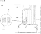
- FIG. 1 is a schematic diagram of an adhesion strength measurement system according to one embodiment of the present invention
- FIG. 2 is a schematic diagram of a fixing jig in the adhesion strength measurement system according to the present invention
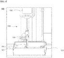
- FIG. 3 is a side view of a fixing jig according to one embodiment of the present invention
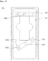
- FIG. 4 is a plan view of a fixing jig according to one embodiment of the present invention.
- an adhesion strength measurement system 100 for wet electrode specimens is configured to include a test substrate 110 to which an electrode specimen 111 is attached, a fixing jig 120 for fixing the test substrate 110, and an adhesion strength measurement unit 130 configured to measure a force at which a mixture layer of the electrode specimen 111 is peeled off by applying a tensile force to one region of the electrode specimen 111.
- the fixing jig 120 may include a recessed portion 121 having a recessed structure to hold the electrolyte solution.
- the adhesion strength measurement system 100 includes the test substrate 110 for fixing the electrode specimen 111.
- the test substrate 110, to which the electrode specimen 111 is attached to fix the electrode specimen 111 may be a metal block or a glass substrate (slide glass), for example, a glass substrate.
- the electrode specimen 111 may be attached to the surface of the test substrate 110 using an adhesive member.
- the mixture layer of the electrode specimen 111 may be attached to the surface of the test substrate 110 and may be attached to regions other than a self-standing region 1111 of the electrode specimen 111.
- the "self-standing region” is a region of the electrode specimen 111 gripped by a grip part 131 of the adhesion strength measurement unit 130, which will be described below, and a space of the electrode specimen 111 that is not impregnated with the electrolyte solution.
- the self-standing region 1111 of the electrode specimen 111 may be gripped by the grip part 131 of the adhesion strength measurement unit 130 to receive a pulling force in a direction perpendicular to the test substrate 110.
- the adhesive member may be a robust adhesive that has a strong adhesion strength and that does not deform during adhesion strength measurement so as not to affect the mixture layer of the electrode specimen 111.
- the present invention is for measuring an adhesion strength to the electrode specimen 111 in a wet state, and the adhesive member may be an adhesive that does not deform and swell when exposed to an electrolyte solution.
- the adhesive member may be an epoxy adhesive or a double-sided tape, for example, a polyimide double-sided tape.
- the adhesion strength measurement system 100 includes the fixing jig 120 for fixing the test substrate 110.
- the fixing jig 120 holds the electrolyte solution therein and fixes the test substrate 110 so that the electrode specimen 111 attached to the test substrate 110 is immersed in the electrolyte solution.
- the recessed portion 121 of a recessed structure to hold the electrolyte solution is included in one surface of the fixing jig 120.
- a space be provided in the fixing jig 120 to accommodate the test substrate 110 to which the electrode specimen 111 to be evaluated is attached.
- the recessed portion 121 may be formed to a predetermined depth to hold the electrolyte solution therein so that the electrode specimen 111 can be easily impregnated with the electrolyte solution.
- the space in which the test substrate 110 is seated may be provided inside the recessed portion 121 of the fixing jig 120.
- the fixing jig 120 includes a fixing part for fixing the test substrate 110.
- the fixing jig 120 may include first and second fixing parts 122 and 123 in the form of a bar.
- the first fixing part 122 may fix one side of the test substrate 110
- the second fixing part 123 may fix the other side of the test substrate 110.
- the first and second fixing parts 122 and 123 are in the form of a bar, and the test substrate 110 fixed to the fixing jig 120 is positioned between an upper surface of the recessed portion 121 and the fixing part 122 and between the upper surface of the recessed portion 121 and the fixing part 123.
- the first and second fixing parts 122 and 123 may further include clamping members 1221 and 1231.
- the clamping members 1221 and 1231 serve to fix the test substrate 110 inserted between the recessed portion 121 of the fixing jig 120 and the first fixing part 122 and between the recessed portion 121 of the fixing jig 120 and the second fixing part 123.
- the clamping members 1221 and 1231 may be clamping bolts.
- first and second fixing parts 122 and 123 may include threaded holes of a structure corresponding to threads formed on the outer circumferential surfaces of the clamping bolts, and the clamping bolts may fix the test substrate 110 while the clamping bolts are engaged with the holes of the first and second fixing parts 122 and 123.
- the first fixing part 122 may be fixed to the inside of the recessed portion 121 of the fixing jig 120 and may be provided on one side of the space where the test substrate 110 is seated.
- the first fixing part 122 may be in the form of a bar, and both ends of the first fixing part 122 in the form of a bar may be fixed to the upper surface of the fixing jig 120.
- the first fixing part 122 may be installed in a direction crossing the direction of the length of the test substrate 110, and the central region other than both ends of the first fixing part 122 may be curved upward so that the test substrate 110 can be positioned between the first fixing part 122 and the upper surface of the fixing jig 120.
- the clamping member 1221 may be installed in the central region of the first fixing part 122, and the clamping member 1221 may fix one side of the test substrate 110.
- the second fixing part 123 may be disposed inside the recessed portion 121 of the fixing jig 120 and provided on the other side of the space where the test substrate 110 is seated.
- the second fixing part 123 may be in the form of a bar like the first fixing part 123, but one side of the second fixing part 123 may be pivotably engaged by a hinge pin (not shown), and the other side of the second fixing part 123 may have a coupling groove 1232 formed thereon.
- the coupling groove 1232 may be coupled to a coupling protrusion, which will be described below.
- One side of the second fixing part 123 is fixed, and the other side, which is pivotable, may easily fix the test substrate 110.
- the fixing jig 120 may include a coupling protrusion 1233 to which a coupling groove 1212 of the second fixing part 123 is to be coupled.
- the coupling protrusion 1233 may be placed in a region opposite to the hinge pin (not shown). That is, when the coupling groove 1232 of the second fixing part 123 is coupled to the coupling protrusion 1233, the first and second fixing parts 122 and 123 may be parallel to each other.
- the central region excluding both ends of the second fixing part 123 may be curved upward so that the test substrate 110 can be positioned between the second fixing part 123 and the upper surface of the fixing jig 120.
- the clamping member 1231 may be installed in the central region of the second fixing part 123.
- the test substrate 110 is disposed in the recessed portion 121 of the fixing jig 120 first.
- the coupling groove 1212 on the other side of the second fixing part 123 is detached from the coupling protrusion 1233.
- the clamping member 1221 of the first fixing part 122 is pressed to fix one side of the test substrate 110.
- the coupling groove 1212 is coupled to the coupling protrusion 1233.
- the clamping member 1231 of the second fixing part 123 is pressed to fix the other side of the test substrate 110. Meanwhile, when the electrode specimen 111 is attached to the test substrate 110, the self-standing region 1111 is excluded.
- the clamping member 1231 of the second fixing part 123 may fix the test substrate 110 except the self-standing region 1111 of the electrode specimen 111.
- the adhesion strength measurement system 100 for wet electrode specimens includes an adhesion strength measurement unit 130.
- the adhesion strength measurement unit 130 may include the grip part 131 for gripping one region of the electrode specimen 111 and measure a force (hereinafter referred to as an adhesion strength) at which the mixture layer of the electrode specimen 111 is peeled off by applying a tensile force to the gripped electrode specimen 111.
- the adhesion strength measurement unit 130 may be a conventional peel tester. As a specific example, the adhesion strength measurement unit 130 may fix the self-standing region 1111 of the electrode specimen 111 to the grip part 131 of the adhesion strength measurement unit 130 in order to measure the adhesion strength of the electrode specimen 111 and measure a force at which the mixture layer is peeled off at an angle of 90°.
- the adhesion strength measurement unit 130 further includes an output unit 133 configured to output the force at which the mixture layer of the electrode specimen 111 is peeled off.
- the output unit 133 may express the adhesion strength of the electrode specimen 111 using a numerical value.
- the adhesion strength measurement unit 130 may further include a storage unit (not shown).
- the storage unit receives and stores the adhesion strength measurement result.
- the storage unit may store the measurement results for the electrode specimen to build a database for the measurement results.
- the type of the electrode specimen 111 is classified according to the type and thickness of the metal thin film, the type of the active material forming the mixture layer, and the like, and accordingly the adhesion strength measurement result for the electrode specimen 111 may be summarized in a table or graph.
- the measurement data is variously combined, it is possible to predict the adhesion strength of the electrode specimen 111, and it is also possible to predict whether an electrode is de-inserted after a battery cell is prepared.
- FIG. 5 is a schematic diagram of an adhesion strength measurement system according to another embodiment of the present invention.
- the adhesion strength measurement unit 130 of the adhesion strength measurement system 100 may include the grip part 131 for gripping the self-standing region, which is one region of the electrode specimen 111.
- the grip part 131 may include a metal jaw face 1311 having a surface where a grid is formed.
- a phenomenon in which the mixture layer of the electrode specimen 111 is de-inserted or the electrode specimen slips while the electrode specimen is pressed by the grip part 131 may occur in the process of measuring the physical properties of the electrode specimen 111.
- the metal jaw face 1311 may be formed of various types of metals, for example, carbon steel, stainless steel, aluminum, or an alloy thereof.
- the metal jaw face 1311 mentioned in the present invention has a surface on which an engraved or embossed grid is formed.
- the grid pattern refers to a pattern in the form of a lattice or a checkerboard grid and collectively refers to forms in which two or more parallel patterns intersect each other.
- the depression depth or protrusion height of the engraved or embossed grid formed on the surface of the metal jaw face 1311 ranges, on average, from 0.001 to 1 mm.
- the depression depth or protrusion height of the grid ranges, on average, from 0.001 to 0.1 mm, from 0.001 to 0.01 mm, from 0.01 to 0.1 mm, or from 0.01 to 0.05 mm.
- the present invention by forming a pattern with a very low level of depression or protrusion, it is possible to increase the fixing force to the grip part 131 without degrading the mechanical properties of the electrode specimen 111.
- the present invention provides an adhesion strength measurement method for wet electrode specimens using the above-described adhesion strength measurement system for wet electrode specimens.
- FIG. 6 is a flowchart illustrating an adhesion strength measurement method for wet electrode specimens in one example of the present invention.
- the adhesion strength measurement method for wet electrode specimens according to the present invention includes operations of attaching an electrode specimen to a test substrate such that a mixture layer of the electrode specimen is in contact with the test substrate (S10); impregnating the test substrate to which the electrode specimen is attached with an electrolyte solution (S20); and measuring the adhesion strength of the electrode specimen by applying a tensile force to the electrode specimen impregnated with the electrolyte solution to measure a force at which the mixture layer of the electrode specimen is peeled off while the test substrate is fixed to a fixing jig (S30).
- the operation of attaching the electrode specimen to the test substrate includes a process of attaching a double-sided adhesive tape to one surface of the test substrate; and a process of attaching the electrode specimen to the test substrate to which the double-sided adhesive tape is attached such that the surface of the mixture layer of the electrode specimen is in contact with the test substrate.
- the process of attaching the electrode specimen may include attaching the electrode specimen except the self-standing region of the electrode specimen to the test substrate.
- the self-standing region which is one region of the electrode specimen, may be gripped by the grip part of the adhesion strength measurement unit and may be a region of the electrode specimen which is not impregnated with an electrolyte solution.
- the operation of attaching the electrode specimen to the test substrate (S10) includes attaching the electrode specimen to be evaluated to a glass substrate, which is the test substrate, using a double-sided adhesive tape.
- the surface of the mixture layer of the electrode specimen may be in contact with the glass substrate.
- it may be rolled with a roller about 10 times.
- the test substrate to which the electrode specimen is attached is left in a temperature range of 40 °C to 80 °C, a temperature range of 50 °C to 70 °C, or a temperature of about 60 °C for 6 to 16 hours, 10 to 14 hours, or about 12 hours, the degree of transfer of the electrode specimen can be confirmed.
- the present invention includes the operation of impregnating the test substrate to which the electrode specimen is attached with the electrolyte solution (S20).
- the operation of impregnating the test substrate to which the electrode specimen is attached with the electrolyte solution (S20) may include a process of impregnating the electrode specimen except the self-standing region with the electrolyte solution.
- the self-standing region is a region gripped by the grip part of the adhesion strength measurement unit and is a region that is not affected by the electrolyte solution during the adhesion strength measurement test.
- the operation of impregnating the test substrate to which the electrode specimen is attached with the electrolyte solution (S20) may include confirming that the electrode specimen is attached to the test substrate, placing the test substrate on a tray, injecting the electrolyte solution, closing the lid of the tray, and then performing impregnation.
- the present invention includes the operation of measuring an adhesion strength using the electrode specimen impregnated with the electrolyte solution (S30).
- the operation of measuring the adhesion strength of the electrode specimen (S30) includes a process of fixing the test substrate to which the electrode specimen is attached to the fixing jig and transferring the electrolyte solution in the tray according to the present invention. Also, by applying a tensile force to the electrode specimen impregnated with the electrolyte while the test substrate is fixed to the fixing jig, a force at which the mixture layer of the electrode specimen is peeled off may be measured.
- the operation of measuring the adhesion strength of the electrode specimen (S30) includes a process of stretching the self-standing region of the electrode specimen in a direction perpendicular to the test substrate. That is, the operation of measuring the adhesion strength of the electrode specimen (S30) may include performing measurement using a 90° peel test.
- the adhesion strength of the electrode specimen may be measured by setting the load of the UTM instrument to zero and then setting the load speed in the range of 10 to 200 mm/min.
- the adhesion strength of the electrode specimen may be measured using the UTM instrument (TA corporation).
- the operation of measuring the adhesion strength of the electrode specimen (S30) includes measuring the adhesion strength of a wet electrode specimen. In this case, the adhesion strength of the electrode can be easily measured while the electrode of the internal state of the secondary battery is simulated.
- the electrode specimen may have a structure having a metal current collector; and an electrode mixture layer formed on one surface or both surfaces of the metal current collector, and the electrode specimen may also have a structure in which a mixture layer including an active material is formed on a positive current collector or a negative current collector.
- the electrolyte solution may include an organic solvent and an electrolyte salt, and the electrolyte salt is a lithium salt.
- the electrolyte salt is a lithium salt.
- Those commonly used in a nonaqueous electrolyte solution for a lithium secondary battery may be used as the lithium salt without limitations.
- the negative ions of the lithium salt may include one or a mixture of two or more selected from the group consisting of F-, Cl-, Br-, I-, NO3-, N(CN)2-, BF 4 -, ClO 4 -, PF 6 -, (CF 3 ) 2 PF 4 -, (CF 3 ) 3 PF 3 -, (CF 3 ) 4 PF 2 -, (CF 3 ) 5 PF-, (CF 3 ) 6 P-, CF 3 SO 3 -, CF 3 CF 2 SO 3 -, (CF 3 SO 2 ) 2 N-, (FSO 2 ) 2 N-, CF 3 CF 2 (CF 3 ) 2 CO-, (CF 3 SO 2 ) 2 CH- , (SF 5 ) 3 C-, CF 3 (CF 2 ) 7 SO 3 -, CF 3 CO 2 -, CH 3 CO 2 -, SCN-, and (CF 3 CF 2 SO 2 ) 2 N-.
- Organic solvents commonly used in electrolyte solution of lithium secondary batteries may be used without limitation as an organic solvent contained in the above-described electrolyte solution.
- ethers, esters, amides, linear carbonates, or cyclic carbonates may be used individually or in a mixture of two or more types.
- the organic solvent may include a cyclic carbonate, a linear carbonate, or a mixture thereof, which is a carbonate compound.
- cyclic carbonate compound examples include one or a mixture of two or more selected from the group consisting of ethylene carbonate (EC), propylene carbonate (PC), 1,2-butylene carbonate, 2,3-butylene carbonate, 1,2-pentylene carbonate, 2,3-pentylene carbonate, vinylene carbonate, vinylethylene carbonate, and halides thereof.
- halides include, but are not limited to, fluoroethylene carbonate (FEC).
- DMC dimethyl carbonate
- DEC diethyl carbonate
- EMC ethylmethyl carbonate
- methylpropyl carbonate methylpropyl carbonate
- ethylpropyl carbonate methylpropyl carbonate
- ethylpropyl carbonate methylpropyl carbonate
- ethylpropyl carbonate methylpropyl carbonate
- ethylpropyl carbonate methylpropyl carbonate
- ethylpropyl carbonate methylpropyl carbonate
- ethylpropyl carbonate methylpropyl carbonate
- ethylpropyl carbonate methylpropyl carbonate
- ethylpropyl carbonate methylpropyl carbonate
- ethylpropyl carbonate methylpropyl carbonate
- ethylpropyl carbonate methylpropyl carbonate
- ethylpropyl carbonate methylpropyl carbonate
- ethylene carbonate and propylene carbonate which are cyclic carbonates
- ethylene carbonate and propylene carbonate are high viscosity organic solvents and have high dielectric constants, and thus the carbonates can better dissociate lithium salts in an electrolyte.
- a low-viscosity and low-dielectric-constant linear carbonate such as dimethyl carbonate or diethyl carbonate are mixed in an appropriate ratio, it is possible to make an electrolyte solution with a higher electrical conductivity.
- one or a mixture of two or more selected from the group consisting of dimethyl ether, diethyl ether, dipropyl ether, methylethyl ether, methylpropyl ether, and ethylpropyl ether may be used as the ether of the organic solvent, but the present invention is not limited thereto.
- one or a mixture of two or more selected from the group consisting of methyl acetate, ethyl acetate, propyl acetate, methyl propionate, ethyl propionate, propyl propionate, ⁇ -butyrolactone, ⁇ -valerolactone, ⁇ -caprolactone, ⁇ -valerolactone, and ⁇ -caprolactone may be used as the ester of the organic solvent, but the present invention is not limited thereto.
- a slot die Using a slot die, one surface of a copper (Cu) thin film, which is a negative current collector, was coated with negative electrode slurries having a solid content of 48% to form a mixture layer on the surface of the copper thin film. Then, the mixture layer was rolled by a roll pressing method to prepare an electrode in which the mixture layer was formed. At this time, when the coating was performed with the negative electrode slurries, the coating speed was 32 m/min, and the rolling pressure was 1.05 tons/cm 2 . Then, the electrode was punched to a size of 20 mm x 125 mm to prepare an electrode specimen.
- Cu copper
- An electrode specimen was prepared in the same manner as in Preparation Example 1, except that the coating speed of the negative electrode slurries, the solid content, and the pressure during the rolling process were changed.
- the adhesion strength to an electrode specimen prepared in each Preparation Example was measured by a 90° peel test.
- an imide double-sided tape was attached to the slide glass, and the electrode prepared in each Preparation Example was placed and adhered thereto by rolling a roller with a load of 2 kg ten times. Meanwhile, the electrode specimen was attached to one surface of the slide glass so that the mixture layer of the electrode specimen was in contact with the surface of the slide glass.
- the slide glass to which the electrode specimen was attached was left in an oven at 60 °C for about 12 hours, and the degree of adhesion strength of the electrode specimen to the double-sided tape was checked using a torn portion of the electrode specimen.
- the adhesion strength of the electrode specimen was measured using the 90° peel test.
- an imide double-sided tape was attached to the slide glass, and the electrode prepared in each Preparation Example was placed and adhered thereto by rolling a roller with a load of 2 kg ten times.
- the electrode specimen except the self-standing region of the electrode specimen was attached to the slide glass so that the mixture layer of the electrode specimen was in contact with the surface of the slide glass.
- the slide glass to which the electrode specimen was attached was left in an oven at 60° C for about 12 hours, and the degree of adhesion strength of the electrode specimen to the double-sided tape was checked using a torn portion of the electrode specimen.
- the lithium secondary battery prepared as described above was charged and discharged 50 times at 25 °C, and the cross-section of the negative electrode was observed after disassembly. Also, the results of whether the active material was de-inserted are shown in Table 2 below. [Table 2] No.
Landscapes
- Chemical & Material Sciences (AREA)
- Immunology (AREA)
- Pathology (AREA)
- Health & Medical Sciences (AREA)
- Analytical Chemistry (AREA)
- Biochemistry (AREA)
- General Health & Medical Sciences (AREA)
- General Physics & Mathematics (AREA)
- Physics & Mathematics (AREA)
- Life Sciences & Earth Sciences (AREA)
- Manufacturing & Machinery (AREA)
- Engineering & Computer Science (AREA)
- Chemical Kinetics & Catalysis (AREA)
- Electrochemistry (AREA)
- General Chemical & Material Sciences (AREA)
- Investigating Strength Of Materials By Application Of Mechanical Stress (AREA)
- Battery Electrode And Active Subsutance (AREA)
- Testing Resistance To Weather, Investigating Materials By Mechanical Methods (AREA)
- Investigating Or Analyzing Materials By The Use Of Electric Means (AREA)
Abstract
Description
- This application claims the benefit of priority based on
Korean Patent Application No. 10-2021-0037134, filed on March 23, 2021 - The present invention relates to an adhesion strength measurement system for wet electrode specimens and an adhesion strength measurement method for wet electrode specimens using the same.
- With developments in technology and increases in demand for mobile devices, the demand for secondary batteries as an energy source is rapidly increasing. Among secondary batteries, lithium secondary batteries are widely used as an energy source for various electronic products as well as various mobile devices because they have high energy density and operating voltage and excellent preservation and life cycle characteristics.
- Also, secondary batteries are attracting attention as an energy source for electric vehicles or hybrid electric vehicles, which have been proposed as a solution to air pollution caused by conventional gasoline and diesel vehicles which use fossil fuels and the like. In order to apply secondary batteries as an energy source for electric vehicles, the secondary batteries need to be high-output secondary batteries.
- These secondary batteries are being developed as models that can realize high voltage and high capacity according to consumers' needs. In order to implement high capacity, an optimization process for a cathode material, an anode material, a separator, and an electrolyte solution, which are the four major elements of a secondary battery, is required in a limited space.
- Meanwhile, an electrode to be applied to a secondary battery is prepared by applying an electrode slurry on a current collector and drying in the form of a thin metal thin film. Because a mechanical/environmental load is applied to an electrode in the electrode preparation process, it is required to sample an electrode specimen after the process of a specific step or for each part and to evaluate the physical properties of the specimen.
- The adhesion strength of the electrode during the evaluation of the physical properties of the electrode is a major factor that affects the preparation processability of the secondary battery or the performance of the secondary battery. Thus, a process of measuring the adhesion strength of an electrode mixture layer (hereinafter referred to as the adhesion strength of the electrode) during the adhesive coating of the electrode current collector with the electrode slurries is required during the preparation process. Specifically, a method of measuring the adhesion strength of an electrode uses an apparatus for measuring peel strength by peeling the electrode mixture layer (active material) from the electrode current collector in order to measure the adhesion strength of the electrode mixture layer.
- As described above, in a typical electrode adhesion strength measurement method, the peel strength is measured using a dried electrode.
- However, an electrode in an actual secondary battery is impregnated with an electrolyte solution. Therefore, in order to more accurately evaluate the preparation processability of a secondary battery or the performance of a secondary battery, there is a need for a technology capable of simulating the actual state of an electrode inside the secondary battery and measuring the adhesion strength of the electrode.
- The present invention is to solve the above problems and provides an adhesion strength measurement system for wet electrode specimens, the system being capable of evaluating the adhesion strength of an electrode specimen impregnated with an electrolyte solution, and an adhesion strength measurement method for wet electrode specimens using the same.
- The present invention provides an adhesion strength measurement system for wet electrode specimens. In one example, the adhesion strength measurement system for wet electrode specimens according to the present invention includes a test substrate to which an electrode specimen is attached; a fixing jig configured to fix the test substrate so that the electrode specimen attached to the test substrate is immersed in an electrolyte solution; and an adhesion strength measurement unit configured to measure a force at which a mixture layer of the electrode specimen is peeled off by applying a tensile force to the gripped electrode specimen, the adhesion strength measurement unit including a grip part configured to grip one region of the electrode specimen.
- Specifically, the adhesion strength measurement system includes a test substrate to which a surface of a mixture layer of an electrode specimen is attached; a fixing jig configured to hold an electrolyte solution therein and configured to fix the test substrate such that the electrode specimen attached to the test substrate is immersed in the electrolyte solution, and an adhesion strength measurement unit configured to measure a force at which the mixture layer of the electrode specimen is peeled off by applying a tensile force to the gripped electrode specimen, the adhesion strength measurement unit including a grip part configured to grip one region of the electrode specimen. In this case, the fixing jig may have one surface in which a recessed portion of a structure recessed to hold the electrolyte solution is formed.
- Furthermore, the present invention provides an adhesion strength measurement method using the above-described adhesion strength measurement system for wet electrode specimens.
- In one example, the adhesion strength measurement method for wet electrode specimens according to the present invention includes operations of impregnating a test substrate to which an electrode specimen is attached with an electrolyte solution and measuring the adhesion strength of the electrode specimen by applying a tensile force to the electrode specimen impregnated with the electrolyte solution while the test substrate is fixed to a fixing jig.
- Specifically, the adhesion strength measurement method includes operations of attaching an electrode specimen to a test substrate such that a mixture layer of the electrode specimen is in contact with the test substrate; impregnating the test substrate to which the electrode specimen is attached with an electrolyte solution; and measuring the adhesion strength of the electrode specimen by applying a tensile force to the electrode specimen impregnated with the electrolyte solution to measure a force at which the mixture layer of the electrode specimen is peeled off while the test substrate is fixed to a fixing jig.
- With the adhesion strength measurement system for wet electrode specimens and the adhesion strength measurement method for wet electrode specimens using the same according to the present invention, it is possible to simulate an electrode in a secondary battery, thereby facilitating the measurement of the adhesion strength of the electrode.
-
-
FIG. 1 is a schematic diagram of an adhesion strength measurement system according to one embodiment of the present invention. -
FIG. 2 is a schematic diagram of a fixing jig in the adhesion strength measurement system according to the present invention. -
FIG. 3 is a side view of a fixing jig according to one embodiment of the present invention. -
FIG. 4 is a plan view of a fixing jig according to one embodiment of the present invention. -
FIG. 5 is a schematic diagram of an adhesion strength measurement system according to another embodiment of the present invention. -
FIG. 6 is a flowchart illustrating an adhesion strength measurement method for wet electrode specimens in one example of the present invention. - The present invention provides an adhesion strength measurement system for wet electrode specimens. In one example, the adhesion strength measurement system for wet electrode specimens according to the present invention includes a test substrate to which an electrode specimen is attached; a fixing jig configured to fix the test substrate so that the electrode specimen attached to the test substrate is immersed in an electrolyte solution; and an adhesion strength measurement unit configured to measure a force at which a mixture layer of the electrode specimen is peeled off by applying a tensile force to the gripped electrode specimen, the adhesion strength measurement unit including a grip part configured to grip one region of the electrode specimen.
- An electrode in a secondary battery is impregnated with an electrolyte solution. The adhesion strength of an electrode may vary depending on whether the electrode is wet or dry. According to the present invention, it is possible to simulate the state of an electrode positioned in a secondary battery and then measure the adhesion strength of the electrode.
- In one embodiment, the electrode specimen is attached to the test substrate such that the surface of the mixture layer of the electrode specimen is in contact with the test substrate, and the fixing jig holds an electrolyte solution therein and fixes the test substrate such that the electrode specimen attached to the test substrate is immersed in the electrolyte solution.
- In a specific embodiment, the fixing jig has one surface in which a recessed portion of a structure recessed to hold the electrolyte solution is formed. The electrolyte solution is held in the recessed portion.
- In one example, the fixing jig includes first and second fixing parts configured in the form of a bar to fix one side and the other side of the test substrate, respectively. Meanwhile, one side of the second fixing part may be pivotably engaged by a hinge pin, and the other side of the second fixing part may have a coupling groove formed thereon.
- In a specific example, the fixing jig includes a coupling protrusion to which the coupling groove of the second fixing part is to be coupled. In addition, the coupling protrusion may be positioned in a region facing the hinge pin.
- Furthermore, the first and second fixing parts may include clamping members for pressing the test substrate.
- In another example, the grip part of the adhesion strength measurement unit includes a metal jaw face having a surface in which an engraved or embossed grid is formed. In a specific example, the depression depth or protrusion height of the engraved or embossed grid formed on the surface of the metal jaw face may range, on average, from 0.001 to 1 mm.
- In still another example, the adhesion strength measurement unit according to the present invention further includes an output unit configured to output the force at which the mixture layer of the electrode specimen is peeled off.
- Furthermore, the present invention provides an adhesion strength measurement method using the above-described adhesion strength measurement system for wet electrode specimens.
- In one example, the adhesion strength measurement method for wet electrode specimens according to the present invention includes operations of impregnating a test substrate to which an electrode specimen is attached with the electrolyte solution and measuring the adhesion strength of the electrode specimen by applying a tensile force to the electrode specimen impregnated with the electrolyte solution while the test substrate is fixed to a fixing jig.
- In a specific example, the operation of attaching the electrode specimen to the test substrate includes attaching the electrode specimen to the test substrate such that the mixture layer of the electrode specimen is in contact with the test substrate. Also, the operation of measuring the adhesion strength of the electrode specimen includes measuring the force at which the mixture layer of the electrode specimen is peeled off by applying a tensile force to the electrode specimen impregnated with the electrolyte solution.
- Specifically, the adhesion strength measurement method for wet electrode specimens according to the present invention includes operations of attaching an electrode specimen to a test substrate such that the mixture layer of the electrode specimen is in contact with the test substrate; impregnating the test substrate to which the electrode specimen is attached with the electrolyte solution; and measuring the adhesion strength of the electrode specimen by applying a tensile force to the electrode specimen impregnated with the electrolyte solution to measure the force at which the mixture layer of the electrode specimen is peeled off while the test substrate is fixed to a fixing jig.
- In one example, the operation of attaching the electrode specimen to the test substrate includes a process of attaching a double-sided adhesive tape to one surface of the test substrate; and a process of attaching the electrode specimen to the test substrate to which the double-sided adhesive tape is attached such that the surface of the mixture layer of the electrode specimen is in contact with the test substrate. In this case, the process of attaching the electrode specimen may include attaching the electrode specimen except the self-standing region of the electrode specimen to the test substrate.
- In one example, the operation of impregnating the test substrate to which the electrode specimen is attached with the electrolyte solution may include a process of impregnating the electrode specimen except the self-standing region with the electrolyte solution.
- In another example, the operation of measuring the adhesion strength of the electrode specimen includes a process of stretching the self-standing region of the electrode specimen in a direction perpendicular to the test substrate.
- Meanwhile, the electrode specimen may have a structure with a metal current collector and an electrode mixture layer formed on one or both sides of the metal current collector.
- The present invention will be described in detail below. Prior to the description, the terms or words used in the present specification and claims should not be construed as being limited to conventional or dictionary meanings and should be interpreted with meanings and concepts consistent with the technical spirit of the present invention, based on the principle that the inventor can appropriately define the concepts of the terms in order to best describe his invention.
- The present invention relates to an adhesion strength measurement system for wet electrode specimens and an adhesion strength measurement method for wet electrode specimens using the same.
- Generally, the adhesion strength measurement method for an electrode includes peeling an electrode mixture layer from an electrode current collector and measuring peeling strength in order to measure the adhesion strength of the electrode mixture layer. Specifically, a double-sided tape is attached to a slide glass, and an electrode specimen is attached to one side of the slide glass such that the mixture layer of the electrode specimen to be evaluated is in contact with the slide glass surface. Also, a force at which one side of the electrode specimen was pulled and peeled from the slide glass was measured using a UTM instrument. That is, in the related art, in order to measure the adhesion strength of an electrode, the peel strength of a dried electrode was measured.
- However, actually, an electrode in a secondary battery is impregnated with an electrolyte solution. Therefore, in order to more accurately evaluate the preparation processability of a secondary battery or the performance of a secondary battery, there is a need for a technology capable of simulating the actual state of an electrode inside the secondary battery and measuring the adhesion strength of the electrode.
- Therefore, the present invention provides an adhesion strength measurement system for wet electrode specimens, the system being capable of evaluating the adhesion strength of an electrode specimen impregnated with an electrolyte solution, and an adhesion strength measurement for a wet electrode specimen using the same.
- In the present invention, the term "electrode specimen" refers to an object to be measured using an adhesion strength measurement system for wet electrode specimens according to the present invention and may be an electrode having a metal current collector and an electrode mixture layer formed on one or both sides of the metal current collector. For example, the electrode specimen may be a specimen obtained by punching an electrode to a predetermined width and a predetermined length.
- An adhesion strength measurement system for wet electrode specimens and an adhesion strength measurement method for wet electrode specimens using the same according to the present invention will be described in detail with reference to the accompanying drawings.
-
FIG. 1 is a schematic diagram of an adhesion strength measurement system according to one embodiment of the present invention,FIG. 2 is a schematic diagram of a fixing jig in the adhesion strength measurement system according to the present invention,FIG. 3 is a side view of a fixing jig according to one embodiment of the present invention, andFIG. 4 is a plan view of a fixing jig according to one embodiment of the present invention. - Referring to
FIGS. 1 and2 , an adhesionstrength measurement system 100 for wet electrode specimens according to the present invention is configured to include atest substrate 110 to which anelectrode specimen 111 is attached, a fixingjig 120 for fixing thetest substrate 110, and an adhesionstrength measurement unit 130 configured to measure a force at which a mixture layer of theelectrode specimen 111 is peeled off by applying a tensile force to one region of theelectrode specimen 111. Meanwhile, the fixingjig 120 may include a recessedportion 121 having a recessed structure to hold the electrolyte solution. - As one example, the adhesion
strength measurement system 100 according to the present invention includes thetest substrate 110 for fixing theelectrode specimen 111. Thetest substrate 110, to which theelectrode specimen 111 is attached to fix theelectrode specimen 111, may be a metal block or a glass substrate (slide glass), for example, a glass substrate. - Meanwhile, the
electrode specimen 111 may be attached to the surface of thetest substrate 110 using an adhesive member. As a specific example, the mixture layer of theelectrode specimen 111 may be attached to the surface of thetest substrate 110 and may be attached to regions other than a self-standingregion 1111 of theelectrode specimen 111. Here, the "self-standing region" is a region of theelectrode specimen 111 gripped by agrip part 131 of the adhesionstrength measurement unit 130, which will be described below, and a space of theelectrode specimen 111 that is not impregnated with the electrolyte solution. The self-standingregion 1111 of theelectrode specimen 111 may be gripped by thegrip part 131 of the adhesionstrength measurement unit 130 to receive a pulling force in a direction perpendicular to thetest substrate 110. - The adhesive member may be a robust adhesive that has a strong adhesion strength and that does not deform during adhesion strength measurement so as not to affect the mixture layer of the
electrode specimen 111. In addition, the present invention is for measuring an adhesion strength to theelectrode specimen 111 in a wet state, and the adhesive member may be an adhesive that does not deform and swell when exposed to an electrolyte solution. The adhesive member may be an epoxy adhesive or a double-sided tape, for example, a polyimide double-sided tape. - In one example, the adhesion
strength measurement system 100 according to the present invention includes the fixingjig 120 for fixing thetest substrate 110. In a specific example, the fixingjig 120 holds the electrolyte solution therein and fixes thetest substrate 110 so that theelectrode specimen 111 attached to thetest substrate 110 is immersed in the electrolyte solution. In particular, the recessedportion 121 of a recessed structure to hold the electrolyte solution is included in one surface of the fixingjig 120. - Specifically, it is preferable that a space be provided in the fixing
jig 120 to accommodate thetest substrate 110 to which theelectrode specimen 111 to be evaluated is attached. In addition, the recessedportion 121 may be formed to a predetermined depth to hold the electrolyte solution therein so that theelectrode specimen 111 can be easily impregnated with the electrolyte solution. Meanwhile, the space in which thetest substrate 110 is seated may be provided inside the recessedportion 121 of the fixingjig 120. - In addition, the fixing
jig 120 includes a fixing part for fixing thetest substrate 110. In a specific example, the fixingjig 120 may include first and second fixingparts first fixing part 122 may fix one side of thetest substrate 110, and thesecond fixing part 123 may fix the other side of thetest substrate 110. - The first and second fixing
parts test substrate 110 fixed to the fixingjig 120 is positioned between an upper surface of the recessedportion 121 and the fixingpart 122 and between the upper surface of the recessedportion 121 and the fixingpart 123. Also, the first and second fixingparts members members test substrate 110 inserted between the recessedportion 121 of the fixingjig 120 and the first fixingpart 122 and between the recessedportion 121 of the fixingjig 120 and thesecond fixing part 123. For example, the clampingmembers parts test substrate 110 while the clamping bolts are engaged with the holes of the first and second fixingparts - As shown in
FIG. 3 , the first fixingpart 122 may be fixed to the inside of the recessedportion 121 of the fixingjig 120 and may be provided on one side of the space where thetest substrate 110 is seated. As described above, the first fixingpart 122 may be in the form of a bar, and both ends of the first fixingpart 122 in the form of a bar may be fixed to the upper surface of the fixingjig 120. Meanwhile, the first fixingpart 122 may be installed in a direction crossing the direction of the length of thetest substrate 110, and the central region other than both ends of the first fixingpart 122 may be curved upward so that thetest substrate 110 can be positioned between the first fixingpart 122 and the upper surface of the fixingjig 120. Furthermore, the clampingmember 1221 may be installed in the central region of the first fixingpart 122, and the clampingmember 1221 may fix one side of thetest substrate 110. - As shown in
FIG. 4 , thesecond fixing part 123 may be disposed inside the recessedportion 121 of the fixingjig 120 and provided on the other side of the space where thetest substrate 110 is seated. However, thesecond fixing part 123 may be in the form of a bar like the first fixingpart 123, but one side of thesecond fixing part 123 may be pivotably engaged by a hinge pin (not shown), and the other side of thesecond fixing part 123 may have acoupling groove 1232 formed thereon. For reference, thecoupling groove 1232 may be coupled to a coupling protrusion, which will be described below. One side of thesecond fixing part 123 is fixed, and the other side, which is pivotable, may easily fix thetest substrate 110. - Furthermore, the fixing
jig 120 may include acoupling protrusion 1233 to which acoupling groove 1212 of thesecond fixing part 123 is to be coupled. In a specific example, thecoupling protrusion 1233 may be placed in a region opposite to the hinge pin (not shown). That is, when thecoupling groove 1232 of thesecond fixing part 123 is coupled to thecoupling protrusion 1233, the first and second fixingparts - Meanwhile, like the first fixing part, the central region excluding both ends of the
second fixing part 123 may be curved upward so that thetest substrate 110 can be positioned between thesecond fixing part 123 and the upper surface of the fixingjig 120. Also, the clampingmember 1231 may be installed in the central region of thesecond fixing part 123. - In order to fix the
test substrate 110 to which theelectrode specimen 111 is attached to the fixingjig 120, thetest substrate 110 is disposed in the recessedportion 121 of the fixingjig 120 first. In this case, thecoupling groove 1212 on the other side of thesecond fixing part 123 is detached from thecoupling protrusion 1233. Also, the clampingmember 1221 of the first fixingpart 122 is pressed to fix one side of thetest substrate 110. - Subsequently, by pivoting the other side of the
second fixing part 123, thecoupling groove 1212 is coupled to thecoupling protrusion 1233. Also, the clampingmember 1231 of thesecond fixing part 123 is pressed to fix the other side of thetest substrate 110. Meanwhile, when theelectrode specimen 111 is attached to thetest substrate 110, the self-standingregion 1111 is excluded. The clampingmember 1231 of thesecond fixing part 123 may fix thetest substrate 110 except the self-standingregion 1111 of theelectrode specimen 111. - In one example, the adhesion
strength measurement system 100 for wet electrode specimens according to the present invention includes an adhesionstrength measurement unit 130. In a specific example, the adhesionstrength measurement unit 130 may include thegrip part 131 for gripping one region of theelectrode specimen 111 and measure a force (hereinafter referred to as an adhesion strength) at which the mixture layer of theelectrode specimen 111 is peeled off by applying a tensile force to the grippedelectrode specimen 111. - The adhesion
strength measurement unit 130 may be a conventional peel tester. As a specific example, the adhesionstrength measurement unit 130 may fix the self-standingregion 1111 of theelectrode specimen 111 to thegrip part 131 of the adhesionstrength measurement unit 130 in order to measure the adhesion strength of theelectrode specimen 111 and measure a force at which the mixture layer is peeled off at an angle of 90°. - In one example, the adhesion
strength measurement unit 130 further includes an output unit 133 configured to output the force at which the mixture layer of theelectrode specimen 111 is peeled off. The output unit 133 may express the adhesion strength of theelectrode specimen 111 using a numerical value. - As another example, the adhesion
strength measurement unit 130 may further include a storage unit (not shown). When the measurement of the adhesion strength of theelectrode specimen 111 is finished, the storage unit receives and stores the adhesion strength measurement result. The storage unit may store the measurement results for the electrode specimen to build a database for the measurement results. Specifically, the type of theelectrode specimen 111 is classified according to the type and thickness of the metal thin film, the type of the active material forming the mixture layer, and the like, and accordingly the adhesion strength measurement result for theelectrode specimen 111 may be summarized in a table or graph. When the measurement data is variously combined, it is possible to predict the adhesion strength of theelectrode specimen 111, and it is also possible to predict whether an electrode is de-inserted after a battery cell is prepared. -
FIG. 5 is a schematic diagram of an adhesion strength measurement system according to another embodiment of the present invention. Referring toFIG. 5 , the adhesionstrength measurement unit 130 of the adhesionstrength measurement system 100 may include thegrip part 131 for gripping the self-standing region, which is one region of theelectrode specimen 111. - In this case, the
grip part 131 may include ametal jaw face 1311 having a surface where a grid is formed. A phenomenon in which the mixture layer of theelectrode specimen 111 is de-inserted or the electrode specimen slips while the electrode specimen is pressed by thegrip part 131 may occur in the process of measuring the physical properties of theelectrode specimen 111. According to the present invention, by forming a grid on a surface of the jaw face facing theelectrode specimen 111, it is possible to increase the fixing force of thegrip part 131 to theelectrode specimen 111. Themetal jaw face 1311 may be formed of various types of metals, for example, carbon steel, stainless steel, aluminum, or an alloy thereof. - In one example, the
metal jaw face 1311 mentioned in the present invention has a surface on which an engraved or embossed grid is formed. By forming the grid pattern on the surface of themetal jaw face 1311, it is possible to increase the fixing force to theelectrode specimen 111. In the present invention, the term "grid" refers to a pattern in the form of a lattice or a checkerboard grid and collectively refers to forms in which two or more parallel patterns intersect each other. In a specific example, the depression depth or protrusion height of the engraved or embossed grid formed on the surface of themetal jaw face 1311 ranges, on average, from 0.001 to 1 mm. For example, the depression depth or protrusion height of the grid ranges, on average, from 0.001 to 0.1 mm, from 0.001 to 0.01 mm, from 0.01 to 0.1 mm, or from 0.01 to 0.05 mm. According to the present invention, by forming a pattern with a very low level of depression or protrusion, it is possible to increase the fixing force to thegrip part 131 without degrading the mechanical properties of theelectrode specimen 111. - In addition, the present invention provides an adhesion strength measurement method for wet electrode specimens using the above-described adhesion strength measurement system for wet electrode specimens.
-
FIG. 6 is a flowchart illustrating an adhesion strength measurement method for wet electrode specimens in one example of the present invention. Referring toFIG. 6 , the adhesion strength measurement method for wet electrode specimens according to the present invention includes operations of attaching an electrode specimen to a test substrate such that a mixture layer of the electrode specimen is in contact with the test substrate (S10); impregnating the test substrate to which the electrode specimen is attached with an electrolyte solution (S20); and measuring the adhesion strength of the electrode specimen by applying a tensile force to the electrode specimen impregnated with the electrolyte solution to measure a force at which the mixture layer of the electrode specimen is peeled off while the test substrate is fixed to a fixing jig (S30). - First, the operation of attaching the electrode specimen to the test substrate (S10) includes a process of attaching a double-sided adhesive tape to one surface of the test substrate; and a process of attaching the electrode specimen to the test substrate to which the double-sided adhesive tape is attached such that the surface of the mixture layer of the electrode specimen is in contact with the test substrate. In this case, the process of attaching the electrode specimen may include attaching the electrode specimen except the self-standing region of the electrode specimen to the test substrate. The self-standing region, which is one region of the electrode specimen, may be gripped by the grip part of the adhesion strength measurement unit and may be a region of the electrode specimen which is not impregnated with an electrolyte solution.
- As a specific example, the operation of attaching the electrode specimen to the test substrate (S10) includes attaching the electrode specimen to be evaluated to a glass substrate, which is the test substrate, using a double-sided adhesive tape. In this case, the surface of the mixture layer of the electrode specimen may be in contact with the glass substrate. In addition, after attaching the electrode specimen to the glass substrate, it may be rolled with a roller about 10 times. Also, after the test substrate to which the electrode specimen is attached is left in a temperature range of 40 °C to 80 °C, a temperature range of 50 °C to 70 °C, or a temperature of about 60 °C for 6 to 16 hours, 10 to 14 hours, or about 12 hours, the degree of transfer of the electrode specimen can be confirmed.
- Next, the present invention includes the operation of impregnating the test substrate to which the electrode specimen is attached with the electrolyte solution (S20). In this case, the operation of impregnating the test substrate to which the electrode specimen is attached with the electrolyte solution (S20) may include a process of impregnating the electrode specimen except the self-standing region with the electrolyte solution. The self-standing region is a region gripped by the grip part of the adhesion strength measurement unit and is a region that is not affected by the electrolyte solution during the adhesion strength measurement test. In a specific example, the operation of impregnating the test substrate to which the electrode specimen is attached with the electrolyte solution (S20) may include confirming that the electrode specimen is attached to the test substrate, placing the test substrate on a tray, injecting the electrolyte solution, closing the lid of the tray, and then performing impregnation.
- Also, the present invention includes the operation of measuring an adhesion strength using the electrode specimen impregnated with the electrolyte solution (S30). The operation of measuring the adhesion strength of the electrode specimen (S30) includes a process of fixing the test substrate to which the electrode specimen is attached to the fixing jig and transferring the electrolyte solution in the tray according to the present invention. Also, by applying a tensile force to the electrode specimen impregnated with the electrolyte while the test substrate is fixed to the fixing jig, a force at which the mixture layer of the electrode specimen is peeled off may be measured.
- In a specific example, the operation of measuring the adhesion strength of the electrode specimen (S30) includes a process of stretching the self-standing region of the electrode specimen in a direction perpendicular to the test substrate. That is, the operation of measuring the adhesion strength of the electrode specimen (S30) may include performing measurement using a 90° peel test. For example, the adhesion strength of the electrode specimen may be measured by setting the load of the UTM instrument to zero and then setting the load speed in the range of 10 to 200 mm/min. For example, the adhesion strength of the electrode specimen may be measured using the UTM instrument (TA corporation).
- The operation of measuring the adhesion strength of the electrode specimen (S30) includes measuring the adhesion strength of a wet electrode specimen. In this case, the adhesion strength of the electrode can be easily measured while the electrode of the internal state of the secondary battery is simulated.
- Meanwhile, the electrode specimen may have a structure having a metal current collector; and an electrode mixture layer formed on one surface or both surfaces of the metal current collector, and the electrode specimen may also have a structure in which a mixture layer including an active material is formed on a positive current collector or a negative current collector.
- Furthermore, the electrolyte solution may include an organic solvent and an electrolyte salt, and the electrolyte salt is a lithium salt. Those commonly used in a nonaqueous electrolyte solution for a lithium secondary battery may be used as the lithium salt without limitations. For example, the negative ions of the lithium salt may include one or a mixture of two or more selected from the group consisting of F-, Cl-, Br-, I-, NO3-, N(CN)2-, BF4-, ClO4-, PF6-, (CF3)2PF4-, (CF3)3PF3-, (CF3)4PF2-, (CF3)5PF-, (CF3)6P-, CF3SO3-, CF3CF2SO3-, (CF3SO2)2N-, (FSO2)2N-, CF3CF2(CF3)2CO-, (CF3SO2)2CH- , (SF5)3C-, CF3(CF2)7SO3-, CF3CO2-, CH3CO2-, SCN-, and (CF3CF2SO2)2N-.
- Organic solvents commonly used in electrolyte solution of lithium secondary batteries may be used without limitation as an organic solvent contained in the above-described electrolyte solution. For example, ethers, esters, amides, linear carbonates, or cyclic carbonates may be used individually or in a mixture of two or more types. Typically, the organic solvent may include a cyclic carbonate, a linear carbonate, or a mixture thereof, which is a carbonate compound.
- Specific examples of the cyclic carbonate compound include one or a mixture of two or more selected from the group consisting of ethylene carbonate (EC), propylene carbonate (PC), 1,2-butylene carbonate, 2,3-butylene carbonate, 1,2-pentylene carbonate, 2,3-pentylene carbonate, vinylene carbonate, vinylethylene carbonate, and halides thereof.
- Examples of these halides include, but are not limited to, fluoroethylene carbonate (FEC).
- Also, one or a mixture of two or more selected from the group consisting of dimethyl carbonate (DMC), diethyl carbonate (DEC), dipropyl carbonate, ethylmethyl carbonate (EMC), methylpropyl carbonate, and ethylpropyl carbonate may be typically used as specific examples of the linear carbonate compound, but the present invention is not limited thereto.
- In particular, among the carbonate-based organic solvents, ethylene carbonate and propylene carbonate, which are cyclic carbonates, are high viscosity organic solvents and have high dielectric constants, and thus the carbonates can better dissociate lithium salts in an electrolyte. When the cyclic carbonate and a low-viscosity and low-dielectric-constant linear carbonate such as dimethyl carbonate or diethyl carbonate are mixed in an appropriate ratio, it is possible to make an electrolyte solution with a higher electrical conductivity.
- Also, one or a mixture of two or more selected from the group consisting of dimethyl ether, diethyl ether, dipropyl ether, methylethyl ether, methylpropyl ether, and ethylpropyl ether may be used as the ether of the organic solvent, but the present invention is not limited thereto.
- Also, one or a mixture of two or more selected from the group consisting of methyl acetate, ethyl acetate, propyl acetate, methyl propionate, ethyl propionate, propyl propionate, γ-butyrolactone, γ-valerolactone, γ-caprolactone, α-valerolactone, and ε-caprolactone may be used as the ester of the organic solvent, but the present invention is not limited thereto.
- Hereinafter, the present invention will be described in detail with reference to embodiments, etc. However, the configurations described in the embodiments described herein are only examples of the present invention and do not represent all the technical spirit of the present invention, so it should be understood that various equivalents and modifications may be substituted for the configurations at the time of filing the present application.
- Using a slot die, one surface of a copper (Cu) thin film, which is a negative current collector, was coated with negative electrode slurries having a solid content of 48% to form a mixture layer on the surface of the copper thin film. Then, the mixture layer was rolled by a roll pressing method to prepare an electrode in which the mixture layer was formed. At this time, when the coating was performed with the negative electrode slurries, the coating speed was 32 m/min, and the rolling pressure was 1.05 tons/cm2. Then, the electrode was punched to a size of 20 mm x 125 mm to prepare an electrode specimen.
- An electrode specimen was prepared in the same manner as in Preparation Example 1, except that the coating speed of the negative electrode slurries, the solid content, and the pressure during the rolling process were changed.
- In each preparation example, the coating speed of the negative electrode slurries, the solid content, and the rolling pressure of the mixture layer during the preparation of the electrode were as shown in Table 1 below.
[Table 1] No. Coating speed (m/min) Solid content (%) Rolling nip pressure (tons/cm2) Preparation Example 1 32 48 1.05 Preparation Example 2 50 48 1.02 Preparation Example 3 50 48 1.00 Preparation Example 4 50 48 0.86 Preparation Example 5 50 48 1.05 Preparation Example 6 50 49 0.99 - The adhesion strength to an electrode specimen prepared in each Preparation Example was measured by a 90° peel test.
- Specifically, an imide double-sided tape was attached to the slide glass, and the electrode prepared in each Preparation Example was placed and adhered thereto by rolling a roller with a load of 2 kg ten times. Meanwhile, the electrode specimen was attached to one surface of the slide glass so that the mixture layer of the electrode specimen was in contact with the surface of the slide glass.
- Then, the slide glass to which the electrode specimen was attached was left in an oven at 60 °C for about 12 hours, and the degree of adhesion strength of the electrode specimen to the double-sided tape was checked using a torn portion of the electrode specimen.
- Next, a force at which one side of the electrode specimen was pulled at 100 mm/min and peeled off from the slide glass was measured using the UTM instrument (TA corporation). At this time, the measurement angle between the slide glass and the electrode was 90°.
- At this time, three electrode specimens were prepared, the adhesion strength of each electrode specimen was measured through the above-described 90° peel test, and the average value was found. The results are shown in Table 2 below.
- After the electrode specimen prepared in each Preparation Example was impregnated with an electrolyte solution, the adhesion strength of the electrode specimen was measured using the 90° peel test.
- Specifically, an imide double-sided tape was attached to the slide glass, and the electrode prepared in each Preparation Example was placed and adhered thereto by rolling a roller with a load of 2 kg ten times. In this case, the electrode specimen except the self-standing region of the electrode specimen was attached to the slide glass so that the mixture layer of the electrode specimen was in contact with the surface of the slide glass.
- Then, the slide glass to which the electrode specimen was attached was left in an oven at 60° C for about 12 hours, and the degree of adhesion strength of the electrode specimen to the double-sided tape was checked using a torn portion of the electrode specimen.
- Next, the slide glass to which the electrode specimen was attached was placed on a tray, and an electrolyte solution in which 1 M LiPF6 was dissolved in a mixed solvent (DEC:EC=1:1) of dimethyl carbonate (DEC) and ethylene carbonate (EC) was placed so that the electrode specimen was impregnated with the electrolyte solution. In this case, the self-standing region of the electrode specimen was not impregnated with the electrolyte solution. Also, the electrolyte solution and the electrode specimen were transferred to an adhesion strength measurement jig of the present invention, and the adhesion strength of the electrode specimen was measured in the same manner as in Experimental Example 1. At this time, three electrode specimens were prepared, the adhesion strength of each electrode specimen was measured through the above-described 90° peel test, and the average value was found. The results are shown in Table 2 below.
- After a monocell was prepared using a negative electrode according to each preparation example, it was checked whether a negative-electrode active material fell out.
- In the monocell, lithium metal was used as a positive electrode, and a separator was interposed between the negative electrode and the positive electrode. Then, the monocells were stacked to prepare an electrode assembly. Subsequently, an electrolyte solution in which 1 M LiPF6 was dissolved in a mixed solvent (DEC:EC=1:1) of dimethyl carbonate (DEC) and ethylene carbonate (EC) was injected into the electrode assembly to prepare a lithium secondary battery.
- The lithium secondary battery prepared as described above was charged and discharged 50 times at 25 °C, and the cross-section of the negative electrode was observed after disassembly. Also, the results of whether the active material was de-inserted are shown in Table 2 below.
[Table 2] No. Coating speed (m/min) Solid content (%) Rolling nip pressure (tons/cm2) Adhesion strength (gf/20 mm) Wet adhesion strength (gf/10 mm) Results of electrode de-insertion after cell preparation Preparation Example 1 32 48 1.05 29.8 11.9 Normal Preparation Example 2 50 48 1.02 21.8 (▼27%) 8.8 (▼26%) Electrode de-insertion Preparation Example 3 50 48 1.00 21.4 (▼28%) 9.5 (▼21%) Normal Preparation Example 4 50 48 0.86 18.5 (▼38%) 8.0 (▼33%) Electrode de-insertion Preparation Example 5 50 48 1.05 23.4 (▼27%) 9.4 (▼21%) Normal Preparation Example 6 50 49 0.99 21.7 (▼27%) 7.1 (▼41%) Electrode de-insertion - Referring to Table 2, after the battery cell was prepared, the de-insertion of the electrode active material did not occur in Preparation Example 1, and the de-insertion of the electrode active material occurred in Preparation Example 2.
- In addition, it was possible to check the difference in adhesion strength between the dry electrode and the electrode impregnated with the electrolyte solution. In particular, comparing Preparation Example 3 and Preparation Example 6, the adhesion strengths of the dry electrodes were 21.4 gf/20 mm and 21.7 gf/20 mm, which were similar, but the adhesion strengths of the electrodes impregnated with the electrolyte solution (wet adhesion strength) were different. Specifically, the adhesion strength in Preparation Example 3 was 9.5 gf/10 mm, and the adhesion strength of Preparation Example 6 was 7.1 gf/10 mm. The wet adhesion strength was higher in Preparation Example 3 than in Preparation Example 6.
- Furthermore, in the results of whether an active material was de-inserted in Preparation Example 3 and Preparation Example 6, the active material was de-inserted in the electrode of Preparation Example 6 in which the wet adhesion strength was low.
- Also, referring to Table 2, it can be seen that it is difficult to estimate the adhesion strength of a wet electrode specimen only by measuring the adhesion strength of a dry electrode specimen. That is, under equivalent conditions, the dry adhesion strength may show a completely different behavior from the wet adhesion strength. In the present invention, by evaluating the adhesion strength of an electrode specimen impregnated with an electrolyte solution, it is possible to simulate an electrode in a secondary battery. Also, through the evaluation, the present invention can increase the reliability of the de-insertion prediction evaluation for the electrode active material.
- The above description is merely illustrative of the technical spirit of the present invention, and those of ordinary skill in the art can make various modifications and changes without departing from the essential characteristics of the present invention. Accordingly, the embodiments disclosed in the present invention are not intended to limit but rather to describe the technical spirit of the present invention, and the technical scope of the present invention is not limited by these embodiments. The scope of the invention should be construed by the appended claims, and all technical spirits within the scopes of their equivalents should be construed as being included in the scope of the invention.
-
- 100: Adhesion strength measurement system
- 110: Test substrate
- 111: Electrode
- 1111: Self-standing Region
- 120: Fixing jig
- 121: Recessed portion
- 122: First fixing part
- 1221: Clamping member
- 123: Second fixing part
- 1231: Clamping member
- 1232: Coupling groove
- 1233: Coupling protrusion
- 130: Adhesion strength measurement unit
- 131: Grip part
- 1311: Metal jaw face
Claims (15)
- An adhesion strength measurement system for a wet electrode specimen, the adhesion strength measurement system comprising:a test substrate to which an electrode specimen is attached;a fixing jig configured to fix the test substrate so that the electrode specimen attached to the test substrate is immersed in an electrolyte solution; andan adhesion strength measurement unit configured to measure a force at which a mixture layer of the electrode specimen is peeled off by applying a tensile force to the gripped electrode specimen, the adhesion strength measurement unit comprising a grip part configured to grip one region of the electrode specimen.
- The adhesion strength measurement system of claim 1, wherein the electrode specimen is attached to the test substrate such that the surface of the mixture layer of the electrode specimen is in contact with the test substrate, and
wherein the fixing jig is configured to hold an electrolyte solution therein and is configured to fix the test substrate such that the electrode specimen attached to the test substrate is immersed in the electrolyte solution. - The adhesion strength measurement system of claim 1, wherein the fixing jig has one surface in which a recessed portion of a structure recessed to hold the electrolyte solution is formed.
- The adhesion strength measurement system of claim 1, wherein the fixing jig includes first and second fixing parts configured in the form of a bar to fix one side and the other side of the test substrate, respectively, and
wherein one side of the second fixing part is pivotably engaged by a hinge pin, and a coupling groove is on the other side of the second fixing part. - The adhesion strength measurement system of claim 4, wherein the fixing jig comprises a coupling protrusion to which the coupling groove of the second fixing part is to be coupled, and wherein the coupling protrusion is positioned in a region facing the hinge pin.
- The adhesion strength measurement system of claim 4, wherein each of the first and second fixing parts comprises a clamping member for pressing the test substrate.
- The adhesion strength measurement system of claim 1, wherein the grip part of the adhesion strength measurement unit comprises a metal jaw face having a surface on which an engraved or embossed grid is formed.
- The adhesion strength measurement system of claim 7, wherein a depression depth or protrusion height of the engraved or embossed grid on the surface of the metal jaw face ranges, on average, from 0.001 to 1 mm.
- The adhesion strength measurement system of claim 1, wherein the adhesion strength measurement unit further comprises an output unit configured to output the force at which the mixture layer of the electrode specimen is peeled off.
- An adhesion strength measurement method for a wet electrode specimen, the adhesion strength measurement method comprising:impregnating a test substrate to which an electrode specimen is attached with an electrolyte solution; andmeasuring the adhesion strength of the electrode specimen by applying a tensile force to the electrode specimen impregnated with the electrolyte solution while the test substrate is fixed to a fixing jig.
- The adhesion strength measurement method of claim 10, wherein the attaching the electrode specimen to the test substrate comprises attaching the electrode specimen to the test substrate such that the mixture layer of the electrode specimen is in contact with the test substrate, and
wherein the measuring the adhesion strength of the electrode specimen comprises measuring the force at which the mixture layer of the electrode specimen is peeled off by applying the tensile force to the electrode specimen impregnated with the electrolyte solution. - The adhesion strength measurement method of claim 10, wherein the attaching the electrode specimen to the test substrate comprises:attaching a double-sided adhesive tape to one side of the test substrate; andattaching the electrode specimen to the test substrate such that the test substrate to which the double-sided adhesive tape is attached is in contact with the surface of the mixture layer of the electrode specimen, andwherein the attaching the electrode specimen to the test substrate comprises attaching the electrode specimen except a self-standing region of the electrode specimen to the test substrate.
- The adhesion strength measurement method of claim 12, wherein the impregnating the test substrate to which the electrode specimen is attached with the electrolyte solution comprises impregnating the electrode specimen except the self-standing region with the electrolyte solution.
- The adhesion strength measurement method of claim 12, wherein the measuring the adhesion strength of the electrode specimen comprises a stretching the self-standing region of the electrode specimen in a direction perpendicular to the test substrate.
- The adhesion strength measurement method of claim 10, wherein the electrode specimen has a metal current collector and an electrode mixture layer on one or both sides of the metal current collector.
Applications Claiming Priority (2)
| Application Number | Priority Date | Filing Date | Title |
|---|---|---|---|
| KR1020210037134A KR20220132175A (en) | 2021-03-23 | 2021-03-23 | Adhesive force measuring system to electrode specimen in wet state and method for measuring adhesive force to electrode specimen in wet state using the same |
| PCT/KR2022/003598 WO2022203265A1 (en) | 2021-03-23 | 2022-03-15 | Adhesiveness measurement system for wet electrode specimen, and adhesiveness measurement method for wet electrode specimen, using same |
Publications (3)
| Publication Number | Publication Date |
|---|---|
| EP4116699A1 true EP4116699A1 (en) | 2023-01-11 |
| EP4116699A4 EP4116699A4 (en) | 2023-08-09 |
| EP4116699B1 EP4116699B1 (en) | 2025-06-04 |
Family
ID=83397659
Family Applications (1)
| Application Number | Title | Priority Date | Filing Date |
|---|---|---|---|
| EP22775967.7A Active EP4116699B1 (en) | 2021-03-23 | 2022-03-15 | Adhesion strength measurement system for wet electrode specimen, and adhesion strength measurement method for wet electrode specimen using the same |
Country Status (8)
| Country | Link |
|---|---|
| US (1) | US12265018B2 (en) |
| EP (1) | EP4116699B1 (en) |
| KR (1) | KR20220132175A (en) |
| CN (1) | CN115427785A (en) |
| ES (1) | ES3034443T3 (en) |
| HU (1) | HUE071826T2 (en) |
| PL (1) | PL4116699T3 (en) |
| WO (1) | WO2022203265A1 (en) |
Families Citing this family (4)
| Publication number | Priority date | Publication date | Assignee | Title |
|---|---|---|---|---|
| KR20220132175A (en) * | 2021-03-23 | 2022-09-30 | 주식회사 엘지에너지솔루션 | Adhesive force measuring system to electrode specimen in wet state and method for measuring adhesive force to electrode specimen in wet state using the same |
| WO2024013946A1 (en) * | 2022-07-14 | 2024-01-18 | オリンパスメディカルシステムズ株式会社 | Imaging unit and endoscope |
| KR20240062807A (en) * | 2022-11-02 | 2024-05-09 | 주식회사 엘지에너지솔루션 | Adhesive force measuring device for measuring interfacial adhesion between electrode and separator and adhesive force measuring mesuring method using the same |
| JP2026513698A (en) * | 2023-06-19 | 2026-04-30 | エルジー エナジー ソリューション リミテッド | Apparatus for measuring the physical properties of electrodes and/or separation membranes |
Family Cites Families (17)
| Publication number | Priority date | Publication date | Assignee | Title |
|---|---|---|---|---|
| JPS60222749A (en) | 1984-04-20 | 1985-11-07 | Mitsubishi Heavy Ind Ltd | Testing method for evaluating durability of adhesive |
| JPS6186633A (en) | 1984-10-04 | 1986-05-02 | Sumitomo Metal Ind Ltd | Adhesion measuring method of coated metal material |
| JP2006010417A (en) * | 2004-06-24 | 2006-01-12 | Tokai Kogyo Co Ltd | Bonding strength testing method of surface coating and bonding strength testing kit of surface coating |
| US7628066B2 (en) | 2007-02-22 | 2009-12-08 | Ethicon, Inc. | Apparatus and method for evaluating peel adhesion |
| WO2011096177A1 (en) * | 2010-02-05 | 2011-08-11 | 日東紡績株式会社 | Method of peeling test of adhered fabric, method of evaluating peeling strength and peeling test device |
| JP5758751B2 (en) | 2011-09-07 | 2015-08-05 | 三桜工業株式会社 | Secondary battery evaluation jig and secondary battery evaluation method |
| CN103424313B (en) | 2013-07-10 | 2015-05-20 | 西北工业大学 | In-situ tensile and hydrogen content monitoring device, and method for monitoring content of hydrogen by using same |
| JP6038056B2 (en) | 2014-01-30 | 2016-12-07 | 三菱電機株式会社 | Electrode moisture resistance evaluation method and evaluation apparatus used therefor |
| US20170179519A1 (en) | 2014-03-28 | 2017-06-22 | Hitachi Zosen Corporation | All-solid-state secondary battery |
| KR101712482B1 (en) * | 2015-03-04 | 2017-03-07 | 이메드 주식회사 | Ultrasonic Wave Surgery Apparatus Having Slanting Tissue Pad |
| KR101982571B1 (en) | 2015-10-08 | 2019-05-27 | 주식회사 엘지화학 | Method for measuring distribution of binder in electrode |
| CN105514488B (en) * | 2016-01-19 | 2018-11-02 | 宁德新能源科技有限公司 | A kind of binder and its lithium ion battery |
| KR102463432B1 (en) * | 2017-12-19 | 2022-11-03 | 현대자동차주식회사 | Device and method for measuring electrical resistance of electrode for fuel cell |
| CN110398457A (en) | 2019-08-06 | 2019-11-01 | 郑州中科新兴产业技术研究院 | A kind of electrodes of lithium-ion batteries adherency force test method |
| KR102504786B1 (en) | 2019-09-27 | 2023-03-02 | (주)엘엑스하우시스 | Method for preparing continous fiber reinforcement plastic window |
| CN111458290A (en) | 2020-05-06 | 2020-07-28 | 河源新之源粘贴技术有限公司 | Method for testing electrolyte resistance of adhesive tape |
| KR20220132175A (en) * | 2021-03-23 | 2022-09-30 | 주식회사 엘지에너지솔루션 | Adhesive force measuring system to electrode specimen in wet state and method for measuring adhesive force to electrode specimen in wet state using the same |
-
2021
- 2021-03-23 KR KR1020210037134A patent/KR20220132175A/en active Pending
-
2022
- 2022-03-15 EP EP22775967.7A patent/EP4116699B1/en active Active
- 2022-03-15 HU HUE22775967A patent/HUE071826T2/en unknown
- 2022-03-15 WO PCT/KR2022/003598 patent/WO2022203265A1/en not_active Ceased
- 2022-03-15 PL PL22775967.7T patent/PL4116699T3/en unknown
- 2022-03-15 US US17/913,144 patent/US12265018B2/en active Active
- 2022-03-15 CN CN202280003580.2A patent/CN115427785A/en active Pending
- 2022-03-15 ES ES22775967T patent/ES3034443T3/en active Active
Also Published As
| Publication number | Publication date |
|---|---|
| EP4116699B1 (en) | 2025-06-04 |
| PL4116699T3 (en) | 2025-08-04 |
| KR20220132175A (en) | 2022-09-30 |
| ES3034443T3 (en) | 2025-08-18 |
| US20240219291A1 (en) | 2024-07-04 |
| EP4116699A4 (en) | 2023-08-09 |
| HUE071826T2 (en) | 2025-09-28 |
| US12265018B2 (en) | 2025-04-01 |
| CN115427785A (en) | 2022-12-02 |
| WO2022203265A1 (en) | 2022-09-29 |
Similar Documents
| Publication | Publication Date | Title |
|---|---|---|
| EP4116699B1 (en) | Adhesion strength measurement system for wet electrode specimen, and adhesion strength measurement method for wet electrode specimen using the same | |
| JP7240465B2 (en) | Electrolyte composition, electrolyte membrane, electrode, battery, and method for evaluating electrolyte composition | |
| US8252438B2 (en) | Lithium ion battery | |
| CN111384443B (en) | Battery electrolyte additive and electrolyte and lithium-ion battery using the additive | |
| JP2010032346A (en) | Method of inspecting electrode group for secondary battery | |
| US20230361305A1 (en) | Aqueous positive electrode sheet, and secondary battery including the electrode sheet, and power consumption apparatus | |
| EP4625571A1 (en) | Energy storage apparatus, energy storage system, and electric device | |
| CN113711396A (en) | Electrochemical device and electronic device | |
| EP4618168A1 (en) | Pole piece processing system and method for processing pole piece | |
| JP2010040362A (en) | Inspection method of electrode plate for secondary battery, and inspection method of electrode group for secondary battery | |
| EP4394971A1 (en) | Adhesive structure, and electrochemical device and electronic device comprising same | |
| EP4618173A1 (en) | Electrode sheet and recovery method therefor, and electrochemical device | |
| KR20170006693A (en) | Negative electrode for secondary battery and secondary battery comprising the same | |
| CN114725501B (en) | A solid polymer electrolyte, its preparation method, and a solid lithium metal battery | |
| CN120073048A (en) | Battery monomer, battery device and electric equipment | |
| CN113540693A (en) | Lithium battery separator | |
| EP4564515A1 (en) | Nonaqueous electrolyte secondary battery | |
| CN118888990A (en) | Thick-coated lithium iron phosphate battery cell and its injection method and manufacturing method | |
| KR102815237B1 (en) | Method for measuring wet adhesive strength of insulation layer and system measuring wet adhesive strength of insulation layer | |
| CN111009687A (en) | Non-aqueous electrolyte and lithium ion battery | |
| CN118630145B (en) | Positive electrode of all-solid-state battery and preparation method thereof | |
| EP4611105A1 (en) | Nonaqueous electrolyte and clay-type lithium ion secondary battery using same | |
| TWI487738B (en) | A poly(ethylene oxide)-co-poly(propylene oxide) based gel elecrolyte for lithium ion storage | |
| CN119994393A (en) | A diaphragm and secondary battery | |
| US20250198908A1 (en) | Adhesiveness measurement device for measuring interfacial adhesiveness between electrode and separator, and adhesiveness measurement method using same |
Legal Events
| Date | Code | Title | Description |
|---|---|---|---|
| STAA | Information on the status of an ep patent application or granted ep patent |
Free format text: STATUS: THE INTERNATIONAL PUBLICATION HAS BEEN MADE |
|
| PUAI | Public reference made under article 153(3) epc to a published international application that has entered the european phase |
Free format text: ORIGINAL CODE: 0009012 |
|
| STAA | Information on the status of an ep patent application or granted ep patent |
Free format text: STATUS: REQUEST FOR EXAMINATION WAS MADE |
|
| 17P | Request for examination filed |
Effective date: 20221003 |
|
| AK | Designated contracting states |
Kind code of ref document: A1 Designated state(s): AL AT BE BG CH CY CZ DE DK EE ES FI FR GB GR HR HU IE IS IT LI LT LU LV MC MK MT NL NO PL PT RO RS SE SI SK SM TR |
|
| A4 | Supplementary search report drawn up and despatched |
Effective date: 20230706 |
|
| RIC1 | Information provided on ipc code assigned before grant |
Ipc: G01N 17/00 20060101ALI20230630BHEP Ipc: H01M 4/04 20060101ALI20230630BHEP Ipc: G01N 1/36 20060101ALI20230630BHEP Ipc: G01N 19/04 20060101AFI20230630BHEP |
|
| STAA | Information on the status of an ep patent application or granted ep patent |
Free format text: STATUS: EXAMINATION IS IN PROGRESS |
|
| 17Q | First examination report despatched |
Effective date: 20240311 |
|
| DAV | Request for validation of the european patent (deleted) | ||
| DAX | Request for extension of the european patent (deleted) | ||
| GRAP | Despatch of communication of intention to grant a patent |
Free format text: ORIGINAL CODE: EPIDOSNIGR1 |
|
| STAA | Information on the status of an ep patent application or granted ep patent |
Free format text: STATUS: GRANT OF PATENT IS INTENDED |
|
| INTG | Intention to grant announced |
Effective date: 20250224 |
|
| GRAS | Grant fee paid |
Free format text: ORIGINAL CODE: EPIDOSNIGR3 |
|
| P01 | Opt-out of the competence of the unified patent court (upc) registered |
Free format text: CASE NUMBER: APP_13969/2025 Effective date: 20250321 |
|
| GRAA | (expected) grant |
Free format text: ORIGINAL CODE: 0009210 |
|
| STAA | Information on the status of an ep patent application or granted ep patent |
Free format text: STATUS: THE PATENT HAS BEEN GRANTED |
|
| AK | Designated contracting states |
Kind code of ref document: B1 Designated state(s): AL AT BE BG CH CY CZ DE DK EE ES FI FR GB GR HR HU IE IS IT LI LT LU LV MC MK MT NL NO PL PT RO RS SE SI SK SM TR |
|
| REG | Reference to a national code |
Ref country code: GB Ref legal event code: FG4D |
|
| REG | Reference to a national code |
Ref country code: CH Ref legal event code: EP |
|
| REG | Reference to a national code |
Ref country code: DE Ref legal event code: R096 Ref document number: 602022015616 Country of ref document: DE |
|
| REG | Reference to a national code |
Ref country code: IE Ref legal event code: FG4D |
|
| REG | Reference to a national code |
Ref country code: SE Ref legal event code: TRGR |
|
| REG | Reference to a national code |
Ref country code: ES Ref legal event code: FG2A Ref document number: 3034443 Country of ref document: ES Kind code of ref document: T3 Effective date: 20250818 |
|
| REG | Reference to a national code |
Ref country code: HU Ref legal event code: AG4A Ref document number: E071826 Country of ref document: HU |
|
| REG | Reference to a national code |
Ref country code: NL Ref legal event code: MP Effective date: 20250604 |
|
| PG25 | Lapsed in a contracting state [announced via postgrant information from national office to epo] |
Ref country code: FI Free format text: LAPSE BECAUSE OF FAILURE TO SUBMIT A TRANSLATION OF THE DESCRIPTION OR TO PAY THE FEE WITHIN THE PRESCRIBED TIME-LIMIT Effective date: 20250604 |
|
| REG | Reference to a national code |
Ref country code: LT Ref legal event code: MG9D |
|
| PG25 | Lapsed in a contracting state [announced via postgrant information from national office to epo] |
Ref country code: NO Free format text: LAPSE BECAUSE OF FAILURE TO SUBMIT A TRANSLATION OF THE DESCRIPTION OR TO PAY THE FEE WITHIN THE PRESCRIBED TIME-LIMIT Effective date: 20250904 Ref country code: GR Free format text: LAPSE BECAUSE OF FAILURE TO SUBMIT A TRANSLATION OF THE DESCRIPTION OR TO PAY THE FEE WITHIN THE PRESCRIBED TIME-LIMIT Effective date: 20250905 |
|
| PG25 | Lapsed in a contracting state [announced via postgrant information from national office to epo] |
Ref country code: BG Free format text: LAPSE BECAUSE OF FAILURE TO SUBMIT A TRANSLATION OF THE DESCRIPTION OR TO PAY THE FEE WITHIN THE PRESCRIBED TIME-LIMIT Effective date: 20250604 |
|
| PG25 | Lapsed in a contracting state [announced via postgrant information from national office to epo] |
Ref country code: HR Free format text: LAPSE BECAUSE OF FAILURE TO SUBMIT A TRANSLATION OF THE DESCRIPTION OR TO PAY THE FEE WITHIN THE PRESCRIBED TIME-LIMIT Effective date: 20250604 |
|
| PG25 | Lapsed in a contracting state [announced via postgrant information from national office to epo] |
Ref country code: RS Free format text: LAPSE BECAUSE OF FAILURE TO SUBMIT A TRANSLATION OF THE DESCRIPTION OR TO PAY THE FEE WITHIN THE PRESCRIBED TIME-LIMIT Effective date: 20250904 |
|
| PG25 | Lapsed in a contracting state [announced via postgrant information from national office to epo] |
Ref country code: LV Free format text: LAPSE BECAUSE OF FAILURE TO SUBMIT A TRANSLATION OF THE DESCRIPTION OR TO PAY THE FEE WITHIN THE PRESCRIBED TIME-LIMIT Effective date: 20250604 |
|
| PG25 | Lapsed in a contracting state [announced via postgrant information from national office to epo] |
Ref country code: NL Free format text: LAPSE BECAUSE OF FAILURE TO SUBMIT A TRANSLATION OF THE DESCRIPTION OR TO PAY THE FEE WITHIN THE PRESCRIBED TIME-LIMIT Effective date: 20250604 |
|
| PG25 | Lapsed in a contracting state [announced via postgrant information from national office to epo] |
Ref country code: PT Free format text: LAPSE BECAUSE OF FAILURE TO SUBMIT A TRANSLATION OF THE DESCRIPTION OR TO PAY THE FEE WITHIN THE PRESCRIBED TIME-LIMIT Effective date: 20251006 |
|
| REG | Reference to a national code |
Ref country code: AT Ref legal event code: MK05 Ref document number: 1800761 Country of ref document: AT Kind code of ref document: T Effective date: 20250604 |
|
| PG25 | Lapsed in a contracting state [announced via postgrant information from national office to epo] |
Ref country code: IS Free format text: LAPSE BECAUSE OF FAILURE TO SUBMIT A TRANSLATION OF THE DESCRIPTION OR TO PAY THE FEE WITHIN THE PRESCRIBED TIME-LIMIT Effective date: 20251004 |
|
| PG25 | Lapsed in a contracting state [announced via postgrant information from national office to epo] |
Ref country code: AT Free format text: LAPSE BECAUSE OF FAILURE TO SUBMIT A TRANSLATION OF THE DESCRIPTION OR TO PAY THE FEE WITHIN THE PRESCRIBED TIME-LIMIT Effective date: 20250604 Ref country code: SM Free format text: LAPSE BECAUSE OF FAILURE TO SUBMIT A TRANSLATION OF THE DESCRIPTION OR TO PAY THE FEE WITHIN THE PRESCRIBED TIME-LIMIT Effective date: 20250604 |
|
| PG25 | Lapsed in a contracting state [announced via postgrant information from national office to epo] |
Ref country code: CZ Free format text: LAPSE BECAUSE OF FAILURE TO SUBMIT A TRANSLATION OF THE DESCRIPTION OR TO PAY THE FEE WITHIN THE PRESCRIBED TIME-LIMIT Effective date: 20250604 |
|
| PG25 | Lapsed in a contracting state [announced via postgrant information from national office to epo] |
Ref country code: EE Free format text: LAPSE BECAUSE OF FAILURE TO SUBMIT A TRANSLATION OF THE DESCRIPTION OR TO PAY THE FEE WITHIN THE PRESCRIBED TIME-LIMIT Effective date: 20250604 |
|
| PG25 | Lapsed in a contracting state [announced via postgrant information from national office to epo] |
Ref country code: SK Free format text: LAPSE BECAUSE OF FAILURE TO SUBMIT A TRANSLATION OF THE DESCRIPTION OR TO PAY THE FEE WITHIN THE PRESCRIBED TIME-LIMIT Effective date: 20250604 |
|
| PG25 | Lapsed in a contracting state [announced via postgrant information from national office to epo] |
Ref country code: IT Free format text: LAPSE BECAUSE OF FAILURE TO SUBMIT A TRANSLATION OF THE DESCRIPTION OR TO PAY THE FEE WITHIN THE PRESCRIBED TIME-LIMIT Effective date: 20250604 |
|
| REG | Reference to a national code |
Ref country code: DE Ref legal event code: R097 Ref document number: 602022015616 Country of ref document: DE |
|
| PGFP | Annual fee paid to national office [announced via postgrant information from national office to epo] |
Ref country code: SE Payment date: 20260223 Year of fee payment: 5 |
|
| PGFP | Annual fee paid to national office [announced via postgrant information from national office to epo] |
Ref country code: GB Payment date: 20260224 Year of fee payment: 5 |
|
| PLBE | No opposition filed within time limit |
Free format text: ORIGINAL CODE: 0009261 |
|
| STAA | Information on the status of an ep patent application or granted ep patent |
Free format text: STATUS: NO OPPOSITION FILED WITHIN TIME LIMIT |
|
| PG25 | Lapsed in a contracting state [announced via postgrant information from national office to epo] |
Ref country code: DK Free format text: LAPSE BECAUSE OF FAILURE TO SUBMIT A TRANSLATION OF THE DESCRIPTION OR TO PAY THE FEE WITHIN THE PRESCRIBED TIME-LIMIT Effective date: 20250604 |
|
| PGFP | Annual fee paid to national office [announced via postgrant information from national office to epo] |
Ref country code: DE Payment date: 20260220 Year of fee payment: 5 |
|
| PGFP | Annual fee paid to national office [announced via postgrant information from national office to epo] |
Ref country code: BE Payment date: 20260220 Year of fee payment: 5 |
|
| PGFP | Annual fee paid to national office [announced via postgrant information from national office to epo] |
Ref country code: HU Payment date: 20260310 Year of fee payment: 5 |
|
| REG | Reference to a national code |
Ref country code: CH Ref legal event code: L10 Free format text: ST27 STATUS EVENT CODE: U-0-0-L10-L00 (AS PROVIDED BY THE NATIONAL OFFICE) Effective date: 20260416 |
|
| PGFP | Annual fee paid to national office [announced via postgrant information from national office to epo] |
Ref country code: FR Payment date: 20260224 Year of fee payment: 5 |
|
| PGFP | Annual fee paid to national office [announced via postgrant information from national office to epo] |
Ref country code: PL Payment date: 20260223 Year of fee payment: 5 |
|
| 26N | No opposition filed |
Effective date: 20260305 |