EP4116619A1 - Tripod with system for locking/unlocking the legs - Google Patents
Tripod with system for locking/unlocking the legs Download PDFInfo
- Publication number
- EP4116619A1 EP4116619A1 EP22183923.6A EP22183923A EP4116619A1 EP 4116619 A1 EP4116619 A1 EP 4116619A1 EP 22183923 A EP22183923 A EP 22183923A EP 4116619 A1 EP4116619 A1 EP 4116619A1
- Authority
- EP
- European Patent Office
- Prior art keywords
- tripod
- leg
- locking
- section
- wheels
- Prior art date
- Legal status (The legal status is an assumption and is not a legal conclusion. Google has not performed a legal analysis and makes no representation as to the accuracy of the status listed.)
- Granted
Links
Images






Classifications
-
- F—MECHANICAL ENGINEERING; LIGHTING; HEATING; WEAPONS; BLASTING
- F16—ENGINEERING ELEMENTS AND UNITS; GENERAL MEASURES FOR PRODUCING AND MAINTAINING EFFECTIVE FUNCTIONING OF MACHINES OR INSTALLATIONS; THERMAL INSULATION IN GENERAL
- F16M—FRAMES, CASINGS OR BEDS OF ENGINES, MACHINES OR APPARATUS, NOT SPECIFIC TO ENGINES, MACHINES OR APPARATUS PROVIDED FOR ELSEWHERE; STANDS; SUPPORTS
- F16M11/00—Stands or trestles as supports for apparatus or articles placed thereon ; Stands for scientific apparatus such as gravitational force meters
- F16M11/20—Undercarriages with or without wheels
- F16M11/24—Undercarriages with or without wheels changeable in height or length of legs, also for transport only, e.g. by means of tubes screwed into each other
- F16M11/26—Undercarriages with or without wheels changeable in height or length of legs, also for transport only, e.g. by means of tubes screwed into each other by telescoping, with or without folding
- F16M11/32—Undercarriages for supports with three or more telescoping legs
-
- F—MECHANICAL ENGINEERING; LIGHTING; HEATING; WEAPONS; BLASTING
- F16—ENGINEERING ELEMENTS AND UNITS; GENERAL MEASURES FOR PRODUCING AND MAINTAINING EFFECTIVE FUNCTIONING OF MACHINES OR INSTALLATIONS; THERMAL INSULATION IN GENERAL
- F16B—DEVICES FOR FASTENING OR SECURING CONSTRUCTIONAL ELEMENTS OR MACHINE PARTS TOGETHER, e.g. NAILS, BOLTS, CIRCLIPS, CLAMPS, CLIPS OR WEDGES; JOINTS OR JOINTING
- F16B7/00—Connections of rods or tubes, e.g. of non-circular section, mutually, including resilient connections
- F16B7/10—Telescoping systems
- F16B7/14—Telescoping systems locking in intermediate non-discrete positions
- F16B7/1427—Telescoping systems locking in intermediate non-discrete positions with cammed or eccentrical surfaces co-operating by relative rotation of the telescoping members or by rotation of an external collar
-
- F—MECHANICAL ENGINEERING; LIGHTING; HEATING; WEAPONS; BLASTING
- F16—ENGINEERING ELEMENTS AND UNITS; GENERAL MEASURES FOR PRODUCING AND MAINTAINING EFFECTIVE FUNCTIONING OF MACHINES OR INSTALLATIONS; THERMAL INSULATION IN GENERAL
- F16B—DEVICES FOR FASTENING OR SECURING CONSTRUCTIONAL ELEMENTS OR MACHINE PARTS TOGETHER, e.g. NAILS, BOLTS, CIRCLIPS, CLAMPS, CLIPS OR WEDGES; JOINTS OR JOINTING
- F16B7/00—Connections of rods or tubes, e.g. of non-circular section, mutually, including resilient connections
- F16B7/10—Telescoping systems
- F16B7/14—Telescoping systems locking in intermediate non-discrete positions
- F16B7/1454—Telescoping systems locking in intermediate non-discrete positions with a clamp locking the telescoping members by swinging a handle provided with a locking cam
-
- F—MECHANICAL ENGINEERING; LIGHTING; HEATING; WEAPONS; BLASTING
- F16—ENGINEERING ELEMENTS AND UNITS; GENERAL MEASURES FOR PRODUCING AND MAINTAINING EFFECTIVE FUNCTIONING OF MACHINES OR INSTALLATIONS; THERMAL INSULATION IN GENERAL
- F16B—DEVICES FOR FASTENING OR SECURING CONSTRUCTIONAL ELEMENTS OR MACHINE PARTS TOGETHER, e.g. NAILS, BOLTS, CIRCLIPS, CLAMPS, CLIPS OR WEDGES; JOINTS OR JOINTING
- F16B7/00—Connections of rods or tubes, e.g. of non-circular section, mutually, including resilient connections
- F16B7/10—Telescoping systems
- F16B7/14—Telescoping systems locking in intermediate non-discrete positions
- F16B7/1463—Telescoping systems locking in intermediate non-discrete positions with the expansion of an element inside the outer telescoping member due to the axial movement towards a wedge or a conical member
-
- F—MECHANICAL ENGINEERING; LIGHTING; HEATING; WEAPONS; BLASTING
- F16—ENGINEERING ELEMENTS AND UNITS; GENERAL MEASURES FOR PRODUCING AND MAINTAINING EFFECTIVE FUNCTIONING OF MACHINES OR INSTALLATIONS; THERMAL INSULATION IN GENERAL
- F16B—DEVICES FOR FASTENING OR SECURING CONSTRUCTIONAL ELEMENTS OR MACHINE PARTS TOGETHER, e.g. NAILS, BOLTS, CIRCLIPS, CLAMPS, CLIPS OR WEDGES; JOINTS OR JOINTING
- F16B7/00—Connections of rods or tubes, e.g. of non-circular section, mutually, including resilient connections
- F16B7/10—Telescoping systems
- F16B7/14—Telescoping systems locking in intermediate non-discrete positions
- F16B7/149—Telescoping systems locking in intermediate non-discrete positions with a sleeve or ring having a tapered or conical surface
-
- F—MECHANICAL ENGINEERING; LIGHTING; HEATING; WEAPONS; BLASTING
- F16—ENGINEERING ELEMENTS AND UNITS; GENERAL MEASURES FOR PRODUCING AND MAINTAINING EFFECTIVE FUNCTIONING OF MACHINES OR INSTALLATIONS; THERMAL INSULATION IN GENERAL
- F16M—FRAMES, CASINGS OR BEDS OF ENGINES, MACHINES OR APPARATUS, NOT SPECIFIC TO ENGINES, MACHINES OR APPARATUS PROVIDED FOR ELSEWHERE; STANDS; SUPPORTS
- F16M11/00—Stands or trestles as supports for apparatus or articles placed thereon ; Stands for scientific apparatus such as gravitational force meters
- F16M11/02—Heads
- F16M11/04—Means for attachment of apparatus; Means allowing adjustment of the apparatus relatively to the stand
-
- F—MECHANICAL ENGINEERING; LIGHTING; HEATING; WEAPONS; BLASTING
- F16—ENGINEERING ELEMENTS AND UNITS; GENERAL MEASURES FOR PRODUCING AND MAINTAINING EFFECTIVE FUNCTIONING OF MACHINES OR INSTALLATIONS; THERMAL INSULATION IN GENERAL
- F16M—FRAMES, CASINGS OR BEDS OF ENGINES, MACHINES OR APPARATUS, NOT SPECIFIC TO ENGINES, MACHINES OR APPARATUS PROVIDED FOR ELSEWHERE; STANDS; SUPPORTS
- F16M11/00—Stands or trestles as supports for apparatus or articles placed thereon ; Stands for scientific apparatus such as gravitational force meters
- F16M11/02—Heads
- F16M11/16—Details concerning attachment of head-supporting legs, with or without actuation of locking members thereof
-
- F—MECHANICAL ENGINEERING; LIGHTING; HEATING; WEAPONS; BLASTING
- F16—ENGINEERING ELEMENTS AND UNITS; GENERAL MEASURES FOR PRODUCING AND MAINTAINING EFFECTIVE FUNCTIONING OF MACHINES OR INSTALLATIONS; THERMAL INSULATION IN GENERAL
- F16M—FRAMES, CASINGS OR BEDS OF ENGINES, MACHINES OR APPARATUS, NOT SPECIFIC TO ENGINES, MACHINES OR APPARATUS PROVIDED FOR ELSEWHERE; STANDS; SUPPORTS
- F16M11/00—Stands or trestles as supports for apparatus or articles placed thereon ; Stands for scientific apparatus such as gravitational force meters
- F16M11/02—Heads
- F16M11/18—Heads with mechanism for moving the apparatus relatively to the stand
-
- F—MECHANICAL ENGINEERING; LIGHTING; HEATING; WEAPONS; BLASTING
- F16—ENGINEERING ELEMENTS AND UNITS; GENERAL MEASURES FOR PRODUCING AND MAINTAINING EFFECTIVE FUNCTIONING OF MACHINES OR INSTALLATIONS; THERMAL INSULATION IN GENERAL
- F16M—FRAMES, CASINGS OR BEDS OF ENGINES, MACHINES OR APPARATUS, NOT SPECIFIC TO ENGINES, MACHINES OR APPARATUS PROVIDED FOR ELSEWHERE; STANDS; SUPPORTS
- F16M11/00—Stands or trestles as supports for apparatus or articles placed thereon ; Stands for scientific apparatus such as gravitational force meters
- F16M11/20—Undercarriages with or without wheels
- F16M11/24—Undercarriages with or without wheels changeable in height or length of legs, also for transport only, e.g. by means of tubes screwed into each other
- F16M11/26—Undercarriages with or without wheels changeable in height or length of legs, also for transport only, e.g. by means of tubes screwed into each other by telescoping, with or without folding
-
- F—MECHANICAL ENGINEERING; LIGHTING; HEATING; WEAPONS; BLASTING
- F16—ENGINEERING ELEMENTS AND UNITS; GENERAL MEASURES FOR PRODUCING AND MAINTAINING EFFECTIVE FUNCTIONING OF MACHINES OR INSTALLATIONS; THERMAL INSULATION IN GENERAL
- F16M—FRAMES, CASINGS OR BEDS OF ENGINES, MACHINES OR APPARATUS, NOT SPECIFIC TO ENGINES, MACHINES OR APPARATUS PROVIDED FOR ELSEWHERE; STANDS; SUPPORTS
- F16M11/00—Stands or trestles as supports for apparatus or articles placed thereon ; Stands for scientific apparatus such as gravitational force meters
- F16M11/20—Undercarriages with or without wheels
- F16M11/24—Undercarriages with or without wheels changeable in height or length of legs, also for transport only, e.g. by means of tubes screwed into each other
- F16M11/26—Undercarriages with or without wheels changeable in height or length of legs, also for transport only, e.g. by means of tubes screwed into each other by telescoping, with or without folding
- F16M11/32—Undercarriages for supports with three or more telescoping legs
- F16M11/34—Members limiting spreading of legs, e.g. "umbrella legs"
-
- F—MECHANICAL ENGINEERING; LIGHTING; HEATING; WEAPONS; BLASTING
- F16—ENGINEERING ELEMENTS AND UNITS; GENERAL MEASURES FOR PRODUCING AND MAINTAINING EFFECTIVE FUNCTIONING OF MACHINES OR INSTALLATIONS; THERMAL INSULATION IN GENERAL
- F16M—FRAMES, CASINGS OR BEDS OF ENGINES, MACHINES OR APPARATUS, NOT SPECIFIC TO ENGINES, MACHINES OR APPARATUS PROVIDED FOR ELSEWHERE; STANDS; SUPPORTS
- F16M2200/00—Details of stands or supports
- F16M2200/02—Locking means
- F16M2200/025—Locking means for translational movement
Definitions
- the present invention relates to a tripod for audiovisual or photographic applications.
- the present invention relates to a tripod equipped with a simultaneous locking and unlocking system for the legs.
- a tripod used for audiovisual or photographic applications is suitable for the support of a video camera or a photo camera. These devices require, during the execution of audio-video shootings or photographic services, a support that is able to keep them stable and at the necessary height.
- the tripods are generally equipped with three legs that allow constraining the head for the support of the device for capturing audio-video frames or photographic images to the ground, thus keeping the device stable at the desired height.
- Such known tripods are, in particular, equipped with multi-stage legs.
- the legs are divided into a plurality of portions or sections, usually two, three or four, movable between them that allow adjusting the height of the tripod.
- Such legs usually provide telescopic sections, in particular made up of coaxial tubes that slide inside each other. In other known variants, the sections may also not be coaxial.
- the extension of a leg usually occurs by unlocking each section and by locking it again once the desired extension has been reached.
- Aim of the present invention is to further speed up the the time for locking/unlocking the sections of the legs of a tripod and thus their positioning.
- Another aim of the invention is to speed up the leveling of the tripod head.
- a tripod comprising a connecting element, at least three legs coupled to said connecting element, each leg being divided into at least two sections able to slide with respect to each other, each leg providing locking and unlocking means of the sliding movement between the sections of the respective leg, said tripod further providing an actuation element of said locking and unlocking means, said tripod being characterized in that said actuation element is arranged on said connecting element, in comprising transmission means arranged on the connecting element connected to said actuation element and to said locking/unlocking means of each leg and in that said tripod is configured so that by acting on said actuation element said transmission means act simultaneously on said locking/unlocking means of each leg preventing/allowing the sliding movement between said sections of each leg.
- said actuation element may be able to exert a torque on said transmission means which in turn are adapted to transmit a rotation movement to said locking/unlocking means of each leg.
- said actuation element may comprise a rotating element able to rotate integrally with a respective shaft, in particular said rotating element may be a ring nut or a knob or a lever.
- said transmission means may comprise a plurality of wheels adapted at transmitting a rotary motion, in particular friction wheels or toothed wheels.
- said transmission means may further comprise a flexible element for transmitting the rotary motion between said wheels, in particular said flexible element may a belt or a chain.
- said locking/unlocking means may comprise a locking element, in particular a wedge-shaped stopper, adapted to exert a friction force on at least one section of a respective leg for blocking the sliding movement between the sections of said leg.
- said locking/unlocking means may provide a connecting rod adapted to act on said locking element.
- each connecting rod may be able to rotate along its own axis for acting on said locking element when the transmission means transmit the rotary motion exerted by the actuation element.
- first connecting rod arranged in correspondence with the first section of each leg may have at a first end or upper end a transmission element connected to said transmission means adapted to transmit the rotary motion from said transmission means to said first connecting rod even when they are arranged on non-coinciding rotation axes, preferably said transmission element may be an universal joint or a flexible element.
- said locking/unlocking means at a second end or lower end, opposite the first end, of said connecting rod may have a screw mechanism able to act, when rotated, on said locking element in order to move it away from or move it closer to at least one section for locking or unlocking its sliding movement with respect to the other sections.
- each leg may provide at least a first junction element between two sections, in that each junction element may provide a housing for the respective wedge-shaped stopper having a tilted wall.
- said screw mechanism may comprise a sliding threaded insert, on said locking element it may be provided a seat wherein said thread insert may be adapted to slide for displacing said locking element so as to pass to a locking or unlocking position of the sliding movement between the sections of the respective leg.
- each leg may be divided into at least three sections, in that at least in correspondence with the first and second section it may be provided a respective connecting rod, in that the second connecting rod may have a prismatic cross-section, said prismatic cross-section having a size in order to be telescopic with respect to the first connecting rod, in that the screw mechanism arranged at the lower end of the first connecting rod may have a hollow seat with a prismatic cross-section having a larger size than the outer body of the second rod, so that said second rod can slide but not rotate.
- said transmission means may provide a first wheel integral with a first shaft of said actuation element and at least one second wheel on said connecting element at each leg.
- said transmission means may comprise a plurality of further second wheels adapted to transmit the rotary motion and arranged both between said first wheel and said second wheels arranged on the connecting element of the respective leg both between the same second wheels arranged on the connecting element of the respective legs.
- said further wheels may be idler wheels adapted to guarantee the correct tensioning of said flexible element, preferably said idler wheels may have a different diameter, in particular smaller, than the diameter of the first and second wheels.
- each second wheel may be integral to a respective second shaft and the first end or top end of each first connecting rod, arranged at the first section of the respective leg, may be integrally connected to the respective second shaft.
- Said tripod 1 has three legs 2 connected at their upper ends to a connecting element 3 arranged at the sub-cup. At the connection element 3, the head for the support of the audio-video or photographic device (not shown) is mounted.
- Each leg 2 comprises three portions or sections 2', 2" and 2"', in particular concentric and telescopic.
- the first section 2' is fixed above the connecting element 3, the second section 2" is slidably coupled to the first section 2' and the third section 2'" is slidably coupled to the second section 2".
- two or more than three sections may be provided.
- Said legs 2 are configured in such a way as to assume a first retracted configuration, wherein the sections 2', 2" and 2′′′ of the legs 2 are grouped (shown in figure 1b ) and a second extended configuration, wherein the sections 2', 2" and 2" of the legs 2 are completely extended, obtaining a maximum height of the tripod 1.
- the three sections 2', 2" and 2" of the tripod 1 allow to fully open the legs of the tripod in two stages of maximum extension.
- the three legs 2 of the tripod 1 are structurally the same and therefore only one of them will be described below, the same features also being valid for the others.
- each section 2', 2", 2′′′ of each leg 2 is a hollow tubular element.
- Such legs 2 are preferably made of metal alloys, generally aluminum, or alternatively polymers or carbon fiber.
- the first section 2' coupled to the connecting member 3 has a hollow body having a greater diameter than the outer body of the second section 2", so that the latter is able to slide in said hollow body of the first section 2'.
- the second section 2" has a hollow body having a greater diameter than the outer body of the third section 2"', so that the latter is able to slide into said hollow body of the second section 2".
- Said tripod 1 further comprises a control element or actuation element 11 associated with motion transmission means 10 adapted to act on each leg 2 of the tripod 1 to simultaneously lock or unlock the sliding movement of the sections 2', 2 ", 2′′′ of each leg 2 to allow partial or total extension or partial or total retraction, and thus pass from the first to the second configuration and vice versa.
- a control element or actuation element 11 associated with motion transmission means 10 adapted to act on each leg 2 of the tripod 1 to simultaneously lock or unlock the sliding movement of the sections 2', 2 ", 2′′′ of each leg 2 to allow partial or total extension or partial or total retraction, and thus pass from the first to the second configuration and vice versa.
- the motion transmission means 10 of the tripod 1 according to the first embodiment are in particular visible in figure 2 , as they are preferably arranged under a covering element 9 at said connecting element 3.
- Said covering element 9 may be the sub-cup of the tripod 1.
- the actuation element is a knob 11 adapted to be rotated integrally with a drive shaft 15 that transmits the rotary motion to a plurality of first 12 and second 13 wheels, in particular friction wheels.
- another rotary element may be provided for transmitting the rotary motion of the knob 11.
- the actuation element may be different from the knob 11 shown, as long as it is capable of imprinting a torque on a rotation axis.
- the first section 2' of each leg 2 comprises a first rod or connecting rod 4' arranged parallel to the first section 2', eventually it may be arranged coaxially to said first section 2'.
- the first rod 4' is coupled above the connecting member 3 and below a first junction element 8' integral with the lower end of the first section 2'.
- the upper end of said first rod 4' is connected to said rotary motion transmission means 10.
- the first end or upper end of the first rod 4' is integrally connected to the second shaft 14 of a second wheel 13 of the motion transmission mechanism 10.
- the lower end or second end of the first rod 4' is integrally coupled to the first junction element 8'.
- Said first rod 4' is adapted to rotate on its rotation axis.
- the knob 11 When the user, in particular an operator, acts on the knob 11 imparting a torque along the axis of rotation of the first shaft 15, this rotary movement is transmitted through a first wheel 12 integral with the first shaft 15 to a plurality of second wheels 13 which in turn transmit the rotary movement to the first rod 4' of the first section 2' of each leg 2 simultaneously.
- the user acts on the knob 11 that rotates with respect to its axis of rotation, transferring the rotary motion to a first wheel 12, through the same shaft 15 on which they are coupled together, which transmits the rotary motion to a plurality of second wheels 13 that will rotate on their shafts 14.
- the second wheels 13 arranged at the respective first sections 2'simultaneously transmit the rotary motion to the respective first rod 4'.
- each first rod 4' transmits the locking or unlocking command to the remaining sections 2", 2′′′ of the leg 2.
- each first rod 4' or connecting rod 4' is connected to the connecting member 3 by means of a transmission element 5 (shown in particular in figure 4b ) which guarantees the transmission of the rotary motion between the wheels 13 and the first rod 4' allowing the deviation from the vertical axis of each leg 2 of a desired angle independently of the others.
- the transmission element 5 is able to transmit the rotary motion regardless of the different inclination of the relative leg 2 with respect to the axis of rotation of the shaft 14 of the respective second wheel 13 arranged at said leg 2.
- the transmission element 5 is in fact adapted to transmit the rotary motion even when the axes of rotation of the shaft 14 and the rod 4'are not aligned, for example they are inclined to each other.
- the transmission element is a cardan joint or universal joint 5.
- the transmission element is a flexible element 51, in particular elastic.
- the second section 2" is also equipped with a second rod 4" coaxial to said first rod 4' and telescopic with respect to it.
- the first rod 4' has a hollow body having a greater diameter than the outer body of the second rod 4", so that the second rod 4" can slide internally to said first rod 4'.
- the lower end of the first rod 4' is integrally coupled to the first junction 8'.
- the first junction 8' is provided with a screw mechanism 6 (shown in figure 7b ) that acts on a wedge-shaped stopper 7 that acts by friction on the second section 2" of the leg 2 locking the linear sliding of the second section 2" with respect to the first section 2'.
- the first junction 8' provides a housing for the wedge-shaped stopper 7 provided with an inclined or tilted wall 21.
- the screw mechanism 6 rotates due to the rotation of the connecting rod 4', it causes the sliding of the wedge-shaped stopper 7 on the inclined wall 21, bringing it closer or away from the second section 2" and then preventing it or allowing it to slide.
- the screw mechanism 6 arranged in said first junction 8' has a hollow seat with a square cross-section having a greater size than the outer body of the second rod 4", also having a quadrangular cross-section, so that said second rod 4" can slide but not rotate there, thus creating a prismatic guide that allows the transmission of the rotary motion while maintaining the telescopicity between the two rods 4' and 4".
- the lower end of the second rod 4" is coupled to a second connecting member 8", integral with the second section 2".
- the first rod 4' transmits the rotary movement to the second rod 4". Similar to the second section 2", also in order to lock the third section 2′′′ its is provided at the second junction 8"a wedge-shaped locking stopper 7.
- the second rod 4" at its second end or lower end is connected to a screw mechanism 6 that acts on a wedge-shaped pad 7 that acts by friction on the third section 2′′′ of the leg 2 locking the linear sliding of the third section 2′′′ with respect to the second section 2".
- the two connecting rods 4', 4"running along the two sections 2', 2" of a leg 2 also create a telescopic system for adapting to the different extensions of the stages of the leg 2 of the tripod 1.
- the actuation element may be a knob or lever adapted to apply a torque to an axis.
- the constructive possibilities and operating principles are numerous and not limited to those illustrated here by way of example.
- the actuation member is a lever 41
- the actuation element is a ring nut 61
- a second embodiment of the tripod 1 according to the invention is shown. It is similar to the first embodiment described, however it employs different means of transmitting the rotary motion 20.
- Said rotary motion transmission means 20 use a plurality of wheels 12, 13 connected by a flexible element 22, in particular a belt 22.
- the number of wheels is advantageously reduced, providing a first wheel 12 at the first shaft 15 of the knob 11 and a second wheel 13 at each leg 2 of the tripod 1, connected by the flexible element 22.
- additional return wheels 23 have been used to ensure the correct tensioning of the flexible element 22.
- Such return wheels 23 may have a diameter different from the diameter of the first 12 and second 13 wheels, in particular they have a smaller diameter.
- these return wheels 23 are arranged on the connecting element 3 according to the reciprocal arrangement of the knob 11 and the legs 2.
- a third embodiment of the tripod 1 according to the invention is shown in figures 10 - 18 .
- the tripod 1 comprises three legs 2 with multiple bars.
- each leg 2 is divided into three sections 2', 2", 2"'.
- the first section 2' has two parallel bars coupled to the connecting member 3 and to a first junction member 8'.
- the second section 2" comprises two bars sliding with respect to their respective seats obtained in the first junction 8'.
- said second section 2" is integral below to a second junction element 8".
- the third section 2′′′ comprises two bars able to slide in the two bars of the second section 2" with respect to said second junction element 8'.
- the rotary motion transmission means 30 are similar to those described for the second embodiment of the tripod of figure 11 , and instead of providing a belt, they provide a chain 37 that engages a plurality of toothed wheels 33.
- the drive means are a knob 31 adapted to rotate with respect to an axis of rotation integral with a first shaft 35 in turn integral with a first toothed wheel 32 which is adapted to transmit the rotary motion through the chain 37 to a plurality of second 33 and third 34 toothed wheels, integral with a respective second shaft 36.
- the knob 31 has a substantially cylindrical body and it can be suitably used as a handle for transporting the tripod 1.
- the screw mechanism 6 comprises a sliding threaded insert 38, capable of operating the locking pad or stopper 7 of a telescopic stage on the leg.
- FIG. 15a, 16a, 17a and 18a show the locking position of the second 2" and third 2′′′ section of the tripod 1 at the first 8' and the second 8" junction, wherein the position of the locking stopper 7 acting by friction on the relative section 2" or 2"'is observed, preventing its sliding.
- Figures 15b, 16b, 17b and 18b show the unlocking position of the second 2" and third 2′′′ section of the tripod 1 at the first 8' and the second 8" junction, wherein the position of the locking stopper 7 not anymore acting by friction on the relative section 2" or 2"'is observed, which is free of sliding.
- the tripod according to the invention allows to speed up the time for locking/unlocking the sections of the legs of the tripod.
- the invention also allows a homogeneous and simultaneous positioning of each of the three legs with a single opening/closing manoeuvre exploiting the gravity for the fall of the sections that stops when reaching the ground.
- Another object of the invention is to speed up the levelling of the head by acting only on the control that simultaneously unlocks all the legs thus allowing its adjustment.
- the disclosed transmission means may be employed for all the disclosed tripods, as well as the actuating elements.
Landscapes
- Engineering & Computer Science (AREA)
- General Engineering & Computer Science (AREA)
- Mechanical Engineering (AREA)
- Accessories Of Cameras (AREA)
- Studio Devices (AREA)
Abstract
Description
- The present invention relates to a tripod for audiovisual or photographic applications.
- More precisely, the present invention relates to a tripod equipped with a simultaneous locking and unlocking system for the legs.
- A tripod used for audiovisual or photographic applications, is suitable for the support of a video camera or a photo camera. These devices require, during the execution of audio-video shootings or photographic services, a support that is able to keep them stable and at the necessary height.
- In order to achieve such aim, the tripods are generally equipped with three legs that allow constraining the head for the support of the device for capturing audio-video frames or photographic images to the ground, thus keeping the device stable at the desired height.
- Such known tripods are, in particular, equipped with multi-stage legs. In particular, the legs are divided into a plurality of portions or sections, usually two, three or four, movable between them that allow adjusting the height of the tripod. Such legs usually provide telescopic sections, in particular made up of coaxial tubes that slide inside each other. In other known variants, the sections may also not be coaxial.
- The extension of a leg usually occurs by unlocking each section and by locking it again once the desired extension has been reached.
- In some known tripods, particularly successful in the market, such as the one described in
Italian patent no. 102006901465783 - Although such known solution is particularly advantageous for the user, they are still forced to lock/unlock each leg of the tripod separately, thus requiring time to operate on each leg.
- Aim of the present invention is to further speed up the the time for locking/unlocking the sections of the legs of a tripod and thus their positioning.
- Another aim of the invention is to speed up the leveling of the tripod head.
- It is object of the present invention a tripod comprising a connecting element, at least three legs coupled to said connecting element, each leg being divided into at least two sections able to slide with respect to each other, each leg providing locking and unlocking means of the sliding movement between the sections of the respective leg, said tripod further providing an actuation element of said locking and unlocking means, said tripod being characterized in that said actuation element is arranged on said connecting element, in comprising transmission means arranged on the connecting element connected to said actuation element and to said locking/unlocking means of each leg and in that said tripod is configured so that by acting on said actuation element said transmission means act simultaneously on said locking/unlocking means of each leg preventing/allowing the sliding movement between said sections of each leg.
- In particular, according to the invention, said actuation element may be able to exert a torque on said transmission means which in turn are adapted to transmit a rotation movement to said locking/unlocking means of each leg.
- Again according to the invention, said actuation element may comprise a rotating element able to rotate integrally with a respective shaft, in particular said rotating element may be a ring nut or a knob or a lever.
- Always according to the invention, said transmission means may comprise a plurality of wheels adapted at transmitting a rotary motion, in particular friction wheels or toothed wheels.
- In particular, according to the invention, said transmission means may further comprise a flexible element for transmitting the rotary motion between said wheels, in particular said flexible element may a belt or a chain.
- Again according to the invention, said locking/unlocking means may comprise a locking element, in particular a wedge-shaped stopper, adapted to exert a friction force on at least one section of a respective leg for blocking the sliding movement between the sections of said leg.
- Preferably according to the invention, at least in correspondence with the first section of each leg, said locking/unlocking means may provide a connecting rod adapted to act on said locking element.
- In addition, according to the invention, each connecting rod may be able to rotate along its own axis for acting on said locking element when the transmission means transmit the rotary motion exerted by the actuation element.
- Again according to the invention, he first connecting rod arranged in correspondence with the first section of each leg, may have at a first end or upper end a transmission element connected to said transmission means adapted to transmit the rotary motion from said transmission means to said first connecting rod even when they are arranged on non-coinciding rotation axes, preferably said transmission element may be an universal joint or a flexible element.
- Always according to the invention, said locking/unlocking means, at a second end or lower end, opposite the first end, of said connecting rod may have a screw mechanism able to act, when rotated, on said locking element in order to move it away from or move it closer to at least one section for locking or unlocking its sliding movement with respect to the other sections.
- In particular, according to the invention, each leg may provide at least a first junction element between two sections, in that each junction element may provide a housing for the respective wedge-shaped stopper having a tilted wall.
- More in particular, according to the invention, said screw mechanism may comprise a sliding threaded insert, on said locking element it may be provided a seat wherein said thread insert may be adapted to slide for displacing said locking element so as to pass to a locking or unlocking position of the sliding movement between the sections of the respective leg.
- Further according to the invention, each leg may be divided into at least three sections, in that at least in correspondence with the first and second section it may be provided a respective connecting rod, in that the second connecting rod may have a prismatic cross-section, said prismatic cross-section having a size in order to be telescopic with respect to the first connecting rod, in that the screw mechanism arranged at the lower end of the first connecting rod may have a hollow seat with a prismatic cross-section having a larger size than the outer body of the second rod, so that said second rod can slide but not rotate.
- Again according to the invention, said transmission means may provide a first wheel integral with a first shaft of said actuation element and at least one second wheel on said connecting element at each leg.
- Always according to the invention, said transmission means may comprise a plurality of further second wheels adapted to transmit the rotary motion and arranged both between said first wheel and said second wheels arranged on the connecting element of the respective leg both between the same second wheels arranged on the connecting element of the respective legs.
- In addition, according to the invention, said further wheels may be idler wheels adapted to guarantee the correct tensioning of said flexible element, preferably said idler wheels may have a different diameter, in particular smaller, than the diameter of the first and second wheels.
- Finally according to the invention, each second wheel may be integral to a respective second shaft and the first end or top end of each first connecting rod, arranged at the first section of the respective leg, may be integrally connected to the respective second shaft.
- The invention will now be described by way of illustration but not limitation, with particular reference to the drawings of the accompanying figures, wherein:
-
figures 1a and 1b show a perspective view of a tripod according to the invention in a first embodiment respectively in an open or extended position and in a closed or retracted position; -
figure 2 shows a perspective view of the tripod offigure 1 devoid of an upper cover element; -
figure 3 shows detail III of the tripod offigure 2 ; -
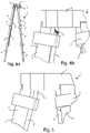
figure 4a shows a side view of the tripod offigure 1 ; -
figure 4b shows detail IVb of the tripod offigure 4a ; -
figure 5 shows a variant of the transmission element offigure 4b ; -
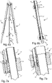
figure 6a shows a front view of the tripod offigure 1 ; -
figure 6b shows a side sectional view along the section plane Vlb - Vlb' of a leg of the tripod offigure 6a ; -
figure 7a shows detail Vila of the leg of the tripod offigure 6b ; -
figure 7b shows detail Vllb of the leg of the tripod offigure 6b ; -
figure 8 shows a perspective view of a tripod according to the invention in a second embodiment; -
figure 9 shows a perspective view of detail IX of the tripod offigure 8 ; -
figures 10a and 10b show a perspective view of a tripod according to the invention in a third embodiment respectively in an open or extended position and in a closed or retracted position; -
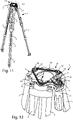
figure 11 shows a perspective view of the tripod ofFigure 10a devoid of an upper cover element; -
figure 12 shows detail XII of the tripod offigure 11 ; -
figure 13a shows a front view of the tripod ofFigure 10a ; -
figure 13b shows a side sectional view along the section plane Xlllb - Xlllb' of a leg of the tripod offigure 13a ; -
figure 14a shows detail XIVa of the leg of the tripod offigure 13b ; -
figure 14b shows detail XIVb of the leg of the tripod offigure 13b ; -
figures 15a and 15b show the locking/unlocking means offigure 14b respectively in the locking and unlocking position; -
figures 16a and 16b respectively show sectional views along the planes XVIa and XVIb of the details offigures 15a and 15b ; -
figures 17a and 17b respectively show the locking/unlocking means offigure 14a respectively in the locking and unlocking position; -
figures 18a and 18b respectively show sectional views along planes XVIIIa and XVIIIb of the details offigures 17a and 17b ; -
figure 19 shows a perspective view of the tripod according to the invention in a fourth embodiment; -
figure 20 shows detail XX offigure 19 ; -
figure 21 shows a perspective view of the tripod according to the invention in a fifth embodiment; and -
figure 22 shows detail XXII offigure 21 . - Making reference to
figures 1 - 7 , a first embodiment of a tripod according to the invention indicated bynumerical reference 1 is observed. - Said
tripod 1 has threelegs 2 connected at their upper ends to a connectingelement 3 arranged at the sub-cup. At theconnection element 3, the head for the support of the audio-video or photographic device (not shown) is mounted. - Each
leg 2 comprises three portions orsections 2', 2" and 2"', in particular concentric and telescopic. The first section 2', is fixed above the connectingelement 3, thesecond section 2" is slidably coupled to the first section 2' and the third section 2'" is slidably coupled to thesecond section 2". In other embodiments, two or more than three sections may be provided. - Said
legs 2 are configured in such a way as to assume a first retracted configuration, wherein thesections 2', 2" and 2‴ of thelegs 2 are grouped (shown infigure 1b ) and a second extended configuration, wherein thesections 2', 2" and 2" of thelegs 2 are completely extended, obtaining a maximum height of thetripod 1. The threesections 2', 2" and 2" of thetripod 1 allow to fully open the legs of the tripod in two stages of maximum extension. - All intermediate configurations between the two configurations described are equally possible, by acting on appropriate actuation means as it will be described in the following.
- The three
legs 2 of thetripod 1 are structurally the same and therefore only one of them will be described below, the same features also being valid for the others. - In the particular embodiment each
section 2', 2", 2‴ of eachleg 2 is a hollow tubular element.Such legs 2 are preferably made of metal alloys, generally aluminum, or alternatively polymers or carbon fiber. - In particular, the first section 2', coupled to the connecting
member 3, has a hollow body having a greater diameter than the outer body of thesecond section 2", so that the latter is able to slide in said hollow body of the first section 2'. In turn, thesecond section 2" has a hollow body having a greater diameter than the outer body of thethird section 2"', so that the latter is able to slide into said hollow body of thesecond section 2". -
Said tripod 1 further comprises a control element oractuation element 11 associated with motion transmission means 10 adapted to act on eachleg 2 of thetripod 1 to simultaneously lock or unlock the sliding movement of thesections 2', 2 ", 2‴ of eachleg 2 to allow partial or total extension or partial or total retraction, and thus pass from the first to the second configuration and vice versa. - The motion transmission means 10 of the
tripod 1 according to the first embodiment are in particular visible infigure 2 , as they are preferably arranged under acovering element 9 at said connectingelement 3. Said coveringelement 9 may be the sub-cup of thetripod 1. - In the specific embodiment the actuation element is a
knob 11 adapted to be rotated integrally with adrive shaft 15 that transmits the rotary motion to a plurality of first 12 and second 13 wheels, in particular friction wheels. - In other embodiments, another rotary element may be provided for transmitting the rotary motion of the
knob 11. - In addition, the actuation element may be different from the
knob 11 shown, as long as it is capable of imprinting a torque on a rotation axis. - The first section 2' of each
leg 2 comprises a first rod or connecting rod 4' arranged parallel to the first section 2', eventually it may be arranged coaxially to said first section 2'. The first rod 4' is coupled above the connectingmember 3 and below a first junction element 8' integral with the lower end of the first section 2'. - The upper end of said first rod 4' is connected to said rotary motion transmission means 10. In the particular embodiment the first end or upper end of the first rod 4' is integrally connected to the
second shaft 14 of asecond wheel 13 of themotion transmission mechanism 10. The lower end or second end of the first rod 4' is integrally coupled to the first junction element 8'. - Said first rod 4' is adapted to rotate on its rotation axis.
- During use, when the user, in particular an operator, acts on the
knob 11 imparting a torque along the axis of rotation of thefirst shaft 15, this rotary movement is transmitted through afirst wheel 12 integral with thefirst shaft 15 to a plurality ofsecond wheels 13 which in turn transmit the rotary movement to the first rod 4' of the first section 2' of eachleg 2 simultaneously. In the particular embodiment, the user acts on theknob 11 that rotates with respect to its axis of rotation, transferring the rotary motion to afirst wheel 12, through thesame shaft 15 on which they are coupled together, which transmits the rotary motion to a plurality ofsecond wheels 13 that will rotate on theirshafts 14. Thesecond wheels 13 arranged at the respective first sections 2'simultaneously transmit the rotary motion to the respective first rod 4'. - In turn, each first rod 4' transmits the locking or unlocking command to the remaining
sections 2", 2‴ of theleg 2. - In particular, each first rod 4' or connecting rod 4' is connected to the connecting
member 3 by means of a transmission element 5 (shown in particular infigure 4b ) which guarantees the transmission of the rotary motion between thewheels 13 and the first rod 4' allowing the deviation from the vertical axis of eachleg 2 of a desired angle independently of the others. In other words, thetransmission element 5 is able to transmit the rotary motion regardless of the different inclination of therelative leg 2 with respect to the axis of rotation of theshaft 14 of the respectivesecond wheel 13 arranged at saidleg 2. Thetransmission element 5 is in fact adapted to transmit the rotary motion even when the axes of rotation of theshaft 14 and the rod 4'are not aligned, for example they are inclined to each other. In the embodiment shown infigures 4a and 4b the transmission element is a cardan joint oruniversal joint 5. Alternatively, as shown inFigure 5 the transmission element is aflexible element 51, in particular elastic. - The
second section 2" is also equipped with asecond rod 4" coaxial to said first rod 4' and telescopic with respect to it. In particular, the first rod 4' has a hollow body having a greater diameter than the outer body of thesecond rod 4", so that thesecond rod 4" can slide internally to said first rod 4'. - The lower end of the first rod 4' is integrally coupled to the first junction 8'.
- The first junction 8' is provided with a screw mechanism 6 (shown in
figure 7b ) that acts on a wedge-shapedstopper 7 that acts by friction on thesecond section 2" of theleg 2 locking the linear sliding of thesecond section 2" with respect to the first section 2'. - More specifically, the first junction 8' provides a housing for the wedge-shaped
stopper 7 provided with an inclined or tiltedwall 21. When thescrew mechanism 6 rotates due to the rotation of the connecting rod 4', it causes the sliding of the wedge-shapedstopper 7 on theinclined wall 21, bringing it closer or away from thesecond section 2" and then preventing it or allowing it to slide. - In addition, the
screw mechanism 6 arranged in said first junction 8' has a hollow seat with a square cross-section having a greater size than the outer body of thesecond rod 4", also having a quadrangular cross-section, so that saidsecond rod 4" can slide but not rotate there, thus creating a prismatic guide that allows the transmission of the rotary motion while maintaining the telescopicity between the tworods 4' and 4". - The lower end of the
second rod 4" is coupled to a second connectingmember 8", integral with thesecond section 2". - The first rod 4', thanks to the first junction 8', transmits the rotary movement to the
second rod 4". Similar to thesecond section 2", also in order to lock thethird section 2‴ its is provided at thesecond junction 8"a wedge-shapedlocking stopper 7. Thesecond rod 4" at its second end or lower end is connected to ascrew mechanism 6 that acts on a wedge-shapedpad 7 that acts by friction on thethird section 2‴ of theleg 2 locking the linear sliding of thethird section 2‴ with respect to thesecond section 2". - The two connecting
rods 4', 4"running along the twosections 2', 2" of aleg 2 also create a telescopic system for adapting to the different extensions of the stages of theleg 2 of thetripod 1. - Therefore, all the
sections 2', 2", 2‴ of all thelegs 2 that make up thetripod 1 can be locked or unlocked simultaneously, by acting on asingle command 11. - In other embodiments the actuation element may be a knob or lever adapted to apply a torque to an axis. The constructive possibilities and operating principles are numerous and not limited to those illustrated here by way of example.
- For example, in the embodiment shown in
figures 19 and 20 the actuation member is alever 41, while in the embodiment offigures 21 and 22 the actuation element is a ring nut 61. - Referring to
Figures 8 and 9 , a second embodiment of thetripod 1 according to the invention is shown. It is similar to the first embodiment described, however it employs different means of transmitting therotary motion 20. Said rotary motion transmission means 20 use a plurality ofwheels flexible element 22, in particular abelt 22. - In this embodiment, therefore, the number of wheels is advantageously reduced, providing a
first wheel 12 at thefirst shaft 15 of theknob 11 and asecond wheel 13 at eachleg 2 of thetripod 1, connected by theflexible element 22. - In the particular embodiment,
additional return wheels 23 have been used to ensure the correct tensioning of theflexible element 22.Such return wheels 23 may have a diameter different from the diameter of the first 12 and second 13 wheels, in particular they have a smaller diameter. Furthermore, thesereturn wheels 23 are arranged on the connectingelement 3 according to the reciprocal arrangement of theknob 11 and thelegs 2. - A third embodiment of the
tripod 1 according to the invention is shown infigures 10 - 18 . - As can be seen, the
tripod 1 comprises threelegs 2 with multiple bars. In particular, eachleg 2 is divided into threesections 2', 2", 2"'. Wherein the first section 2' has two parallel bars coupled to the connectingmember 3 and to a first junction member 8'. Thesecond section 2" comprises two bars sliding with respect to their respective seats obtained in the first junction 8'. In addition, saidsecond section 2" is integral below to asecond junction element 8". Thethird section 2‴ comprises two bars able to slide in the two bars of thesecond section 2" with respect to said second junction element 8'. - Also in this case there are two connecting
rods 4' and 4", each integral to the first twosections 2' and 2". - The rotary motion transmission means 30 are similar to those described for the second embodiment of the tripod of
figure 11 , and instead of providing a belt, they provide achain 37 that engages a plurality oftoothed wheels 33. - In the particular embodiment, the drive means are a
knob 31 adapted to rotate with respect to an axis of rotation integral with afirst shaft 35 in turn integral with a firsttoothed wheel 32 which is adapted to transmit the rotary motion through thechain 37 to a plurality of second 33 and third 34 toothed wheels, integral with a respectivesecond shaft 36. - The
knob 31 has a substantially cylindrical body and it can be suitably used as a handle for transporting thetripod 1. - Similar to the embodiments described above, also for this embodiment the sliding of the second and
third sections 2", 2‴ is locked by a wedge-shapedstopper system 7 operated by ascrew mechanism 6. - In this case, as shown in
figures 14a - 14b , thescrew mechanism 6, comprises a sliding threadedinsert 38, capable of operating the locking pad orstopper 7 of a telescopic stage on the leg. - A slot or
seat 39 is provided on thestopper 7 wherein the threadedinsert 38 is free to slide gripped with thescrew 6 that drags the lockingstopper 7 itself along theinclined wall 21.Figures 15a, 16a, 17a and18a show the locking position of the second 2" and third 2‴ section of thetripod 1 at the first 8' and the second 8" junction, wherein the position of the lockingstopper 7 acting by friction on therelative section 2" or 2"'is observed, preventing its sliding. -
Figures 15b, 16b, 17b and18b show the unlocking position of the second 2" and third 2‴ section of thetripod 1 at the first 8' and the second 8" junction, wherein the position of the lockingstopper 7 not anymore acting by friction on therelative section 2" or 2"'is observed, which is free of sliding. - In this way, the axial and orthogonal components of the relative motion of the
stopper 7 with respect to thescrew 6 have been decoupled, ensuring that the coupling between the threadedscrew 6 and theinsert 38 can always work correctly and without excessive effort, since theinsert 38 moves only axially along thescrew 6. The other component of the motion, orthogonal to thescrew 6, and necessary to force thewedge 7 against the tubes of thesection 2", 2‴ to be braked, is made by the motion of theinsert 38 in theslot 39 obtained in thestopper 7. This allows a better locking with less actuation effort for the user. - Advantageously, the tripod according to the invention allows to speed up the time for locking/unlocking the sections of the legs of the tripod.
- Furthermore, it is advantageous to adjust the horizontality of the connecting
element 3, since the length of the threelegs 2 can be varied simultaneously by acting on a single locking/unlocking command. - The invention also allows a homogeneous and simultaneous positioning of each of the three legs with a single opening/closing manoeuvre exploiting the gravity for the fall of the sections that stops when reaching the ground.
- Another object of the invention is to speed up the levelling of the head by acting only on the control that simultaneously unlocks all the legs thus allowing its adjustment.
- The elements described for the different embodiments are illustrative only and not limiting to the specific embodiment. For example, the disclosed transmission means may be employed for all the disclosed tripods, as well as the actuating elements.
- In the above the preferred embodiments have been described and the possible variants of the present invention have been outlined, but it is to be understood that the persons skilled in the art may make modifications and changes without falling outside the relative scope of protection, as defined in the attached claims.
Claims (17)
- Tripod (1) comprisinga connecting element (3),at least three legs (2) coupled to said connecting element (3), each leg (2) being divided into at least two sections (2', 2", 2‴) able to slide with respect to each other,each leg (2) providing locking and unlocking means (4', 4", 6, 7) of the sliding movement between the sections (2', 2", 2‴) of the respective leg (2),said tripod (1) further providing an actuation element (11; 31; 41; 61) of said locking and unlocking means (4', 4", 6, 7),said tripod (1) being characterized in that said actuation element (11; 31; 41; 61) is arranged on said connecting element (3), in comprising transmission means (10; 20; 30) arranged on the connecting element (3) connected to said actuation element (11; 31; 41; 61) and to said locking/unlocking means (4', 4", 6, 7) of each leg (2) and in that said tripod (1) is configured so that by acting on said actuation element (11; 31) said transmission means (10; 20; 30) act simultaneously on said locking/unlocking means (4', 4", 6 , 7) of each leg (2) preventing/allowing the sliding movement between said sections (2', 2", 2"') of each leg (2).
- Tripod (1) according to the preceding claim, characterized in that said actuation element (11; 31; 41; 61) is able to exert a torque on said transmission means (10; 20; 30) which in turn are adapted to transmit a rotation movement to said locking/unlocking means (4', 4", 6, 7) of each leg (2).
- Tripod (1) according to claim 1 or 2, characterized in that said actuation element (11; 31; 41; 61) comprises a rotating element (11; 31; 41; 61) able to rotate integrally with a respective shaft (15; 35), in particular said rotating element (11; 31; 41; 61) is a ring nut (61) or a knob (11; 31) or a lever (41).
- Tripod (1) according to claim 2 or 3, characterized in that said transmission means (10; 20; 30) comprise a plurality of wheels (12, 13; 12, 13, 23; 32, 33, 34) adapted at transmitting a rotary motion, in particular friction wheels (12, 13, 23) or toothed wheels (32, 33, 34).
- Tripod (1) according to the preceding claim, characterized in that said transmission means (20; 30) further comprise a flexible element (22; 37) for transmitting the rotary motion between said wheels (12, 13, 23; 32, 33, 34), in particular said flexible element is a belt (22) or a chain (37).
- Tripod (1) according to any one of the preceding claims, characterized in that said locking/unlocking means (4', 4", 6, 7) comprise a locking element (7), in particular a wedge-shaped stopper (7), adapted to exert a friction force on at least one section (2 ", 2‴) of a respective leg (2) for blocking the sliding movement between the sections (2', 2", 2‴) of said leg (2).
- Tripod (1) according to the preceding claim, characterized in that, at least in correspondence with the first section (2', 2") of each leg (2), said locking/unlocking means (4', 4", 6, 7) provide a connecting rod (4', 4") adapted to act on said locking element (7).
- Tripod (1) according to claims 2 and 7, characterized in that each connecting rod (4', 4") is able to rotate along its own axis for acting on said locking element (7) when the transmission means (10; 20; 30) transmit the rotary motion exerted by the actuation element (11; 31; 41; 61).
- Tripod (1) according to claim 7 or 8, characterized in that the first connecting rod (4') arranged in correspondence with the first section (2') of each leg (2) has at a first end or upper end a transmission element (5; 51) connected to said transmission means (10; 20; 30) adapted to transmit the rotary motion from said transmission means (10; 20; 30) to said first connecting rod (4') even when they are arranged on non-coinciding rotation axes, preferably said transmission element is an universal joint (5) or a flexible element (51).
- Tripod (1) according to claim 8 or 9, characterized in that said locking/unlocking means (4', 4", 6, 7), at a second end or lower end, opposite the first end, of said connecting rod (4', 4") have a screw mechanism (6) able to act, when rotated, on said locking element (7) in order to move it away from or move it closer to at least one section (2", 2‴) for locking or unlocking its sliding movement with respect to the other sections (2', 2").
- Tripod (1) according to claims 6 and 10, characterized in that each leg (2) provides at least a first junction element (8'; 8") between two sections (2', 2"; 2", 2‴), in that each junction element (8'; 8") provides a housing for the respective wedge-shaped stopper (7) having a tilted wall (21).
- Tripod (1) according to claims 6 and 10 or according to claim 11, characterized in that said screw mechanism (6) comprises a sliding threaded insert (38), in that on said locking element (7) it is provided a seat (39) wherein said thread insert (38) is adapted to slide for displacing said locking element (7) so as to pass to a locking or unlocking position of the sliding movement between the sections (2', 2", 2") of the respective leg (2).
- Tripod (1) according to any one of the previous claims 10 - 12, characterized in that each leg (2) is divided into at least three sections (2', 2", 2"'), in that at least in correspondence with the first (2') and second (2") section it is provided a respective connecting rod (4', 4"), in that the second connecting rod (4") has a prismatic cross-section, said prismatic cross-section having a size in order to be telescopic with respect to the first connecting rod (4'), in that the screw mechanism (6) arranged at the lower end of the first connecting rod (4') has a hollow seat with a prismatic cross-section having a larger size than the outer body of the second rod (4"), so that said second rod (4") can slide but not rotate.
- Tripod (1) according to any one of the preceding claims, when dependent on claim 4, characterized in that said transmission means (10; 20; 30) provide a first wheel (12; 32) integral with a first shaft (15; 35) of said actuation element (11; 31; 41; 61) and at least one second wheel (13; 33) on said connecting element (3) at each leg (2).
- Tripod (1) according to the previous claim, characterized in that said transmission means comprise a plurality of further second wheels (13, 23, 34) adapted to transmit the rotary motion and arranged both between said first wheel (12; 32) and said second wheels (13; 33) arranged on the connecting element (5) of the respective leg (2) both between the same second wheels (13; 33) arranged on the connecting element (5) of the respective leg (2).
- Tripod (1) according to the previous claim, when dependent on claim 5, characterized in that said further wheels are idler wheels (23) adapted to guarantee the correct tensioning of said flexible element (22), preferably said idler wheels (23) have a different diameter, in particular smaller, than the diameter of the first and second wheels (12, 13).
- Tripod (1) according to any one of the claims 12 - 16, when dependent on claim 7, characterized in that each second wheel (13; 33) is integral to a respective second shaft (14; 36) and in that the first end or top end of each first connecting rod (4'), arranged at the first section (2') of the respective leg (2), is integrally connected to the respective second shaft (14; 36).
Applications Claiming Priority (1)
| Application Number | Priority Date | Filing Date | Title |
|---|---|---|---|
| IT102021000018167A IT202100018167A1 (en) | 2021-07-09 | 2021-07-09 | TRIPOD WITH LOCKING/UNLOCKING SYSTEM OF THE LEGS. |
Publications (3)
| Publication Number | Publication Date |
|---|---|
| EP4116619A1 true EP4116619A1 (en) | 2023-01-11 |
| EP4116619B1 EP4116619B1 (en) | 2025-09-10 |
| EP4116619C0 EP4116619C0 (en) | 2025-09-10 |
Family
ID=78049620
Family Applications (1)
| Application Number | Title | Priority Date | Filing Date |
|---|---|---|---|
| EP22183923.6A Active EP4116619B1 (en) | 2021-07-09 | 2022-07-08 | Tripod with system for locking/unlocking the legs |
Country Status (4)
| Country | Link |
|---|---|
| US (1) | US11774035B2 (en) |
| EP (1) | EP4116619B1 (en) |
| CN (1) | CN115596969A (en) |
| IT (1) | IT202100018167A1 (en) |
Families Citing this family (7)
| Publication number | Priority date | Publication date | Assignee | Title |
|---|---|---|---|---|
| JP2022553395A (en) * | 2019-10-23 | 2022-12-22 | ヴァイテック イメージング ソリューションズ エス・ピー・エー | Tripods for video/photography equipment |
| BG67471B1 (en) * | 2019-12-18 | 2022-10-31 | Георгиев Захариев Стойко | Photography equipmenttripod |
| JP1705262S (en) * | 2021-01-22 | 2022-01-18 | Rescue tripod | |
| CN218153087U (en) * | 2022-09-29 | 2022-12-27 | 深圳欧森隆科创有限公司 | Telescopic foot and support |
| GB202214645D0 (en) * | 2022-10-05 | 2022-11-16 | Safehold Ltd | Tripod |
| US12516773B2 (en) * | 2023-04-06 | 2026-01-06 | Guangdong Sirui Optical Co., Ltd. | Extendable support leg |
| CN117404580B (en) * | 2023-10-18 | 2026-04-28 | 天津博泰天宇科技发展有限公司 | A tripod |
Citations (4)
| Publication number | Priority date | Publication date | Assignee | Title |
|---|---|---|---|---|
| EP1027554B1 (en) * | 1997-10-20 | 2004-02-11 | Autocue, Inc. | Dual-stage quick release leg and tripod |
| US20040206879A1 (en) * | 2001-05-10 | 2004-10-21 | Steyn Jasper L | Multi-legged equipment support for cameras, spotting telescopes and the like and jam-plate lock for same |
| WO2011026444A1 (en) * | 2009-09-07 | 2011-03-10 | Fung Ngo Leung | Supporting device |
| US20210010637A1 (en) * | 2019-07-08 | 2021-01-14 | Shengbin HE | Single-hand-lever Double-joint-control Adjustable Hoop Type Bearing Frame |
Family Cites Families (6)
| Publication number | Priority date | Publication date | Assignee | Title |
|---|---|---|---|---|
| US6082685A (en) * | 1996-06-07 | 2000-07-04 | Sachtler Ag | Telescopic stand |
| US6286795B1 (en) * | 1998-10-20 | 2001-09-11 | Autocue, Inc. | Dual-stage quick release leg and tripod |
| ATE537404T1 (en) * | 2009-05-11 | 2011-12-15 | Camera Dynamics Gmbh | TRIPOD, ESPECIALLY CAMERA TRIPOD |
| US10898252B2 (en) | 2017-11-09 | 2021-01-26 | Globus Medical, Inc. | Surgical robotic systems for bending surgical rods, and related methods and devices |
| CN112771301B (en) * | 2018-09-26 | 2023-02-28 | 威泰克影像解决方案股份公司 | Tripod for video and photographic equipment |
| JP2022553395A (en) * | 2019-10-23 | 2022-12-22 | ヴァイテック イメージング ソリューションズ エス・ピー・エー | Tripods for video/photography equipment |
-
2021
- 2021-07-09 IT IT102021000018167A patent/IT202100018167A1/en unknown
-
2022
- 2022-07-08 EP EP22183923.6A patent/EP4116619B1/en active Active
- 2022-07-08 US US17/811,558 patent/US11774035B2/en active Active
- 2022-07-11 CN CN202210812949.6A patent/CN115596969A/en active Pending
Patent Citations (4)
| Publication number | Priority date | Publication date | Assignee | Title |
|---|---|---|---|---|
| EP1027554B1 (en) * | 1997-10-20 | 2004-02-11 | Autocue, Inc. | Dual-stage quick release leg and tripod |
| US20040206879A1 (en) * | 2001-05-10 | 2004-10-21 | Steyn Jasper L | Multi-legged equipment support for cameras, spotting telescopes and the like and jam-plate lock for same |
| WO2011026444A1 (en) * | 2009-09-07 | 2011-03-10 | Fung Ngo Leung | Supporting device |
| US20210010637A1 (en) * | 2019-07-08 | 2021-01-14 | Shengbin HE | Single-hand-lever Double-joint-control Adjustable Hoop Type Bearing Frame |
Also Published As
| Publication number | Publication date |
|---|---|
| CN115596969A (en) | 2023-01-13 |
| EP4116619B1 (en) | 2025-09-10 |
| IT202100018167A1 (en) | 2023-01-09 |
| US11774035B2 (en) | 2023-10-03 |
| US20230022365A1 (en) | 2023-01-26 |
| EP4116619C0 (en) | 2025-09-10 |
Similar Documents
| Publication | Publication Date | Title |
|---|---|---|
| EP4116619A1 (en) | Tripod with system for locking/unlocking the legs | |
| EP3814671B1 (en) | Support device for video/photographic equipment | |
| US11131910B2 (en) | Supporting mechanism, and adjusting device and gimbal having the same | |
| US6367121B1 (en) | Adjustable length handle for flat finishers | |
| US9684228B2 (en) | Dynamic rotation monopod | |
| EP3857111B1 (en) | A tripod for video-photographic equipment | |
| US6260238B1 (en) | Adjustable length handle for flat finishers | |
| JP2010262280A (en) | Stand, in particular camera stand | |
| EP4078010B1 (en) | Tripod for shooting equipment | |
| CN107110419A (en) | Head framework and head and filming apparatus with the head framework | |
| US12596293B2 (en) | Light adjustment device and photography auxiliary device | |
| US12449089B2 (en) | One-step locking stand | |
| US7000875B2 (en) | Tripod | |
| WO2019000549A1 (en) | Support frame, tripod assembly and unmanned aerial vehicle | |
| DE102009006789B4 (en) | Telescopic support device with clamping device | |
| CN113701004B (en) | Photographic equipment supporting device | |
| EP4361490A1 (en) | A quick release device | |
| EP4443039A1 (en) | An extendable support leg | |
| CN109154415B (en) | Orientable modules for video/photography equipment | |
| JP2025027958A (en) | Quick height adjustment for imaging equipment support | |
| JPH0553038A (en) | Focusing rail |
Legal Events
| Date | Code | Title | Description |
|---|---|---|---|
| PUAI | Public reference made under article 153(3) epc to a published international application that has entered the european phase |
Free format text: ORIGINAL CODE: 0009012 |
|
| STAA | Information on the status of an ep patent application or granted ep patent |
Free format text: STATUS: THE APPLICATION HAS BEEN PUBLISHED |
|
| AK | Designated contracting states |
Kind code of ref document: A1 Designated state(s): AL AT BE BG CH CY CZ DE DK EE ES FI FR GB GR HR HU IE IS IT LI LT LU LV MC MK MT NL NO PL PT RO RS SE SI SK SM TR |
|
| P01 | Opt-out of the competence of the unified patent court (upc) registered |
Effective date: 20230516 |
|
| STAA | Information on the status of an ep patent application or granted ep patent |
Free format text: STATUS: REQUEST FOR EXAMINATION WAS MADE |
|
| 17P | Request for examination filed |
Effective date: 20230706 |
|
| RBV | Designated contracting states (corrected) |
Designated state(s): AL AT BE BG CH CY CZ DE DK EE ES FI FR GB GR HR HU IE IS IT LI LT LU LV MC MK MT NL NO PL PT RO RS SE SI SK SM TR |
|
| GRAP | Despatch of communication of intention to grant a patent |
Free format text: ORIGINAL CODE: EPIDOSNIGR1 |
|
| STAA | Information on the status of an ep patent application or granted ep patent |
Free format text: STATUS: GRANT OF PATENT IS INTENDED |
|
| INTG | Intention to grant announced |
Effective date: 20250514 |
|
| RAP3 | Party data changed (applicant data changed or rights of an application transferred) |
Owner name: CARTONI S.P.A.- SOCIETA' BENEFIT |
|
| GRAS | Grant fee paid |
Free format text: ORIGINAL CODE: EPIDOSNIGR3 |
|
| GRAA | (expected) grant |
Free format text: ORIGINAL CODE: 0009210 |
|
| STAA | Information on the status of an ep patent application or granted ep patent |
Free format text: STATUS: THE PATENT HAS BEEN GRANTED |
|
| AK | Designated contracting states |
Kind code of ref document: B1 Designated state(s): AL AT BE BG CH CY CZ DE DK EE ES FI FR GB GR HR HU IE IS IT LI LT LU LV MC MK MT NL NO PL PT RO RS SE SI SK SM TR |
|
| REG | Reference to a national code |
Ref country code: GB Ref legal event code: FG4D |
|
| REG | Reference to a national code |
Ref country code: CH Ref legal event code: EP |
|
| REG | Reference to a national code |
Ref country code: DE Ref legal event code: R096 Ref document number: 602022021067 Country of ref document: DE |
|
| REG | Reference to a national code |
Ref country code: IE Ref legal event code: FG4D |
|
| U01 | Request for unitary effect filed |
Effective date: 20251003 |
|
| U07 | Unitary effect registered |
Designated state(s): AT BE BG DE DK EE FI FR IT LT LU LV MT NL PT RO SE SI Effective date: 20251014 |
|
| PG25 | Lapsed in a contracting state [announced via postgrant information from national office to epo] |
Ref country code: NO Free format text: LAPSE BECAUSE OF FAILURE TO SUBMIT A TRANSLATION OF THE DESCRIPTION OR TO PAY THE FEE WITHIN THE PRESCRIBED TIME-LIMIT Effective date: 20251210 |
|
| PG25 | Lapsed in a contracting state [announced via postgrant information from national office to epo] |
Ref country code: HR Free format text: LAPSE BECAUSE OF FAILURE TO SUBMIT A TRANSLATION OF THE DESCRIPTION OR TO PAY THE FEE WITHIN THE PRESCRIBED TIME-LIMIT Effective date: 20250910 |
|
| PG25 | Lapsed in a contracting state [announced via postgrant information from national office to epo] |
Ref country code: GR Free format text: LAPSE BECAUSE OF FAILURE TO SUBMIT A TRANSLATION OF THE DESCRIPTION OR TO PAY THE FEE WITHIN THE PRESCRIBED TIME-LIMIT Effective date: 20251211 |
|
| PG25 | Lapsed in a contracting state [announced via postgrant information from national office to epo] |
Ref country code: PL Free format text: LAPSE BECAUSE OF FAILURE TO SUBMIT A TRANSLATION OF THE DESCRIPTION OR TO PAY THE FEE WITHIN THE PRESCRIBED TIME-LIMIT Effective date: 20250910 |
|
| PG25 | Lapsed in a contracting state [announced via postgrant information from national office to epo] |
Ref country code: RS Free format text: LAPSE BECAUSE OF FAILURE TO SUBMIT A TRANSLATION OF THE DESCRIPTION OR TO PAY THE FEE WITHIN THE PRESCRIBED TIME-LIMIT Effective date: 20251210 |
|
| PG25 | Lapsed in a contracting state [announced via postgrant information from national office to epo] |
Ref country code: ES Free format text: LAPSE BECAUSE OF FAILURE TO SUBMIT A TRANSLATION OF THE DESCRIPTION OR TO PAY THE FEE WITHIN THE PRESCRIBED TIME-LIMIT Effective date: 20250910 |
|
| PG25 | Lapsed in a contracting state [announced via postgrant information from national office to epo] |
Ref country code: SM Free format text: LAPSE BECAUSE OF FAILURE TO SUBMIT A TRANSLATION OF THE DESCRIPTION OR TO PAY THE FEE WITHIN THE PRESCRIBED TIME-LIMIT Effective date: 20250910 |
|
| PG25 | Lapsed in a contracting state [announced via postgrant information from national office to epo] |
Ref country code: IS Free format text: LAPSE BECAUSE OF FAILURE TO SUBMIT A TRANSLATION OF THE DESCRIPTION OR TO PAY THE FEE WITHIN THE PRESCRIBED TIME-LIMIT Effective date: 20260110 |
|
| PG25 | Lapsed in a contracting state [announced via postgrant information from national office to epo] |
Ref country code: CZ Free format text: LAPSE BECAUSE OF FAILURE TO SUBMIT A TRANSLATION OF THE DESCRIPTION OR TO PAY THE FEE WITHIN THE PRESCRIBED TIME-LIMIT Effective date: 20250910 |
|
| PG25 | Lapsed in a contracting state [announced via postgrant information from national office to epo] |
Ref country code: SK Free format text: LAPSE BECAUSE OF FAILURE TO SUBMIT A TRANSLATION OF THE DESCRIPTION OR TO PAY THE FEE WITHIN THE PRESCRIBED TIME-LIMIT Effective date: 20250910 |