EP4116579A1 - Component platform lock with collets and method for holding a wind turbine blade component - Google Patents
Component platform lock with collets and method for holding a wind turbine blade component Download PDFInfo
- Publication number
- EP4116579A1 EP4116579A1 EP21184248.9A EP21184248A EP4116579A1 EP 4116579 A1 EP4116579 A1 EP 4116579A1 EP 21184248 A EP21184248 A EP 21184248A EP 4116579 A1 EP4116579 A1 EP 4116579A1
- Authority
- EP
- European Patent Office
- Prior art keywords
- wind turbine
- component
- turbine blade
- collet
- inner cone
- Prior art date
- Legal status (The legal status is an assumption and is not a legal conclusion. Google has not performed a legal analysis and makes no representation as to the accuracy of the status listed.)
- Granted
Links
Images




Classifications
-
- F—MECHANICAL ENGINEERING; LIGHTING; HEATING; WEAPONS; BLASTING
- F03—MACHINES OR ENGINES FOR LIQUIDS; WIND, SPRING, OR WEIGHT MOTORS; PRODUCING MECHANICAL POWER OR A REACTIVE PROPULSIVE THRUST, NOT OTHERWISE PROVIDED FOR
- F03D—WIND MOTORS
- F03D13/00—Assembly, mounting or commissioning of wind motors; Arrangements specially adapted for transporting wind motor components
- F03D13/10—Assembly of wind motors; Arrangements for erecting wind motors
- F03D13/104—Rotor installation, e.g. installation of blades
-
- F—MECHANICAL ENGINEERING; LIGHTING; HEATING; WEAPONS; BLASTING
- F03—MACHINES OR ENGINES FOR LIQUIDS; WIND, SPRING, OR WEIGHT MOTORS; PRODUCING MECHANICAL POWER OR A REACTIVE PROPULSIVE THRUST, NOT OTHERWISE PROVIDED FOR
- F03D—WIND MOTORS
- F03D13/00—Assembly, mounting or commissioning of wind motors; Arrangements specially adapted for transporting wind motor components
- F03D13/10—Assembly of wind motors; Arrangements for erecting wind motors
-
- F—MECHANICAL ENGINEERING; LIGHTING; HEATING; WEAPONS; BLASTING
- F05—INDEXING SCHEMES RELATING TO ENGINES OR PUMPS IN VARIOUS SUBCLASSES OF CLASSES F01-F04
- F05B—INDEXING SCHEME RELATING TO WIND, SPRING, WEIGHT, INERTIA OR LIKE MOTORS, TO MACHINES OR ENGINES FOR LIQUIDS COVERED BY SUBCLASSES F03B, F03D AND F03G
- F05B2230/00—Manufacture
- F05B2230/60—Assembly methods
- F05B2230/604—Assembly methods using positioning or alignment devices for aligning or centering, e.g. pins
-
- F—MECHANICAL ENGINEERING; LIGHTING; HEATING; WEAPONS; BLASTING
- F05—INDEXING SCHEMES RELATING TO ENGINES OR PUMPS IN VARIOUS SUBCLASSES OF CLASSES F01-F04
- F05B—INDEXING SCHEME RELATING TO WIND, SPRING, WEIGHT, INERTIA OR LIKE MOTORS, TO MACHINES OR ENGINES FOR LIQUIDS COVERED BY SUBCLASSES F03B, F03D AND F03G
- F05B2240/00—Components
- F05B2240/20—Rotors
- F05B2240/30—Characteristics of rotor blades, i.e. of any element transforming dynamic fluid energy to or from rotational energy and being attached to a rotor
- F05B2240/302—Segmented or sectional blades
-
- Y—GENERAL TAGGING OF NEW TECHNOLOGICAL DEVELOPMENTS; GENERAL TAGGING OF CROSS-SECTIONAL TECHNOLOGIES SPANNING OVER SEVERAL SECTIONS OF THE IPC; TECHNICAL SUBJECTS COVERED BY FORMER USPC CROSS-REFERENCE ART COLLECTIONS [XRACs] AND DIGESTS
- Y02—TECHNOLOGIES OR APPLICATIONS FOR MITIGATION OR ADAPTATION AGAINST CLIMATE CHANGE
- Y02E—REDUCTION OF GREENHOUSE GAS [GHG] EMISSIONS, RELATED TO ENERGY GENERATION, TRANSMISSION OR DISTRIBUTION
- Y02E10/00—Energy generation through renewable energy sources
- Y02E10/70—Wind energy
- Y02E10/72—Wind turbines with rotation axis in wind direction
Definitions
- the present disclosure relates to a system and method for holding a wind turbine blade component during attachment to a wind turbine blade shell part.
- a receiver on one segment and a spar beam that is inserted into the receiver in a different segment may be used to attach different segments of the wind turbine blade to each other, see for example, WO 2020/180601 A1 .
- Wind turbine blades comprise a shell part and may comprise wind turbine blade component part(s), such as the receiver of the segmented wind turbine blade, as described before, which are to be attached to the shell part during a bonding process. During attachment of the wind turbine blade component to the shell part, the wind turbine blade component is to be held in place relative to the shell part.
- the component platform lock may comprise a housing.
- the component platform lock may comprise a first moving pin.
- the first moving pin may comprise a first inner cone stud having a first diameter at a first section and a second diameter at a second section. The first diameter being larger than the second diameter.
- the first moving pin may comprise a first collet having an expanding section surrounding the first inner cone stud and configured to move along the first inner cone stud between the second section and the first section. The expanding section of the first collet will contract and expand based on the diameter of the cone stud.
- the wind turbine blade component may be held by a jig or other holding devices, and the component platform lock may lock the wind turbine blade component to the holding device. Furthermore, the disclosed component platform lock may be disengaged (remotely) after the attachment process of the wind turbine blade component is completed.
- the wind turbine blade component e.g. if being a receiver for coupling of blade parts of a segmented blade, may contain bushings for the inserting of a pin lock, e.g. to lock the receiver to a spar beam. These bushings can thereby also be used, by the disclosed component platform lock, to hold/lock the receiver to the holding device during the wind turbine blade component's bonding with the shell part.
- the platform lock limits or avoids exertion of any axial forces to the bushings, and that it is able to release and/or retract from the bushings. And further that the component platform lock functions even if the wind turbine blade component has large attachment tolerances.
- the component platform lock may comprise a first actuator configured to move the first moving pin, such as to obtain a contracted state wherein the first collet is located within the housing, and an extended state wherein the first collet extends out of the housing.
- the component platform lock may comprise a second actuator configured to move the first inner cone stud relative to the first collet, such as to obtain a relaxed state wherein the expanding section of the first collet is retracted and surrounds the second section of the first inner cone stud having the second diameter, and an expanded state wherein the expanding section of the first collet is expanded and surrounds the first section of the first inner cone stud having the first diameter, and wherein in the expanded state, the expanding section is configured to engage and hold the wind turbine blade component.
- a second actuator configured to move the first inner cone stud relative to the first collet, such as to obtain a relaxed state wherein the expanding section of the first collet is retracted and surrounds the second section of the first inner cone stud having the second diameter, and an expanded state wherein the expanding section of the first collet is expanded and surrounds the first section of the first inner cone stud having the first diameter, and wherein in the expanded state, the expanding section is configured to engage and hold the wind turbine blade component.
- the component platform lock is advantageous since it ensures that the locking mechanism in the form of the first collet can be driven into a bushing of the wind turbine blade component without or with a very limited need for exerting any axial forces and allows for larger tolerances of the bushing, since the first collet may be expanded until a sufficient lock is achieved.
- the release and retracting of the lock are further easier as it can be completed by the same mechanism for engaging the bushing. Since the first collet expands from a relaxed state to an expanded state within the bushing, deformation of the bushing is less likely since the first collet is extended when its diameter is smaller than the bushing.
- the component platform lock may further comprise a second moving pin.
- the second moving pin may comprise a second inner cone stud.
- the second inner cone stud may have a first diameter at a first section and a second diameter at a second section of the second cone stud.
- the first diameter may be larger than the second diameter.
- a second collet may have an expanding section surrounding the second inner cone stud and configured to move along the second inner cone stud.
- incorporation of a second cone stud may facilitate that the component is held firmly and, in some embodiments, ensure sufficient engagement between the component platform lock and the wind turbine blade component. Further, it allows for two engagements points leading to better stability.
- the wind turbine blade component is a receiver for a segmented wind turbine.
- a receiver may comprise one or more, such as two, bushings for the attachment of a pin. Having a first and a second collet allows for the use of two (e.g. opposite) bushings of the receiver to hold the receiver during bonding with the blade shell.
- the first actuator or a third actuator may be configured to move the second moving pin, e.g. to obtain a contracted state wherein the second collet is located within the housing, and an extended state wherein the second collet extends out of the housing.
- the second actuator or a fourth actuator may be configured to move the second inner cone stud relative to the second collet, e.g. to obtain a relaxed state wherein the expanding section of the second collet is retracted and surrounds the second section of the second inner cone stud having the second diameter, and an expanded state wherein the expanding section of the second collet is expanded and surrounds the first section of the second inner cone stud having the first diameter, and wherein in the expanded state, the expanding section of the second collet is configured to engage and hold the wind turbine blade component.
- the first and second moving pin extend in opposite directions. This may allow the platform lock to be used in embodiments where the wind turbine blade component is a receiver in a segmented wind turbine blade.
- the component platform lock may further comprise an alignment sensor for aligning the first and second moving pin with bushings of the wind turbine blade component.
- the component platform lock may further comprise one or more force sensors measuring the force exerted by the second and/or fourth actuator.
- the component platform lock may further comprise one or more extension sensors for monitoring the extension of the first and/or second moving pin.
- the extension sensor may monitor the position of the first and/or second moving pin, e.g. relative to the housing.
- the first, second, third and/or fourth actuator are hydraulic, pneumatic, electrical or mechanical.
- first and/or second inner cone stud are conical in shape.
- first and/or second inner cone stud may be decreasing linearly in diameter from the first section to the second section.
- a system for attaching a wind turbine blade component to a surface of a wind turbine blade shell part at a component attachment position is provided.
- the system may comprise a blade shell part support for supporting the blade shell part.
- the system may comprise a jig.
- the jig may comprise a jig base.
- the jig may comprise a component platform comprising a component platform lock for receiving and holding the wind turbine blade component in a first position above at least a part of the blade shell part.
- the component platform lock of the system may be the component platform lock as described in relation to the first aspect.
- the component platform may be arranged on the jig base and may be at least vertically displaceable relative to the jig base by displacement means to allow the wind turbine blade component to be lowered from the first position to a component attachment position.
- a method for holding a wind turbine blade component during attachment of the wind turbine blade component to a wind turbine blade shell part is provided.
- the wind turbine blade component may comprise a cavity containing one or more bushings, e.g. at the cavity's sidewalls.
- the method may comprise providing a jig comprising a component platform lock, such as the component platform lock as described in relation to the first aspect.
- the method may comprise moving the component platform lock into the cavity of the wind turbine blade component.
- the method may comprise extending the first moving pin from the contracted state to the extended state to place the first moving pin into a busing of the one or more bushings of the wind turbine blade component.
- the method may comprise expanding the first collet from its relaxed state into its expanded state by moving the first inner cone stud to expand the first collet in the bushing to engage and hold the wind turbine blade component.
- the method may comprise positioning the wind turbine blade component by use of the jig to a component attachment position relative to the wind turbine blade shell part.
- the method may comprise retracting the first collet into its relaxed state to disengage the bushing after attachment of the wind turbine blade component, retracting the first moving pin, and/or moving the component platform lock out of the cavity of the wind turbine blade component.
- the method may comprise providing the jig with the component platform lock having the first and second moving pin, first and second inner cone stud, and first and second collets.
- the method may comprise extending the second moving pin from the contracted state to the extended state to place the first moving pin into a second bushing of the one or more bushings of the wind turbine blade component.
- the method may comprise expanding the second collet from its relaxed state into its expanded state by moving the second inner cone stud to expand the second collet in the second bushing to engage and hold the wind turbine blade component.
- the method may further comprise retracting the second collet into its relaxed state, e.g. to disengage the second bushing after attachment of the wind turbine blade component.
- the method may further comprise retracting the second moving pin.
- the method further comprises monitoring the expansions of the collets by measuring the force(s) exerted by the second and/or fourth actuator and optionally stopping the expansion when the force exerted reaches a threshold.
- the method may further comprise, e.g. as part of the step of extending the first and/or second moving pin into the bushing, using the alignment sensor(s) to align the first and/or second moving pin with the bushing(s) of the wind turbine blade component.
- the method may further comprise a step of monitoring the extension of the first and/or second moving pin by the extension sensor(s).
- Figure 1 illustrates a conventional modern upwind wind turbine 2 according to the so-called "Danish concept" with a tower 4, a nacelle 6 and a rotor with a substantially horizontal rotor shaft which may include a tilt angle of a few degrees.
- the rotor includes a hub 8 and three blades 10 extending radially from the hub 8, each having a blade root 16 nearest the hub and a blade tip 14 furthest from the hub 8.
- FIG. 2 shows a schematic view of an exemplary wind turbine blade 10.
- the wind turbine blade 10 has the shape of a conventional wind turbine blade with a root end 17 and a tip end 15 and comprises a root region 30 closest to the hub, a profiled or an airfoil region 34 furthest away from the hub and a transition region 32 between the root region 30 and the airfoil region 34.
- the blade 10 comprises a leading edge 18 facing the direction of rotation of the blade 10, when the blade is mounted on the hub 8, and a trailing edge 20 facing the opposite direction of the leading edge 18.
- the airfoil region 34 (also called the profiled region) has an ideal or almost ideal blade shape with respect to generating lift, whereas the root region 30 due to structural considerations has a substantially circular or elliptical cross-section, which for instance makes it easier and safer to mount the blade 10 to the hub.
- the diameter (or the chord) of the root region 30 may be constant along the entire root region 30.
- the transition region 32 has a transitional profile gradually changing from the circular or elliptical shape of the root region 30 to the airfoil profile of the airfoil region 34.
- the chord length of the transition region 32 typically increases with increasing distance r from the hub.
- the airfoil region 34 has an airfoil profile with a chord extending between the leading edge 18 and the trailing edge 20 of the blade 10. The width of the chord decreases with increasing distance r from the hub.
- a shoulder 40 of the blade 10 is defined as the position, where the blade 10 has its largest chord length.
- the shoulder 40 is typically provided at the boundary between the transition region 32 and the airfoil region 34.
- the wind turbine blade may consist of a shell part, either a pressure side shell part 36 or suction side shell part 38, wherein is attached a wind turbine blade component 44.
- the shell part and the wind turbine blade component may be separately manufactured and attached to each other during a bonding process.
- the wind turbine blade component 44 is held still on the shell part 36, 38 during the attachment process to ensure that the blade shell 36, 38 does not get damaged or deformed and to ensure that the receiver is located at the correct location on the shell part.
- the wind turbine blade component 44 contains a number of bushings 68 to, in some embodiments, attach a first and a second blade segment 96, 98 together by use of a pin.
- the bushings are located within a cavity 92 of the wind turbine blade component.
- the cavity is adapted to receive a beam 94 with bushings that align with the bushings of the wind turbine blade component 44.
- a pin 100 is then inserted through the beam 94 and the wind turbine blade component 44 to secure the segments 96, 98 together as seen in Figure 3B ).
- a more elaborate example of such segmented wind turbine blade may also be found in WO 2020/180601 A1 .
- the wind turbine blade component is therefore a receiver of a segmented wind turbine blade and is adapted to receive a pin lock, the pin lock being placed through the bushing of the wind turbine component.
- These bushings 68 can also be used to hold the wind turbine blade component during attachment with the blade shell part with a component platform lock.
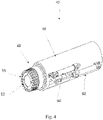
- a component platform lock 42 as shown in Figure 4 is provided.
- the component platform lock 42 comprises a housing 46 and a first moving pin 48 that comprises a first inner cone stud 52.
- the first inner cone stud 52 has a first diameter at a first section 80 and a second diameter at a second section 82, the first diameter being larger than the second diameter, so the first inner cone stud 52 is tapered.
- a first collet 56 surrounds the first inner cone stud 52 and is adapted to move along the first inner cone stud 52 between the first section 80 and the second section 82.
- the first collet 56 will expand and contract based on the location of an expanding section 84 of the first collet 56 relative to the inner cone stud 52.
- the size of the first collet 56 is therefore controllable based on its relative location on the first inner cone stud 54.
- the first collet 56 is therefore able to be in at least two states, a relaxed state where the first collet 56 is retracted and the expanding section 84 surrounds the second section 82 of the first inner cone stud 52 and an expanded state, where the first collet 56 is expanded and surrounds the first section 80 of the inner cone stud 52.
- the diameter of the first inner cone stud 52 is such that when the first collet 56 surrounds the first section 80, the combined diameter of the first collet 56 and the inner cone stud 52 is such that the first collet 56 engages the bushings 68 on the wind turbine blade component 44 (see Fig. 3 ).
- a first actuator 60 is attached to the first moving pin 48 in order to move the first collet 56 in and out of the bushings, such that the first moving pin 48 can be in at least two states.
- a contracted state where the first collet 56 is contained in the housing 46 and an extended state, wherein the first collet 56 is extended into the bushings 68.
- the first inner cone stud 52 is in some embodiments conical in shape, with a decreasing diameter from the first section 80 to the second section 82. This allows the first inner cone stud 52 to retract, moving the expanding section 84 of the first collet 56 from the second section 82 towards the first section 80 and ensuring that the first collet 56 engages the bushings 68 with adequate force. This means that the first collet 56 will expand into an inner face of the bushings 68, locking the wind turbine blade component 44 in place.
- a second actuator 62 is attached to the first inner cone stud 52, such that the first inner cone stud 52 can move relative to the first collet 56.
- the first collet 56 is therefore able to expand and engage bushings 68 of the wind turbine blade component 44 and is able to disengage the bushings by moving the first inner cone stud 52.
- the component platform lock 42 is able to hold the wind turbine blade component 44 at one engagement point, however, as shown in Figure 7 , it may in some embodiments be more advantageous to hold the wind turbine blade component at two or more engagement points, e.g. opposite engagement points.
- the component platform lock may comprise a second moving pin 50 comprising a second inner cone stud 54 attached to the second moving pin 50.
- the second inner cone stud 54 has a first diameter at a first section 80 and a second diameter at a second section 82, as seen in Figure 5 , and is in some embodiments identical to the first inner cone stud 52, as previously described.
- the first diameter is larger than the second diameter.
- a second collet 58 having an expanding section 84 surrounds the second inner stud 54 and is configured to move along the second inner cone stud 54.
- the second moving pin 50 can be moved by the first actuator 60 (see Fig. 4 ), which also moved the first moving pin 48. Thus, the first moving pin 48 and the second moving pin 50 may be moved together.
- the second moving pin 50 may be moved by a third actuator 70. Movement of the second moving pin 50 may be performed to obtain a contracted state wherein the second collet 58 is located within the housing 46, and to obtain an extended state wherein the second collet 58 is extended out of the housing 46.
- the second inner cone stud 54 can be moved relative to the second collet 58 by the second actuator 62 (see Fig. 4 ), which also moved the first inner cone stud 52. Thus, the first inner cone stud 52 and the second inner cone stud 54 may be moved together.
- the second inner cone stud 54 may be moved relative to the second collet 58 by a fourth actuator 72.
- the second inner cone stud 52 may be moved relative to the second collet 58 to obtain a relaxed state wherein the expanding section 84 of the second collet is retracted and surrounds the second section 82 of the second inner cone stud 54 having the second diameter, and to obtain an expanded state wherein the expanding section 84 of the second collet surrounds the first section of the second inner cone stud having the first diameter and configured to engage and hold the wind turbine blade component.
- the second moving pin 50 is in some embodiments of equal construction as the first moving pin 48.
- the first 60, second 62, third 70 and/or fourth actuator 72 are in some embodiments hydraulic, pneumatics, electrical or mechanical.
- the component platform lock 42 can engage the wind turbine blade component at two engagement points, which will in some embodiments give better stability.
- the first and second moving pin 48, 50 may extend in opposite directions. This gives a symmetrically distribution of forces and further allows the component platform lock to engage in already existing bushings of an exemplary receiver of a segmented wind turbine blade, being assembled with a pin joint.
- the first and second moving pin 48, 50 can in some embodiments move independently from each other, such that they can extend asymmetrical into the bushings 68 of the wind turbine blade component 44. This allows the first and second collets 56, 58 to be adjusted to the individual bushings.
- the first and second moving pin 48, 50 being able to move independently further facilitates easier alignment, in that the first moving pin 48 may be aligned and extended first, and afterwards the second moving pin 50 may be aligned and extended.
- FIG. 8 A cross-sectional view of the component platform lock is shown in Figure 8 , wherein it is shown that the first and second collets 56, 58 in some embodiments may contain a flange 88 (also illustrated in Fig. 6 ) that is adapted to be locked to the first and second moving pin 48, 50 by a locking mechanism 90. This ensures that the first and second collets 56, 58 and respectively the first and second inner cone studs 52, 54 can be moved relative to each other, by holding the first and second collet 56, 58 in place.
- piston rings 78 are used in order to ensure that the moving pin 48, 50 can move easier from the retracted state to the extended state.
- FIG. 9A shows the configuration wherein the first and second moving pins 48, 50 are retracted and the first and second collets 56, 58 are within the housing.
- 9B the first and second moving pin 48, 50 are extended out of the housing and the first and second collets 56, 58 are in their relaxed state, having a smaller diameter.
- 9C the first and second collets 56, 58 are in their expanded state, where they have a bigger diameter than in their relaxed state, such that they can expand into the bushings of the wind turbine blade component.
- the inner cone studs are pushed outwards, i.e. away from the housing 46, to change the state of the collets from the extended state to the relaxed state, and the inner cone studs are retracted, i.e. towards the housing 46, to change the state of the collets from the relaxed state to the extended state.
- the inner cone studs are opposite, such that they are retracted, i.e. towards the housing 46, to change the state of the collets from the extended state to the relaxed state, and pushed outwards, i.e. away from the housing 46, to change the state of the collets from the relaxed state to the extended state.
- the component platform lock could comprise an alignment sensor for aligning the first and/or the second moving pin with the bushings on the wind turbine blade component during the extension of the first and second moving pin into the bushings.
- a force sensor can measure the force exerted by the second and/or fourth actuator to ensure that the first and/or second collets engage the bushings with the correct force, such that the component platform lock sufficiently holds the wind turbine blade component.
- an extension sensor can monitor the extension of the first and/or second moving pin to ensure that the first and second collets are sufficiently within the bushings.
- the component platform lock can form part of a system for attaching a wind turbine blade component to a surface of a wind turbine blade shell part at a component attachment position, the system comprising a blade shell part support 106 for supporting the blade shell part, a jig 104, see Figure 10 , comprising a jig base 102, a component platform 86 which comprises a component platform lock 42 for receiving and holding the wind turbine blade component in a first position above at least a part of the blade shell part, the component platform being arranged on the jig base 102 and being at least vertically displaceable relative to the jig base 102 by displacement means to allow the wind turbine blade component to be lowered from the first position to the component attachment position.
- the component platform is also displaceable in a horizonal direction, such as by tracks.
- the component platform lock 42 may be disposed within the jig, with its collets being able to extend out from the holes shown in the jig 104 to lock into the bushing 68 as shown on the wind turbine component 44 within the cavity of the wind turbine component 44.
- the jig 104 can therefore hold the wind turbine blade component 44 in relation to the wind turbine shell part, by moving the component platform lock into a cavity of the wind turbine blade component, extending the first and/or second moving pin from the contracted state to the extended state to place the first and/or second moving pin into the bushing(s) of the wind turbine blade component, expanding the first and second collet from their relaxed state into their expanded state by moving the first inner cone stud to expand the first and second collets into the bushings to engage and hold the wind turbine blade component, and positioning the wind turbine blade component by use of the jig to an attachment position relative to the wind turbine blade shell part.
- the first and second collet After the attachment of the wind turbine blade component, the first and second collet is retracted into their relaxed state to disengage the bushings by movement of the inner cone stud relative to the collets. The first and second moving pin are thereafter retracted. The component platform lock can then be moved out of the cavity of the wind turbine blade component.
- first, second, third, “fourth”, “primary”, “secondary”, “tertiary” etc. does not imply any particular order or importance but are included to identify individual elements. Furthermore, the labelling of a first element does not imply the presence of a second element and vice versa.
Landscapes
- Engineering & Computer Science (AREA)
- Life Sciences & Earth Sciences (AREA)
- Sustainable Development (AREA)
- Sustainable Energy (AREA)
- Chemical & Material Sciences (AREA)
- Combustion & Propulsion (AREA)
- Mechanical Engineering (AREA)
- General Engineering & Computer Science (AREA)
- Wind Motors (AREA)
Abstract
Description
- The present disclosure relates to a system and method for holding a wind turbine blade component during attachment to a wind turbine blade shell part.
- In segmented wind turbines a receiver on one segment and a spar beam that is inserted into the receiver in a different segment may be used to attach different segments of the wind turbine blade to each other, see for example,
WO 2020/180601 A1 . - Wind turbine blades comprise a shell part and may comprise wind turbine blade component part(s), such as the receiver of the segmented wind turbine blade, as described before, which are to be attached to the shell part during a bonding process. During attachment of the wind turbine blade component to the shell part, the wind turbine blade component is to be held in place relative to the shell part.
- During the holding/fixation of the wind turbine blade component it is important that no axial movement of the component occurs, that the connection to the component is stiff and that no damage is done to the component or parts thereof.
- It is an object of the present disclosure to alleviate some of the problems of existing solutions or to provide an alternative to the prior art.
- It is an object of the present disclosure to provide in a first aspect a component platform lock for holding a wind turbine blade component during attachment of the wind turbine blade component to a wind turbine blade shell part.
- The component platform lock may comprise a housing.
- The component platform lock may comprise a first moving pin. The first moving pin may comprise a first inner cone stud having a first diameter at a first section and a second diameter at a second section. The first diameter being larger than the second diameter. The first moving pin may comprise a first collet having an expanding section surrounding the first inner cone stud and configured to move along the first inner cone stud between the second section and the first section. The expanding section of the first collet will contract and expand based on the diameter of the cone stud.
- The wind turbine blade component may be held by a jig or other holding devices, and the component platform lock may lock the wind turbine blade component to the holding device. Furthermore, the disclosed component platform lock may be disengaged (remotely) after the attachment process of the wind turbine blade component is completed.
- The wind turbine blade component, e.g. if being a receiver for coupling of blade parts of a segmented blade, may contain bushings for the inserting of a pin lock, e.g. to lock the receiver to a spar beam. These bushings can thereby also be used, by the disclosed component platform lock, to hold/lock the receiver to the holding device during the wind turbine blade component's bonding with the shell part.
- It is a further advantage of the present disclosure that risk of damage or deformation of such bushings during the holding process is reduced or avoided. If the bushings are damaged or deformed, the pin lock might not be able to be inserted and the joining of the two segments would not be possible.
- It is a further advantage of the present disclosure, that the platform lock limits or avoids exertion of any axial forces to the bushings, and that it is able to release and/or retract from the bushings. And further that the component platform lock functions even if the wind turbine blade component has large attachment tolerances.
- The component platform lock may comprise a first actuator configured to move the first moving pin, such as to obtain a contracted state wherein the first collet is located within the housing, and an extended state wherein the first collet extends out of the housing.
- The component platform lock may comprise a second actuator configured to move the first inner cone stud relative to the first collet, such as to obtain a relaxed state wherein the expanding section of the first collet is retracted and surrounds the second section of the first inner cone stud having the second diameter, and an expanded state wherein the expanding section of the first collet is expanded and surrounds the first section of the first inner cone stud having the first diameter, and wherein in the expanded state, the expanding section is configured to engage and hold the wind turbine blade component.
- The component platform lock is advantageous since it ensures that the locking mechanism in the form of the first collet can be driven into a bushing of the wind turbine blade component without or with a very limited need for exerting any axial forces and allows for larger tolerances of the bushing, since the first collet may be expanded until a sufficient lock is achieved. The release and retracting of the lock are further easier as it can be completed by the same mechanism for engaging the bushing. Since the first collet expands from a relaxed state to an expanded state within the bushing, deformation of the bushing is less likely since the first collet is extended when its diameter is smaller than the bushing.
- In some embodiments, the component platform lock may further comprise a second moving pin. The second moving pin may comprise a second inner cone stud. The second inner cone stud may have a first diameter at a first section and a second diameter at a second section of the second cone stud. The first diameter may be larger than the second diameter. A second collet may have an expanding section surrounding the second inner cone stud and configured to move along the second inner cone stud.
- Incorporation of a second cone stud may facilitate that the component is held firmly and, in some embodiments, ensure sufficient engagement between the component platform lock and the wind turbine blade component. Further, it allows for two engagements points leading to better stability.
- In some embodiments, the wind turbine blade component is a receiver for a segmented wind turbine. Such a receiver may comprise one or more, such as two, bushings for the attachment of a pin. Having a first and a second collet allows for the use of two (e.g. opposite) bushings of the receiver to hold the receiver during bonding with the blade shell.
- In some embodiments, the first actuator or a third actuator may be configured to move the second moving pin, e.g. to obtain a contracted state wherein the second collet is located within the housing, and an extended state wherein the second collet extends out of the housing.
- The second actuator or a fourth actuator may be configured to move the second inner cone stud relative to the second collet, e.g. to obtain a relaxed state wherein the expanding section of the second collet is retracted and surrounds the second section of the second inner cone stud having the second diameter, and an expanded state wherein the expanding section of the second collet is expanded and surrounds the first section of the second inner cone stud having the first diameter, and wherein in the expanded state, the expanding section of the second collet is configured to engage and hold the wind turbine blade component.
- In some embodiments, the first and second moving pin extend in opposite directions. This may allow the platform lock to be used in embodiments where the wind turbine blade component is a receiver in a segmented wind turbine blade.
- In some embodiments, the component platform lock may further comprise an alignment sensor for aligning the first and second moving pin with bushings of the wind turbine blade component.
- In some embodiments, the component platform lock may further comprise one or more force sensors measuring the force exerted by the second and/or fourth actuator.
- In some embodiments, the component platform lock may further comprise one or more extension sensors for monitoring the extension of the first and/or second moving pin. The extension sensor may monitor the position of the first and/or second moving pin, e.g. relative to the housing.
- In some embodiments, the first, second, third and/or fourth actuator are hydraulic, pneumatic, electrical or mechanical.
- In some embodiments, the first and/or second inner cone stud are conical in shape. For example, the first and/or second inner cone stud may be decreasing linearly in diameter from the first section to the second section.
- In a second aspect of the disclosure, a system for attaching a wind turbine blade component to a surface of a wind turbine blade shell part at a component attachment position is provided.
- The system may comprise a blade shell part support for supporting the blade shell part.
- The system may comprise a jig. The jig may comprise a jig base. The jig may comprise a component platform comprising a component platform lock for receiving and holding the wind turbine blade component in a first position above at least a part of the blade shell part. The component platform lock of the system may be the component platform lock as described in relation to the first aspect. The component platform may be arranged on the jig base and may be at least vertically displaceable relative to the jig base by displacement means to allow the wind turbine blade component to be lowered from the first position to a component attachment position.
- In a third aspect of the disclosure, a method for holding a wind turbine blade component during attachment of the wind turbine blade component to a wind turbine blade shell part is provided.
- The wind turbine blade component may comprise a cavity containing one or more bushings, e.g. at the cavity's sidewalls.
- The method may comprise providing a jig comprising a component platform lock, such as the component platform lock as described in relation to the first aspect.
- The method may comprise moving the component platform lock into the cavity of the wind turbine blade component.
- The method may comprise extending the first moving pin from the contracted state to the extended state to place the first moving pin into a busing of the one or more bushings of the wind turbine blade component.
- The method may comprise expanding the first collet from its relaxed state into its expanded state by moving the first inner cone stud to expand the first collet in the bushing to engage and hold the wind turbine blade component.
- The method may comprise positioning the wind turbine blade component by use of the jig to a component attachment position relative to the wind turbine blade shell part.
- In some embodiments, the method may comprise retracting the first collet into its relaxed state to disengage the bushing after attachment of the wind turbine blade component, retracting the first moving pin, and/or moving the component platform lock out of the cavity of the wind turbine blade component.
- In some embodiments, the method may comprise providing the jig with the component platform lock having the first and second moving pin, first and second inner cone stud, and first and second collets. The method may comprise extending the second moving pin from the contracted state to the extended state to place the first moving pin into a second bushing of the one or more bushings of the wind turbine blade component. The method may comprise expanding the second collet from its relaxed state into its expanded state by moving the second inner cone stud to expand the second collet in the second bushing to engage and hold the wind turbine blade component.
- In some embodiments, the method may further comprise retracting the second collet into its relaxed state, e.g. to disengage the second bushing after attachment of the wind turbine blade component. The method may further comprise retracting the second moving pin.
- In some embodiments, the method further comprises monitoring the expansions of the collets by measuring the force(s) exerted by the second and/or fourth actuator and optionally stopping the expansion when the force exerted reaches a threshold.
- In some embodiments, the method may further comprise, e.g. as part of the step of extending the first and/or second moving pin into the bushing, using the alignment sensor(s) to align the first and/or second moving pin with the bushing(s) of the wind turbine blade component.
- In some embodiments, the method may further comprise a step of monitoring the extension of the first and/or second moving pin by the extension sensor(s).
- Embodiments of the disclosure will be described in more detail in the following with regard to the accompanying figures. The figures show one way of implementing the present disclosure and are not to be construed as being limiting to other possible embodiments falling within the scope of the attached claim set.
-
Fig. 1 is a schematic perspective view of a wind turbine, -
Fig. 2 is a schematic perspective view of a wind turbine blade for a wind turbine as shown inFig. 1 , -
Fig. 3 illustrates a wind turbine blade component attached to a wind turbine blade shell, -
Fig. 4 illustrates an embodiment of a component platform lock comprising a first moving pin, -
Fig. 5 illustrates an embodiment of an inner cone stud, -
Fig. 6 illustrates an embodiment of a collet, -
Fig. 7 illustrates an exploded view of an embodiment of a component platform lock, -
Fig. 8 illustrates a cross-sectional view of the component platform lock offig. 7 , -
Fig. 9 illustrates different configurations of the component platform lock, -
Fig. 10 illustrates a system for holding a wind turbine blade component relative to a shell part. - Various exemplary embodiments and details are described hereinafter, with reference to the figures when relevant. It should be noted that the figures may or may not be drawn to scale and that elements of similar structures or functions are represented by like reference numerals throughout the figures. It should also be noted that the figures are only intended to facilitate the description of the embodiments. They are not intended as an exhaustive description of the invention or as a limitation on the scope of the invention. In addition, an illustrated embodiment needs not have all the aspects or advantages shown. An aspect or an advantage described in conjunction with a particular embodiment is not necessarily limited to that embodiment and can be practiced in any other embodiments even if not so illustrated, or if not so explicitly described.
-
Figure 1 illustrates a conventional modernupwind wind turbine 2 according to the so-called "Danish concept" with atower 4, anacelle 6 and a rotor with a substantially horizontal rotor shaft which may include a tilt angle of a few degrees. The rotor includes ahub 8 and threeblades 10 extending radially from thehub 8, each having ablade root 16 nearest the hub and ablade tip 14 furthest from thehub 8. -
Figure 2 shows a schematic view of an exemplarywind turbine blade 10. Thewind turbine blade 10 has the shape of a conventional wind turbine blade with aroot end 17 and atip end 15 and comprises aroot region 30 closest to the hub, a profiled or anairfoil region 34 furthest away from the hub and atransition region 32 between theroot region 30 and theairfoil region 34. Theblade 10 comprises aleading edge 18 facing the direction of rotation of theblade 10, when the blade is mounted on thehub 8, and a trailingedge 20 facing the opposite direction of the leadingedge 18. - The airfoil region 34 (also called the profiled region) has an ideal or almost ideal blade shape with respect to generating lift, whereas the
root region 30 due to structural considerations has a substantially circular or elliptical cross-section, which for instance makes it easier and safer to mount theblade 10 to the hub. The diameter (or the chord) of theroot region 30 may be constant along theentire root region 30. Thetransition region 32 has a transitional profile gradually changing from the circular or elliptical shape of theroot region 30 to the airfoil profile of theairfoil region 34. The chord length of thetransition region 32 typically increases with increasing distance r from the hub. Theairfoil region 34 has an airfoil profile with a chord extending between theleading edge 18 and the trailingedge 20 of theblade 10. The width of the chord decreases with increasing distance r from the hub. - A
shoulder 40 of theblade 10 is defined as the position, where theblade 10 has its largest chord length. Theshoulder 40 is typically provided at the boundary between thetransition region 32 and theairfoil region 34. - As shown in
Figure 3A ), the wind turbine blade may consist of a shell part, either a pressureside shell part 36 or suction side shell part 38, wherein is attached a windturbine blade component 44. The shell part and the wind turbine blade component may be separately manufactured and attached to each other during a bonding process. In order to attach theshell part 36, 38 and the windturbine blade component 44 the windturbine blade component 44 is held still on theshell part 36, 38 during the attachment process to ensure that theblade shell 36, 38 does not get damaged or deformed and to ensure that the receiver is located at the correct location on the shell part. - The wind
turbine blade component 44 contains a number ofbushings 68 to, in some embodiments, attach a first and asecond blade segment Figure 3A ), the bushings are located within acavity 92 of the wind turbine blade component. The cavity is adapted to receive abeam 94 with bushings that align with the bushings of the windturbine blade component 44. Apin 100 is then inserted through thebeam 94 and the windturbine blade component 44 to secure thesegments Figure 3B ). A more elaborate example of such segmented wind turbine blade may also be found inWO 2020/180601 A1 . - In some embodiments, the wind turbine blade component is therefore a receiver of a segmented wind turbine blade and is adapted to receive a pin lock, the pin lock being placed through the bushing of the wind turbine component. These
bushings 68 can also be used to hold the wind turbine blade component during attachment with the blade shell part with a component platform lock. - As the pin is attached through both the beam and wind turbine component, care is needed to ensure that the wind turbine component is precisely laid on the surface of the wind turbine shell. Further, the tolerance of the pin lock is small, since the different segments should be attached such that they essentially behave as one blade. It is therefore paramount that the
wind turbine component 44 is precisely laid on thewind turbine shell 36, 38 and that the bushings are not damaged during the process. - To hold the wind
turbine blade component 44, acomponent platform lock 42 as shown inFigure 4 is provided. Thecomponent platform lock 42 comprises ahousing 46 and a first movingpin 48 that comprises a firstinner cone stud 52. As seen inFigure 5 the firstinner cone stud 52 has a first diameter at afirst section 80 and a second diameter at asecond section 82, the first diameter being larger than the second diameter, so the firstinner cone stud 52 is tapered. As seen inFigure 4 , afirst collet 56 surrounds the firstinner cone stud 52 and is adapted to move along the firstinner cone stud 52 between thefirst section 80 and thesecond section 82. - As the first
inner cone stud 52 moves relative to thefirst collet 56, thefirst collet 56 will expand and contract based on the location of an expandingsection 84 of thefirst collet 56 relative to theinner cone stud 52. The size of thefirst collet 56 is therefore controllable based on its relative location on the firstinner cone stud 54. Thefirst collet 56 is therefore able to be in at least two states, a relaxed state where thefirst collet 56 is retracted and the expandingsection 84 surrounds thesecond section 82 of the firstinner cone stud 52 and an expanded state, where thefirst collet 56 is expanded and surrounds thefirst section 80 of theinner cone stud 52. The diameter of the firstinner cone stud 52 is such that when thefirst collet 56 surrounds thefirst section 80, the combined diameter of thefirst collet 56 and theinner cone stud 52 is such that thefirst collet 56 engages thebushings 68 on the wind turbine blade component 44 (seeFig. 3 ). - As seen in
Figure 4 , afirst actuator 60 is attached to the first movingpin 48 in order to move thefirst collet 56 in and out of the bushings, such that the first movingpin 48 can be in at least two states. A contracted state where thefirst collet 56 is contained in thehousing 46 and an extended state, wherein thefirst collet 56 is extended into thebushings 68. This means that when thefirst collet 56 is in the relaxed state the moving pin can move from the contracted state to the extended state to place thefirst collet 56 into thebushings 68 of the windturbine blade component 44, whereafter thefirst collet 56 can expand from the relaxed state to the expanded state to engage thebushings 68 and hold/lock the windturbine blade component 44. - As seen in
Figure 5 , the firstinner cone stud 52 is in some embodiments conical in shape, with a decreasing diameter from thefirst section 80 to thesecond section 82. This allows the firstinner cone stud 52 to retract, moving the expandingsection 84 of thefirst collet 56 from thesecond section 82 towards thefirst section 80 and ensuring that thefirst collet 56 engages thebushings 68 with adequate force. This means that thefirst collet 56 will expand into an inner face of thebushings 68, locking the windturbine blade component 44 in place. - As seen in
Figure 4 , in order to move the firstinner cone stud 52 relative to the expandingsection 84 of thecollet 56, asecond actuator 62 is attached to the firstinner cone stud 52, such that the firstinner cone stud 52 can move relative to thefirst collet 56. Thefirst collet 56 is therefore able to expand and engagebushings 68 of the windturbine blade component 44 and is able to disengage the bushings by moving the firstinner cone stud 52. - In
Figure 4 thecomponent platform lock 42 is able to hold the windturbine blade component 44 at one engagement point, however, as shown inFigure 7 , it may in some embodiments be more advantageous to hold the wind turbine blade component at two or more engagement points, e.g. opposite engagement points. As seen inFigure 7 the component platform lock may comprise a second movingpin 50 comprising a secondinner cone stud 54 attached to the second movingpin 50. The secondinner cone stud 54 has a first diameter at afirst section 80 and a second diameter at asecond section 82, as seen inFigure 5 , and is in some embodiments identical to the firstinner cone stud 52, as previously described. The first diameter is larger than the second diameter. Asecond collet 58 having an expandingsection 84 surrounds the secondinner stud 54 and is configured to move along the secondinner cone stud 54. - The second moving
pin 50 can be moved by the first actuator 60 (seeFig. 4 ), which also moved the first movingpin 48. Thus, the first movingpin 48 and the second movingpin 50 may be moved together. Alternatively, the second movingpin 50 may be moved by athird actuator 70. Movement of the second movingpin 50 may be performed to obtain a contracted state wherein thesecond collet 58 is located within thehousing 46, and to obtain an extended state wherein thesecond collet 58 is extended out of thehousing 46. Further, the secondinner cone stud 54 can be moved relative to thesecond collet 58 by the second actuator 62 (seeFig. 4 ), which also moved the firstinner cone stud 52. Thus, the firstinner cone stud 52 and the secondinner cone stud 54 may be moved together. Alternatively, the secondinner cone stud 54 may be moved relative to thesecond collet 58 by afourth actuator 72. The secondinner cone stud 52 may be moved relative to thesecond collet 58 to obtain a relaxed state wherein the expandingsection 84 of the second collet is retracted and surrounds thesecond section 82 of the secondinner cone stud 54 having the second diameter, and to obtain an expanded state wherein the expandingsection 84 of the second collet surrounds the first section of the second inner cone stud having the first diameter and configured to engage and hold the wind turbine blade component. The second movingpin 50 is in some embodiments of equal construction as the first movingpin 48. - The first 60, second 62, third 70 and/or
fourth actuator 72 are in some embodiments hydraulic, pneumatics, electrical or mechanical. - When the
component platform lock 42 comprises a first and second movingpin component platform lock 42 can engage the wind turbine blade component at two engagement points, which will in some embodiments give better stability. As shown inFigure 7 the first and second movingpin pin bushings 68 of the windturbine blade component 44. This allows the first andsecond collets pin pin 48 may be aligned and extended first, and afterwards the second movingpin 50 may be aligned and extended. - A cross-sectional view of the component platform lock is shown in
Figure 8 , wherein it is shown that the first andsecond collets Fig. 6 ) that is adapted to be locked to the first and second movingpin locking mechanism 90. This ensures that the first andsecond collets inner cone studs second collet pin - The different positions of the
component platform lock 42 can be seen inFigure 9 A), B), and C) . 9A) shows the configuration wherein the first and second movingpins second collets pin second collets second collets - In some embodiment, the inner cone studs are pushed outwards, i.e. away from the
housing 46, to change the state of the collets from the extended state to the relaxed state, and the inner cone studs are retracted, i.e. towards thehousing 46, to change the state of the collets from the relaxed state to the extended state. In other embodiments, the inner cone studs are opposite, such that they are retracted, i.e. towards thehousing 46, to change the state of the collets from the extended state to the relaxed state, and pushed outwards, i.e. away from thehousing 46, to change the state of the collets from the relaxed state to the extended state. - In order to facilitate and control movement of the first and/or second collets into the bushings a number of sensors can be utilized. The component platform lock could comprise an alignment sensor for aligning the first and/or the second moving pin with the bushings on the wind turbine blade component during the extension of the first and second moving pin into the bushings. A force sensor can measure the force exerted by the second and/or fourth actuator to ensure that the first and/or second collets engage the bushings with the correct force, such that the component platform lock sufficiently holds the wind turbine blade component. Further, an extension sensor can monitor the extension of the first and/or second moving pin to ensure that the first and second collets are sufficiently within the bushings.
- The component platform lock can form part of a system for attaching a wind turbine blade component to a surface of a wind turbine blade shell part at a component attachment position, the system comprising a blade
shell part support 106 for supporting the blade shell part, ajig 104, seeFigure 10 , comprising ajig base 102, acomponent platform 86 which comprises acomponent platform lock 42 for receiving and holding the wind turbine blade component in a first position above at least a part of the blade shell part, the component platform being arranged on thejig base 102 and being at least vertically displaceable relative to thejig base 102 by displacement means to allow the wind turbine blade component to be lowered from the first position to the component attachment position. In some embodiments the component platform is also displaceable in a horizonal direction, such as by tracks. - As seen in
Figure 10 , thecomponent platform lock 42 may be disposed within the jig, with its collets being able to extend out from the holes shown in thejig 104 to lock into thebushing 68 as shown on thewind turbine component 44 within the cavity of thewind turbine component 44. - The
jig 104 can therefore hold the windturbine blade component 44 in relation to the wind turbine shell part, by moving the component platform lock into a cavity of the wind turbine blade component, extending the first and/or second moving pin from the contracted state to the extended state to place the first and/or second moving pin into the bushing(s) of the wind turbine blade component, expanding the first and second collet from their relaxed state into their expanded state by moving the first inner cone stud to expand the first and second collets into the bushings to engage and hold the wind turbine blade component, and positioning the wind turbine blade component by use of the jig to an attachment position relative to the wind turbine blade shell part. - After the attachment of the wind turbine blade component, the first and second collet is retracted into their relaxed state to disengage the bushings by movement of the inner cone stud relative to the collets. The first and second moving pin are thereafter retracted. The component platform lock can then be moved out of the cavity of the wind turbine blade component.
- The disclosure has been described with reference to a preferred embodiment. However, the scope of the invention is not limited to the illustrated embodiment, and alterations and modifications can be carried out without deviating from the scope of the invention.
- Throughout the description, the use of the terms "first", "second", "third", "fourth", "primary", "secondary", "tertiary" etc. does not imply any particular order or importance but are included to identify individual elements. Furthermore, the labelling of a first element does not imply the presence of a second element and vice versa.
-
- 2
- wind turbine
- 4
- tower
- 6
- nacelle
- 8
- hub
- 10
- blade
- 13
- shell
- 14
- blade tip
- 15
- tip end
- 16
- blade root
- 17
- root end
- 18
- leading edge
- 20
- trailing edge
- 30
- root region
- 32
- transition region
- 34
- airfoil region
- 36
- pressure side shell part
- 38
- suction side shell part
- 40
- shoulder
- 42
- component platform lock
- 44
- wind turbine blade component
- 46
- housing
- 48
- first moving pin
- 50
- second moving pin
- 52
- first inner cone stud
- 54
- second inner cone stud
- 56
- first collet
- 58
- second collet
- 60
- first actuator
- 62
- second actuator
- 64
- alignment sensor
- 66
- force sensor
- 68
- bushings
- 70
- third actuator
- 72
- fourth actuator
- 74
- extension sensor
- 76
- cavity
- 78
- piston rings
- 80
- first section
- 82
- second section
- 84
- expanding section
- 86
- component platform
- 88
- flange
- 90
- locking mechanism
- 92
- cavity
- 94
- Beam
- 96
- first segment
- 98
- second segment
- 100
- pin
- 102
- jig base
- 104
- jig
- 106
- blade shell support part
Claims (15)
- A component platform lock (42) for holding a wind turbine blade component (44) during attachment of the wind turbine blade component to a wind turbine blade shell part, the component platform lock comprising:- a housing (46),- a first moving pin (48) comprising:- a first inner cone stud (52) having a first diameter at a first section (80) and a second diameter at a second section (82), the first diameter being larger than the second diameter,- a first collet (56) having an expanding section (84) surrounding the first inner cone stud (52) and configured to move along the first inner cone stud (52) between the second section and the first section, wherein the expanding section (84) of the first collet (56) will contract and expand based on the diameter of the cone stud,- a first actuator (60) configured to move the first moving pin (48) to obtain:- a contracted state wherein the first collet is located within the housing, and- an extended state wherein the first collet extends out of the housing,- a second actuator (62) configured to move the first inner cone stud (52) relative to the first collet (56) to obtain:- a relaxed state wherein the expanding section of the first collet is retracted and surrounds the second section of the first inner cone stud having the second diameter, and- an expanded state wherein the expanding section of the first collet is expanded and surrounds the first section of the first inner cone stud having the first diameter and configured to engage and hold the wind turbine blade component.
- A component platform lock according to claim 1, further comprising a second moving pin (50) comprising a second inner cone stud (54), the second inner cone stud (54) having a first diameter at a first section and a second diameter at a second section, the first diameter being larger than the second diameter, a second collet (58) having an expanding section (84) surrounding the second inner stud (54) and configured to move along the second inner cone stud (54).
- A component platform lock according to claim 2, wherein the first actuator (60) or a third actuator configured to move the second moving pin (50) to obtain:- a contracted state wherein the second collet is located within the housing, and- an extended state wherein the second collet extends out of the housing,- the second actuator (62) or a fourth actuator configured to move the second inner cone stud (52) relative to the second collet (56) to obtain:- a relaxed state wherein the expanding section of the second collet is retracted and surrounds the second section of the second inner cone stud having the second diameter, and- an expanded state wherein the expanding section of the second collet is expanded and surrounds the first section of the second inner cone stud having the first diameter and configured to engage and hold the wind turbine blade component.
- A component platform lock according to any of claims 2-3, wherein the first and second moving pin (48, 50) extend in opposite directions.
- A component platform lock according to any of the preceding claims, further comprising an alignment sensor (64) for aligning the first and second moving pin with bushings (68) of the wind turbine blade component.
- A component platform lock according to any of the preceding claims, further comprising a force sensor (66) measuring the force exerted by the second and/or fourth actuator (62).
- A component platform lock according to any of the preceding claims, further comprising an extension sensor for monitoring the extension of the first or second moving pin.
- A component platform lock according to any of the preceding claims, wherein the first, second, third and/or fourth actuator are hydraulic, pneumatics, electrical or mechanical.
- A component platform lock according to any of the preceding claims, wherein the first and/or second inner cone stud are conical in shape, decreasing linearly in diameter from the first section to the second section.
- A system for attaching a wind turbine blade component to a surface of a wind turbine blade shell part at a component attachment position, the system comprising:- a blade shell part support for supporting the blade shell part,- a jig, comprising:i. a jig base,ii. a component platform comprising a component platform lock according to any of claims 1-9 for receiving and holding the wind turbine blade component in a first position above at least a part of the blade shell part, the component platform being arranged on the jig base and being at least vertically displaceable relative to the jig base by displacement means to allow the wind turbine blade component to be lowered from the first position to a component attachment position.
- A method for holding a wind turbine blade component during attachment of the wind turbine blade component to a wind turbine blade shell part, wherein the wind turbine blade component comprises a cavity containing one or more bushings at the cavity's sidewalls, the method comprising:- providing a jig comprising a component platform lock according to any of claims 1-9,- moving the component platform lock into the cavity of the wind turbine blade component,- extending the first moving pin from the contracted state to the extended state to place the first moving pin into a busing of the one or more bushings of the wind turbine blade component,- expanding the first collet from its relaxed state into their expanded state by moving the first inner cone stud to expand the first collet in the bushing to engage and hold the wind turbine blade component, and- positioning the wind turbine blade component by use of the jig to a component attachment position relative to the wind turbine blade shell part.
- A method according to claim 11, the method further comprising:- retracting the first collet into their relaxed state to disengage the bushings after attachment of the wind turbine blade component,- retracting the first moving pin, and- moving the component platform lock out of the cavity of the wind turbine blade component.
- A method according to claims 11-12, the method further comprising providing the jig with the component platform lock of claims 2-9, and:- extending the second moving pin from the contracted state to the extended state to place the second moving pin into a second bushing of the one or more bushings of the wind turbine blade component,- expanding the second collet from its relaxed state into its expanded state by moving the second inner cone stud to expand the second collet in the second bushing to engage and hold the wind turbine blade component.
- A method according to claim 13, the method further comprising:- retracting the second collet into its relaxed state to disengage the second bushing after attachment of the wind turbine blade component,- retracting the second moving pin.
- A method according to claims 11-14, the method further comprising monitoring the expansions of the first and second collets by measuring the force exerted by the second and/or fourth actuator and stopping the expansion when the force exerted reaches a threshold.
Priority Applications (6)
| Application Number | Priority Date | Filing Date | Title |
|---|---|---|---|
| EP21184248.9A EP4116579B1 (en) | 2021-07-07 | 2021-07-07 | Component platform lock with collets and method for holding a wind turbine blade component |
| DK21184248.9T DK4116579T3 (en) | 2021-07-07 | 2021-07-07 | Component platform lock with pins and method for holding a wind turbine blade component |
| PL21184248.9T PL4116579T3 (en) | 2021-07-07 | 2021-07-07 | PLATFORM LOCK FOR A COMPONENT WITH COLLECTIONS AND A METHOD OF HOLDING THE WIND TURBINE BLADE COMPONENT |
| US18/576,932 US12215669B2 (en) | 2021-07-07 | 2022-07-04 | Component platform lock with collets and method for holding a wind turbine blade component |
| CN202280048192.6A CN117616199A (en) | 2021-07-07 | 2022-07-04 | Component platform lock with collet and method of retaining wind turbine blade component |
| PCT/EP2022/068449 WO2023280774A1 (en) | 2021-07-07 | 2022-07-04 | Component platform lock with collets and method for holding a wind turbine blade component |
Applications Claiming Priority (1)
| Application Number | Priority Date | Filing Date | Title |
|---|---|---|---|
| EP21184248.9A EP4116579B1 (en) | 2021-07-07 | 2021-07-07 | Component platform lock with collets and method for holding a wind turbine blade component |
Publications (2)
| Publication Number | Publication Date |
|---|---|
| EP4116579A1 true EP4116579A1 (en) | 2023-01-11 |
| EP4116579B1 EP4116579B1 (en) | 2024-03-20 |
Family
ID=76829443
Family Applications (1)
| Application Number | Title | Priority Date | Filing Date |
|---|---|---|---|
| EP21184248.9A Active EP4116579B1 (en) | 2021-07-07 | 2021-07-07 | Component platform lock with collets and method for holding a wind turbine blade component |
Country Status (6)
| Country | Link |
|---|---|
| US (1) | US12215669B2 (en) |
| EP (1) | EP4116579B1 (en) |
| CN (1) | CN117616199A (en) |
| DK (1) | DK4116579T3 (en) |
| PL (1) | PL4116579T3 (en) |
| WO (1) | WO2023280774A1 (en) |
Citations (5)
| Publication number | Priority date | Publication date | Assignee | Title |
|---|---|---|---|---|
| EP2283230B1 (en) * | 2008-03-05 | 2012-05-16 | Vestas Wind Systems A/S | An assembly tool and a method of manufacturing a blade of a wind turbine |
| US20140150227A1 (en) * | 2011-06-09 | 2014-06-05 | Pp Energy Aps | Lifting device for connecting two rotor blade segments of a wind turbine |
| US20150147187A1 (en) * | 2013-11-27 | 2015-05-28 | Nordex Energy Gmbh | Wind turbine rotor blade for a rotor with a spinner |
| US20190299343A1 (en) * | 2016-11-21 | 2019-10-03 | Lm Wind Power Us Technology Aps | Method and System for Establishing A Sectional or Modular Wind Turbine Blade and A Mobile Factory for Joining Sections of A Wind Turbine Blade |
| WO2020180601A1 (en) | 2019-03-01 | 2020-09-10 | General Electric Company | Jointed wind turbine rotor blade with chord-wise extending pin bushings designed to minimize chord-wise gap |
Family Cites Families (15)
| Publication number | Priority date | Publication date | Assignee | Title |
|---|---|---|---|---|
| ATE526502T1 (en) * | 2008-01-14 | 2011-10-15 | Clipper Windpower Inc | MODULAR ROTOR BLADE FOR A POWER GENERATING TURBINE AND METHOD FOR PRODUCING A POWER GENERATING TURBINE WITH MODULAR ROTOR BLADES |
| ES2436664T3 (en) * | 2008-05-07 | 2014-01-03 | Vestas Wind Systems A/S | Sectional Shovel |
| EP2930350B1 (en) * | 2014-04-11 | 2018-02-14 | Siemens Aktiengesellschaft | Segmented rotor blade with a bolt connection |
| BR112016026798B1 (en) * | 2014-05-29 | 2022-12-13 | Nabrawind Technologies SL | METHOD FOR CONNECTING OPPOSITE MODULES OF A MODULAR BLADE |
| EP3390811B1 (en) * | 2015-12-14 | 2019-09-11 | Vestas Wind Systems A/S | Joint for connecting a wind turbine rotor blade to a rotor hub and associated method |
| US10900469B2 (en) * | 2018-10-30 | 2021-01-26 | General Electric Company | Method to retrofit a wind turbine rotor blade with a replacement blade tip segment |
| US20220003202A1 (en) * | 2018-11-01 | 2022-01-06 | General Electric Company | Wind turbine rotor blade joint constructed of dissimilar materials |
| US11536246B2 (en) * | 2018-11-01 | 2022-12-27 | General Electric Company | Span-wise extending pin for joining rotor blade segments |
| EP3874143B1 (en) * | 2018-11-01 | 2026-04-01 | General Electric Renovables España, S.L. | Compliant structures for jointed rotor blades |
| EP3874144B1 (en) * | 2018-11-01 | 2023-08-02 | General Electric Company | Method for installing and retaining a bushing in a bearing block of a rotor blade joint |
| CN113167215B (en) * | 2018-12-20 | 2024-06-18 | Lm风力发电公司 | Rotor blade segments fastened together via internal support structures defining gaps of variable size therebetween |
| CN113167214A (en) * | 2018-12-20 | 2021-07-23 | 通用电气公司 | Joint wind turbine rotor blade with spar caps constructed of different forms of material along its span |
| WO2021063495A1 (en) * | 2019-10-02 | 2021-04-08 | Nordex Energy Se & Co. Kg | Wind turbine rotor blade, mounting sleeve and method for connecting two rotor blade segments |
| GB202014252D0 (en) * | 2020-09-10 | 2020-10-28 | Lm Wind Power As | System and method for attaching a wind turbine blade component to a wind turbine blade shell part |
| GB202018692D0 (en) * | 2020-11-27 | 2021-01-13 | Lm Wp Patent Holding As | A mechanism for restraining movement of a locking pin |
-
2021
- 2021-07-07 DK DK21184248.9T patent/DK4116579T3/en active
- 2021-07-07 PL PL21184248.9T patent/PL4116579T3/en unknown
- 2021-07-07 EP EP21184248.9A patent/EP4116579B1/en active Active
-
2022
- 2022-07-04 WO PCT/EP2022/068449 patent/WO2023280774A1/en not_active Ceased
- 2022-07-04 CN CN202280048192.6A patent/CN117616199A/en active Pending
- 2022-07-04 US US18/576,932 patent/US12215669B2/en active Active
Patent Citations (5)
| Publication number | Priority date | Publication date | Assignee | Title |
|---|---|---|---|---|
| EP2283230B1 (en) * | 2008-03-05 | 2012-05-16 | Vestas Wind Systems A/S | An assembly tool and a method of manufacturing a blade of a wind turbine |
| US20140150227A1 (en) * | 2011-06-09 | 2014-06-05 | Pp Energy Aps | Lifting device for connecting two rotor blade segments of a wind turbine |
| US20150147187A1 (en) * | 2013-11-27 | 2015-05-28 | Nordex Energy Gmbh | Wind turbine rotor blade for a rotor with a spinner |
| US20190299343A1 (en) * | 2016-11-21 | 2019-10-03 | Lm Wind Power Us Technology Aps | Method and System for Establishing A Sectional or Modular Wind Turbine Blade and A Mobile Factory for Joining Sections of A Wind Turbine Blade |
| WO2020180601A1 (en) | 2019-03-01 | 2020-09-10 | General Electric Company | Jointed wind turbine rotor blade with chord-wise extending pin bushings designed to minimize chord-wise gap |
Also Published As
| Publication number | Publication date |
|---|---|
| CN117616199A (en) | 2024-02-27 |
| US12215669B2 (en) | 2025-02-04 |
| WO2023280774A1 (en) | 2023-01-12 |
| DK4116579T3 (en) | 2024-06-24 |
| US20240384702A1 (en) | 2024-11-21 |
| PL4116579T3 (en) | 2024-07-01 |
| EP4116579B1 (en) | 2024-03-20 |
Similar Documents
| Publication | Publication Date | Title |
|---|---|---|
| EP2441955A1 (en) | Tower Connector | |
| EP2920457B1 (en) | A method of manufacturing a blade element | |
| US20230012725A1 (en) | Turning system for wind turbine blade parts | |
| US12018639B2 (en) | Bulkhead for a wind turbine blade and method for installing a bulkhead in a wind turbine blade | |
| EP4116579B1 (en) | Component platform lock with collets and method for holding a wind turbine blade component | |
| DK177047B1 (en) | Wind turbine sensor assembly and method of assembling the same | |
| US20230258156A1 (en) | System and method for attaching a wind turbine blade component to a wind turbine blade shell part | |
| EP3695946B1 (en) | Mould aligner for a wind turbine blade shell mould | |
| EP3874141B1 (en) | Span-wise extending pin for joining rotor blade segments | |
| EP2554800A2 (en) | Methods and apparatus for modifying a turbine casing | |
| US20210293222A1 (en) | Tool, installation assembly, and method for positioning a wind turbine blade | |
| AU2018447565A1 (en) | Compliant structures for jointed rotor blades | |
| EP4353965A1 (en) | Method of disassembling a segmented blade for a wind turbine | |
| US12420366B2 (en) | Method for manufacturing a wind turbine blade | |
| EP3967477B1 (en) | Method and system for assembling a section of a wind turbine blade | |
| EP4234918A1 (en) | Blade root de-ovalization methods and assemblies | |
| WO2024236097A1 (en) | Positioning mounting guide systems on blade root portions | |
| CN121241200A (en) | A method for mounting wind turbine rotor blades to a hub | |
| CN121816257A (en) | Positioning the spar cap in the blade mold | |
| EP4157614A1 (en) | Method for assembling a wind turbine blade, wind turbine blade cleat for assembling a wind turbine blade shell and clamp tool for clamping a separately manufactured glue flange during assembly of a wind turbine blade |
Legal Events
| Date | Code | Title | Description |
|---|---|---|---|
| PUAI | Public reference made under article 153(3) epc to a published international application that has entered the european phase |
Free format text: ORIGINAL CODE: 0009012 |
|
| STAA | Information on the status of an ep patent application or granted ep patent |
Free format text: STATUS: THE APPLICATION HAS BEEN PUBLISHED |
|
| AK | Designated contracting states |
Kind code of ref document: A1 Designated state(s): AL AT BE BG CH CY CZ DE DK EE ES FI FR GB GR HR HU IE IS IT LI LT LU LV MC MK MT NL NO PL PT RO RS SE SI SK SM TR |
|
| P01 | Opt-out of the competence of the unified patent court (upc) registered |
Effective date: 20230522 |
|
| STAA | Information on the status of an ep patent application or granted ep patent |
Free format text: STATUS: REQUEST FOR EXAMINATION WAS MADE |
|
| 17P | Request for examination filed |
Effective date: 20230710 |
|
| RAV | Requested validation state of the european patent: fee paid |
Extension state: MA Effective date: 20230710 |
|
| RBV | Designated contracting states (corrected) |
Designated state(s): AL AT BE BG CH CY CZ DE DK EE ES FI FR GB GR HR HU IE IS IT LI LT LU LV MC MK MT NL NO PL PT RO RS SE SI SK SM TR |
|
| GRAP | Despatch of communication of intention to grant a patent |
Free format text: ORIGINAL CODE: EPIDOSNIGR1 |
|
| STAA | Information on the status of an ep patent application or granted ep patent |
Free format text: STATUS: GRANT OF PATENT IS INTENDED |
|
| INTG | Intention to grant announced |
Effective date: 20231013 |
|
| GRAS | Grant fee paid |
Free format text: ORIGINAL CODE: EPIDOSNIGR3 |
|
| GRAA | (expected) grant |
Free format text: ORIGINAL CODE: 0009210 |
|
| STAA | Information on the status of an ep patent application or granted ep patent |
Free format text: STATUS: THE PATENT HAS BEEN GRANTED |
|
| AK | Designated contracting states |
Kind code of ref document: B1 Designated state(s): AL AT BE BG CH CY CZ DE DK EE ES FI FR GB GR HR HU IE IS IT LI LT LU LV MC MK MT NL NO PL PT RO RS SE SI SK SM TR |
|
| REG | Reference to a national code |
Ref country code: GB Ref legal event code: FG4D |
|
| REG | Reference to a national code |
Ref country code: CH Ref legal event code: EP |
|
| REG | Reference to a national code |
Ref country code: IE Ref legal event code: FG4D |
|
| REG | Reference to a national code |
Ref country code: DE Ref legal event code: R096 Ref document number: 602021010594 Country of ref document: DE |
|
| REG | Reference to a national code |
Ref country code: DK Ref legal event code: T3 Effective date: 20240619 |
|
| PG25 | Lapsed in a contracting state [announced via postgrant information from national office to epo] |
Ref country code: LT Free format text: LAPSE BECAUSE OF FAILURE TO SUBMIT A TRANSLATION OF THE DESCRIPTION OR TO PAY THE FEE WITHIN THE PRESCRIBED TIME-LIMIT Effective date: 20240320 |
|
| REG | Reference to a national code |
Ref country code: LT Ref legal event code: MG9D |
|
| PG25 | Lapsed in a contracting state [announced via postgrant information from national office to epo] |
Ref country code: GR Free format text: LAPSE BECAUSE OF FAILURE TO SUBMIT A TRANSLATION OF THE DESCRIPTION OR TO PAY THE FEE WITHIN THE PRESCRIBED TIME-LIMIT Effective date: 20240621 |
|
| PG25 | Lapsed in a contracting state [announced via postgrant information from national office to epo] |
Ref country code: RS Free format text: LAPSE BECAUSE OF FAILURE TO SUBMIT A TRANSLATION OF THE DESCRIPTION OR TO PAY THE FEE WITHIN THE PRESCRIBED TIME-LIMIT Effective date: 20240620 Ref country code: HR Free format text: LAPSE BECAUSE OF FAILURE TO SUBMIT A TRANSLATION OF THE DESCRIPTION OR TO PAY THE FEE WITHIN THE PRESCRIBED TIME-LIMIT Effective date: 20240320 |
|
| REG | Reference to a national code |
Ref country code: NL Ref legal event code: MP Effective date: 20240320 |
|
| PG25 | Lapsed in a contracting state [announced via postgrant information from national office to epo] |
Ref country code: RS Free format text: LAPSE BECAUSE OF FAILURE TO SUBMIT A TRANSLATION OF THE DESCRIPTION OR TO PAY THE FEE WITHIN THE PRESCRIBED TIME-LIMIT Effective date: 20240620 Ref country code: NO Free format text: LAPSE BECAUSE OF FAILURE TO SUBMIT A TRANSLATION OF THE DESCRIPTION OR TO PAY THE FEE WITHIN THE PRESCRIBED TIME-LIMIT Effective date: 20240620 Ref country code: LT Free format text: LAPSE BECAUSE OF FAILURE TO SUBMIT A TRANSLATION OF THE DESCRIPTION OR TO PAY THE FEE WITHIN THE PRESCRIBED TIME-LIMIT Effective date: 20240320 Ref country code: HR Free format text: LAPSE BECAUSE OF FAILURE TO SUBMIT A TRANSLATION OF THE DESCRIPTION OR TO PAY THE FEE WITHIN THE PRESCRIBED TIME-LIMIT Effective date: 20240320 Ref country code: GR Free format text: LAPSE BECAUSE OF FAILURE TO SUBMIT A TRANSLATION OF THE DESCRIPTION OR TO PAY THE FEE WITHIN THE PRESCRIBED TIME-LIMIT Effective date: 20240621 Ref country code: FI Free format text: LAPSE BECAUSE OF FAILURE TO SUBMIT A TRANSLATION OF THE DESCRIPTION OR TO PAY THE FEE WITHIN THE PRESCRIBED TIME-LIMIT Effective date: 20240320 Ref country code: BG Free format text: LAPSE BECAUSE OF FAILURE TO SUBMIT A TRANSLATION OF THE DESCRIPTION OR TO PAY THE FEE WITHIN THE PRESCRIBED TIME-LIMIT Effective date: 20240320 |
|
| REG | Reference to a national code |
Ref country code: AT Ref legal event code: MK05 Ref document number: 1668033 Country of ref document: AT Kind code of ref document: T Effective date: 20240320 |
|
| PG25 | Lapsed in a contracting state [announced via postgrant information from national office to epo] |
Ref country code: SE Free format text: LAPSE BECAUSE OF FAILURE TO SUBMIT A TRANSLATION OF THE DESCRIPTION OR TO PAY THE FEE WITHIN THE PRESCRIBED TIME-LIMIT Effective date: 20240320 Ref country code: LV Free format text: LAPSE BECAUSE OF FAILURE TO SUBMIT A TRANSLATION OF THE DESCRIPTION OR TO PAY THE FEE WITHIN THE PRESCRIBED TIME-LIMIT Effective date: 20240320 |
|
| PG25 | Lapsed in a contracting state [announced via postgrant information from national office to epo] |
Ref country code: NL Free format text: LAPSE BECAUSE OF FAILURE TO SUBMIT A TRANSLATION OF THE DESCRIPTION OR TO PAY THE FEE WITHIN THE PRESCRIBED TIME-LIMIT Effective date: 20240320 |
|
| PG25 | Lapsed in a contracting state [announced via postgrant information from national office to epo] |
Ref country code: NL Free format text: LAPSE BECAUSE OF FAILURE TO SUBMIT A TRANSLATION OF THE DESCRIPTION OR TO PAY THE FEE WITHIN THE PRESCRIBED TIME-LIMIT Effective date: 20240320 |
|
| PG25 | Lapsed in a contracting state [announced via postgrant information from national office to epo] |
Ref country code: IS Free format text: LAPSE BECAUSE OF FAILURE TO SUBMIT A TRANSLATION OF THE DESCRIPTION OR TO PAY THE FEE WITHIN THE PRESCRIBED TIME-LIMIT Effective date: 20240720 |
|
| PG25 | Lapsed in a contracting state [announced via postgrant information from national office to epo] |
Ref country code: SM Free format text: LAPSE BECAUSE OF FAILURE TO SUBMIT A TRANSLATION OF THE DESCRIPTION OR TO PAY THE FEE WITHIN THE PRESCRIBED TIME-LIMIT Effective date: 20240320 Ref country code: PT Free format text: LAPSE BECAUSE OF FAILURE TO SUBMIT A TRANSLATION OF THE DESCRIPTION OR TO PAY THE FEE WITHIN THE PRESCRIBED TIME-LIMIT Effective date: 20240722 |
|
| PG25 | Lapsed in a contracting state [announced via postgrant information from national office to epo] |
Ref country code: ES Free format text: LAPSE BECAUSE OF FAILURE TO SUBMIT A TRANSLATION OF THE DESCRIPTION OR TO PAY THE FEE WITHIN THE PRESCRIBED TIME-LIMIT Effective date: 20240320 |
|
| PG25 | Lapsed in a contracting state [announced via postgrant information from national office to epo] |
Ref country code: CZ Free format text: LAPSE BECAUSE OF FAILURE TO SUBMIT A TRANSLATION OF THE DESCRIPTION OR TO PAY THE FEE WITHIN THE PRESCRIBED TIME-LIMIT Effective date: 20240320 Ref country code: EE Free format text: LAPSE BECAUSE OF FAILURE TO SUBMIT A TRANSLATION OF THE DESCRIPTION OR TO PAY THE FEE WITHIN THE PRESCRIBED TIME-LIMIT Effective date: 20240320 |
|
| PG25 | Lapsed in a contracting state [announced via postgrant information from national office to epo] |
Ref country code: AT Free format text: LAPSE BECAUSE OF FAILURE TO SUBMIT A TRANSLATION OF THE DESCRIPTION OR TO PAY THE FEE WITHIN THE PRESCRIBED TIME-LIMIT Effective date: 20240320 |
|
| PG25 | Lapsed in a contracting state [announced via postgrant information from national office to epo] |
Ref country code: SK Free format text: LAPSE BECAUSE OF FAILURE TO SUBMIT A TRANSLATION OF THE DESCRIPTION OR TO PAY THE FEE WITHIN THE PRESCRIBED TIME-LIMIT Effective date: 20240320 |
|
| PG25 | Lapsed in a contracting state [announced via postgrant information from national office to epo] |
Ref country code: SM Free format text: LAPSE BECAUSE OF FAILURE TO SUBMIT A TRANSLATION OF THE DESCRIPTION OR TO PAY THE FEE WITHIN THE PRESCRIBED TIME-LIMIT Effective date: 20240320 Ref country code: SK Free format text: LAPSE BECAUSE OF FAILURE TO SUBMIT A TRANSLATION OF THE DESCRIPTION OR TO PAY THE FEE WITHIN THE PRESCRIBED TIME-LIMIT Effective date: 20240320 Ref country code: RO Free format text: LAPSE BECAUSE OF FAILURE TO SUBMIT A TRANSLATION OF THE DESCRIPTION OR TO PAY THE FEE WITHIN THE PRESCRIBED TIME-LIMIT Effective date: 20240320 Ref country code: PT Free format text: LAPSE BECAUSE OF FAILURE TO SUBMIT A TRANSLATION OF THE DESCRIPTION OR TO PAY THE FEE WITHIN THE PRESCRIBED TIME-LIMIT Effective date: 20240722 Ref country code: IS Free format text: LAPSE BECAUSE OF FAILURE TO SUBMIT A TRANSLATION OF THE DESCRIPTION OR TO PAY THE FEE WITHIN THE PRESCRIBED TIME-LIMIT Effective date: 20240720 Ref country code: ES Free format text: LAPSE BECAUSE OF FAILURE TO SUBMIT A TRANSLATION OF THE DESCRIPTION OR TO PAY THE FEE WITHIN THE PRESCRIBED TIME-LIMIT Effective date: 20240320 Ref country code: EE Free format text: LAPSE BECAUSE OF FAILURE TO SUBMIT A TRANSLATION OF THE DESCRIPTION OR TO PAY THE FEE WITHIN THE PRESCRIBED TIME-LIMIT Effective date: 20240320 Ref country code: CZ Free format text: LAPSE BECAUSE OF FAILURE TO SUBMIT A TRANSLATION OF THE DESCRIPTION OR TO PAY THE FEE WITHIN THE PRESCRIBED TIME-LIMIT Effective date: 20240320 Ref country code: AT Free format text: LAPSE BECAUSE OF FAILURE TO SUBMIT A TRANSLATION OF THE DESCRIPTION OR TO PAY THE FEE WITHIN THE PRESCRIBED TIME-LIMIT Effective date: 20240320 |
|
| PG25 | Lapsed in a contracting state [announced via postgrant information from national office to epo] |
Ref country code: IT Free format text: LAPSE BECAUSE OF FAILURE TO SUBMIT A TRANSLATION OF THE DESCRIPTION OR TO PAY THE FEE WITHIN THE PRESCRIBED TIME-LIMIT Effective date: 20240320 |
|
| REG | Reference to a national code |
Ref country code: DE Ref legal event code: R097 Ref document number: 602021010594 Country of ref document: DE |
|
| PG25 | Lapsed in a contracting state [announced via postgrant information from national office to epo] |
Ref country code: IT Free format text: LAPSE BECAUSE OF FAILURE TO SUBMIT A TRANSLATION OF THE DESCRIPTION OR TO PAY THE FEE WITHIN THE PRESCRIBED TIME-LIMIT Effective date: 20240320 |
|
| PLBE | No opposition filed within time limit |
Free format text: ORIGINAL CODE: 0009261 |
|
| STAA | Information on the status of an ep patent application or granted ep patent |
Free format text: STATUS: NO OPPOSITION FILED WITHIN TIME LIMIT |
|
| PG25 | Lapsed in a contracting state [announced via postgrant information from national office to epo] |
Ref country code: MC Free format text: LAPSE BECAUSE OF FAILURE TO SUBMIT A TRANSLATION OF THE DESCRIPTION OR TO PAY THE FEE WITHIN THE PRESCRIBED TIME-LIMIT Effective date: 20240320 |
|
| 26N | No opposition filed |
Effective date: 20241223 |
|
| REG | Reference to a national code |
Ref country code: CH Ref legal event code: PL |
|
| PG25 | Lapsed in a contracting state [announced via postgrant information from national office to epo] |
Ref country code: LU Free format text: LAPSE BECAUSE OF NON-PAYMENT OF DUE FEES Effective date: 20240707 |
|
| PG25 | Lapsed in a contracting state [announced via postgrant information from national office to epo] |
Ref country code: LU Free format text: LAPSE BECAUSE OF NON-PAYMENT OF DUE FEES Effective date: 20240707 |
|
| PG25 | Lapsed in a contracting state [announced via postgrant information from national office to epo] |
Ref country code: SI Free format text: LAPSE BECAUSE OF FAILURE TO SUBMIT A TRANSLATION OF THE DESCRIPTION OR TO PAY THE FEE WITHIN THE PRESCRIBED TIME-LIMIT Effective date: 20240320 Ref country code: CH Free format text: LAPSE BECAUSE OF NON-PAYMENT OF DUE FEES Effective date: 20240731 Ref country code: BE Free format text: LAPSE BECAUSE OF NON-PAYMENT OF DUE FEES Effective date: 20240731 |
|
| REG | Reference to a national code |
Ref country code: BE Ref legal event code: MM Effective date: 20240731 |
|
| PGFP | Annual fee paid to national office [announced via postgrant information from national office to epo] |
Ref country code: PL Payment date: 20250623 Year of fee payment: 5 |
|
| PGFP | Annual fee paid to national office [announced via postgrant information from national office to epo] |
Ref country code: GB Payment date: 20250619 Year of fee payment: 5 Ref country code: DK Payment date: 20250619 Year of fee payment: 5 |
|
| PGFP | Annual fee paid to national office [announced via postgrant information from national office to epo] |
Ref country code: FR Payment date: 20250620 Year of fee payment: 5 |
|
| PG25 | Lapsed in a contracting state [announced via postgrant information from national office to epo] |
Ref country code: IE Free format text: LAPSE BECAUSE OF NON-PAYMENT OF DUE FEES Effective date: 20240707 |
|
| PGFP | Annual fee paid to national office [announced via postgrant information from national office to epo] |
Ref country code: DE Payment date: 20250620 Year of fee payment: 5 |
|
| PG25 | Lapsed in a contracting state [announced via postgrant information from national office to epo] |
Ref country code: CY Free format text: LAPSE BECAUSE OF FAILURE TO SUBMIT A TRANSLATION OF THE DESCRIPTION OR TO PAY THE FEE WITHIN THE PRESCRIBED TIME-LIMIT; INVALID AB INITIO Effective date: 20210707 |
|
| PG25 | Lapsed in a contracting state [announced via postgrant information from national office to epo] |
Ref country code: HU Free format text: LAPSE BECAUSE OF FAILURE TO SUBMIT A TRANSLATION OF THE DESCRIPTION OR TO PAY THE FEE WITHIN THE PRESCRIBED TIME-LIMIT; INVALID AB INITIO Effective date: 20210707 |
|
| VS25 | Lapsed in a validation state [announced via postgrant information from nat. office to epo] |
Ref country code: MA Free format text: LAPSE BECAUSE OF FAILURE TO SUBMIT A TRANSLATION OF THE DESCRIPTION OR TO PAY THE FEE WITHIN THE PRESCRIBED TIME-LIMIT Effective date: 20240320 |