EP4116365A1 - Polyester compositions including carbon nanotubes as microwave absorbers in sensor applications - Google Patents
Polyester compositions including carbon nanotubes as microwave absorbers in sensor applications Download PDFInfo
- Publication number
- EP4116365A1 EP4116365A1 EP21184608.4A EP21184608A EP4116365A1 EP 4116365 A1 EP4116365 A1 EP 4116365A1 EP 21184608 A EP21184608 A EP 21184608A EP 4116365 A1 EP4116365 A1 EP 4116365A1
- Authority
- EP
- European Patent Office
- Prior art keywords
- thermoplastic composition
- composition
- aspects
- thermoplastic
- article
- Prior art date
- Legal status (The legal status is an assumption and is not a legal conclusion. Google has not performed a legal analysis and makes no representation as to the accuracy of the status listed.)
- Withdrawn
Links
- 239000000203 mixture Substances 0.000 title claims abstract description 155
- OKTJSMMVPCPJKN-UHFFFAOYSA-N Carbon Chemical compound [C] OKTJSMMVPCPJKN-UHFFFAOYSA-N 0.000 title claims abstract description 71
- 239000002041 carbon nanotube Substances 0.000 title claims abstract description 62
- 229910021393 carbon nanotube Inorganic materials 0.000 title claims abstract description 59
- 229920000728 polyester Polymers 0.000 title claims abstract description 23
- 239000006096 absorbing agent Substances 0.000 title claims abstract description 14
- 230000005540 biological transmission Effects 0.000 claims abstract description 66
- 229920001169 thermoplastic Polymers 0.000 claims abstract description 58
- 239000004416 thermosoftening plastic Substances 0.000 claims abstract description 48
- 238000000034 method Methods 0.000 claims abstract description 47
- 229920001707 polybutylene terephthalate Polymers 0.000 claims abstract description 27
- 239000000945 filler Substances 0.000 claims abstract description 26
- 230000005855 radiation Effects 0.000 claims abstract description 26
- -1 polybutylene terephthalate Polymers 0.000 claims abstract description 21
- LYCAIKOWRPUZTN-UHFFFAOYSA-N Ethylene glycol Chemical compound OCCO LYCAIKOWRPUZTN-UHFFFAOYSA-N 0.000 claims description 22
- 238000000465 moulding Methods 0.000 claims description 12
- 229920000139 polyethylene terephthalate Polymers 0.000 claims description 12
- 239000005020 polyethylene terephthalate Substances 0.000 claims description 12
- 239000000654 additive Substances 0.000 claims description 10
- 230000000996 additive effect Effects 0.000 claims description 10
- 239000003795 chemical substances by application Substances 0.000 claims description 9
- WGCNASOHLSPBMP-UHFFFAOYSA-N hydroxyacetaldehyde Natural products OCC=O WGCNASOHLSPBMP-UHFFFAOYSA-N 0.000 claims description 8
- 229920001123 polycyclohexylenedimethylene terephthalate Polymers 0.000 claims description 8
- 239000002253 acid Substances 0.000 claims description 7
- 229920005644 polyethylene terephthalate glycol copolymer Polymers 0.000 claims description 6
- 238000001746 injection moulding Methods 0.000 claims description 5
- 238000000071 blow moulding Methods 0.000 claims description 4
- 229920001577 copolymer Polymers 0.000 claims description 4
- 238000001175 rotational moulding Methods 0.000 claims description 4
- KKEYFWRCBNTPAC-UHFFFAOYSA-L terephthalate(2-) Chemical compound [O-]C(=O)C1=CC=C(C([O-])=O)C=C1 KKEYFWRCBNTPAC-UHFFFAOYSA-L 0.000 claims description 4
- 238000003856 thermoforming Methods 0.000 claims description 4
- RNFJDJUURJAICM-UHFFFAOYSA-N 2,2,4,4,6,6-hexaphenoxy-1,3,5-triaza-2$l^{5},4$l^{5},6$l^{5}-triphosphacyclohexa-1,3,5-triene Chemical compound N=1P(OC=2C=CC=CC=2)(OC=2C=CC=CC=2)=NP(OC=2C=CC=CC=2)(OC=2C=CC=CC=2)=NP=1(OC=1C=CC=CC=1)OC1=CC=CC=C1 RNFJDJUURJAICM-UHFFFAOYSA-N 0.000 claims description 3
- 239000004604 Blowing Agent Substances 0.000 claims description 3
- 239000004970 Chain extender Substances 0.000 claims description 3
- 239000004609 Impact Modifier Substances 0.000 claims description 3
- 239000003963 antioxidant agent Substances 0.000 claims description 3
- 230000003078 antioxidant effect Effects 0.000 claims description 3
- 239000002216 antistatic agent Substances 0.000 claims description 3
- 239000003086 colorant Substances 0.000 claims description 3
- 239000003063 flame retardant Substances 0.000 claims description 3
- 239000000314 lubricant Substances 0.000 claims description 3
- 239000006082 mold release agent Substances 0.000 claims description 3
- 239000004014 plasticizer Substances 0.000 claims description 3
- 239000011112 polyethylene naphthalate Substances 0.000 claims description 3
- 238000010791 quenching Methods 0.000 claims description 3
- 230000000171 quenching effect Effects 0.000 claims description 3
- 239000002516 radical scavenger Substances 0.000 claims description 3
- 239000012744 reinforcing agent Substances 0.000 claims description 3
- 239000011358 absorbing material Substances 0.000 abstract description 4
- 239000000463 material Substances 0.000 description 44
- 230000006870 function Effects 0.000 description 24
- 230000000052 comparative effect Effects 0.000 description 21
- 238000011068 loading method Methods 0.000 description 20
- 239000002071 nanotube Substances 0.000 description 12
- 238000005259 measurement Methods 0.000 description 10
- 229920000642 polymer Polymers 0.000 description 9
- 239000004594 Masterbatch (MB) Substances 0.000 description 8
- 150000001875 compounds Chemical class 0.000 description 8
- 238000009472 formulation Methods 0.000 description 8
- 238000004519 manufacturing process Methods 0.000 description 8
- 238000010521 absorption reaction Methods 0.000 description 7
- 229910052751 metal Inorganic materials 0.000 description 7
- 239000002184 metal Substances 0.000 description 7
- 239000002048 multi walled nanotube Substances 0.000 description 7
- 238000012360 testing method Methods 0.000 description 7
- 229910052799 carbon Inorganic materials 0.000 description 6
- 238000002347 injection Methods 0.000 description 6
- 239000007924 injection Substances 0.000 description 6
- 229920003023 plastic Polymers 0.000 description 6
- 239000004033 plastic Substances 0.000 description 6
- 230000008569 process Effects 0.000 description 6
- 229920005989 resin Polymers 0.000 description 6
- 239000011347 resin Substances 0.000 description 6
- 229910052782 aluminium Inorganic materials 0.000 description 5
- XAGFODPZIPBFFR-UHFFFAOYSA-N aluminium Chemical compound [Al] XAGFODPZIPBFFR-UHFFFAOYSA-N 0.000 description 5
- 230000003247 decreasing effect Effects 0.000 description 5
- 230000005670 electromagnetic radiation Effects 0.000 description 5
- 239000010935 stainless steel Substances 0.000 description 5
- 229910001220 stainless steel Inorganic materials 0.000 description 5
- KKEYFWRCBNTPAC-UHFFFAOYSA-N Terephthalic acid Chemical compound OC(=O)C1=CC=C(C(O)=O)C=C1 KKEYFWRCBNTPAC-UHFFFAOYSA-N 0.000 description 4
- WOZVHXUHUFLZGK-UHFFFAOYSA-N dimethyl terephthalate Chemical compound COC(=O)C1=CC=C(C(=O)OC)C=C1 WOZVHXUHUFLZGK-UHFFFAOYSA-N 0.000 description 4
- 238000001125 extrusion Methods 0.000 description 4
- 229910002804 graphite Inorganic materials 0.000 description 4
- 239000010439 graphite Substances 0.000 description 4
- QQVIHTHCMHWDBS-UHFFFAOYSA-N isophthalic acid Chemical compound OC(=O)C1=CC=CC(C(O)=O)=C1 QQVIHTHCMHWDBS-UHFFFAOYSA-N 0.000 description 4
- 239000000155 melt Substances 0.000 description 4
- 230000035699 permeability Effects 0.000 description 4
- 239000000843 powder Substances 0.000 description 4
- 238000012545 processing Methods 0.000 description 4
- 101100439211 Caenorhabditis elegans cex-2 gene Proteins 0.000 description 3
- 229920001634 Copolyester Polymers 0.000 description 3
- 239000006229 carbon black Substances 0.000 description 3
- 238000006243 chemical reaction Methods 0.000 description 3
- 239000011231 conductive filler Substances 0.000 description 3
- 239000000835 fiber Substances 0.000 description 3
- 238000003780 insertion Methods 0.000 description 3
- 230000037431 insertion Effects 0.000 description 3
- 150000002739 metals Chemical class 0.000 description 3
- 239000008188 pellet Substances 0.000 description 3
- SYJPAKDNFZLSMV-HYXAFXHYSA-N (Z)-2-methylpropanal oxime Chemical compound CC(C)\C=N/O SYJPAKDNFZLSMV-HYXAFXHYSA-N 0.000 description 2
- 101100439208 Caenorhabditis elegans cex-1 gene Proteins 0.000 description 2
- 229920000049 Carbon (fiber) Polymers 0.000 description 2
- 230000008901 benefit Effects 0.000 description 2
- 125000004432 carbon atom Chemical group C* 0.000 description 2
- 239000004917 carbon fiber Substances 0.000 description 2
- 239000003575 carbonaceous material Substances 0.000 description 2
- 230000008859 change Effects 0.000 description 2
- 239000002131 composite material Substances 0.000 description 2
- 238000013329 compounding Methods 0.000 description 2
- 230000001419 dependent effect Effects 0.000 description 2
- 238000001514 detection method Methods 0.000 description 2
- 150000002009 diols Chemical class 0.000 description 2
- 230000000694 effects Effects 0.000 description 2
- 230000014509 gene expression Effects 0.000 description 2
- 238000002173 high-resolution transmission electron microscopy Methods 0.000 description 2
- 238000001095 inductively coupled plasma mass spectrometry Methods 0.000 description 2
- 239000010410 layer Substances 0.000 description 2
- 230000000670 limiting effect Effects 0.000 description 2
- 239000011159 matrix material Substances 0.000 description 2
- 238000002156 mixing Methods 0.000 description 2
- 238000012986 modification Methods 0.000 description 2
- 230000004048 modification Effects 0.000 description 2
- 239000000047 product Substances 0.000 description 2
- 238000002411 thermogravimetry Methods 0.000 description 2
- 238000004627 transmission electron microscopy Methods 0.000 description 2
- 241000287828 Gallus gallus Species 0.000 description 1
- XEEYBQQBJWHFJM-UHFFFAOYSA-N Iron Chemical compound [Fe] XEEYBQQBJWHFJM-UHFFFAOYSA-N 0.000 description 1
- 239000004952 Polyamide Substances 0.000 description 1
- BQCADISMDOOEFD-UHFFFAOYSA-N Silver Chemical compound [Ag] BQCADISMDOOEFD-UHFFFAOYSA-N 0.000 description 1
- 238000005411 Van der Waals force Methods 0.000 description 1
- ORLQHILJRHBSAY-UHFFFAOYSA-N [1-(hydroxymethyl)cyclohexyl]methanol Chemical compound OCC1(CO)CCCCC1 ORLQHILJRHBSAY-UHFFFAOYSA-N 0.000 description 1
- 230000009471 action Effects 0.000 description 1
- 230000003044 adaptive effect Effects 0.000 description 1
- 230000002411 adverse Effects 0.000 description 1
- 229910045601 alloy Inorganic materials 0.000 description 1
- 239000000956 alloy Substances 0.000 description 1
- HSFWRNGVRCDJHI-UHFFFAOYSA-N alpha-acetylene Natural products C#C HSFWRNGVRCDJHI-UHFFFAOYSA-N 0.000 description 1
- 229910003481 amorphous carbon Inorganic materials 0.000 description 1
- 229920006127 amorphous resin Polymers 0.000 description 1
- 238000004458 analytical method Methods 0.000 description 1
- 238000000137 annealing Methods 0.000 description 1
- 230000004888 barrier function Effects 0.000 description 1
- 229920005601 base polymer Polymers 0.000 description 1
- 230000000903 blocking effect Effects 0.000 description 1
- 150000001721 carbon Chemical class 0.000 description 1
- 230000015556 catabolic process Effects 0.000 description 1
- 230000001413 cellular effect Effects 0.000 description 1
- 238000012512 characterization method Methods 0.000 description 1
- 239000007795 chemical reaction product Substances 0.000 description 1
- 239000003153 chemical reaction reagent Substances 0.000 description 1
- 238000005229 chemical vapour deposition Methods 0.000 description 1
- 238000000576 coating method Methods 0.000 description 1
- 229920001940 conductive polymer Polymers 0.000 description 1
- 239000000470 constituent Substances 0.000 description 1
- 238000006731 degradation reaction Methods 0.000 description 1
- 238000013461 design Methods 0.000 description 1
- 239000003989 dielectric material Substances 0.000 description 1
- 239000013020 final formulation Substances 0.000 description 1
- 230000009477 glass transition Effects 0.000 description 1
- 238000004050 hot filament vapor deposition Methods 0.000 description 1
- 230000006872 improvement Effects 0.000 description 1
- 230000003993 interaction Effects 0.000 description 1
- JEIPFZHSYJVQDO-UHFFFAOYSA-N iron(III) oxide Inorganic materials O=[Fe]O[Fe]=O JEIPFZHSYJVQDO-UHFFFAOYSA-N 0.000 description 1
- 239000000696 magnetic material Substances 0.000 description 1
- 230000014759 maintenance of location Effects 0.000 description 1
- 238000000691 measurement method Methods 0.000 description 1
- 238000002844 melting Methods 0.000 description 1
- 230000008018 melting Effects 0.000 description 1
- 229920000620 organic polymer Polymers 0.000 description 1
- 230000008520 organization Effects 0.000 description 1
- 238000004806 packaging method and process Methods 0.000 description 1
- 229920001197 polyacetylene Polymers 0.000 description 1
- 229920002647 polyamide Polymers 0.000 description 1
- 229920000767 polyaniline Polymers 0.000 description 1
- 229920001225 polyester resin Polymers 0.000 description 1
- 239000004645 polyester resin Substances 0.000 description 1
- 238000006116 polymerization reaction Methods 0.000 description 1
- 229920000128 polypyrrole Polymers 0.000 description 1
- 229920000123 polythiophene Polymers 0.000 description 1
- 239000011241 protective layer Substances 0.000 description 1
- 230000002829 reductive effect Effects 0.000 description 1
- 238000009877 rendering Methods 0.000 description 1
- 230000004044 response Effects 0.000 description 1
- 238000007493 shaping process Methods 0.000 description 1
- HBMJWWWQQXIZIP-UHFFFAOYSA-N silicon carbide Chemical compound [Si+]#[C-] HBMJWWWQQXIZIP-UHFFFAOYSA-N 0.000 description 1
- 229910010271 silicon carbide Inorganic materials 0.000 description 1
- 229910052709 silver Inorganic materials 0.000 description 1
- 239000004332 silver Substances 0.000 description 1
- 239000002356 single layer Substances 0.000 description 1
- 239000002904 solvent Substances 0.000 description 1
- 239000011877 solvent mixture Substances 0.000 description 1
- 238000001228 spectrum Methods 0.000 description 1
- 238000010189 synthetic method Methods 0.000 description 1
- 238000010998 test method Methods 0.000 description 1
- 229910000314 transition metal oxide Inorganic materials 0.000 description 1
- 238000009827 uniform distribution Methods 0.000 description 1
- XLYOFNOQVPJJNP-UHFFFAOYSA-N water Substances O XLYOFNOQVPJJNP-UHFFFAOYSA-N 0.000 description 1
- 229910000859 α-Fe Inorganic materials 0.000 description 1
Images




Classifications
-
- C—CHEMISTRY; METALLURGY
- C08—ORGANIC MACROMOLECULAR COMPOUNDS; THEIR PREPARATION OR CHEMICAL WORKING-UP; COMPOSITIONS BASED THEREON
- C08K—Use of inorganic or non-macromolecular organic substances as compounding ingredients
- C08K3/00—Use of inorganic substances as compounding ingredients
- C08K3/02—Elements
- C08K3/04—Carbon
- C08K3/041—Carbon nanotubes
-
- C—CHEMISTRY; METALLURGY
- C08—ORGANIC MACROMOLECULAR COMPOUNDS; THEIR PREPARATION OR CHEMICAL WORKING-UP; COMPOSITIONS BASED THEREON
- C08L—COMPOSITIONS OF MACROMOLECULAR COMPOUNDS
- C08L67/00—Compositions of polyesters obtained by reactions forming a carboxylic ester link in the main chain; Compositions of derivatives of such polymers
- C08L67/02—Polyesters derived from dicarboxylic acids and dihydroxy compounds
-
- C—CHEMISTRY; METALLURGY
- C08—ORGANIC MACROMOLECULAR COMPOUNDS; THEIR PREPARATION OR CHEMICAL WORKING-UP; COMPOSITIONS BASED THEREON
- C08L—COMPOSITIONS OF MACROMOLECULAR COMPOUNDS
- C08L69/00—Compositions of polycarbonates; Compositions of derivatives of polycarbonates
-
- H—ELECTRICITY
- H01—ELECTRIC ELEMENTS
- H01Q—ANTENNAS, i.e. RADIO AERIALS
- H01Q1/00—Details of, or arrangements associated with, antennas
- H01Q1/52—Means for reducing coupling between antennas; Means for reducing coupling between an antenna and another structure
- H01Q1/526—Electromagnetic shields
-
- H—ELECTRICITY
- H01—ELECTRIC ELEMENTS
- H01Q—ANTENNAS, i.e. RADIO AERIALS
- H01Q17/00—Devices for absorbing waves radiated from an antenna; Combinations of such devices with active antenna elements or systems
-
- C—CHEMISTRY; METALLURGY
- C08—ORGANIC MACROMOLECULAR COMPOUNDS; THEIR PREPARATION OR CHEMICAL WORKING-UP; COMPOSITIONS BASED THEREON
- C08K—Use of inorganic or non-macromolecular organic substances as compounding ingredients
- C08K2201/00—Specific properties of additives
- C08K2201/001—Conductive additives
-
- C—CHEMISTRY; METALLURGY
- C08—ORGANIC MACROMOLECULAR COMPOUNDS; THEIR PREPARATION OR CHEMICAL WORKING-UP; COMPOSITIONS BASED THEREON
- C08K—Use of inorganic or non-macromolecular organic substances as compounding ingredients
- C08K2201/00—Specific properties of additives
- C08K2201/002—Physical properties
- C08K2201/003—Additives being defined by their diameter
-
- C—CHEMISTRY; METALLURGY
- C08—ORGANIC MACROMOLECULAR COMPOUNDS; THEIR PREPARATION OR CHEMICAL WORKING-UP; COMPOSITIONS BASED THEREON
- C08K—Use of inorganic or non-macromolecular organic substances as compounding ingredients
- C08K2201/00—Specific properties of additives
- C08K2201/002—Physical properties
- C08K2201/006—Additives being defined by their surface area
-
- C—CHEMISTRY; METALLURGY
- C08—ORGANIC MACROMOLECULAR COMPOUNDS; THEIR PREPARATION OR CHEMICAL WORKING-UP; COMPOSITIONS BASED THEREON
- C08L—COMPOSITIONS OF MACROMOLECULAR COMPOUNDS
- C08L2203/00—Applications
- C08L2203/20—Applications use in electrical or conductive gadgets
-
- C—CHEMISTRY; METALLURGY
- C08—ORGANIC MACROMOLECULAR COMPOUNDS; THEIR PREPARATION OR CHEMICAL WORKING-UP; COMPOSITIONS BASED THEREON
- C08L—COMPOSITIONS OF MACROMOLECULAR COMPOUNDS
- C08L2205/00—Polymer mixtures characterised by other features
- C08L2205/02—Polymer mixtures characterised by other features containing two or more polymers of the same C08L -group
- C08L2205/025—Polymer mixtures characterised by other features containing two or more polymers of the same C08L -group containing two or more polymers of the same hierarchy C08L, and differing only in parameters such as density, comonomer content, molecular weight, structure
-
- C—CHEMISTRY; METALLURGY
- C08—ORGANIC MACROMOLECULAR COMPOUNDS; THEIR PREPARATION OR CHEMICAL WORKING-UP; COMPOSITIONS BASED THEREON
- C08L—COMPOSITIONS OF MACROMOLECULAR COMPOUNDS
- C08L2205/00—Polymer mixtures characterised by other features
- C08L2205/03—Polymer mixtures characterised by other features containing three or more polymers in a blend
- C08L2205/035—Polymer mixtures characterised by other features containing three or more polymers in a blend containing four or more polymers in a blend
Definitions
- thermoplastic compositions including a polyester and a carbon nanotube (CNT) filler suitable for use as microwave absorbers in sensor applications.
- CNT carbon nanotube
- Radar sensors for automotive include radome-type plastic components, which are mostly transparent to microwave radiation, and absorber-type plastic components, which trap microwave energy in a certain frequency range to protect the sensor from outside radiation interference. These plastics components are usually injection molded into the final part using relatively high injection pressures and melt temperatures. Microwave absorbing materials made from carbon black powder, graphite or carbon fibers usually require of relatively large quantities of the carbon filler to provide enough shielding interference in the K-band and W-band of the electromagnetic spectrum.
- Electronic radar sensors are used in the automotive industry to aid drivers in operations such as cruise control, lane change, self-parking, blind spot detection and many others. These sensors need to be protected from electromagnetic interference that can damage their normal operation.
- Metals aluminum, stainless steel
- MW microwave
- Polymer/carbon composites are preferred due to their low density, low cost, easy shaping, and manufacturability into high volume molded parts. Carbon fillers trap or deflect MW radiation in enclosure walls protecting the electronic sensors inside the cavity. Relatively high dielectric constant and electrical conductivity, and large dielectric and magnetic losses are some of the features required for materials used in microwave shielding.
- Microwave radiation ( ⁇ 1-300 GHz frequency, ⁇ 300-1 mm wavelength) is the most common source of EM energy used in the operation of radar sensors for automotive applications.
- Metals e.g., aluminum and stainless steel
- polymer composite materials containing metallic fillers such as aluminum flakes, stainless steel fibers and silver-coated polyamide fibers, metalized coatings, inherently conductive polymers (polyacetylene, polypyrrole, polythiophene, polyaniline, etc.), silicon carbide, ferrites (Fe 2 O 3 +Ni/Zn/Cd/Co oxide), and carbonyl iron are some of the materials that are being used to shield automotive radar sensors from damaging microwave electromagnetic radiation.
- Carbon e.g., powder, platelets, fibers
- polymer-carbon composites can protect the radar sensors located inside the enclosure by preventing the electromagnetic radiation from an outside or inside source to deteriorate the sensor's electronic performance.
- thermoplastic compositions including: a thermoplastic polymer component including a polyester; and from about 0.01 wt% to about 1.95 wt% of a carbon nanotube (CNT) filler.
- a molded sample of the composition has a percent Absorbed Power measured in Transmission mode of at least 60% when observed at 77GHz frequency according to a Free Space method.
- the polyester includes polybutylene terephthalate (PBT).
- PBT polybutylene terephthalate
- articles e.g., a radar sensor, a camera, an electronic control unit, etc.
- the article may have at least two openings to allow the transmission of microwave radiation between a transmitting antenna and a receiving antenna located in/on the printed circuit board of the sensor.
- thermoplastic composition including: combining a thermoplastic polymer component including a polyester with from about 0.01 wt% to about 1.95 wt% of a carbon nanotube (CNT) filler to form a mixture; and molding the mixture to form the thermoplastic composition.
- a molded sample of the thermoplastic composition has a percent Absorbed Power measured in Transmission mode of at least 60% when observed at 77GHz frequency according to a Free Space method.
- This present disclosure describes plastic composite materials including relatively low levels of multi-wall carbon nanotubes that can be used to manufacture microwave absorbers for sensors such as automotive radar sensors, and that can be injection molded using conventional molding processes.
- Carbon nanotubes are preferred over carbon powder, graphite or carbon fibers since they provide adequate microwave interference performance at relatively low loadings. Lower loadings of carbon, for example, would result in improvements to the ductility, impact strength, surface aesthetics, and flow of these materials under high shear rate conditions.
- Another aspect of the disclosure is a component of an automotive radar sensor (plate, enclosure, cover, etc.), which is molded from a material including a polymer and carbon nanotubes as a microwave absorbing filler, with the molded part having certain design, average thickness, microwave absorption efficiency, absorption bandwidth, shielding effectiveness, attenuation and electrical surface and volume resistivity properties.
- articles e.g., a radar sensor, a camera, an electronic control unit, etc.
- a molded part including a microwave absorbing material aborber
- the article may have at least two openings to allow the transmission of microwave radiation between a transmitting antenna and a receiving antenna located in/on the printed circuit board of the sensor.
- thermoplastic compositions including: a thermoplastic polymer component including a polyester; and from about 0.01 wt% to about 1.95 wt% of a carbon nanotube (CNT) filler.
- CNT carbon nanotube
- Ranges can be expressed herein as from one value (first value) to another value (second value). When such a range is expressed, the range includes in some aspects one or both of the first value and the second value. Similarly, when values are expressed as approximations, by use of the antecedent 'about,' it will be understood that the particular value forms another aspect. It will be further understood that the endpoints of each of the ranges are significant both in relation to the other endpoint, and independently of the other endpoint. It is also understood that there are a number of values disclosed herein, and that each value is also herein disclosed as "about” that particular value in addition to the value itself. For example, if the value "10" is disclosed, then “about 10" is also disclosed. It is also understood that each unit between two particular units are also disclosed. For example, if 10 and 15 are disclosed, then 11, 12, 13, and 14 are also disclosed.
- the terms “about” and “at or about” mean that the amount or value in question can be the designated value, approximately the designated value, or about the same as the designated value. It is generally understood, as used herein, that it is the nominal value indicated ⁇ 10% variation unless otherwise indicated or inferred. The term is intended to convey that similar values promote equivalent results or effects recited in the claims. That is, it is understood that amounts, sizes, formulations, parameters, and other quantities and characteristics are not and need not be exact, but can be approximate and/or larger or smaller, as desired, reflecting tolerances, conversion factors, rounding off, measurement error and the like, and other factors known to those of skill in the art.
- an amount, size, formulation, parameter or other quantity or characteristic is “about” or “approximate” whether or not expressly stated to be such. It is understood that where "about” is used before a quantitative value, the parameter also includes the specific quantitative value itself, unless specifically stated otherwise.
- compositions of the disclosure Disclosed are the components to be used to prepare the compositions of the disclosure as well as the compositions themselves to be used within the methods disclosed herein.
- these and other materials are disclosed herein, and it is understood that when combinations, subsets, interactions, groups, etc. of these materials are disclosed that while specific reference of each various individual and collective combinations and permutation of these compounds cannot be explicitly disclosed, each is specifically contemplated and described herein. For example, if a particular compound is disclosed and discussed and a number of modifications that can be made to a number of molecules including the compounds are discussed, specifically contemplated is each and every combination and permutation of the compound and the modifications that are possible unless specifically indicated to the contrary.
- references in the specification and concluding claims to parts by weight of a particular element or component in a composition or article denotes the weight relationship between the element or component and any other elements or components in the composition or article for which a part by weight is expressed.
- X and Y are present at a weight ratio of 2:5, and are present in such ratio regardless of whether additional components are contained in the compound.
- a weight percent of a component is based on the total weight of the formulation or composition in which the component is included.
- weight percent As used herein the terms “weight percent,” “wt%,” and “wt. %,” which can be used interchangeably, indicate the percent by weight of a given component based on the total weight of the composition, unless otherwise specified. That is, unless otherwise specified, all wt% values are based on the total weight of the composition. It should be understood that the sum of wt% values for all components in a disclosed composition or formulation are equal to 100.
- compositions disclosed herein have certain functions. Disclosed herein are certain structural requirements for performing the disclosed functions and it is understood that there are a variety of structures that can perform the same function that are related to the disclosed structures, and that these structures will typically achieve the same result.
- the carbon nanotubes impart electrical conductivity and microwave absorbing properties to the composition.
- One masterbatch composition suitable for use in aspects of the disclosure is PLASTICYL TM PBT1501 (available from NANOCYL), which is a multiwall carbon nanotube (MWCNT) PBT masterbatch containing 15 percent by weight of nanotubes.
- NANOCYL ® nanotubes are thin, multi-wall carbon nanotubes produced via a catalytic chemical vapor deposition (CCVD) process.
- the carbon nanotubes are tube-shaped materials that are exclusively composed of carbon atoms having a nanometer size diameter.
- the graphite layers can be visualized somewhat like a rolled-up chicken wire with a continuous unbroken hexagonal mesh and carbon atoms at the apexes of the hexagons. From action of van der Waals forces, carbon nanotubes have a tendency to cluster into bundles or agglomerates. Consequently, carbon nanotubes look like a black powder. At nanoscale, however, they have a spaghetti-like structure.
- carbon nanotubes One advantage of carbon nanotubes is that compositions including them have improved mechanical properties as compared to other conductive fillers such as carbon black or graphite due to their high aspect ratio resulting in a relatively low amount of nanotubes needed to reach a specific electrical conductivity. Nanotubes typically increase the viscosity more than carbon black at equal loading, but much lower quantities of nanotubes are required for processing in most cases. Other benefits of CNTs include: high electrical conductivity; good processability; retention of mechanical properties; high recyclability in thermoplastics; and good thermal dissipation properties (among several others).
- NANOCYL's NC7000 TM CNTs include: Specific characterization of MC7000 TM PROPERTIES UNIT VALUE METHOD OF MEASUREMENT Average diameter 10 -9 m 9.5 Transmission Electron Microscopy (TEM) Average length ⁇ m 1.5 Transmission Electron Microscopy (TEM) Carbon purity % 90 Thermogravimetric analysis (TGA) Transition Metal oxide % ⁇ 1% Inductively Coupled Plasma Mass Spectrometry (ICP-MS) Amorphous carbon - * High resolution Transmission Electron Microscopy (HRTEM) Surface Area m 2 /g 250-300 BET surface area analysis Volume resistivity ⁇ .cm 10 -4 Internal test method (resistivity on powder) *Pyrotyticalty deposited carbon on the surface of the NC7000 From NANOCYL's NC7000 TM Technical Data Sheet.
- thermoplastic compositions including: a thermoplastic polymer component including a polyester; and from about 0.01 wt% to about 1.95 wt% of a carbon nanotube (CNT) filler.
- a molded sample of the composition has a percent Absorbed Power measured in Transmission mode of at least 60% when observed at 77 GHz frequency according to a Free Space method.
- a "molded sample” refers to a 6 inch x 8 inch x 1/8 inch injection molded sample of the composition.
- the Free Space Method used to measure the dielectric properties of the compositions of this disclosure includes a vector network analyzer, two antennae facing each other with a sample holder placed equidistant between them.
- the fundamental experimental quantities produced by the Free Space Method are the so-called Scattering parameters, or S-parameters, which are used to describe the input-output relationship between the different ports of an electric network in terms of amplitude and phase versus frequencies.
- the S-parameters are usually identified by a two-number subscript, with the first number in the subscript referring to the responding port, while the second number refers to the incident port.
- S 21 means the response at port 2 due to a signal at port 1.
- the Scattering parameters are complex numbers having a real part and an imaginary part, and they describe the amount of microwave radiation that is either reflected off the sample or transmitted through the sample.
- the Scattering parameter S 11 for Reflection represents a signal that originates in antenna 1 and that is received back at the same antenna after impinging on the sample and is reflected off.
- the Scattering parameter S 21 for Transmission represents a signal that originates in antenna 1 and is received by antenna 2 after being transmitted through the material under test.
- Scattering parameters for Reflection and Transmission that represent a signal that originates at antenna 2, S 22 for Reflection and S 12 for Transmission, can also be defined.
- the S-parameter matrix can be used to determine reflection coefficients and transmission gains from both sides of a two-port network for which four S-parameters, S 11 , S 22 , S 21 , and S 12 , as defined before, can be identified.
- a software is then used to convert the Scattering parameter output of the network analyzer to dielectric properties.
- Free-space measurement techniques provide a method for determining the dielectric permittivity and magnetic permeability of the magneto-dielectric material under test. These methods are contactless, that is the material under test does not make direct contact with any active component of the equipment involved in the measurement.
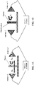
- FIGS. 1A and 1B A schematic depiction of the apparatus used to determine the dielectric properties of the materials of this disclosure using the Free Space Method for un-backed and metal-backed samples is shown in FIGS. 1A and 1B , respectively. Injection molded plaques of 6 inch x 8 inch x 1/8 inch dimensions are used for these Free Space dielectric measurements.
- Dielectric measurements using the Free Space Method can be performed in two different modes, the Transmission Mode and the Metal-backed Reflection Mode.
- the Transmission Mode of measurement allows the three types of radiation, namely Absorption into the sample, Reflection off the sample, and Transmission through the sample to be measured.
- the Metal-backed Reflection Mode of measurement on the other hand, a metallic plate (stainless steel, aluminum, etc.) is placed between the material under test and the receiving antenna so transmission through the sample is almost completely suppressed, and only microwave Absorption into the material and microwave Reflection off the material can be evaluated.
- the amount (in percent) of radiation absorbed by the material under test is calculated as the difference between the total energy impinging on the sample (or 100%) and the sum of the amount (in percent) of radiation transmitted through the sample (measured from S 21 , and reaching the receiving antenna) and reflected off the sample (measured from S 11 , and returning back to the emitting antenna).
- dielectric properties that radar designers consider when selecting materials for microwave radar interference applications.
- FIG. 2 shows a typical graph of the magnitude of the Scattering parameters (in dB) S 11 (for Reflection) and S 21 (for Transmission) of a carbon-based material used to absorb microwave radiation in the W-band at frequencies between 75 and 110 GHz.
- S 11 equal to zero dB indicates that the material shows no reflection loss (100% Reflecting), as it is the case of a metal plate made out of aluminum or stainless steel.
- S 21 equal to zero dB indicates that the material experiences no transmission loss (100% Transmitting), as it is the case for air.
- materials having a S 11 larger than 0 dB would be less than 100% reflecting (they would experience some loss in reflection), and materials having a S 21 larger than 0 dB would be less than 100% transmitting (they would experience some loss in transmission).
- the negative sign in the values of the S parameters indicates that energy has been lost, with larger negative numbers indicating larger losses.
- a S 11 equal to about -2.5 dB would indicate a Percent Reflected Power of 31.6%
- a S 21 equal to about -15 dB would correspond to a Percent Transmitted Power of 0.1%
- the Percent Absorbed Power would be equal to about 68.3%.
- Shielding Effectiveness (SE) of a material describes the ability of the material to reduce the electromagnetic radiation around it by blocking the field with barriers or shields made of conductive and/or magnetic components.
- the shielding can be effected by either absorbing or reflecting part or all of the electromagnetic radiation impinging on the material to be protected.
- the ability of the shielding material to block this harmful radiation usually depends on the frequency (or wavelength) of the incoming radiation, thickness of the protective layer, and it is expected to vary with the electrical conductivity and/or dielectric properties of the material.
- S 11 is the Scattering Parameter for Reflection
- S 21 is the Scattering Parameter for Transmission.
- SE T -10 log (
- Similar formulas can be used to calculate other dielectric properties, such as Attenuation, Reflection and Insertion Loss, Power Absorbed, and many others, in terms of the Scattering parameters. The formulas used to calculate the properties of the materials of this disclosure are provided below.
- ⁇ represents the Propagation Constant
- d is the thickness of the plaque.
- Suitable polyesters include, but are not limited to, polybutylene terephthalate (PBT), polyethylene terephthalate (PET), poly(cyclohexylenedimethylene terephthalate) (PCT), polyethylene terephthalate glycol (PETG), polycyclohexylene dimethylene terephthalate glycol (PCTG), polycyclohexylene dimethylene terephthalate acid (PCTA), polyethylene naphthalate (PEN), polybutylene naphthalate (PBN), copolymers thereof, or a combination thereof.
- PBT polybutylene terephthalate
- PET polyethylene terephthalate
- PCT poly(cyclohexylenedimethylene terephthalate)
- PCT polyethylene terephthalate glycol
- PCTG polycyclohexylene dimethylene terephthalate glycol
- PCTA polycyclohexylene dimethylene terephthalate acid
- PEN polyethylene naphthalate
- Suitable polyester components include, but are not limited to, polybutylene terephthalate (PBT), polyethylene terephthalate (PET), poly(cyclohexylenedimethylene terephthalate) (PCT), polyethylene terephthalate glycol (PETG), polycyclohexylene dimethylene terephthalate glycol (PCTG), polycyclohexylene dimethylene terephthalate acid (PCTA), copolymers thereof, or a combination thereof.
- PCT is a crystalline polyester formed from cyclohexanedimethanol (CHDM) and either dimethyl terephthalate (DMT) or terephthalic acid (TPA).
- PETG and PCTG are copolyesters formed by including ethylene glycol (EG) in the polymerization reaction.
- PETG is formed if less than 50% of the diol content in the copolyester is CHDM;
- PCTG is formed if greater than 50% of the diol content in the copolyester is CHDM.
- PCTA is formed by including additional diacids such as isophthalic acid (IPA).
- IPA isophthalic acid
- the polyester component includes PBT.
- the CNT filler may in some aspects have an average diameter of about 5-15 nanometers (nm), a surface area of at least 100 square meters per gram (m 2 /g), and/or a volume resistivity less than 10 -3 Ohm.centimeters ( ⁇ .cm).
- Exemplary CNTs are available from Nanocyl (e.g., NC7000 TM ).
- the CNT filler may be present in the composition in an amount of from about 0.01 wt% to about 1.95 wt%.
- the composition includes from 0.01 wt% to 1.9 wt%, or from 0.01 wt% to 1.8 wt%, or from 0.01 wt% to 1.7 wt%, or from 0.01 wt% to 1.6 wt%, or from 0.01 wt% to 1.5 wt%, or from 0.01 wt% to 1.4 wt%, or from 0.01 wt% to 1.3 wt%, or from 0.01 wt% to 1.2 wt%, or from 0.01 wt% to 1.1 wt%, or from 0.01 wt% to 1.0 wt%, or from 0.01 wt% to 0.9 wt%, or from 0.01 wt% to 0.8 wt%, or from 0.01 wt% to 0.7 wt%, or from 0.01 wt% to 0.6
- the composition includes at least one additional additive in some aspects.
- the at least one additional additive may include, but is not limited to, an acid scavenger, an anti-drip agent, an antioxidant, an antistatic agent, a chain extender, a colorant, a de-molding agent, a flow promoter, a lubricant, a mold release agent, a plasticizer, a quenching agent, a flame retardant, a UV reflecting additive, an impact modifier, a blowing agent, a reinforcing agent, or a combination thereof.
- the at least one additional additive may be included in the thermoplastic composition in any amount that will not significantly adversely affect the desired properties of the composition.
- the composition has a volume electrical resistivity of at least 10 11 ⁇ .cm. Volume electrical resistivity may be determined in accordance with ASTM D257. In further aspects the composition has a volume electrical resistivity of at least 10 12 ⁇ .cm, or at least 10 13 ⁇ .cm, or at least 10 14 ⁇ .cm, or from 10 11 ⁇ .cm to 10 15 ⁇ .cm.
- a molded sample of the composition has a percent Absorbed Power measured in Transmission mode of at least 60% when observed at frequencies of from 75 GHz to 110 GHz according to a Free Space method. In other aspects a molded sample of the composition has a percent Absorbed Power measured in Transmission mode of at least 61%, or at least 62%, or at least 63%, or at least 64%, or at least 65%, or at least 66%, or at least 67%, or at least 68%, or at least 69%, or at least 70%, or at least 71%, or at least 72%, or at least 73%, or at least 74%, or at least 75%, or from 60-85%, or from 65-85%, or from 65-80%, when observed at frequencies of from 75 GHz to 110 GHz according to a Free Space method.
- the composition includes from about 0.01 wt% to about 1 wt% of the CNT filler, and a molded sample of the composition has a Percent Absorbed Power measured in Transmission mode of at least 75% when observed at 77 GHz frequency according to a Free Space method.
- the one or any foregoing components described herein may be first dry blended with each other, or dry blended with any combination of foregoing components, then fed into an extruder from one or multi-feeders, or separately fed into an extruder from one or multi-feeders.
- the fillers used in the disclosure may also be first processed into a masterbatch, then fed into an extruder.
- the components may be fed into the extruder from a throat hopper or any side feeders.
- the extruders used in the disclosure may have a single screw, multiple screws, intermeshing co-rotating or counter rotating screws, non-intermeshing co-rotating or counter rotating screws, reciprocating screws, screws with pins, screws with screens, barrels with pins, rolls, rams, helical rotors, co-kneaders, disc-pack processors, various other types of extrusion equipment, or combinations including at least one of the foregoing.
- the components may also be mixed together and then melt-blended to form the thermoplastic compositions.
- the melt blending of the components involves the use of shear force, extensional force, compressive force, ultrasonic energy, electromagnetic energy, thermal energy or combinations including at least one of the foregoing forces or forms of energy.
- the barrel temperature on the extruder during compounding can be set at the temperature where at least a portion of the polymer has reached a temperature greater than or equal to about the melting temperature, if the resin is a semi-crystalline organic polymer, or the flow point (e.g., the glass transition temperature) if the resin is an amorphous resin.
- thermoplastic composition may first be extruded and formed into pellets. The pellets may then be fed into a molding machine where it may be formed into any desirable shape or product.
- thermoplastic composition emanating from a single melt blender may be formed into sheets or strands and subjected to post-extrusion processes such as annealing, uniaxial or biaxial orientation.
- the temperature of the melt in the present process may in some aspects be maintained as low as possible in order to avoid excessive thermal degradation of the components.
- the melt temperature is maintained between about 230°C and about 350°C, although higher temperatures can be used provided that the residence time of the resin in the processing equipment is kept relatively short.
- the melt processed composition exits processing equipment such as an extruder through small exit holes in a die.
- the resulting strands of molten resin may be cooled by passing the strands through a water bath.
- the cooled strands can be chopped into pellets for packaging and further handling.
- methods for forming a thermoplastic composition include: combining a thermoplastic polymer component including a polyester with from about 0.01 wt% to about 1.95 wt% of a carbon nanotube (CNT) filler to form a mixture; and molding the mixture to form the thermoplastic composition.
- a molded sample of the thermoplastic composition has a percent Absorbed Power measured in Transmission mode of at least 60% when observed at 77GHz frequency according to a Free Space method.
- the step of molding the mixture includes at least one of extruding, injection molding, rotational molding, blow molding or thermoforming the mixture to form the thermoplastic composition.
- the present disclosure pertains to shaped, formed, or molded articles including the thermoplastic compositions.
- the thermoplastic compositions can be molded into useful shaped articles by a variety of means such as injection molding, extrusion, rotational molding, blow molding and thermoforming to form articles and structural components of, for example, personal or commercial electronics devices, including but not limited to cellular telephones, tablet computers, personal computers, notebook and portable computers, and other such equipment, medical applications, RFID applications, automotive applications, and the like.
- the article is extrusion molded.
- the article is injection molded.
- the article is a microwave absorber for an internal or external radar sensor.
- the article is a microwave absorber for a radar sensor, camera, or an electronic control unit.
- the article includes a transmitting antenna, a receiving antenna, and at least two openings to allow transmission of microwave radiation between the transmitting antenna and the receiving antenna.
- the present disclosure pertains to and includes at least the following aspects.
- thermoplastic composition comprising:
- thermoplastic composition according to Aspect 1 wherein the polyester comprises polybutylene terephthalate (PBT), polyethylene terephthalate (PET), poly(cyclohexylenedimethylene terephthalate) (PCT), polyethylene terephthalate glycol (PETG), polycyclohexylene dimethylene terephthalate glycol (PCTG), polycyclohexylene dimethylene terephthalate acid (PCTA), polyethylene naphthalate (PEN), polybutylene naphthalate (PBN), copolymers thereof, or a combination thereof.
- PBT polybutylene terephthalate
- PET polyethylene terephthalate
- PCT poly(cyclohexylenedimethylene terephthalate)
- PCT polyethylene terephthalate glycol
- PCTG polycyclohexylene dimethylene terephthalate glycol
- PCTA polycyclohexylene dimethylene terephthalate acid
- PEN polyethylene naphthalate
- thermoplastic composition according to Aspect 1 or 2 wherein the composition comprises polybutylene terephthalate (PBT).
- PBT polybutylene terephthalate
- thermoplastic composition according to any of Aspects 1 to 3, wherein the CNT filler has an average diameter of about 5-15 nanometers (nm), a surface area of at least 100 square meters per gram (m 2 /g), and a volume resistivity less than 10 -3 Ohm.centimeters ( ⁇ .cm).
- thermoplastic composition according to any of Aspects 1 to 4, wherein the composition has a volume electrical resistivity of at least 10 11 ⁇ .cm.
- thermoplastic composition according to any of Aspects 1 to 5, wherein a molded sample of the composition has a percent Absorbed Power measured in Transmission mode of at least 65% when observed at frequencies of from 75 GHz to 110 GHz according to a Free Space method.
- thermoplastic composition according to any of Aspects 1 to 6, wherein the composition comprises from about 0.01 wt% to about 1 wt% of the CNT filler, wherein a molded sample of the composition has a Percent Absorbed Power measured in Transmission mode of at least 75% when observed at 77GHz frequency according to a Free Space method.
- thermoplastic composition according to any of Aspects 1 to 7, wherein the composition further comprises at least one additional additive.
- thermoplastic composition according to Aspect 8 wherein the at least one additional additive comprises an acid scavenger, an anti-drip agent, an antioxidant, an antistatic agent, a chain extender, a colorant, a de-molding agent, a flow promoter, a lubricant, a mold release agent, a plasticizer, a quenching agent, a flame retardant, a UV reflecting additive, an impact modifier, a blowing agent, a reinforcing agent, or a combination thereof.
- the at least one additional additive comprises an acid scavenger, an anti-drip agent, an antioxidant, an antistatic agent, a chain extender, a colorant, a de-molding agent, a flow promoter, a lubricant, a mold release agent, a plasticizer, a quenching agent, a flame retardant, a UV reflecting additive, an impact modifier, a blowing agent, a reinforcing agent, or a combination thereof.
- Aspect 10 An article comprising the thermoplastic composition.
- Aspect 11 The article according to Aspect 10, wherein the article is a microwave absorber for an internal or external radar sensor.
- Aspect 12 The article according to Aspect 10 or 11, wherein the article is a microwave absorber for a radar sensor, camera, or an electronic control unit.
- Aspect 13 The article according to any of Aspects 10 to 12, wherein the article comprises a transmitting antenna, a receiving antenna, and at least two openings to allow transmission of microwave radiation between the transmitting antenna and the receiving antenna.
- a method for forming a thermoplastic composition comprising:
- Aspect 15 The method according to Aspect 14, wherein molding the mixture comprises at least one of extruding, injection molding, rotational molding, blow molding or thermoforming the mixture to form the thermoplastic composition.
- reaction conditions e.g., component concentrations, desired solvents, solvent mixtures, temperatures, pressures and other reaction ranges and conditions that can be used to optimize the product purity and yield obtained from the described process. Only reasonable and routine experimentation will be required to optimize such process conditions.
- the PBT-MWCNT masterbatch used in the compositions described herein was diluted with different amounts of fresh, unfilled Ultradur ® B4500 (BASF), a medium-viscosity PBT grade suitable for use in manufacturing thin-walled profiles and pipes. This grade is also suitable for the manufacture of industrial functional parts in injection molding applications.
- the amount of masterbatch in the compositions varied from 20 to 5 weight percent, and the amount of fresh PBT resin was varied from 80 to 95 weight percent.
- These polymer/masterbatch ratios produced materials containing from about 3 weight % to about 0.75 weight % of carbon nanotubes in the final formulation.
- Example and comparative compositions were prepared and various properties determined as set forth in Table 1: Table 1 - Example and Comparative Compositions and Properties Composition CEx1 Ex1 Ex2 CEx2 CEx3 MB (Nanocyl MB) (wt%) 0 5 10 15 20 MWCNTs in MB (wt%) - 15 15 15 15 PBT in MB (wt%) - 85 85 85 85 85 85 85 85 85 Ultradur ® B4500 (PBT) (wt%) - 95 90 85 80 Total PBT (wt%) 100* 99.25 98.5 97.75 97 Total CNT (wt%) 0 0.75 1.5 2.25 3 Properties Frequency (Hz) 6.70E+10 7.70E+10 7.70E+10 7.70E+10 7.70E+10 7.70E+10 ⁇ ' 3.220 6.161 10.843 15.513 20.163 ⁇ " 0.0023 1.389 3.963 6.931 10.480 ⁇ "/ ⁇ ' (tan ⁇ ) 0.0007 0.225 0.365
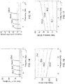
- FIGS. 3-23 Graphical illustrations of the data set forth above are provided in FIGS. 3-23 .
- FIG. 3 shows that the real and imaginary parts of the complex dielectric permittivity both increased with the CNT loading in the formulation.
- FIG. 4 shows the same trend for the dissipation factor ( ⁇ "/ ⁇ ') or tan ⁇ observed in these formulations.
- FIG. 5 shows that the Attenuation Constant increased from about -35 dB/cm to about -160 dB/cm, and
- FIG. 6 shows that the Total Shielding Effectiveness increased from about 12 dB to about 60 dB when the CNT loading in the formulation increased.
- FIG. 7 shows that the percent reflected power measured in transmission mode increased with the CNT loading, whereas the percent transmitted power and percent absorbed power measured in transmission mode both decreased when the CNT loading was increased.
- the Percent Reflected Power measured in Transmission mode increased from about 19% at 0.75wt% of nanotubes to about 46% at 3 wt% of nanotubes.
- the Percent Transmitted Power measured in Transmission mode decreased from about 4% at 0.75wt% of nanotubes to virtually non-measurable at a concentration of 3 wt% of nanotubes.
- the Percent Absorbed Power measured in Transmission mode decreased monotonically from about 77% at 0.75 wt% of nanotubes to about 54% at 3 wt% of nanotubes.
- FIG. 8 shows that the percent absorbed power at 77 GHz measured in both transmission mode and metal-backed reflection mode are similar for all the CNT loadings investigated. This result could be explained in terms of the low microwave transmission observed in these compositions, which would make the material under test behave almost as a metal plate located between the sample and the receiving antenna.
- FIGS. 9 and 10 show how the electrical surface and volume resistivities, respectively, decreased with the amount of CNT filler added to the formulation. It is also worth mentioning how a relatively small amount of CNT conductive filler renders these compositions virtually opaque (non-transmitting) to 77 GHz microwave radiation while only marginally affecting the electrical resistivity of the base polymer.
- FIGS. 12 and 13 show how the percent reflected power in transmission mode increased and the percent absorbed power in transmission mode decreased as the CNT loading increased rendering these compositions more electrically conductive (lower volume resistivities).
- FIGS. 14 and 15 show the real part and imaginary part, respectively, of the complex dielectric permittivity for the entire range of frequencies (75-110 GHz) in the W-band. As both graphs show, the complex permittivities of the compositions of this disclosure are virtually independent of frequency in the frequency range investigated.
- FIGS. 16 and 17 describe the attenuation constant and total shielding effectiveness, respectively, for the entire range (75-110 GHz) of frequencies investigated.
- FIGS. 18 and 19 show the percent absorbed power in transmission mode and metal-backed reflection mode, respectively, for the entire range (75-110 GHz) of frequencies investigated.
- FIGS. 20 , 21 , 22 and 23 show the percent absorbed, reflected and transmitted power measured in transmission mode for all frequencies of the W-band (75-110 GHz) of Ex1, Ex2, CEx2, and CEx3, respectively, described in this disclosure.
Landscapes
- Chemical & Material Sciences (AREA)
- Polymers & Plastics (AREA)
- Health & Medical Sciences (AREA)
- Chemical Kinetics & Catalysis (AREA)
- Medicinal Chemistry (AREA)
- Organic Chemistry (AREA)
- Engineering & Computer Science (AREA)
- Materials Engineering (AREA)
- Nanotechnology (AREA)
- Electromagnetism (AREA)
- Physics & Mathematics (AREA)
- Compositions Of Macromolecular Compounds (AREA)
- Aerials With Secondary Devices (AREA)
Abstract
Thermoplastic compositions include: a thermoplastic polymer component including a polyester; and from about 0.01 wt% to about 1.95 wt% of a carbon nanotube (CNT) filler. A molded sample of the composition has a percent Absorbed Power measured in Transmission mode of at least 60% when observed at 77GHz frequency according to a Free Space method. In some aspects the polyester includes polybutylene terephthalate (PBT). Further aspects include articles (e.g., a radar sensor, a camera, an electronic control unit, etc.) including a molded part including a microwave absorbing material (absorber). The article may have at least two openings to allow the transmission of microwave radiation between a transmitting antenna and a receiving antenna located in/on the printed circuit board of the sensor.
Description
- The present disclosure relates to thermoplastic compositions including a polyester and a carbon nanotube (CNT) filler suitable for use as microwave absorbers in sensor applications.
- The automotive industry is increasingly making use of electronic radar sensors to provide drivers assistance with features such as adaptive cruise control, parking/lane change assist, back-up warning, blind spot detection, collision avoidance, and many others. In order for these sensors to operate effectively, they need to be protected from spurious sources of electromagnetic radiation. Radar sensors for automotive include radome-type plastic components, which are mostly transparent to microwave radiation, and absorber-type plastic components, which trap microwave energy in a certain frequency range to protect the sensor from outside radiation interference. These plastics components are usually injection molded into the final part using relatively high injection pressures and melt temperatures. Microwave absorbing materials made from carbon black powder, graphite or carbon fibers usually require of relatively large quantities of the carbon filler to provide enough shielding interference in the K-band and W-band of the electromagnetic spectrum.
- Electronic radar sensors are used in the automotive industry to aid drivers in operations such as cruise control, lane change, self-parking, blind spot detection and many others. These sensors need to be protected from electromagnetic interference that can damage their normal operation. Metals (aluminum, stainless steel) are the most common materials used for microwave (MW) shielding, but they are heavy, expensive and demand of complex processing to be shaped into a final part.
- Polymer/carbon composites are preferred due to their low density, low cost, easy shaping, and manufacturability into high volume molded parts. Carbon fillers trap or deflect MW radiation in enclosure walls protecting the electronic sensors inside the cavity. Relatively high dielectric constant and electrical conductivity, and large dielectric and magnetic losses are some of the features required for materials used in microwave shielding.
- Microwave radiation (∼1-300 GHz frequency, ∼300-1 mm wavelength) is the most common source of EM energy used in the operation of radar sensors for automotive applications. Metals (e.g., aluminum and stainless steel), polymer composite materials containing metallic fillers, such as aluminum flakes, stainless steel fibers and silver-coated polyamide fibers, metalized coatings, inherently conductive polymers (polyacetylene, polypyrrole, polythiophene, polyaniline, etc.), silicon carbide, ferrites (Fe2O3+Ni/Zn/Cd/Co oxide), and carbonyl iron are some of the materials that are being used to shield automotive radar sensors from damaging microwave electromagnetic radiation.
- There are several dielectric properties that radar designers consider when selecting materials for microwave radar interference. Complex permittivity (real and imaginary parts), amount of radiation absorbed, reflected or transmitted by the material, shielding effectiveness, reflection loss and attenuation are only some of the material properties of interest for the manufacture of plastic components for radar sensor applications. Frequency of the incoming radiation and material thickness are also important when trapping microwave energy that if not eliminated or minimized can interfere with the normal operation of the automotive electronic sensors.
- Carbon (e.g., powder, platelets, fibers) is emerging as the filler of choice to impart electromagnetic interference properties to polymers, which when unfilled are virtually transparent to microwave radiation. When used in under-the-hood automotive enclosures, for example, polymer-carbon composites can protect the radar sensors located inside the enclosure by preventing the electromagnetic radiation from an outside or inside source to deteriorate the sensor's electronic performance.
- These and other shortcomings are addressed by aspects of the present disclosure.
- Aspects of the disclosure relate to thermoplastic compositions including: a thermoplastic polymer component including a polyester; and from about 0.01 wt% to about 1.95 wt% of a carbon nanotube (CNT) filler. A molded sample of the composition has a percent Absorbed Power measured in Transmission mode of at least 60% when observed at 77GHz frequency according to a Free Space method. In some aspects the polyester includes polybutylene terephthalate (PBT). Further aspects include articles (e.g., a radar sensor, a camera, an electronic control unit, etc.) including a molded part including a microwave absorbing material (absorber). The article may have at least two openings to allow the transmission of microwave radiation between a transmitting antenna and a receiving antenna located in/on the printed circuit board of the sensor.
- In yet further aspects the disclosure relates to methods for forming a thermoplastic composition, including: combining a thermoplastic polymer component including a polyester with from about 0.01 wt% to about 1.95 wt% of a carbon nanotube (CNT) filler to form a mixture; and molding the mixture to form the thermoplastic composition. A molded sample of the thermoplastic composition has a percent Absorbed Power measured in Transmission mode of at least 60% when observed at 77GHz frequency according to a Free Space method.
- In the drawings, which are not necessarily drawn to scale, like numerals may describe similar components in different views. Like numerals having different letter suffixes may represent different instances of similar components. The drawings illustrate generally, by way of example, but not by way of limitation, various aspects discussed in the present document.
-
FIGS. 1A and 1B are schematic depictions of the apparatus used to determine the dielectric properties of the materials of this disclosure using the Free Space Method for un-backed and metal-backed samples, respectively. -
FIG. 2 shows a typical graph of the magnitude of the Scattering parameters (in dB) S11 (for Reflection) and S21 (for Transmission) of a carbon-based material used to absorb microwave radiation in the W-band at frequencies between 75 and 110 GHz. -
FIG. 3 is a graph illustrating permittivity (real and imaginary parts) as a function of CNT loading observed at a 77 GHz frequency for example and comparative compositions according to aspects of the disclosure. -
FIG. 4 is a graph illustrating dissipation factor (Df), or tan δ, as a function of CNT loading observed at a 77 GHz frequency for example and comparative compositions according to aspects of the disclosure. -
FIG. 5 is a graph illustrating attenuation constant as a function of CNT loading observed at a 77 GHz frequency for example and comparative compositions according to aspects of the disclosure. -
FIG. 6 is a graph illustrating total shielding effectiveness as a function of CNT loading observed at 77 GHz frequency for example and comparative compositions according to aspects of the disclosure. -
FIG. 7 is a graph illustrating percent power in transmission mode as a function of CNT loading observed at 77 GHz frequency for example and comparative compositions according to aspects of the disclosure. -
FIG. 8 is a graph illustrating percent absorbed power in Transmission and Metal-backed Reflection modes as a function of CNT loading for example and comparative compositions according to aspects of the disclosure. -
FIG. 9 is a graph illustrating surface resistivity as a function of CNT loading for example and comparative compositions according to aspects of the disclosure. -
FIG. 10 is a graph illustrating volume resistivity as a function of CNT loading for example and comparative compositions according to aspects of the disclosure. -
FIG. 11 is a graph illustrating surface and volume resistivities as a function of CNT loading for example and comparative compositions according to aspects of the disclosure. -
FIG. 12 is a graph illustrating percent reflected power in transmission mode observed at 77 GHz frequency as a function of volume electrical resistivity for example and comparative compositions according to aspects of the disclosure. -
FIG. 13 is a graph illustrating percent absorbed power in transmission mode observed at 77 GHz frequency as a function of volume electrical resistivity for example and comparative compositions according to aspects of the disclosure. -
FIG. 14 is a graph illustrating the real part of the complex dielectric permittivity as a function of frequency in the W-band (75-110 GHz) for example and comparative compositions according to aspects of the disclosure. -
FIG. 15 is a graph illustrating the imaginary part of the complex dielectric permittivity as a function of frequency in the W-band (75-110 GHz) for example and comparative compositions according to aspects of the disclosure. -
FIG. 16 is a graph illustrating attenuation as a function of frequency in the W-band (75-110 GHz) for example and comparative compositions according to aspects of the disclosure. -
FIG. 17 is a graph illustrating total shielding effectiveness as a function of frequency in the W-band (75-110 GHz) for example and comparative compositions according to aspects of the disclosure. -
FIG. 18 is a graph illustrating percent absorbed power measured in transmission mode as a function of frequency in the W-band (75-110 GHz) for example and comparative compositions according to aspects of the disclosure. -
FIG. 19 is a graph illustrating percent absorbed power measured in metal-backed reflection mode as a function of frequency in the W-band (75-110 GHz) for example and comparative compositions according to aspects of the disclosure. -
FIG. 20 is a graph illustrating absorbed, reflected and transmitted power as a function of frequency in the W-band (75-110 GHz) for example composition Ex1 according to aspects of the disclosure. -
FIG. 21 is a graph illustrating absorbed, reflected and transmitted power as a function of frequency in the W-band (75-110 GHz) for example composition Ex2 according to aspects of the disclosure. -
FIG. 22 is a graph illustrating absorbed, reflected and transmitted power as a function of frequency in the W-band (75-110 GHz) for comparative composition CEx2. -
FIG. 23 is a graph illustrating absorbed, reflected and transmitted power as a function of frequency in the W-band (75-110 GHz) for comparative composition CEx3. - This present disclosure describes plastic composite materials including relatively low levels of multi-wall carbon nanotubes that can be used to manufacture microwave absorbers for sensors such as automotive radar sensors, and that can be injection molded using conventional molding processes.
- Carbon nanotubes are preferred over carbon powder, graphite or carbon fibers since they provide adequate microwave interference performance at relatively low loadings. Lower loadings of carbon, for example, would result in improvements to the ductility, impact strength, surface aesthetics, and flow of these materials under high shear rate conditions.
- Another aspect of the disclosure is a component of an automotive radar sensor (plate, enclosure, cover, etc.), which is molded from a material including a polymer and carbon nanotubes as a microwave absorbing filler, with the molded part having certain design, average thickness, microwave absorption efficiency, absorption bandwidth, shielding effectiveness, attenuation and electrical surface and volume resistivity properties.
- Further aspects of the disclosure include articles (e.g., a radar sensor, a camera, an electronic control unit, etc.) including a molded part including a microwave absorbing material (absorber). The article may have at least two openings to allow the transmission of microwave radiation between a transmitting antenna and a receiving antenna located in/on the printed circuit board of the sensor.
- The present disclosure can be understood more readily by reference to the following detailed description of the disclosure and the Examples included therein. In various aspects, the present disclosure relates to thermoplastic compositions including: a thermoplastic polymer component including a polyester; and from about 0.01 wt% to about 1.95 wt% of a carbon nanotube (CNT) filler. A molded sample of the composition has a percent Absorbed Power measured in Transmission mode of at least 60% when observed at 77GHz frequency according to a Free Space method.
- Before the present compounds, compositions, articles, systems, devices, and/or methods are disclosed and described, it is to be understood that they are not limited to specific synthetic methods unless otherwise specified, or to particular reagents unless otherwise specified, as such can, of course, vary. It is also to be understood that the terminology used herein is for the purpose of describing particular aspects only and is not intended to be limiting.
- Various combinations of elements of this disclosure are encompassed by this disclosure, e.g., combinations of elements from dependent claims that depend upon the same independent claim.
- Moreover, it is to be understood that unless otherwise expressly stated, it is in no way intended that any method set forth herein be construed as requiring that its steps be performed in a specific order. Accordingly, where a method claim does not actually recite an order to be followed by its steps or it is not otherwise specifically stated in the claims or descriptions that the steps are to be limited to a specific order, it is in no way intended that an order be inferred, in any respect. This holds for any possible non-express basis for interpretation, including: matters of logic with respect to arrangement of steps or operational flow; plain meaning derived from grammatical organization or punctuation; and the number or type of aspects described in the specification.
- All publications mentioned herein are incorporated herein by reference to disclose and describe the methods and/or materials in connection with which the publications are cited.
- It is also to be understood that the terminology used herein is for the purpose of describing particular aspects only and is not intended to be limiting. As used in the specification and in the claims, the term "comprising" can include the aspects "consisting of' and "consisting essentially of." Unless defined otherwise, all technical and scientific terms used herein have the same meaning as commonly understood by one of ordinary skill in the art to which this disclosure belongs. In this specification and in the claims which follow, reference will be made to a number of terms which shall be defined herein.
- As used in the specification and the appended claims, the singular forms "a," "an" and "the" include plural referents unless the context clearly dictates otherwise. Thus, for example, reference to "a polyester" includes mixtures of two or more polyester polymers.
- As used herein, the term "combination" is inclusive of blends, mixtures, alloys, reaction products, and the like.
- Ranges can be expressed herein as from one value (first value) to another value (second value). When such a range is expressed, the range includes in some aspects one or both of the first value and the second value. Similarly, when values are expressed as approximations, by use of the antecedent 'about,' it will be understood that the particular value forms another aspect. It will be further understood that the endpoints of each of the ranges are significant both in relation to the other endpoint, and independently of the other endpoint. It is also understood that there are a number of values disclosed herein, and that each value is also herein disclosed as "about" that particular value in addition to the value itself. For example, if the value "10" is disclosed, then "about 10" is also disclosed. It is also understood that each unit between two particular units are also disclosed. For example, if 10 and 15 are disclosed, then 11, 12, 13, and 14 are also disclosed.
- As used herein, the terms "about" and "at or about" mean that the amount or value in question can be the designated value, approximately the designated value, or about the same as the designated value. It is generally understood, as used herein, that it is the nominal value indicated ±10% variation unless otherwise indicated or inferred. The term is intended to convey that similar values promote equivalent results or effects recited in the claims. That is, it is understood that amounts, sizes, formulations, parameters, and other quantities and characteristics are not and need not be exact, but can be approximate and/or larger or smaller, as desired, reflecting tolerances, conversion factors, rounding off, measurement error and the like, and other factors known to those of skill in the art. In general, an amount, size, formulation, parameter or other quantity or characteristic is "about" or "approximate" whether or not expressly stated to be such. It is understood that where "about" is used before a quantitative value, the parameter also includes the specific quantitative value itself, unless specifically stated otherwise.
- Disclosed are the components to be used to prepare the compositions of the disclosure as well as the compositions themselves to be used within the methods disclosed herein. These and other materials are disclosed herein, and it is understood that when combinations, subsets, interactions, groups, etc. of these materials are disclosed that while specific reference of each various individual and collective combinations and permutation of these compounds cannot be explicitly disclosed, each is specifically contemplated and described herein. For example, if a particular compound is disclosed and discussed and a number of modifications that can be made to a number of molecules including the compounds are discussed, specifically contemplated is each and every combination and permutation of the compound and the modifications that are possible unless specifically indicated to the contrary. Thus, if a class of molecules A, B, and C are disclosed as well as a class of molecules D, E, and F and an example of a combination molecule, A-D is disclosed, then even if each is not individually recited each is individually and collectively contemplated meaning combinations, A-E, A-F, B-D, B-E, B-F, C-D, C-E, and C-F are considered disclosed. Likewise, any subset or combination of these is also disclosed. Thus, for example, the sub-group of A-E, B-F, and C-E would be considered disclosed. This concept applies to all aspects of this application including, but not limited to, steps in methods of making and using the compositions of the disclosure. Thus, if there are a variety of additional steps that can be performed it is understood that each of these additional steps can be performed with any specific aspect or combination of aspects of the methods of the disclosure.
- References in the specification and concluding claims to parts by weight of a particular element or component in a composition or article, denotes the weight relationship between the element or component and any other elements or components in the composition or article for which a part by weight is expressed. Thus, in a compound containing 2 parts by weight of component X and 5 parts by weight component Y, X and Y are present at a weight ratio of 2:5, and are present in such ratio regardless of whether additional components are contained in the compound.
- A weight percent of a component, unless specifically stated to the contrary, is based on the total weight of the formulation or composition in which the component is included.
- The terms "residues" and "structural units", used in reference to the constituents of the polymers, are synonymous throughout the specification.
- As used herein the terms "weight percent," "wt%," and "wt. %," which can be used interchangeably, indicate the percent by weight of a given component based on the total weight of the composition, unless otherwise specified. That is, unless otherwise specified, all wt% values are based on the total weight of the composition. It should be understood that the sum of wt% values for all components in a disclosed composition or formulation are equal to 100.
- Unless otherwise stated to the contrary herein, all test standards are the most recent standard in effect at the time of filing this application.
- Each of the materials disclosed herein are either commercially available and/or the methods for the production thereof are known to those of skill in the art.
- It is understood that the compositions disclosed herein have certain functions. Disclosed herein are certain structural requirements for performing the disclosed functions and it is understood that there are a variety of structures that can perform the same function that are related to the disclosed structures, and that these structures will typically achieve the same result.
- In some aspects a polyester (e.g., polybutylene terephthalate (PBT)) masterbatch including a fixed loading of multi wall carbon nanotubes (CNT), is combined with fresh, unfilled polyester resin to dilute the original masterbatch to form blends of varying concentrations of nanotubes. The carbon nanotubes impart electrical conductivity and microwave absorbing properties to the composition. One masterbatch composition suitable for use in aspects of the disclosure is PLASTICYL™ PBT1501 (available from NANOCYL), which is a multiwall carbon nanotube (MWCNT) PBT masterbatch containing 15 percent by weight of nanotubes. NANOCYL® nanotubes are thin, multi-wall carbon nanotubes produced via a catalytic chemical vapor deposition (CCVD) process. The carbon nanotubes are tube-shaped materials that are exclusively composed of carbon atoms having a nanometer size diameter. The graphite layers can be visualized somewhat like a rolled-up chicken wire with a continuous unbroken hexagonal mesh and carbon atoms at the apexes of the hexagons. From action of van der Waals forces, carbon nanotubes have a tendency to cluster into bundles or agglomerates. Consequently, carbon nanotubes look like a black powder. At nanoscale, however, they have a spaghetti-like structure.
- One advantage of carbon nanotubes is that compositions including them have improved mechanical properties as compared to other conductive fillers such as carbon black or graphite due to their high aspect ratio resulting in a relatively low amount of nanotubes needed to reach a specific electrical conductivity. Nanotubes typically increase the viscosity more than carbon black at equal loading, but much lower quantities of nanotubes are required for processing in most cases. Other benefits of CNTs include: high electrical conductivity; good processability; retention of mechanical properties; high recyclability in thermoplastics; and good thermal dissipation properties (among several others). Specific properties of NANOCYL's NC7000™ CNTs include:
Specific characterization of MC7000™ PROPERTIES UNIT VALUE METHOD OF MEASUREMENT Average diameter 10-9m 9.5 Transmission Electron Microscopy (TEM) Average length µm 1.5 Transmission Electron Microscopy (TEM) Carbon purity % 90 Thermogravimetric analysis (TGA) Transition Metal oxide % < 1% Inductively Coupled Plasma Mass Spectrometry (ICP-MS) Amorphous carbon - * High resolution Transmission Electron Microscopy (HRTEM) Surface Area m2/g 250-300 BET surface area analysis Volume resistivity Ω.cm 10-4 Internal test method (resistivity on powder) *Pyrotyticalty deposited carbon on the surface of the NC7000 - In specific aspects the disclosure relates to thermoplastic compositions including: a thermoplastic polymer component including a polyester; and from about 0.01 wt% to about 1.95 wt% of a carbon nanotube (CNT) filler. A molded sample of the composition has a percent Absorbed Power measured in Transmission mode of at least 60% when observed at 77 GHz frequency according to a Free Space method. As used herein, a "molded sample" refers to a 6 inch x 8 inch x 1/8 inch injection molded sample of the composition.
- The Free Space Method used to measure the dielectric properties of the compositions of this disclosure includes a vector network analyzer, two antennae facing each other with a sample holder placed equidistant between them. The fundamental experimental quantities produced by the Free Space Method are the so-called Scattering parameters, or S-parameters, which are used to describe the input-output relationship between the different ports of an electric network in terms of amplitude and phase versus frequencies. The S-parameters are usually identified by a two-number subscript, with the first number in the subscript referring to the responding port, while the second number refers to the incident port. Thus, S21 means the response at
port 2 due to a signal atport 1. The Scattering parameters are complex numbers having a real part and an imaginary part, and they describe the amount of microwave radiation that is either reflected off the sample or transmitted through the sample. The Scattering parameter S11 for Reflection, for example, represents a signal that originates inantenna 1 and that is received back at the same antenna after impinging on the sample and is reflected off. Similarly, the Scattering parameter S21 for Transmission represents a signal that originates inantenna 1 and is received byantenna 2 after being transmitted through the material under test. Scattering parameters for Reflection and Transmission that represent a signal that originates atantenna 2, S22 for Reflection and S12 for Transmission, can also be defined. The S-parameter matrix can be used to determine reflection coefficients and transmission gains from both sides of a two-port network for which four S-parameters, S11, S22, S21, and S12, as defined before, can be identified. A software is then used to convert the Scattering parameter output of the network analyzer to dielectric properties. Free-space measurement techniques provide a method for determining the dielectric permittivity and magnetic permeability of the magneto-dielectric material under test. These methods are contactless, that is the material under test does not make direct contact with any active component of the equipment involved in the measurement. - A schematic depiction of the apparatus used to determine the dielectric properties of the materials of this disclosure using the Free Space Method for un-backed and metal-backed samples is shown in
FIGS. 1A and 1B , respectively. Injection molded plaques of 6 inch x 8 inch x 1/8 inch dimensions are used for these Free Space dielectric measurements. - Dielectric measurements using the Free Space Method can be performed in two different modes, the Transmission Mode and the Metal-backed Reflection Mode. The Transmission Mode of measurement allows the three types of radiation, namely Absorption into the sample, Reflection off the sample, and Transmission through the sample to be measured. In the Metal-backed Reflection Mode of measurement, on the other hand, a metallic plate (stainless steel, aluminum, etc.) is placed between the material under test and the receiving antenna so transmission through the sample is almost completely suppressed, and only microwave Absorption into the material and microwave Reflection off the material can be evaluated. Since the combination of the two antennae in Transmission mode can only measure the Scattering parameter for Reflection, S11, and the Scattering parameter for Transmission, S21, the amount (in percent) of radiation absorbed by the material under test is calculated as the difference between the total energy impinging on the sample (or 100%) and the sum of the amount (in percent) of radiation transmitted through the sample (measured from S21, and reaching the receiving antenna) and reflected off the sample (measured from S11, and returning back to the emitting antenna). In many applications, it is desirable to maximize percent Absorbed power, and to minimize percent Reflected power and percent Transmitted power when measurements are made using the Transmission mode. There are several dielectric properties that radar designers consider when selecting materials for microwave radar interference applications. Complex permittivity (real and imaginary parts), amount of radiation Absorbed, Reflected or Transmitted by the material, Shielding Effectiveness, Reflection Loss, and Attenuation are only some of the material properties of interest for the manufacture of plastic components for radar sensor applications. Frequency of the incoming radiation and material thickness are also important when trapping microwave energy that if not eliminated or minimized would interfere with the normal operation of the automotive electronic sensors.
-
FIG. 2 shows a typical graph of the magnitude of the Scattering parameters (in dB) S11 (for Reflection) and S21 (for Transmission) of a carbon-based material used to absorb microwave radiation in the W-band at frequencies between 75 and 110 GHz. In this graph, S11 equal to zero dB indicates that the material shows no reflection loss (100% Reflecting), as it is the case of a metal plate made out of aluminum or stainless steel. Similarly, S21 equal to zero dB indicates that the material experiences no transmission loss (100% Transmitting), as it is the case for air. In this context, materials having a S11 larger than 0 dB would be less than 100% reflecting (they would experience some loss in reflection), and materials having a S21 larger than 0 dB would be less than 100% transmitting (they would experience some loss in transmission). The negative sign in the values of the S parameters indicates that energy has been lost, with larger negative numbers indicating larger losses. As the graph shows for 77 GHz of frequency, a S11 equal to about -2.5 dB would indicate a Percent Reflected Power of 31.6%, a S21 equal to about -15 dB would correspond to a Percent Transmitted Power of 0.1%, and by difference to 100% the Percent Absorbed Power would be equal to about 68.3%. - In its most generic definition, Shielding Effectiveness (SE) of a material describes the ability of the material to reduce the electromagnetic radiation around it by blocking the field with barriers or shields made of conductive and/or magnetic components. In these cases, the shielding can be effected by either absorbing or reflecting part or all of the electromagnetic radiation impinging on the material to be protected. The ability of the shielding material to block this harmful radiation usually depends on the frequency (or wavelength) of the incoming radiation, thickness of the protective layer, and it is expected to vary with the electrical conductivity and/or dielectric properties of the material. The total Shielding Effectiveness of a material is the result of its reflection, absorption, and internal reflection losses, and it is represented by the following equation:

- For total shielding efficiencies larger than 10 dB, the shielding effectiveness due to multiple reflections SEM is usually negligible. Therefore, the Total Shielding Effectiveness is reduced to:

- SEA and SER are calculated directly from S-parameters measurements using a vector network analyzer as follows:


- In the above equations, S11 is the Scattering Parameter for Reflection, and S21 is the Scattering Parameter for Transmission. If we replace the above expressions for SER and SEA into the equation for SET, the Total Shielding Effectiveness can be written as SET = -10 log (|S21|2), which is analogous to the expressions for Transmission Loss or Insertion loss. Similar formulas can be used to calculate other dielectric properties, such as Attenuation, Reflection and Insertion Loss, Power Absorbed, and many others, in terms of the Scattering parameters. The formulas used to calculate the properties of the materials of this disclosure are provided below.
- Reflection and Transmission Coefficients :
- * Equation of the Reflection Coefficient:

- In the equation above,

- * Equation of the Transmission Coefficient:

- Complex Relative Dielectric Permittivity:


- Loss Tangent:

- Propagation Constant: γ = α + jβ, where, γ is calculated using the extracted Complex Permittivity and Complex Permeability as:
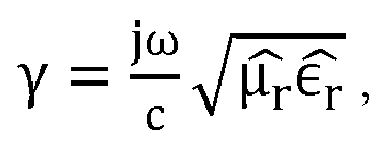
- The Attenuation Constant, α, causes a signal amplitude to decrease along a transmission path, and it is calculated as α = Real (γ) (Np/m, or Nepers/m), and then plotted in dB/cm using:

- Return Loss (RL) and Insertion Loss (IL):


- Calculated S11 and S21 Parameters [60]: The Reflection and Transmission Coefficients are calculated using the extracted Permittivity and Permeability as:


- Percent Power: Since microwave Absorption cannot be measured directly, only Reflection (from S11) and Transmission (from S21), the Percent Absorbed Power can be calculated from:


- Scattering Parameter for Reflection in Metal-backed Reflection Mode: S11 is calculated using the Transmission Line model:


- For simple one-layer absorber with metal backing the equation for reflection is:

- Suitable polyesters include, but are not limited to, polybutylene terephthalate (PBT), polyethylene terephthalate (PET), poly(cyclohexylenedimethylene terephthalate) (PCT), polyethylene terephthalate glycol (PETG), polycyclohexylene dimethylene terephthalate glycol (PCTG), polycyclohexylene dimethylene terephthalate acid (PCTA), polyethylene naphthalate (PEN), polybutylene naphthalate (PBN), copolymers thereof, or a combination thereof. Suitable polyester components include, but are not limited to, polybutylene terephthalate (PBT), polyethylene terephthalate (PET), poly(cyclohexylenedimethylene terephthalate) (PCT), polyethylene terephthalate glycol (PETG), polycyclohexylene dimethylene terephthalate glycol (PCTG), polycyclohexylene dimethylene terephthalate acid (PCTA), copolymers thereof, or a combination thereof. PCT is a crystalline polyester formed from cyclohexanedimethanol (CHDM) and either dimethyl terephthalate (DMT) or terephthalic acid (TPA). PETG and PCTG are copolyesters formed by including ethylene glycol (EG) in the polymerization reaction. PETG is formed if less than 50% of the diol content in the copolyester is CHDM; PCTG is formed if greater than 50% of the diol content in the copolyester is CHDM. PCTA is formed by including additional diacids such as isophthalic acid (IPA). In a particular aspect the polyester component includes PBT.
- The CNT filler may in some aspects have an average diameter of about 5-15 nanometers (nm), a surface area of at least 100 square meters per gram (m2/g), and/or a volume resistivity less than 10-3 Ohm.centimeters (Ω.cm). Exemplary CNTs are available from Nanocyl (e.g., NC7000™).
- The CNT filler may be present in the composition in an amount of from about 0.01 wt% to about 1.95 wt%. In some aspects the composition includes from 0.01 wt% to 1.9 wt%, or from 0.01 wt% to 1.8 wt%, or from 0.01 wt% to 1.7 wt%, or from 0.01 wt% to 1.6 wt%, or from 0.01 wt% to 1.5 wt%, or from 0.01 wt% to 1.4 wt%, or from 0.01 wt% to 1.3 wt%, or from 0.01 wt% to 1.2 wt%, or from 0.01 wt% to 1.1 wt%, or from 0.01 wt% to 1.0 wt%, or from 0.01 wt% to 0.9 wt%, or from 0.01 wt% to 0.8 wt%, or from 0.01 wt% to 0.7 wt%, or from 0.01 wt% to 0.6 wt%, or from 0.01 wt% to 0.5 wt%.
- The composition includes at least one additional additive in some aspects. The at least one additional additive may include, but is not limited to, an acid scavenger, an anti-drip agent, an antioxidant, an antistatic agent, a chain extender, a colorant, a de-molding agent, a flow promoter, a lubricant, a mold release agent, a plasticizer, a quenching agent, a flame retardant, a UV reflecting additive, an impact modifier, a blowing agent, a reinforcing agent, or a combination thereof. The at least one additional additive may be included in the thermoplastic composition in any amount that will not significantly adversely affect the desired properties of the composition.
- In certain aspects the composition has a volume electrical resistivity of at least 1011 Ω.cm. Volume electrical resistivity may be determined in accordance with ASTM D257. In further aspects the composition has a volume electrical resistivity of at least 1012 Ω.cm, or at least 1013 Ω.cm, or at least 1014 Ω.cm, or from 1011 Ω.cm to 1015 Ω.cm.
- In some aspects a molded sample of the composition has a percent Absorbed Power measured in Transmission mode of at least 60% when observed at frequencies of from 75 GHz to 110 GHz according to a Free Space method. In other aspects a molded sample of the composition has a percent Absorbed Power measured in Transmission mode of at least 61%, or at least 62%, or at least 63%, or at least 64%, or at least 65%, or at least 66%, or at least 67%, or at least 68%, or at least 69%, or at least 70%, or at least 71%, or at least 72%, or at least 73%, or at least 74%, or at least 75%, or from 60-85%, or from 65-85%, or from 65-80%, when observed at frequencies of from 75 GHz to 110 GHz according to a Free Space method.
- In a specific aspect the composition includes from about 0.01 wt% to about 1 wt% of the CNT filler, and a molded sample of the composition has a Percent Absorbed Power measured in Transmission mode of at least 75% when observed at 77 GHz frequency according to a Free Space method.
- The one or any foregoing components described herein may be first dry blended with each other, or dry blended with any combination of foregoing components, then fed into an extruder from one or multi-feeders, or separately fed into an extruder from one or multi-feeders. The fillers used in the disclosure may also be first processed into a masterbatch, then fed into an extruder. The components may be fed into the extruder from a throat hopper or any side feeders.
- The extruders used in the disclosure may have a single screw, multiple screws, intermeshing co-rotating or counter rotating screws, non-intermeshing co-rotating or counter rotating screws, reciprocating screws, screws with pins, screws with screens, barrels with pins, rolls, rams, helical rotors, co-kneaders, disc-pack processors, various other types of extrusion equipment, or combinations including at least one of the foregoing.
- The components may also be mixed together and then melt-blended to form the thermoplastic compositions. The melt blending of the components involves the use of shear force, extensional force, compressive force, ultrasonic energy, electromagnetic energy, thermal energy or combinations including at least one of the foregoing forces or forms of energy.
- The barrel temperature on the extruder during compounding can be set at the temperature where at least a portion of the polymer has reached a temperature greater than or equal to about the melting temperature, if the resin is a semi-crystalline organic polymer, or the flow point (e.g., the glass transition temperature) if the resin is an amorphous resin.
- The mixture including the foregoing mentioned components may be subject to multiple blending and forming steps if desirable. For example, the thermoplastic composition may first be extruded and formed into pellets. The pellets may then be fed into a molding machine where it may be formed into any desirable shape or product. Alternatively, the thermoplastic composition emanating from a single melt blender may be formed into sheets or strands and subjected to post-extrusion processes such as annealing, uniaxial or biaxial orientation.
- The temperature of the melt in the present process may in some aspects be maintained as low as possible in order to avoid excessive thermal degradation of the components. In certain aspects the melt temperature is maintained between about 230°C and about 350°C, although higher temperatures can be used provided that the residence time of the resin in the processing equipment is kept relatively short. In some aspects the melt processed composition exits processing equipment such as an extruder through small exit holes in a die. The resulting strands of molten resin may be cooled by passing the strands through a water bath. The cooled strands can be chopped into pellets for packaging and further handling.
- In some aspects methods for forming a thermoplastic composition include: combining a thermoplastic polymer component including a polyester with from about 0.01 wt% to about 1.95 wt% of a carbon nanotube (CNT) filler to form a mixture; and molding the mixture to form the thermoplastic composition. A molded sample of the thermoplastic composition has a percent Absorbed Power measured in Transmission mode of at least 60% when observed at 77GHz frequency according to a Free Space method. In further aspects the step of molding the mixture includes at least one of extruding, injection molding, rotational molding, blow molding or thermoforming the mixture to form the thermoplastic composition.
- In certain aspects, the present disclosure pertains to shaped, formed, or molded articles including the thermoplastic compositions. The thermoplastic compositions can be molded into useful shaped articles by a variety of means such as injection molding, extrusion, rotational molding, blow molding and thermoforming to form articles and structural components of, for example, personal or commercial electronics devices, including but not limited to cellular telephones, tablet computers, personal computers, notebook and portable computers, and other such equipment, medical applications, RFID applications, automotive applications, and the like. In a further aspect, the article is extrusion molded. In a still further aspect, the article is injection molded. In specific aspects the article is a microwave absorber for an internal or external radar sensor. In yet further aspects the article is a microwave absorber for a radar sensor, camera, or an electronic control unit. In certain aspects the article includes a transmitting antenna, a receiving antenna, and at least two openings to allow transmission of microwave radiation between the transmitting antenna and the receiving antenna.
- Various combinations of elements of this disclosure are encompassed by this disclosure, e.g., combinations of elements from dependent claims that depend upon the same independent claim.
- In various aspects, the present disclosure pertains to and includes at least the following aspects.
-
Aspect 1. A thermoplastic composition comprising: - a thermoplastic polymer component comprising a polyester; and
- from about 0.01 wt% to about 1.95 wt% of a carbon nanotube (CNT) filler,
-
Aspect 2. The thermoplastic composition according toAspect 1, wherein the polyester comprises polybutylene terephthalate (PBT), polyethylene terephthalate (PET), poly(cyclohexylenedimethylene terephthalate) (PCT), polyethylene terephthalate glycol (PETG), polycyclohexylene dimethylene terephthalate glycol (PCTG), polycyclohexylene dimethylene terephthalate acid (PCTA), polyethylene naphthalate (PEN), polybutylene naphthalate (PBN), copolymers thereof, or a combination thereof. -
Aspect 3. The thermoplastic composition according toAspect - Aspect 4. The thermoplastic composition according to any of
Aspects 1 to 3, wherein the CNT filler has an average diameter of about 5-15 nanometers (nm), a surface area of at least 100 square meters per gram (m2/g), and a volume resistivity less than 10-3 Ohm.centimeters (Ω.cm). -
Aspect 5. The thermoplastic composition according to any ofAspects 1 to 4, wherein the composition has a volume electrical resistivity of at least 1011 Ω.cm. - Aspect 6. The thermoplastic composition according to any of
Aspects 1 to 5, wherein a molded sample of the composition has a percent Absorbed Power measured in Transmission mode of at least 65% when observed at frequencies of from 75 GHz to 110 GHz according to a Free Space method. - Aspect 7. The thermoplastic composition according to any of
Aspects 1 to 6, wherein the composition comprises from about 0.01 wt% to about 1 wt% of the CNT filler, wherein a molded sample of the composition has a Percent Absorbed Power measured in Transmission mode of at least 75% when observed at 77GHz frequency according to a Free Space method. -
Aspect 8. The thermoplastic composition according to any ofAspects 1 to 7, wherein the composition further comprises at least one additional additive. -
Aspect 9. The thermoplastic composition according toAspect 8, wherein the at least one additional additive comprises an acid scavenger, an anti-drip agent, an antioxidant, an antistatic agent, a chain extender, a colorant, a de-molding agent, a flow promoter, a lubricant, a mold release agent, a plasticizer, a quenching agent, a flame retardant, a UV reflecting additive, an impact modifier, a blowing agent, a reinforcing agent, or a combination thereof. -
Aspect 10. An article comprising the thermoplastic composition. -
Aspect 11. The article according toAspect 10, wherein the article is a microwave absorber for an internal or external radar sensor. -
Aspect 12. The article according toAspect - Aspect 13. The article according to any of
Aspects 10 to 12, wherein the article comprises a transmitting antenna, a receiving antenna, and at least two openings to allow transmission of microwave radiation between the transmitting antenna and the receiving antenna. -
Aspect 14. A method for forming a thermoplastic composition, comprising: - combining a thermoplastic polymer component comprising a polyester with from about 0.01 wt% to about 1.95 wt% of a carbon nanotube (CNT) filler to form a mixture; and
- molding the mixture to form the thermoplastic composition,
-
Aspect 15. The method according toAspect 14, wherein molding the mixture comprises at least one of extruding, injection molding, rotational molding, blow molding or thermoforming the mixture to form the thermoplastic composition. - The following examples are put forth so as to provide those of ordinary skill in the art with a complete disclosure and description of how the compounds, compositions, articles, devices and/or methods claimed herein are made and evaluated, and are intended to be purely exemplary and are not intended to limit the disclosure. Efforts have been made to ensure accuracy with respect to numbers (e.g., amounts, temperature, etc.), but some errors and deviations should be accounted for. Unless indicated otherwise, parts are parts by weight, temperature is in °C or is at ambient temperature, and pressure is at or near atmospheric. Unless indicated otherwise, percentages referring to composition are in terms of wt%.
- There are numerous variations and combinations of reaction conditions, e.g., component concentrations, desired solvents, solvent mixtures, temperatures, pressures and other reaction ranges and conditions that can be used to optimize the product purity and yield obtained from the described process. Only reasonable and routine experimentation will be required to optimize such process conditions.
- The PBT-MWCNT masterbatch used in the compositions described herein was diluted with different amounts of fresh, unfilled Ultradur® B4500 (BASF), a medium-viscosity PBT grade suitable for use in manufacturing thin-walled profiles and pipes. This grade is also suitable for the manufacture of industrial functional parts in injection molding applications. The amount of masterbatch in the compositions varied from 20 to 5 weight percent, and the amount of fresh PBT resin was varied from 80 to 95 weight percent. These polymer/masterbatch ratios produced materials containing from about 3 weight % to about 0.75 weight % of carbon nanotubes in the final formulation. Example and comparative compositions were prepared and various properties determined as set forth in Table 1:
Table 1 - Example and Comparative Compositions and Properties Composition CEx1 Ex1 Ex2 CEx2 CEx3 MB (Nanocyl MB) (wt%) 0 5 10 15 20 MWCNTs in MB (wt%) - 15 15 15 15 PBT in MB (wt%) - 85 85 85 85 Ultradur® B4500 (PBT) (wt%) - 95 90 85 80 Total PBT (wt%) 100* 99.25 98.5 97.75 97 Total CNT (wt%) 0 0.75 1.5 2.25 3 Properties Frequency (Hz) 6.70E+10 7.70E+10 7.70E+10 7.70E+10 7.70E+10 ε' 3.220 6.161 10.843 15.513 20.163 ε" 0.0023 1.389 3.963 6.931 10.480 ε"/ ε' (tan δ) 0.0007 0.225 0.365 0.447 0.520 Attenuation Constant (dB/cm) -38.941 -82.948 -120.404 -158.480 Total Shielding Effectiveness (dB) 13.860 28.776 41.287 53.865 RL Measured (Metal-Backed, Frontside) (dB) -5.857 -4.682 -3.954 -3.395 RL Calculated (Metal-Backed) (dB) -6.338 -5.176 -4.191 -3.581 % Power in Metal-Backed Reflection (Absorption) 74.04 65.98 59.77 54.24 % Power in Transmission (Reflected) 27.52 19.23 34.30 40.37 45.76 % Power in Transmission (Absorbed) 0.41 76.66 65.57 59.62 54.24 % Power in Transmission (Transmitted) 72.07 4.11 0.13 0.01 0.00 Surface Resistivity (Ohm/sq) (Avg) 8.53E+13 4.74E+13 5.33E+10 3.72E+06 Volume Resistivity (Ohm.cm) (Avg) 7.13E+14 1.12E+14 5.52E+10 7.11E+07 * PBT in CEx1 was Valox 325 - Graphical illustrations of the data set forth above are provided in
FIGS. 3-23 . -
FIG. 3 shows that the real and imaginary parts of the complex dielectric permittivity both increased with the CNT loading in the formulation.FIG. 4 shows the same trend for the dissipation factor (ε"/ε') or tan δ observed in these formulations.FIG. 5 shows that the Attenuation Constant increased from about -35 dB/cm to about -160 dB/cm, andFIG. 6 shows that the Total Shielding Effectiveness increased from about 12 dB to about 60 dB when the CNT loading in the formulation increased.FIG. 7 shows that the percent reflected power measured in transmission mode increased with the CNT loading, whereas the percent transmitted power and percent absorbed power measured in transmission mode both decreased when the CNT loading was increased. As these results show for a frequency of 77GHz, the Percent Reflected Power measured in Transmission mode increased from about 19% at 0.75wt% of nanotubes to about 46% at 3 wt% of nanotubes. Similarly, the Percent Transmitted Power measured in Transmission mode decreased from about 4% at 0.75wt% of nanotubes to virtually non-measurable at a concentration of 3 wt% of nanotubes. The Percent Absorbed Power measured in Transmission mode decreased monotonically from about 77% at 0.75 wt% of nanotubes to about 54% at 3 wt% of nanotubes. These results may be explained in terms of the electrical resistivities observed for these materials, as the increase in the amount of conductive filler would render these materials more electrically conductive thus behaving dielectrically more like metals, which are less absorbing, less transmitting and more reflecting of microwave radiation when compared with polymer-based materials. -
FIG. 8 shows that the percent absorbed power at 77 GHz measured in both transmission mode and metal-backed reflection mode are similar for all the CNT loadings investigated. This result could be explained in terms of the low microwave transmission observed in these compositions, which would make the material under test behave almost as a metal plate located between the sample and the receiving antenna.FIGS. 9 and 10 show how the electrical surface and volume resistivities, respectively, decreased with the amount of CNT filler added to the formulation. It is also worth mentioning how a relatively small amount of CNT conductive filler renders these compositions virtually opaque (non-transmitting) to 77 GHz microwave radiation while only marginally affecting the electrical resistivity of the base polymer.FIG. 11 shows a back-to-back comparison of the surface and volume electrical resistivities of the compositions of this disclosure in terms of CNT loading. The similar results observed for both electrical resistivities suggest that a relatively uniform distribution of the conductive fibrils in the polymeric matrix has been obtained in the compounding step to prepare these materials.FIGS. 12 and 13 show how the percent reflected power in transmission mode increased and the percent absorbed power in transmission mode decreased as the CNT loading increased rendering these compositions more electrically conductive (lower volume resistivities). -
FIGS. 14 and 15 show the real part and imaginary part, respectively, of the complex dielectric permittivity for the entire range of frequencies (75-110 GHz) in the W-band. As both graphs show, the complex permittivities of the compositions of this disclosure are virtually independent of frequency in the frequency range investigated.FIGS. 16 and 17 describe the attenuation constant and total shielding effectiveness, respectively, for the entire range (75-110 GHz) of frequencies investigated.FIGS. 18 and 19 show the percent absorbed power in transmission mode and metal-backed reflection mode, respectively, for the entire range (75-110 GHz) of frequencies investigated.FIGS. 20 ,21 ,22 and23 show the percent absorbed, reflected and transmitted power measured in transmission mode for all frequencies of the W-band (75-110 GHz) of Ex1, Ex2, CEx2, and CEx3, respectively, described in this disclosure. - From measurements of ε' and ε" observed at 67 GHz on a 3.132 mm thick plaque of pure VALOX/PBT with no filler, the calculated Percent Transmitted Power, Percent Reflected Power, and Percent Absorbed Power of the pure resin at 67 GHz were 72%, 27.5% and 0.4%, respectively. From these results, it can be speculated that the highest Percent Absorbed Power measured in Transmission mode of the example compositions of this disclosure will occur either at 0.75 wt% of carbon nanotubes, or less. The most suitable compositions absorb 77GHz microwave radiation of 60% or higher, or even more suitably 65% or higher.
- The above description is intended to be illustrative, and not restrictive. For example, the above-described examples (or one or more aspects thereof) may be used in combination with each other. Other aspects can be used, such as by one of ordinary skill in the art upon reviewing the above description. The Abstract is provided to comply with 37 C.F.R. §1.72(b), to allow the reader to quickly ascertain the nature of the technical disclosure. It is submitted with the understanding that it will not be used to interpret or limit the scope or meaning of the claims. Also, in the above Detailed Description, various features may be grouped together to streamline the disclosure. This should not be interpreted as intending that an unclaimed disclosed feature is essential to any claim. Rather, inventive subject matter may lie in less than all features of a particular disclosed aspect. Thus, the following claims are hereby incorporated into the Detailed Description as examples or aspects, with each claim standing on its own as a separate aspect, and it is contemplated that such aspects can be combined with each other in various combinations or permutations. The scope of the disclosure should be determined with reference to the appended claims, along with the full scope of equivalents to which such claims are entitled.
Claims (15)
- A thermoplastic composition comprising:a thermoplastic polymer component comprising a polyester; andfrom about 0.01 wt% to about 1.95 wt% of a carbon nanotube (CNT) filler,wherein a molded sample of the composition has a percent Absorbed Power measured in Transmission mode of at least 60% when observed at 77GHz frequency according to a Free Space method.
- The thermoplastic composition according to claim 1, wherein the polyester comprises polybutylene terephthalate (PBT), polyethylene terephthalate (PET), poly(cyclohexylenedimethylene terephthalate) (PCT), polyethylene terephthalate glycol (PETG), polycyclohexylene dimethylene terephthalate glycol (PCTG), polycyclohexylene dimethylene terephthalate acid (PCTA), polyethylene naphthalate (PEN), polybutylene naphthalate (PBN), copolymers thereof, or a combination thereof.
- The thermoplastic composition according to claim 1 or 2, wherein the composition comprises polybutylene terephthalate (PBT).
- The thermoplastic composition according to any of claims 1 to 3, wherein the CNT filler has an average diameter of about 5-15 nanometers (nm), a surface area of at least 100 square meters per gram (m2/g), and a volume resistivity less than 10-3 Ohm.centimeters (Ω.cm).
- The thermoplastic composition according to any of claims 1 to 4, wherein the composition has a volume electrical resistivity of at least 1011 Ω.cm.
- The thermoplastic composition according to any of claims 1 to 5, wherein a molded sample of the composition has a percent Absorbed Power measured in Transmission mode of at least 65% when observed at frequencies of from 75 GHz to 110 GHz according to a Free Space method.
- The thermoplastic composition according to any of claims 1 to 6, wherein the composition comprises from about 0.01 wt% to about 1 wt% of the CNT filler, wherein a molded sample of the composition has a Percent Absorbed Power measured in Transmission mode of at least 75% when observed at 77GHz frequency according to a Free Space method.
- The thermoplastic composition according to any of claims 1 to 7, wherein the composition further comprises at least one additional additive.
- The thermoplastic composition according to claim 8, wherein the at least one additional additive comprises an acid scavenger, an anti-drip agent, an antioxidant, an antistatic agent, a chain extender, a colorant, a de-molding agent, a flow promoter, a lubricant, a mold release agent, a plasticizer, a quenching agent, a flame retardant, a UV reflecting additive, an impact modifier, a blowing agent, a reinforcing agent, or a combination thereof.
- An article comprising the thermoplastic composition.
- The article according to claim 10, wherein the article is a microwave absorber for an internal or external radar sensor.
- The article according to claim 10 or 11, wherein the article is a microwave absorber for a radar sensor, camera, or an electronic control unit.
- The article according to any of claims 10 to 12, wherein the article comprises a transmitting antenna, a receiving antenna, and at least two openings to allow transmission of microwave radiation between the transmitting antenna and the receiving antenna.
- A method for forming a thermoplastic composition, comprising:combining a thermoplastic polymer component comprising a polyester with from about 0.01 wt% to about 1.95 wt% of a carbon nanotube (CNT) filler to form a mixture; andmolding the mixture to form the thermoplastic composition,wherein a molded sample of the thermoplastic composition has a percent Absorbed Power measured in Transmission mode of at least 60% when observed at 77GHz frequency according to a Free Space method.
- The method according to claim 14, wherein molding the mixture comprises at least one of extruding, injection molding, rotational molding, blow molding or thermoforming the mixture to form the thermoplastic composition.
Priority Applications (7)
| Application Number | Priority Date | Filing Date | Title |
|---|---|---|---|
| EP21184608.4A EP4116365A1 (en) | 2021-07-08 | 2021-07-08 | Polyester compositions including carbon nanotubes as microwave absorbers in sensor applications |
| US18/576,778 US12590200B2 (en) | 2021-07-08 | 2022-07-07 | Polyester compositions including carbon nanotubes as microwave absorbers in sensor applications |
| KR1020247003677A KR20240028478A (en) | 2021-07-08 | 2022-07-07 | Polyester compositions containing carbon nanotubes as microwave absorbers in sensor applications |
| EP22741003.2A EP4367176A1 (en) | 2021-07-08 | 2022-07-07 | Polyester compositions including carbon nanotubes as microwave absorbers in sensor applications |
| PCT/IB2022/056288 WO2023281440A1 (en) | 2021-07-08 | 2022-07-07 | Polyester compositions including carbon nanotubes as microwave absorbers in sensor applications |
| CN202280059003.5A CN117916298A (en) | 2021-07-08 | 2022-07-07 | Polyester compositions containing carbon nanotubes as microwave absorbers in sensor applications |
| JP2024500127A JP7776609B2 (en) | 2021-07-08 | 2022-07-07 | Polyester compositions containing carbon nanotubes as microwave absorbers in sensor applications |
Applications Claiming Priority (1)
| Application Number | Priority Date | Filing Date | Title |
|---|---|---|---|
| EP21184608.4A EP4116365A1 (en) | 2021-07-08 | 2021-07-08 | Polyester compositions including carbon nanotubes as microwave absorbers in sensor applications |
Publications (1)
| Publication Number | Publication Date |
|---|---|
| EP4116365A1 true EP4116365A1 (en) | 2023-01-11 |
Family
ID=76845140
Family Applications (2)
| Application Number | Title | Priority Date | Filing Date |
|---|---|---|---|
| EP21184608.4A Withdrawn EP4116365A1 (en) | 2021-07-08 | 2021-07-08 | Polyester compositions including carbon nanotubes as microwave absorbers in sensor applications |
| EP22741003.2A Pending EP4367176A1 (en) | 2021-07-08 | 2022-07-07 | Polyester compositions including carbon nanotubes as microwave absorbers in sensor applications |
Family Applications After (1)
| Application Number | Title | Priority Date | Filing Date |
|---|---|---|---|
| EP22741003.2A Pending EP4367176A1 (en) | 2021-07-08 | 2022-07-07 | Polyester compositions including carbon nanotubes as microwave absorbers in sensor applications |
Country Status (6)
| Country | Link |
|---|---|
| US (1) | US12590200B2 (en) |
| EP (2) | EP4116365A1 (en) |
| JP (1) | JP7776609B2 (en) |
| KR (1) | KR20240028478A (en) |
| CN (1) | CN117916298A (en) |
| WO (1) | WO2023281440A1 (en) |
Cited By (1)
| Publication number | Priority date | Publication date | Assignee | Title |
|---|---|---|---|---|
| EP4686738A1 (en) * | 2024-07-31 | 2026-02-04 | SHPP Global Technologies B.V. | Polyamide compositions including a carbon-based filler for microwave absorbers in automotive radar sensor adas applications |
Families Citing this family (1)
| Publication number | Priority date | Publication date | Assignee | Title |
|---|---|---|---|---|
| JP7790136B2 (en) * | 2021-12-16 | 2025-12-23 | 三菱ケミカル株式会社 | Resin composition, pellets, molded body, electromagnetic wave absorber, and method for producing resin composition |
Citations (2)
| Publication number | Priority date | Publication date | Assignee | Title |
|---|---|---|---|---|
| US20100143714A1 (en) * | 2008-12-08 | 2010-06-10 | Taiwan Textile Research Institute | Conductive masterbatches and conductive monofilaments |
| EP3845587A1 (en) * | 2019-12-31 | 2021-07-07 | SHPP Global Technologies B.V. | Microwave absorbing materials and molded articles for automotive radar sensor applications |
Family Cites Families (9)
| Publication number | Priority date | Publication date | Assignee | Title |
|---|---|---|---|---|
| JP2003100147A (en) | 2001-09-25 | 2003-04-04 | Nagase & Co Ltd | Conductive material containing carbon nanotube and its manufacturing method |
| EP2895534B1 (en) | 2013-08-01 | 2016-04-13 | Total Research & Technology Feluy | Masterbatches for preparing a composite materials with enhanced conductivity properties, process and composite materials produced |
| EP2902443B1 (en) | 2013-12-06 | 2018-10-10 | LG Chem, Ltd. | Thermoplastic resin composition for radar cover |
| JP2016108524A (en) | 2014-12-04 | 2016-06-20 | 東洋インキScホールディングス株式会社 | Conductive resin composition, conductive master batch, molded body, and production method of the same |
| JP6707859B2 (en) | 2015-12-25 | 2020-06-10 | 日本ゼオン株式会社 | Electromagnetic wave absorbing material |
| KR102136601B1 (en) | 2018-07-23 | 2020-07-24 | 주식회사 에스아이티 | Method of Manufacturing Carbonnanotube Pellet and Carbonnanotube Pellet Manufactured there by |
| CN115700024A (en) | 2020-06-17 | 2023-02-03 | 三菱工程塑料株式会社 | Resin composition and electromagnetic wave absorber |
| JP2022008176A (en) | 2020-06-17 | 2022-01-13 | 三菱エンジニアリングプラスチックス株式会社 | Resin composition and electromagnetic wave absorber |
| EP3943535A1 (en) | 2020-07-20 | 2022-01-26 | SHPP Global Technologies B.V. | Composites having improved microwave shielding properties |
-
2021
- 2021-07-08 EP EP21184608.4A patent/EP4116365A1/en not_active Withdrawn
-
2022
- 2022-07-07 WO PCT/IB2022/056288 patent/WO2023281440A1/en not_active Ceased
- 2022-07-07 JP JP2024500127A patent/JP7776609B2/en active Active
- 2022-07-07 KR KR1020247003677A patent/KR20240028478A/en active Pending
- 2022-07-07 CN CN202280059003.5A patent/CN117916298A/en active Pending
- 2022-07-07 EP EP22741003.2A patent/EP4367176A1/en active Pending
- 2022-07-07 US US18/576,778 patent/US12590200B2/en active Active
Patent Citations (2)
| Publication number | Priority date | Publication date | Assignee | Title |
|---|---|---|---|---|
| US20100143714A1 (en) * | 2008-12-08 | 2010-06-10 | Taiwan Textile Research Institute | Conductive masterbatches and conductive monofilaments |
| EP3845587A1 (en) * | 2019-12-31 | 2021-07-07 | SHPP Global Technologies B.V. | Microwave absorbing materials and molded articles for automotive radar sensor applications |
Non-Patent Citations (2)
| Title |
|---|
| SENG LEE YENG ET AL: "EMI shielding based on MWCNTs/polyester composites", APPLIED PHYSICS A, SPRINGER BERLIN HEIDELBERG, BERLIN/HEIDELBERG, vol. 124, no. 2, 15 January 2018 (2018-01-15), XP036975267, ISSN: 0947-8396, [retrieved on 20180115], DOI: 10.1007/S00339-018-1564-Y * |
| YIN HUAJIE ET AL: "Carbon-based nanofillers/Poly(butylene terephthalate): thermal, dielectric, electrical and rheological properties", JOURNAL OF POLYMER RESEARCH, SPRINGER NETHERLANDS, DORDRECHT, vol. 22, no. 7, 23 June 2015 (2015-06-23), pages 1 - 13, XP035522640, ISSN: 1022-9760, [retrieved on 20150623], DOI: 10.1007/S10965-015-0785-4 * |
Cited By (2)
| Publication number | Priority date | Publication date | Assignee | Title |
|---|---|---|---|---|
| EP4686738A1 (en) * | 2024-07-31 | 2026-02-04 | SHPP Global Technologies B.V. | Polyamide compositions including a carbon-based filler for microwave absorbers in automotive radar sensor adas applications |
| WO2026028132A1 (en) * | 2024-07-31 | 2026-02-05 | Shpp Global Technologies B.V. | Polyamide compositions including a carbon-based filler for microwave absorbers in automotive radar sensor adas applications |
Also Published As
| Publication number | Publication date |
|---|---|
| CN117916298A (en) | 2024-04-19 |
| US20250066578A1 (en) | 2025-02-27 |
| US12590200B2 (en) | 2026-03-31 |
| EP4367176A1 (en) | 2024-05-15 |
| KR20240028478A (en) | 2024-03-05 |
| JP7776609B2 (en) | 2025-11-26 |
| WO2023281440A1 (en) | 2023-01-12 |
| JP2024525540A (en) | 2024-07-12 |
Similar Documents
| Publication | Publication Date | Title |
|---|---|---|
| Katheria et al. | A journey of thermoplastic elastomer nanocomposites for electromagnetic shielding applications: from bench to transitional research | |
| US12590200B2 (en) | Polyester compositions including carbon nanotubes as microwave absorbers in sensor applications | |
| CN116171303B (en) | Composites with improved microwave shielding properties | |
| WO2020148653A1 (en) | Thermoplastic compositions having low dielectric constant | |
| US20240093004A1 (en) | PBT-Carbon Fiber Composites for Microwave Shielding | |
| Farukh et al. | Sandwich composites of polyurethane reinforced with poly (3, 4-ethylene dioxythiophene)-coated multiwalled carbon nanotubes with exceptional electromagnetic interference shielding properties | |
| EP4393988A1 (en) | Polypropylene compositions with enhanced microwave absorption and reduced microwave reflection | |
| EP4686738A1 (en) | Polyamide compositions including a carbon-based filler for microwave absorbers in automotive radar sensor adas applications | |
| US20240417530A1 (en) | Polycarbonate Compositions Including Carbon Nanotubes (CNTs) as Microwave Absorbers in Automotive Radar Sensor Applications | |
| US12319813B2 (en) | Electrically conductive microwave shielding compositions | |
| EP4209552A1 (en) | Articles and structures of wave absorption material | |
| EP4265674A1 (en) | Highly electrically conductive compounds for high temperature battery electrode plates | |
| EP4506409A1 (en) | Highly electrically conductive compounds containing hdpe and carbon nanotubes for battery electrode plates | |
| US20250122356A1 (en) | Thermoplastic Compositions Including Low Dielectric Carbon Black as a Signal Transmission Component | |
| iPolycond Consortium | Introduction to conductive polymer composites | |
| CN121712839A (en) | High conductivity compounds containing HDPE and carbon nanotubes for battery electrode plates |
Legal Events
| Date | Code | Title | Description |
|---|---|---|---|
| PUAI | Public reference made under article 153(3) epc to a published international application that has entered the european phase |
Free format text: ORIGINAL CODE: 0009012 |
|
| STAA | Information on the status of an ep patent application or granted ep patent |
Free format text: STATUS: THE APPLICATION HAS BEEN PUBLISHED |
|
| AK | Designated contracting states |
Kind code of ref document: A1 Designated state(s): AL AT BE BG CH CY CZ DE DK EE ES FI FR GB GR HR HU IE IS IT LI LT LU LV MC MK MT NL NO PL PT RO RS SE SI SK SM TR |
|
| STAA | Information on the status of an ep patent application or granted ep patent |
Free format text: STATUS: THE APPLICATION IS DEEMED TO BE WITHDRAWN |
|
| 18D | Application deemed to be withdrawn |
Effective date: 20230712 |