EP4116269A2 - Additive manufacture of optical components - Google Patents
Additive manufacture of optical components Download PDFInfo
- Publication number
- EP4116269A2 EP4116269A2 EP22168003.6A EP22168003A EP4116269A2 EP 4116269 A2 EP4116269 A2 EP 4116269A2 EP 22168003 A EP22168003 A EP 22168003A EP 4116269 A2 EP4116269 A2 EP 4116269A2
- Authority
- EP
- European Patent Office
- Prior art keywords
- core material
- glass
- facesheet
- glass powder
- layer
- Prior art date
- Legal status (The legal status is an assumption and is not a legal conclusion. Google has not performed a legal analysis and makes no representation as to the accuracy of the status listed.)
- Pending
Links
Images


Classifications
-
- C—CHEMISTRY; METALLURGY
- C03—GLASS; MINERAL OR SLAG WOOL
- C03B—MANUFACTURE, SHAPING, OR SUPPLEMENTARY PROCESSES
- C03B19/00—Other methods of shaping glass
- C03B19/01—Other methods of shaping glass by progressive fusion or sintering of powdered glass onto a shaping substrate, i.e. accretion, e.g. plasma oxidation deposition
-
- B—PERFORMING OPERATIONS; TRANSPORTING
- B33—ADDITIVE MANUFACTURING TECHNOLOGY
- B33Y—ADDITIVE MANUFACTURING, i.e. MANUFACTURING OF THREE-DIMENSIONAL [3D] OBJECTS BY ADDITIVE DEPOSITION, ADDITIVE AGGLOMERATION OR ADDITIVE LAYERING, e.g. BY 3D PRINTING, STEREOLITHOGRAPHY OR SELECTIVE LASER SINTERING
- B33Y10/00—Processes of additive manufacturing
-
- B—PERFORMING OPERATIONS; TRANSPORTING
- B33—ADDITIVE MANUFACTURING TECHNOLOGY
- B33Y—ADDITIVE MANUFACTURING, i.e. MANUFACTURING OF THREE-DIMENSIONAL [3D] OBJECTS BY ADDITIVE DEPOSITION, ADDITIVE AGGLOMERATION OR ADDITIVE LAYERING, e.g. BY 3D PRINTING, STEREOLITHOGRAPHY OR SELECTIVE LASER SINTERING
- B33Y80/00—Products made by additive manufacturing
-
- C—CHEMISTRY; METALLURGY
- C03—GLASS; MINERAL OR SLAG WOOL
- C03B—MANUFACTURE, SHAPING, OR SUPPLEMENTARY PROCESSES
- C03B19/00—Other methods of shaping glass
- C03B19/06—Other methods of shaping glass by sintering, e.g. by cold isostatic pressing of powders and subsequent sintering, by hot pressing of powders, by sintering slurries or dispersions not undergoing a liquid phase reaction
-
- C—CHEMISTRY; METALLURGY
- C03—GLASS; MINERAL OR SLAG WOOL
- C03C—CHEMICAL COMPOSITION OF GLASSES, GLAZES OR VITREOUS ENAMELS; SURFACE TREATMENT OF GLASS; SURFACE TREATMENT OF FIBRES OR FILAMENTS MADE FROM GLASS, MINERALS OR SLAGS; JOINING GLASS TO GLASS OR OTHER MATERIALS
- C03C17/00—Surface treatment of glass, not in the form of fibres or filaments, by coating
- C03C17/02—Surface treatment of glass, not in the form of fibres or filaments, by coating with glass
- C03C17/04—Surface treatment of glass, not in the form of fibres or filaments, by coating with glass by fritting glass powder
-
- C—CHEMISTRY; METALLURGY
- C03—GLASS; MINERAL OR SLAG WOOL
- C03C—CHEMICAL COMPOSITION OF GLASSES, GLAZES OR VITREOUS ENAMELS; SURFACE TREATMENT OF GLASS; SURFACE TREATMENT OF FIBRES OR FILAMENTS MADE FROM GLASS, MINERALS OR SLAGS; JOINING GLASS TO GLASS OR OTHER MATERIALS
- C03C17/00—Surface treatment of glass, not in the form of fibres or filaments, by coating
- C03C17/34—Surface treatment of glass, not in the form of fibres or filaments, by coating with at least two coatings having different compositions
- C03C17/3411—Surface treatment of glass, not in the form of fibres or filaments, by coating with at least two coatings having different compositions with at least two coatings of inorganic materials
- C03C17/3417—Surface treatment of glass, not in the form of fibres or filaments, by coating with at least two coatings having different compositions with at least two coatings of inorganic materials all coatings being oxide coatings
-
- C—CHEMISTRY; METALLURGY
- C03—GLASS; MINERAL OR SLAG WOOL
- C03C—CHEMICAL COMPOSITION OF GLASSES, GLAZES OR VITREOUS ENAMELS; SURFACE TREATMENT OF GLASS; SURFACE TREATMENT OF FIBRES OR FILAMENTS MADE FROM GLASS, MINERALS OR SLAGS; JOINING GLASS TO GLASS OR OTHER MATERIALS
- C03C23/00—Other surface treatment of glass not in the form of fibres or filaments
- C03C23/0005—Other surface treatment of glass not in the form of fibres or filaments by irradiation
- C03C23/0025—Other surface treatment of glass not in the form of fibres or filaments by irradiation by a laser beam
-
- C—CHEMISTRY; METALLURGY
- C03—GLASS; MINERAL OR SLAG WOOL
- C03C—CHEMICAL COMPOSITION OF GLASSES, GLAZES OR VITREOUS ENAMELS; SURFACE TREATMENT OF GLASS; SURFACE TREATMENT OF FIBRES OR FILAMENTS MADE FROM GLASS, MINERALS OR SLAGS; JOINING GLASS TO GLASS OR OTHER MATERIALS
- C03C3/00—Glass compositions
- C03C3/04—Glass compositions containing silica
- C03C3/062—Glass compositions containing silica with less than 40% silica by weight
- C03C3/064—Glass compositions containing silica with less than 40% silica by weight containing boron
- C03C3/066—Glass compositions containing silica with less than 40% silica by weight containing boron containing zinc
-
- C—CHEMISTRY; METALLURGY
- C03—GLASS; MINERAL OR SLAG WOOL
- C03C—CHEMICAL COMPOSITION OF GLASSES, GLAZES OR VITREOUS ENAMELS; SURFACE TREATMENT OF GLASS; SURFACE TREATMENT OF FIBRES OR FILAMENTS MADE FROM GLASS, MINERALS OR SLAGS; JOINING GLASS TO GLASS OR OTHER MATERIALS
- C03C3/00—Glass compositions
- C03C3/04—Glass compositions containing silica
- C03C3/076—Glass compositions containing silica with 40% to 90% silica, by weight
- C03C3/083—Glass compositions containing silica with 40% to 90% silica, by weight containing aluminium oxide or an iron compound
- C03C3/085—Glass compositions containing silica with 40% to 90% silica, by weight containing aluminium oxide or an iron compound containing an oxide of a divalent metal
- C03C3/087—Glass compositions containing silica with 40% to 90% silica, by weight containing aluminium oxide or an iron compound containing an oxide of a divalent metal containing calcium oxide, e.g. common sheet or container glass
-
- C—CHEMISTRY; METALLURGY
- C03—GLASS; MINERAL OR SLAG WOOL
- C03C—CHEMICAL COMPOSITION OF GLASSES, GLAZES OR VITREOUS ENAMELS; SURFACE TREATMENT OF GLASS; SURFACE TREATMENT OF FIBRES OR FILAMENTS MADE FROM GLASS, MINERALS OR SLAGS; JOINING GLASS TO GLASS OR OTHER MATERIALS
- C03C3/00—Glass compositions
- C03C3/04—Glass compositions containing silica
- C03C3/076—Glass compositions containing silica with 40% to 90% silica, by weight
- C03C3/097—Glass compositions containing silica with 40% to 90% silica, by weight containing phosphorus, niobium or tantalum
-
- C—CHEMISTRY; METALLURGY
- C03—GLASS; MINERAL OR SLAG WOOL
- C03C—CHEMICAL COMPOSITION OF GLASSES, GLAZES OR VITREOUS ENAMELS; SURFACE TREATMENT OF GLASS; SURFACE TREATMENT OF FIBRES OR FILAMENTS MADE FROM GLASS, MINERALS OR SLAGS; JOINING GLASS TO GLASS OR OTHER MATERIALS
- C03C8/00—Enamels; Glazes; Fusion seal compositions being frit compositions having non-frit additions
- C03C8/02—Frit compositions, i.e. in a powdered or comminuted form
-
- G—PHYSICS
- G02—OPTICS
- G02B—OPTICAL ELEMENTS, SYSTEMS OR APPARATUS
- G02B5/00—Optical elements other than lenses
- G02B5/08—Mirrors
- G02B5/10—Mirrors with curved faces
-
- C—CHEMISTRY; METALLURGY
- C03—GLASS; MINERAL OR SLAG WOOL
- C03B—MANUFACTURE, SHAPING, OR SUPPLEMENTARY PROCESSES
- C03B2201/00—Type of glass produced
- C03B2201/06—Doped silica-based glasses
- C03B2201/30—Doped silica-based glasses doped with metals, e.g. Ga, Sn, Sb, Pb or Bi
- C03B2201/40—Doped silica-based glasses doped with metals, e.g. Ga, Sn, Sb, Pb or Bi doped with transition metals other than rare earth metals, e.g. Zr, Nb, Ta or Zn
- C03B2201/42—Doped silica-based glasses doped with metals, e.g. Ga, Sn, Sb, Pb or Bi doped with transition metals other than rare earth metals, e.g. Zr, Nb, Ta or Zn doped with titanium
-
- C—CHEMISTRY; METALLURGY
- C03—GLASS; MINERAL OR SLAG WOOL
- C03C—CHEMICAL COMPOSITION OF GLASSES, GLAZES OR VITREOUS ENAMELS; SURFACE TREATMENT OF GLASS; SURFACE TREATMENT OF FIBRES OR FILAMENTS MADE FROM GLASS, MINERALS OR SLAGS; JOINING GLASS TO GLASS OR OTHER MATERIALS
- C03C2218/00—Methods for coating glass
- C03C2218/30—Aspects of methods for coating glass not covered above
- C03C2218/32—After-treatment
-
- C—CHEMISTRY; METALLURGY
- C03—GLASS; MINERAL OR SLAG WOOL
- C03C—CHEMICAL COMPOSITION OF GLASSES, GLAZES OR VITREOUS ENAMELS; SURFACE TREATMENT OF GLASS; SURFACE TREATMENT OF FIBRES OR FILAMENTS MADE FROM GLASS, MINERALS OR SLAGS; JOINING GLASS TO GLASS OR OTHER MATERIALS
- C03C2218/00—Methods for coating glass
- C03C2218/30—Aspects of methods for coating glass not covered above
- C03C2218/35—Exuding
Definitions
- the present disclosure relates to optics and additive manufacturing, and more particularly to additively manufacturing optics, e.g., from low expansion glass.
- a method of forming an optical component includes depositing slurry including glass powder material onto a facesheet and fusing the glass powder material to a facesheet to form a first core material layer on the facesheet. The method also includes successively fusing glass powder material in a plurality of additional core material layers to build a core material structure on the facesheet.
- the method can include positioning the facesheet on a mandrel prior to fusing glass powder material to the facesheet.
- Fusing glass powder material to the facesheet can include fusing the glass powder material to a polishable surface of the facesheet.
- At least one of depositing slurry including glass powder material and successively fusing glass powder material in a plurality of additional core material layers can include selectively depositing slurry including glass powder material over only a portion of at least one of the facesheet, the first core material layer, and/or the one of the additional core material layers.
- Depositing the slurry can include extruding the slurry from an extruder.
- Fusing glass powder material can include fusing low expansion glass powder into low expansion glass, e.g., with a laser.
- Fusing glass powder material can include fusing low expansion titania-silica glass powder into low expansion titania-silica glass.
- Fusing glass powder material to a facesheet can include fusing glass powder material to a facesheet that is
- Successively fusing glass powder material can include forming a mirror substrate.
- Forming a mirror substrate can include forming an optimal three-dimensional mirror topology that minimizes the mass of mirror substrate while providing a level of stiffness and stability above a predetermined minimum requirement.
- Successively fusing glass powder material can include varying material properties in successive layers and/or varying material properties based on position in the successive layers.
- An optical component includes a glass facesheet.
- a first layer of low expansion glass is fused to the glass facesheet.
- a plurality of successively fused layers form a core material structure on an assembly that includes the facesheet and the first layer.
- the facesheet can be contoured for optical properties in at least one of two-dimensions or three-dimensions.
- the facesheet can include a polishable surface, wherein the first layer is fused to the polishable surface of the facesheet.
- the first layer and the plurality of successively fused layers can include fused low expansion glass powder material, e.g., low expansion titania-silica glass powder.
- the facesheet, first layer, and successively fused layers can form a mirror substrate.
- the mirror substrate can include an optimal three-dimensional mirror topology that minimizes the mass of mirror substrate while providing a level of stiffness and stability above a predetermined minimum requirement.
- the plurality of successively fused layers can include glass material with material properties that vary in successive layers and or that vary based on position within the core material structure.
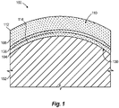
- FIG. 1 a partial view of an exemplary embodiment of an optical component in accordance with the disclosure is shown in Fig. 1 and is designated generally by reference character 100.
- FIGs. 2-3 Other embodiments of optical components in accordance with the disclosure, or aspects thereof, are provided in Figs. 2-3 , as will be described.
- the systems and methods described herein can be used to additively manufacture optical components such as mirror substrates from low thermal expansion glass.
- Fig. 1 shows an optical component 100, e.g., a mirror substrate, on a mandrel 102.
- a method of forming the optical component 100 includes positioning a preformed glass facesheet 104 on the mandrel 102.
- the facesheet 104 can be made of titania-silica glass, can be relatively thin, and is contoured for optical properties, e.g. two- or three-dimensionally contoured to provide a desired or predetermined mirror contour.
- a glass powder material is fused to a polishable surface 114 of the facesheet 104 to form a first core material layer 106 on the facesheet 104. Glass powder material is then successively fused in a plurality of additional core material layers 108 to build a core material structure 110 on the facesheet 104.
- the final layer 112 is fused at the surface of core material structure 110 opposite the facesheet 104 from the first layer 106.
- the facesheet 104 becomes part of the finished optical component 100.
- the method includes depositing liquid slurry that includes the glass powder material using an articulated extruder 124 to deposit the slurry onto the polishable surface 114 of the facesheet 104.
- Extruder 124 is articulated by conveyor system 126 for selectively depositing the slurry over only a portion of at least one of the facesheet 104, the first core material layer 106, and/or the one of the additional core material layers 108.
- extruder 124 extrudes slurry onto the top most surface of the assembly 115 that includes facesheet 104, the first core material layer 106, and/or one or more of the additional core material layers 108, as oriented in Figs. 1-2 .
- the slurry can include the glass powder material suspended in a liquid gel, water, or suitable fluid for extrusion through nozzle 128 for precise selective depositing or printing onto the assembly 115. After the slurry is deposited, it can be dried to leave behind a dried powder of the glass material ready for fusing to the assembly 115.
- the glass powder material can be configured to form a low expansion glass material when the powder is fused, for example, low expansion titania-silica glass powder can be fused into low expansion titania-silica glass.
- each such layer of powder is fused to the assembly 115 to form the cross-section of the desired geometry into the core material structure 110.
- the fusion can be achieved by using a laser beam 116.
- the laser beam 116 is shown schematically fusing the portion 118 of the deposited powder covering assembly 115 to form a layer of fused glass only in the triangle shape shown.
- the direction of movement of laser beam 116 around the pattern of the triangle is indicated by the large arrow in Fig. 3 .
- the portion 120 of the powder that is about to be fused by laser beam 116 is shown schematically in Fig. 3 .
- Mechanical abrasion grinding can optionally be used to prepare the assembly 115 after fusing a given layer prior to depositing the slurry for the next layer, e.g., to ensure that the fused layer is uniform in thickness.
- Successively fusing layers as described herein can include fusing glass powder material so as to vary material properties in successive layers and/or varying material properties based on position in a given layer.
- the triangular portion 118 in Fig. 2 can be formed of glass with a first set of material properties
- the remaining portions 122 of the surface of assembly 115 can be formed of a glass with a second set of material properties so that a given layer 108 has different sets of material properties within itself as a function of location within that layer 108.
- the facesheet 104 serves as a build plate and also becomes part of the finished product.
- the final layer 112 and or opposite surface 130 of the face sheet 104 shown in Fig. 1 can be polished and coated.
Landscapes
- Chemical & Material Sciences (AREA)
- Engineering & Computer Science (AREA)
- Materials Engineering (AREA)
- Organic Chemistry (AREA)
- Chemical Kinetics & Catalysis (AREA)
- General Chemical & Material Sciences (AREA)
- Geochemistry & Mineralogy (AREA)
- Life Sciences & Earth Sciences (AREA)
- Manufacturing & Machinery (AREA)
- Physics & Mathematics (AREA)
- Optics & Photonics (AREA)
- Health & Medical Sciences (AREA)
- Dispersion Chemistry (AREA)
- Toxicology (AREA)
- General Physics & Mathematics (AREA)
- Plasma & Fusion (AREA)
- Ceramic Engineering (AREA)
- Application Of Or Painting With Fluid Materials (AREA)
- Laminated Bodies (AREA)
- Surface Treatment Of Optical Elements (AREA)
- Surface Treatment Of Glass (AREA)
Abstract
Description
- The present disclosure relates to optics and additive manufacturing, and more particularly to additively manufacturing optics, e.g., from low expansion glass.
- Conventional lightweight glass mirror substrates are generated with subtractive manufacturing, milling, grinding, polishing, or etching away material from a large glass boule. These processes can create a stiff, lightweight glass structure with a precisely shaped optical surface, which remains stable under thermal and mechanical loads. But because glass is fragile, it is challenging to manufacture many small, intricate features with these conventional processes, and such intricate features can be important to manufacturing lightweight optics.
- The conventional techniques have been considered satisfactory for their intended purpose. However, there is an ever present need for improved manufacturing of glass optics such as mirror substrates. This disclosure provides a solution for this problem.
- A method of forming an optical component includes depositing slurry including glass powder material onto a facesheet and fusing the glass powder material to a facesheet to form a first core material layer on the facesheet. The method also includes successively fusing glass powder material in a plurality of additional core material layers to build a core material structure on the facesheet.
- The method can include positioning the facesheet on a mandrel prior to fusing glass powder material to the facesheet. Fusing glass powder material to the facesheet can include fusing the glass powder material to a polishable surface of the facesheet. At least one of depositing slurry including glass powder material and successively fusing glass powder material in a plurality of additional core material layers can include selectively depositing slurry including glass powder material over only a portion of at least one of the facesheet, the first core material layer, and/or the one of the additional core material layers. Depositing the slurry can include extruding the slurry from an extruder. Fusing glass powder material can include fusing low expansion glass powder into low expansion glass, e.g., with a laser. Fusing glass powder material can include fusing low expansion titania-silica glass powder into low expansion titania-silica glass. Fusing glass powder material to a facesheet can include fusing glass powder material to a facesheet that is contoured for optical properties.
- Successively fusing glass powder material can include forming a mirror substrate. Forming a mirror substrate can include forming an optimal three-dimensional mirror topology that minimizes the mass of mirror substrate while providing a level of stiffness and stability above a predetermined minimum requirement. Successively fusing glass powder material can include varying material properties in successive layers and/or varying material properties based on position in the successive layers.
- An optical component includes a glass facesheet. A first layer of low expansion glass is fused to the glass facesheet. A plurality of successively fused layers form a core material structure on an assembly that includes the facesheet and the first layer.
- The facesheet can be contoured for optical properties in at least one of two-dimensions or three-dimensions. The facesheet can include a polishable surface, wherein the first layer is fused to the polishable surface of the facesheet. The first layer and the plurality of successively fused layers can include fused low expansion glass powder material, e.g., low expansion titania-silica glass powder. The facesheet, first layer, and successively fused layers can form a mirror substrate. The mirror substrate can include an optimal three-dimensional mirror topology that minimizes the mass of mirror substrate while providing a level of stiffness and stability above a predetermined minimum requirement. The plurality of successively fused layers can include glass material with material properties that vary in successive layers and or that vary based on position within the core material structure.
- These and other features of the systems and methods of the subject disclosure will become more readily apparent to those skilled in the art from the following detailed description of the preferred embodiments taken in conjunction with the drawings.
- So that those skilled in the art to which the subject disclosure appertains will readily understand how to make and use the devices and methods of the subject disclosure without undue experimentation, preferred embodiments thereof will be described in detail herein below with reference to certain figures, wherein:
-
Fig. 1 is a schematic side elevation view of an exemplary embodiment of a mirror substrate constructed in accordance with the present disclosure, showing the mandrel and the facesheet with successive layers of additively manufactured core material structure deposited on the facesheet; -
Fig. 2 is a schematic perspective view of the mirror substrate ofFig. 1 , showing the extruder selectively depositing a slurry of glass powder material; and -
Fig. 3 is a schematic plan view of the mirror substrate ofFig. 1 , showing a laser beam fusing the powder material. - Reference will now be made to the drawings wherein like reference numerals identify similar structural features or aspects of the subject disclosure. For purposes of explanation and illustration, and not limitation, a partial view of an exemplary embodiment of an optical component in accordance with the disclosure is shown in
Fig. 1 and is designated generally byreference character 100. Other embodiments of optical components in accordance with the disclosure, or aspects thereof, are provided inFigs. 2-3 , as will be described. The systems and methods described herein can be used to additively manufacture optical components such as mirror substrates from low thermal expansion glass. -
Fig. 1 shows anoptical component 100, e.g., a mirror substrate, on amandrel 102. A method of forming theoptical component 100 includes positioning apreformed glass facesheet 104 on themandrel 102. Thefacesheet 104 can be made of titania-silica glass, can be relatively thin, and is contoured for optical properties, e.g. two- or three-dimensionally contoured to provide a desired or predetermined mirror contour. A glass powder material is fused to apolishable surface 114 of thefacesheet 104 to form a firstcore material layer 106 on thefacesheet 104. Glass powder material is then successively fused in a plurality of additionalcore material layers 108 to build acore material structure 110 on thefacesheet 104. Thefinal layer 112 is fused at the surface ofcore material structure 110 opposite thefacesheet 104 from thefirst layer 106. Thefacesheet 104 becomes part of the finishedoptical component 100. - With reference now to
Fig. 2 , the method includes depositing liquid slurry that includes the glass powder material using an articulatedextruder 124 to deposit the slurry onto thepolishable surface 114 of thefacesheet 104. Extruder 124 is articulated by conveyor system 126 for selectively depositing the slurry over only a portion of at least one of thefacesheet 104, the firstcore material layer 106, and/or the one of the additionalcore material layers 108. In other words,extruder 124 extrudes slurry onto the top most surface of the assembly 115 that includesfacesheet 104, the firstcore material layer 106, and/or one or more of the additionalcore material layers 108, as oriented inFigs. 1-2 . The slurry can include the glass powder material suspended in a liquid gel, water, or suitable fluid for extrusion throughnozzle 128 for precise selective depositing or printing onto the assembly 115. After the slurry is deposited, it can be dried to leave behind a dried powder of the glass material ready for fusing to the assembly 115. The glass powder material can be configured to form a low expansion glass material when the powder is fused, for example, low expansion titania-silica glass powder can be fused into low expansion titania-silica glass. - Referring now to
Fig. 3 , each such layer of powder is fused to the assembly 115 to form the cross-section of the desired geometry into thecore material structure 110. The fusion can be achieved by using alaser beam 116. InFig. 3 , thelaser beam 116 is shown schematically fusing theportion 118 of the deposited powder covering assembly 115 to form a layer of fused glass only in the triangle shape shown. The direction of movement oflaser beam 116 around the pattern of the triangle is indicated by the large arrow inFig. 3 . Theportion 120 of the powder that is about to be fused bylaser beam 116 is shown schematically inFig. 3 . Mechanical abrasion grinding can optionally be used to prepare the assembly 115 after fusing a given layer prior to depositing the slurry for the next layer, e.g., to ensure that the fused layer is uniform in thickness. - This technique allows for forming a mirror substrate, or other optical component, with an optimal three-dimensional topology that minimizes the mass of mirror substrate while providing a level of stiffness and stability above a predetermined minimum requirement. Successively fusing layers as described herein can include fusing glass powder material so as to vary material properties in successive layers and/or varying material properties based on position in a given layer. For example, the
triangular portion 118 inFig. 2 can be formed of glass with a first set of material properties, and the remainingportions 122 of the surface of assembly 115 can be formed of a glass with a second set of material properties so that a givenlayer 108 has different sets of material properties within itself as a function of location within thatlayer 108. - Unlike conventional additive manufacturing, where a part is printed on a build plate and later removed therefrom, the
facesheet 104 serves as a build plate and also becomes part of the finished product. As a finishing process, thefinal layer 112 and oropposite surface 130 of theface sheet 104 shown inFig. 1 can be polished and coated. - The methods and systems of the present disclosure, as described above and shown in the drawings, provide for optical components with superior properties potentially including very intricate features, optimal three-dimensional geometric topologies, including amorphous topologies with smaller more intricate features than can be reliably produced using conventional techniques, to minimize mass, e.g., of mirror substrates, while achieving required stiffness and stability for given applications and loads. It is also possible to provide quicker fabrication of low expansion glass using techniques disclosed herein, compared to conventional techniques, and it is possible to make larger glass mirror substrates than in convention techniques. With respect to allowing making larger glass mirror substrates than are possible with conventional techniques using build plates, this stems from the fact that under conventional techniques, the high temperatures of additive manufacturing can case thermal stresses during manufacture that warp a part and can cause it to peel off from the build-plate. This peeling process limits how large a component can be manufactured under conventional additive manufacturing techniques, but it is not a limitation for techniques disclosed herein. The thermal expansion behavior and viscoelastic behavior of titania-silica glass at high temperatures is a key enabler of larger additively manufactured structures. The fusing of the additively manufactured layers to the build plate is another key enabler of larger additively manufactured structures.
- While the apparatus and methods of the subject disclosure have been shown and described with reference to preferred embodiments, those skilled in the art will readily appreciate that changes and/or modifications may be made thereto without departing from the scope of the invention defined by the claims.
- The following clauses set out features of the invention which may or may not presently be claimed in this application but which may form the basis for future amendment or a divisional application.
- 1. A method of forming an optical component (100) comprising:
- depositing slurry including glass powder material onto a facesheet (104);
- fusing the glass powder material to the facesheet to form a first core material layer (106) on the facesheet; and
- successively depositing and fusing glass powder material in at least one additional core material layer (108) to build a core material structure on the facesheet.
- 2. The method as recited in clause 1, wherein at least one of depositing slurry including glass powder material and successively fusing glass powder material includes:
selectively depositing slurry including glass powder material over only a portion of at least one of the facesheet, the first core material layer, and/or the one of the additional core material layers. - 3. The method as recited in clause 1 or 2, wherein depositing the slurry includes extruding the slurry from an extruder (124).
- 4. The method as recited in clause 1, 2 or 3, wherein fusing glass powder material includes fusing low expansion glass powder into low expansion glass with a laser, or wherein fusing glass powder material includes fusing low expansion titania-silica glass powder into low expansion titania-silica glass.
- 5. The method as recited in any preceding clause, wherein fusing glass powder material to a facesheet includes fusing glass powder material to a facesheet that is contoured for optical properties; and/or wherein fusing glass powder material to the facesheet includes fusing the glass powder material to a polishable surface of the facesheet.
- 6. The method as recited in any preceding clause, further comprising positioning the facesheet on a mandrel prior to fusing glass powder material to the facesheet.
- 7. The method as recited in any preceding clause, wherein successively fusing glass powder material includes forming a mirror substrate; and/or wherein successively fusing glass powder material includes varying material properties in successive layers; and wherein forming a mirror substrate includes forming an optimal three-dimensional mirror topology that minimizes the mass of mirror substrate while providing a level of stiffness and stability above a predetermined minimum requirement.
- 8. An optical component comprising:
- a glass facesheet (104);
- a first layer (106) of low expansion glass fused to the glass facesheet; and
- at least one successively fused layer (108) forming a core material structure on an assembly that includes the facesheet and the first layer.
- 9. The optical component as recited in clause 8, wherein the first layer and the at least one successively fused layer include fused low expansion glass powder material.
- 10. The optical component as recited in clause 9, wherein the fused low expansion glass powder material includes fused low expansion titania-silica glass powder.
- 11. The optical component as recited in clause 8, 9 or 10, wherein the facesheet is contoured for optical properties in at least one of two-dimensions or three-dimensions.
- 12. The optical component as recited in any of clause 8 to 11, wherein the facesheet includes a polishable surface, wherein the first layer is fused to the polishable surface of the facesheet.
- 13. The optical component as recited in any of clause 8 to 12, wherein the facesheet, first layer, and successively fused layers form a mirror substrate.
- 14. The optical component as recited in clause 13, wherein the mirror substrate includes an optimal three-dimensional mirror topology that minimizes the mass of mirror substrate while providing a level of stiffness and stability above a predetermined minimum requirement.
- 15. The optical component as recited in any of clause 8 to 14, wherein the plurality of successively fused layers includes glass material with material properties that vary in successive layers; and/or wherein the plurality of successively fused layers includes glass material with material properties that vary based on position within the core material structure.
Claims (15)
- A method of forming an optical component (100), comprising:forming a build plate comprising a facesheet(104) attached to a mandrel that is contoured to match the facesheet; andforming successive layers of a core material structure on the facesheet by depositing a slurry comprising a glass powder material onto the core material structure, and fusing the glass powder material to the core material structure,wherein the build plate becomes a portion of the optical component; andwherein a layer of the core material structure has a uniform thickness and is formed by:depositing a first slurry comprising a first glass powder material onto only a portion of the core material structure, and fusing the first glass powder material to the core material structure; anddepositing a second slurry comprising a second glass powder material different from the first glass powder material onto a remaining portion of the core material structure, and fusing the second glass powder material to the core material structure to complete the layer.
- The method of claim 1, wherein the first and second slurries are deposited by extruding the first and second slurries from an extruder (124).
- The method of claim 1, wherein the first and second slurries are fused by exposing the slurries to laser radiation.
- The method of claim 1, wherein the facesheet is contoured for optical properties.
- The method of claim 1, wherein following formation of the core material structure, the core material structure comprises a three-dimensional geometric topology.
- The method of claim 1, wherein the first slurry comprises the first glass powder material suspended in a liquid gel, and wherein the second slurry comprises the second glass powder material suspended in a liquid gel.
- The method of claim 1, further comprising, prior to fusing the first and second glass powder materials to the core material structure, drying the first and second slurries.
- The method of claim 1, further comprising mechanically abrading the layer of uniform thickness prior to forming a further layer of the core material structure.
- The method of claim 1, wherein at least one optical property of the first glass powder material is different from the second glass powder material.
- The method of claim 1, wherein material properties of the layer of uniform thickness vary within the layer as a function of location within the layer.
- An optical component, comprising:a facesheet (104) attached to a mandrel that is contoured to match the facesheet; anda core material structure fused to the facesheet,wherein the core material structure comprises multiple fused glass layers; andwherein a layer of the multiple fused glass layers has a uniform thickness and comprises a first portion formed of a first glass material and a second portion formed of a second glass material different from the first glass material, so that material properties of the layer vary within the layer as a function of location within the layer.
- The optical component of claim 11, wherein one or more of the fused glass layers is formed of a single type of glass material.
- The optical component of claim 12, wherein the core material structure comprises alternating layers formed of different types of glass materials.
- The optical component of claim 11, wherein the core material structure has a three-dimensional geometric topology.
- The optical component of claim 11, wherein more than one of the multiple fused glass layers has a uniform thickness and comprises different portions formed of different glass materials.
Applications Claiming Priority (2)
| Application Number | Priority Date | Filing Date | Title |
|---|---|---|---|
| US15/348,136 US20180127296A1 (en) | 2016-11-10 | 2016-11-10 | Additive manufacture of optical components |
| EP17200865.8A EP3321238B1 (en) | 2016-11-10 | 2017-11-09 | Additive manufacture of optical components |
Related Parent Applications (1)
| Application Number | Title | Priority Date | Filing Date |
|---|---|---|---|
| EP17200865.8A Division EP3321238B1 (en) | 2016-11-10 | 2017-11-09 | Additive manufacture of optical components |
Publications (2)
| Publication Number | Publication Date |
|---|---|
| EP4116269A2 true EP4116269A2 (en) | 2023-01-11 |
| EP4116269A3 EP4116269A3 (en) | 2023-04-12 |
Family
ID=60293892
Family Applications (2)
| Application Number | Title | Priority Date | Filing Date |
|---|---|---|---|
| EP22168003.6A Pending EP4116269A3 (en) | 2016-11-10 | 2017-11-09 | Additive manufacture of optical components |
| EP17200865.8A Active EP3321238B1 (en) | 2016-11-10 | 2017-11-09 | Additive manufacture of optical components |
Family Applications After (1)
| Application Number | Title | Priority Date | Filing Date |
|---|---|---|---|
| EP17200865.8A Active EP3321238B1 (en) | 2016-11-10 | 2017-11-09 | Additive manufacture of optical components |
Country Status (3)
| Country | Link |
|---|---|
| US (3) | US20180127296A1 (en) |
| EP (2) | EP4116269A3 (en) |
| JP (3) | JP7103776B2 (en) |
Families Citing this family (5)
| Publication number | Priority date | Publication date | Assignee | Title |
|---|---|---|---|---|
| US20180127296A1 (en) * | 2016-11-10 | 2018-05-10 | Goodrich Corporation | Additive manufacture of optical components |
| IT201800006000A1 (en) * | 2018-06-04 | 2019-12-04 | METHOD FOR MAKING A SAFETY GLASS AND GLASS SO OBTAINED | |
| US11975997B2 (en) * | 2020-03-31 | 2024-05-07 | Corning Incorporated | Multi-composition glass structures via 3D printing |
| US20220111439A1 (en) * | 2020-10-09 | 2022-04-14 | Raytheon Company | Three-dimensional printing of optical mirror |
| WO2024121803A1 (en) * | 2022-12-08 | 2024-06-13 | Indian Institute of Science Education and Research, Pune (IISER Pune) | A process for coating integrative patterning and functionalization of glass, and uses thereof |
Family Cites Families (21)
| Publication number | Priority date | Publication date | Assignee | Title |
|---|---|---|---|---|
| US5076700A (en) * | 1990-12-20 | 1991-12-31 | Litton Systems, Inc. | Bonded lightweight mirror structure |
| US5249785A (en) | 1992-04-20 | 1993-10-05 | Boeing Commercial Airplane Group | Reconfigurable holding fixture |
| JPH1140054A (en) * | 1997-07-17 | 1999-02-12 | Canon Inc | Paste application method and image display device |
| FI20010523A0 (en) * | 2001-03-16 | 2001-03-16 | Yli Urpo Antti | Treatment of sols, gels and mixtures thereof |
| US6997015B2 (en) | 2001-11-27 | 2006-02-14 | Corning Incorporated | EUV lithography glass structures formed by extrusion consolidation process |
| US6988377B2 (en) * | 2001-11-27 | 2006-01-24 | Corning Incorporated | Method for making extreme ultraviolet lithography structures |
| US20030226377A1 (en) | 2002-03-05 | 2003-12-11 | Barrett W. Tim | Method of making silica-titania extreme ultraviolet elements |
| JP2004004503A (en) * | 2002-12-10 | 2004-01-08 | Hoya Corp | Gradation-coloring system for spectacle lens |
| JP2005000797A (en) * | 2003-06-11 | 2005-01-06 | Nippon Sheet Glass Co Ltd | Nozzle for coating frit paste, and coater and coating method using the nozzle |
| US20060179879A1 (en) * | 2004-12-29 | 2006-08-17 | Ellison Adam J G | Adjusting expansivity in doped silica glasses |
| US20080004169A1 (en) * | 2006-06-28 | 2008-01-03 | Adam James Ellison | Ultra low expansion glass and methods for making |
| JP5308718B2 (en) * | 2008-05-26 | 2013-10-09 | 浜松ホトニクス株式会社 | Glass welding method |
| JP5535654B2 (en) * | 2008-06-11 | 2014-07-02 | 浜松ホトニクス株式会社 | Glass welding method |
| US8789390B2 (en) * | 2010-04-15 | 2014-07-29 | Corning Incorporated | Near net fused silica articles and method of making |
| US20120026473A1 (en) * | 2010-07-29 | 2012-02-02 | Michael Lucien Genier | Highly reflective, hardened silica titania article and method of making |
| CN103459341B (en) * | 2011-07-27 | 2016-05-11 | 日本电气硝子株式会社 | With the glass substrate of seal, sealing materials layer, use the manufacture method of its organic EL device and electronic device |
| US20150056415A1 (en) * | 2013-08-21 | 2015-02-26 | Goodrich Corporation | Method for manufacturing ultra low expansion glass mirror substrates |
| EP2878584B1 (en) * | 2013-11-28 | 2017-01-04 | Heraeus Quarzglas GmbH & Co. KG | Method for producing a coated component of quartz glass or fused silica |
| US11691341B2 (en) * | 2015-10-30 | 2023-07-04 | Seurat Technologies, Inc. | Part manipulation using printed manipulation points |
| US12351718B2 (en) * | 2016-06-06 | 2025-07-08 | Lawrence Livermore National Security, Llc | Engineered feedstocks for additive manufacture of glass |
| US20180127296A1 (en) * | 2016-11-10 | 2018-05-10 | Goodrich Corporation | Additive manufacture of optical components |
-
2016
- 2016-11-10 US US15/348,136 patent/US20180127296A1/en not_active Abandoned
-
2017
- 2017-11-09 EP EP22168003.6A patent/EP4116269A3/en active Pending
- 2017-11-09 JP JP2017216174A patent/JP7103776B2/en active Active
- 2017-11-09 EP EP17200865.8A patent/EP3321238B1/en active Active
-
2021
- 2021-07-06 US US17/368,380 patent/US12209044B2/en active Active
-
2022
- 2022-07-07 JP JP2022109592A patent/JP7448592B2/en active Active
-
2024
- 2024-02-29 JP JP2024030030A patent/JP7853344B2/en active Active
-
2025
- 2025-01-27 US US19/037,966 patent/US20250276931A1/en active Pending
Also Published As
| Publication number | Publication date |
|---|---|
| US20220169550A1 (en) | 2022-06-02 |
| EP3321238B1 (en) | 2022-04-13 |
| JP2022171650A (en) | 2022-11-11 |
| JP2024071394A (en) | 2024-05-24 |
| US20250276931A1 (en) | 2025-09-04 |
| JP2018099677A (en) | 2018-06-28 |
| US20180127296A1 (en) | 2018-05-10 |
| JP7448592B2 (en) | 2024-03-12 |
| JP7853344B2 (en) | 2026-04-28 |
| JP7103776B2 (en) | 2022-07-20 |
| EP3321238A1 (en) | 2018-05-16 |
| US12209044B2 (en) | 2025-01-28 |
| EP4116269A3 (en) | 2023-04-12 |
Similar Documents
| Publication | Publication Date | Title |
|---|---|---|
| US12209044B2 (en) | Additive manufacture of optical components | |
| CN107922234B (en) | Method and system for printing 3D objects | |
| US5567554A (en) | Mask for producing radomes to high precision | |
| US20180050508A1 (en) | Methods for forming partial retroreflector tooling and sheeting and devices | |
| CN106141181A (en) | Increasing material on 3-D component manufactures | |
| JP2025036721A (en) | Powder Bed Additive Manufacturing of Low Expansion Glass | |
| CN104401002A (en) | 3D printing-based curved microlens array manufacturing method | |
| CN107896488A (en) | Cutting tool and three-dimensional laminated object manufacturing device | |
| CN105372734A (en) | Microprism reflecting material manufacturing method | |
| JPH10244596A (en) | Three-dimensional shape creation method by film additive manufacturing method and three-dimensional shape creation device by this method | |
| KR101338850B1 (en) | A method for manufacturing spherical metal mold having nano structure and anti-reflective plastic lens using therof | |
| JPH054232A (en) | Manufacture of mold | |
| CN107571495B (en) | FPC reinforcing plate and manufacturing method thereof | |
| JP2006334987A (en) | Mold manufacturing method and molded product obtained thereby | |
| KR20210028829A (en) | Micro product with high aspect ratio micro pattern and manufacturing mehtod thereof | |
| US20050087912A1 (en) | Method for forming objects | |
| IT202000017086A1 (en) | PROCEDURE FOR THE REALIZATION OF OPTICAL ELEMENTS FOR OPTICS OF TELESCOPES USABLE IN SPACE MISSIONS | |
| JP5906186B2 (en) | Multipurpose mold | |
| Stone et al. | Effects of Hatch Distance and Spray Pattern on Film Morphology in Micro-Cold Spray | |
| KR20180041998A (en) | Color printing method of 3 dimensional artwork | |
| TWI574053B (en) | Reflective element and method for manufacturing the same | |
| CN118957502A (en) | Preparation method of coated part, coated part and optical element | |
| WO2025015342A3 (en) | A telescope for mass production at low cost | |
| JP2013504773A5 (en) | ||
| HK1205059A1 (en) | Coated diamond-turned replication master and associated methods |
Legal Events
| Date | Code | Title | Description |
|---|---|---|---|
| PUAI | Public reference made under article 153(3) epc to a published international application that has entered the european phase |
Free format text: ORIGINAL CODE: 0009012 |
|
| STAA | Information on the status of an ep patent application or granted ep patent |
Free format text: STATUS: THE APPLICATION HAS BEEN PUBLISHED |
|
| AC | Divisional application: reference to earlier application |
Ref document number: 3321238 Country of ref document: EP Kind code of ref document: P |
|
| AK | Designated contracting states |
Kind code of ref document: A2 Designated state(s): AL AT BE BG CH CY CZ DE DK EE ES FI FR GB GR HR HU IE IS IT LI LT LU LV MC MK MT NL NO PL PT RO RS SE SI SK SM TR |
|
| PUAL | Search report despatched |
Free format text: ORIGINAL CODE: 0009013 |
|
| AK | Designated contracting states |
Kind code of ref document: A3 Designated state(s): AL AT BE BG CH CY CZ DE DK EE ES FI FR GB GR HR HU IE IS IT LI LT LU LV MC MK MT NL NO PL PT RO RS SE SI SK SM TR |
|
| RIC1 | Information provided on ipc code assigned before grant |
Ipc: B33Y 10/00 20150101ALI20230307BHEP Ipc: C03B 19/06 20060101ALI20230307BHEP Ipc: C03C 23/00 20060101ALI20230307BHEP Ipc: C03C 17/36 20060101ALI20230307BHEP Ipc: C03C 17/34 20060101ALI20230307BHEP Ipc: C03C 17/04 20060101AFI20230307BHEP |
|
| STAA | Information on the status of an ep patent application or granted ep patent |
Free format text: STATUS: REQUEST FOR EXAMINATION WAS MADE |
|
| 17P | Request for examination filed |
Effective date: 20231012 |
|
| RBV | Designated contracting states (corrected) |
Designated state(s): AL AT BE BG CH CY CZ DE DK EE ES FI FR GB GR HR HU IE IS IT LI LT LU LV MC MK MT NL NO PL PT RO RS SE SI SK SM TR |
|
| STAA | Information on the status of an ep patent application or granted ep patent |
Free format text: STATUS: EXAMINATION IS IN PROGRESS |
|
| 17Q | First examination report despatched |
Effective date: 20260304 |