EP4116218A1 - Contact lens package and set of same - Google Patents
Contact lens package and set of same Download PDFInfo
- Publication number
- EP4116218A1 EP4116218A1 EP20923009.3A EP20923009A EP4116218A1 EP 4116218 A1 EP4116218 A1 EP 4116218A1 EP 20923009 A EP20923009 A EP 20923009A EP 4116218 A1 EP4116218 A1 EP 4116218A1
- Authority
- EP
- European Patent Office
- Prior art keywords
- contact lens
- lens package
- virtual
- engaged
- penetration
- Prior art date
- Legal status (The legal status is an assumption and is not a legal conclusion. Google has not performed a legal analysis and makes no representation as to the accuracy of the status listed.)
- Withdrawn
Links
Images




Classifications
-
- B—PERFORMING OPERATIONS; TRANSPORTING
- B65—CONVEYING; PACKING; STORING; HANDLING THIN OR FILAMENTARY MATERIAL
- B65D—CONTAINERS FOR STORAGE OR TRANSPORT OF ARTICLES OR MATERIALS, e.g. BAGS, BARRELS, BOTTLES, BOXES, CANS, CARTONS, CRATES, DRUMS, JARS, TANKS, HOPPERS, FORWARDING CONTAINERS; ACCESSORIES, CLOSURES, OR FITTINGS THEREFOR; PACKAGING ELEMENTS; PACKAGES
- B65D75/00—Packages comprising articles or materials partially or wholly enclosed in strips, sheets, blanks, tubes or webs of flexible sheet material, e.g. in folded wrappers
- B65D75/28—Articles or materials wholly enclosed in composite wrappers, i.e. wrappers formed by associating or interconnecting two or more sheets or blanks
- B65D75/30—Articles or materials enclosed between two opposed sheets or blanks having their margins united, e.g. by pressure-sensitive adhesive, crimping, heat-sealing, or welding
- B65D75/32—Articles or materials enclosed between two opposed sheets or blanks having their margins united, e.g. by pressure-sensitive adhesive, crimping, heat-sealing, or welding one or both sheets or blanks being recessed to accommodate contents
- B65D75/36—Articles or materials enclosed between two opposed sheets or blanks having their margins united, e.g. by pressure-sensitive adhesive, crimping, heat-sealing, or welding one or both sheets or blanks being recessed to accommodate contents one sheet or blank being recessed and the other formed of relatively stiff flat sheet material, e.g. blister packages, the recess or recesses being preformed
- B65D75/366—Articles or materials enclosed between two opposed sheets or blanks having their margins united, e.g. by pressure-sensitive adhesive, crimping, heat-sealing, or welding one or both sheets or blanks being recessed to accommodate contents one sheet or blank being recessed and the other formed of relatively stiff flat sheet material, e.g. blister packages, the recess or recesses being preformed and forming one compartment
-
- B—PERFORMING OPERATIONS; TRANSPORTING
- B65—CONVEYING; PACKING; STORING; HANDLING THIN OR FILAMENTARY MATERIAL
- B65D—CONTAINERS FOR STORAGE OR TRANSPORT OF ARTICLES OR MATERIALS, e.g. BAGS, BARRELS, BOTTLES, BOXES, CANS, CARTONS, CRATES, DRUMS, JARS, TANKS, HOPPERS, FORWARDING CONTAINERS; ACCESSORIES, CLOSURES, OR FITTINGS THEREFOR; PACKAGING ELEMENTS; PACKAGES
- B65D21/00—Nestable, stackable or joinable containers; Containers of variable capacity
- B65D21/02—Containers specially shaped, or provided with fittings or attachments, to facilitate nesting, stacking, or joining together
- B65D21/0209—Containers specially shaped, or provided with fittings or attachments, to facilitate nesting, stacking, or joining together stackable or joined together one-upon-the-other in the upright or upside-down position
-
- A—HUMAN NECESSITIES
- A45—HAND OR TRAVELLING ARTICLES
- A45C—PURSES; LUGGAGE; HAND CARRIED BAGS
- A45C11/00—Receptacles for purposes not provided for in groups A45C1/00-A45C9/00
- A45C11/005—Contact lens cases
-
- A—HUMAN NECESSITIES
- A45—HAND OR TRAVELLING ARTICLES
- A45C—PURSES; LUGGAGE; HAND CARRIED BAGS
- A45C11/00—Receptacles for purposes not provided for in groups A45C1/00-A45C9/00
- A45C11/04—Spectacle cases; Pince-nez cases
-
- B—PERFORMING OPERATIONS; TRANSPORTING
- B65—CONVEYING; PACKING; STORING; HANDLING THIN OR FILAMENTARY MATERIAL
- B65D—CONTAINERS FOR STORAGE OR TRANSPORT OF ARTICLES OR MATERIALS, e.g. BAGS, BARRELS, BOTTLES, BOXES, CANS, CARTONS, CRATES, DRUMS, JARS, TANKS, HOPPERS, FORWARDING CONTAINERS; ACCESSORIES, CLOSURES, OR FITTINGS THEREFOR; PACKAGING ELEMENTS; PACKAGES
- B65D21/00—Nestable, stackable or joinable containers; Containers of variable capacity
- B65D21/02—Containers specially shaped, or provided with fittings or attachments, to facilitate nesting, stacking, or joining together
- B65D21/0209—Containers specially shaped, or provided with fittings or attachments, to facilitate nesting, stacking, or joining together stackable or joined together one-upon-the-other in the upright or upside-down position
- B65D21/0212—Containers presenting local stacking elements protruding from the upper or lower edge of a side wall, e.g. handles, lugs, ribs, grooves
-
- B—PERFORMING OPERATIONS; TRANSPORTING
- B65—CONVEYING; PACKING; STORING; HANDLING THIN OR FILAMENTARY MATERIAL
- B65D—CONTAINERS FOR STORAGE OR TRANSPORT OF ARTICLES OR MATERIALS, e.g. BAGS, BARRELS, BOTTLES, BOXES, CANS, CARTONS, CRATES, DRUMS, JARS, TANKS, HOPPERS, FORWARDING CONTAINERS; ACCESSORIES, CLOSURES, OR FITTINGS THEREFOR; PACKAGING ELEMENTS; PACKAGES
- B65D75/00—Packages comprising articles or materials partially or wholly enclosed in strips, sheets, blanks, tubes or webs of flexible sheet material, e.g. in folded wrappers
- B65D75/28—Articles or materials wholly enclosed in composite wrappers, i.e. wrappers formed by associating or interconnecting two or more sheets or blanks
- B65D75/30—Articles or materials enclosed between two opposed sheets or blanks having their margins united, e.g. by pressure-sensitive adhesive, crimping, heat-sealing, or welding
- B65D75/32—Articles or materials enclosed between two opposed sheets or blanks having their margins united, e.g. by pressure-sensitive adhesive, crimping, heat-sealing, or welding one or both sheets or blanks being recessed to accommodate contents
- B65D75/325—Articles or materials enclosed between two opposed sheets or blanks having their margins united, e.g. by pressure-sensitive adhesive, crimping, heat-sealing, or welding one or both sheets or blanks being recessed to accommodate contents one sheet being recessed, and the other being a flat not- rigid sheet, e.g. puncturable or peelable foil
- B65D75/326—Articles or materials enclosed between two opposed sheets or blanks having their margins united, e.g. by pressure-sensitive adhesive, crimping, heat-sealing, or welding one or both sheets or blanks being recessed to accommodate contents one sheet being recessed, and the other being a flat not- rigid sheet, e.g. puncturable or peelable foil and forming one compartment
-
- B—PERFORMING OPERATIONS; TRANSPORTING
- B65—CONVEYING; PACKING; STORING; HANDLING THIN OR FILAMENTARY MATERIAL
- B65D—CONTAINERS FOR STORAGE OR TRANSPORT OF ARTICLES OR MATERIALS, e.g. BAGS, BARRELS, BOTTLES, BOXES, CANS, CARTONS, CRATES, DRUMS, JARS, TANKS, HOPPERS, FORWARDING CONTAINERS; ACCESSORIES, CLOSURES, OR FITTINGS THEREFOR; PACKAGING ELEMENTS; PACKAGES
- B65D2585/00—Containers, packaging elements or packages specially adapted for particular articles or materials
- B65D2585/54—Containers, packaging elements or packages specially adapted for particular articles or materials for articles of special shape not otherwise provided for
- B65D2585/545—Contact lenses
Definitions
- the present disclosure relates to a contact lens package and a set of the same.
- Patent Document 1 discloses a disposable contact lens package, including:
- Patent Document 1 Japanese Translation of PCT International Application Publication No. H11-508172
- contact lens packages are not only received at contact lens stores and opticians, but also mailed.
- a large number (e.g., several dozen) of contact lens packages are packed in a box for mailing. Such a box is then put in a purchaser's mailbox.
- One way to decrease the height of the box to reduce the possibility of redelivery is to decrease the vertical height of the two contact lens packages combined vertically to around the same level as the vertical height of a single contact lens package.
- the height of the two contact lens packages combined vertically is greater than the vertical height of a single contact lens package by a thickness of a rigid support (referred to herein as support portion), as illustrated in FIG. 6 in Patent Document 1.
- a first aspect of the present disclosure provides a contact lens package including:
- a posture of the contact lens package when the protruding portion is placed on the horizontal table while being engaged so as to fit inside the virtual penetration portion of the virtual contact lens package rotated 180 degrees from top to bottom and placed on the horizontal table coincides with a posture of the contact lens package as a single body placed on the horizontal table.
- a third aspect of the present disclosure when the contact lens package is viewed from the top, an opening is formed in a position and in a shape such that when the protruding portion is engaged with a virtual penetration portion, a bottom of a lower surface of a depression of the virtual housing portion can be engaged so as to fit.
- a vertical width of the protruding portion is equal to a vertical width of the housing portion.
- a fifth aspect of the present disclosure that is an aspect of any one of the first to fourth aspects, when the contact lens package is viewed from the top, the protruding portion and the penetration portion are formed on the same side in the support portion.
- a corner of the support portion is cut out, the corner being on a side away from the housing portion and on the same side where the protruding portion and the penetration portion are formed.
- a corner on the side away from the housing portion and opposing the cutout corner is a bent portion which bends downward and whose vertical width is equal to at least the vertical width of the protruding portion.
- An eighth aspect of the present disclosure provides a contact lens package set combining contact lens packages A, B,
- a ninth aspect of the present disclosure provides a contact lens package, including:
- a tenth aspect of the present disclosure provides a contact lens package set combining contact lens packages A, B,
- the vertical height of the two contact lens packages combined vertically can be equal to the vertical height of a single contact lens package.
- the contact lens package according to this embodiment has the following configuration. "A contact lens package including:
- a depression direction (a protruding direction of the housing as viewed from the side) of the housing portion is referred to as downward (direction toward the bottom), and the opposite direction is referred to as upward (direction toward the top), as described above.
- a direction perpendicular to the horizontal plane is referred to as a vertical direction
- a depression direction is referred to as downward.
- the bottom view illustrates the contact lens package viewed from below
- the top view illustrates the contact lens package viewed from above.
- the vertical direction is referred to as Z direction
- the upward direction is referred to as +Z direction
- the downward direction is referred to as -Z direction.
- the contact lens package being rotated 180 degrees from top to bottom indicates rotation around X axis as a rotation axis.
- outer edge used herein literally refers to, for example, an edge portion of the support portion as viewed from the top.
- inner side with respect to the outer edge is a side opposite to a side toward the outer edge, and refers to a direction away from the outer edge of the support portion, for example.
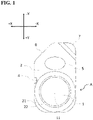
- FIG. 1 illustrates a top view (as viewed from +Z direction toward -Z direction) of the contact lens package of this embodiment.
- FIG. 2 illustrates a bottom perspective view (as viewed from an area of -X direction, +Y direction, -Z direction toward an area of +X direction, -Y direction, +Z direction) of the contact lens package of this embodiment.
- FIG. 3 illustrates a side view (as viewed from -X direction toward +X direction) of the contact lens package of this embodiment when flipped vertically (when the contact lens package is rotated 180 degrees around Y direction as a rotation axis), which is viewed from the side opposite to the side where the protruding portion is arranged in the support portion.
- the contact lens package set according to this embodiment has the following configuration. "A contact lens package set combining contact lens packages A, B,
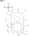
- FIG. 4 illustrates a top view (as viewed from +Z direction toward -Z direction) of the contact lens package set of this embodiment.
- FIG. 5 illustrates a top left perspective view (as viewed from an area of +X direction, +Y direction, +Z direction toward an area of -X direction, -Y direction, -Z direction) of the contact lens package set of this embodiment.
- FIG. 6 illustrates a right side view (as viewed from +X direction toward -X direction) of the contact lens package set of this embodiment, which is viewed from the side where the protruding portion is arranged in the support portion.
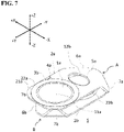
- FIG. 7 illustrates a top right perspective view (as viewed from an area of -X direction, +Y direction, +Z direction toward an area of +X direction, -Y direction, -Z direction) of the contact lens package set of this embodiment.
- Two contact lens packages according to this embodiment are prepared, and A, B are brought closer together while A remains in a normal position (the depression direction is downward and the protruding direction of a protruding portion 3a is also downward) and B is rotated 180 degrees from top to bottom around X axis direction as the rotation axis (i.e., the depression direction is upward and the protruding direction of a protruding portion 3b is upward), so that the protruding portion 3a of A is engaged with a penetration portion 4b of B, as illustrated in FIG. 5 .
- a penetration portion 4a of A is engaged with the protruding portion 3b of B.
- Each of such engagements is also referred to simply as "combination”.
- a sign indicating a feature of A is suffixed with a (or not suffixed)
- a sign indicating a feature of B is suffixed with b.
- the technical idea of the present disclosure is fully reflected not only in a set vertically combining the contact lens packages A, B, but also in a single contact lens package.
- a contact lens package B is supposed.
- the contact lens package B is also referred to as a virtual contact lens package.
- a term indicating each member constituting the virtual contact lens package e.g., the protruding portion 3 is prefixed with "virtual" (e.g., virtual protruding portion 3).
- the contact lens package A includes a housing portion 1 which houses a contact lens, and a support portion 2 which is in contact with the housing portion 1 and supports the housing portion 1.
- the housing portion 1 and the support portion 2 may be integrally molded using a resin.
- the contact lens package A may be disposable.
- the housing portion 1 is depressed when viewed from the support portion 2, and the shape of the housing portion 1 is not limited as long as the contact lens (not shown) can fit inside the depression.
- the housing portion 1 is exemplified as a bowl of an approximately spherical or approximately ellipsoidal shape. That is, the contact lens can be placed on the bottom 11 of the upper surface of the bowl.
- a sealing member (seal) (not shown) may be attached to an edge of the bowl (also including a bowl vicinity part 21 of the support portion 2 in some cases) to seal the inside of the bowl.
- the bowl vicinity part 21 of the support portion 2 may be sealed by heat fusion.
- the bowl vicinity part 21 of the support portion 2 and the bowl as the housing portion 1 are connected by a step 22.
- the step 22 is a part of the support portion 2.
- a taper may be employed instead of the step.
- the support portion 2 is not limited in shape except for features (protruding portion 3, penetration portion 4, opening 5, cutout portion 6, bent portion 7) which are provided to the support portion 2 and will be described below, as long as the support portion 2 is in contact with the housing portion 1 and can support the housing portion 1.
- the support portion 2 may have an approximately rectangular plate shape, except for the features described below. In this embodiment, a case is taken as an example where the housing portion 1 is depressed downward with respect to the plate-shaped support portion 2.
- the support portion 2 includes the protruding portion 3 formed downward from a lower surface of the support portion 2, and the penetration portion 4 being at least one of the cutout and the through hole in the support portion 2.
- the penetration portion may be a through hole formed by cutting out a portion other than the peripheral edge of the support portion 2.
- a penetration portion 4 to distinguish it from the cutout portion 6 (described below), which is a cutout in the corner of the support portion 2, and also from an opening 5 (described below), which is formed alongside the housing portion 1 in the support portion 2.
- This embodiment has a configuration such that the tip of the virtual protruding portion 3b is engaged so as to fit inside the penetration portion 4a, when the protruding portion 3a engaged so as to fit inside the virtual penetration portion 4b of the virtual contact lens package (i.e., B) is placed on the horizontal table S, the virtual contact lens package B having the same shape as the contact lens package A and being rotated 180 degrees from top to bottom and placed on the horizontal table S.
- the virtual contact lens package i.e., B
- fit inside the penetration portion 4 means that an object is located in a closed area forming the through hole or the cutout, that is, in an area cut out from the support portion 2 in which the through hole or the cutout is not provided yet, in other words, the object is made stay within the area.
- the expression “within the area” encompasses a case where the object is in contact with the boundary of the area as well.
- bottom of the lower surface 12a of the housing portion 1a fits within the opening 5b means that an apex of the bottom of the lower surface 12a does not protrude from the opening 5b.
- a posture of the contact lens package A when the protruding portion 3a is placed on the horizontal table S while being engaged so as to fit inside the virtual penetration portion 4b of the virtual contact lens package B rotated 180 degrees from top to bottom and placed on the horizontal table S coincides with a posture of the contact lens package A as a single body placed on the horizontal table S.
- the contact lens package A included in the contact lens package set according to this embodiment is preferably self-standing on the horizontal table S in a set state as in a single body state, from a viewpoint of the posture stability in a still-standing state.
- an additional protruding portion (not shown) is grounded in a still-standing state on the horizontal table S when it is in a single body state, but may rest on the lower surface of the support portion 2 of B when it is in a set state. In that case, however, a configuration is adopted where a vertical height in the set state never exceeds that in a single body state.
- the protruding portion 3a is suitable as a grounding point when it is self-standing as a single body on the horizontal table S.
- an additional protruding portion (not shown) may be provided and utilized as the grounding point.
- B bottom of the lower surface 12 of the housing portion 1 may be the grounding point.
- the bent portion 7 described below which is obtained by downwardly bending the corner (-X direction, -Y direction) of the support portion 2 may be the grounding point.
- the protruding portion 3 the lower surface of the housing portion 1, and the bent portion 7 described below are the grounding points, three-point supporting is achieved, which is preferable because of the stabilized still-standing state on the horizontal table S.
- the opening 5a is preferably formed in a position and in a shape such that when the protruding portion 3a of the contact lens package A is engaged with the penetration portion 4b of the contact lens package B, the apex of the bottom of the lower surface 12b of the depression of the virtual housing portion 1b can be engaged to fit inside the opening 5a.
- the contact lens packages of this embodiment are combined, so that the bottom of the lower surface 12b of the housing portion 1b of B can be housed in the opening 5a of the support portion 2a of A, as illustrated in FIG. 6 . Accordingly, further space saving can be achieved.
- the position and shape of the opening 5 are not limited as long as the engagement can be realized.
- the shape of the opening 5 may be an ellipse, a circle, a rectangle, a polygon, or any other shape, when viewed from the top.
- the vertical width of the protruding portion 3 is equal to the vertical width of the housing portion 1.
- the protruding portion 3 and the housing portion 1 are the grounding points. Furthermore, these vertical widths are equal to the vertical width in the set state.
- vertical width refers to a maximum vertical width of the contact lens package A or B as a single body grounded on the horizontal table S, or a maximum vertical width of a set combining A and B, in which A is arranged above B, grounded on the horizontal table S.
- the term "equal” as used herein includes the case of a perfect matching and also a case of a substantial matching.
- substantially matching includes, for example, a case where there is a difference of less than 0.50 mm (preferably less than 0.30 mm, more preferably less than 0.10 mm).
- the protruding portion 3 protrudes from the outer edge of the lower surface of the support portion 2, but the present disclosure is not limited to the case.
- the protruding portion 3 preferably protrudes downward from the outermost edge of the support portion 2 or its vicinity (for example, more than 0 mm and about 2 mm or less inside from the outermost edge).
- the protruding portion 3 and the penetration portion 4 being formed on the outer edge of the support portion 2 so as to be in contact with each other will further save space and facilitate position adjustment at the time of combination.
- the protruding portion 3 and the penetration portion 4 may be formed, separated from each other (for example, at a distance of more than 0 mm and about 5 mm or less).
- protruding portion 3 bottom view, side view.
- the protruding portion 3 it is useful for the protruding portion 3 to be molded integrally with the support portion 2, for example, using plastic, but it does not have to be so.
- an additional small protruding portion 31 may be provided inside the protruding portion 3.
- the small protruding portion 31 may protrude inward so as to come into contact with the lower surface of the support portion 2 as illustrated in FIG. 2 and FIG. 3 , or may protrude inward so as not to come into contact with the lower surface of the support portion 2.
- the small protruding portion 31 serves as a reinforcing material (rib) for the protruding portion 3, thus suppressing damage to the protruding portion 3.
- the shape of the penetration portion 4 may be determined according to the shape of the tip of the protruding portion 3.
- the outermost edge of the cutout (the opening of the cutout) may be wider than the inside (e.g., a portion 1 mm inside from the outermost edge).
- the width of the innermost part of the cutout (the bottom of the cutout) is not limited. However, the width of the innermost side of the cutout is preferably narrower than the outermost edge of the cutout (the opening of the cutout). It is because the protruding portion 3 can be more easily detached and the combined contact lens packages can be more easily released.
- the outer edge side of the cutout may be processed, for example, chamfered or rounded, thereby making it easier to insert and detach (i.e., insert/detach) the protruding portion 3 of B through the outer edge of the cutout of A.
- the protruding portion 3 and the penetration portion 4 are preferably formed on the same side (+X direction) in the support portion 2.
- the engaged state can be easily released by lifting the upper contact lens package A.
- the cutout portion 6 is preferably formed by cutting out the corner (+X direction, -Y direction) on the side (-Y direction) away from the housing portion 1 and on the same side (+X direction) as a corner where the protruding portion 3 and the penetration portion 4 are formed.
- the engaged state can be easily released by inserting a finger into the cutout portion 6, lifting up the contact lens package A on the upper side, and then turning it over to the -X direction.
- the corner (-X direction, -Y direction) on a side away from the housing portion 1 (-Y direction) and opposing the corner (+X direction, -Y direction) is preferably the bent portion 7 obtained by bending the corner (-X direction, -Y direction) downward.
- the bent portion 7 is configured separately from the protruding portion 3.
- the vertical width of the bent portion 7 is preferably equal to the vertical width of the protruding portion 3. More preferably, the vertical width of the bent portion 7 is also equal to the vertical width of the protruding portion 3 and the vertical width of the housing portion.
- the downward bending angle of the bent portion 7 may be set appropriately to satisfy these conditions. As illustrated in FIG. 7 , the dimension of the bent portion 7a may be set so that the bent portion 7a contacts the corner (-X direction, - Y direction) of the support portion 2b of the contact lens package B in the horizontal direction when the bent portion 7a is grounded on the horizontal table S.
- the corner (-X direction, -Y direction) of the support portion 2 can be set as the grounding point.
- at least the protruding portion 3 and the bent portion 7 can be set as the grounding points.
- stable two-point supporting can be achieved.
- at least the protruding portion 3 the bottom of the lower surface 12 of the housing portion 1, and the bent portion 7 described below are the grounding points, three-point supporting is achieved, which is preferable because of the more stabilized still-standing state on the horizontal table S.
- the contact lens package set of this embodiment adopts a configuration in which the two contact lens packages A and B are fixed not by friction as described in Patent Document 1, but by simple placement.
- the two contact lens packages are loosely fixed by simply placing the contact lens package A on the contact lens package B without friction, while being engaged.
- an engagement utilizing friction may be adopted, in addition to a configuration in which the contact lens package is fixed while being simply placed as in this embodiment.
- the bent portion 7a of A can be engaged by friction with the corner (-X direction, +Y direction) on the housing portion 1b side in the support portion 2b of B.
- the vertical height of the two contact lens packages when combined vertically can be equal to the vertical height of a single contact lens package.
- the suitable example is adopted, the combined state of the contact lens packages can be more easily released. On the other hand, a fixing force is reduced.
- the bent portion 7a (-X direction, -Y direction) of A is preferably utilized to be engaged by friction with a corner (-X direction, +Y direction) on the housing portion 1b side of the supporting portion 2b of B.
- a bending direction and the dimension of the bent portion 7 (-X direction, -Y direction) or the shape of the corner (-X direction, +Y direction) of the support portion 2 may be set to be engaged by friction. Even in this case, it is still easy to release the combined state.
- the housing portion 1 being depressed downward may be utilized. That is, the housing portion 1a may be grounded on the horizontal table S when the contact lens packages A and B are combined.
- the bent portion 7a on the corner of the support portion 2a may be used instead of the protruding portion 3a of this embodiment so that A as a single body can be self-standing when it is placed on the horizontal table S.
- the corner (+X direction, -Y direction) of the support portion 2a is not cut out, instead a portion extending from the corner (-X direction, -Y direction) to the corner (+X direction,-Y direction) of the support portion 2a may be utilized as the bent portion 7a.
- the corner (+X direction, -Y direction) of the support portion 2a may be utilized as another bent portion, instead of being cut out.
- the protruding portion (not shown), which is in a shape of a cross as viewed from the bottom, may be separately provided as a part of the bottom of the lower surface 12 of the housing portion 1a, as illustrated in FIG. 2 in Patent Document 1.
- the bent portion 7 can be regarded as protruding downward, it is regarded as a kind of the protruding portion 3.
- the protruding portion 3 described so far may be referred to as a first protruding portion
- the bent portion 7 may be referred to as a second protruding portion.
- the opening 5 is also regarded as a kind of the penetration portion 4.
- the penetration portion 4 described so far may be referred to as a first penetration portion
- the opening 5 may be referred to as a second penetration portion.
- a contact lens package including:
Landscapes
- Engineering & Computer Science (AREA)
- Mechanical Engineering (AREA)
- Chemical & Material Sciences (AREA)
- Composite Materials (AREA)
- Purses, Travelling Bags, Baskets, Or Suitcases (AREA)
- Packaging Frangible Articles (AREA)
- Packages (AREA)
Abstract
Description
- The present disclosure relates to a contact lens package and a set of the same.
-
Patent Document 1 discloses a disposable contact lens package, including: - a) a rigid support having an upper surface and a lens installation surface located above the upper surface; and
- b) a means for removably and frictionally attaching two of the packages in a stacked relationship against each other.
- Patent Document 1:
Japanese Translation of PCT International Application Publication No. H11-508172 - The investigation of the present inventor has revealed the following problems.
- In recent years, contact lens packages are not only received at contact lens stores and opticians, but also mailed. A large number (e.g., several dozen) of contact lens packages are packed in a box for mailing. Such a box is then put in a purchaser's mailbox.
- Space can be saved by adopting two contact lens packages that have the same shape and can be combined with each other, like the contact lens packages described in
Patent Document 1. However, the investigation by the present inventor revealed that a box filled with contact lens packages could not pass through a slot of a mailbox depending on the size of the slot. If the box cannot be dropped in the mailbox, it is usually subject to redelivery. - The number of package delivery services handled has been increasing due to the recent expansion of EC and other services. Redelivery accounts for about 20% of the number of the services handled. The redelivery causes problems such as increased costs, labor shortages, and CO2 emissions, which have become major social issues.
- One way to decrease the height of the box to reduce the possibility of redelivery is to decrease the vertical height of the two contact lens packages combined vertically to around the same level as the vertical height of a single contact lens package. On the other hand, in a case of the contact lens package described in
Patent Document 1, the height of the two contact lens packages combined vertically is greater than the vertical height of a single contact lens package by a thickness of a rigid support (referred to herein as support portion), as illustrated inFIG. 6 inPatent Document 1. - It is an object of the present disclosure to make the vertical height of the two contact lens packages combined vertically equal to the vertical height of a single contact lens package.
- A first aspect of the present disclosure provides
a contact lens package including: - a housing portion housing a contact lens; and
- a support portion supporting the housing portion,
- the housing portion being depressed when viewed from the support portion,
- a depression direction being referred to as downward, and a direction opposite to the direction being referred to as upward, and
- the support portion including
- a protruding portion formed downward, and
- a penetration portion being at least one of a cutout and a through hole in the support portion,
- the contact lens package having a configuration such that when the protruding portion engaged so as to fit inside a virtual penetration portion of a virtual contact lens package is placed on a horizontal table, a tip of a virtual protruding portion is engaged so as to fit inside the penetration portion,
- the virtual contact lens package having the same shape as the contact lens package and being rotated 180 degrees from top to bottom and placed on the horizontal table.
- In a second aspect of the present disclosure that is an aspect of the first aspect,
a posture of the contact lens package when the protruding portion is placed on the horizontal table while being engaged so as to fit inside the virtual penetration portion of the virtual contact lens package rotated 180 degrees from top to bottom and placed on the horizontal table coincides with a posture of the contact lens package as a single body placed on the horizontal table. - In a third aspect of the present disclosure that is an aspect of the first or second aspect,
when the contact lens package is viewed from the top, an opening is formed in a position and in a shape such that when the protruding portion is engaged with a virtual penetration portion, a bottom of a lower surface of a depression of the virtual housing portion can be engaged so as to fit. - In a fourth aspect of the present disclosure that is an aspect of any one of the first to third aspects,
a vertical width of the protruding portion is equal to a vertical width of the housing portion. - In a fifth aspect of the present disclosure that is an aspect of any one of the first to fourth aspects,
when the contact lens package is viewed from the top, the protruding portion and the penetration portion are formed on the same side in the support portion. - In a sixth aspect of the present disclosure that is an aspect of the fifth aspect,
when the contact lens package is viewed from the top, in the support portion, a corner of the support portion is cut out, the corner being on a side away from the housing portion and on the same side where the protruding portion and the penetration portion are formed. - In a seventh aspect of the present disclosure that is an aspect of the sixth aspect,
in the support portion, a corner on the side away from the housing portion and opposing the cutout corner is a bent portion which bends downward and whose vertical width is equal to at least the vertical width of the protruding portion. - An eighth aspect of the present disclosure provides
a contact lens package set combining contact lens packages A, B, - the contact lens package A being of any one of the first to seventh aspects,
- the contact lens package B having the same shape as the contact lens package A and being rotated 180 degrees from top to bottom,
- a vertical width of the contact lens package set being equal to a vertical width of each of the contact lens packages A, B when the protruding portion of the contact lens package A is engaged with the penetration portion of the contact lens package B, and the penetration portion of the contact lens package A is engaged with the protruding portion of the contact lens package B.
- A ninth aspect of the present disclosure provides
a contact lens package, including: - a housing portion housing a contact lens; and
- a support portion supporting the housing portion,
- the housing portion being depressed when viewed from the support portion,
- a depression direction being referred to as downward, and a direction opposite to the direction being referred to as upward, and
- the support portion including:
- a protruding portion formed downward, and
- a penetration portion being at least one of a cutout and a through hole in the support portion,
- the contact lens package having at least one of the following configurations i) and ii):
- i) a configuration such that a bottom of a lower surface of a virtual housing portion is engaged so as to fit inside the penetration portion, when the housing portion engaged so as to fit inside a virtual penetration portion of a virtual contact lens package is placed on a horizontal table,
the virtual contact lens package having the same shape as the contact lens package and being rotated 180 degrees from top to bottom and placed on the horizontal table; and - ii) a configuration such that a tip of a virtual protruding portion is engaged so as to fit inside the penetration portion, when the protruding portion engaged so as to fit inside a virtual penetration portion of a virtual contact lens package is placed on a horizontal table,
- i) a configuration such that a bottom of a lower surface of a virtual housing portion is engaged so as to fit inside the penetration portion, when the housing portion engaged so as to fit inside a virtual penetration portion of a virtual contact lens package is placed on a horizontal table,
- the virtual contact lens package having the same shape as the contact lens package, and being rotated 180 degrees from top to bottom and placed on the horizontal table.
- A tenth aspect of the present disclosure provides
a contact lens package set combining contact lens packages A, B, - the contact lens package A being of the ninth aspect,
- the contact lens package B having the same shape as the contact lens package A and being rotated 180 degrees from top to bottom,
- a vertical width of the contact lens package set being equal to a vertical width of each of the contact lens packages A, B, when the housing portion of the contact lens package A is engaged with the penetration portion of the contact lens package B, and the penetration portion of the contact lens package A is engaged with the housing portion of the contact lens package B.
- According to the present disclosure, the vertical height of the two contact lens packages combined vertically can be equal to the vertical height of a single contact lens package.
-
-
FIG. 1 illustrates a top view (as viewed from +Z direction toward -Z direction) of a contact lens package of this embodiment. -
FIG. 2 illustrates a bottom perspective view (as viewed from an area of -X direction, +Y direction, -Z direction toward an area of +X direction, -Y direction, +Z direction) of the contact lens package of this embodiment. -
FIG. 3 illustrates a side view (as viewed from -X direction toward +X direction) of the contact lens package of this embodiment when flipped vertically (when the contact lens package is rotated 180 degrees around Y direction as a rotation axis), which is viewed from a side opposite to a side where the protruding portion is arranged in the support portion. -
FIG. 4 illustrates a top view (as viewed from +Z direction toward -Z direction) of a contact lens package set of this embodiment. -
FIG. 5 illustrates a top left perspective view (as viewed from an area of +X direction, +Y direction, +Z direction toward an area of -X direction, -Y direction, -Z direction) of the contact lens package set of this embodiment. -
FIG. 6 illustrates a right side view (as viewed from +X direction toward -X direction) of the contact lens package set of this embodiment, which is viewed from the side where the protruding portion is arranged in the support portion. -
FIG. 7 illustrates a top right perspective view (as viewed from an area of -X direction, +Y direction, +Z direction toward an area of +X direction, -Y direction, -Z direction) of the contact lens package set of this embodiment. - Embodiments of the present disclosure will be described hereafter, with reference to the drawings. For the contents not described in the present specification, the known structure of the contact lens package may be adopted.
- The contact lens package according to this embodiment has the following configuration.
"A contact lens package including: - a housing portion housing a contact lens; and
- a support portion supporting the housing portion,
- the housing portion being depressed when viewed from the support portion,
- a depression direction being referred to as downward, and a direction opposite to the direction being referred to as upward, and
- the support portion including
- a protruding portion formed downward, and
- a penetration portion being at least one of a cutout and a through hole in the support portion,
- the contact lens package having a configuration such that when the protruding portion engaged so as to fit inside a virtual penetration portion of a virtual contact lens package is placed on a horizontal table, a tip of a virtual protruding portion is engaged so as to fit inside the penetration portion,
- the virtual contact lens package having the same shape as the contact lens package and being rotated 180 degrees from top to bottom and placed on the horizontal table."
- In this embodiment, a depression direction (a protruding direction of the housing as viewed from the side) of the housing portion is referred to as downward (direction toward the bottom), and the opposite direction is referred to as upward (direction toward the top), as described above. In other words, when the plane formed of the support portion (an edge of a hole) in the vicinity of the housing portion is regarded as a horizontal plane, a direction perpendicular to the horizontal plane is referred to as a vertical direction, and a depression direction is referred to as downward. The bottom view illustrates the contact lens package viewed from below, and the top view illustrates the contact lens package viewed from above. The vertical direction is referred to as Z direction, the upward direction is referred to as +Z direction, and the downward direction is referred to as -Z direction.
- The direction, in which the housing portion and an opening described below are aligned and which is a long direction when the support portion of the contact lens package is viewed from the top, is referred to as Y direction, the direction from the opening toward the housing portion is referred to as +Y direction, and the opposite direction is referred to as -Y direction. The direction, which is perpendicular to Z direction and Y direction and is a short direction when the support portion of the contact lens package is viewed from the top, is referred to as X direction, the side where the protruding portion and the penetration portion are arranged is referred to as +X direction, and the opposite direction is referred to as -X direction.
- In the present specification, "the contact lens package being rotated 180 degrees from top to bottom" indicates rotation around X axis as a rotation axis.
- The term "outer edge" used herein literally refers to, for example, an edge portion of the support portion as viewed from the top. The term "inner side" with respect to the outer edge is a side opposite to a side toward the outer edge, and refers to a direction away from the outer edge of the support portion, for example.
-
FIG. 1 illustrates a top view (as viewed from +Z direction toward -Z direction) of the contact lens package of this embodiment. -
FIG. 2 illustrates a bottom perspective view (as viewed from an area of -X direction, +Y direction, -Z direction toward an area of +X direction, -Y direction, +Z direction) of the contact lens package of this embodiment. -
FIG. 3 illustrates a side view (as viewed from -X direction toward +X direction) of the contact lens package of this embodiment when flipped vertically (when the contact lens package is rotated 180 degrees around Y direction as a rotation axis), which is viewed from the side opposite to the side where the protruding portion is arranged in the support portion. - The contact lens package set according to this embodiment has the following configuration.
"A contact lens package set combining contact lens packages A, B, - the contact lens package B having the same shape as the contact lens package A and being rotated 180 degrees from top to bottom,
- a vertical width of the contact lens package set being equal to a vertical width of each of the contact lens packages A, B when the protruding portion of the contact lens package A is engaged with the penetration portion of the contact lens package B, and the penetration portion of the contact lens package A is engaged with the protruding portion of the contact lens package B."
-
FIG. 4 illustrates a top view (as viewed from +Z direction toward -Z direction) of the contact lens package set of this embodiment. -
FIG. 5 illustrates a top left perspective view (as viewed from an area of +X direction, +Y direction, +Z direction toward an area of -X direction, -Y direction, -Z direction) of the contact lens package set of this embodiment. -
FIG. 6 illustrates a right side view (as viewed from +X direction toward -X direction) of the contact lens package set of this embodiment, which is viewed from the side where the protruding portion is arranged in the support portion. -
FIG. 7 illustrates a top right perspective view (as viewed from an area of -X direction, +Y direction, +Z direction toward an area of +X direction, -Y direction, -Z direction) of the contact lens package set of this embodiment. - Two contact lens packages according to this embodiment, each designated as A and B, are prepared, and A, B are brought closer together while A remains in a normal position (the depression direction is downward and the protruding direction of a protruding
portion 3a is also downward) and B is rotated 180 degrees from top to bottom around X axis direction as the rotation axis (i.e., the depression direction is upward and the protruding direction of a protrudingportion 3b is upward), so that the protrudingportion 3a of A is engaged with a penetration portion 4b of B, as illustrated inFIG. 5 . At the same time, apenetration portion 4a of A is engaged with the protrudingportion 3b of B. Each of such engagements is also referred to simply as "combination". A sign indicating a feature of A is suffixed with a (or not suffixed), and a sign indicating a feature of B is suffixed with b. - The technical idea of the present disclosure is fully reflected not only in a set vertically combining the contact lens packages A, B, but also in a single contact lens package. In the illustration of the single contact lens package (e.g., contact lens package A), a contact lens package B is supposed. In such a case, the contact lens package B is also referred to as a virtual contact lens package. In the present specification, a term indicating each member constituting the virtual contact lens package (e.g., the protruding portion 3) is prefixed with "virtual" (e.g., virtual protruding portion 3).
- The contact lens package A according to this embodiment includes a
housing portion 1 which houses a contact lens, and asupport portion 2 which is in contact with thehousing portion 1 and supports thehousing portion 1. - The
housing portion 1 and thesupport portion 2 may be integrally molded using a resin. In addition, the contact lens package A may be disposable. - The
housing portion 1 is depressed when viewed from thesupport portion 2, and the shape of thehousing portion 1 is not limited as long as the contact lens (not shown) can fit inside the depression. In this embodiment, thehousing portion 1 is exemplified as a bowl of an approximately spherical or approximately ellipsoidal shape. That is, the contact lens can be placed on the bottom 11 of the upper surface of the bowl. - When actually housing the contact lens in the bowl, a sealing member (seal) (not shown) may be attached to an edge of the bowl (also including a
bowl vicinity part 21 of thesupport portion 2 in some cases) to seal the inside of the bowl. - At this time, the
bowl vicinity part 21 of thesupport portion 2 may be sealed by heat fusion. Thebowl vicinity part 21 of thesupport portion 2 and the bowl as thehousing portion 1 are connected by astep 22. Thestep 22 is a part of thesupport portion 2. A taper may be employed instead of the step. - The
support portion 2 is not limited in shape except for features (protrudingportion 3,penetration portion 4,opening 5,cutout portion 6, bent portion 7) which are provided to thesupport portion 2 and will be described below, as long as thesupport portion 2 is in contact with thehousing portion 1 and can support thehousing portion 1. Thesupport portion 2 may have an approximately rectangular plate shape, except for the features described below. In this embodiment, a case is taken as an example where thehousing portion 1 is depressed downward with respect to the plate-shapedsupport portion 2. - The
support portion 2 includes the protrudingportion 3 formed downward from a lower surface of thesupport portion 2, and thepenetration portion 4 being at least one of the cutout and the through hole in thesupport portion 2. In this embodiment, a case is taken as an example where a peripheral edge of thesupport portion 2 is cut out. However, the penetration portion may be a through hole formed by cutting out a portion other than the peripheral edge of thesupport portion 2. - In this embodiment, either a cutout or a through hole which corresponds to and engaged with the protruding
portion 3 is referred to as apenetration portion 4 to distinguish it from the cutout portion 6 (described below), which is a cutout in the corner of thesupport portion 2, and also from an opening 5 (described below), which is formed alongside thehousing portion 1 in thesupport portion 2. - This embodiment has a configuration such that the tip of the virtual protruding
portion 3b is engaged so as to fit inside thepenetration portion 4a, when the protrudingportion 3a engaged so as to fit inside the virtual penetration portion 4b of the virtual contact lens package (i.e., B) is placed on the horizontal table S, the virtual contact lens package B having the same shape as the contact lens package A and being rotated 180 degrees from top to bottom and placed on the horizontal table S. - In the present specification, "fit inside the penetration portion 4 (or
opening 5 described below)" means that an object is located in a closed area forming the through hole or the cutout, that is, in an area cut out from thesupport portion 2 in which the through hole or the cutout is not provided yet, in other words, the object is made stay within the area. The expression "within the area" encompasses a case where the object is in contact with the boundary of the area as well. For example, "bottom of the lower surface 12a of thehousing portion 1a fits within the opening 5b" means that an apex of the bottom of the lower surface 12a does not protrude from the opening 5b. - It is preferable that a posture of the contact lens package A when the protruding
portion 3a is placed on the horizontal table S while being engaged so as to fit inside the virtual penetration portion 4b of the virtual contact lens package B rotated 180 degrees from top to bottom and placed on the horizontal table S coincides with a posture of the contact lens package A as a single body placed on the horizontal table S. In other words, the contact lens package A included in the contact lens package set according to this embodiment is preferably self-standing on the horizontal table S in a set state as in a single body state, from a viewpoint of the posture stability in a still-standing state. - On the other hand, an additional protruding portion (not shown) is grounded in a still-standing state on the horizontal table S when it is in a single body state, but may rest on the lower surface of the
support portion 2 of B when it is in a set state. In that case, however, a configuration is adopted where a vertical height in the set state never exceeds that in a single body state. - Note that the protruding
portion 3a is suitable as a grounding point when it is self-standing as a single body on the horizontal table S. In addition to the protrudingportion 3a, an additional protruding portion (not shown) may be provided and utilized as the grounding point. In that case, it is advisable to separately provide B with an additional penetration portion (not shown) corresponding to the additional protruding portion of A. Alternatively, bottom of thelower surface 12 of thehousing portion 1 may be the grounding point. Alternatively, thebent portion 7 described below which is obtained by downwardly bending the corner (-X direction, -Y direction) of thesupport portion 2 may be the grounding point. In a case where at least the protrudingportion 3, the lower surface of thehousing portion 1, and thebent portion 7 described below are the grounding points, three-point supporting is achieved, which is preferable because of the stabilized still-standing state on the horizontal table S. - The
opening 5a is preferably formed in a position and in a shape such that when the protrudingportion 3a of the contact lens package A is engaged with the penetration portion 4b of the contact lens package B, the apex of the bottom of thelower surface 12b of the depression of thevirtual housing portion 1b can be engaged to fit inside theopening 5a. - When this configuration is adopted, the contact lens packages of this embodiment are combined, so that the bottom of the
lower surface 12b of thehousing portion 1b of B can be housed in theopening 5a of thesupport portion 2a of A, as illustrated inFIG. 6 . Accordingly, further space saving can be achieved. - The position and shape of the
opening 5 are not limited as long as the engagement can be realized. For example, the shape of theopening 5 may be an ellipse, a circle, a rectangle, a polygon, or any other shape, when viewed from the top. - It is preferable that the vertical width of the protruding
portion 3 is equal to the vertical width of thehousing portion 1. In this case, the protrudingportion 3 and thehousing portion 1 are the grounding points. Furthermore, these vertical widths are equal to the vertical width in the set state. - The term "vertical width" as used herein refers to a maximum vertical width of the contact lens package A or B as a single body grounded on the horizontal table S, or a maximum vertical width of a set combining A and B, in which A is arranged above B, grounded on the horizontal table S.
- The term "equal" as used herein includes the case of a perfect matching and also a case of a substantial matching. The term "substantial matching" includes, for example, a case where there is a difference of less than 0.50 mm (preferably less than 0.30 mm, more preferably less than 0.10 mm).
- This embodiment illustrates a case where the protruding
portion 3 protrudes from the outer edge of the lower surface of thesupport portion 2, but the present disclosure is not limited to the case. However, in consideration of space saving when the contact lens packages A and B are combined, the protrudingportion 3 preferably protrudes downward from the outermost edge of thesupport portion 2 or its vicinity (for example, more than 0 mm and about 2 mm or less inside from the outermost edge). - The protruding
portion 3 and thepenetration portion 4 being formed on the outer edge of thesupport portion 2 so as to be in contact with each other will further save space and facilitate position adjustment at the time of combination. However, the protrudingportion 3 and thepenetration portion 4 may be formed, separated from each other (for example, at a distance of more than 0 mm and about 5 mm or less). After all, when the arrangement of thepenetration portion 4 of A and the position of the protrudingportion 3 of B are symmetric (for example, with respect to Y direction), A and B can be combined. Therefore, there is no restriction on whether the protrudingportion 3 and thepenetration portion 4 are separated from each other. - There is no restriction on the shape of the protruding portion 3 (bottom view, side view). In disposable application, it is useful for the protruding
portion 3 to be molded integrally with thesupport portion 2, for example, using plastic, but it does not have to be so. - Note that an additional small protruding
portion 31 may be provided inside the protrudingportion 3. In this case, the small protrudingportion 31 may protrude inward so as to come into contact with the lower surface of thesupport portion 2 as illustrated inFIG. 2 andFIG. 3 , or may protrude inward so as not to come into contact with the lower surface of thesupport portion 2. Anyway, the small protrudingportion 31 serves as a reinforcing material (rib) for the protrudingportion 3, thus suppressing damage to the protrudingportion 3. - The shape of the
penetration portion 4 may be determined according to the shape of the tip of the protrudingportion 3. In the top view of the contact lens package, in a case where thepenetration portion 4 is the cutout, the outermost edge of the cutout (the opening of the cutout) may be wider than the inside (e.g., aportion 1 mm inside from the outermost edge). The width of the innermost part of the cutout (the bottom of the cutout) is not limited. However, the width of the innermost side of the cutout is preferably narrower than the outermost edge of the cutout (the opening of the cutout). It is because the protrudingportion 3 can be more easily detached and the combined contact lens packages can be more easily released. - For example, in a case where the
penetration portion 4 is a cutout, the outer edge side of the cutout may be processed, for example, chamfered or rounded, thereby making it easier to insert and detach (i.e., insert/detach) the protrudingportion 3 of B through the outer edge of the cutout of A. - When the contact lens package is viewed from the top, the protruding
portion 3 and thepenetration portion 4 are preferably formed on the same side (+X direction) in thesupport portion 2. - When releasing the contact lens packages which adopt this configuration and have been combined with each other, the engaged state can be easily released by lifting the upper contact lens package A.
- Furthermore, in the
support portion 2, thecutout portion 6 is preferably formed by cutting out the corner (+X direction, -Y direction) on the side (-Y direction) away from thehousing portion 1 and on the same side (+X direction) as a corner where the protrudingportion 3 and thepenetration portion 4 are formed. - When releasing the contact lens packages which adopt this configuration and have been combined with each other, the engaged state can be easily released by inserting a finger into the
cutout portion 6, lifting up the contact lens package A on the upper side, and then turning it over to the -X direction. - In the
support portion 2, the corner (-X direction, -Y direction) on a side away from the housing portion 1 (-Y direction) and opposing the corner (+X direction, -Y direction) is preferably thebent portion 7 obtained by bending the corner (-X direction, -Y direction) downward. In this embodiment, thebent portion 7 is configured separately from the protrudingportion 3. - The vertical width of the
bent portion 7 is preferably equal to the vertical width of the protrudingportion 3. More preferably, the vertical width of thebent portion 7 is also equal to the vertical width of the protrudingportion 3 and the vertical width of the housing portion. The downward bending angle of thebent portion 7 may be set appropriately to satisfy these conditions. As illustrated inFIG. 7 , the dimension of thebent portion 7a may be set so that thebent portion 7a contacts the corner (-X direction, - Y direction) of thesupport portion 2b of the contact lens package B in the horizontal direction when thebent portion 7a is grounded on the horizontal table S. - By adopting this configuration, the corner (-X direction, -Y direction) of the
support portion 2 can be set as the grounding point. With this setting, at least the protrudingportion 3 and thebent portion 7 can be set as the grounding points. When the ground contact area of the protrudingportion 3 and the ground contact area of thebent portion 7 are increased, stable two-point supporting can be achieved. On the other hand, in a case where at least the protrudingportion 3, the bottom of thelower surface 12 of thehousing portion 1, and thebent portion 7 described below are the grounding points, three-point supporting is achieved, which is preferable because of the more stabilized still-standing state on the horizontal table S. - The technical scope of the present disclosure is not limited to the embodiment described above but includes various modes and modifications as far as the specific effects obtained by the constituent features of the disclosure and combinations thereof can be derived.
- The contact lens package set of this embodiment adopts a configuration in which the two contact lens packages A and B are fixed not by friction as described in
Patent Document 1, but by simple placement. In other words, as a means of fixing the contact lens packages of the same shape, the two contact lens packages are loosely fixed by simply placing the contact lens package A on the contact lens package B without friction, while being engaged. On the other hand, as a means of fixing the contact lens package, an engagement utilizing friction may be adopted, in addition to a configuration in which the contact lens package is fixed while being simply placed as in this embodiment. For example, thebent portion 7a of A can be engaged by friction with the corner (-X direction, +Y direction) on thehousing portion 1b side in thesupport portion 2b of B. - According to this embodiment, the vertical height of the two contact lens packages when combined vertically can be equal to the vertical height of a single contact lens package. When the suitable example is adopted, the combined state of the contact lens packages can be more easily released. On the other hand, a fixing force is reduced.
- To compensate for the fixing force, the
bent portion 7a (-X direction, -Y direction) of A is preferably utilized to be engaged by friction with a corner (-X direction, +Y direction) on thehousing portion 1b side of the supportingportion 2b of B. A bending direction and the dimension of the bent portion 7 (-X direction, -Y direction) or the shape of the corner (-X direction, +Y direction) of thesupport portion 2 may be set to be engaged by friction. Even in this case, it is still easy to release the combined state. It is because the engagement between the protrudingportion 3a and the penetration portion 4b, which has been described so far, itself is easy to release, and furthermore, the frictional engagement by means of thebent portion 7 of A is easily released by inserting a finger into the above-describedcutout portion 6a and lifting A. - In this embodiment, a case is illustrated as an example, where the protruding
portion 3, which is separate from thehousing portion 1, and thepenetration portion 4, which corresponds to the protrudingportion 3, are provided. On the other hand, thehousing portion 1 being depressed downward may be utilized. That is, thehousing portion 1a may be grounded on the horizontal table S when the contact lens packages A and B are combined. - In that case, the
bent portion 7a on the corner of thesupport portion 2a may be used instead of the protrudingportion 3a of this embodiment so that A as a single body can be self-standing when it is placed on the horizontal table S. To improve stability while being self-standing, the corner (+X direction, -Y direction) of thesupport portion 2a is not cut out, instead a portion extending from the corner (-X direction, -Y direction) to the corner (+X direction,-Y direction) of thesupport portion 2a may be utilized as thebent portion 7a. Alternatively, the corner (+X direction, -Y direction) of thesupport portion 2a may be utilized as another bent portion, instead of being cut out. - Further, in order to make the bottom of the lower surface 12a of the
housing portion 1a have surface contact, not point contact, with the horizontal table S to improve stability while being self-standing, the protruding portion (not shown), which is in a shape of a cross as viewed from the bottom, may be separately provided as a part of the bottom of thelower surface 12 of thehousing portion 1a, as illustrated inFIG. 2 inPatent Document 1. - The configuration including the above modifications is as follows. In the following configuration, since the
bent portion 7 can be regarded as protruding downward, it is regarded as a kind of the protrudingportion 3. In that case, the protrudingportion 3 described so far may be referred to as a first protruding portion, and thebent portion 7 may be referred to as a second protruding portion. Similarly, theopening 5 is also regarded as a kind of thepenetration portion 4. In that case, thepenetration portion 4 described so far may be referred to as a first penetration portion, and theopening 5 may be referred to as a second penetration portion.
"A contact lens package, including: - a housing portion housing a contact lens; and
- a support portion supporting the housing portion,
- the housing portion being depressed when viewed from the support portion,
- a depression direction being referred to as downward, and a direction opposite to the direction being referred to as upward, and
- the support portion including:
- a protruding portion formed downward, and
- a penetration portion being at least one of a cutout and a through hole in the support portion,
- the contact lens package having at least one of the following configurations i) and ii):
- i) a configuration such that a bottom of a lower surface of a virtual housing portion is engaged so as to fit inside the penetration portion, when the housing portion engaged so as to fit inside a virtual penetration portion of a virtual contact lens package is placed on a horizontal table,
the virtual contact lens package having the same shape as the contact lens package and being rotated 180 degrees from top to bottom and placed on the horizontal table; and - ii) a configuration such that a tip of a virtual protruding portion is engaged so as to fit inside the penetration portion, when the protruding portion engaged so as to fit inside a virtual penetration portion of a virtual contact lens package is placed on a horizontal table,
- i) a configuration such that a bottom of a lower surface of a virtual housing portion is engaged so as to fit inside the penetration portion, when the housing portion engaged so as to fit inside a virtual penetration portion of a virtual contact lens package is placed on a horizontal table,
- the virtual contact lens package having the same shape as the contact lens package, and being rotated 180 degrees from top to bottom and placed on the horizontal table."
-
- A,B
- Contact lens package
- 1
- Housing portion
- 11
- Bottom of upper surface
- 12
- Bottom of lower surface
- 2
- Support portion
- 21
- Bowl vicinity part
- 22
- Step
- 3
- Protruding portion
- 31
- Small protruding portion
- 4
- Penetration portion
- 5
- Opening
- 6
- Cutout portion
- 7
- Bent portion
- S
- Horizontal table
Claims (10)
- A contact lens package comprising:a housing portion housing a contact lens; anda support portion supporting the housing portion,the housing portion being depressed when viewed from the support portion,a depression direction being referred to as downward, and a direction opposite to the direction being referred to as upward, andthe support portion comprisinga protruding portion formed downward, anda penetration portion being at least one of a cutout and a through hole in the support portion,the contact lens package having a configuration such that when the protruding portion engaged so as to fit inside a virtual penetration portion of a virtual contact lens package is placed on a horizontal table, a tip of a virtual protruding portion is engaged so as to fit inside the penetration portion,the virtual contact lens package having the same shape as the contact lens package and being rotated 180 degrees from top to bottom and placed on the horizontal table.
- The contact lens package according to claim 1, wherein
a posture of the contact lens package when the protruding portion is placed on the horizontal table while being engaged so as to fit inside the virtual penetration portion of the virtual contact lens package rotated 180 degrees from top to bottom and placed on the horizontal table coincides with a posture of the contact lens package as a single body placed on the horizontal table. - The contact lens package according to claim 1 or 2, wherein
when the contact lens package is viewed from the top, an opening is formed in a position and in a shape such that when the protruding portion is engaged with a virtual penetration portion, a bottom of a lower surface of a depression of the virtual housing portion can be engaged so as to fit. - The contact lens package according to any one of claims 1 to 3, wherein
a vertical width of the protruding portion is equal to a vertical width of the housing portion. - The contact lens package according to any one of claims 1 to 4, wherein
when the contact lens package is viewed from the top, the protruding portion and the penetration portion are formed on the same side in the support portion. - The contact lens package according to claim 5, wherein
when the contact lens package is viewed from the top, in the support portion, a corner of the support portion is cut out, the corner being on a side away from the housing portion and on the same side where the protruding portion and the penetration portion are formed. - The contact lens package according to claim 6, wherein
in the support portion, a corner on the side away from the housing portion and opposing the cutout corner is a bent portion which bends downward and whose vertical width is equal to at least the vertical width of the protruding portion. - A contact lens package set combining contact lens packages A, B,the contact lens package A being according to claims 1 to 7,the contact lens package B having the same shape as the contact lens package A and being rotated 180 degrees from top to bottom,a vertical width of the contact lens package set being equal to a vertical width of each of the contact lens packages A, B when the protruding portion of the contact lens package A is engaged with the penetration portion of the contact lens package B, and the penetration portion of the contact lens package A is engaged with the protruding portion of the contact lens package B.
- A contact lens package, comprising:a housing portion housing a contact lens; anda support portion supporting the housing portion,the housing portion being depressed when viewed from the support portion,a depression direction being referred to as downward, and a direction opposite to the direction being referred to as upward, andthe support portion comprising:a protruding portion formed downward, anda penetration portion being at least one of a cutout and a through hole in the support portion,the contact lens package having at least one of the following configurations i) and ii):i) a configuration such that a bottom of a lower surface of a virtual housing portion is engaged so as to fit inside the penetration portion, when the housing portion engaged so as to fit inside a virtual penetration portion of a virtual contact lens package is placed on a horizontal table,
the virtual contact lens package having the same shape as the contact lens package and being rotated 180 degrees from top to bottom and placed on the horizontal table; andii) a configuration such that a tip of a virtual protruding portion is engaged so as to fit inside the penetration portion, when the protruding portion engaged so as to fit inside a virtual penetration portion of a virtual contact lens package is placed on a horizontal table,the virtual contact lens package having the same shape as the contact lens package, and being rotated 180 degrees from top to bottom and placed on the horizontal table. - A contact lens package set combining contact lens packages A, B,the contact lens package A being according to claim 9,the contact lens package B having the same shape as the contact lens package A and being rotated 180 degrees from top to bottom,a vertical width of the contact lens package set being equal to a vertical width of each of the contact lens packages A, B, when the housing portion of the contact lens package A is engaged with the penetration portion of the contact lens package B, and the penetration portion of the contact lens package A is engaged with the housing portion of the contact lens package B.
Applications Claiming Priority (2)
| Application Number | Priority Date | Filing Date | Title |
|---|---|---|---|
| JP2020035638A JP7516073B2 (en) | 2020-03-03 | 2020-03-03 | Contact lens packages and sets thereof |
| PCT/JP2020/038417 WO2021176760A1 (en) | 2020-03-03 | 2020-10-12 | Contact lens package and set of same |
Publications (2)
| Publication Number | Publication Date |
|---|---|
| EP4116218A1 true EP4116218A1 (en) | 2023-01-11 |
| EP4116218A4 EP4116218A4 (en) | 2024-04-17 |
Family
ID=77614495
Family Applications (1)
| Application Number | Title | Priority Date | Filing Date |
|---|---|---|---|
| EP20923009.3A Withdrawn EP4116218A4 (en) | 2020-03-03 | 2020-10-12 | CONTACT LENS PACKAGING AND SET |
Country Status (7)
| Country | Link |
|---|---|
| US (1) | US20230123245A1 (en) |
| EP (1) | EP4116218A4 (en) |
| JP (1) | JP7516073B2 (en) |
| KR (1) | KR20220146412A (en) |
| CN (1) | CN114761334A (en) |
| TW (1) | TWI868325B (en) |
| WO (1) | WO2021176760A1 (en) |
Cited By (1)
| Publication number | Priority date | Publication date | Assignee | Title |
|---|---|---|---|---|
| TWI854624B (en) * | 2023-05-02 | 2024-09-01 | 永勝光學股份有限公司 | Accommodation base and packaging box structure thereof |
Families Citing this family (13)
| Publication number | Priority date | Publication date | Assignee | Title |
|---|---|---|---|---|
| JP1669253S (en) * | 2020-03-10 | 2020-09-28 | ||
| US12414615B2 (en) | 2020-12-13 | 2025-09-16 | Johnson & Johnson Vision Care, Inc. | Contact lens packages and methods of opening |
| USD1000270S1 (en) * | 2021-05-07 | 2023-10-03 | YFY Consumer Products, Co. | Pod blister package |
| EP4277854B1 (en) * | 2021-07-27 | 2024-04-03 | CooperVision International Limited | Connectable contact lens packages for recycling |
| CA3235467A1 (en) * | 2021-11-11 | 2023-05-19 | F&S Tool, Inc. | Contact lens packaging and system and method for producing a contact lens packaging |
| US12503289B2 (en) | 2021-12-16 | 2025-12-23 | Johnson & Johnson Vision Care, Inc. | Pressurized or vacuum-sealed contact lens packages |
| TWD222835S (en) * | 2022-05-25 | 2022-12-21 | 晶碩光學股份有限公司 | Container for contact lens |
| TWD222836S (en) * | 2022-05-25 | 2022-12-21 | 晶碩光學股份有限公司 | Package for contact lens |
| GB2605721B (en) * | 2022-06-01 | 2023-06-07 | Coopervision Int Ltd | A packaged contact lens |
| USD1061023S1 (en) * | 2022-06-21 | 2025-02-11 | Johnson & Johnson Vision Care, Inc. | Contact lens package |
| USD1062223S1 (en) * | 2022-06-21 | 2025-02-18 | Johnson & Johnson Vision Care, Inc. | Contact lens package |
| US12064018B2 (en) | 2022-09-27 | 2024-08-20 | Johnson & Johnson Vision Care, Inc. | Contact lens package with draining port |
| US12187522B2 (en) | 2023-01-13 | 2025-01-07 | Johnson & Johnson Vision Care, Inc. | Contact lens packages having an absorbent member |
Family Cites Families (14)
| Publication number | Priority date | Publication date | Assignee | Title |
|---|---|---|---|---|
| US4573595A (en) * | 1983-12-12 | 1986-03-04 | Universal Symetrics Corporation | Mated container units |
| FR2680648B1 (en) * | 1991-08-28 | 1994-07-01 | Essilor Int | CONTACT LENS PACKAGING CASE, PARTICULARLY DISPOSABLE LENS, USED AT ALL STAGES OF THE MARKETING. |
| NZ250453A (en) * | 1992-12-21 | 1996-12-20 | Johnson & Johnson Vision Prod | Ophthalmic lens package; planar surface with concave bowl for containing lens, sealing sheet covering bowl with lens therein |
| TW295570B (en) * | 1994-05-04 | 1997-01-11 | Ciba Geigy Ag | |
| US5722536A (en) * | 1996-02-08 | 1998-03-03 | Bausch & Lomb Incorporated | Disposable contact lens package with snap-together feature |
| GB2418418B (en) * | 2004-09-23 | 2008-06-25 | Bausch & Lomb | Contact lens package and assembly |
| US7426993B2 (en) * | 2005-08-09 | 2008-09-23 | Coopervision International Holding Company, Lp | Contact lens package |
| GB0605238D0 (en) * | 2006-03-15 | 2006-04-26 | Bausch & Lomb | Packaging foil stacking system |
| WO2013098870A1 (en) * | 2011-12-26 | 2013-07-04 | 株式会社メニコン | Contact lens packaging container, container body used in same, and method for stacking contact lens packaging container |
| MX345084B (en) * | 2012-04-23 | 2017-01-16 | Coopervision Int Holding Co Lp | Contact lens blister packages. |
| US9119450B2 (en) * | 2012-12-21 | 2015-09-01 | Novartis Ag | Contact lens package |
| JP5613795B1 (en) * | 2013-05-14 | 2014-10-29 | 株式会社アルファコーポレーション | Contact lens packaging container and blister pack |
| US9655423B1 (en) * | 2016-04-28 | 2017-05-23 | Hon Hai Precision Industry Co., Ltd. | Contact lens package |
| EP3768606B1 (en) * | 2018-03-22 | 2023-03-08 | Alcon Inc. | Packaging container of a contact lens |
-
2020
- 2020-03-03 JP JP2020035638A patent/JP7516073B2/en active Active
- 2020-10-12 KR KR1020227014882A patent/KR20220146412A/en not_active Ceased
- 2020-10-12 CN CN202080084915.9A patent/CN114761334A/en active Pending
- 2020-10-12 EP EP20923009.3A patent/EP4116218A4/en not_active Withdrawn
- 2020-10-12 US US17/909,456 patent/US20230123245A1/en not_active Abandoned
- 2020-10-12 WO PCT/JP2020/038417 patent/WO2021176760A1/en not_active Ceased
-
2021
- 2021-03-03 TW TW110107425A patent/TWI868325B/en active
Cited By (1)
| Publication number | Priority date | Publication date | Assignee | Title |
|---|---|---|---|---|
| TWI854624B (en) * | 2023-05-02 | 2024-09-01 | 永勝光學股份有限公司 | Accommodation base and packaging box structure thereof |
Also Published As
| Publication number | Publication date |
|---|---|
| TW202133758A (en) | 2021-09-16 |
| WO2021176760A1 (en) | 2021-09-10 |
| EP4116218A4 (en) | 2024-04-17 |
| JP7516073B2 (en) | 2024-07-16 |
| JP2021137152A (en) | 2021-09-16 |
| TWI868325B (en) | 2025-01-01 |
| CN114761334A (en) | 2022-07-15 |
| US20230123245A1 (en) | 2023-04-20 |
| KR20220146412A (en) | 2022-11-01 |
Similar Documents
| Publication | Publication Date | Title |
|---|---|---|
| US20230123245A1 (en) | Contact lens package and set of same | |
| US20190152654A1 (en) | Plug for beverage container lid | |
| EP1786251A2 (en) | Electronic control unit and waterproof case | |
| JP3771084B2 (en) | Tray for semiconductor integrated circuit device | |
| ES2475099T3 (en) | Container with pressure opening and sliding | |
| US20200339304A1 (en) | Food container | |
| JPH07172460A (en) | Packing structure | |
| CN101254873A (en) | Packing film device with fins | |
| JP4208308B2 (en) | Full open can lid | |
| CN212196304U (en) | Paper iron box sealing structure and paper iron box | |
| CN214730508U (en) | Chamfer bounding wall box | |
| CN215286002U (en) | Packaging box capable of realizing secondary utilization | |
| KR102442106B1 (en) | Milk carton with straw | |
| CN212196517U (en) | Packing box (Chinese character' jiangsu | |
| CA3064350A1 (en) | Improvements in or relating to lid arrangements | |
| KR200383756Y1 (en) | Cake box | |
| CN215852847U (en) | Packing box | |
| CN216637175U (en) | Inner support and package | |
| CN210988665U (en) | Electronic book case | |
| JP7482062B2 (en) | Packaging box | |
| JP7553086B2 (en) | Sheet support | |
| JP2013216372A (en) | Funnel | |
| JP3329283B2 (en) | Connector protection device | |
| CN212501714U (en) | A packaging box structure and packaging box assembly | |
| JPH0134266Y2 (en) |
Legal Events
| Date | Code | Title | Description |
|---|---|---|---|
| STAA | Information on the status of an ep patent application or granted ep patent |
Free format text: STATUS: THE INTERNATIONAL PUBLICATION HAS BEEN MADE |
|
| PUAI | Public reference made under article 153(3) epc to a published international application that has entered the european phase |
Free format text: ORIGINAL CODE: 0009012 |
|
| STAA | Information on the status of an ep patent application or granted ep patent |
Free format text: STATUS: REQUEST FOR EXAMINATION WAS MADE |
|
| 17P | Request for examination filed |
Effective date: 20221004 |
|
| AK | Designated contracting states |
Kind code of ref document: A1 Designated state(s): AL AT BE BG CH CY CZ DE DK EE ES FI FR GB GR HR HU IE IS IT LI LT LU LV MC MK MT NL NO PL PT RO RS SE SI SK SM TR |
|
| DAV | Request for validation of the european patent (deleted) | ||
| DAX | Request for extension of the european patent (deleted) | ||
| REG | Reference to a national code |
Ref country code: DE Ref legal event code: R079 Free format text: PREVIOUS MAIN CLASS: B65D0075360000 Ipc: B65D0085380000 |
|
| A4 | Supplementary search report drawn up and despatched |
Effective date: 20240318 |
|
| RIC1 | Information provided on ipc code assigned before grant |
Ipc: B65D 21/02 20060101ALN20240312BHEP Ipc: B65D 75/36 20060101ALI20240312BHEP Ipc: A45C 11/04 20060101ALI20240312BHEP Ipc: B65D 85/38 20060101AFI20240312BHEP |
|
| STAA | Information on the status of an ep patent application or granted ep patent |
Free format text: STATUS: THE APPLICATION HAS BEEN WITHDRAWN |
|
| 18W | Application withdrawn |
Effective date: 20250325 |