EP4116193B1 - Passive guidance mechanism and flying object landing system - Google Patents
Passive guidance mechanism and flying object landing system Download PDFInfo
- Publication number
- EP4116193B1 EP4116193B1 EP21764136.4A EP21764136A EP4116193B1 EP 4116193 B1 EP4116193 B1 EP 4116193B1 EP 21764136 A EP21764136 A EP 21764136A EP 4116193 B1 EP4116193 B1 EP 4116193B1
- Authority
- EP
- European Patent Office
- Prior art keywords
- guide rails
- flying object
- shaft
- guide rail
- landing
- Prior art date
- Legal status (The legal status is an assumption and is not a legal conclusion. Google has not performed a legal analysis and makes no representation as to the accuracy of the status listed.)
- Active
Links
Images






Classifications
-
- B—PERFORMING OPERATIONS; TRANSPORTING
- B64—AIRCRAFT; AVIATION; COSMONAUTICS
- B64U—UNMANNED AERIAL VEHICLES [UAV]; EQUIPMENT THEREFOR
- B64U70/00—Launching, take-off or landing arrangements
- B64U70/90—Launching from or landing on platforms
- B64U70/97—Means for guiding the UAV to a specific location on the platform, e.g. platform structures preventing landing off-centre
-
- B—PERFORMING OPERATIONS; TRANSPORTING
- B64—AIRCRAFT; AVIATION; COSMONAUTICS
- B64C—AEROPLANES; HELICOPTERS
- B64C39/00—Aircraft not otherwise provided for
- B64C39/02—Aircraft not otherwise provided for characterised by special use
- B64C39/024—Aircraft not otherwise provided for characterised by special use of the remote controlled vehicle type, i.e. RPV
-
- B—PERFORMING OPERATIONS; TRANSPORTING
- B64—AIRCRAFT; AVIATION; COSMONAUTICS
- B64F—GROUND OR AIRCRAFT-CARRIER-DECK INSTALLATIONS SPECIALLY ADAPTED FOR USE IN CONNECTION WITH AIRCRAFT; DESIGNING, MANUFACTURING, ASSEMBLING, CLEANING, MAINTAINING OR REPAIRING AIRCRAFT, NOT OTHERWISE PROVIDED FOR; HANDLING, TRANSPORTING, TESTING OR INSPECTING AIRCRAFT COMPONENTS, NOT OTHERWISE PROVIDED FOR
- B64F1/00—Ground or aircraft-carrier-deck installations
- B64F1/12—Ground or aircraft-carrier-deck installations for anchoring aircraft
-
- B—PERFORMING OPERATIONS; TRANSPORTING
- B64—AIRCRAFT; AVIATION; COSMONAUTICS
- B64U—UNMANNED AERIAL VEHICLES [UAV]; EQUIPMENT THEREFOR
- B64U70/00—Launching, take-off or landing arrangements
- B64U70/70—Launching or landing using catapults, tracks or rails
-
- B—PERFORMING OPERATIONS; TRANSPORTING
- B64—AIRCRAFT; AVIATION; COSMONAUTICS
- B64U—UNMANNED AERIAL VEHICLES [UAV]; EQUIPMENT THEREFOR
- B64U70/00—Launching, take-off or landing arrangements
- B64U70/90—Launching from or landing on platforms
- B64U70/95—Means for guiding the landing UAV towards the platform, e.g. lighting means
Definitions
- the present invention relates to a flying object landing system.
- flying objects such as drones and unmanned aerial vehicles that can be flown by remote control or automatic control generally take off and land on a flat surface such as a dedicated landing platform, the ground, the upper surface of a vehicle, or the roof of a building (see, for example, Patent Literature 1 or 2).
- Patent Literature 3 discloses unmanned aerial vehicle (UAV) positioning mechanisms for moving a UAV across a surface.
- the positioning mechanisms comprise a first guide assembly arranged opposite to a second guide assembly.
- a drive system is arranged to move the first guide assembly towards the second guide assembly and guide the UAV from a first position to a second position.
- Patent Literature 4 discloses a vertical carrier device 2 for refuse which causes a refuse storage body 5 to descend within a chute 21 and realizes simply such a configuration as to alleviate impact produced when the refuse storage body reaches the lower end of the shute.
- a chute 21 includes a first chute 21a and a second chute 21b arranged in the first chute in a non-fixed manner.
- a vertical carrier device has an opening/closing door 81 opening and closing a lower end opening of the second chute, and the opening/closing door is provided with a lower-part gate device which receives the refuse storage body when the refuse storage body descends within the first and second chutes, with the lower end opening of the second chute closed, and discharges the received refuse storage body to under the second chute by opening the lower-end opening of the second chute.
- the second chute is supported, while urging upward, so that the second chute is butted against the first chute, and a cushioning support member 9 which absorbs impact produced when the refuse storage body is received by the opening/closing door is provided additionally.
- Patent Literature 5 discloses a landing device for a vertical lifting aircraft and a ship.
- the landing device comprises a lift-off platform, wherein a plurality of power devices used for driving the lift-off platform to ascend or descend are arranged on the lift-off platform, and a locking device for locking the aircraft is arranged on the lift-off platform; the locking device used for locking the aircraft is arranged on the lift-off platform; a power cable and a main probe pipe are arranged below the lift-off platform, and a main pull-off cable is arranged in the main probe pipe; and a damping landing frame is further arranged below the lift-off platform.
- the ship is provided with the landing device. According to the landing device, large impact on a deck when the aircraft lands on the deck canbe avoided, and the landing safety of the aircraft is improved.
- Patent Literature 6 discloses a landing gear (100) comprises a leg (110A, 110B, 110C), a rotating body (130A, 130B, 130C), and a housing (150).
- the leg (110A, 110B, 110C) makes contact with the landing surface at one end and moves linearly in the axial direction with the force received from the landing surface.
- the rotating body (130A, 130B, 130C) rotates by converting the linear motion of the leg (110A, 110B, 110C) into a rotary motion.
- the housing (150) accommodates the other end of the leg (110A, 110B, 110C) and rotatably holds the rotating body (130A, 130B, 130C).
- Patent Literature 7 discloses a decoy can in which a sweetfish is smoothly guided to the interior and jumping-out of sweetfish from the interior is surely prevented.
- the decoy can 10 is equipped with a subsidiary lid 41.
- the subsidiary lid 41 has an opening 50.
- a door 45 for opening and closing the opening 50 is installed in the decoy can 10.
- the door 45 has a pair of door pieces 46 and 47.
- the each door piece 46 or 47 is rotatably supported by a supporting shaft 46 or 47.
- Each supporting shaft 52 or 53 is inclined at a prescribed angle and arranged so as to be symmetrical.
- the supporting shaft 53 is inclined to the upper surface of the subsidiary lid 41.
- Patent Literature 8 discloses a rail recovery system for aircraft.
- the present invention's side-arm recovery system enables large Unmanned Aircraft Systems (UASs) to operate from small vessels or from ground sites with a minimal footprint.
- UASs Unmanned Aircraft Systems
- the side-arm recovery system allows arresting an UAS independent of a runway.
- the system On the ground or on a ship, the system makes use of a specialized crane system that includes capture and energy absorption devices.
- a fuselage-mounted top hook snags a horizontal cable and the arresting forces act in the plane of symmetry through the central structure of the UAS. After the capture energy is absorbed, the recovery system safely lowers the aerial vehicle to a ground handling cart.
- the same system can be combined into a launcher and retriever system which further reduces the footprint by eliminating the need for a separate launcher.
- the present invention has been made in view of such a problem, and an object thereof is to provide a flying object landing system that enables smooth guiding to and landing at a desired position.
- a flying object landing system includes a pair of guide rails arranged side by side with a space therebetween and provided so that the space increases toward one set of tips of the guide rails, wherein one guide rail is supported so as to be rotatable about a first shaft extending in a direction perpendicular to a plane including the guide rails, at or near the tip thereof, and the other guide rail is supported so as to be rotatable about a second shaft extending in a direction perpendicular to the plane including the guide rails, at or near the tip thereof; a flying object having a suspension portion provided on an upper part so as to be inserted between the guide rails from sides of the one set of tips of the guide rails; and a landing means arranged on the sides of the other set of tips of the guide rails and provided so as to be able to land the flying object guided from sides of the one set of tips of the guide rails to the sides of the other set of tips through the suspension portion between the guide rails.
- the flying object landing system when a guiding target object collides with the inside of one guide rail when the guiding target object enters between the guide rails from sides of one set of tips of the guide rails, since one guide rail rotates toward the outer side around the first shaft, the angle between the traveling direction of the guiding target object and one guide rail can be reduced. Further, when the guiding target object collides with the inside of the other guide rail, since the other guide rail rotates toward the outer side around the second shaft, the angle between the traveling direction of the guiding target object and the other guide rail can be reduced.
- the passive guidance mechanism according to the present invention can smoothly guide the guiding target object to a desired position on the sides of the other set of tips of the guide rails.
- the guide rails are provided so that the space between the guide rails increases toward one set of tips, the guiding target object can easily enter between the guide rails from sides of one set of tips of the guide rails.
- the guide rails may have any shape as long as the space between the guide rails increases toward one set of tips of the guide rails.
- the guide rails may have a linear shape so that one set of tips of the guide rails form a smooth curve and the other set of tips are parallel to each other.
- One set of tips may have a linear shape and the entire guide rail may have a linear shape.
- the guide rails may be arranged at intervals in the vertical direction, or may be arranged at intervals in the horizontal direction.
- the flying object landing system may be configured to guide a moving object to a desired position, or may be configured to move itself and guide a stationary object to a desired position.
- the passive guidance mechanism according to the present invention can be used, for example, as a guidance mechanism for landing a flying object at a desired position, a robot arm or a gripper for capturing and gripping an object.
- the one guide rail and the other guide rail are provided so as to be rotatable in a forward direction and a reverse direction in a range of predetermined rotation angles about the first shaft and the second shaft, respectively, from an initial position where the guide rails are arranged symmetrically with respect to a predetermined plane.
- the range of rotation angles of the first shaft and the second shaft can limit the range of movement of the other set of tips of the guide rails, and the guide range can be limited to a desired range.
- the guide rails are configured to be urged toward the initial position.
- the rotationally moved guide rails can always be returned to the initial position. Therefore, the guiding target object can be moved to an intermediate position of each of the guide rails at the initial position, and the guide range can be narrowed.
- the flying object landing system may include a damper for absorbing a rotational force of the one guide rail and the rotational force of the other guide rail when the one guide rail rotates from the initial position to a side opposite to the other guide rail and when the other guide rail rotates from the initial position to a side opposite to the one guide rail.
- the damper can absorb the impact of the guiding target object that collides with the guide rails, and can prevent damage to the guide rails and the guiding target object. Further, it is possible to absorb the energy in the collision direction of the guiding target object and suppress the bounce, so that the guiding target object can easily enter from the sides of one set of tips of the guide rails toward the sides of the other set of tips.
- the guide rails are connected to each other so that the rotation angle of the one guide rail about the first shaft from the initial position is equal to the rotation angle of the other guide rail about the second shaft from the initial position.
- one guide rail rotates toward the outer side and the other guide rail rotates toward the inner side, so that the guiding target object colliding with one guide rail can immediately collide with the other guide rail side and the guide rails can rotate toward the opposite sides.
- the guiding target object collides with the other guide rail
- the other guide rail rotates toward the outer side and one guide rail rotates toward the inner side, so that the guiding target object colliding with the other guide rail can immediately collide with one guide rail side and the guide rails can rotate toward the opposite sides.
- the guiding target object can be gradually moved to an intermediate position of each of the guide rails at the initial position while colliding with the guide rails, and the guide range can be narrowed.
- the flying object landing system it is preferable that it includes a connecting member that connects the one guide rail and the other guide rail, the connecting member has one end connected the one guide rail so as to be rotatable about a third shaft perpendicular to the plane including the guide rails and has the other end connected to the other guide rail so as to be rotatable about a fourth shaft perpendicular to the plane including the guide rails, and the first shaft, the second shaft, the third shaft, and the fourth shaft form a four-node link mechanism composed of rotating pairs, and a line connecting the third shaft and the fourth shaft has the same length as and moves in parallel to a line connecting the first shaft and the second shaft.
- the guiding target object can be gradually moved to an intermediate position of each of the guide rails at the initial position while colliding with the guide rails, and the guide range can be narrowed.
- the connecting member is arranged at a predetermined distance in a vertical direction from the plane including the guide rails. In this case, it is possible to prevent the guiding target object passing between the guide rails from hitting the connecting member.
- the flying object landing system according to the present invention preferably has a connection support member that supports the connecting member so as to be movable in relation to the guide rails.
- the guide rails and the connecting member can be stably rotated or moved.
- a flying object landing system according to the present invention.
- the landing means is arranged on the extension direction of the sides of the other set of tips of the guide rails.
- the flying object landing system can land a flying object as follows. That is, the flying object is made to fly from the sides of one set of tips of the guide rails toward the lower sides of the guide rails, and the suspension portion provided on the upper part of the flying object is inserted between the guide rails from the sides of one set of tips of the guide rails. At this time, the passive guidance mechanism can smoothly guide the flying object to the sides of the other set of tips of the guide rails, and the flying object can be landed by the landing means.
- the influence of the ground effect can be made almost negligible by arranging the guide rails so that a sufficient space is provided under the flying object.
- the flying object since there is almost no influence of the ground effect, the flying object can land stably even in a relatively narrow space.
- the guide rails may be installed in any place as long as a space can be provided at least on the lower side and in the extension direction on one end side.
- the guide rails may be installed on the ceiling or under the eaves of a factory, a house, a building, or the like, or may be suspended by a crane or the like.
- the landing means has a pair of landing rails, and is configured so that the suspension portion of the flying object guided to the sides of the other set of tips of the guide rails is guided between the landing rails and the flying object can be suspended at a predetermined position of the landing rails with the suspension portion inserted between the landing rails.
- the flying object can be easily moved to the landing position along the landing rails by only the urging force of the flying object at the time of insertion, or by applying force from the sides of one set of ends of the landing rails toward the sides of the other set of ends to the flying object. Therefore, after the suspension portion is inserted between the landing rails, fine flight control is not required, and in some cases, it is possible to stop the propulsion means such as the propeller of the flying object.
- the landing position of the landing rails may be a predetermined point, or may be a predetermined length range along the length direction of the landing rails.
- the flying object does not necessarily have to stop at the landing position.
- the flying object landing system can be suitably used when carrying luggage or the like attached to the lower part of the flying object.
- the flying object is suspended at the landing position, since there is a space under the flying object, it is easy to attach luggage to the lower part of the flying object and to unload the luggage attached to the lower part of the flying object.
- the luggage being unloaded from the flying objects coming one after another can be conveyed by the belt conveyor, and the luggage being conveyed by the belt conveyor can be sequentially attached to the lower part of the flying object and transported individually.
- the present invention it is possible to provide a flying object landing system that enables smooth guiding to and landing at a desired position.
- FIGS. 1 to 6 show a passive guidance mechanism of the flying object landing system according to an embodiment of the present invention.
- a passive guidance mechanism 10 has a pair of rail members 11, a rail support member 12, a connecting member 13, and a connecting support member 14.
- the pair of rail members 11 has a pair of guide rails 21a and 21b arranged side by side with a space therebetween and provided so that the space increases toward one set of tips of the guide rails.
- the guide rails 21a and 21b are formed in a linear shape so that one set of tips thereof form a curve so as to open toward the outer side and the other set of tips are parallel to each other.
- the guide rails 21a and 21b may have any shape as long as the space increases toward one set of tips thereof.
- one set of tips may have a linear shape and the entire guide rails 21a and 21b may have a linear shape.
- the guide rails 21a and 21b may be arranged at intervals in the vertical direction, or may be arranged at intervals in the horizontal direction.
- Each rail member 11 has a surface member 22 extending in a direction perpendicular to a plane including the guide rails 21a and 21b so as to have a predetermined width in the perpendicular direction. Further, one rail member 11 is provided so as to be rotatable about a first shaft 23 extending in the direction perpendicular to the plane including the guide rails 21a and 21b at one tip of the guide rail 21a. The other rail member 11 is provided so as to be rotatable about a second shaft 24 extending in the direction perpendicular to the plane including the guide rails 21a and 21b at one tip of the guide rail 21b.
- One guide rail 21a and the other guide rail 21b are provided so as to be rotatable in the forward and reverse directions from an initial position where the guide rails 21a and 21b are arranged symmetrically with respect to the plane perpendicular to the plane including the guide rails 21a and 21b.
- Each rail member 11 has a first reinforcing portion 25a extending vertically toward the outer side from the other set of tips of the guide rails 21a and 21b, a second reinforcing portion 25b extending from one set of tips to the first reinforcing portion 25a in parallel to the other set of linear tips, and a third reinforcing portion 25c extending parallel to the first reinforcing portion 25a from the vicinity of the center of the second reinforcing portion 25b toward the guide rails 21a and 21b.
- each rail member 11 also has a reinforcing member for reinforcing the surface member 22 and the like.
- the rail support member 12 is provided so as to extend toward the outer side from one set of tips of the guide rails 21a and 21b so as to rotatably support one set of tips of the guide rails 21a and 21b.
- the rail support member 12 supports the guide rails 21a and 21b so that the positions of one set of tips of the guide rails 21a and 21b do not move even when the guide rails 21a and 21b rotate.
- the connecting member 13 has a linear shape, and connects the connection position between the first reinforcing portion 25a and the second reinforcing portion 25b of one rail member 11 and the connection position between the first reinforcing portion 25a and the second reinforcing portion 25b of the other rail member 11.
- the connecting member 13 has one end connected to one guide rail 21a via the first reinforcing portion 25a and the second reinforcing portion 25b so as to be rotatable about a third shaft 26 perpendicular to the plane including the guide rails 21a and 21b.
- the connecting member 13 has the other end connected to the other guide rail 21b via the first reinforcing portion 25a and the second reinforcing portion 25b so as to be rotatable about a fourth shaft 27 perpendicular to the plane including the guide rails 21a and 21b.
- the connecting member 13 is arranged at a predetermined distance from the guide rails 21a and 21b on the side opposite to the surface member 22 in a direction perpendicular to the plane including the guide rails 21a and 21b.
- the connecting support member 14 is provided on the side of the connecting member 13 opposite to the guide rails 21a and 21b so as to movably support the connecting member 13 with respect to the guide rails 21a and 21b.
- the connecting support member 14 has a slide member 28 attached to the central portion of the connecting member 13, and an arc-shaped support portion 29 provided so as to allow the slide member 28 to slide.
- the arc-shaped support portion 29 is provided along the trajectory of the slide member 28 when the connecting member 13 moves with the rotation of the guide rails 21a and 21b.
- the connecting support member 14 is configured so that the slide member 28 slides smoothly.
- the connecting support member 14 is fixed to the rail supporting member 12 and supports the connecting member 13.
- the first shaft 23, the second shaft 24, the third shaft 26, and the fourth shaft 27 forms a four-node link mechanism composed of rotating pairs.
- the line connecting the third shaft 26 and the fourth shaft 27 has the same length as and moves in parallel to the line connecting the first shaft 23 and the second shaft 24.
- the passive guidance mechanism 10 is configured so that the rotation angle of one guide rail 21a about the first shaft 23 from the initial position is equal to the rotation angle of the other guide rail 21b about the second shaft 24 from the initial position.
- the rotation range of the guide rails 21a and 21b is defined by the range until the guide rails 21a and 21b collide with each other when they rotate and the slide range of the slide member 28 on the arc-shaped support portion 29.
- the guide rails 21a and 21b can rotate in the forward direction and the reverse direction about the first shaft 23 and the second shaft 24, respectively, within the defined range of the rotation angles from the initial position.
- the passive guidance mechanism 10 when a guiding target object collides with the inside of one guide rail 21a when the guiding target object enters between the guide rails 21a and 21b from the sides of one set of tips of the guide rails 21a and 21b, since one guide rail 21a rotates toward the outer side around the first shaft 23, the angle between the traveling direction of the guiding target object and one guide rail 21a can be reduced. Further, when the guiding target object collides with the inside of the other guide rail 21b, since the other guide rail 21b rotates toward the outer side around the second shaft 24, the angle between the traveling direction of the guiding target object and the other guide rail 21b can be reduced.
- the guiding target object can easily enter from the sides of one set of tips of the guide rails 21a and 21b toward the sides of the other set of tips without being bounced back to the side opposite to the entering direction.
- the passive guidance mechanism 10 when the guiding target object collides with one guide rail 21a, one guide rail 21a rotates toward the outer side and the other guide rail 21b rotates toward the inner side, so that the guiding target object colliding with one guide rail 21a can immediately collide with the other guide rail 21b side and the guide rails 21a and 21b can rotate toward the opposite sides.
- the other guide rail 21b rotates toward the outer side and one guide rail 21a rotates toward the inner side, so that the guiding target object colliding with the other guide rail 21b can immediately collide with one guide rail 21a side and the guide rails 21a and 21b can rotate toward the opposite sides.
- the guiding target object can be gradually moved to an intermediate position of each of the guide rails 21a and 21b at the initial position while colliding with the guide rails 21a and 21b, and the guide range can be narrowed.
- the passive guidance mechanism 10 can smoothly guide the guiding target object to a desired position on the sides of the other set of tips of the guide rails 21a and 21b.
- the guiding target object can easily enter between the guide rails 21a and 21b from the sides of one set of tips of the guide rails 21a and 21b. Since the connecting member 13 is arranged at a predetermined distance from the guide rails 21a and 21b, the guiding target object passing between the guide rails 21a and 21b can be prevented from hitting the connecting member 13. Due to the rail support member 12 and the connection support member 14, the guide rails 21a and 21b and the connecting member 13 can be stably rotated and moved.
- the passive guidance mechanism 10 may be configured to guide a moving object to a desired position, or may be configured to move itself and guide a stationary object to a desired position.
- the passive guidance mechanism 10 can be used, for example, as a guidance mechanism for landing a flying object at a desired position, a robot arm or a gripper for capturing and gripping an object.
- the passive guidance mechanism 10 may be configured so that the guide rails 21a and 21b are urged toward the initial position. In this case, the rotationally moved guide rails 21a and 21b can always be returned to the initial position. Therefore, the guiding target object can be moved to an intermediate position of each of the guide rails 21a and 21b at the initial position, and the guide range can be narrowed.
- the passive guidance mechanism 10 may include a damper for absorbing a rotational force of the one guide rail 21a and the rotational force of the other guide rail 21b when the one guide rail 21a rotates from the initial position to a side opposite to the other guide rail 21b and when the other guide rail 21b rotates from the initial position to a side opposite to the one guide rail 21a.
- the damper can absorb the impact of the guiding target object that collides with the guide rails 21a and 21b, and can prevent damage to the guide rails 21a and 21b and the guiding target object. Further, it is possible to absorb the energy in the collision direction of the guiding target object and suppress the bounce, so that the guiding target object can easily enter from the sides of one set of tips of the guide rails 21a and 21b toward the sides of the other set of tips.
- FIGS. 6 to 13 show a flying object landing system according to an embodiment of the present invention.
- a flying object landing system 30 includes a flying object 31, the passive guidance mechanism 10, and a landing means 32.
- the flying object body 31 has a suspension portion 41 provided at the upper part so as to extend upward.
- the suspension portion 41 has an arm 41a provided so as to extend upward from the flying object 31 and an engagement portion 41b provided at the tip of the arm 41a.
- the engagement portion 41b has a shape that it is elongated along the traveling direction of the flying object 31, and the tip in the traveling direction is sharp.
- the flying object 31 is a drone, but may be any flyable object such as an aerial vehicle.
- the flying object 31 may be able to fly by remote control or may be able to fly by automatic control.
- the passive guidance mechanism 10 is provided so that the suspension portion 41 of the flying object 31 can be inserted between the guide rails 21a and 21b from the sides of one set of tips of the guide rails 21a and 21b.
- the passive guidance mechanism 10 is provided so that the flying object 31 having the suspension portion 41 inserted between the guide rails 21a and 21b is guided from the sides of one set of tips of the guide rails 21a and 21b to the sides of the other set of tips.
- the landing means 32 has a pair of landing rails 42.
- the landing rails 42 are arranged side by side with a space between the guide rails 21a and 21b at the sides of the other set of tips of the guide rails 21a and 21b so as to extend along the extension direction of the guide rails 21a and 21b.
- One set of tips of the landing rails 42 on one end side are provided so that the space therebetween increases toward the guide rails 21a and 21b.
- the landing means 32 is provided so as to guide the suspension portion 41 of the flying object 31 guided to the sides of the other set of tips of the guide rails 21a and 21b between the landing rails 42.
- the landing means 32 is configured so that the flying object 31 can be suspended and landed at a predetermined position of the landing rails 42 with the suspension portion 41 inserted between the landing rails 42.
- the guide rails 21a and 21b and the landing rails 42 are arranged at intervals in the horizontal direction, but may be arranged at intervals in the vertical direction or the like without being limited to the horizontal direction.
- the guide rails 21a and 21b and the landing rails 42 may be installed in any place as long as a space can be provided at least on the lower side and in the extension direction on one end side of the guide rails 21a and 21b.
- the guide rails 21a and 21b and the landing rails 42 may be installed on the ceiling or under the eaves of a factory, a house, a building, or the like, or may be suspended by a crane or the like.
- the flying object landing system 30 can land the flying object 31 as follows. That is, as shown in FIG. 7 , the flying object 31 is made to fly from the sides of one set of tips of the guide rails 21a and 21b toward the lower sides of the guide rails 21a and 21b, and as shown in FIG. 8 , the suspension portion 41 provided on the upper part of the flying object 31 is inserted between the guide rails 21a and 21b from the sides of one set of tips of the guide rails 21a and 21b. At this time, since the engagement portion 41b of the flying object 31 has a shape in which the tip is sharpened in the traveling direction, the flying object 31 can be easily inserted between the guide rails 21a and 21b. Further, as shown in FIG.
- the passive guidance mechanism 10 gradually brings the suspension portion 41 of the flying object 31 to an intermediate position of each of the guide rails 21a and 21b while colliding with the guide rails 21a and 21b. In this way, the flying object 31 can be smoothly guided to the sides of the other set of tips of the guide rails 21a and 21b.
- the flying object landing system 30 can guide the suspension 41 of the flying object 31 guided from between the guide rails 21a and 21b to the sides of the other set of tips of the guide rails 21a and 21b between the landing rails 42, and the landing means 32 can land the flying object 31.
- the flying object 31 can be easily moved to the landing position along the landing rails 42 by only the urging force of the flying object 31 when the suspension portion 41 of the flying object 31 is inserted between the landing rails 42, or by applying force from the sides of one set of ends of the landing rails 42 toward the other set of ends to the flying object 31. Therefore, after the suspension portion 41 is inserted between the landing rails 42, fine flight control is not required, and in some cases, it is possible to stop the propulsion means such as the propeller of the flying object 31.
- the influence of the ground effect can be made almost negligible by arranging the guide rails 21a and 21b and the landing rails 42 so that a sufficient space is provided under the flying object 31.
- the flying object 31 can land stably even in a relatively narrow space.
- the flying object landing system 30 can be suitably used when carrying luggage or the like attached to the lower part of the flying object 31.
- the flying object 31 is suspended at the landing position, since there is a space under the flying object 31, it is easy to attach luggage to the lower part of the flying object 31 and to unload the luggage attached to the lower part of the flying object 31.
- the luggage being unloaded from the flying objects 31 coming one after another can be conveyed by the belt conveyor, and the luggage being conveyed by the belt conveyor can be sequentially attached to the lower part of the flying object 31 and transported individually.
- the landing position of the landing rails 42 may be a predetermined point, or may be a predetermined length range along the length direction of the landing rails 42.
- the flying object 31 does not necessarily have to stop at the landing position.
- the landing rails 42 may be configured so that the flying object 31 can take off from the other set of ends on the side opposite to the guide rails 21a and 21b. In this case, the flying object 31 can smoothly take off by moving the flying object 31 from the suspended state at the landing position toward the sides of the other set of ends of the landing rails 42.
- an entering test was conducted in which the flying object 31 was guided between the landing rails 42.
- the flying object 31 was made to enter from the sides of one set of ends of the guide rails 21a and 21b 100 times at a random angle and velocity, and the trajectory was recorded by a motion capture system (trade name: "OptiTrack").
- OptiTrack motion capture system
- an entering test was conducted in the same manner in a state where the guide rails 21a and 21b are fixed at the initial positions so that the first shaft 23, the second shaft 24, the third shaft 26, and the fourth shaft 27 do not rotate.
- a drone (“Mavic Air” manufactured by DJI) having a suspension portion 41 having a 180 mm long arm 41a and an engagement portion 41b attached to the upper part was used.
- the drone is 168 mm in length, 184 mm in width, and 64 mm in height, and weighs 430 g, and the flying object 31 weighs 501.8 g.
- the passive guidance mechanism 10 a mechanism was used in which the guide rails 21a and 21b, the first reinforcing portion 25a, the second reinforcing portion 25b, the third reinforcing portion 25c, the connecting member 13, and the connecting support member 14 are manufactured by a 3D printer using acrylic resin and the surface member 22 is formed of a PET plate having a thickness of 1 mm.
- the opening width on the sides of one set of ends of the guide rails 21a and 21b is 270 mm
- the opening width on the sides of the other set of ends is 30 mm
- the range of the tapered portion from one set of ends of the guide rails 21a and 21b is 120 mm
- the range (depth) from one set of ends of the guide rails 21a and 21b to the other set of ends is 280 mm
- the width of the surface member 22 is 112 mm
- the opening angle at one set of ends of the guide rails 21a and 21b is 45°
- the weight of each of the rail members 11 is 120 g.
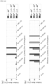
- FIG. 11 The relationship between the entering velocity of the flying object 31, the entering angle ⁇ shown in FIG. 10 and the success or failure of the entering is obtained and shown in FIG. 11 . It was confirmed that as shown in FIG. 11(b) , in the comparative example in which the guide rails 21a and 21b do not rotate, the entering success rate greatly decreases in the range of 35° ⁇ ⁇ ⁇ 40°, whereas as shown in FIG. 1 1(a) , the entering success rate was very high in the example using the passive guidance mechanism 10. It was confirmed that both the example using the passive guidance mechanism 10 and the comparative example had a very high entering success rate up to the entering angle ⁇ of 35°, and almost no difference was observed.
- FIG. 12 the relationship between the collision position y (distance from the center line of the opening at the initial position to the collision position with the guide rails 21a and 21b) shown in FIG. 10 , the entering angle ⁇ , and the failure rate of the entering is shown in FIG. 12 . It can be confirmed that as shown in FIG. 12(b) , in the comparative example, in the range of the collision position y of 15 mm to 60 mm, the failure rate was 100% when the entering angle ⁇ was 40° or more, and the failure rate was 50% or more when the entering angle ⁇ was 35° or more and less than 40°.
- the failure rate was 100% when the entering angle ⁇ was 35° or more and less than 40°.
- the failure rate was 100% when the entering angle ⁇ was 40° or more
- the failure rate was 0% when the entering angle ⁇ was 35° or more and less than 40°
- the entering angle range of the flying object 3 was wide.
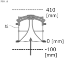
- the entering time was measured. As shown in FIG. 13 , the entering time was set to the time until the flying object passes through a position (the position where the flying object has left the sides of the other set of ends of the guide rails 21a and 21b) 410 mm from the opening on the sides of one set of ends of the guide rails 21a and 21b toward the sides of the other set of ends from the position 100 mm in front of the opening on the sides of one set of ends of the guide rails 21a and 21b. It was confirmed from the result of the measurement that the average entering time of those succeeded in entering was 0.65 seconds in the comparative example, whereas the average entering time of those succeeded in entering was 0.66 seconds in the examples using the passive guidance mechanism 10, and the entering time was almost the same.
- the average landing time (in 50 attempts) when the drone landed vertically on the ground from a height of 1.5 m was 4.94 seconds.
Landscapes
- Engineering & Computer Science (AREA)
- Aviation & Aerospace Engineering (AREA)
- Remote Sensing (AREA)
- Mechanical Engineering (AREA)
- Platform Screen Doors And Railroad Systems (AREA)
- Control Of Position, Course, Altitude, Or Attitude Of Moving Bodies (AREA)
Description
- The present invention relates to a flying object landing system.
- Conventionally, flying objects such as drones and unmanned aerial vehicles that can be flown by remote control or automatic control generally take off and land on a flat surface such as a dedicated landing platform, the ground, the upper surface of a vehicle, or the roof of a building (see, for example, Patent Literature 1 or 2).
-
Patent Literature 3 discloses unmanned aerial vehicle (UAV) positioning mechanisms for moving a UAV across a surface. The positioning mechanisms comprise a first guide assembly arranged opposite to a second guide assembly. A drive system is arranged to move the first guide assembly towards the second guide assembly and guide the UAV from a first position to a second position. - Patent Literature 4 discloses a
vertical carrier device 2 for refuse which causes arefuse storage body 5 to descend within a chute 21 and realizes simply such a configuration as to alleviate impact produced when the refuse storage body reaches the lower end of the shute. A chute 21 includes afirst chute 21a and asecond chute 21b arranged in the first chute in a non-fixed manner. A vertical carrier device has an opening/closing door 81 opening and closing a lower end opening of the second chute, and the opening/closing door is provided with a lower-part gate device which receives the refuse storage body when the refuse storage body descends within the first and second chutes, with the lower end opening of the second chute closed, and discharges the received refuse storage body to under the second chute by opening the lower-end opening of the second chute. The second chute is supported, while urging upward, so that the second chute is butted against the first chute, and acushioning support member 9 which absorbs impact produced when the refuse storage body is received by the opening/closing door is provided additionally. -
Patent Literature 5 discloses a landing device for a vertical lifting aircraft and a ship. The landing device comprises a lift-off platform, wherein a plurality of power devices used for driving the lift-off platform to ascend or descend are arranged on the lift-off platform, and a locking device for locking the aircraft is arranged on the lift-off platform; the locking device used for locking the aircraft is arranged on the lift-off platform; a power cable and a main probe pipe are arranged below the lift-off platform, and a main pull-off cable is arranged in the main probe pipe; and a damping landing frame is further arranged below the lift-off platform. The ship is provided with the landing device. According to the landing device, large impact on a deck when the aircraft lands on the deck canbe avoided, and the landing safety of the aircraft is improved. -
Patent Literature 6 discloses a landing gear (100) comprises a leg (110A, 110B, 110C), a rotating body (130A, 130B, 130C), and a housing (150). The leg (110A, 110B, 110C) makes contact with the landing surface at one end and moves linearly in the axial direction with the force received from the landing surface. The rotating body (130A, 130B, 130C) rotates by converting the linear motion of the leg (110A, 110B, 110C) into a rotary motion. The housing (150) accommodates the other end of the leg (110A, 110B, 110C) and rotatably holds the rotating body (130A, 130B, 130C). - Patent Literature 7 discloses a decoy can in which a sweetfish is smoothly guided to the interior and jumping-out of sweetfish from the interior is surely prevented. The decoy can 10 is equipped with a
subsidiary lid 41. Thesubsidiary lid 41 has an opening 50. In the decoy can 10, adoor 45 for opening and closing theopening 50 is installed. Thedoor 45 has a pair of door pieces 46 and 47. The each door piece 46 or 47 is rotatably supported by a supporting shaft 46 or 47. Each supporting shaft 52 or 53 is inclined at a prescribed angle and arranged so as to be symmetrical. The supporting shaft 53 is inclined to the upper surface of thesubsidiary lid 41. When thedoor 45 is opened, each door piece 46 or 47 is mutually remarkably separated to open the opening 50. - Patent Literature 8 discloses a rail recovery system for aircraft. The present invention's side-arm recovery system enables large Unmanned Aircraft Systems (UASs) to operate from small vessels or from ground sites with a minimal footprint. The side-arm recovery system allows arresting an UAS independent of a runway. On the ground or on a ship, the system makes use of a specialized crane system that includes capture and energy absorption devices. A fuselage-mounted top hook snags a horizontal cable and the arresting forces act in the plane of symmetry through the central structure of the UAS. After the capture energy is absorbed, the recovery system safely lowers the aerial vehicle to a ground handling cart. The same system can be combined into a launcher and retriever system which further reduces the footprint by eliminating the need for a separate launcher.
-
- Patent Literature 1:
JP-A-2019-089461 - Patent Literature 2:
JP-A-2018-190362 - Patent Literature 3:
WO 2019/055685 A1 - Patent Literature 4:
JP 2014 144829 A - Patent Literature 5:
CN 110 386 257 A - Patent Literature 6:
JP 2019 022098 A - Patent Literature 7:
JP 2007 124945 A - Patent Literature 8:
US 2013/082137 A1 - However, in a general flying object that takes off and lands on a flat surface as described in
Patent Literatures 1 and 2, it is necessary to reduce the thrust of a propeller or the like when landing, so that it is difficult to deal with disturbances and there is also the problem of the ground effect. Therefore, there is a problem that the control tends to be unstable and it is difficult to quickly guide the flying object to a desired position and land the flying object. - The present invention has been made in view of such a problem, and an object thereof is to provide a flying object landing system that enables smooth guiding to and landing at a desired position.
- In order to achieve the above object, a flying object landing system according to the present invention includes a pair of guide rails arranged side by side with a space therebetween and provided so that the space increases toward one set of tips of the guide rails, wherein one guide rail is supported so as to be rotatable about a first shaft extending in a direction perpendicular to a plane including the guide rails, at or near the tip thereof, and the other guide rail is supported so as to be rotatable about a second shaft extending in a direction perpendicular to the plane including the guide rails, at or near the tip thereof; a flying object having a suspension portion provided on an upper part so as to be inserted between the guide rails from sides of the one set of tips of the guide rails; and a landing means arranged on the sides of the other set of tips of the guide rails and provided so as to be able to land the flying object guided from sides of the one set of tips of the guide rails to the sides of the other set of tips through the suspension portion between the guide rails.
- In the flying object landing system according to the present invention, when a guiding target object collides with the inside of one guide rail when the guiding target object enters between the guide rails from sides of one set of tips of the guide rails, since one guide rail rotates toward the outer side around the first shaft, the angle between the traveling direction of the guiding target object and one guide rail can be reduced. Further, when the guiding target object collides with the inside of the other guide rail, since the other guide rail rotates toward the outer side around the second shaft, the angle between the traveling direction of the guiding target object and the other guide rail can be reduced. As a result, even if the guiding target object collides with each of the guide rails, the guiding target object can easily enter from sides of one set of tips of the guide rails toward the sides of the other set of tips without being bounced back to the side opposite to the entering direction. In this way, the passive guidance mechanism according to the present invention can smoothly guide the guiding target object to a desired position on the sides of the other set of tips of the guide rails.
- In the flying object landing system according to the present invention, since the guide rails are provided so that the space between the guide rails increases toward one set of tips, the guiding target object can easily enter between the guide rails from sides of one set of tips of the guide rails. The guide rails may have any shape as long as the space between the guide rails increases toward one set of tips of the guide rails. The guide rails may have a linear shape so that one set of tips of the guide rails form a smooth curve and the other set of tips are parallel to each other. One set of tips may have a linear shape and the entire guide rail may have a linear shape. The guide rails may be arranged at intervals in the vertical direction, or may be arranged at intervals in the horizontal direction.
- The flying object landing system according to the present invention may be configured to guide a moving object to a desired position, or may be configured to move itself and guide a stationary object to a desired position. The passive guidance mechanism according to the present invention can be used, for example, as a guidance mechanism for landing a flying object at a desired position, a robot arm or a gripper for capturing and gripping an object.
- In the flying object landing system according to the present invention, it is preferable that the one guide rail and the other guide rail are provided so as to be rotatable in a forward direction and a reverse direction in a range of predetermined rotation angles about the first shaft and the second shaft, respectively, from an initial position where the guide rails are arranged symmetrically with respect to a predetermined plane. In this case, the range of rotation angles of the first shaft and the second shaft can limit the range of movement of the other set of tips of the guide rails, and the guide range can be limited to a desired range.
- In the flying object landing system according to the present invention, it is preferable that the guide rails are configured to be urged toward the initial position. In this case, the rotationally moved guide rails can always be returned to the initial position. Therefore, the guiding target object can be moved to an intermediate position of each of the guide rails at the initial position, and the guide range can be narrowed.
- The flying object landing system according to the present invention may include a damper for absorbing a rotational force of the one guide rail and the rotational force of the other guide rail when the one guide rail rotates from the initial position to a side opposite to the other guide rail and when the other guide rail rotates from the initial position to a side opposite to the one guide rail. In this case, the damper can absorb the impact of the guiding target object that collides with the guide rails, and can prevent damage to the guide rails and the guiding target object. Further, it is possible to absorb the energy in the collision direction of the guiding target object and suppress the bounce, so that the guiding target object can easily enter from the sides of one set of tips of the guide rails toward the sides of the other set of tips.
- In the flying object landing system according to the present invention, it is preferable that the guide rails are connected to each other so that the rotation angle of the one guide rail about the first shaft from the initial position is equal to the rotation angle of the other guide rail about the second shaft from the initial position. In this case, when the guiding target object collides with one guide rail, one guide rail rotates toward the outer side and the other guide rail rotates toward the inner side, so that the guiding target object colliding with one guide rail can immediately collide with the other guide rail side and the guide rails can rotate toward the opposite sides. Similarly, when the guiding target object collides with the other guide rail, the other guide rail rotates toward the outer side and one guide rail rotates toward the inner side, so that the guiding target object colliding with the other guide rail can immediately collide with one guide rail side and the guide rails can rotate toward the opposite sides. As a result, the guiding target object can be gradually moved to an intermediate position of each of the guide rails at the initial position while colliding with the guide rails, and the guide range can be narrowed.
- In the flying object landing system according to the present invention, it is preferable that it includes a connecting member that connects the one guide rail and the other guide rail, the connecting member has one end connected the one guide rail so as to be rotatable about a third shaft perpendicular to the plane including the guide rails and has the other end connected to the other guide rail so as to be rotatable about a fourth shaft perpendicular to the plane including the guide rails, and the first shaft, the second shaft, the third shaft, and the fourth shaft form a four-node link mechanism composed of rotating pairs, and a line connecting the third shaft and the fourth shaft has the same length as and moves in parallel to a line connecting the first shaft and the second shaft. Also in this case, the guiding target object can be gradually moved to an intermediate position of each of the guide rails at the initial position while colliding with the guide rails, and the guide range can be narrowed.
- In the flying object landing system according to the present invention, it is preferable that the connecting member is arranged at a predetermined distance in a vertical direction from the plane including the guide rails. In this case, it is possible to prevent the guiding target object passing between the guide rails from hitting the connecting member.
- The flying object landing system according to the present invention preferably has a connection support member that supports the connecting member so as to be movable in relation to the guide rails. In this case, the guide rails and the connecting member can be stably rotated or moved.
- A flying object landing system according to the present invention; the landing means is arranged on the extension direction of the sides of the other set of tips of the guide rails.
- The flying object landing system according to the present invention can land a flying object as follows. That is, the flying object is made to fly from the sides of one set of tips of the guide rails toward the lower sides of the guide rails, and the suspension portion provided on the upper part of the flying object is inserted between the guide rails from the sides of one set of tips of the guide rails. At this time, the passive guidance mechanism can smoothly guide the flying object to the sides of the other set of tips of the guide rails, and the flying object can be landed by the landing means.
- In the flying object landing system according to the present invention, the influence of the ground effect can be made almost negligible by arranging the guide rails so that a sufficient space is provided under the flying object. In addition, since there is almost no influence of the ground effect, the flying object can land stably even in a relatively narrow space. In the flying object landing system according to the present invention, the guide rails may be installed in any place as long as a space can be provided at least on the lower side and in the extension direction on one end side. The guide rails may be installed on the ceiling or under the eaves of a factory, a house, a building, or the like, or may be suspended by a crane or the like.
- In the flying object landing system according to the present invention, it is preferable that the landing means has a pair of landing rails, and is configured so that the suspension portion of the flying object guided to the sides of the other set of tips of the guide rails is guided between the landing rails and the flying object can be suspended at a predetermined position of the landing rails with the suspension portion inserted between the landing rails.
- When the landing rails are provided, by inserting the suspension portion between the landing rails, the flying object can be easily moved to the landing position along the landing rails by only the urging force of the flying object at the time of insertion, or by applying force from the sides of one set of ends of the landing rails toward the sides of the other set of ends to the flying object. Therefore, after the suspension portion is inserted between the landing rails, fine flight control is not required, and in some cases, it is possible to stop the propulsion means such as the propeller of the flying object.
- In this case, the landing position of the landing rails may be a predetermined point, or may be a predetermined length range along the length direction of the landing rails. The flying object does not necessarily have to stop at the landing position. In this case, for example, the flying object landing system can be suitably used when carrying luggage or the like attached to the lower part of the flying object. When the flying object is suspended at the landing position, since there is a space under the flying object, it is easy to attach luggage to the lower part of the flying object and to unload the luggage attached to the lower part of the flying object. At this time, for example, by installing a belt conveyor under the flying object suspended at the landing position, the luggage being unloaded from the flying objects coming one after another can be conveyed by the belt conveyor, and the luggage being conveyed by the belt conveyor can be sequentially attached to the lower part of the flying object and transported individually.
- According to the present invention, it is possible to provide a flying object landing system that enables smooth guiding to and landing at a desired position.
-
-
FIG. 1 is a perspective view showing a passive guidance mechanism of the flying object landing system according to an embodiment of the present invention. -
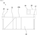
FIG. 2 is a front view showing the passive guidance mechanism of the flying object landing system according to the embodiment of the present invention. -
FIG. 3 is a right side view showing the passive guidance mechanism of the flying object landing system according to the embodiment of the present invention. -
FIG. 4 is a plan view showing the passive guidance mechanism of the flying object landing system according to the embodiment of the present invention. -
FIG. 5 is a plan view showing a state in which guide rails of the passive guidance mechanism of the flying object landing system according to the embodiment of the present invention are rotated. -
FIG. 6 is a perspective view showing a passive guidance mechanism and a flying object landing system according to an embodiment of the present invention. -
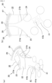
FIG. 7 includes (a) a perspective view and (b) a plan view showing a state in which a flying object flies toward the guide rails of the flying object landing system according to the embodiment of the present invention. -
FIG. 8 includes (a) a perspective view and (b) a plan view showing a state in which a flying object is inserted between the guide rails of the flying object landing system according to the embodiment of the present invention. -
FIG. 9 includes (a) a perspective view and (b) a plan view showing a state in which a flying object is guided to the sides of the other set of tips of the guide rails of the flying object landing system according to the embodiment of the present invention. -
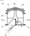
FIG. 10 is a plan view showing a test method for an entering test of a flying object in the flying object landing system according to the embodiment of the present invention. -
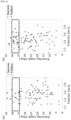
FIG. 11 is a graph showing a relationship between an entering velocity, an entering angle θ, and success or failure of entering in the flying object entering test shown inFIG. 10 , of (a) the flying object landing system of the embodiment of the present invention and (b) a comparative example in which guide rails do not rotate. -
FIG. 12 is a graph showing a relationship between a collision position y, an entering angle θ, and a failure rate of entering in the flying object entering test shown inFIG. 10 , of (a) the flying object landing system of the embodiment of the present invention and (b) a comparative example in which guide rails do not rotate. -
FIG. 13 is a plan view showing a method of measuring the entering time in the flying object entering test shown inFIG. 10 . - Hereinafter, embodiments of the present invention will be described with reference to the drawings.
-
FIGS. 1 to 6 show a passive guidance mechanism of the flying object landing system according to an embodiment of the present invention. - As shown in
FIGS. 1 to 6 , apassive guidance mechanism 10 has a pair ofrail members 11, arail support member 12, a connectingmember 13, and a connectingsupport member 14. - The pair of
rail members 11 has a pair ofguide rails entire guide rails - Each
rail member 11 has asurface member 22 extending in a direction perpendicular to a plane including theguide rails rail member 11 is provided so as to be rotatable about afirst shaft 23 extending in the direction perpendicular to the plane including theguide rails guide rail 21a. Theother rail member 11 is provided so as to be rotatable about asecond shaft 24 extending in the direction perpendicular to the plane including theguide rails guide rail 21b. Oneguide rail 21a and theother guide rail 21b are provided so as to be rotatable in the forward and reverse directions from an initial position where theguide rails guide rails - Each
rail member 11 has a first reinforcingportion 25a extending vertically toward the outer side from the other set of tips of theguide rails portion 25b extending from one set of tips to the first reinforcingportion 25a in parallel to the other set of linear tips, and a third reinforcingportion 25c extending parallel to the first reinforcingportion 25a from the vicinity of the center of the second reinforcingportion 25b toward theguide rails rail member 11 also has a reinforcing member for reinforcing thesurface member 22 and the like. - As shown in
FIG. 6 , therail support member 12 is provided so as to extend toward the outer side from one set of tips of theguide rails guide rails rail support member 12 supports theguide rails guide rails guide rails - As shown in
FIGS. 1 to 6 , the connectingmember 13 has a linear shape, and connects the connection position between the first reinforcingportion 25a and the second reinforcingportion 25b of onerail member 11 and the connection position between the first reinforcingportion 25a and the second reinforcingportion 25b of theother rail member 11. The connectingmember 13 has one end connected to oneguide rail 21a via the first reinforcingportion 25a and the second reinforcingportion 25b so as to be rotatable about athird shaft 26 perpendicular to the plane including theguide rails member 13 has the other end connected to theother guide rail 21b via the first reinforcingportion 25a and the second reinforcingportion 25b so as to be rotatable about afourth shaft 27 perpendicular to the plane including theguide rails member 13 is arranged at a predetermined distance from theguide rails surface member 22 in a direction perpendicular to the plane including theguide rails - The connecting
support member 14 is provided on the side of the connectingmember 13 opposite to theguide rails member 13 with respect to theguide rails support member 14 has aslide member 28 attached to the central portion of the connectingmember 13, and an arc-shapedsupport portion 29 provided so as to allow theslide member 28 to slide. The arc-shapedsupport portion 29 is provided along the trajectory of theslide member 28 when the connectingmember 13 moves with the rotation of theguide rails support member 14 is configured so that theslide member 28 slides smoothly. The connectingsupport member 14 is fixed to therail supporting member 12 and supports the connectingmember 13. - As shown in
FIGS. 4 and5 , in thepassive guidance mechanism 10, thefirst shaft 23, thesecond shaft 24, thethird shaft 26, and thefourth shaft 27 forms a four-node link mechanism composed of rotating pairs. In thepassive guidance mechanism 10, the line connecting thethird shaft 26 and thefourth shaft 27 has the same length as and moves in parallel to the line connecting thefirst shaft 23 and thesecond shaft 24. Thepassive guidance mechanism 10 is configured so that the rotation angle of oneguide rail 21a about thefirst shaft 23 from the initial position is equal to the rotation angle of theother guide rail 21b about thesecond shaft 24 from the initial position. - In the
passive guidance mechanism 10, the rotation range of theguide rails guide rails slide member 28 on the arc-shapedsupport portion 29. As a result, theguide rails first shaft 23 and thesecond shaft 24, respectively, within the defined range of the rotation angles from the initial position. - Next, the effects will be described.
- In the
passive guidance mechanism 10, when a guiding target object collides with the inside of oneguide rail 21a when the guiding target object enters between theguide rails guide rails guide rail 21a rotates toward the outer side around thefirst shaft 23, the angle between the traveling direction of the guiding target object and oneguide rail 21a can be reduced. Further, when the guiding target object collides with the inside of theother guide rail 21b, since theother guide rail 21b rotates toward the outer side around thesecond shaft 24, the angle between the traveling direction of the guiding target object and theother guide rail 21b can be reduced. As a result, even if the guiding target object collides with each of theguide rails guide rails - In the
passive guidance mechanism 10, when the guiding target object collides with oneguide rail 21a, oneguide rail 21a rotates toward the outer side and theother guide rail 21b rotates toward the inner side, so that the guiding target object colliding with oneguide rail 21a can immediately collide with theother guide rail 21b side and theguide rails other guide rail 21b, theother guide rail 21b rotates toward the outer side and oneguide rail 21a rotates toward the inner side, so that the guiding target object colliding with theother guide rail 21b can immediately collide with oneguide rail 21a side and theguide rails guide rails guide rails passive guidance mechanism 10 can smoothly guide the guiding target object to a desired position on the sides of the other set of tips of theguide rails - In the
passive guidance mechanism 10, since theguide rails guide rails guide rails guide rails member 13 is arranged at a predetermined distance from theguide rails guide rails member 13. Due to therail support member 12 and theconnection support member 14, theguide rails member 13 can be stably rotated and moved. - The
passive guidance mechanism 10 may be configured to guide a moving object to a desired position, or may be configured to move itself and guide a stationary object to a desired position. Thepassive guidance mechanism 10 can be used, for example, as a guidance mechanism for landing a flying object at a desired position, a robot arm or a gripper for capturing and gripping an object. - The
passive guidance mechanism 10 may be configured so that theguide rails guide rails guide rails - The
passive guidance mechanism 10 may include a damper for absorbing a rotational force of the oneguide rail 21a and the rotational force of theother guide rail 21b when the oneguide rail 21a rotates from the initial position to a side opposite to theother guide rail 21b and when theother guide rail 21b rotates from the initial position to a side opposite to the oneguide rail 21a. In this case, the damper can absorb the impact of the guiding target object that collides with theguide rails guide rails guide rails -
FIGS. 6 to 13 show a flying object landing system according to an embodiment of the present invention. - As shown in
FIGS. 6 to 9 , a flyingobject landing system 30 includes a flyingobject 31, thepassive guidance mechanism 10, and a landing means 32. - The flying
object body 31 has asuspension portion 41 provided at the upper part so as to extend upward. Thesuspension portion 41 has anarm 41a provided so as to extend upward from the flyingobject 31 and anengagement portion 41b provided at the tip of thearm 41a. Theengagement portion 41b has a shape that it is elongated along the traveling direction of the flyingobject 31, and the tip in the traveling direction is sharp. In a specific example, the flyingobject 31 is a drone, but may be any flyable object such as an aerial vehicle. The flyingobject 31 may be able to fly by remote control or may be able to fly by automatic control. - The
passive guidance mechanism 10 is provided so that thesuspension portion 41 of the flyingobject 31 can be inserted between theguide rails guide rails passive guidance mechanism 10 is provided so that the flyingobject 31 having thesuspension portion 41 inserted between theguide rails guide rails - As shown in
FIG. 6 , the landing means 32 has a pair of landing rails 42. The landing rails 42 are arranged side by side with a space between theguide rails guide rails guide rails guide rails guide rails suspension portion 41 of the flyingobject 31 guided to the sides of the other set of tips of theguide rails object 31 can be suspended and landed at a predetermined position of the landing rails 42 with thesuspension portion 41 inserted between the landing rails 42. - In a specific example, the
guide rails guide rails - Next, the effects will be described.
- The flying
object landing system 30 can land the flyingobject 31 as follows. That is, as shown inFIG. 7 , the flyingobject 31 is made to fly from the sides of one set of tips of theguide rails guide rails FIG. 8 , thesuspension portion 41 provided on the upper part of the flyingobject 31 is inserted between theguide rails guide rails engagement portion 41b of the flyingobject 31 has a shape in which the tip is sharpened in the traveling direction, the flyingobject 31 can be easily inserted between theguide rails FIG. 9 , thepassive guidance mechanism 10 gradually brings thesuspension portion 41 of the flyingobject 31 to an intermediate position of each of theguide rails guide rails object 31 can be smoothly guided to the sides of the other set of tips of theguide rails - The flying
object landing system 30 can guide thesuspension 41 of the flyingobject 31 guided from between theguide rails guide rails object 31. In the flyingobject landing system 30, the flyingobject 31 can be easily moved to the landing position along the landing rails 42 by only the urging force of the flyingobject 31 when thesuspension portion 41 of the flyingobject 31 is inserted between the landing rails 42, or by applying force from the sides of one set of ends of the landing rails 42 toward the other set of ends to the flyingobject 31. Therefore, after thesuspension portion 41 is inserted between the landing rails 42, fine flight control is not required, and in some cases, it is possible to stop the propulsion means such as the propeller of the flyingobject 31. - In the flying
object landing system 30, the influence of the ground effect can be made almost negligible by arranging theguide rails object 31. In addition, since there is almost no influence of the ground effect, the flyingobject 31 can land stably even in a relatively narrow space. - The flying
object landing system 30 can be suitably used when carrying luggage or the like attached to the lower part of the flyingobject 31. When the flyingobject 31 is suspended at the landing position, since there is a space under the flyingobject 31, it is easy to attach luggage to the lower part of the flyingobject 31 and to unload the luggage attached to the lower part of the flyingobject 31. At this time, for example, by installing a belt conveyor under the flyingobject 31 suspended at the landing position, the luggage being unloaded from the flying objects 31 coming one after another can be conveyed by the belt conveyor, and the luggage being conveyed by the belt conveyor can be sequentially attached to the lower part of the flyingobject 31 and transported individually. - The landing position of the landing rails 42 may be a predetermined point, or may be a predetermined length range along the length direction of the landing rails 42. The flying
object 31 does not necessarily have to stop at the landing position. Further, the landing rails 42 may be configured so that the flyingobject 31 can take off from the other set of ends on the side opposite to theguide rails object 31 can smoothly take off by moving the flyingobject 31 from the suspended state at the landing position toward the sides of the other set of ends of the landing rails 42. - Using the flying
object landing system 30 shown inFIGS. 6 to 9 , an entering test was conducted in which the flyingobject 31 was guided between the landing rails 42. In the test, as shown inFIG. 10 , the flyingobject 31 was made to enter from the sides of one set of ends of theguide rails 21b 100 times at a random angle and velocity, and the trajectory was recorded by a motion capture system (trade name: "OptiTrack"). For comparison, an entering test was conducted in the same manner in a state where theguide rails first shaft 23, thesecond shaft 24, thethird shaft 26, and thefourth shaft 27 do not rotate. - In the test, as the flying
object 31, a drone ("Mavic Air" manufactured by DJI) having asuspension portion 41 having a 180 mmlong arm 41a and anengagement portion 41b attached to the upper part was used. The drone is 168 mm in length, 184 mm in width, and 64 mm in height, and weighs 430 g, and the flyingobject 31 weighs 501.8 g. Further, as thepassive guidance mechanism 10, a mechanism was used in which theguide rails portion 25a, the second reinforcingportion 25b, the third reinforcingportion 25c, the connectingmember 13, and the connectingsupport member 14 are manufactured by a 3D printer using acrylic resin and thesurface member 22 is formed of a PET plate having a thickness of 1 mm. In thepassive guidance mechanism 10, the opening width on the sides of one set of ends of theguide rails guide rails guide rails surface member 22 is 112 mm, the opening angle at one set of ends of theguide rails rail members 11 is 120 g. - The relationship between the entering velocity of the flying
object 31, the entering angle θ shown inFIG. 10 and the success or failure of the entering is obtained and shown inFIG. 11 . It was confirmed that as shown inFIG. 11(b) , in the comparative example in which theguide rails FIG. 1 1(a) , the entering success rate was very high in the example using thepassive guidance mechanism 10. It was confirmed that both the example using thepassive guidance mechanism 10 and the comparative example had a very high entering success rate up to the entering angle θ of 35°, and almost no difference was observed. - Next, the relationship between the collision position y (distance from the center line of the opening at the initial position to the collision position with the
guide rails FIG. 10 , the entering angle θ, and the failure rate of the entering is shown inFIG. 12 . It can be confirmed that as shown inFIG. 12(b) , in the comparative example, in the range of the collision position y of 15 mm to 60 mm, the failure rate was 100% when the entering angle θ was 40° or more, and the failure rate was 50% or more when the entering angle θ was 35° or more and less than 40°. It was also confirmed that in the range of the collision position y of 60 mm to 90 mm, the failure rate was 100% when the entering angle θ was 35° or more and less than 40°. In contrast, as shown inFIG. 12(a) , it was confirmed that in the example using thepassive guidance mechanism 10, in the range of the collision position y of 30 mm to 60 mm, the failure rate was 100% when the entering angle θ was 40° or more, whereas in the range of the collision position y of 15 mm to 90 mm, the failure rate was 0% when the entering angle θ was 35° or more and less than 40°, and the entering angle range of the flyingobject 3 was wide. Among the examples using thepassive guidance mechanism 10 shown inFIG. 12(a) , a failure example was observed when the collision position y was in the range of 15 mm to 45 mm and the entering angle θ was less than 30°. However, in these failure examples, the flyingobject 31 that collided with theguide rails - Next, the entering time was measured. As shown in
FIG. 13 , the entering time was set to the time until the flying object passes through a position (the position where the flying object has left the sides of the other set of ends of theguide rails guide rails position 100 mm in front of the opening on the sides of one set of ends of theguide rails passive guidance mechanism 10, and the entering time was almost the same. The average landing time (in 50 attempts) when the drone landed vertically on the ground from a height of 1.5 m was 4.94 seconds. -
- 10: Passive guidance mechanism
- 11: Rail member
- 21a, 21b: Guide rail
- 22: Surface member
- 23: First shaft
- 24: Second shaft
- 25a: First reinforcing portion
- 25b: Second reinforcing portion
- 25c: Third reinforcing portion
- 12: Rail support member
- 13: Connecting member
- 26: Third shaft
- 27: Fourth shaft
- 14: Connection support member
- 28: Slide member
- 29: Arc-shaped support portion
- 30: Flying object landing system
- 31: flying object
- 41: Suspension portion
- 41a: Arm
- 41b: Engagement portion
- 32: Landing means
- 42: Landing rail
Claims (10)
- A flying object landing system (30) comprising:a passive guidance mechanism (10) having a pair of guide rails (21a, 21b) arranged side by side with a space therebetween and provided so that the space increases toward one set of tips of the guide rails (21a, 21b), whereinone guide rail (21a) is supported so as to be rotatable about a first shaft (23) extending in a direction perpendicular to a plane including the guide rails (21a, 21b), at or near the tip thereof, andthe other guide rail (21b) is supported so as to be rotatable about a second shaft (24) extending in a direction perpendicular to the plane including the guide rails (21a, 21b), at or near the tip thereof;a flying object (31) having a suspension portion (41) provided on an upper part so as to be inserted between the guide rails (21a, 21b) from sides of the one set of tips of the guide rails (21a, 21b); anda landing means (32) arranged on the sides of the other set of tips of the guide rails (21a, 21b) and provided so as to be able to land the flying object (31) guided from sides of the one set of tips of the guide rails (21a, 21b) to the sides of the other set of tips through the suspension portion (41) between the guide rails (21a, 21b).
- The flying object landing system (30) according to claim 1, wherein
the one guide rail (21a) and the other guide rail (21b) are provided so as to be rotatable in a forward direction and a reverse direction in a range of predetermined rotation angles about the first shaft (23) and the second shaft (24), respectively, from an initial position where the guide rails (21a, 21b) are arranged symmetrically with respect to a predetermined plane. - The flying object landing system (30) according to claim 2, wherein
the guide rails (21a, 21b) are configured to be urged toward the initial position. - The flying object landing system (30) according to claim 2 or 3, further comprising:
a damper for absorbing a rotational force of the one guide rail (21a) and the rotational force of the other guide rail (21b) when the one guide rail (21a) rotates from the initial position to a side opposite to the other guide rail (21b) and when the other guide rail (21b) rotates from the initial position to a side opposite to the one guide rail (21a). - The flying object landing system (30) according to any one of claims 2 to 4, wherein
the guide rails (21a, 21b) are connected to each other so that the rotation angle of the one guide rail (21a) about the first shaft (23) from the initial position is equal to the rotation angle of the other guide rail (21b) about the second shaft (24) from the initial position. - The flying object landing system (30) according to any one of claims 1 to 5, further comprising:a connecting member (13) that connects the one guide rail (21a) and the other guide rail (21b), whereinthe connecting member (13) has one end connected the one guide rail (21a) so as to be rotatable about a third shaft (26) perpendicular to the plane including the guide rails (21a, 21b) and has the other end connected to the other guide rail (21b) so as to be rotatable about a fourth shaft (27) perpendicular to the plane including the guide rails (21a, 21b), andthe first shaft (23), the second shaft (24), the third shaft (26), and the fourth shaft (27) form a four-node link mechanism composed of rotating pairs, and a line connecting the third shaft (26) and the fourth shaft (27) has the same length as and moves in parallel to a line connecting the first shaft (23) and the second shaft (24).
- The flying object landing system (30) according to claim 6, wherein
the connecting member (13) is arranged at a predetermined distance in a vertical direction from the plane including the guide rails (21a, 21b). - The flying object landing system (30) according to claim 6 or 7, further comprising:
a connection support member (14) that supports the connecting member (13) so as to be movable in relation to the guide rails (21a, 21b). - The flying object landing system (30) according to claim 1, wherein the landing means (32) is arranged on the extension direction of the sides of the other set of tips of the guide rails (21a, 21b).
- The flying object landing system (30) according to claim 1 or 9, wherein
the landing means (32) has a pair of landing rails (42), and is configured so that the suspension portion (41) of the flying object (31) guided to the sides of the other set of tips of the guide rails (21a, 21b) is guided between the landing rails (42) and the flying object (31) can be suspended at a predetermined position of the landing rails (42) with the suspension portion (41) inserted between the landing rails (42).
Applications Claiming Priority (2)
| Application Number | Priority Date | Filing Date | Title |
|---|---|---|---|
| JP2020037383A JP7466890B2 (en) | 2020-03-05 | 2020-03-05 | Passive guidance mechanism and aircraft landing system |
| PCT/JP2021/003523 WO2021176914A1 (en) | 2020-03-05 | 2021-02-01 | Passive guidance mechanism and flying object landing system |
Publications (4)
| Publication Number | Publication Date |
|---|---|
| EP4116193A1 EP4116193A1 (en) | 2023-01-11 |
| EP4116193A4 EP4116193A4 (en) | 2023-08-02 |
| EP4116193C0 EP4116193C0 (en) | 2025-01-29 |
| EP4116193B1 true EP4116193B1 (en) | 2025-01-29 |
Family
ID=77614017
Family Applications (1)
| Application Number | Title | Priority Date | Filing Date |
|---|---|---|---|
| EP21764136.4A Active EP4116193B1 (en) | 2020-03-05 | 2021-02-01 | Passive guidance mechanism and flying object landing system |
Country Status (5)
| Country | Link |
|---|---|
| US (1) | US12065242B2 (en) |
| EP (1) | EP4116193B1 (en) |
| JP (1) | JP7466890B2 (en) |
| CN (1) | CN115210142B (en) |
| WO (1) | WO2021176914A1 (en) |
Families Citing this family (1)
| Publication number | Priority date | Publication date | Assignee | Title |
|---|---|---|---|---|
| JP6789558B1 (en) * | 2019-08-09 | 2020-11-25 | 国立大学法人東北大学 | Aircraft takeoff and landing system, air vehicle takeoff and landing equipment and air vehicle |
Family Cites Families (20)
| Publication number | Priority date | Publication date | Assignee | Title |
|---|---|---|---|---|
| JP4454564B2 (en) * | 2005-11-04 | 2010-04-21 | 株式会社シマノ | Fishing vessel |
| CN201343147Y (en) * | 2008-12-03 | 2009-11-11 | 北京航天发射技术研究所 | Emitting system for ejecting aircraft in pneumatic track |
| GB2486448B (en) * | 2010-12-15 | 2013-06-05 | Gh Dynamics Ltd | Aircraft propulsion system tilting mechanism |
| US9010683B2 (en) * | 2011-09-30 | 2015-04-21 | Aurora Flight Sciences Corporation | Rail recovery system for aircraft |
| WO2014014136A1 (en) * | 2012-07-17 | 2014-01-23 | 양후영 | Aircraft capable of takeoff/landing via the fuselage thereof, and takeoff/landing system for the aircraft |
| JP2014040186A (en) | 2012-08-22 | 2014-03-06 | Shoichi Sakamoto | Rotary takeoff-landing device |
| JP6116262B2 (en) | 2013-01-28 | 2017-04-19 | 新明和工業株式会社 | Garbage vertical conveyor |
| FR3016222B1 (en) * | 2014-01-03 | 2016-02-05 | Airbus Operations Sas | METHOD AND APPARATUS FOR VERTICAL GUIDANCE OF AN AIRCRAFT DURING AN APPROACH TO A LANDING TRACK ALONG A LATERAL APPROACH TRACK |
| CN204568057U (en) * | 2015-03-18 | 2015-08-19 | 兆利丰股份有限公司 | Propeller Aircraft Landing Positioning System |
| CN206494119U (en) | 2016-12-09 | 2017-09-15 | 佛山科学技术学院 | A kind of full-automatic connecting platform of unmanned plane |
| WO2018189251A1 (en) * | 2017-04-11 | 2018-10-18 | Ampyx Power B.V. | Launch and land system for a tethered aircraft |
| JP7083099B2 (en) | 2017-05-11 | 2022-06-10 | 大平電子株式会社 | Drone landing gear |
| JP6957251B2 (en) * | 2017-07-18 | 2021-11-02 | 東芝テック株式会社 | Wireless tag reader |
| GB201812471D0 (en) * | 2017-09-13 | 2018-09-12 | Flirtey Holdings Inc | Positioning mechanism |
| JP6832265B2 (en) * | 2017-10-05 | 2021-02-24 | 本田技研工業株式会社 | Flying object storage system |
| JP2019089461A (en) * | 2017-11-15 | 2019-06-13 | 株式会社ディーエイチシー | Drone port system |
| WO2019155854A1 (en) * | 2018-02-07 | 2019-08-15 | 国立大学法人大阪大学 | Multicopter system and method for transferring goods |
| JP7045691B2 (en) * | 2018-03-07 | 2022-04-01 | 株式会社イクシス | Suspended traveling device |
| CN208161056U (en) | 2018-04-14 | 2018-11-30 | 新疆石河子职业技术学院(石河子市技工学校) | A kind of physical education hurdles rack with safeguard protection |
| CN110386257B (en) * | 2018-07-30 | 2024-06-04 | 魏荣亮 | Ship landing device for vertical lifting aircraft and ship |
-
2020
- 2020-03-05 JP JP2020037383A patent/JP7466890B2/en active Active
-
2021
- 2021-02-01 EP EP21764136.4A patent/EP4116193B1/en active Active
- 2021-02-01 US US17/909,298 patent/US12065242B2/en active Active
- 2021-02-01 CN CN202180018810.8A patent/CN115210142B/en active Active
- 2021-02-01 WO PCT/JP2021/003523 patent/WO2021176914A1/en not_active Ceased
Also Published As
| Publication number | Publication date |
|---|---|
| EP4116193C0 (en) | 2025-01-29 |
| CN115210142A (en) | 2022-10-18 |
| US20230045539A1 (en) | 2023-02-09 |
| JP2021138274A (en) | 2021-09-16 |
| WO2021176914A1 (en) | 2021-09-10 |
| CN115210142B (en) | 2025-05-06 |
| EP4116193A4 (en) | 2023-08-02 |
| EP4116193A1 (en) | 2023-01-11 |
| US12065242B2 (en) | 2024-08-20 |
| JP7466890B2 (en) | 2024-04-15 |
Similar Documents
| Publication | Publication Date | Title |
|---|---|---|
| US10981671B2 (en) | Line capture devices for unmanned aircraft, and associated systems and methods | |
| US9896182B1 (en) | Systems and methods for maneuvering a package following in-flight release from an unmanned aerial vehicle (UAV) | |
| US7954758B2 (en) | Method and apparatus for retrieving a hovering aircraft | |
| EP4375200B1 (en) | Vertical air vehicle takeoff and landing stabilization apparatuses and methods | |
| EP3712075B1 (en) | Line capture devices for unmanned aircraft, and associated systems and methods | |
| US6264140B1 (en) | Method for retrieving a fixed-wing aircraft without a runway | |
| CN114560088B (en) | Aircraft, cargo arrival method, system, and program | |
| US20020100838A1 (en) | Method and apparatus for retrieving a flying object | |
| US12522353B2 (en) | Attachment sub-systems for vertically-stacked multicopters | |
| US12065242B2 (en) | Passive guidance mechanism and flying object landing system | |
| AU2015271974B2 (en) | Line capture devices for unmanned aircraft, and associated systems and methods |
Legal Events
| Date | Code | Title | Description |
|---|---|---|---|
| STAA | Information on the status of an ep patent application or granted ep patent |
Free format text: STATUS: THE INTERNATIONAL PUBLICATION HAS BEEN MADE |
|
| PUAI | Public reference made under article 153(3) epc to a published international application that has entered the european phase |
Free format text: ORIGINAL CODE: 0009012 |
|
| STAA | Information on the status of an ep patent application or granted ep patent |
Free format text: STATUS: REQUEST FOR EXAMINATION WAS MADE |
|
| 17P | Request for examination filed |
Effective date: 20220909 |
|
| AK | Designated contracting states |
Kind code of ref document: A1 Designated state(s): AL AT BE BG CH CY CZ DE DK EE ES FI FR GB GR HR HU IE IS IT LI LT LU LV MC MK MT NL NO PL PT RO RS SE SI SK SM TR |
|
| DAV | Request for validation of the european patent (deleted) | ||
| DAX | Request for extension of the european patent (deleted) | ||
| A4 | Supplementary search report drawn up and despatched |
Effective date: 20230703 |
|
| RIC1 | Information provided on ipc code assigned before grant |
Ipc: B64U 70/97 20230101ALI20230627BHEP Ipc: B64U 70/70 20230101ALI20230627BHEP Ipc: B64F 1/36 20170101ALI20230627BHEP Ipc: B64F 1/12 20060101ALI20230627BHEP Ipc: B64C 39/02 20230101AFI20230627BHEP |
|
| GRAP | Despatch of communication of intention to grant a patent |
Free format text: ORIGINAL CODE: EPIDOSNIGR1 |
|
| STAA | Information on the status of an ep patent application or granted ep patent |
Free format text: STATUS: GRANT OF PATENT IS INTENDED |
|
| RIC1 | Information provided on ipc code assigned before grant |
Ipc: B64U 70/95 20230101ALI20241105BHEP Ipc: B64F 1/12 20060101ALI20241105BHEP Ipc: B64F 1/36 20170101ALI20241105BHEP Ipc: B64U 70/70 20230101ALI20241105BHEP Ipc: B64U 70/97 20230101ALI20241105BHEP Ipc: B64C 39/02 20230101AFI20241105BHEP |
|
| GRAS | Grant fee paid |
Free format text: ORIGINAL CODE: EPIDOSNIGR3 |
|
| INTG | Intention to grant announced |
Effective date: 20241118 |
|
| GRAA | (expected) grant |
Free format text: ORIGINAL CODE: 0009210 |
|
| STAA | Information on the status of an ep patent application or granted ep patent |
Free format text: STATUS: THE PATENT HAS BEEN GRANTED |
|
| AK | Designated contracting states |
Kind code of ref document: B1 Designated state(s): AL AT BE BG CH CY CZ DE DK EE ES FI FR GB GR HR HU IE IS IT LI LT LU LV MC MK MT NL NO PL PT RO RS SE SI SK SM TR |
|
| REG | Reference to a national code |
Ref country code: GB Ref legal event code: FG4D |
|
| REG | Reference to a national code |
Ref country code: CH Ref legal event code: EP |
|
| REG | Reference to a national code |
Ref country code: DE Ref legal event code: R096 Ref document number: 602021025465 Country of ref document: DE |
|
| REG | Reference to a national code |
Ref country code: IE Ref legal event code: FG4D |
|
| U01 | Request for unitary effect filed |
Effective date: 20250224 |
|
| U07 | Unitary effect registered |
Designated state(s): AT BE BG DE DK EE FI FR IT LT LU LV MT NL PT RO SE SI Effective date: 20250228 |
|
| U20 | Renewal fee for the european patent with unitary effect paid |
Year of fee payment: 5 Effective date: 20250224 |
|
| PG25 | Lapsed in a contracting state [announced via postgrant information from national office to epo] |
Ref country code: RS Free format text: LAPSE BECAUSE OF FAILURE TO SUBMIT A TRANSLATION OF THE DESCRIPTION OR TO PAY THE FEE WITHIN THE PRESCRIBED TIME-LIMIT Effective date: 20250429 |
|
| PG25 | Lapsed in a contracting state [announced via postgrant information from national office to epo] |
Ref country code: PL Free format text: LAPSE BECAUSE OF FAILURE TO SUBMIT A TRANSLATION OF THE DESCRIPTION OR TO PAY THE FEE WITHIN THE PRESCRIBED TIME-LIMIT Effective date: 20250129 |
|
| PG25 | Lapsed in a contracting state [announced via postgrant information from national office to epo] |
Ref country code: ES Free format text: LAPSE BECAUSE OF FAILURE TO SUBMIT A TRANSLATION OF THE DESCRIPTION OR TO PAY THE FEE WITHIN THE PRESCRIBED TIME-LIMIT Effective date: 20250129 |
|
| PG25 | Lapsed in a contracting state [announced via postgrant information from national office to epo] |
Ref country code: IS Free format text: LAPSE BECAUSE OF FAILURE TO SUBMIT A TRANSLATION OF THE DESCRIPTION OR TO PAY THE FEE WITHIN THE PRESCRIBED TIME-LIMIT Effective date: 20250529 Ref country code: NO Free format text: LAPSE BECAUSE OF FAILURE TO SUBMIT A TRANSLATION OF THE DESCRIPTION OR TO PAY THE FEE WITHIN THE PRESCRIBED TIME-LIMIT Effective date: 20250429 |
|
| PG25 | Lapsed in a contracting state [announced via postgrant information from national office to epo] |
Ref country code: HR Free format text: LAPSE BECAUSE OF FAILURE TO SUBMIT A TRANSLATION OF THE DESCRIPTION OR TO PAY THE FEE WITHIN THE PRESCRIBED TIME-LIMIT Effective date: 20250129 |
|
| PG25 | Lapsed in a contracting state [announced via postgrant information from national office to epo] |
Ref country code: GR Free format text: LAPSE BECAUSE OF FAILURE TO SUBMIT A TRANSLATION OF THE DESCRIPTION OR TO PAY THE FEE WITHIN THE PRESCRIBED TIME-LIMIT Effective date: 20250430 |
|
| REG | Reference to a national code |
Ref country code: CH Ref legal event code: PL |
|
| PG25 | Lapsed in a contracting state [announced via postgrant information from national office to epo] |
Ref country code: SM Free format text: LAPSE BECAUSE OF FAILURE TO SUBMIT A TRANSLATION OF THE DESCRIPTION OR TO PAY THE FEE WITHIN THE PRESCRIBED TIME-LIMIT Effective date: 20250129 |
|
| PG25 | Lapsed in a contracting state [announced via postgrant information from national office to epo] |
Ref country code: MC Free format text: LAPSE BECAUSE OF FAILURE TO SUBMIT A TRANSLATION OF THE DESCRIPTION OR TO PAY THE FEE WITHIN THE PRESCRIBED TIME-LIMIT Effective date: 20250129 |
|
| PG25 | Lapsed in a contracting state [announced via postgrant information from national office to epo] |
Ref country code: CH Free format text: LAPSE BECAUSE OF NON-PAYMENT OF DUE FEES Effective date: 20250228 |
|
| PG25 | Lapsed in a contracting state [announced via postgrant information from national office to epo] |
Ref country code: CZ Free format text: LAPSE BECAUSE OF FAILURE TO SUBMIT A TRANSLATION OF THE DESCRIPTION OR TO PAY THE FEE WITHIN THE PRESCRIBED TIME-LIMIT Effective date: 20250129 |
|
| PG25 | Lapsed in a contracting state [announced via postgrant information from national office to epo] |
Ref country code: SK Free format text: LAPSE BECAUSE OF FAILURE TO SUBMIT A TRANSLATION OF THE DESCRIPTION OR TO PAY THE FEE WITHIN THE PRESCRIBED TIME-LIMIT Effective date: 20250129 |
|
| PLBE | No opposition filed within time limit |
Free format text: ORIGINAL CODE: 0009261 |
|
| STAA | Information on the status of an ep patent application or granted ep patent |
Free format text: STATUS: NO OPPOSITION FILED WITHIN TIME LIMIT |
|
| GBPC | Gb: european patent ceased through non-payment of renewal fee |
Effective date: 20250429 |
|
| 26N | No opposition filed |
Effective date: 20251030 |
|
| PG25 | Lapsed in a contracting state [announced via postgrant information from national office to epo] |
Ref country code: GB Free format text: LAPSE BECAUSE OF NON-PAYMENT OF DUE FEES Effective date: 20250429 |
|
| PG25 | Lapsed in a contracting state [announced via postgrant information from national office to epo] |
Ref country code: IE Free format text: LAPSE BECAUSE OF NON-PAYMENT OF DUE FEES Effective date: 20250201 |
|
| U20 | Renewal fee for the european patent with unitary effect paid |
Year of fee payment: 6 Effective date: 20260119 |