EP4116168A1 - Self-closing door assembly of a sliding door, toilet cabin for a railway vehicle, and self-closing door assembly kit - Google Patents
Self-closing door assembly of a sliding door, toilet cabin for a railway vehicle, and self-closing door assembly kit Download PDFInfo
- Publication number
- EP4116168A1 EP4116168A1 EP22182856.9A EP22182856A EP4116168A1 EP 4116168 A1 EP4116168 A1 EP 4116168A1 EP 22182856 A EP22182856 A EP 22182856A EP 4116168 A1 EP4116168 A1 EP 4116168A1
- Authority
- EP
- European Patent Office
- Prior art keywords
- sliding door
- self
- connecting element
- spring device
- closing
- Prior art date
- Legal status (The legal status is an assumption and is not a legal conclusion. Google has not performed a legal analysis and makes no representation as to the accuracy of the status listed.)
- Granted
Links
Images




Classifications
-
- B—PERFORMING OPERATIONS; TRANSPORTING
- B61—RAILWAYS
- B61D—BODY DETAILS OR KINDS OF RAILWAY VEHICLES
- B61D19/00—Door arrangements specially adapted for rail vehicles
- B61D19/003—Door arrangements specially adapted for rail vehicles characterised by the movements of the door
- B61D19/005—Door arrangements specially adapted for rail vehicles characterised by the movements of the door sliding
-
- B—PERFORMING OPERATIONS; TRANSPORTING
- B61—RAILWAYS
- B61D—BODY DETAILS OR KINDS OF RAILWAY VEHICLES
- B61D35/00—Sanitation
- B61D35/005—Toilet facilities
-
- B—PERFORMING OPERATIONS; TRANSPORTING
- B61—RAILWAYS
- B61D—BODY DETAILS OR KINDS OF RAILWAY VEHICLES
- B61D19/00—Door arrangements specially adapted for rail vehicles
- B61D19/02—Door arrangements specially adapted for rail vehicles for carriages
-
- B—PERFORMING OPERATIONS; TRANSPORTING
- B61—RAILWAYS
- B61D—BODY DETAILS OR KINDS OF RAILWAY VEHICLES
- B61D35/00—Sanitation
-
- E—FIXED CONSTRUCTIONS
- E05—LOCKS; KEYS; WINDOW OR DOOR FITTINGS; SAFES
- E05F—DEVICES FOR MOVING WINGS INTO OPEN OR CLOSED POSITION; CHECKS FOR WINGS; WING FITTINGS NOT OTHERWISE PROVIDED FOR, CONCERNED WITH THE FUNCTIONING OF THE WING
- E05F1/00—Closers or openers for wings, not otherwise provided for in this subclass
- E05F1/002—Closers or openers for wings, not otherwise provided for in this subclass controlled by automatically acting means
- E05F1/008—Closers or openers for wings, not otherwise provided for in this subclass controlled by automatically acting means by time control
-
- E—FIXED CONSTRUCTIONS
- E05—LOCKS; KEYS; WINDOW OR DOOR FITTINGS; SAFES
- E05F—DEVICES FOR MOVING WINGS INTO OPEN OR CLOSED POSITION; CHECKS FOR WINGS; WING FITTINGS NOT OTHERWISE PROVIDED FOR, CONCERNED WITH THE FUNCTIONING OF THE WING
- E05F1/00—Closers or openers for wings, not otherwise provided for in this subclass
- E05F1/08—Closers or openers for wings, not otherwise provided for in this subclass spring-actuated, e.g. for horizontally sliding wings
- E05F1/16—Closers or openers for wings, not otherwise provided for in this subclass spring-actuated, e.g. for horizontally sliding wings for sliding wings
-
- E—FIXED CONSTRUCTIONS
- E05—LOCKS; KEYS; WINDOW OR DOOR FITTINGS; SAFES
- E05F—DEVICES FOR MOVING WINGS INTO OPEN OR CLOSED POSITION; CHECKS FOR WINGS; WING FITTINGS NOT OTHERWISE PROVIDED FOR, CONCERNED WITH THE FUNCTIONING OF THE WING
- E05F3/00—Closers or openers with braking devices, e.g. checks; Construction of pneumatic or liquid braking devices
- E05F3/04—Closers or openers with braking devices, e.g. checks; Construction of pneumatic or liquid braking devices with liquid piston brakes
-
- E—FIXED CONSTRUCTIONS
- E05—LOCKS; KEYS; WINDOW OR DOOR FITTINGS; SAFES
- E05F—DEVICES FOR MOVING WINGS INTO OPEN OR CLOSED POSITION; CHECKS FOR WINGS; WING FITTINGS NOT OTHERWISE PROVIDED FOR, CONCERNED WITH THE FUNCTIONING OF THE WING
- E05F5/00—Braking devices, e.g. checks; Stops; Buffers
- E05F5/003—Braking devices, e.g. checks; Stops; Buffers for sliding wings
-
- E—FIXED CONSTRUCTIONS
- E05—LOCKS; KEYS; WINDOW OR DOOR FITTINGS; SAFES
- E05Y—INDEXING SCHEME ASSOCIATED WITH SUBCLASSES E05D AND E05F, RELATING TO CONSTRUCTION ELEMENTS, ELECTRIC CONTROL, POWER SUPPLY, POWER SIGNAL OR TRANSMISSION, USER INTERFACES, MOUNTING OR COUPLING, DETAILS, ACCESSORIES, AUXILIARY OPERATIONS NOT OTHERWISE PROVIDED FOR, APPLICATION THEREOF
- E05Y2900/00—Application of doors, windows, wings or fittings thereof
- E05Y2900/50—Application of doors, windows, wings or fittings thereof for vehicles
-
- E—FIXED CONSTRUCTIONS
- E05—LOCKS; KEYS; WINDOW OR DOOR FITTINGS; SAFES
- E05Y—INDEXING SCHEME ASSOCIATED WITH SUBCLASSES E05D AND E05F, RELATING TO CONSTRUCTION ELEMENTS, ELECTRIC CONTROL, POWER SUPPLY, POWER SIGNAL OR TRANSMISSION, USER INTERFACES, MOUNTING OR COUPLING, DETAILS, ACCESSORIES, AUXILIARY OPERATIONS NOT OTHERWISE PROVIDED FOR, APPLICATION THEREOF
- E05Y2900/00—Application of doors, windows, wings or fittings thereof
- E05Y2900/50—Application of doors, windows, wings or fittings thereof for vehicles
- E05Y2900/51—Application of doors, windows, wings or fittings thereof for vehicles for railway cars or mass transit vehicles
-
- E—FIXED CONSTRUCTIONS
- E05—LOCKS; KEYS; WINDOW OR DOOR FITTINGS; SAFES
- E05Y—INDEXING SCHEME ASSOCIATED WITH SUBCLASSES E05D AND E05F, RELATING TO CONSTRUCTION ELEMENTS, ELECTRIC CONTROL, POWER SUPPLY, POWER SIGNAL OR TRANSMISSION, USER INTERFACES, MOUNTING OR COUPLING, DETAILS, ACCESSORIES, AUXILIARY OPERATIONS NOT OTHERWISE PROVIDED FOR, APPLICATION THEREOF
- E05Y2900/00—Application of doors, windows, wings or fittings thereof
- E05Y2900/50—Application of doors, windows, wings or fittings thereof for vehicles
- E05Y2900/53—Type of wing
- E05Y2900/531—Doors
Definitions
- Embodiments of the present invention relate to a self-closing door assembly for a curved sliding door such as a curved sliding door for a toilet cabin of a railway vehicle. Further embodiments pertain to a toilet cabin for railway vehicles having a self-closing door assembly for the curved sliding door of the toilet cabin. Further embodiments of the present invention pertain to a self-closing door assembly kit for retrofitting manual sliding doors particularly curved sliding doors moving along a predefined curved path between an open position and a closed position.
- railway vehicles for public mass transport are equipped with facilities such as toilets to improve passengers' comfort.
- the space in a railway vehicle is often limited so that the facilities are configured so as to use the available space most efficiently.
- toilet compartments are designed to have, at least partially, walls with a curved or arc-shaped (shape of circular segment) outer contour.
- the door leaf of a curved sliding door used to close the toilet compartment has also a curved or arc-shape so that the door can be moved along a circular path following the curved contour of the toilet compartment.
- Modern railway vehicles are often equipped with fully automatic doors which can be operated by pressing a button by which an opening and closing mechanism is actuated. While those automatic doors are very convenient, they require extra equipment such as an electrical motor or other suitable electromechanical components which not only contribute to the total weight of the railway vehicle but may be prone to failure and require additional maintenance.
- CN 112027869 A and CN 210558803 U describe a self-closing structure of an elevator landing door.
- KR 102001453 B1 describes a door assembly of a toilet compartment for handicapped persons using electromechanical components.
- CN 109693992 A describes an electromagnetic type landing door self-closing system.
- CN 108974027 A discloses a double linkage sliding door device for a toilet compartment of a railway vehicle.
- CN 206049681 U describes another self-closing mechanism for railway vehicles.
- EP 3259166 B1 describes a cabin with a rotatable cabin door for a vehicle.
- CN 204237414 U describes a self-closing door assembly for an elevator.
- KR 101407381 B1 describes an automatically closing sliding door.
- CN 102296901 B discloses a device for automatically opening and closing a cabin door.
- EP 1409824 A1 discloses a closing sequence control device for a self-closing door.
- DE 3934269 A1 discloses a self-closing device for a door or window.
- a self-closing door assembly of a curved sliding door includes a curved sliding door movable along a predefined curved path between an open position and a closed position, and a closing mechanism.
- the closing mechanism includes a spring device to move the sliding door into the closed position; a connecting element having a first end connected to the spring device and a second end connected to the sliding door; a plurality of diverter elements arranged along the curved path of the sliding door for guiding the connecting element along the curved path; and a damping element in engagement with the connecting element to limit movement of the connecting element when the connecting element is pulled by the spring device for moving the sliding door into the closed position.
- the spring device is tensioned, through transmission by the connecting element, when the sliding door towards the open position.
- the self-closing door assembly is composed of few reliable mechanical elements and allows retrofitting of existing manual curved sliding doors.
- a challenge for curved sliding doors moving along a predefined curved path is that the door leaf of the sliding door rotates about a vertical axis which is off-set to the door leaf.
- a simple push-pull mechanism would not be a suitable choice for curved sliding doors.
- the present invention overcomes these drawbacks by using a connecting element which connects the spring device with the sliding door.
- the diverter elements are arranged along the moving path of the curved sliding door and guide the connecting element so that the connecting element can follow the predefined curved path along which the sliding door moves.
- the connecting element can therefore always pull the sliding door tangentially along the predefined curved path maximising the force transmitted from the spring device on the sliding door when closing the sliding door.
- the directional operation of the spring device does not need to be aligned with any tangential direction of the predefined curved path. This provides more freedom for arranging the spring device.
- the connecting element is typically bendable so that, when it moves together with the door leaf, it is bent to follow the curved path.
- the diverter elements of the plurality of diverter elements can be arranged separately along the curved path.
- a diverter element of the plurality of diverter elements can be arranged distant to another diverter element of the plurality of diverter elements, in particular distant to each other diverter element of the plurality of diverter elements.
- all diverter elements are arranged spaced from each other.
- a gap is arranged between a diverter element and another diverter element, particularly a consecutive diverter element of the plurality of diverter elements.
- a length of the gap along the direction of the curved path can be larger than an extension of a diverter element along the curved path.
- the length of the gap can be larger than a diameter of the diverter element of the plurality of diverter elements.
- the plurality of diverter elements can be arranged equally distributed.
- curved path and a curved sliding door basically any shape of a curve is meant.
- the curved path and the curved sliding door are specifically arc-shaped (circularly arc-shaped), i.e. they correspond to a segment of a circle. In typical embodiments, the segment is not more than a 90-degree circular arc.
- the driving element for closing the sliding door is provided by the spring device which is tensioned when the sliding door is manually opened by user.
- the connecting element pulls on the spring device and tensions a spring arranged within the spring device. If the user does not actively keep the sliding door open or block the sliding door, or if the door is not blocked by other means, the energy stored in the spring device results in a retracting force pulling the sliding door back into its closed position.
- the spring device acts as a mechanical energy storage means which stores tension energy supplied to the spring device, particularly to a spring of the spring device, when the sliding door is manually opened. The stored tension energy is used to close the sliding door.
- the damping element can limit the maximum speed at which the sliding doors opens.
- a damping element with asymmetric action is used.
- the damping element may damp the closing movement of the sliding door more than the opening movement to allow the user to open the door more quickly.
- the maximum speed at which the sliding door can be opened may also be limited for safety reasons.
- the damping element can be arranged and configured to restrict the speed at which the sliding door opens.
- the damping element can decelerate the opening of the sliding door.
- the damping element can be arranged and configured for a smooth opening of the sliding door.
- the damping element can be arranged and configured to limit the speed of the sliding door during the movement of the door from its closed position to its open position. According to an embodiment, the damping element can be arranged and configured to restrict the speed at which the sliding door opens less than the speed at which the sliding door closes.
- the self-closing door assembly described herein is particularly suitable for manually operated doors, i.e. for non-automatic doors which are not driven, or not partly driven, by electromechanical drive units. Moreover, the self-closing door assembly is easy to install, allows great flexibility for adapting to local geometries and designs, and is a cost-efficient solution. Specifically, for opening of the sliding door, manual operation, i.e. manual moving of the door by a user or passenger, is needed. The closing of the sliding door occurs automatically in the sense that the spring device brings the sliding door back into its closed position. The sliding door can also be closed manually.
- the self-closing door assembly is therefore autonomous as it does not require supply of electrical energy. It is semi-automatic (as it closes the sliding door automatically but requires manual work to open it) and fully mechanical as the closing can occur by action of the closing mechanism without requiring any electromechanical component and supply of electrical energy.
- the self-closing door assembly described herein is particularly of advantage for curved sliding doors such as arc-shaped doors as diverter elements are used to guide the connecting element virtually along any curved path.
- the spring device may include a housing for accommodating a spring arranged within the housing.
- the housing may include fastening means for attaching the spring device to structural elements such as a ceiling or a wall.
- the spring device includes a spiral spring (torsion spring) for winding up the connecting element, which may be bendable or flexible but inelastic.
- the spring device may be a spring rope pulley.
- a spiral spring allows for a compact design of the spring device.
- the spring force can be easily adjusted by the number of windings of the spiral spring. For example, if the spiral spring is provided with a higher number of windings and is pretensioned, the spring force can be kept in a linear range of the spring regardless of whether the door is fully opened or closed. In fact, when using a higher number of windings, the spring force can be kept approximately constant over the operating range defined by the maximum opening range of the sliding door.
- the spring device further includes an inner guiding element arranged in and extending along the outer tube, wherein the helical spring is wound around the inner guiding element and between the inner guiding element and the outer tube.
- Inner and outer tube cooperate together for guiding the helical spring and to prevent the helical spring from disengaging or deforming when expanding or contracting.
- the inner and outer tubes may be arranged coaxially relative to each other.
- the connecting element is flexible and inelastic.
- the connecting element may be an inelastic rope, a chain, a cable, or a belt.
- the connecting element is preferably not elastic so that the connecting element can immediately transmit the force exerted from the spring device, i.e. from the spring of the spring device, to the sliding door or, when the sliding door is manually opened, from the sliding door to the spring device.
- the connecting element is thus, unlike the spring device, not an energy storage means.
- the connecting element can also be described as being limp. The flexibility the connecting element is provided with allows the connecting element to follow the curved path defined by the diverter elements without requiring application of a force, or only of a marginal force, for bending the connecting element.
- the damping element is a radial damper, particularly a radial damper with adjustable predefined damping force.
- the predefined damping force may define the maximum speed for the closing movement of the sliding door.
- the predefined damping force is adjustable to allow adaptation to different scenarios and door constructions. Furthermore, the damping force may need to be adjusted after some time of operation, such as at regular maintenance intervals.
- the closing mechanism further includes a timer element adapted to keep the sliding door in the open position for a predetermined delay time and to release the sliding door after lapse of the predetermined delay time. Keeping the sliding door in its open position for a predetermined time provides more comfort for the user as he passes the door. There is no need for the user to manually keep the door open. This is of particular importance for elderly people or differently abled persons, for example a person needing a wheelchair.
- the timer element is a mechanical timer, particularly a mechanical timer with adjustable delay time, preferably without electromechanical components.
- the closing mechanism further comprises a safety element for stopping the sliding door from reaching the closed position.
- the safety element is particularly an end position stopper decelerating movement of the door. The safety element prevents trapping of fingers or other body parts by the closing door.
- a toilet cabin for a railway vehicle includes a bottom, a ceiling assembly, at least two sidewalls extending between the bottom and the ceiling assembly, and a self-closing door assembly according to any of the embodiments described herein.
- the spring device, the plurality of diverter elements and the damping element of the self-closing door assembly are attached to the ceiling assembly.
- the connecting element is attached to an upper end of the sliding door.
- the self-closing door assembly as described herein is particularly useful for toilet cabins of railway vehicles.
- the invention is not limited thereto and can also be applied to other cabins having a manually operated curved sliding door, for example for any cabin in a railway vehicle, in any other vehicle such as vessels, or in buildings.
- the spring device, the plurality of diverter elements and the damping element of the self-closing door assembly are arranged in a common level plane extending parallel to the bottom of the cabin.
- all elements of the self-closing assembly are attached or fastened on the ceiling of the cabin.
- the working operation of all moving and movable parts of the self-closing assembly are preferably within a common level plane.
- the toilet cabin further includes a bottom guiding rail in engagement with a lower end of the sliding door to guide the sliding door at its lower end.
- This bottom guiding rail stabilizes the door leaf of the sliding door at its lower end.
- a top guiding rail may also be provided which is in engagement with an upper end of the sliding door.
- the self-closing door assembly kit can further optionally include a timer element adapted to keep the sliding door in the open position for a predetermined delay time and to release the sliding door after the elapsing of the predetermined delay time; and a safety element for stopping movement of the sliding door.
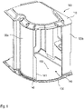
- FIG. 1 illustrates a toilet cabin 100 for a railway vehicle.
- the toilet cabin 100 includes a ceiling assembly 110, at least two sidewalls 120a, 120b extending between the bottom 150 and the ceiling assembly 110, and a curved sliding door 140.
- a door opening 145 is arranged between and defined by opposite side edges of the at least two sidewalls 120.
- At least one of the sidewalls 120a can be at least partially curved to form, together with the curved sliding door 140, a partially curved outer shape of the toilet cabin.
- the toilet cabin 100 may include a substantially flat sidewall 120b, such as shown to the right of the door opening 145, and an at least partially curved sidewall 120a, such as shown to the left of the door opening.
- the sliding door 140 closes the door opening 145 when moving towards the substantially flat sidewall 120b.
- a closing mechanism for the sliding door 140 is attached above the top side of the ceiling assembly 110.
- the door leaf of the sliding door 140 moves behind the partially curved sidewall 120a at the inner side of the curved sidewall 120.
- the toilet cabin 100 may be a self-supporting toilet cabin where the bottom 150, the at least two sidewalls 120a, 120b, and the ceiling assembly 110 form a self-supporting structure.
- the bottom 150 may be formed by the inner floor of the railway vehicle and the at least two sidewalls 120a, 120b are fixed to the floor or to a supporting structure attached to the floor.
- the specific arrangement of the toilet cabin 100 is not limited as the closing mechanism can be used for any type of toilet cabins 100.
- Embodiments of the self-closing door assembly comprising a curved sliding door 140 and a closing mechanism are described with reference to Figures 2A , 2B , 4A and 4C.
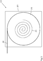
- Figure 3 shows a spring device with a spiral spring which may be used in the embodiment shown in Figures 2A and 2B .
- Figure 5 shows a spring device with a helical spring which may be used in the embodiment shown in Figures 4A and 4B .
- FIGS. 2A and 2B a self-closing door assembly having a spring device 210 with a spiral spring for winding up a connecting element 220 according to an embodiment is described.
- the connecting element 220 is referred to as flexible connecting element as it is preferably flexible and inelastic.
- the sliding door 140 is shown in a closed position in Figure 2A and in an open position in Figure 2B .
- the flexible connecting element 220 connects a leading edge 141 of the door leaf of the sliding door 140 with the spiral spring of the spring device 210.
- the spiral spring 211 see Figure 3 , is accommodated within a housing 213 of the spring device 210.
- the spring device 210 may be a spring rope pulley.
- the spring device 210 may further include a roll 212 that is connected with the spiral spring 211 which is arranged within the roll 212.
- the flexible connecting element 220 is wound up on the outer circumference of the roll 212.
- the flexible connecting element 220 may be a rope which is a simple and cost-efficient, yet a reliable, flexible but inelastic connecting element.
- Another preferred embodiment includes a cable. Further embodiments include a chain or a belt.
- the spiral spring 211 engages with the roll to drive the roll 212 for winding up the flexible connecting element 220.
- the flexible connecting element 220 is unwound by the action of the sliding door 140 moving towards its open position and causes the roll 212 to tension the spiral spring 211.
- the flexible connecting elements 220 is connected to the leading edge 141 of the door leaf
- the flexible connecting element 220 can also be connected with other portions of the door leaf such as at a position spaced by a given distance from the leading edge 141.
- the flexible connecting element 220 engages with a damping element 230 which is arranged between the spring device 210 and the leading edge 141 of the closed sliding door 140.
- the damping element 230 may also divert the flexible connecting element 220 to increase engagement between the flexible connecting element 220 and the damping element 230.
- the damping element 230 may be a radial damper that damps rotation of a roll or wheel which engages with the flexible connecting element 220. If a chain or a belt is used as the flexible connecting element 220, the roll of the damping element 230 may include teeth to improve engagement with the chain. A belt may also be used in combination with a cylindrical roll. Alternatively, the flexible connecting element 220 may be wound around the roll which also increases the engagement.
- auxiliary pulleys can be used to locally divert the flexible connecting element 220 partially around the roll of the damping element 230.
- the flexible connecting element 220 may be locally forced to follow an S-shaped or U-shaped path to increase engagement with the roll or wheel of the damping element 230.
- the damping force of the damping element 230 may be adjustable.
- the damping element 230 may not even decelerate movement of the sliding door 140 but also actively draws the sliding door 140 into its final closed position.
- a plurality of diverter elements 240, 240a are arranged approximately along the curved path of the sliding door 140.
- five diverter elements 240, 240a can be used without being limited thereto.
- at least three, particularly at least four diverter elements 240, 240a are used.
- the diverter elements 240, 240a cooperate with and guides the flexible connecting element 220 so that the flexible connecting element 220 approximately follows the course of the sliding door 140. This results in a mutual action between the sliding door 140 and the flexible connecting element 220 to be always tangential relative to the predefined curved path of the sliding door 140. Forces acting radially on the sliding door 140 are thus avoided which prevents impairing movement of the sliding door 140.
- the sliding door 140 is shown in its closed position in Figure 2A .
- a safety element 270 is provided which damps movement of the sliding door 140 immediately before the sliding door 140 is fully closed.
- the safety element 270 may be an end position damper which may be fastened to that sidewall 120b towards which the sliding door 140 moves when closing.
- the safety element 270 may be a hydraulic element including a piston that displaces oil in a cylinder and thus absorbs the kinetic energy of the moving sliding door 140.
- the safety element 270 may have different damping characteristics such as uniform damping over the whole stroke of the piston or progressive characteristic with initial gentle start and progressive damping as the piston is moving.
- the safety element 270 may include an internal spring which pushes the piston back.
- the hydraulic damping also provides for a controlled and reliably, particularly gently, damping irrespective of the size and weight of the sliding door 140. Furthermore, impact on the movement of the sliding door 140 by vehicle movement can be absorbed by the safety element 270.
- the spring device 210 When the sliding door 140 is moved towards its open position, the spring device 210 becomes increasingly tensioned. It is not required to always open the sliding door 140 to its maximum open position as the spring device 210 will be sufficiently tensioned even when the sliding door 140 is opened to any intermediate position. Preferably, the spring device 210 is already tensioned when the sliding door 140 is in its closed position. The "pre-tension" of the spring device 210 ensures that the sliding door 140 can reliably be closed and is kept closed even when the railway vehicle moves.
- the timer element 250 is preferably a mechanical timer, particularly a mechanical timer with adjustable delay time, preferably without electromechanical components.
- a lever of the timer element 250 may be in engagement with a counterpart attached to the sliding door 140. The lever is movable and is pushed into engagement when the sliding door 140 is opened and thus blocks the counterpart. Releasing the counterpart by the lever being in engagement with the counterpart is hydraulically damped using an oil piston.
- the hydraulic damping can be adjusted, for example by controlling the opening size of a value that limits flow of a hydraulic fluid within a piston that acts on the lever.
- FIG. 4A and 4B another embodiment of the self-closing door assembly is described. Unlike the embodiment of Figures 2A and 2B , the embodiment of Figures 4A and 4B employs a spring device 260 with a helical spring that is expanded, and which contracts, along a straight line.
- Figure 5 illustrates a spring device 260 which may be used in combination with the embodiment of Figures 4A and 4B . The remaining parts may be the same as in the embodiment shown in Figures 2A and 2B .
- the spring device 260 may include an outer tube 261, an inner tube 262, and a helical spring 265 which is wound around the inner tube 262.
- the outer tube 261 and the inner tube 262 define together a space between the inner tube 262 and the outer tube 261 along which the helical spring 265 can be linearly expanded and contracted.
- inner tube 262 and outer tube 261 guides movement of the helical spring 265.
- the outer tube 261 may be provided with fastening means to attach the spring device 260 at the ceiling of the toilet cabin 100.
- a forward end of the helical spring 265 is connected with the flexible connecting element 220.
- a fastener 267 connects the forward end of the helical spring 265 with the flexible connecting element 220.
- the inner tube 262 may be provided with a slit 263 extending along the longitudinal extension of the inner tube 262.
- the fastener 267 extends through the slit 263. When the helical spring 265 contracts, the fastener 267 draws the flexible connecting element 220 into the inner tube 262 so that the flexible connecting element 220 and the helical spring 265 do not accommodate the same space.
- Figure 4A shows the sliding door 140 in its closed position while Figure 4B shows the sliding door 140 in its open position.
- the opening and closing sequence are the same so that a repetition of the detailed explanation is omitted.
- the spring device 210, 260 can be arranged at virtually any position when additional diverter elements are used to divert the flexible connecting element 220 towards the spring device 210, 260.
- a diverter element 240a may be arranged where the leading edge 141 of the sliding door 140 comes to rest when the sliding door 140 is in the closed position.
- no additional diverter element is arranged between the diverter element 240a and the respective spring device 210, 260.
- an additional diverter element may be positioned such that the spring device 210, 260 can be arranged at a location other than that shown in the drawings.
- the self-closing door assembly kit can be used with advantage to retrofit manual curved sliding doors, not only in railway vehicles but also in buildings. Only few components are needed which can be arranged in a flexible manner to take account of the specific design and the available installation space.
Landscapes
- Engineering & Computer Science (AREA)
- Mechanical Engineering (AREA)
- Health & Medical Sciences (AREA)
- Epidemiology (AREA)
- General Health & Medical Sciences (AREA)
- Public Health (AREA)
- Closing And Opening Devices For Wings, And Checks For Wings (AREA)
- Wing Frames And Configurations (AREA)
- Vibration Dampers (AREA)
- Power-Operated Mechanisms For Wings (AREA)
- Residential Or Office Buildings (AREA)
Abstract
Description
- Embodiments of the present invention relate to a self-closing door assembly for a curved sliding door such as a curved sliding door for a toilet cabin of a railway vehicle. Further embodiments pertain to a toilet cabin for railway vehicles having a self-closing door assembly for the curved sliding door of the toilet cabin. Further embodiments of the present invention pertain to a self-closing door assembly kit for retrofitting manual sliding doors particularly curved sliding doors moving along a predefined curved path between an open position and a closed position.
- Railway vehicles for public mass transport are equipped with facilities such as toilets to improve passengers' comfort. The space in a railway vehicle is often limited so that the facilities are configured so as to use the available space most efficiently. For that reason, toilet compartments are designed to have, at least partially, walls with a curved or arc-shaped (shape of circular segment) outer contour. To take most advantage of this outer contour of the walls, the door leaf of a curved sliding door used to close the toilet compartment has also a curved or arc-shape so that the door can be moved along a circular path following the curved contour of the toilet compartment.
- Modern railway vehicles are often equipped with fully automatic doors which can be operated by pressing a button by which an opening and closing mechanism is actuated. While those automatic doors are very convenient, they require extra equipment such as an electrical motor or other suitable electromechanical components which not only contribute to the total weight of the railway vehicle but may be prone to failure and require additional maintenance.
- Sliding doors with different closing mechanisms are known. For example,
CN 112027869 A andCN 210558803 U describe a self-closing structure of an elevator landing door.KR 102001453 B1 CN 109693992 A describes an electromagnetic type landing door self-closing system.CN 108974027 A discloses a double linkage sliding door device for a toilet compartment of a railway vehicle.CN 206049681 U describes another self-closing mechanism for railway vehicles.EP 3259166 B1 describes a cabin with a rotatable cabin door for a vehicle.CN 204237414 U describes a self-closing door assembly for an elevator.KR 101407381 B1 CN 102296901 B discloses a device for automatically opening and closing a cabin door.EP 1409824 A1 discloses a closing sequence control device for a self-closing door.DE 3934269 A1 discloses a self-closing device for a door or window. - However, these mechanisms are often complicated and not suited for the limited space available in a railway vehicle.
- In view of the above, there is need for improvement.
- The above problem is solved by a self-closing door assembly for a sliding door according to claim 1, a toilet cabin for a railway vehicle according to claim 12, and a self-closing door assembly kit according to claim 15. Further embodiments, modifications, aspects and advantages are disclosed in the dependent claims and the following description.
- According to an embodiment, which can be combined with any other embodiment described herein, a self-closing door assembly of a curved sliding door includes a curved sliding door movable along a predefined curved path between an open position and a closed position, and a closing mechanism. The closing mechanism includes a spring device to move the sliding door into the closed position; a connecting element having a first end connected to the spring device and a second end connected to the sliding door; a plurality of diverter elements arranged along the curved path of the sliding door for guiding the connecting element along the curved path; and a damping element in engagement with the connecting element to limit movement of the connecting element when the connecting element is pulled by the spring device for moving the sliding door into the closed position. The spring device is tensioned, through transmission by the connecting element, when the sliding door towards the open position.
- The self-closing door assembly is composed of few reliable mechanical elements and allows retrofitting of existing manual curved sliding doors. A challenge for curved sliding doors moving along a predefined curved path is that the door leaf of the sliding door rotates about a vertical axis which is off-set to the door leaf. Thus, a simple push-pull mechanism would not be a suitable choice for curved sliding doors. The present invention overcomes these drawbacks by using a connecting element which connects the spring device with the sliding door. The diverter elements are arranged along the moving path of the curved sliding door and guide the connecting element so that the connecting element can follow the predefined curved path along which the sliding door moves. The connecting element can therefore always pull the sliding door tangentially along the predefined curved path maximising the force transmitted from the spring device on the sliding door when closing the sliding door.
- As a connecting element and diverter elements are used, the directional operation of the spring device does not need to be aligned with any tangential direction of the predefined curved path. This provides more freedom for arranging the spring device. The connecting element is typically bendable so that, when it moves together with the door leaf, it is bent to follow the curved path.
- The diverter elements of the plurality of diverter elements can be arranged separately along the curved path. Along the curved path, a diverter element of the plurality of diverter elements can be arranged distant to another diverter element of the plurality of diverter elements, in particular distant to each other diverter element of the plurality of diverter elements. According to an embodiment, all diverter elements are arranged spaced from each other. In an embodiment, along the path, a gap is arranged between a diverter element and another diverter element, particularly a consecutive diverter element of the plurality of diverter elements. A length of the gap along the direction of the curved path can be larger than an extension of a diverter element along the curved path. Particularly, the length of the gap can be larger than a diameter of the diverter element of the plurality of diverter elements. Along the curved path, the plurality of diverter elements can be arranged equally distributed.
- When referring to a curved path and a curved sliding door, basically any shape of a curve is meant. The curved path and the curved sliding door are specifically arc-shaped (circularly arc-shaped), i.e. they correspond to a segment of a circle. In typical embodiments, the segment is not more than a 90-degree circular arc.
- The driving element for closing the sliding door is provided by the spring device which is tensioned when the sliding door is manually opened by user. As the sliding door advances into its open position by action of the user, the connecting element pulls on the spring device and tensions a spring arranged within the spring device. If the user does not actively keep the sliding door open or block the sliding door, or if the door is not blocked by other means, the energy stored in the spring device results in a retracting force pulling the sliding door back into its closed position. Thus, the spring device acts as a mechanical energy storage means which stores tension energy supplied to the spring device, particularly to a spring of the spring device, when the sliding door is manually opened. The stored tension energy is used to close the sliding door.
- The damping element limits the movement of the door, particularly the maximum speed at which the sliding doors closes. This is for the users' comfort and safety. The damping element can limit the movement of the door with respect to the speed at which the sliding door can move, particularly the speed at which the sliding door opens and/or closes.
- The damping element can be arranged and configured to restrict the speed at which the sliding door closes. The damping element can decelerate the closing of the sliding door. The damping element can be arranged and configured for a smooth closing of the sliding door. The damping element can be arranged and configured to limit the speed of the sliding door during the movement of the door from its open position to its closed position.
- The damping element can limit the maximum speed at which the sliding doors opens. Preferably, a damping element with asymmetric action is used. For example, the damping element may damp the closing movement of the sliding door more than the opening movement to allow the user to open the door more quickly. The maximum speed at which the sliding door can be opened may also be limited for safety reasons. The damping element can be arranged and configured to restrict the speed at which the sliding door opens. The damping element can decelerate the opening of the sliding door. The damping element can be arranged and configured for a smooth opening of the sliding door. The damping element can be arranged and configured to limit the speed of the sliding door during the movement of the door from its closed position to its open position. According to an embodiment, the damping element can be arranged and configured to restrict the speed at which the sliding door opens less than the speed at which the sliding door closes.
- The self-closing door assembly described herein is particularly suitable for manually operated doors, i.e. for non-automatic doors which are not driven, or not partly driven, by electromechanical drive units. Moreover, the self-closing door assembly is easy to install, allows great flexibility for adapting to local geometries and designs, and is a cost-efficient solution. Specifically, for opening of the sliding door, manual operation, i.e. manual moving of the door by a user or passenger, is needed. The closing of the sliding door occurs automatically in the sense that the spring device brings the sliding door back into its closed position. The sliding door can also be closed manually. The self-closing door assembly is therefore autonomous as it does not require supply of electrical energy. It is semi-automatic (as it closes the sliding door automatically but requires manual work to open it) and fully mechanical as the closing can occur by action of the closing mechanism without requiring any electromechanical component and supply of electrical energy.
- In addition to that, the self-closing door assembly described herein is particularly of advantage for curved sliding doors such as arc-shaped doors as diverter elements are used to guide the connecting element virtually along any curved path.
- The spring device may include a housing for accommodating a spring arranged within the housing. The housing may include fastening means for attaching the spring device to structural elements such as a ceiling or a wall.
- According to an embodiment, which can be combined with any other embodiment described herein, the spring device includes a spiral spring (torsion spring) for winding up the connecting element, which may be bendable or flexible but inelastic. For example, the spring device may be a spring rope pulley. A spiral spring allows for a compact design of the spring device. Furthermore, the spring force can be easily adjusted by the number of windings of the spiral spring. For example, if the spiral spring is provided with a higher number of windings and is pretensioned, the spring force can be kept in a linear range of the spring regardless of whether the door is fully opened or closed. In fact, when using a higher number of windings, the spring force can be kept approximately constant over the operating range defined by the maximum opening range of the sliding door.
- According to an embodiment, which can be combined with any other embodiment described herein, the spring device includes an outer tube accommodating a helical spring (helical tension spring - linear tension spring) which is expanded along a longitudinal extension of the outer tube when moving the sliding door towards the open position. Instead of a spiral spring that winds up the connecting element, a helical spring can be used which linearly expands when the sliding door is opened. The spring device may have an elongated shape such as a shape of a tube. Specifically, an outer tube can accommodate the helical spring so that the helical spring is protected and guided at its outer side. The helical spring expands within and along the longitudinal extension of the outer tube. The outer tube may be provided with the fastening means for attaching the spring device to structural elements such as the ceiling of a cabin.
- According to an embodiment, which can be combined with any other embodiment described herein, the spring device further includes an inner guiding element arranged in and extending along the outer tube, wherein the helical spring is wound around the inner guiding element and between the inner guiding element and the outer tube. Inner and outer tube cooperate together for guiding the helical spring and to prevent the helical spring from disengaging or deforming when expanding or contracting. The inner and outer tubes may be arranged coaxially relative to each other.
- According to an embodiment, which can be combined with any other embodiment described herein, the inner guiding element includes an inner tube for guiding the connecting member therein. The inner tube may have a longitudinal slit through which a forward end of the helical spring connected with the connecting element extends into an interior of the inner tube. The connecting element is drawn into the inner tube when the helical spring contracts. The connection between the forward end of the helical spring and the connecting element is established through the longitudinal slit. For example, a fastener may be provided at the forward end of the helical spring which establishes the connection with the connecting element. The fastener may be guided along the slit to facilitate linear movement of the forward end of the helical spring and the connecting element.
- According to an embodiment, which can be combined with any other embodiment described herein, the connecting element is flexible and inelastic. For example, the connecting element may be an inelastic rope, a chain, a cable, or a belt. The connecting element is preferably not elastic so that the connecting element can immediately transmit the force exerted from the spring device, i.e. from the spring of the spring device, to the sliding door or, when the sliding door is manually opened, from the sliding door to the spring device. The connecting element is thus, unlike the spring device, not an energy storage means. The connecting element can also be described as being limp. The flexibility the connecting element is provided with allows the connecting element to follow the curved path defined by the diverter elements without requiring application of a force, or only of a marginal force, for bending the connecting element.
- According to an embodiment, which can be combined with any other embodiment described herein, the damping element is a radial damper, particularly a radial damper with adjustable predefined damping force. The predefined damping force may define the maximum speed for the closing movement of the sliding door. The predefined damping force is adjustable to allow adaptation to different scenarios and door constructions. Furthermore, the damping force may need to be adjusted after some time of operation, such as at regular maintenance intervals.
- According to an embodiment, which can be combined with any other embodiment described herein, the closing mechanism further includes a timer element adapted to keep the sliding door in the open position for a predetermined delay time and to release the sliding door after lapse of the predetermined delay time. Keeping the sliding door in its open position for a predetermined time provides more comfort for the user as he passes the door. There is no need for the user to manually keep the door open. This is of particular importance for elderly people or differently abled persons, for example a person needing a wheelchair.
- According to an embodiment, which can be combined with any other embodiment described herein, the timer element is a mechanical timer, particularly a mechanical timer with adjustable delay time, preferably without electromechanical components.
- According to an embodiment, which can be combined with any other embodiment described herein, the closing mechanism further comprises a safety element for stopping the sliding door from reaching the closed position. The safety element is particularly an end position stopper decelerating movement of the door. The safety element prevents trapping of fingers or other body parts by the closing door.
- According to an embodiment, which can be combined with any other embodiment described herein, a toilet cabin for a railway vehicle is provided. The toilet cabin includes a bottom, a ceiling assembly, at least two sidewalls extending between the bottom and the ceiling assembly, and a self-closing door assembly according to any of the embodiments described herein. The spring device, the plurality of diverter elements and the damping element of the self-closing door assembly are attached to the ceiling assembly. The connecting element is attached to an upper end of the sliding door. The self-closing door assembly as described herein is particularly useful for toilet cabins of railway vehicles. However, the invention is not limited thereto and can also be applied to other cabins having a manually operated curved sliding door, for example for any cabin in a railway vehicle, in any other vehicle such as vessels, or in buildings.
- According to an embodiment, which can be combined with any other embodiment described herein, the spring device, the plurality of diverter elements and the damping element of the self-closing door assembly are arranged in a common level plane extending parallel to the bottom of the cabin. Preferably, all elements of the self-closing assembly are attached or fastened on the ceiling of the cabin. The working operation of all moving and movable parts of the self-closing assembly are preferably within a common level plane.
- According to an embodiment, which can be combined with any other embodiment described herein, the toilet cabin further includes a bottom guiding rail in engagement with a lower end of the sliding door to guide the sliding door at its lower end. This bottom guiding rail stabilizes the door leaf of the sliding door at its lower end. Alternatively or in addition to the bottom guiding rail, a top guiding rail may also be provided which is in engagement with an upper end of the sliding door.
- According to an embodiment, which can be combined with any other embodiment described herein, a self-closing door assembly kit for a curved sliding door, which is movable along a predefined curved path between an open position and a closed position, is provided. The kit includes a spring device; a connecting element having a first end for connecting to the spring device and a second end for connecting to the sliding door; a plurality of diverter elements for arranging along the curved path of the sliding door for guiding the connecting element; and a damping element for engagement with the connecting element to limit movement of the connecting element. The self-closing door assembly kit can further optionally include a timer element adapted to keep the sliding door in the open position for a predetermined delay time and to release the sliding door after the elapsing of the predetermined delay time; and a safety element for stopping movement of the sliding door.
- The assembly kit may be used to retrofit an existing manual sliding door, for example in railway vehicles.
- The invention will now be described with reference to embodiments without limiting the scope as defined by the claims.
- The appended drawings illustrate embodiments and serve in combination with the description for explaining the principles of the invention. Elements in the drawings are relative to each other and are not necessarily to scale unless otherwise stated.
-
Figure 1 illustrates a toilet cabin for a railway vehicle according to an embodiment. -
Figures 2A and2B illustrates, from above, a top view onto a ceiling of a toilet cabin equipped with a self-closing door assembly according to an embodiment, whereinFigure 2A illustrates the operation of the self-closing door assembly when the sliding door is in its closed position andFigure 2B illustrates the operation of the self-closing door assembly when the sliding door is in its open position. -
Figure 3 illustrates an example of a spring device having a spiral spring. -
Figures 4A and4B illustrates, from above, a top view onto a ceiling of a toilet cabin equipped with a self-closing door assembly according to another embodiment, whereinFigure 4A illustrates the operation of the self-closing door assembly when the sliding door is in its closed position andFigure 4B illustrates the operation of the self-closing door assembly when the sliding door is in its open position. -
Figure 5 illustrates a partial view of a spring device having an inner tube, and outer tube and a helical spring. -
Figure 1 illustrates atoilet cabin 100 for a railway vehicle. Thetoilet cabin 100 includes aceiling assembly 110, at least two sidewalls 120a, 120b extending between the bottom 150 and theceiling assembly 110, and a curved slidingdoor 140. Adoor opening 145 is arranged between and defined by opposite side edges of the at least two sidewalls 120. At least one of the sidewalls 120a can be at least partially curved to form, together with the curved slidingdoor 140, a partially curved outer shape of the toilet cabin. Thetoilet cabin 100 may include a substantiallyflat sidewall 120b, such as shown to the right of thedoor opening 145, and an at least partiallycurved sidewall 120a, such as shown to the left of the door opening. The slidingdoor 140 closes thedoor opening 145 when moving towards the substantiallyflat sidewall 120b. A closing mechanism for the slidingdoor 140 is attached above the top side of theceiling assembly 110. - When opening the sliding
door 140, the door leaf of the slidingdoor 140 moves behind the partiallycurved sidewall 120a at the inner side of the curved sidewall 120. - The
toilet cabin 100 may be a self-supporting toilet cabin where the bottom 150, the at least two sidewalls 120a, 120b, and theceiling assembly 110 form a self-supporting structure. Alternatively, the bottom 150 may be formed by the inner floor of the railway vehicle and the at least two sidewalls 120a, 120b are fixed to the floor or to a supporting structure attached to the floor. - The specific arrangement of the
toilet cabin 100 is not limited as the closing mechanism can be used for any type oftoilet cabins 100. - Embodiments of the self-closing door assembly comprising a curved sliding
door 140 and a closing mechanism are described with reference toFigures 2A ,2B ,4A and 4C.Figure 3 shows a spring device with a spiral spring which may be used in the embodiment shown inFigures 2A and2B .Figure 5 shows a spring device with a helical spring which may be used in the embodiment shown inFigures 4A and4B . - Turning first to
Figures 2A and2B , a self-closing door assembly having aspring device 210 with a spiral spring for winding up a connectingelement 220 according to an embodiment is described. In the following, the connectingelement 220 is referred to as flexible connecting element as it is preferably flexible and inelastic. The slidingdoor 140 is shown in a closed position inFigure 2A and in an open position inFigure 2B . - The flexible connecting
element 220 connects aleading edge 141 of the door leaf of the slidingdoor 140 with the spiral spring of thespring device 210. Thespiral spring 211, seeFigure 3 , is accommodated within ahousing 213 of thespring device 210. Thespring device 210 may be a spring rope pulley. Thespring device 210 may further include aroll 212 that is connected with thespiral spring 211 which is arranged within theroll 212. The flexible connectingelement 220 is wound up on the outer circumference of theroll 212. The flexible connectingelement 220 may be a rope which is a simple and cost-efficient, yet a reliable, flexible but inelastic connecting element. Another preferred embodiment includes a cable. Further embodiments include a chain or a belt. Thespiral spring 211 engages with the roll to drive theroll 212 for winding up the flexible connectingelement 220. On the other hand, when the slidingdoor 140 is manually opened by a passenger the flexible connectingelement 220 is unwound by the action of the slidingdoor 140 moving towards its open position and causes theroll 212 to tension thespiral spring 211. - While the present embodiments show that the flexible connecting
elements 220 is connected to theleading edge 141 of the door leaf, the flexible connectingelement 220 can also be connected with other portions of the door leaf such as at a position spaced by a given distance from theleading edge 141. - Turning back to
Figures 2A and2B , the flexible connectingelement 220 engages with a dampingelement 230 which is arranged between thespring device 210 and theleading edge 141 of the closed slidingdoor 140. The dampingelement 230 may also divert the flexible connectingelement 220 to increase engagement between the flexible connectingelement 220 and the dampingelement 230. - The damping
element 230 may be a radial damper that damps rotation of a roll or wheel which engages with the flexible connectingelement 220. If a chain or a belt is used as the flexible connectingelement 220, the roll of the dampingelement 230 may include teeth to improve engagement with the chain. A belt may also be used in combination with a cylindrical roll. Alternatively, the flexible connectingelement 220 may be wound around the roll which also increases the engagement. - If the damping
element 230 does not divert the flexible connectingelement 220, additional auxiliary pulleys can be used to locally divert the flexible connectingelement 220 partially around the roll of the dampingelement 230. For example, by means of cooperation of one or two auxiliary pulleys with the roll of the dampingelement 230, the flexible connectingelement 220 may be locally forced to follow an S-shaped or U-shaped path to increase engagement with the roll or wheel of the dampingelement 230. - The damping force of the damping
element 230 may be adjustable. - According to an embodiment, the damping
element 230 may not even decelerate movement of the slidingdoor 140 but also actively draws the slidingdoor 140 into its final closed position. - As illustrated in
Figures 2A and2B , a plurality ofdiverter elements door 140. For example, fivediverter elements diverter elements - The
diverter elements element 220 so that the flexible connectingelement 220 approximately follows the course of the slidingdoor 140. This results in a mutual action between the slidingdoor 140 and the flexible connectingelement 220 to be always tangential relative to the predefined curved path of the slidingdoor 140. Forces acting radially on the slidingdoor 140 are thus avoided which prevents impairing movement of the slidingdoor 140. - The sliding
door 140 is shown in its closed position inFigure 2A . To prevent the passenger's finger becoming trapped when the slidingdoor 140 closes, asafety element 270 is provided which damps movement of the slidingdoor 140 immediately before the slidingdoor 140 is fully closed. Thesafety element 270 may be an end position damper which may be fastened to thatsidewall 120b towards which the slidingdoor 140 moves when closing. For example, thesafety element 270 may be a hydraulic element including a piston that displaces oil in a cylinder and thus absorbs the kinetic energy of the moving slidingdoor 140. Thesafety element 270 may have different damping characteristics such as uniform damping over the whole stroke of the piston or progressive characteristic with initial gentle start and progressive damping as the piston is moving. To return the piston into its initial position when the slidingdoor 140 is opened, thesafety element 270 may include an internal spring which pushes the piston back. The hydraulic damping also provides for a controlled and reliably, particularly gently, damping irrespective of the size and weight of the slidingdoor 140. Furthermore, impact on the movement of the slidingdoor 140 by vehicle movement can be absorbed by thesafety element 270. - Turing to
Figure 2B the slidingdoor 140 is shown in its open position with the flexible connectingelement 220 pulled out from thespring device 210 to is maximum extension. As shown inFigure 2B , the flexible connectingelement 220 follows the predefined curved path of the slidingdoor 140 because of thediverter elements - When the sliding
door 140 is moved towards its open position, thespring device 210 becomes increasingly tensioned. It is not required to always open the slidingdoor 140 to its maximum open position as thespring device 210 will be sufficiently tensioned even when the slidingdoor 140 is opened to any intermediate position. Preferably, thespring device 210 is already tensioned when the slidingdoor 140 is in its closed position. The "pre-tension" of thespring device 210 ensures that the slidingdoor 140 can reliably be closed and is kept closed even when the railway vehicle moves. - When the passenger opens the sliding
door 140, it comes in engagement with atimer element 250 which keeps the slidingdoor 140 open for a predetermined delay time. The predetermined delay time can be adjusted and may be about few seconds. After lapse of the predetermined delay time thetimer element 250 releases the slidingdoor 140 which then closes by action of thespring device 210. Thetimer element 250 is preferably a mechanical timer, particularly a mechanical timer with adjustable delay time, preferably without electromechanical components. For example, a lever of thetimer element 250 may be in engagement with a counterpart attached to the slidingdoor 140. The lever is movable and is pushed into engagement when the slidingdoor 140 is opened and thus blocks the counterpart. Releasing the counterpart by the lever being in engagement with the counterpart is hydraulically damped using an oil piston. The hydraulic damping can be adjusted, for example by controlling the opening size of a value that limits flow of a hydraulic fluid within a piston that acts on the lever. - With reference to
Figures 4A and4B another embodiment of the self-closing door assembly is described. Unlike the embodiment ofFigures 2A and2B , the embodiment ofFigures 4A and4B employs aspring device 260 with a helical spring that is expanded, and which contracts, along a straight line.Figure 5 illustrates aspring device 260 which may be used in combination with the embodiment ofFigures 4A and4B . The remaining parts may be the same as in the embodiment shown inFigures 2A and2B . - The
spring device 260 may include anouter tube 261, aninner tube 262, and ahelical spring 265 which is wound around theinner tube 262. Theouter tube 261 and theinner tube 262 define together a space between theinner tube 262 and theouter tube 261 along which thehelical spring 265 can be linearly expanded and contracted. Thus,inner tube 262 andouter tube 261 guides movement of thehelical spring 265. - The
outer tube 261 may be provided with fastening means to attach thespring device 260 at the ceiling of thetoilet cabin 100. - A forward end of the
helical spring 265 is connected with the flexible connectingelement 220. For example, afastener 267 connects the forward end of thehelical spring 265 with the flexible connectingelement 220. - For guiding the flexible connecting
element 220 within thespring device 260, theinner tube 262 may be provided with aslit 263 extending along the longitudinal extension of theinner tube 262. Thefastener 267 extends through theslit 263. When thehelical spring 265 contracts, thefastener 267 draws the flexible connectingelement 220 into theinner tube 262 so that the flexible connectingelement 220 and thehelical spring 265 do not accommodate the same space. - Similar to
Figures 2A and2B ,Figure 4A shows the slidingdoor 140 in its closed position whileFigure 4B shows the slidingdoor 140 in its open position. The opening and closing sequence are the same so that a repetition of the detailed explanation is omitted. - In all embodiments shown herein, the
spring device element 220 towards thespring device diverter element 240a may be arranged where theleading edge 141 of the slidingdoor 140 comes to rest when the slidingdoor 140 is in the closed position. In the embodiments shown inFigures 2A ,2B ,4A and4B , no additional diverter element is arranged between thediverter element 240a and therespective spring device spring device - The self-closing door assembly kit can be used with advantage to retrofit manual curved sliding doors, not only in railway vehicles but also in buildings. Only few components are needed which can be arranged in a flexible manner to take account of the specific design and the available installation space.
- Although specific embodiments are illustrated and described herein, the skilled person will appreciate that the embodiments can be modified without departing from the scope of the invention as defined by the claims.
-
- 100
- toilet cabin
- 110
- ceiling assembly
- 120a, 120b
- side wall
- 130
- bottom guiding rail
- 140
- door
- 141
- leading edge
- 145
- door opening
- 150
- bottom
- 210
- spring device
- 211
- spiral spring
- 212
- roll
- 213
- housing of spring device
- 220
- connecting element / rope
- 230
- damping element
- 240, 240a
- diverter element
- 250
- timer element
- 260
- spring device
- 261
- outer tube
- 262
- inner tube
- 263
- slit
- 265
- helical spring / helical tension spring
- 267
- fastener
- 270
- safety element
Claims (15)
- Self-closing door assembly of a curved sliding door, comprising:a curved sliding door movable along a predefined curved path between an open position and a closed position; anda closing mechanism comprising:a spring device to move the sliding door into the closed position;a connecting element having a first end connected to the spring device and a second end connected to the sliding door, the spring device being tensioned when moving the sliding door towards the open position;a plurality of diverter elements arranged along the curved path of the sliding door for guiding the connecting element along the curved path; anda damping element in engagement with the connecting element to limit movement of the connecting element when the connecting element is pulled by the spring device for moving the sliding door into the closed position.
- Self-closing door assembly according to claim 1, wherein the spring device comprises a spiral spring for winding up the connecting element.
- Self-closing door assembly according to claim 1 or 2, wherein the spring device comprises a spring rope pulley.
- Self-closing door assembly according to claim 1, wherein the spring device comprises an outer tube accommodating a helical spring which is expanded along a longitudinal extension of the outer tube when moving the sliding door towards the open position.
- Self-closing door assembly according to claim 4, wherein the spring device further comprises an inner guiding element arranged in and extending along the outer tube, wherein the helical spring is wound around the inner guiding element and between the inner guiding element and the outer tube.
- Self-closing door assembly according to claim 5, wherein the inner guiding element comprises an inner tube for guiding the connecting element therein, wherein the inner tube has a longitudinal slit through which a forward end of the helical spring connected with the connecting element extends into an interior of the inner tube.
- Self-closing door assembly according to any of the previous claims, wherein the connecting element is flexible but inelastic and comprises one of an inelastic rope, a cable, a chain, or a belt.
- Self-closing door assembly according to any of the previous claims, wherein the damping element is a radial damper, particularly a radial damper with adjustable predefined damping force.
- Self-closing door assembly according to any of the previous claims, wherein the closing mechanism further comprises a timer element adapted to keep the sliding door in the open position for a predetermined delay time and to release the sliding door after elapsing of the predetermined delay time.
- Self-closing door assembly according to the previous claim, wherein the timer element is a mechanical timer, particularly a mechanical timer with adjustable delay time, preferably without electromechanical components.
- Self-closing door assembly according to the previous claim, wherein the closing mechanism further comprises a safety element for stopping the sliding door prior to reaching the closed position, wherein the safety element is particularly an end position stopper decelerating movement of the sliding door.
- Toilet cabin for a railway vehicle, comprising a bottom, a ceiling assembly, at least two sidewalls extending between the bottom and the ceiling assembly, and a self-closing door assembly according to any of the previous claims, wherein the spring device, the plurality of diverter elements and the damping element of the self-closing door assembly are attached to the ceiling assembly, wherein the connecting element is attached to an upper end of the sliding door.
- Toilet cabin of claim 12, wherein the spring device, the plurality of diverter elements and the damping element of the self-closing door assembly are arranged in a common level plane extending parallel to the bottom.
- Toilet cabin of claim 12 or 13, further comprising a bottom guiding rail in engagement with a lower end of the sliding door to guide the sliding door at its lower end.
- Self-closing door assembly kit for a curved sliding door, preferably for a self-closing door assembly according to any of claims 1 to 11, which is movable along a predefined curved path between an open position and a closed position, the self-closing door assembly kit comprising:a spring device;a connecting element having a first end for connecting to the spring device and a second end for connecting to the sliding door;a plurality of diverter elements for arranging along the curved path of the sliding door for guiding the connecting element; anda damping element for engagement with the connecting element to limit movement of the connecting element;further optionally comprising:a timer element adapted to keep the sliding door in the open position for a predetermined delay time and to release the sliding door after elapsing of the predetermined delay time; anda safety element for stopping movement of the sliding door.
Applications Claiming Priority (1)
| Application Number | Priority Date | Filing Date | Title |
|---|---|---|---|
| GB2109965.0A GB2608653B (en) | 2021-07-09 | 2021-07-09 | Self-closing door assembly of a sliding door, toilet cabin for a railway vehicle, and self-closing door assembly kit |
Publications (2)
| Publication Number | Publication Date |
|---|---|
| EP4116168A1 true EP4116168A1 (en) | 2023-01-11 |
| EP4116168B1 EP4116168B1 (en) | 2025-01-01 |
Family
ID=77353887
Family Applications (1)
| Application Number | Title | Priority Date | Filing Date |
|---|---|---|---|
| EP22182856.9A Active EP4116168B1 (en) | 2021-07-09 | 2022-07-04 | Self-closing door assembly of a sliding door, toilet cabin for a railway vehicle, and self-closing door assembly kit |
Country Status (5)
| Country | Link |
|---|---|
| EP (1) | EP4116168B1 (en) |
| CN (1) | CN115596309A (en) |
| ES (1) | ES3017253T3 (en) |
| GB (1) | GB2608653B (en) |
| PL (1) | PL4116168T3 (en) |
Families Citing this family (1)
| Publication number | Priority date | Publication date | Assignee | Title |
|---|---|---|---|---|
| TWI833652B (en) * | 2023-05-18 | 2024-02-21 | 緯創資通股份有限公司 | Storage device |
Citations (15)
| Publication number | Priority date | Publication date | Assignee | Title |
|---|---|---|---|---|
| DE3934269A1 (en) | 1989-10-13 | 1991-04-18 | Profunda B V | Self-closing device for door or window - has mechanism which holds door stationary in fully open position |
| JPH07293104A (en) * | 1994-04-25 | 1995-11-07 | Showa Spring Kk | Semi-automatic sliding door and its semi-automatic opening / closing device |
| JPH1171924A (en) * | 1997-08-28 | 1999-03-16 | Okamura Corp | Toilet door equipment |
| EP1409824A1 (en) | 2001-02-14 | 2004-04-21 | DORMA GmbH + Co. KG | Closing sequence control device |
| JP2011089353A (en) * | 2009-10-26 | 2011-05-06 | Okamura Corp | Suspension type door device |
| CN102296901A (en) | 2011-08-22 | 2011-12-28 | 南京航空航天大学 | Device capable of automatically opening and closing cabin door in compact cabin body |
| KR101407381B1 (en) | 2012-11-07 | 2014-06-17 | 황창욱 | Sliding door automatic closer |
| CN204237414U (en) | 2014-11-12 | 2015-04-01 | 展鹏科技股份有限公司 | Elevator door self-closing device |
| CN206049681U (en) | 2016-09-28 | 2017-03-29 | 辽宁铁道职业技术学院 | A kind of railway transport vehicle is with being automatically switched off handrail door |
| CN108974027A (en) | 2018-08-06 | 2018-12-11 | 青岛欧特美交通装备有限公司 | A kind of biparting linkage sliding door apparatus of passenger train use in toilet |
| CN109693992A (en) | 2018-11-29 | 2019-04-30 | 日立电梯(中国)有限公司 | A kind of electromagnetic type layer door self-closing system and its control method |
| KR102001453B1 (en) | 2018-11-16 | 2019-07-18 | 김우흥 | Door assembly for handicapped person toilet of train |
| CN210558803U (en) | 2019-07-18 | 2020-05-19 | 上海贝思特门机有限公司 | Forced self-closing structure of elevator landing door |
| EP3259166B1 (en) | 2015-04-30 | 2020-08-26 | Siemens Mobility GmbH | Cabin with rotatable cabin door for a vehicle |
| CN112027869A (en) | 2020-09-03 | 2020-12-04 | 广州广日电梯工业有限公司 | Weight type elevator landing door self-closing device and method thereof |
Family Cites Families (4)
| Publication number | Priority date | Publication date | Assignee | Title |
|---|---|---|---|---|
| CN1676847A (en) * | 2004-03-30 | 2005-10-05 | 三和卷帘门工业株式会社 | Self-closing sliding-door device |
| JP2007126832A (en) * | 2005-11-01 | 2007-05-24 | Asahi Sangyo Kk | Self-closing type sliding door closer |
| JP4879004B2 (en) * | 2006-12-07 | 2012-02-15 | 旭産業株式会社 | Sliding door closer |
| JP4755208B2 (en) * | 2008-01-21 | 2011-08-24 | 株式会社ベスト | Self-closing sliding door device |
-
2021
- 2021-07-09 GB GB2109965.0A patent/GB2608653B/en not_active Expired - Fee Related
-
2022
- 2022-07-04 PL PL22182856.9T patent/PL4116168T3/en unknown
- 2022-07-04 ES ES22182856T patent/ES3017253T3/en active Active
- 2022-07-04 EP EP22182856.9A patent/EP4116168B1/en active Active
- 2022-07-08 CN CN202210805863.0A patent/CN115596309A/en active Pending
Patent Citations (15)
| Publication number | Priority date | Publication date | Assignee | Title |
|---|---|---|---|---|
| DE3934269A1 (en) | 1989-10-13 | 1991-04-18 | Profunda B V | Self-closing device for door or window - has mechanism which holds door stationary in fully open position |
| JPH07293104A (en) * | 1994-04-25 | 1995-11-07 | Showa Spring Kk | Semi-automatic sliding door and its semi-automatic opening / closing device |
| JPH1171924A (en) * | 1997-08-28 | 1999-03-16 | Okamura Corp | Toilet door equipment |
| EP1409824A1 (en) | 2001-02-14 | 2004-04-21 | DORMA GmbH + Co. KG | Closing sequence control device |
| JP2011089353A (en) * | 2009-10-26 | 2011-05-06 | Okamura Corp | Suspension type door device |
| CN102296901A (en) | 2011-08-22 | 2011-12-28 | 南京航空航天大学 | Device capable of automatically opening and closing cabin door in compact cabin body |
| KR101407381B1 (en) | 2012-11-07 | 2014-06-17 | 황창욱 | Sliding door automatic closer |
| CN204237414U (en) | 2014-11-12 | 2015-04-01 | 展鹏科技股份有限公司 | Elevator door self-closing device |
| EP3259166B1 (en) | 2015-04-30 | 2020-08-26 | Siemens Mobility GmbH | Cabin with rotatable cabin door for a vehicle |
| CN206049681U (en) | 2016-09-28 | 2017-03-29 | 辽宁铁道职业技术学院 | A kind of railway transport vehicle is with being automatically switched off handrail door |
| CN108974027A (en) | 2018-08-06 | 2018-12-11 | 青岛欧特美交通装备有限公司 | A kind of biparting linkage sliding door apparatus of passenger train use in toilet |
| KR102001453B1 (en) | 2018-11-16 | 2019-07-18 | 김우흥 | Door assembly for handicapped person toilet of train |
| CN109693992A (en) | 2018-11-29 | 2019-04-30 | 日立电梯(中国)有限公司 | A kind of electromagnetic type layer door self-closing system and its control method |
| CN210558803U (en) | 2019-07-18 | 2020-05-19 | 上海贝思特门机有限公司 | Forced self-closing structure of elevator landing door |
| CN112027869A (en) | 2020-09-03 | 2020-12-04 | 广州广日电梯工业有限公司 | Weight type elevator landing door self-closing device and method thereof |
Also Published As
| Publication number | Publication date |
|---|---|
| GB202109965D0 (en) | 2021-08-25 |
| GB2608653A (en) | 2023-01-11 |
| PL4116168T3 (en) | 2025-04-28 |
| EP4116168B1 (en) | 2025-01-01 |
| GB2608653B (en) | 2024-11-13 |
| ES3017253T3 (en) | 2025-05-12 |
| CN115596309A (en) | 2023-01-13 |
Similar Documents
| Publication | Publication Date | Title |
|---|---|---|
| CN102933118B (en) | Retracting device for retracting a movably supported furniture part | |
| US6588480B2 (en) | Counter wrap cord drive | |
| JP4560442B2 (en) | Sunshade switchgear | |
| EP4116168B1 (en) | Self-closing door assembly of a sliding door, toilet cabin for a railway vehicle, and self-closing door assembly kit | |
| GB2336875A (en) | Motor vehicle : sliding door drive | |
| US6442897B1 (en) | Counterbalance system cable drum for sectional doors | |
| SK125399A3 (en) | Emergency evacuation device | |
| US5377785A (en) | Door closing system | |
| US6918211B2 (en) | Door closing device | |
| EP3095351A1 (en) | Shock-absorbing self-closing device for moving parts of furniture | |
| US20080256873A1 (en) | Automatic sliding door closing device | |
| EP2546447B1 (en) | A motor vehicle with a sliding door and an actuation mechanism for the sliding door | |
| JP7101983B2 (en) | Sliding door closer | |
| JP2672791B2 (en) | Sliding door closing device | |
| JP6043122B2 (en) | Opening / closing member stop device for opening / closing device | |
| KR20110044351A (en) | Sliding retarder of sliding door | |
| US20060180404A1 (en) | Elevator installation with hoistway door and door-closing device | |
| JPH0561432B2 (en) | ||
| WO2015051399A1 (en) | Closing mechanism for a sliding door or window | |
| EP3828022B1 (en) | Open roof assembly for use in a vehicle and a method for operating same | |
| JP6537048B2 (en) | Door braking device and sliding door device equipped with the same | |
| US20010023556A1 (en) | Actuating drive for a motor vehicle | |
| JPH10205214A (en) | Sliding door device | |
| JP2019199758A (en) | Obstacle detecting and stopping device, and shielding device | |
| JPH088235Y2 (en) | Shock absorbers for building shutters |
Legal Events
| Date | Code | Title | Description |
|---|---|---|---|
| PUAI | Public reference made under article 153(3) epc to a published international application that has entered the european phase |
Free format text: ORIGINAL CODE: 0009012 |
|
| STAA | Information on the status of an ep patent application or granted ep patent |
Free format text: STATUS: THE APPLICATION HAS BEEN PUBLISHED |
|
| AK | Designated contracting states |
Kind code of ref document: A1 Designated state(s): AL AT BE BG CH CY CZ DE DK EE ES FI FR GB GR HR HU IE IS IT LI LT LU LV MC MK MT NL NO PL PT RO RS SE SI SK SM TR |
|
| STAA | Information on the status of an ep patent application or granted ep patent |
Free format text: STATUS: REQUEST FOR EXAMINATION WAS MADE |
|
| 17P | Request for examination filed |
Effective date: 20230704 |
|
| RBV | Designated contracting states (corrected) |
Designated state(s): AL AT BE BG CH CY CZ DE DK EE ES FI FR GB GR HR HU IE IS IT LI LT LU LV MC MK MT NL NO PL PT RO RS SE SI SK SM TR |
|
| RAP1 | Party data changed (applicant data changed or rights of an application transferred) |
Owner name: ALSTOM HOLDINGS |
|
| P01 | Opt-out of the competence of the unified patent court (upc) registered |
Effective date: 20231026 |
|
| RIC1 | Information provided on ipc code assigned before grant |
Ipc: B61D 19/02 20060101ALI20240610BHEP Ipc: B61D 35/00 20060101AFI20240610BHEP |
|
| GRAP | Despatch of communication of intention to grant a patent |
Free format text: ORIGINAL CODE: EPIDOSNIGR1 |
|
| STAA | Information on the status of an ep patent application or granted ep patent |
Free format text: STATUS: GRANT OF PATENT IS INTENDED |
|
| INTG | Intention to grant announced |
Effective date: 20240801 |
|
| GRAS | Grant fee paid |
Free format text: ORIGINAL CODE: EPIDOSNIGR3 |
|
| GRAA | (expected) grant |
Free format text: ORIGINAL CODE: 0009210 |
|
| STAA | Information on the status of an ep patent application or granted ep patent |
Free format text: STATUS: THE PATENT HAS BEEN GRANTED |
|
| AK | Designated contracting states |
Kind code of ref document: B1 Designated state(s): AL AT BE BG CH CY CZ DE DK EE ES FI FR GB GR HR HU IE IS IT LI LT LU LV MC MK MT NL NO PL PT RO RS SE SI SK SM TR |
|
| REG | Reference to a national code |
Ref country code: GB Ref legal event code: FG4D |
|
| REG | Reference to a national code |
Ref country code: CH Ref legal event code: EP |
|
| REG | Reference to a national code |
Ref country code: DE Ref legal event code: R096 Ref document number: 602022009257 Country of ref document: DE |
|
| REG | Reference to a national code |
Ref country code: IE Ref legal event code: FG4D |
|
| REG | Reference to a national code |
Ref country code: SE Ref legal event code: TRGR |
|
| REG | Reference to a national code |
Ref country code: LT Ref legal event code: MG9D |
|
| REG | Reference to a national code |
Ref country code: NL Ref legal event code: MP Effective date: 20250101 |
|
| REG | Reference to a national code |
Ref country code: ES Ref legal event code: FG2A Ref document number: 3017253 Country of ref document: ES Kind code of ref document: T3 Effective date: 20250512 |
|
| REG | Reference to a national code |
Ref country code: AT Ref legal event code: MK05 Ref document number: 1755968 Country of ref document: AT Kind code of ref document: T Effective date: 20250101 |
|
| PG25 | Lapsed in a contracting state [announced via postgrant information from national office to epo] |
Ref country code: NL Free format text: LAPSE BECAUSE OF FAILURE TO SUBMIT A TRANSLATION OF THE DESCRIPTION OR TO PAY THE FEE WITHIN THE PRESCRIBED TIME-LIMIT Effective date: 20250101 |
|
| PG25 | Lapsed in a contracting state [announced via postgrant information from national office to epo] |
Ref country code: FI Free format text: LAPSE BECAUSE OF FAILURE TO SUBMIT A TRANSLATION OF THE DESCRIPTION OR TO PAY THE FEE WITHIN THE PRESCRIBED TIME-LIMIT Effective date: 20250101 |
|
| PG25 | Lapsed in a contracting state [announced via postgrant information from national office to epo] |
Ref country code: IS Free format text: LAPSE BECAUSE OF FAILURE TO SUBMIT A TRANSLATION OF THE DESCRIPTION OR TO PAY THE FEE WITHIN THE PRESCRIBED TIME-LIMIT Effective date: 20250501 Ref country code: NO Free format text: LAPSE BECAUSE OF FAILURE TO SUBMIT A TRANSLATION OF THE DESCRIPTION OR TO PAY THE FEE WITHIN THE PRESCRIBED TIME-LIMIT Effective date: 20250401 |
|
| PG25 | Lapsed in a contracting state [announced via postgrant information from national office to epo] |
Ref country code: HR Free format text: LAPSE BECAUSE OF FAILURE TO SUBMIT A TRANSLATION OF THE DESCRIPTION OR TO PAY THE FEE WITHIN THE PRESCRIBED TIME-LIMIT Effective date: 20250101 |
|
| PG25 | Lapsed in a contracting state [announced via postgrant information from national office to epo] |
Ref country code: LV Free format text: LAPSE BECAUSE OF FAILURE TO SUBMIT A TRANSLATION OF THE DESCRIPTION OR TO PAY THE FEE WITHIN THE PRESCRIBED TIME-LIMIT Effective date: 20250101 Ref country code: PT Free format text: LAPSE BECAUSE OF FAILURE TO SUBMIT A TRANSLATION OF THE DESCRIPTION OR TO PAY THE FEE WITHIN THE PRESCRIBED TIME-LIMIT Effective date: 20250502 |
|
| PG25 | Lapsed in a contracting state [announced via postgrant information from national office to epo] |
Ref country code: GR Free format text: LAPSE BECAUSE OF FAILURE TO SUBMIT A TRANSLATION OF THE DESCRIPTION OR TO PAY THE FEE WITHIN THE PRESCRIBED TIME-LIMIT Effective date: 20250402 Ref country code: BG Free format text: LAPSE BECAUSE OF FAILURE TO SUBMIT A TRANSLATION OF THE DESCRIPTION OR TO PAY THE FEE WITHIN THE PRESCRIBED TIME-LIMIT Effective date: 20250101 |
|
| PG25 | Lapsed in a contracting state [announced via postgrant information from national office to epo] |
Ref country code: AT Free format text: LAPSE BECAUSE OF FAILURE TO SUBMIT A TRANSLATION OF THE DESCRIPTION OR TO PAY THE FEE WITHIN THE PRESCRIBED TIME-LIMIT Effective date: 20250101 |
|
| PGFP | Annual fee paid to national office [announced via postgrant information from national office to epo] |
Ref country code: CZ Payment date: 20250626 Year of fee payment: 4 |
|
| REG | Reference to a national code |
Ref country code: DE Ref legal event code: R097 Ref document number: 602022009257 Country of ref document: DE |
|
| PG25 | Lapsed in a contracting state [announced via postgrant information from national office to epo] |
Ref country code: SM Free format text: LAPSE BECAUSE OF FAILURE TO SUBMIT A TRANSLATION OF THE DESCRIPTION OR TO PAY THE FEE WITHIN THE PRESCRIBED TIME-LIMIT Effective date: 20250101 |
|
| PGFP | Annual fee paid to national office [announced via postgrant information from national office to epo] |
Ref country code: ES Payment date: 20250827 Year of fee payment: 4 |
|
| PG25 | Lapsed in a contracting state [announced via postgrant information from national office to epo] |
Ref country code: DK Free format text: LAPSE BECAUSE OF FAILURE TO SUBMIT A TRANSLATION OF THE DESCRIPTION OR TO PAY THE FEE WITHIN THE PRESCRIBED TIME-LIMIT Effective date: 20250101 |
|
| PGFP | Annual fee paid to national office [announced via postgrant information from national office to epo] |
Ref country code: DE Payment date: 20250722 Year of fee payment: 4 |
|
| PGFP | Annual fee paid to national office [announced via postgrant information from national office to epo] |
Ref country code: IT Payment date: 20250731 Year of fee payment: 4 |
|
| PGFP | Annual fee paid to national office [announced via postgrant information from national office to epo] |
Ref country code: SE Payment date: 20250722 Year of fee payment: 4 |
|
| PG25 | Lapsed in a contracting state [announced via postgrant information from national office to epo] |
Ref country code: EE Free format text: LAPSE BECAUSE OF FAILURE TO SUBMIT A TRANSLATION OF THE DESCRIPTION OR TO PAY THE FEE WITHIN THE PRESCRIBED TIME-LIMIT Effective date: 20250101 |
|
| PG25 | Lapsed in a contracting state [announced via postgrant information from national office to epo] |
Ref country code: SK Free format text: LAPSE BECAUSE OF FAILURE TO SUBMIT A TRANSLATION OF THE DESCRIPTION OR TO PAY THE FEE WITHIN THE PRESCRIBED TIME-LIMIT Effective date: 20250101 |
|
| PLBE | No opposition filed within time limit |
Free format text: ORIGINAL CODE: 0009261 |
|
| STAA | Information on the status of an ep patent application or granted ep patent |
Free format text: STATUS: NO OPPOSITION FILED WITHIN TIME LIMIT |
|
| REG | Reference to a national code |
Ref country code: CH Ref legal event code: L10 Free format text: ST27 STATUS EVENT CODE: U-0-0-L10-L00 (AS PROVIDED BY THE NATIONAL OFFICE) Effective date: 20251112 |
|
| 26N | No opposition filed |
Effective date: 20251002 |
|
| REG | Reference to a national code |
Ref country code: CH Ref legal event code: H13 Free format text: ST27 STATUS EVENT CODE: U-0-0-H10-H13 (AS PROVIDED BY THE NATIONAL OFFICE) Effective date: 20260224 |
|
| PG25 | Lapsed in a contracting state [announced via postgrant information from national office to epo] |
Ref country code: LU Free format text: LAPSE BECAUSE OF NON-PAYMENT OF DUE FEES Effective date: 20250704 |
|
| REG | Reference to a national code |
Ref country code: BE Ref legal event code: MM Effective date: 20250731 |
|
| PG25 | Lapsed in a contracting state [announced via postgrant information from national office to epo] |
Ref country code: BE Free format text: LAPSE BECAUSE OF NON-PAYMENT OF DUE FEES Effective date: 20250731 |
|
| PG25 | Lapsed in a contracting state [announced via postgrant information from national office to epo] |
Ref country code: FR Free format text: LAPSE BECAUSE OF NON-PAYMENT OF DUE FEES Effective date: 20250731 |
|
| PG25 | Lapsed in a contracting state [announced via postgrant information from national office to epo] |
Ref country code: CH Free format text: LAPSE BECAUSE OF NON-PAYMENT OF DUE FEES Effective date: 20250731 |
|
| PG25 | Lapsed in a contracting state [announced via postgrant information from national office to epo] |
Ref country code: LT Free format text: LAPSE BECAUSE OF FAILURE TO SUBMIT A TRANSLATION OF THE DESCRIPTION OR TO PAY THE FEE WITHIN THE PRESCRIBED TIME-LIMIT Effective date: 20250101 |
|
| PG25 | Lapsed in a contracting state [announced via postgrant information from national office to epo] |
Ref country code: RS Free format text: LAPSE BECAUSE OF FAILURE TO SUBMIT A TRANSLATION OF THE DESCRIPTION OR TO PAY THE FEE WITHIN THE PRESCRIBED TIME-LIMIT Effective date: 20250101 |
|
| PGFP | Annual fee paid to national office [announced via postgrant information from national office to epo] |
Ref country code: PL Payment date: 20260626 Year of fee payment: 5 |
|
| PG25 | Lapsed in a contracting state [announced via postgrant information from national office to epo] |
Ref country code: IE Free format text: LAPSE BECAUSE OF NON-PAYMENT OF DUE FEES Effective date: 20250704 |
|
| PGFP | Annual fee paid to national office [announced via postgrant information from national office to epo] |
Ref country code: RO Payment date: 20260630 Year of fee payment: 5 |
|
| PG25 | Lapsed in a contracting state [announced via postgrant information from national office to epo] |
Ref country code: MC Free format text: LAPSE BECAUSE OF FAILURE TO SUBMIT A TRANSLATION OF THE DESCRIPTION OR TO PAY THE FEE WITHIN THE PRESCRIBED TIME-LIMIT Effective date: 20250101 |
|
| PG25 | Lapsed in a contracting state [announced via postgrant information from national office to epo] |
Ref country code: CY Free format text: LAPSE BECAUSE OF FAILURE TO SUBMIT A TRANSLATION OF THE DESCRIPTION OR TO PAY THE FEE WITHIN THE PRESCRIBED TIME-LIMIT Effective date: 20250101 |