EP4116148A1 - Rear-view mirror assembly of vehicle, and vehicle - Google Patents
Rear-view mirror assembly of vehicle, and vehicle Download PDFInfo
- Publication number
- EP4116148A1 EP4116148A1 EP22165322.3A EP22165322A EP4116148A1 EP 4116148 A1 EP4116148 A1 EP 4116148A1 EP 22165322 A EP22165322 A EP 22165322A EP 4116148 A1 EP4116148 A1 EP 4116148A1
- Authority
- EP
- European Patent Office
- Prior art keywords
- view mirror
- supply pipe
- air supply
- laser radar
- chamber
- Prior art date
- Legal status (The legal status is an assumption and is not a legal conclusion. Google has not performed a legal analysis and makes no representation as to the accuracy of the status listed.)
- Granted
Links
Images

Classifications
-
- B—PERFORMING OPERATIONS; TRANSPORTING
- B60—VEHICLES IN GENERAL
- B60R—VEHICLES, VEHICLE FITTINGS, OR VEHICLE PARTS, NOT OTHERWISE PROVIDED FOR
- B60R1/00—Optical viewing arrangements; Real-time viewing arrangements for drivers or passengers using optical image capturing systems, e.g. cameras or video systems specially adapted for use in or on vehicles
- B60R1/12—Mirror assemblies combined with other articles, e.g. clocks
-
- B—PERFORMING OPERATIONS; TRANSPORTING
- B60—VEHICLES IN GENERAL
- B60R—VEHICLES, VEHICLE FITTINGS, OR VEHICLE PARTS, NOT OTHERWISE PROVIDED FOR
- B60R1/00—Optical viewing arrangements; Real-time viewing arrangements for drivers or passengers using optical image capturing systems, e.g. cameras or video systems specially adapted for use in or on vehicles
- B60R1/02—Rear-view mirror arrangements
- B60R1/06—Rear-view mirror arrangements mounted on vehicle exterior
-
- B—PERFORMING OPERATIONS; TRANSPORTING
- B60—VEHICLES IN GENERAL
- B60H—ARRANGEMENTS OF HEATING, COOLING, VENTILATING OR OTHER AIR-TREATING DEVICES SPECIALLY ADAPTED FOR PASSENGER OR GOODS SPACES OF VEHICLES
- B60H1/00—Heating, cooling or ventilating devices
- B60H1/34—Nozzles; Air-diffusers
-
- B—PERFORMING OPERATIONS; TRANSPORTING
- B60—VEHICLES IN GENERAL
- B60R—VEHICLES, VEHICLE FITTINGS, OR VEHICLE PARTS, NOT OTHERWISE PROVIDED FOR
- B60R1/00—Optical viewing arrangements; Real-time viewing arrangements for drivers or passengers using optical image capturing systems, e.g. cameras or video systems specially adapted for use in or on vehicles
- B60R1/12—Mirror assemblies combined with other articles, e.g. clocks
- B60R2001/1223—Mirror assemblies combined with other articles, e.g. clocks with sensors or transducers
Definitions
- the disclosure relates to the technical field of vehicles, and in particular to a rear-view mirror assembly of a vehicle, and a vehicle.
- Autonomous vehicles can sense the surrounding environment by 360 degrees through a plurality of sensors and conduct autonomous navigation so as to take passengers to their destinations.
- a laser radar is generally arranged in the front side of a vehicle. Global position of the vehicle in a high-precision map and various parameters during driving of the vehicle can be obtained by the laser radar. Since the laser radar is an electronic device and may generate heat after long-term use, service life of the laser radar may be shortened during use due to constant high temperature, and even detection fault or complete failure may be caused, resulting in the laser radar failing to work properly.
- the disclosure provides a rear-view mirror assembly of a vehicle.
- the vehicle includes an onboard air-conditioner.
- the rear-view mirror assembly includes a rear-view mirror, a laser radar, and an air supply pipe.
- the rear-view mirror is provided with a chamber.
- the laser radar is disposed in the chamber, and a detection part of the laser radar is exposed to the outside of the rear-view mirror.
- An inlet of the air supply pipe is in communication with an air outlet of the onboard air-conditioner.
- the air supply pipe extends into the chamber, and an outlet of the air supply pipe is arranged towards the laser radar.
- cooling air generated by the onboard air-conditioner can be used to purposefully cool and dissipate heat of the laser radar, thereby avoiding the situation that detection precision is affected or detection faults occur due to excessive temperature during use of the laser radar, prolonging service life of the laser radar, and ensuring normal operation of the laser radar; moreover, since the air supply pipe is accommodated in the chamber of the rear-view mirror, space is saved, the rear-view mirror has a higher integration level and a smaller size, and the overall spatial arrangement is facilitated.
- the rear-view mirror assembly further includes a snap-fit assembly arranged in the chamber, and the air supply pipe is connected inside the chamber through the snap-fit assembly.
- the air supply pipe is connected inside the rear-view mirror in a snap-fit manner, which facilitates quick mounting and demounting of the air supply pipe.
- the snap-fit assembly includes a plurality of snap-fit members, the plurality of snap-fit members being arranged at intervals from one another and clamping the air supply pipe in the chamber, a plurality of snap-fit structures serving as a common snap-fit structure.
- each of the snap-fit members includes a connecting portion, a first gripping portion, and a second gripping portion, the connecting portion is connected to an inner wall of the rear-view mirror, the first gripping portion and the second gripping portion are both connected to the connecting portion, and the air supply pipe is clamped between the first gripping portion and the second gripping portion.
- both the first gripping portion and the second gripping portion are elastic gripping portions, one end of the first gripping portion and one end of the second gripping portion are both connected to the connecting portion, there is a gap between the other end of the first gripping portion and the other end of the second gripping portion, and a width of the gap is less than a diameter of the air supply pipe.
- the first gripping portion and the second gripping portion can be separated from each other by the air supply pipe so that the air supply can enter a position between the first gripping portion and the second gripping portion during installation; after the installation is completed, the first gripping portion and the second gripping portion that are in a natural state can clamp and lock the air supply pipe between them, and prevent the air supply pipe releasing from the snap-fit member; during demounting, the air supply pipe separates the first gripping portion and the second gripping portion from each other under the action of an external force so as to be moved out of the position between the first gripping portion and the second gripping portion, thus realizing quick demounting of the air supply pipe and the snap-fit member.
- the first gripping portion and the second gripping portion are of elastic structures so that the outer pipe wall of the air supply can be prevented from being damaged during demounting.
- the chamber includes an accommodating chamber and a communicating chamber
- the laser radar is arranged in the accommodating chamber
- the accommodating chamber is in communication with the interior of a body of the vehicle through the communicating chamber
- a part of the snap-fit members are arranged in the accommodating chamber
- the other part of the snap-fit members are arranged in the communicating chamber.
- the rear-view mirror assembly further includes a connecting member, and the laser radar is connected to an inner wall of the rear-view mirror through the connecting member.
- the laser radar can be stably mounted in the accommodating chamber.
- the connecting member includes a first screwing element and a second screwing element
- the laser radar is connected to the inner wall of the rear-view mirror through the first screwing element and the second screwing element
- the first screwing element and the second screwing element are respectively located on two sides of the laser radar.
- the number of the laser radar is more than one, and/or the air supply pipe is a flexible pipe.
- the laser radar can be more flexibly applied to occasions having different requirements, and a space in the rear-view mirror has higher availability and coordination; moreover, the air supply pipe can be adapted to more applicable scenarios, for example, the air supply pipe can be applied to not only a non-foldable rear-view mirror but also a foldable rear-view.
- the disclosure further provides a vehicle.
- the vehicle includes the rear-view mirror assembly described above, and accordingly has the abovementioned technical effects.
- connection may be a fixed connection, a detachable connection, or an integral connection; or may mean a direct connection, an indirect connection by means of an intermediary, or internal communication between two elements.
- connection may be a fixed connection, a detachable connection, or an integral connection; or may mean a direct connection, an indirect connection by means of an intermediary, or internal communication between two elements.
- the disclosure provides a rear-view mirror assembly of a vehicle, and a vehicle, and is intended to realize purposeful cooling and heat dissipation of a laser radar using cooling air of an onboard air-conditioner, thereby avoiding the situation that detection precision of the laser radar is affected or detection faults occur due to excessive temperature of the laser radar during use of the laser radar, prolonging service life of the laser radar, and ensuring normal operation of the laser radar.
- the vehicle of the disclosure includes a vehicle body and rear-view mirror assemblies.
- the two rear-view mirror assemblies are respectively located on the left front and the right front of a vehicle body, can be fastened to a door of the vehicle body, and can also be fastened onto other components of the vehicle body.
- the rear-view mirror assembly includes a rear-view mirror 1, a laser radar 2, and an air supply pipe 3.
- the rear-view mirror 1 is provided with a chamber.
- the laser radar 2 is disposed in the chamber, and a detection part of the laser radar 2 is exposed to the outside of the rear-view mirror 1.
- An inlet of the air supply pipe 3 is in communication with an air outlet of the onboard air-conditioner.
- the air supply pipe 3 extends into the chamber, and an outlet of the air supply pipe 3 is arranged towards the laser radar 2.
- the air supply pipe 3 may be connected to an inner wall of the rear-view mirror 1 by welding, or the air supply pipe 3 and the rear-view mirror 1 may be integrally cast.
- the air supply pipe 3 can also be connected to the inner wall of the rear-view mirror 1 in a detachable manner, for example, the air supply pipe 3 is snap-fitted, magnetically attached, screwed or bonded to the inner wall of the rear-view mirror 1.
- the air supply pipe 3 can also be connected to the inner wall of the rear-view mirror 1 through a combination of the above various detachable connection manners.
- the rear-view mirror assembly further includes a snap-fit assembly disposed in the chamber, and the air supply pipe 3 is connected inside the chamber through the snap-fit assembly.
- the snap-fit assembly may be a single or a plurality of snap-fit members 4 for mounting the air supply pipe 3 (as the circumference of a plurality of snap-fit members in Fig. 2 ).
- the plurality of snap-fit members 4 can be arranged at intervals from one another, or can be arranged consecutively, wherein the snap-fit members 4 may be made of a plastic material such as PA66 such that the snap-fit members 4 can be mounted and demounted repeatedly without being damaged.
- the snap-fit members 4 may also be made of other materials in actual applications. Referring to Fig. 2 , in a preferred solution, a plurality of snap-fit members 4 are arranged on the inner wall of the rear-view mirror 1, and the plurality of snap-fit members 4 are spaced apart from one another and clamp the air supply pipe 3 in the chamber.
- each snap-fit member 4 of the plurality of snap-fit members 4 may have the same structure, or may have the different structure.
- the snap-fit member 4 may have a snap-fit structure, or a claw structure, or other clamping structure, as long as it can fasten the air supply pipe 3 to the inner wall of the rear-view mirror 1.
- Fig. 2 and Fig. 3 it should be noted that, in order to clearly illustrate the preferred solution of the snap-fit member of the disclosure, some product structures including the air supply pipe 3 and the like are omitted in Fig.
- each snap-fit member 4 includes a connecting portion 41, a first gripping portion 42 and a second gripping portion 43, the connecting portion 41 is connected to the inner wall of the rear-view mirror 1, the first gripping portion 42 and the second gripping portion 43 are both connected to the connecting portion 41, and the air supply pipe 3 is clamped between the first gripping portion 42 and the second gripping portion 43.
- the first gripping portion 42 and the second gripping portion 43 engage and clamp the air supply pipe 3 on both sides respectively, so as to prevent the air supply pipe 3 from moving due to unstable mounting.
- first gripping portion 42 and one end of the second gripping portion 43 are both connected to the connecting portion 41, there is a gap between the other end of the first gripping portion 42 and the other end of the second gripping portion 43, and a width of the gap is less than a diameter of the air supply pipe 3; moreover, the first gripping portion 42 and the second gripping portion 43 are both elastic gripping portions which may provide a pre-tightening force that can fasten and connect the air supply pipe 3, moreover, the arrangement of the elastic gripping portions can be freely deformed and facilitates demounting and maintenance of the air supply pipe 3.
- first gripping portion 42 and the second gripping portion 43 may also be inelastic gripping portions, or one is an elastic gripping portion and the other is an inelastic gripping portion.
- the adjustment of a specific type of the gripping portion does not constitute a limitation to the disclosure, and should be limited within the scope of protection of the disclosure.
- the chamber may be divided into an accommodating chamber and a communicating chamber, which are respectively used for accommodating different components.
- the air supply pipe 3 is mounted in the communicating chamber 52
- the laser radar 2 is mounted in the accommodating chamber 51.
- the arrangement of the above-mentioned chambers is merely an example, not a limitation. There may be only one chamber or the chamber may be divided into three or more chambers, and the specific arrangement positions of the air supply pipe 3 and the laser radar 2 can be flexibly arranged according to the number of the chambers. Those skilled in the art can flexibly set a fastening manner of the laser radar 2 in the chamber in practical applications.
- the laser radar 2 may be connected to the inner wall of the rear-view mirror 1 by welding, or the laser radar and the rear-view mirror 1 may be integrally cast. Moreover, the laser radar 2 can also be connected to the inner wall of the rear-view mirror 1 in a detachable manner, for example, the laser radar 2 is screwed, magnetically attached, snap-fitted or bonded to the inner wall of the rear-view mirror 1.
- an accommodating chamber 51 and a communicating chamber 52 are respectively formed in an inner cavity of the rear-view mirror assembly.
- the laser radar 2 is arranged in the accommodating chamber 51
- the air supply pipe 3 is arranged in the communicating chamber 52
- the accommodating chamber 51 is in communication with the interior of a body of the vehicle through the accommodating chamber 52
- a part of the snap-fit members 4 is arranged in the accommodating chamber 51
- the other part of the snap-fit members 4 is arranged in the communicating chamber 52, or all of the snap-fit members 4 may be arranged in the accommodating chamber 51, or all of the snap-fit members 4 may be arranged in the communicating chamber 52.
- the rear-view mirror assembly further includes a connecting member arranged in the accommodating chamber 51, and the laser radar 2 is connected into the accommodating chamber 51 through the connecting member.
- the connecting member can be selected from a screwing element or a riveting element.
- the connecting member between the laser radar 2 and the accommodating chamber 51 is a screwing element, and a through hole is formed on the outside of the laser radar 2 for the screwing element to pass through the laser radar 2 and fasten it.
- the overall material of the screwing element may be an aluminum alloy, alloy steel and other metal material.
- the connecting member includes a first screwing element 61 and a second screwing element 62
- the laser radar 2 is fastened to the inner wall of the accommodating chamber 51 by means of the two screwing elements
- the first screwing element 61 and the second screwing element 62 are respectively located on both sides of the laser radar 2.
- the number of laser radars 2 may be one or more.
- a plurality of laser radars 2 may be arranged in the accommodating chamber 51.
- the laser radars 2 may be arranged centrally or dispersedly.
- a bore diameter of the outlet of the air supply pipe 3 can be increased to expand an air supply area, internal temperature of the accommodating chamber 51 is lowered by cooling air of the onboard air-conditioner so that a cooler space is formed to cool down the laser radars 2 in the accommodating chamber 51.
- the arrangement of all the laser radars 2 in the accommodating chamber 51 is only exemplary, and those skilled in the art can flexibly adjust the structure of the air supply pipe 3 according to the specific structure and dividing manner of the chamber, as long as all the laser radars 2 can be cooled by outlet air from the air supply pipe 3.
- the variation of this structure does not depart from the technical concept of the disclosure, and should be limited within the scope of protection of the disclosure.
- the air supply pipe 3 may be a flexible pipe, for example, the air supply pipe 3 may be a soft plastic pipe or a rubber pipe, and the flexible pipe with high ductility can be applied to a circumstance that needs to be foldable or non-foldable.
- the air supply pipe 3 may also be a rigid pipe.
- the air supply pipe 3 is a flexible pipe.
- the inlet of the air supply pipe 3 is in communication with the air outlet of the onboard air-conditioner so that cooling air generated by the onboard air-conditioner may enter the air supply pipe 3.
- the air supply 3 extends into the communicating chamber 52 and the accommodating chamber 51 and the outlet of the air supply pipe 3 is arranged towards the laser radar 2, so that cooling air delivered from the onboard air-conditioner may directly reach the accommodating chamber 51 through the air supply pipe 3 to purposefully cool the laser radar 2.
Landscapes
- Engineering & Computer Science (AREA)
- Mechanical Engineering (AREA)
- Multimedia (AREA)
- Physics & Mathematics (AREA)
- Thermal Sciences (AREA)
- Optical Radar Systems And Details Thereof (AREA)
Abstract
Description
- The disclosure relates to the technical field of vehicles, and in particular to a rear-view mirror assembly of a vehicle, and a vehicle.
- Autonomous vehicles can sense the surrounding environment by 360 degrees through a plurality of sensors and conduct autonomous navigation so as to take passengers to their destinations. As an essential and important sensing component in an autonomous vehicle driving system, a laser radar is generally arranged in the front side of a vehicle. Global position of the vehicle in a high-precision map and various parameters during driving of the vehicle can be obtained by the laser radar. Since the laser radar is an electronic device and may generate heat after long-term use, service life of the laser radar may be shortened during use due to constant high temperature, and even detection fault or complete failure may be caused, resulting in the laser radar failing to work properly.
- Therefore, a novel rear-view mirror assembly of a vehicle and a corresponding vehicle are needed in the field to solve the above problem.
- In order to solve the above problem in the prior art, that is, in order to solve the problem that existing laser radars, used for sensing surrounding environments, in vehicles have poor heat dissipation, the disclosure provides a rear-view mirror assembly of a vehicle. The vehicle includes an onboard air-conditioner. The rear-view mirror assembly includes a rear-view mirror, a laser radar, and an air supply pipe. The rear-view mirror is provided with a chamber. The laser radar is disposed in the chamber, and a detection part of the laser radar is exposed to the outside of the rear-view mirror. An inlet of the air supply pipe is in communication with an air outlet of the onboard air-conditioner. The air supply pipe extends into the chamber, and an outlet of the air supply pipe is arranged towards the laser radar.
- With this arrangement, cooling air generated by the onboard air-conditioner can be used to purposefully cool and dissipate heat of the laser radar, thereby avoiding the situation that detection precision is affected or detection faults occur due to excessive temperature during use of the laser radar, prolonging service life of the laser radar, and ensuring normal operation of the laser radar; moreover, since the air supply pipe is accommodated in the chamber of the rear-view mirror, space is saved, the rear-view mirror has a higher integration level and a smaller size, and the overall spatial arrangement is facilitated.
- In a preferred technical solution of the above mentioned rear-view mirror assembly, the rear-view mirror assembly further includes a snap-fit assembly arranged in the chamber, and the air supply pipe is connected inside the chamber through the snap-fit assembly. With this arrangement, the air supply pipe is connected inside the rear-view mirror in a snap-fit manner, which facilitates quick mounting and demounting of the air supply pipe.
- In a preferred technical solution of the abovementioned rear-view mirror assembly, the snap-fit assembly includes a plurality of snap-fit members, the plurality of snap-fit members being arranged at intervals from one another and clamping the air supply pipe in the chamber, a plurality of snap-fit structures serving as a common snap-fit structure. Through this arrangement, long-distance fastening of the air supply pipe can be achieved by means of the plurality of snap-fit members, the air supply pipe is prevented from partially moving in the chamber, and stability of fastening the air supply pipe is improved.
- In a preferred technical solution of the abovementioned rear-view mirror assembly, each of the snap-fit members includes a connecting portion, a first gripping portion, and a second gripping portion, the connecting portion is connected to an inner wall of the rear-view mirror, the first gripping portion and the second gripping portion are both connected to the connecting portion, and the air supply pipe is clamped between the first gripping portion and the second gripping portion. With this arrangement, each snap-fit member clamps the air supply pipe from two sides of an outer pipe wall of the air supply pipe, which is conductive to improvement of stability of clamping the air supply pipe, so that the air supply pipe can be fastened in the chamber more firmly.
- In a preferred technical solution of the abovementioned rear-view mirror assembly, both the first gripping portion and the second gripping portion are elastic gripping portions, one end of the first gripping portion and one end of the second gripping portion are both connected to the connecting portion, there is a gap between the other end of the first gripping portion and the other end of the second gripping portion, and a width of the gap is less than a diameter of the air supply pipe. With this arrangement, the first gripping portion and the second gripping portion can be separated from each other by the air supply pipe so that the air supply can enter a position between the first gripping portion and the second gripping portion during installation; after the installation is completed, the first gripping portion and the second gripping portion that are in a natural state can clamp and lock the air supply pipe between them, and prevent the air supply pipe releasing from the snap-fit member; during demounting, the air supply pipe separates the first gripping portion and the second gripping portion from each other under the action of an external force so as to be moved out of the position between the first gripping portion and the second gripping portion, thus realizing quick demounting of the air supply pipe and the snap-fit member. The first gripping portion and the second gripping portion are of elastic structures so that the outer pipe wall of the air supply can be prevented from being damaged during demounting.
- In a preferred technical solution of the abovementioned rear-view mirror assembly, the chamber includes an accommodating chamber and a communicating chamber, the laser radar is arranged in the accommodating chamber, the accommodating chamber is in communication with the interior of a body of the vehicle through the communicating chamber, a part of the snap-fit members are arranged in the accommodating chamber, and the other part of the snap-fit members are arranged in the communicating chamber. With this arrangement, the air supply pipe can be firmly mounted in the chamber, and accordingly is effectively prevented from loosening in the chamber.
- In a preferred technical solution of the abovementioned rear-view mirror assembly, the rear-view mirror assembly further includes a connecting member, and the laser radar is connected to an inner wall of the rear-view mirror through the connecting member. With this arrangement, the laser radar can be stably mounted in the accommodating chamber.
- In a preferred technical solution of the abovementioned rear-view mirror assembly, the connecting member includes a first screwing element and a second screwing element, the laser radar is connected to the inner wall of the rear-view mirror through the first screwing element and the second screwing element, and the first screwing element and the second screwing element are respectively located on two sides of the laser radar. By using a fastening manner of screwing on both sides, connection reliability of the laser radar can be improved to the utmost extent while the mounting and demounting of the laser radar is facilitated.
- In a preferred technical solution of the abovementioned rear-view mirror assembly, the number of the laser radar is more than one, and/or the air supply pipe is a flexible pipe. With this arrangement, the laser radar can be more flexibly applied to occasions having different requirements, and a space in the rear-view mirror has higher availability and coordination; moreover, the air supply pipe can be adapted to more applicable scenarios, for example, the air supply pipe can be applied to not only a non-foldable rear-view mirror but also a foldable rear-view.
- In another aspect, the disclosure further provides a vehicle. The vehicle includes the rear-view mirror assembly described above, and accordingly has the abovementioned technical effects.
-
-
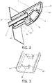
Fig. 1 is a schematic diagram of an external structure of a rear-view mirror of a vehicle of the disclosure; -
Fig. 2 is a schematic diagram of an internal structure of a rear-view mirror of a vehicle of the disclosure; and -
Fig. 3 is a structural diagram of a snap-fit member in a rear-view mirror of a vehicle of the disclosure. - 1. rear-view mirror; 2. laser radar; 3. air supply pipe; 4. snap-fit member; 41. connecting portion; 42. first gripping portion; 43. second gripping portion; 51. accommodating chamber; 52. communicating chamber; 61. first screwing element; and 62. second screwing element.
- The preferred embodiments of the disclosure are described below with reference to the accompanying drawings. It should be understood by those skilled in the art that these embodiments are only for explaining the technical principles of the disclosure and are not intended to limit the scope of protection of the disclosure.
- It should be noted that, in the description of the disclosure, the terms that indicate the direction or positional relationship, such as "middle", "upper", "left", "right", "inner", and "outer", are based on the direction or positional relationship shown in the figures, which is merely for ease of description instead of indicating or implying that the device or element must have a particular orientation and be constructed and operated in a particular orientation, and therefore, should not be construed as limiting the disclosure. Furthermore, the terms "first" and "second" are used for descriptive purposes only, and cannot be understood as indicating or implying relative importance.
- In addition, it should also be noted that, in the description of the disclosure, the terms "arrange", "mount", and "connect" should be interpreted in a broad sense unless explicitly defined and limited otherwise. For example, a connection may be a fixed connection, a detachable connection, or an integral connection; or may mean a direct connection, an indirect connection by means of an intermediary, or internal communication between two elements. For those skilled in the art, the specific meaning of the above-mentioned terms in the disclosure can be interpreted according to the specific situation.
- Based on the problem mentioned in the Background Art that laser radars used for sensing surrounding environments for vehicles have poor heat dissipation, the disclosure provides a rear-view mirror assembly of a vehicle, and a vehicle, and is intended to realize purposeful cooling and heat dissipation of a laser radar using cooling air of an onboard air-conditioner, thereby avoiding the situation that detection precision of the laser radar is affected or detection faults occur due to excessive temperature of the laser radar during use of the laser radar, prolonging service life of the laser radar, and ensuring normal operation of the laser radar.
- Specifically, the vehicle of the disclosure includes a vehicle body and rear-view mirror assemblies. There are two rear-view mirror assemblies. The two rear-view mirror assemblies are respectively located on the left front and the right front of a vehicle body, can be fastened to a door of the vehicle body, and can also be fastened onto other components of the vehicle body. As shown in
Fig. 1 andFig. 2 , the rear-view mirror assembly includes a rear-view mirror 1, alaser radar 2, and anair supply pipe 3. The rear-view mirror 1 is provided with a chamber. Thelaser radar 2 is disposed in the chamber, and a detection part of thelaser radar 2 is exposed to the outside of the rear-view mirror 1. An inlet of theair supply pipe 3 is in communication with an air outlet of the onboard air-conditioner. Theair supply pipe 3 extends into the chamber, and an outlet of theair supply pipe 3 is arranged towards thelaser radar 2. Those skilled in the art can flexibly set a fastening manner of theair supply pipe 3 in the chamber in practical applications. Theair supply pipe 3 may be connected to an inner wall of the rear-view mirror 1 by welding, or theair supply pipe 3 and the rear-view mirror 1 may be integrally cast. Theair supply pipe 3 can also be connected to the inner wall of the rear-view mirror 1 in a detachable manner, for example, theair supply pipe 3 is snap-fitted, magnetically attached, screwed or bonded to the inner wall of the rear-view mirror 1. In addition, theair supply pipe 3 can also be connected to the inner wall of the rear-view mirror 1 through a combination of the above various detachable connection manners. - In a preferred circumstance, the rear-view mirror assembly further includes a snap-fit assembly disposed in the chamber, and the
air supply pipe 3 is connected inside the chamber through the snap-fit assembly. The snap-fit assembly may be a single or a plurality of snap-fit members 4 for mounting the air supply pipe 3 (as the circumference of a plurality of snap-fit members inFig. 2 ). When the plurality of snap-fit members 4 are used to mount theair supply pipe 3, the plurality of snap-fit members 4 can be arranged at intervals from one another, or can be arranged consecutively, wherein the snap-fit members 4 may be made of a plastic material such as PA66 such that the snap-fit members 4 can be mounted and demounted repeatedly without being damaged. The snap-fit members 4 may also be made of other materials in actual applications. Referring toFig. 2 , in a preferred solution, a plurality of snap-fit members 4 are arranged on the inner wall of the rear-view mirror 1, and the plurality of snap-fit members 4 are spaced apart from one another and clamp theair supply pipe 3 in the chamber. - In the above preferred solution, each snap-
fit member 4 of the plurality of snap-fit members 4 may have the same structure, or may have the different structure. The snap-fit member 4 may have a snap-fit structure, or a claw structure, or other clamping structure, as long as it can fasten theair supply pipe 3 to the inner wall of the rear-view mirror 1. In a preferred situation, with continued reference toFig. 2 and Fig. 3 (it should be noted that, in order to clearly illustrate the preferred solution of the snap-fit member of the disclosure, some product structures including theair supply pipe 3 and the like are omitted inFig. 3 , to facilitate illustration of the specific structure of the snap-fit member 4), specifically, each snap-fit member 4 includes a connectingportion 41, a first grippingportion 42 and a second grippingportion 43, the connectingportion 41 is connected to the inner wall of the rear-view mirror 1, the first grippingportion 42 and the second grippingportion 43 are both connected to the connectingportion 41, and theair supply pipe 3 is clamped between the first grippingportion 42 and the second grippingportion 43. With this arrangement, the first grippingportion 42 and the second grippingportion 43 engage and clamp theair supply pipe 3 on both sides respectively, so as to prevent theair supply pipe 3 from moving due to unstable mounting. As shown inFig. 3 , it is more preferred that one end of the first grippingportion 42 and one end of the second grippingportion 43 are both connected to the connectingportion 41, there is a gap between the other end of the first grippingportion 42 and the other end of the second grippingportion 43, and a width of the gap is less than a diameter of theair supply pipe 3; moreover, the first grippingportion 42 and the second grippingportion 43 are both elastic gripping portions which may provide a pre-tightening force that can fasten and connect theair supply pipe 3, moreover, the arrangement of the elastic gripping portions can be freely deformed and facilitates demounting and maintenance of theair supply pipe 3. As an alternative, the first grippingportion 42 and the second grippingportion 43 may also be inelastic gripping portions, or one is an elastic gripping portion and the other is an inelastic gripping portion. The adjustment of a specific type of the gripping portion does not constitute a limitation to the disclosure, and should be limited within the scope of protection of the disclosure. - Optionally, the chamber may be divided into an accommodating chamber and a communicating chamber, which are respectively used for accommodating different components. For example, the
air supply pipe 3 is mounted in the communicatingchamber 52, and thelaser radar 2 is mounted in theaccommodating chamber 51. However, the arrangement of the above-mentioned chambers is merely an example, not a limitation. There may be only one chamber or the chamber may be divided into three or more chambers, and the specific arrangement positions of theair supply pipe 3 and thelaser radar 2 can be flexibly arranged according to the number of the chambers. Those skilled in the art can flexibly set a fastening manner of thelaser radar 2 in the chamber in practical applications. Thelaser radar 2 may be connected to the inner wall of the rear-view mirror 1 by welding, or the laser radar and the rear-view mirror 1 may be integrally cast. Moreover, thelaser radar 2 can also be connected to the inner wall of the rear-view mirror 1 in a detachable manner, for example, thelaser radar 2 is screwed, magnetically attached, snap-fitted or bonded to the inner wall of the rear-view mirror 1. - Referring to
Fig. 2 , in a preferred solution, anaccommodating chamber 51 and a communicatingchamber 52 are respectively formed in an inner cavity of the rear-view mirror assembly. Thelaser radar 2 is arranged in theaccommodating chamber 51, theair supply pipe 3 is arranged in the communicatingchamber 52, theaccommodating chamber 51 is in communication with the interior of a body of the vehicle through theaccommodating chamber 52, a part of the snap-fit members 4 is arranged in theaccommodating chamber 51, and the other part of the snap-fit members 4 is arranged in the communicatingchamber 52, or all of the snap-fit members 4 may be arranged in theaccommodating chamber 51, or all of the snap-fit members 4 may be arranged in the communicatingchamber 52. In a preferred circumference, the rear-view mirror assembly further includes a connecting member arranged in theaccommodating chamber 51, and thelaser radar 2 is connected into theaccommodating chamber 51 through the connecting member. The connecting member can be selected from a screwing element or a riveting element. Continuing to refer toFig. 2 , preferably, the connecting member between thelaser radar 2 and theaccommodating chamber 51 is a screwing element, and a through hole is formed on the outside of thelaser radar 2 for the screwing element to pass through thelaser radar 2 and fasten it. The overall material of the screwing element may be an aluminum alloy, alloy steel and other metal material. Preferably, the connecting member includes a first screwingelement 61 and a second screwingelement 62, thelaser radar 2 is fastened to the inner wall of theaccommodating chamber 51 by means of the two screwing elements, and the first screwingelement 61 and the second screwingelement 62 are respectively located on both sides of thelaser radar 2. - In the disclosure, the number of
laser radars 2 may be one or more. For example, in the structure that the chamber is divided into theaccommodating chamber 51 and the communicatingchamber 52, a plurality oflaser radars 2 may be arranged in theaccommodating chamber 51. Thelaser radars 2 may be arranged centrally or dispersedly. When thelaser radars 2 are dispersedly arranged in theaccommodating chamber 51, a bore diameter of the outlet of theair supply pipe 3 can be increased to expand an air supply area, internal temperature of theaccommodating chamber 51 is lowered by cooling air of the onboard air-conditioner so that a cooler space is formed to cool down thelaser radars 2 in theaccommodating chamber 51. In the above, the arrangement of all thelaser radars 2 in theaccommodating chamber 51 is only exemplary, and those skilled in the art can flexibly adjust the structure of theair supply pipe 3 according to the specific structure and dividing manner of the chamber, as long as all thelaser radars 2 can be cooled by outlet air from theair supply pipe 3. The variation of this structure does not depart from the technical concept of the disclosure, and should be limited within the scope of protection of the disclosure. - In the above preferred solution, the
air supply pipe 3 may be a flexible pipe, for example, theair supply pipe 3 may be a soft plastic pipe or a rubber pipe, and the flexible pipe with high ductility can be applied to a circumstance that needs to be foldable or non-foldable. Those skilled in the art can also understand that when the rear-view mirror 1 is of a non-foldable structure, theair supply pipe 3 may also be a rigid pipe. Those skilled in the art could flexibly select a material for making theair supply pipe 3 in practical applications. As shown inFig. 2 , theair supply pipe 3 is a flexible pipe. The inlet of theair supply pipe 3 is in communication with the air outlet of the onboard air-conditioner so that cooling air generated by the onboard air-conditioner may enter theair supply pipe 3. Theair supply 3 extends into the communicatingchamber 52 and theaccommodating chamber 51 and the outlet of theair supply pipe 3 is arranged towards thelaser radar 2, so that cooling air delivered from the onboard air-conditioner may directly reach theaccommodating chamber 51 through theair supply pipe 3 to purposefully cool thelaser radar 2. - Heretofore, the technical solutions of the disclosure have been described in conjunction with the preferred embodiments shown in the drawings, however, those skilled in the art can readily understand that the scope of protection of the disclosure is obviously not limited to these specific embodiments. Those skilled in the art could make equivalent changes or substitutions to the related technical features without departing from the principles of the disclosure, and all the technical solutions after the changes or the substitutions fall within the scope of protection of the disclosure.
Claims (10)
- A rear-view mirror assembly of a vehicle, which vehicle comprises an onboard air-conditioner, the rear-view mirror assembly comprising a rear-view mirror, a laser radar, and an air supply pipe, wherein the rear-view mirror is provided with a chamber, the laser radar is disposed in the chamber and a detection part of the laser radar is exposed to the outside of the rear-view mirror, an inlet of the air supply pipe is in communication with an air outlet of the onboard air-conditioner, the air supply pipe extends into the chamber, and an outlet of the air supply pipe is arranged towards the laser radar.
- The rear-view mirror assembly according to claim 1, further comprising a snap-fit assembly disposed in the chamber, the air supply pipe being connected inside the chamber through the snap-fit assembly.
- The rear-view mirror assembly according to claim 2, wherein the snap-fit assembly comprises a plurality of snap-fit members, the plurality of snap-fit members being arranged at intervals from one another and clamping the air supply pipe in the chamber.
- The rear-view mirror assembly according to claim 3, wherein each of the snap-fit members comprises a connecting portion, a first gripping portion, and a second gripping portion, the connecting portion is connected to an inner wall of the rear-view mirror, the first gripping portion and the second gripping portion are both connected to the connecting portion, and the air supply pipe is clamped between the first gripping portion and the second gripping portion.
- The rear-view mirror assembly according to claim 4, wherein both the first gripping portion and the second gripping portion are elastic gripping portions, one end of the first gripping portion and one end of the second gripping portion are both connected to the connecting portion, there is a gap between the other end of the first gripping portion and the other end of the second gripping portion, and a width of the gap is less than a diameter of the air supply pipe.
- The rear-view mirror assembly according to claim 3, wherein the chamber comprises an accommodating chamber and a communicating chamber, the laser radar is arranged in the accommodating chamber, the accommodating chamber is in communication with the interior of a body of the vehicle through the communicating chamber, a part of the snap-fit members are arranged in the accommodating chamber, and the other part of the snap-fit members are arranged in the communicating chamber.
- The rear-view mirror assembly according to claim 1, further comprising a connecting member, the laser radar being connected to an inner wall of the rear-view mirror through the connecting member.
- The rear-view mirror assembly according to claim 7, wherein the connecting member comprises a first screwing element and a second screwing element, the laser radar is connected to the inner wall of the rear-view mirror through the first screwing element and the second screwing element, and the first screwing element and the second screwing element are respectively located on two sides of the laser radar.
- The rear-view mirror assembly according to any one of claims 1 to 8, wherein the number of the laser radar is more than one, and/or
the air supply pipe is a flexible pipe. - A vehicle, comprising the rear-view mirror assembly according to any one of claims 1 to 9.
Applications Claiming Priority (1)
| Application Number | Priority Date | Filing Date | Title |
|---|---|---|---|
| CN202121560590.5U CN215398441U (en) | 2021-07-09 | 2021-07-09 | Automobile rearview mirror assembly and automobile |
Publications (2)
| Publication Number | Publication Date |
|---|---|
| EP4116148A1 true EP4116148A1 (en) | 2023-01-11 |
| EP4116148B1 EP4116148B1 (en) | 2025-07-09 |
Family
ID=79648163
Family Applications (1)
| Application Number | Title | Priority Date | Filing Date |
|---|---|---|---|
| EP22165322.3A Active EP4116148B1 (en) | 2021-07-09 | 2022-03-30 | Rear-view mirror assembly of vehicle, and vehicle |
Country Status (3)
| Country | Link |
|---|---|
| US (1) | US20230009500A1 (en) |
| EP (1) | EP4116148B1 (en) |
| CN (1) | CN215398441U (en) |
Citations (4)
| Publication number | Priority date | Publication date | Assignee | Title |
|---|---|---|---|---|
| CN201432615Y (en) * | 2009-07-16 | 2010-03-31 | 张国玉 | Water-removed rearview mirror of automobile |
| FR2943123A1 (en) * | 2009-03-16 | 2010-09-17 | Peugeot Citroen Automobiles Sa | Monoblock cooling assembly for e.g. exterior temperature sensor in outside rearview mirror of motor vehicle, has ducts connecting hot and cold heating exchanging zones for circulating heat transfer fluid between zones |
| CN210591624U (en) * | 2019-09-17 | 2020-05-22 | 瑞安市联众汽车零部件有限公司 | A car rearview mirror |
| CN112208440A (en) * | 2020-09-23 | 2021-01-12 | 东风商用车有限公司 | Commercial vehicle rearview mirror structure integrated with automobile auxiliary driving system |
Family Cites Families (2)
| Publication number | Priority date | Publication date | Assignee | Title |
|---|---|---|---|---|
| US7796081B2 (en) * | 1997-10-22 | 2010-09-14 | Intelligent Technologies International, Inc. | Combined imaging and distance monitoring for vehicular applications |
| US6767033B2 (en) * | 2002-10-28 | 2004-07-27 | Lloyd Herbert King, Jr. | Pipe saddle |
-
2021
- 2021-07-09 CN CN202121560590.5U patent/CN215398441U/en active Active
-
2022
- 2022-03-30 EP EP22165322.3A patent/EP4116148B1/en active Active
- 2022-07-08 US US17/860,230 patent/US20230009500A1/en not_active Abandoned
Patent Citations (4)
| Publication number | Priority date | Publication date | Assignee | Title |
|---|---|---|---|---|
| FR2943123A1 (en) * | 2009-03-16 | 2010-09-17 | Peugeot Citroen Automobiles Sa | Monoblock cooling assembly for e.g. exterior temperature sensor in outside rearview mirror of motor vehicle, has ducts connecting hot and cold heating exchanging zones for circulating heat transfer fluid between zones |
| CN201432615Y (en) * | 2009-07-16 | 2010-03-31 | 张国玉 | Water-removed rearview mirror of automobile |
| CN210591624U (en) * | 2019-09-17 | 2020-05-22 | 瑞安市联众汽车零部件有限公司 | A car rearview mirror |
| CN112208440A (en) * | 2020-09-23 | 2021-01-12 | 东风商用车有限公司 | Commercial vehicle rearview mirror structure integrated with automobile auxiliary driving system |
Also Published As
| Publication number | Publication date |
|---|---|
| CN215398441U (en) | 2022-01-04 |
| EP4116148B1 (en) | 2025-07-09 |
| US20230009500A1 (en) | 2023-01-12 |
Similar Documents
| Publication | Publication Date | Title |
|---|---|---|
| US8087315B2 (en) | Methods and systems for attaching and detaching a payload device to and from, respectively, a gimbal system without requiring use of a mechanical tool | |
| US20120081550A1 (en) | Camera system | |
| CN107921997B (en) | Electric drive device and electric power steering device | |
| CN107921998B (en) | Electric drive and electric power steering | |
| US8444215B2 (en) | Housing for the radiator blind of a motor vehicle | |
| US4196775A (en) | Shock-mounted, liquid cooled cold plate assembly | |
| US20190382133A1 (en) | Unmanned aerial vehicle | |
| CN108290603B (en) | Electric drive and electric power steering | |
| WO2017154498A1 (en) | Electric drive device and electric power steering device | |
| WO2017154499A1 (en) | Electric drive device and electric power steering device | |
| CN110891171B (en) | Test module for fixed focus camera module evaluation | |
| US20220146337A1 (en) | Measurement system for installation between torque and/or force-transmitting machine parts | |
| US10385757B2 (en) | Cooling device for an internal combustion engine of a motor vehicle | |
| EP4116148A1 (en) | Rear-view mirror assembly of vehicle, and vehicle | |
| US20160308341A1 (en) | Electrical junction box and wire harness | |
| CN111048706B (en) | Vehicle-mounted power battery assembly and new energy vehicle | |
| US11547026B2 (en) | Electric vehicle and power converter thereof | |
| WO2018143079A1 (en) | Battery pack | |
| EP1596075A1 (en) | Three-dimensionally adjustable mounting device | |
| EP0492287B1 (en) | System for attaching a bracket to two separate parts of a mechanism, in particular the block and head of an internal combustion engine | |
| CN116685864A (en) | Adjusting device for adjusting the position of a sensor module, vehicle component and method for adjusting the position of a sensor module | |
| US20240262164A1 (en) | Thermal management module | |
| US20240263664A1 (en) | Washer and Screw Connection System | |
| US20260029062A1 (en) | Flow path forming device | |
| CN111315643A (en) | Indexing system for parts |
Legal Events
| Date | Code | Title | Description |
|---|---|---|---|
| PUAI | Public reference made under article 153(3) epc to a published international application that has entered the european phase |
Free format text: ORIGINAL CODE: 0009012 |
|
| STAA | Information on the status of an ep patent application or granted ep patent |
Free format text: STATUS: THE APPLICATION HAS BEEN PUBLISHED |
|
| AK | Designated contracting states |
Kind code of ref document: A1 Designated state(s): AL AT BE BG CH CY CZ DE DK EE ES FI FR GB GR HR HU IE IS IT LI LT LU LV MC MK MT NL NO PL PT RO RS SE SI SK SM TR |
|
| STAA | Information on the status of an ep patent application or granted ep patent |
Free format text: STATUS: REQUEST FOR EXAMINATION WAS MADE |
|
| 17P | Request for examination filed |
Effective date: 20230629 |
|
| RBV | Designated contracting states (corrected) |
Designated state(s): AL AT BE BG CH CY CZ DE DK EE ES FI FR GB GR HR HU IE IS IT LI LT LU LV MC MK MT NL NO PL PT RO RS SE SI SK SM TR |
|
| STAA | Information on the status of an ep patent application or granted ep patent |
Free format text: STATUS: EXAMINATION IS IN PROGRESS |
|
| 17Q | First examination report despatched |
Effective date: 20240717 |
|
| GRAP | Despatch of communication of intention to grant a patent |
Free format text: ORIGINAL CODE: EPIDOSNIGR1 |
|
| STAA | Information on the status of an ep patent application or granted ep patent |
Free format text: STATUS: GRANT OF PATENT IS INTENDED |
|
| INTG | Intention to grant announced |
Effective date: 20250312 |
|
| GRAS | Grant fee paid |
Free format text: ORIGINAL CODE: EPIDOSNIGR3 |
|
| GRAA | (expected) grant |
Free format text: ORIGINAL CODE: 0009210 |
|
| STAA | Information on the status of an ep patent application or granted ep patent |
Free format text: STATUS: THE PATENT HAS BEEN GRANTED |
|
| AK | Designated contracting states |
Kind code of ref document: B1 Designated state(s): AL AT BE BG CH CY CZ DE DK EE ES FI FR GB GR HR HU IE IS IT LI LT LU LV MC MK MT NL NO PL PT RO RS SE SI SK SM TR |
|
| REG | Reference to a national code |
Ref country code: GB Ref legal event code: FG4D |
|
| REG | Reference to a national code |
Ref country code: CH Ref legal event code: EP |
|
| REG | Reference to a national code |
Ref country code: IE Ref legal event code: FG4D |
|
| REG | Reference to a national code |
Ref country code: DE Ref legal event code: R096 Ref document number: 602022017169 Country of ref document: DE |
|
| REG | Reference to a national code |
Ref country code: NL Ref legal event code: MP Effective date: 20250709 |
|
| PG25 | Lapsed in a contracting state [announced via postgrant information from national office to epo] |
Ref country code: PT Free format text: LAPSE BECAUSE OF FAILURE TO SUBMIT A TRANSLATION OF THE DESCRIPTION OR TO PAY THE FEE WITHIN THE PRESCRIBED TIME-LIMIT Effective date: 20251110 |
|
| PG25 | Lapsed in a contracting state [announced via postgrant information from national office to epo] |
Ref country code: NL Free format text: LAPSE BECAUSE OF FAILURE TO SUBMIT A TRANSLATION OF THE DESCRIPTION OR TO PAY THE FEE WITHIN THE PRESCRIBED TIME-LIMIT Effective date: 20250709 |
|
| REG | Reference to a national code |
Ref country code: AT Ref legal event code: MK05 Ref document number: 1811590 Country of ref document: AT Kind code of ref document: T Effective date: 20250709 |
|
| PG25 | Lapsed in a contracting state [announced via postgrant information from national office to epo] |
Ref country code: IS Free format text: LAPSE BECAUSE OF FAILURE TO SUBMIT A TRANSLATION OF THE DESCRIPTION OR TO PAY THE FEE WITHIN THE PRESCRIBED TIME-LIMIT Effective date: 20251109 |
|
| PG25 | Lapsed in a contracting state [announced via postgrant information from national office to epo] |
Ref country code: NO Free format text: LAPSE BECAUSE OF FAILURE TO SUBMIT A TRANSLATION OF THE DESCRIPTION OR TO PAY THE FEE WITHIN THE PRESCRIBED TIME-LIMIT Effective date: 20251009 |
|
| REG | Reference to a national code |
Ref country code: LT Ref legal event code: MG9D |
|
| PG25 | Lapsed in a contracting state [announced via postgrant information from national office to epo] |
Ref country code: AT Free format text: LAPSE BECAUSE OF FAILURE TO SUBMIT A TRANSLATION OF THE DESCRIPTION OR TO PAY THE FEE WITHIN THE PRESCRIBED TIME-LIMIT Effective date: 20250709 |
|
| PG25 | Lapsed in a contracting state [announced via postgrant information from national office to epo] |
Ref country code: FI Free format text: LAPSE BECAUSE OF FAILURE TO SUBMIT A TRANSLATION OF THE DESCRIPTION OR TO PAY THE FEE WITHIN THE PRESCRIBED TIME-LIMIT Effective date: 20250709 |
|
| PG25 | Lapsed in a contracting state [announced via postgrant information from national office to epo] |
Ref country code: HR Free format text: LAPSE BECAUSE OF FAILURE TO SUBMIT A TRANSLATION OF THE DESCRIPTION OR TO PAY THE FEE WITHIN THE PRESCRIBED TIME-LIMIT Effective date: 20250709 |
|
| PG25 | Lapsed in a contracting state [announced via postgrant information from national office to epo] |
Ref country code: GR Free format text: LAPSE BECAUSE OF FAILURE TO SUBMIT A TRANSLATION OF THE DESCRIPTION OR TO PAY THE FEE WITHIN THE PRESCRIBED TIME-LIMIT Effective date: 20251010 |
|
| PG25 | Lapsed in a contracting state [announced via postgrant information from national office to epo] |
Ref country code: SE Free format text: LAPSE BECAUSE OF FAILURE TO SUBMIT A TRANSLATION OF THE DESCRIPTION OR TO PAY THE FEE WITHIN THE PRESCRIBED TIME-LIMIT Effective date: 20250709 |
|
| PG25 | Lapsed in a contracting state [announced via postgrant information from national office to epo] |
Ref country code: LV Free format text: LAPSE BECAUSE OF FAILURE TO SUBMIT A TRANSLATION OF THE DESCRIPTION OR TO PAY THE FEE WITHIN THE PRESCRIBED TIME-LIMIT Effective date: 20250709 |
|
| PG25 | Lapsed in a contracting state [announced via postgrant information from national office to epo] |
Ref country code: PL Free format text: LAPSE BECAUSE OF FAILURE TO SUBMIT A TRANSLATION OF THE DESCRIPTION OR TO PAY THE FEE WITHIN THE PRESCRIBED TIME-LIMIT Effective date: 20250709 Ref country code: BG Free format text: LAPSE BECAUSE OF FAILURE TO SUBMIT A TRANSLATION OF THE DESCRIPTION OR TO PAY THE FEE WITHIN THE PRESCRIBED TIME-LIMIT Effective date: 20250709 |
|
| PG25 | Lapsed in a contracting state [announced via postgrant information from national office to epo] |
Ref country code: RS Free format text: LAPSE BECAUSE OF FAILURE TO SUBMIT A TRANSLATION OF THE DESCRIPTION OR TO PAY THE FEE WITHIN THE PRESCRIBED TIME-LIMIT Effective date: 20251009 |
|
| PG25 | Lapsed in a contracting state [announced via postgrant information from national office to epo] |
Ref country code: ES Free format text: LAPSE BECAUSE OF FAILURE TO SUBMIT A TRANSLATION OF THE DESCRIPTION OR TO PAY THE FEE WITHIN THE PRESCRIBED TIME-LIMIT Effective date: 20250709 |
|
| PG25 | Lapsed in a contracting state [announced via postgrant information from national office to epo] |
Ref country code: SM Free format text: LAPSE BECAUSE OF FAILURE TO SUBMIT A TRANSLATION OF THE DESCRIPTION OR TO PAY THE FEE WITHIN THE PRESCRIBED TIME-LIMIT Effective date: 20250709 |
|
| PGFP | Annual fee paid to national office [announced via postgrant information from national office to epo] |
Ref country code: GB Payment date: 20260324 Year of fee payment: 5 |
|
| PG25 | Lapsed in a contracting state [announced via postgrant information from national office to epo] |
Ref country code: DK Free format text: LAPSE BECAUSE OF FAILURE TO SUBMIT A TRANSLATION OF THE DESCRIPTION OR TO PAY THE FEE WITHIN THE PRESCRIBED TIME-LIMIT Effective date: 20250709 |
|
| PGFP | Annual fee paid to national office [announced via postgrant information from national office to epo] |
Ref country code: DE Payment date: 20260319 Year of fee payment: 5 |
|
| PG25 | Lapsed in a contracting state [announced via postgrant information from national office to epo] |
Ref country code: IT Free format text: LAPSE BECAUSE OF FAILURE TO SUBMIT A TRANSLATION OF THE DESCRIPTION OR TO PAY THE FEE WITHIN THE PRESCRIBED TIME-LIMIT Effective date: 20250709 |
|
| PGFP | Annual fee paid to national office [announced via postgrant information from national office to epo] |
Ref country code: FR Payment date: 20260323 Year of fee payment: 5 |
|
| PG25 | Lapsed in a contracting state [announced via postgrant information from national office to epo] |
Ref country code: CZ Free format text: LAPSE BECAUSE OF FAILURE TO SUBMIT A TRANSLATION OF THE DESCRIPTION OR TO PAY THE FEE WITHIN THE PRESCRIBED TIME-LIMIT Effective date: 20250709 |
|
| PG25 | Lapsed in a contracting state [announced via postgrant information from national office to epo] |
Ref country code: SK Free format text: LAPSE BECAUSE OF FAILURE TO SUBMIT A TRANSLATION OF THE DESCRIPTION OR TO PAY THE FEE WITHIN THE PRESCRIBED TIME-LIMIT Effective date: 20250709 Ref country code: EE Free format text: LAPSE BECAUSE OF FAILURE TO SUBMIT A TRANSLATION OF THE DESCRIPTION OR TO PAY THE FEE WITHIN THE PRESCRIBED TIME-LIMIT Effective date: 20250709 |