EP4116147A1 - Cancel cam - Google Patents
Cancel cam Download PDFInfo
- Publication number
- EP4116147A1 EP4116147A1 EP21764307.1A EP21764307A EP4116147A1 EP 4116147 A1 EP4116147 A1 EP 4116147A1 EP 21764307 A EP21764307 A EP 21764307A EP 4116147 A1 EP4116147 A1 EP 4116147A1
- Authority
- EP
- European Patent Office
- Prior art keywords
- reinforcing rib
- cam
- axial length
- wall
- cam wall
- Prior art date
- Legal status (The legal status is an assumption and is not a legal conclusion. Google has not performed a legal analysis and makes no representation as to the accuracy of the status listed.)
- Granted
Links
Images






Classifications
-
- B—PERFORMING OPERATIONS; TRANSPORTING
- B60—VEHICLES IN GENERAL
- B60Q—ARRANGEMENT OF SIGNALLING OR LIGHTING DEVICES, THE MOUNTING OR SUPPORTING THEREOF OR CIRCUITS THEREFOR, FOR VEHICLES IN GENERAL
- B60Q1/00—Arrangement of optical signalling or lighting devices, the mounting or supporting thereof or circuits therefor
- B60Q1/26—Arrangement of optical signalling or lighting devices, the mounting or supporting thereof or circuits therefor the devices being primarily intended to indicate the vehicle, or parts thereof, or to give signals, to other traffic
- B60Q1/34—Arrangement of optical signalling or lighting devices, the mounting or supporting thereof or circuits therefor the devices being primarily intended to indicate the vehicle, or parts thereof, or to give signals, to other traffic for indicating change of drive direction
- B60Q1/40—Arrangement of optical signalling or lighting devices, the mounting or supporting thereof or circuits therefor the devices being primarily intended to indicate the vehicle, or parts thereof, or to give signals, to other traffic for indicating change of drive direction having mechanical, electric or electronic automatic return to inoperative position
- B60Q1/42—Arrangement of optical signalling or lighting devices, the mounting or supporting thereof or circuits therefor the devices being primarily intended to indicate the vehicle, or parts thereof, or to give signals, to other traffic for indicating change of drive direction having mechanical, electric or electronic automatic return to inoperative position having mechanical automatic return to inoperative position due to steering-wheel position, e.g. with roller wheel control
-
- B—PERFORMING OPERATIONS; TRANSPORTING
- B60—VEHICLES IN GENERAL
- B60Q—ARRANGEMENT OF SIGNALLING OR LIGHTING DEVICES, THE MOUNTING OR SUPPORTING THEREOF OR CIRCUITS THEREFOR, FOR VEHICLES IN GENERAL
- B60Q1/00—Arrangement of optical signalling or lighting devices, the mounting or supporting thereof or circuits therefor
- B60Q1/26—Arrangement of optical signalling or lighting devices, the mounting or supporting thereof or circuits therefor the devices being primarily intended to indicate the vehicle, or parts thereof, or to give signals, to other traffic
- B60Q1/34—Arrangement of optical signalling or lighting devices, the mounting or supporting thereof or circuits therefor the devices being primarily intended to indicate the vehicle, or parts thereof, or to give signals, to other traffic for indicating change of drive direction
- B60Q1/40—Arrangement of optical signalling or lighting devices, the mounting or supporting thereof or circuits therefor the devices being primarily intended to indicate the vehicle, or parts thereof, or to give signals, to other traffic for indicating change of drive direction having mechanical, electric or electronic automatic return to inoperative position
- B60Q1/42—Arrangement of optical signalling or lighting devices, the mounting or supporting thereof or circuits therefor the devices being primarily intended to indicate the vehicle, or parts thereof, or to give signals, to other traffic for indicating change of drive direction having mechanical, electric or electronic automatic return to inoperative position having mechanical automatic return to inoperative position due to steering-wheel position, e.g. with roller wheel control
- B60Q1/425—Arrangement of optical signalling or lighting devices, the mounting or supporting thereof or circuits therefor the devices being primarily intended to indicate the vehicle, or parts thereof, or to give signals, to other traffic for indicating change of drive direction having mechanical, electric or electronic automatic return to inoperative position having mechanical automatic return to inoperative position due to steering-wheel position, e.g. with roller wheel control using a latching element for resetting a switching element
-
- B—PERFORMING OPERATIONS; TRANSPORTING
- B60—VEHICLES IN GENERAL
- B60Y—INDEXING SCHEME RELATING TO ASPECTS CROSS-CUTTING VEHICLE TECHNOLOGY
- B60Y2306/00—Other features of vehicle sub-units
- B60Y2306/09—Reducing noise
Definitions
- the technology disclosed in the present application relates to a cancel cam.
- Patent Documents 1 and 2 describe a cancel cam used in a rotary connector device.
- An object of the technology disclosed in the present application is to ensure the mechanical strength of the cancel cam and reduce the abnormal noise generated by the contact between the turn signal switch and the cancel cam.
- a cancel cam includes an annular member, a cam wall, and at least one reinforcing rib.
- the annular member is a member rotatable integrally with a steering shaft about a rotation axis and includes an outer peripheral portion, an inner peripheral portion, and a first surface which faces in an axial direction parallel to the rotation axis.
- the cam wall is configured to return the turn signal switch from an operating position to a neutral position, and the cam wall extends from the outer peripheral portion in an axial direction and extends along the outer peripheral portion in a circumferential direction.
- the at least one reinforcing rib extends from the cam wall toward the inner peripheral portion and couples the cam wall to the annular member.
- the cam wall has a first axial length defined from the first surface in the axial direction.
- the inner peripheral portion has a second axial length defined from the first surface in the axial direction. The second axial length is shorter than the first axial length.
- the second axial length is shorter than the first axial length, and thus it is possible to suppress the reverberation of abnormal noise generated by the contact between the turn signal switch and the cam wall on an inner side in a radial direction of the cam wall.
- the coupling strength between the annular member and the cam wall can be ensured by the at least one reinforcing rib. This makes it possible to ensure the mechanical strength of the cancel cam and reduce the abnormal noise generated by the contact between the turn signal switch and the cancel cam.
- the cancel cam according to a second aspect is the cancel cam according to the first aspect, wherein the annular member does not have a portion protruding in the axial direction from the first surface in the inner peripheral portion.
- the cancel cam according to a third aspect is the cancel cam according to the first or second aspect, wherein the at least one reinforcing rib extends from the cam wall toward the inner peripheral portion and couples the cam wall to the first surface.
- the coupling strength between the annular member and the cam wall can be increased.
- the cancel cam according to a fourth aspect is the cancel cam according to any one of the first to third aspects, wherein the at least one reinforcing rib includes an inclined surface which extends from the cam wall toward the first surface and is inclined with respect to the rotation axis.
- cancel cam it is possible to increase the coupling strength between the annular member and the cam wall and suppress the reverberation of the abnormal noise generated by the contact between the turn signal switch and the cam wall on the inner side in the radial direction of the cam wall.
- the cancel cam according to a fifth aspect is the cancel cam according to any one of the first to fourth aspects, wherein the at least one reinforcing rib has a third axial length defined from the first surface in the axial direction.
- the second axial length is shorter than the third axial length.
- cancel cam it is possible to reliably suppress the reverberation of the abnormal noise generated by the contact between the turn signal switch and the cam wall on the inner side in the radial direction of the cam wall.
- the cancel cam according to a sixth aspect is the cancel cam according to the fifth aspect, wherein the third axial length is equal to or shorter than the first axial length.
- the cancel cam according to a seventh aspect is the cancel cam according to the fifth or sixth aspect, wherein the at least one reinforcing rib has a radial length defined from the cam wall in the radial direction. The radial length is shorter than the third axial length.
- cancel cam according to the seventh aspect it is possible to suppress the generation of the abnormal noise and reduce the weight of the cancel cam.
- the cancel cam according to an eighth aspect is the cancel cam according to any one of the first to seventh aspects, wherein the at least one reinforcing rib includes a plurality of reinforcing ribs.
- cancel cam it is possible to reliably increase the coupling strength between the annular member and the cam wall and suppress the reverberation of the abnormal noise generated by the contact between the turn signal switch and the cam wall on the inner side in the radial direction of the cam wall.
- the cancel cam according to a ninth aspect is the cancel cam according to any one of the first to eighth aspects, wherein the cam wall includes a first circumferential end and a second circumferential end.
- the cam wall extends from the first circumferential end to the second circumferential end in the circumferential direction.
- the cancel cam according to a tenth aspect is the cancel cam according to any one of the first to ninth aspects, wherein the at least one reinforcing rib includes a first reinforcing rib which is coupled to the first circumferential end and a second reinforcing rib which is coupled to the second circumferential end.
- the mechanical strength of the cam wall can be increased.
- the cancel cam according to an eleventh aspect is the cancel cam according to the tenth aspect, wherein the at least one reinforcing rib includes an intermediate reinforcing rib which is disposed between the first reinforcing rib and the second reinforcing rib.
- the thickness of at least one of the first reinforcing rib and the second reinforcing rib is greater than the thickness of the intermediate reinforcing rib.
- At least one of the first circumferential end and the second circumferential end of the cam wall can be efficiently reinforced by at least one of the first reinforcing rib and the second reinforcing rib, and the intermediate portion of the cam wall can be reinforced by the intermediate reinforcing rib.
- the mechanical strength of the cam wall can be efficiently increased by the first reinforcing rib, the second reinforcing rib, and the intermediate reinforcing rib.
- a rotary connector device 1 comprises a rotator 10, a stator 20, an electrical connector 30, and a cancel cam 40.
- the rotator 10 is provided so as to be rotatable about a rotation axis A1 with respect to the stator 20.
- the stator 20 is configured to be fixed to a vehicle body, and the rotator 10 is configured to be coupled to a steering shaft of a steering wheel.
- the electrical connector 30 and the cancel cam 40 are attached to the rotator 10.
- the rotator 10, the electrical connector 30, and the cancel cam 40 are rotatable integrally with the steering wheel about the rotation axis A1.
- the electrical connector 30 is configured to be electrically connected to, for example, a steering side connector.
- the steering side connector is electrically connected to electric circuits such as switches of the steering wheel and an airbag device.
- the cancel cam 40 comprises an annular member 41, a cam wall 42, and at least one reinforcing rib 43.
- the annular member 41 is rotatable integrally with the steering shaft about the rotation axis A1.
- the annular member 41 includes an outer peripheral portion 44, an inner peripheral portion 45, and a first surface 46.
- the first surface 46 faces in an axial direction D1 which is parallel to the rotation axis A1.
- the outer peripheral portion 44 constitutes the outermost circumference of the annular member 41.
- the inner peripheral portion 45 constitutes the innermost circumference of the annular member 41.
- the annular member 41 includes an opening 47.
- the inner peripheral portion 45 defines at least a portion of the opening 47.
- the cam wall 42 is configured to return a turn signal switch 150 (see FIG. 10 ) from an operating position L or R (see FIG. 10 ) to a neutral position N (see FIG. 10 ).
- the cam wall 42 extends from the outer peripheral portion 44 in the axial direction D1 and extends along the outer peripheral portion 44 in a circumferential direction D2.
- the cam wall 42 includes a first circumferential end 42A and a second circumferential end 42B. The cam wall 42 extends from the first circumferential end 42A to the second circumferential end 42B in the circumferential direction D2.
- the at least one reinforcing rib 43 extends from the cam wall 42 toward the inner peripheral portion 45 and couples the cam wall 42 to the annular member 41.
- the at least one reinforcing rib 43 extends from the cam wall 42 toward the inner peripheral portion 45 and couples the cam wall 42 to the first surface 46.
- the at least one reinforcing rib 43 includes a plurality of reinforcing ribs 43.
- the at least one reinforcing rib 43 includes a first reinforcing rib 43A which is coupled to the first circumferential end 42A and a second reinforcing rib 43B which is coupled to the second circumferential end 42B.
- the at least one reinforcing rib 43 includes at least one intermediate reinforcing rib 43C.
- the at least one intermediate reinforcing rib 43C includes a plurality of intermediate reinforcing ribs 43C.
- the at least one reinforcing rib 43 includes an inclined surface 43D which extends from the cam wall 42 toward the first surface 46 and is inclined with respect to the rotation axis A1.
- the first reinforcing rib 43A includes an inclined surface 43D which extends from the cam wall 42 toward the first surface 46 and is inclined with respect to the rotation axis A1.
- the second reinforcing rib 43B includes an inclined surface 43D which extends from the cam wall 42 toward the first surface 46 and is inclined with respect to the rotation axis A1.
- the intermediate reinforcing rib 43C includes an inclined surface 43D which extends from the cam wall 42 toward the first surface 46 and is inclined with respect to the rotation axis A1.
- the cam wall 42 has a first axial length L1 defined from the first surface 46 in the axial direction D1.
- the inner peripheral portion 45 has a second axial length L2 defined from the first surface 46 in the axial direction D1.
- the at least one reinforcing rib 43 has a third axial length L3 defined from the first surface 46 in the axial direction D1.
- the second axial length L2 is shorter than the first axial length L1.
- the second axial length L2 is shorter than the third axial length L3.
- the third axial length L3 is equal to or shorter than the first axial length L1.
- the third axial length L3 is equal to the first axial length L1.
- the third axial length L3 may be shorter than the first axial length L1.
- the second axial length L2 is 50% or less of the first axial length L1.
- the second axial length L2 is 25% or less of the first axial length L1.
- the second axial length L2 is 50% or less of the third axial length L3.
- the third axial length L3 is 25% or less of the first axial length L1.
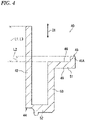
- the annular member 41 does not have a portion protruding in the axial direction D1 from the first surface 46 in the inner peripheral portion 45. That is, in the present embodiment, the second axial length L2 may be zero. However, as illustrated in FIG. 4 , the second axial length L2 may be greater than zero.
- the inner peripheral portion 45 includes a protruding portion 45A which extends from the first surface 46 in the axial direction D1.
- the cam wall 42 includes an outer peripheral surface 42C and an inner peripheral surface 42D.
- the outer peripheral surface 42C is contactable with a turn lever.
- the inner peripheral surface 42D is provided on the back side of the outer peripheral surface 42C.
- the reinforcing rib 43 extends from the inner peripheral surface 42D inward in the radial direction.
- the reinforcing rib 43 extends from a second annular plate 52 in the axial direction D1.
- the reinforcing rib 43 couples the cam wall 42, the second annular plate 52, and an intermediate portion 53.
- the at least one reinforcing rib 43 has a radial length L4 defined from the cam wall 42 in the radial direction.
- the radial length L4 of the reinforcing rib 43 is defined from the inner peripheral surface 42D of the cam wall 42 on the inner side in the radial direction.
- the radial length L4 is shorter than the third axial length L3.
- the radial length L4 may be equal to or longer than the third axial length L3.
- the outer peripheral surface 42C of the cam wall 42 includes a contact surface 42E with which a ratchet 120 (see FIG. 10 ) of the turn signal switch 150 comes in contact.
- the cam wall 42 includes an axial end portion 42F which is farthest from the outer peripheral portion 44 in the axial direction D1.
- the contact surface 42E is provided between the first surface 46 and the axial end portion 42F in the axial direction D1.
- the annular member 41 includes a second surface 49 which faces in the axial direction D1.
- the second surface 49 is provided on the back side of the first surface 46.
- the cancel cam 40 comprises a plurality of coupling portions 50.
- the plurality of coupling portions 50 extend from the second surface 49 in the axial direction D1.
- the coupling portion 50 extends from the inner peripheral portion 45 in the axial direction D1.
- the coupling portion 50 is configured to be coupled to the rotator 10.
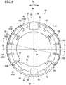
- the cancel cam 40 has a symmetrical shape with respect to a reference plane RP.
- the reference plane RP is a virtual plane including the rotation axis A1.
- the cancel cam 40 comprises a cam wall 142 and at least one reinforcing rib 143.
- the cam wall 142 has a symmetrical shape with respect to the reference plane RP and has substantially the same structure as the cam wall 42.
- the at least one reinforcing rib 143 includes a plurality of reinforcing ribs 143.
- the plurality of reinforcing ribs 143 are symmetrical in shape to the plurality of reinforcing ribs 43 with respect to the reference plane RP and have substantially the same structure as the plurality of reinforcing ribs 43.
- the cancel cam 40 may have an asymmetrical shape with respect to the reference plane RP.
- the intermediate reinforcing rib 43C is disposed between the first reinforcing rib 43A and the second reinforcing rib 43B.
- the thickness of at least one of the first reinforcing rib 43A and the second reinforcing rib 43B is greater than the thickness of the intermediate reinforcing rib 43C.
- the thickness of the first reinforcing rib 43A and the thickness of the second reinforcing rib 43B are greater than the thickness of the intermediate reinforcing ribs 43C.
- the thickness of at least one of the first reinforcing rib 43A and the second reinforcing rib 43B may be equal to the thickness of the intermediate reinforcing rib 43C or may be smaller than the thickness of the intermediate reinforcing rib 43C.
- the annular member 41 includes a first annular plate 51, the second annular plate 52, and the intermediate portion 53.
- the first annular plate 51 includes the inner peripheral portion 45, the first surface 46, and the second surface 49.
- the second annular plate 52 includes the outer peripheral portion 44.
- the coupling portion 50 extends from the first annular plate 51 in the axial direction D1.
- the second annular plate 52 is disposed at a position offset from the first annular plate 51 in the axial direction D1.
- the outer diameter of the second annular plate 52 is greater than the outer diameter of the first annular plate 51.
- the intermediate portion 53 extends from the first annular plate 51 to the second annular plate 52 in the axial direction D1.
- the intermediate portion 53 extends from the second surface 49 of the first annular plate 51 to the second annular plate 52 in the axial direction D1.
- the intermediate portion 53 couples the first annular plate 51 to the second annular plate 52.
- the cam walls 42 and 142 extend from the outer peripheral portion 44 (in the present embodiment, from the outer circumference of the second annular plate 52) beyond the first annular plate 51 in the axial direction D1.
- the cam walls 42 and 142 are disposed on the outer side in the radial direction of the intermediate portion 53.
- the annular member 41 includes a first outer peripheral wall 54 and a second outer peripheral wall 55.
- the first outer peripheral wall 54 extends from the cam wall 42 to the cam wall 142 in the circumferential direction D2.
- the first outer peripheral wall 54 couples the cam wall 42 to the cam wall 142.
- the second outer peripheral wall 55 extends from the cam wall 42 to the cam wall 142 in the circumferential direction D2.
- the second outer peripheral wall 55 couples the cam wall 42 to the cam wall 142.
- the annular member 41 includes a plurality of first ribs 56 and a plurality of second ribs 57.
- the first rib 56 couples the first outer peripheral wall 54 to the second annular plate 52 and the intermediate portion 53.
- the second rib 57 couples the second outer peripheral wall 55 to the second annular plate 52 and the intermediate portion 53.
- first outer peripheral wall 54 and the second outer peripheral wall 55 extend from the outer peripheral portion 44 (in the present embodiment, from the outer circumference of the second annular plate 52) in the axial direction D1.
- the first rib 56 extends from the first outer peripheral wall 54 to the intermediate portion 53.
- the second rib 57 extends from the second outer peripheral wall 55 to the intermediate portion 53.
- the turn signal switch 150 is disposed on the outer side in the radial direction of the cancel cam 40.
- the turn signal switch 150 includes the ratchet 120, a ratchet spring 122, a bracket 130, a back spring 135, a turn lever 140, and a case 151.
- the case 151 is fixed to a vehicle body.
- the ratchet 120, the ratchet spring 122, the bracket 130, and the back spring 135 are provided in the case 151.
- the ratchet 120 is coupled to the case 151 so as to be movable in a moving direction D3 with respect to the case 151.
- the ratchet 120 is provided so as to be contactable with the cam wall 42 of the cancel cam 40.
- the ratchet spring 122 is coupled to the ratchet 120 and the case 151 so as to bias the ratchet 120 toward the cam wall 42.
- the bracket 130 is rotatably coupled to the case 151 by a bracket shaft 131.
- the bracket 130 is rotatable in a first direction D41 and a second direction D42 with respect to the case 151.
- the turn lever 140 is fixed to the bracket 130 and is rotatable with the bracket 130 with respect to the case 151.
- the turn lever 140 and the bracket 130 are rotatable from the neutral position N to the operating position L or R with respect to the case 151.
- the operating position L may also be referred to as a left turn indication position L.
- the operating position R may also be referred to as a right turn indication position R.
- the ratchet 120 includes a ratchet shaft 121, a first ratchet end portion 124, and a second ratchet end portion 125.
- a back plate 134 includes a guide groove 152A.
- the ratchet shaft 121 is disposed in the guide groove 152A.
- the ratchet 120 is guided to the moving direction D3 by the guide groove 152A.
- the ratchet 120 is rotatable about the ratchet shaft 121 with respect to the case 151.
- the first ratchet end portion 124 is contactable with the cam wall 42 of the cancel cam 40.
- the ratchet shaft 121 is disposed between the first ratchet end portion 124 and the second ratchet end portion 125.
- the bracket 130 includes the back plate 134.
- the back plate 134 is provided so as to be movable in a first moving direction C1 and a second moving direction C2 with respect to the case 151.
- the back plate 134 includes a first engagement portion 132, a second engagement portion 133, and a guide portion 136.
- the second ratchet end portion 125 is disposed between the first engagement portion 132 and the second engagement portion 133.
- the guide portion 136 is configured to guide the ratchet 120 to the moving direction D3.
- the guide portion 163 always contacts the ratchet shaft 121 by the biasing force of the ratchet spring 122.
- the guide portion 136 is configured to hold the position of the ratchet 120.
- the ratchet shaft 121 of the ratchet 120 contacts the tip of the guide portion 136. This causes the guide portion 136 to hold the ratchet 120 in a normal position P1.
- the first ratchet end portion 124 of the ratchet 120 is separated from the cancel cam 40.
- the second ratchet end portion 125 of the ratchet 120 is disposed between the first engagement portion 132 and the second engagement portion 133.
- the ratchet shaft 121 moves to a first guide recess portion 137A or a second guide recess portion 137B of the guide portion 136, and the turn lever 140 is held in the operating position L or R.
- the ratchet 120 moves to a contact position P2 where the ratchet 120 is contactable with the cam wall 42 of the cancel cam 40, and the first ratchet end portion 124 collides with the cam wall 42 by the biasing force of the ratchet spring 122. This collision causes abnormal noise.
- the cancel cam 40 comprises the annular member 41, the cam wall 42, and the at least one reinforcing rib 43.
- the annular member 41 is rotatable integrally with a steering shaft about the rotation axis A1, and includes the outer peripheral portion 44, the inner peripheral portion 45, and the first surface 46 which faces in the axial direction D1 parallel to the rotation axis A1.
- the cam wall 42 is configured to return the turn signal switch 150 from the operating position L or R to the neutral position N, and extends from the outer peripheral portion 44 in the axial direction D1 and extends along the outer peripheral portion 44 in the circumferential direction D2.
- the at least one reinforcing rib 43 extends from the cam wall 42 toward the inner peripheral portion 45 and couples the cam wall 42 to the annular member 41.
- the cam wall 42 has the first axial length L1 defined from the first surface 46 in the axial direction D1.
- the inner peripheral portion 45 has the second axial length L2 defined from the first surface 46 in the axial direction D1.
- the second axial length L2 is shorter than the first axial length L1.
- the cancel cam 40 because the second axial length L2 is shorter than the first axial length L1, it is possible to suppress the reverberation of the abnormal noise generated by the contact between the turn signal switch 150 and the cam wall 42 on an inner side in the radial direction of the cam wall 42.
- the coupling strength between the annular member 41 and the cam wall 42 can be ensured by the at least one reinforcing rib 43. This makes it possible to ensure the mechanical strength of the cancel cam 40 and reduce the abnormal noise generated by the contact between the turn signal switch 150 and the cancel cam 40.
- the annular member 41 does not have a portion protruding in the axial direction D1 from the first surface 46 in the inner peripheral portion 45. This makes it possible to reliably suppress the reverberation of the abnormal noise generated by the contact between the turn signal switch 150 and the cam wall 42 on the inner side in the radial direction of the cam wall 42.
- the at least one reinforcing rib 43 extends from the cam wall 42 toward the inner peripheral portion 45 and couples the cam wall 42 to the first surface 46. This allows the increase of the coupling strength between the annular member 41 and the cam wall 42.
- the at least one reinforcing rib 43 includes the inclined surface 43D which extends from the cam wall 42 toward the first surface 46 and is inclined with respect to the rotation axis A1. This makes it possible to increase the coupling strength between the annular member 41 and the cam wall 42 and suppress the reverberation of the abnormal noise generated by the contact between the turn signal switch 150 and the cam wall 42 on the inner side in the radial direction of the cam wall 42.
- the at least one reinforcing rib 43 has the third axial length L3 defined from the first surface 46 in the axial direction D1.
- the second axial length L2 is shorter than the third axial length L3. This makes it possible to reliably suppress the reverberation of the abnormal noise generated by the contact between the turn signal switch 150 and the cam wall 42 on the inner side in the radial direction of the cam wall 42.
- the third axial length L3 is equal to or shorter than the first axial length L1. This makes it possible to suppress the generation of the abnormal noise and reduce the weight of the cancel cam 40.
- the at least one reinforcing rib 43 has the radial length L4 defined from the cam wall 42 in the radial direction.
- the radial length L4 is shorter than the third axial length L3. This makes it possible to suppress the generation of the abnormal noise and reduce the weight of the cancel cam 40.
- the at least one reinforcing rib 43 includes a plurality of reinforcing ribs 43. This makes it possible to increase the coupling strength between the annular member 41 and the cam wall 42 and suppress the reverberation of the abnormal noise generated by the contact between the turn signal switch 150 and the cam wall 42 on the inner side in the radial direction of the cam wall 42.
- the cam wall 42 includes the first circumferential end 42A and the second circumferential end 42B.
- the cam wall 42 extends from the first circumferential end 42A to the second circumferential end 42B in the circumferential direction D2. This makes it easier to ensure the mechanical strength of the cam wall 42.
- the at least one reinforcing rib 43 includes the first reinforcing rib 43A which is coupled to the first circumferential end 42A and the second reinforcing rib 43B which is coupled to the second circumferential end 42B. This allows the increase of the mechanical strength of the cam wall 42.
- the at least one reinforcing rib 43 includes the intermediate reinforcing rib 43C disposed between the first reinforcing rib 43A and the second reinforcing rib 43B.
- the thickness of at least one of the first reinforcing rib 43A and the second reinforcing rib 43B is greater than the thickness of the intermediate reinforcing rib 43C.
- at least one of the first circumferential end 42A and the second circumferential end 42B of the cam wall 42 can be efficiently reinforced by at least one of the first reinforcing rib 43A and the second reinforcing rib 43B, and the intermediate portion of the cam wall 42 can be reinforced by the intermediate reinforcing rib 43C.
- the mechanical strength of the cam wall 42 can be efficiently increased by the first reinforcing rib 43A, the second reinforcing rib 43B, and the intermediate reinforcing rib 43C.
- a number such as “first” or “second” is merely a term for identifying a configuration, and does not have any other meaning (e.g., a particular order, or the like).
- first element does not imply that a “second element” exists
- second element does not imply that a "first element” exists.
- the expression "at least one of A and B” in the present disclosure encompasses, for example, all of (1) only A, (2) only B, and (3) both A and B.
- the expression “at least one of A, B, and C” encompasses, for example, all of (1) only A, (2) only B, (3) only C, (4) A and B, (5) B and C, (6) A and C, and (7) all of A, B, and C.
- the expression “at least one of A and B" is not interpreted as "at least one of A and at least one of B.”
Landscapes
- Engineering & Computer Science (AREA)
- Mechanical Engineering (AREA)
- Mechanisms For Operating Contacts (AREA)
- Lighting Device Outwards From Vehicle And Optical Signal (AREA)
Abstract
Description
- The technology disclosed in the present application relates to a cancel cam.
- Patent Documents 1 and 2 describe a cancel cam used in a rotary connector device.
-
- Patent Document 1:
Japanese Patent No. 5138022 - Patent Document 2:
JP 2010-143460 A - When a turn signal switch is operated from a neutral position to an operating position, a ratchet of the turn signal switch contacts a cancel cam. For this reason, the mechanical strength of the cancel cam is preferably ensured. On the other hand, it is preferable to reduce abnormal noise generated by the contact between the turn signal switch and the cancel cam.
- An object of the technology disclosed in the present application is to ensure the mechanical strength of the cancel cam and reduce the abnormal noise generated by the contact between the turn signal switch and the cancel cam.
- A cancel cam according to a first aspect includes an annular member, a cam wall, and at least one reinforcing rib. The annular member is a member rotatable integrally with a steering shaft about a rotation axis and includes an outer peripheral portion, an inner peripheral portion, and a first surface which faces in an axial direction parallel to the rotation axis. The cam wall is configured to return the turn signal switch from an operating position to a neutral position, and the cam wall extends from the outer peripheral portion in an axial direction and extends along the outer peripheral portion in a circumferential direction. The at least one reinforcing rib extends from the cam wall toward the inner peripheral portion and couples the cam wall to the annular member. The cam wall has a first axial length defined from the first surface in the axial direction. The inner peripheral portion has a second axial length defined from the first surface in the axial direction. The second axial length is shorter than the first axial length.
- With the cancel cam according to the first aspect, the second axial length is shorter than the first axial length, and thus it is possible to suppress the reverberation of abnormal noise generated by the contact between the turn signal switch and the cam wall on an inner side in a radial direction of the cam wall. On the other hand, the coupling strength between the annular member and the cam wall can be ensured by the at least one reinforcing rib. This makes it possible to ensure the mechanical strength of the cancel cam and reduce the abnormal noise generated by the contact between the turn signal switch and the cancel cam.
- The cancel cam according to a second aspect is the cancel cam according to the first aspect, wherein the annular member does not have a portion protruding in the axial direction from the first surface in the inner peripheral portion.
- With the cancel cam according to the second aspect, it is possible to reliably suppress the reverberation of the abnormal noise generated by the contact between the turn signal switch and the cam wall on the inner side in the radial direction of the cam wall.
- The cancel cam according to a third aspect is the cancel cam according to the first or second aspect, wherein the at least one reinforcing rib extends from the cam wall toward the inner peripheral portion and couples the cam wall to the first surface.
- With the cancel cam according to the third aspect, the coupling strength between the annular member and the cam wall can be increased.
- The cancel cam according to a fourth aspect is the cancel cam according to any one of the first to third aspects, wherein the at least one reinforcing rib includes an inclined surface which extends from the cam wall toward the first surface and is inclined with respect to the rotation axis.
- With the cancel cam according to the fourth aspect, it is possible to increase the coupling strength between the annular member and the cam wall and suppress the reverberation of the abnormal noise generated by the contact between the turn signal switch and the cam wall on the inner side in the radial direction of the cam wall.
- The cancel cam according to a fifth aspect is the cancel cam according to any one of the first to fourth aspects, wherein the at least one reinforcing rib has a third axial length defined from the first surface in the axial direction. The second axial length is shorter than the third axial length.
- With the cancel cam according to the fifth aspect, it is possible to reliably suppress the reverberation of the abnormal noise generated by the contact between the turn signal switch and the cam wall on the inner side in the radial direction of the cam wall.
- The cancel cam according to a sixth aspect is the cancel cam according to the fifth aspect, wherein the third axial length is equal to or shorter than the first axial length.
- With the cancel cam according to the sixth aspect, it is possible to suppress the generation of the abnormal noise and reduce the weight of the cancel cam.
- The cancel cam according to a seventh aspect is the cancel cam according to the fifth or sixth aspect, wherein the at least one reinforcing rib has a radial length defined from the cam wall in the radial direction. The radial length is shorter than the third axial length.
- With the cancel cam according to the seventh aspect, it is possible to suppress the generation of the abnormal noise and reduce the weight of the cancel cam.
- The cancel cam according to an eighth aspect is the cancel cam according to any one of the first to seventh aspects, wherein the at least one reinforcing rib includes a plurality of reinforcing ribs.
- With the cancel cam according to the eighth aspect, it is possible to reliably increase the coupling strength between the annular member and the cam wall and suppress the reverberation of the abnormal noise generated by the contact between the turn signal switch and the cam wall on the inner side in the radial direction of the cam wall.
- The cancel cam according to a ninth aspect is the cancel cam according to any one of the first to eighth aspects, wherein the cam wall includes a first circumferential end and a second circumferential end. The cam wall extends from the first circumferential end to the second circumferential end in the circumferential direction.
- With the cancel cam according to the ninth aspect, the mechanical strength of the cam wall can be easily ensured.
- The cancel cam according to a tenth aspect is the cancel cam according to any one of the first to ninth aspects, wherein the at least one reinforcing rib includes a first reinforcing rib which is coupled to the first circumferential end and a second reinforcing rib which is coupled to the second circumferential end.
- With the cancel cam according to the tenth aspect, the mechanical strength of the cam wall can be increased.
- The cancel cam according to an eleventh aspect is the cancel cam according to the tenth aspect, wherein the at least one reinforcing rib includes an intermediate reinforcing rib which is disposed between the first reinforcing rib and the second reinforcing rib. The thickness of at least one of the first reinforcing rib and the second reinforcing rib is greater than the thickness of the intermediate reinforcing rib.
- With the cancel cam according to the eleventh aspect, at least one of the first circumferential end and the second circumferential end of the cam wall can be efficiently reinforced by at least one of the first reinforcing rib and the second reinforcing rib, and the intermediate portion of the cam wall can be reinforced by the intermediate reinforcing rib. In other words, the mechanical strength of the cam wall can be efficiently increased by the first reinforcing rib, the second reinforcing rib, and the intermediate reinforcing rib.
- According to the technology disclosed in the present application, it is possible to ensure the mechanical strength of the cancel cam and reduce the abnormal noise generated by the contact between the turn signal switch and the cancel cam.
-
-
FIG. 1 is a perspective view of a rotary connector device including a cancel cam according to the present embodiment. -
FIG. 2 is a perspective view of the cancel cam. -
FIG. 3 is a cross-sectional view of the cancel cam taken along a line III-III inFIG. 8 . -
FIG. 4 is a cross-sectional view of a cancel cam according to a variation. -
FIG. 5 is a cross-sectional view of the cancel cam taken along a line V-V inFIG. 8 . -
FIG. 6 is a partial cross-sectional view of the cancel cam illustrated inFIG. 8 . -
FIG. 7 is a perspective view of the cancel cam. -
FIG. 8 is a plan view of the cancel cam. -
FIG. 9 is a cross-sectional view of the cancel cam taken along a line VIII-VIII inFIG. 8 . -
FIG. 10 is a schematic view of the cancel cam and a turn signal switch (neutral position). -
FIG. 11 is a schematic view of the cancel cam and the turn signal switch (operating position). - Hereinafter, embodiments will be described with reference to the drawings. In the drawings, the same reference signs denote corresponding or identical components.
- As illustrated in
FIG. 1 , a rotary connector device 1 comprises arotator 10, astator 20, anelectrical connector 30, and a cancelcam 40. Therotator 10 is provided so as to be rotatable about a rotation axis A1 with respect to thestator 20. In the present embodiment, for example, thestator 20 is configured to be fixed to a vehicle body, and therotator 10 is configured to be coupled to a steering shaft of a steering wheel. Theelectrical connector 30 and the cancelcam 40 are attached to therotator 10. Therotator 10, theelectrical connector 30, and the cancelcam 40 are rotatable integrally with the steering wheel about the rotation axis A1. Theelectrical connector 30 is configured to be electrically connected to, for example, a steering side connector. The steering side connector is electrically connected to electric circuits such as switches of the steering wheel and an airbag device. - As illustrated in
FIG. 2 , the cancelcam 40 comprises anannular member 41, acam wall 42, and at least one reinforcingrib 43. Theannular member 41 is rotatable integrally with the steering shaft about the rotation axis A1. Theannular member 41 includes an outerperipheral portion 44, an innerperipheral portion 45, and afirst surface 46. Thefirst surface 46 faces in an axial direction D1 which is parallel to the rotation axis A1. - The outer
peripheral portion 44 constitutes the outermost circumference of theannular member 41. The innerperipheral portion 45 constitutes the innermost circumference of theannular member 41. Theannular member 41 includes anopening 47. The innerperipheral portion 45 defines at least a portion of theopening 47. When the rotary connector device 1 is mounted on a vehicle, the steering shaft is inserted into theopening 47. - The
cam wall 42 is configured to return a turn signal switch 150 (seeFIG. 10 ) from an operating position L or R (seeFIG. 10 ) to a neutral position N (seeFIG. 10 ). Thecam wall 42 extends from the outerperipheral portion 44 in the axial direction D1 and extends along the outerperipheral portion 44 in a circumferential direction D2. Thecam wall 42 includes a firstcircumferential end 42A and a secondcircumferential end 42B. Thecam wall 42 extends from the firstcircumferential end 42A to the secondcircumferential end 42B in the circumferential direction D2. - The at least one reinforcing
rib 43 extends from thecam wall 42 toward the innerperipheral portion 45 and couples thecam wall 42 to theannular member 41. The at least one reinforcingrib 43 extends from thecam wall 42 toward the innerperipheral portion 45 and couples thecam wall 42 to thefirst surface 46. - The at least one reinforcing
rib 43 includes a plurality of reinforcingribs 43. The at least one reinforcingrib 43 includes a first reinforcingrib 43A which is coupled to the firstcircumferential end 42A and a second reinforcingrib 43B which is coupled to the secondcircumferential end 42B. The at least one reinforcingrib 43 includes at least one intermediate reinforcingrib 43C. The at least one intermediate reinforcingrib 43C includes a plurality of intermediate reinforcingribs 43C. - The at least one reinforcing
rib 43 includes aninclined surface 43D which extends from thecam wall 42 toward thefirst surface 46 and is inclined with respect to the rotation axis A1. The first reinforcingrib 43A includes aninclined surface 43D which extends from thecam wall 42 toward thefirst surface 46 and is inclined with respect to the rotation axis A1. The second reinforcingrib 43B includes aninclined surface 43D which extends from thecam wall 42 toward thefirst surface 46 and is inclined with respect to the rotation axis A1. The intermediate reinforcingrib 43C includes aninclined surface 43D which extends from thecam wall 42 toward thefirst surface 46 and is inclined with respect to the rotation axis A1. - As illustrated in
FIG. 3 , thecam wall 42 has a first axial length L1 defined from thefirst surface 46 in the axial direction D1. The innerperipheral portion 45 has a second axial length L2 defined from thefirst surface 46 in the axial direction D1. The at least one reinforcingrib 43 has a third axial length L3 defined from thefirst surface 46 in the axial direction D1. The second axial length L2 is shorter than the first axial length L1. The second axial length L2 is shorter than the third axial length L3. The third axial length L3 is equal to or shorter than the first axial length L1. The third axial length L3 is equal to the first axial length L1. However, the third axial length L3 may be shorter than the first axial length L1. - In the present embodiment, the second axial length L2 is 50% or less of the first axial length L1. The second axial length L2 is 25% or less of the first axial length L1. The second axial length L2 is 50% or less of the third axial length L3. The third axial length L3 is 25% or less of the first axial length L1. The
annular member 41 does not have a portion protruding in the axial direction D1 from thefirst surface 46 in the innerperipheral portion 45. That is, in the present embodiment, the second axial length L2 may be zero. However, as illustrated inFIG. 4 , the second axial length L2 may be greater than zero. In this case, the innerperipheral portion 45 includes a protrudingportion 45A which extends from thefirst surface 46 in the axial direction D1. - As illustrated in
FIG. 5 , thecam wall 42 includes an outerperipheral surface 42C and an innerperipheral surface 42D. The outerperipheral surface 42C is contactable with a turn lever. The innerperipheral surface 42D is provided on the back side of the outerperipheral surface 42C. The reinforcingrib 43 extends from the innerperipheral surface 42D inward in the radial direction. The reinforcingrib 43 extends from a secondannular plate 52 in the axial direction D1. The reinforcingrib 43 couples thecam wall 42, the secondannular plate 52, and anintermediate portion 53. - The at least one reinforcing
rib 43 has a radial length L4 defined from thecam wall 42 in the radial direction. The radial length L4 of the reinforcingrib 43 is defined from the innerperipheral surface 42D of thecam wall 42 on the inner side in the radial direction. In the present embodiment, the radial length L4 is shorter than the third axial length L3. However, the radial length L4 may be equal to or longer than the third axial length L3. - As illustrated
FIG. 6 , the outerperipheral surface 42C of thecam wall 42 includes acontact surface 42E with which a ratchet 120 (seeFIG. 10 ) of theturn signal switch 150 comes in contact. Thecam wall 42 includes an axial end portion 42F which is farthest from the outerperipheral portion 44 in the axial direction D1. Thecontact surface 42E is provided between thefirst surface 46 and the axial end portion 42F in the axial direction D1. - As illustrated in
FIG. 3 , theannular member 41 includes asecond surface 49 which faces in the axial direction D1. Thesecond surface 49 is provided on the back side of thefirst surface 46. As illustrated inFIG. 7 , the cancelcam 40 comprises a plurality ofcoupling portions 50. The plurality ofcoupling portions 50 extend from thesecond surface 49 in the axial direction D1. Thecoupling portion 50 extends from the innerperipheral portion 45 in the axial direction D1. Thecoupling portion 50 is configured to be coupled to therotator 10. - As illustrated in
FIG. 8 , in the present embodiment, the cancelcam 40 has a symmetrical shape with respect to a reference plane RP. The reference plane RP is a virtual plane including the rotation axis A1. The cancelcam 40 comprises acam wall 142 and at least one reinforcingrib 143. Thecam wall 142 has a symmetrical shape with respect to the reference plane RP and has substantially the same structure as thecam wall 42. The at least one reinforcingrib 143 includes a plurality of reinforcingribs 143. The plurality of reinforcingribs 143 are symmetrical in shape to the plurality of reinforcingribs 43 with respect to the reference plane RP and have substantially the same structure as the plurality of reinforcingribs 43. However, the cancelcam 40 may have an asymmetrical shape with respect to the reference plane RP. - The intermediate reinforcing
rib 43C is disposed between the first reinforcingrib 43A and the second reinforcingrib 43B. The thickness of at least one of the first reinforcingrib 43A and the second reinforcingrib 43B is greater than the thickness of the intermediate reinforcingrib 43C. In the present embodiment, the thickness of the first reinforcingrib 43A and the thickness of the second reinforcingrib 43B are greater than the thickness of the intermediate reinforcingribs 43C. However, the thickness of at least one of the first reinforcingrib 43A and the second reinforcingrib 43B may be equal to the thickness of the intermediate reinforcingrib 43C or may be smaller than the thickness of the intermediate reinforcingrib 43C. - As illustrated in
FIG. 3 , theannular member 41 includes a firstannular plate 51, the secondannular plate 52, and theintermediate portion 53. The firstannular plate 51 includes the innerperipheral portion 45, thefirst surface 46, and thesecond surface 49. The secondannular plate 52 includes the outerperipheral portion 44. Thecoupling portion 50 extends from the firstannular plate 51 in the axial direction D1. The secondannular plate 52 is disposed at a position offset from the firstannular plate 51 in the axial direction D1. The outer diameter of the secondannular plate 52 is greater than the outer diameter of the firstannular plate 51. Theintermediate portion 53 extends from the firstannular plate 51 to the secondannular plate 52 in the axial direction D1. Theintermediate portion 53 extends from thesecond surface 49 of the firstannular plate 51 to the secondannular plate 52 in the axial direction D1. Theintermediate portion 53 couples the firstannular plate 51 to the secondannular plate 52. Thecam walls annular plate 51 in the axial direction D1. Thecam walls intermediate portion 53. - As illustrated in
FIG. 8 , theannular member 41 includes a first outerperipheral wall 54 and a second outerperipheral wall 55. The first outerperipheral wall 54 extends from thecam wall 42 to thecam wall 142 in the circumferential direction D2. The first outerperipheral wall 54 couples thecam wall 42 to thecam wall 142. The second outerperipheral wall 55 extends from thecam wall 42 to thecam wall 142 in the circumferential direction D2. The second outerperipheral wall 55 couples thecam wall 42 to thecam wall 142. - The
annular member 41 includes a plurality offirst ribs 56 and a plurality ofsecond ribs 57. Thefirst rib 56 couples the first outerperipheral wall 54 to the secondannular plate 52 and theintermediate portion 53. Thesecond rib 57 couples the second outerperipheral wall 55 to the secondannular plate 52 and theintermediate portion 53. - As illustrated in
FIG. 9 , the first outerperipheral wall 54 and the second outerperipheral wall 55 extend from the outer peripheral portion 44 (in the present embodiment, from the outer circumference of the second annular plate 52) in the axial direction D1. Thefirst rib 56 extends from the first outerperipheral wall 54 to theintermediate portion 53. Thesecond rib 57 extends from the second outerperipheral wall 55 to theintermediate portion 53. - As illustrated in
FIG. 10 , theturn signal switch 150 is disposed on the outer side in the radial direction of the cancelcam 40. Theturn signal switch 150 includes theratchet 120, aratchet spring 122, abracket 130, aback spring 135, aturn lever 140, and acase 151. Thecase 151 is fixed to a vehicle body. Theratchet 120, theratchet spring 122, thebracket 130, and theback spring 135 are provided in thecase 151. Theratchet 120 is coupled to thecase 151 so as to be movable in a moving direction D3 with respect to thecase 151. Theratchet 120 is provided so as to be contactable with thecam wall 42 of the cancelcam 40. Theratchet spring 122 is coupled to theratchet 120 and thecase 151 so as to bias theratchet 120 toward thecam wall 42. Thebracket 130 is rotatably coupled to thecase 151 by abracket shaft 131. Thebracket 130 is rotatable in a first direction D41 and a second direction D42 with respect to thecase 151. Theturn lever 140 is fixed to thebracket 130 and is rotatable with thebracket 130 with respect to thecase 151. Theturn lever 140 and thebracket 130 are rotatable from the neutral position N to the operating position L or R with respect to thecase 151. The operating position L may also be referred to as a left turn indication position L. The operating position R may also be referred to as a right turn indication position R. When theturn lever 140 is not operated, theback spring 135 holds thebracket 130 and theturn lever 140 in the neutral position N. - The
ratchet 120 includes aratchet shaft 121, a firstratchet end portion 124, and a secondratchet end portion 125. Aback plate 134 includes aguide groove 152A. Theratchet shaft 121 is disposed in theguide groove 152A. Theratchet 120 is guided to the moving direction D3 by theguide groove 152A. Theratchet 120 is rotatable about theratchet shaft 121 with respect to thecase 151. The firstratchet end portion 124 is contactable with thecam wall 42 of the cancelcam 40. Theratchet shaft 121 is disposed between the firstratchet end portion 124 and the secondratchet end portion 125. - The
bracket 130 includes theback plate 134. Theback plate 134 is provided so as to be movable in a first moving direction C1 and a second moving direction C2 with respect to thecase 151. Theback plate 134 includes a first engagement portion 132, asecond engagement portion 133, and aguide portion 136. The secondratchet end portion 125 is disposed between the first engagement portion 132 and thesecond engagement portion 133. Theguide portion 136 is configured to guide theratchet 120 to the moving direction D3. The guide portion 163 always contacts theratchet shaft 121 by the biasing force of theratchet spring 122. Thus, theguide portion 136 is configured to hold the position of theratchet 120. - For example, when the
turn lever 140 and thebracket 130 are disposed in the neutral position N, theratchet shaft 121 of theratchet 120 contacts the tip of theguide portion 136. This causes theguide portion 136 to hold theratchet 120 in a normal position P1. When theratchet 120 is in the normal position PI, the firstratchet end portion 124 of theratchet 120 is separated from the cancelcam 40. When theturn lever 140 and thebracket 130 are disposed in the neutral position N, the secondratchet end portion 125 of theratchet 120 is disposed between the first engagement portion 132 and thesecond engagement portion 133. - As illustrated in
FIG. 11 , when theturn lever 140 is operated from the neutral position N to the first direction D41 or the second direction D42, theratchet shaft 121 moves to a firstguide recess portion 137A or a secondguide recess portion 137B of theguide portion 136, and theturn lever 140 is held in the operating position L or R. At this time, theratchet 120 moves to a contact position P2 where theratchet 120 is contactable with thecam wall 42 of the cancelcam 40, and the firstratchet end portion 124 collides with thecam wall 42 by the biasing force of theratchet spring 122. This collision causes abnormal noise. - The cancel
cam 40 according to the present embodiment comprises theannular member 41, thecam wall 42, and the at least one reinforcingrib 43. Theannular member 41 is rotatable integrally with a steering shaft about the rotation axis A1, and includes the outerperipheral portion 44, the innerperipheral portion 45, and thefirst surface 46 which faces in the axial direction D1 parallel to the rotation axis A1. Thecam wall 42 is configured to return theturn signal switch 150 from the operating position L or R to the neutral position N, and extends from the outerperipheral portion 44 in the axial direction D1 and extends along the outerperipheral portion 44 in the circumferential direction D2. The at least one reinforcingrib 43 extends from thecam wall 42 toward the innerperipheral portion 45 and couples thecam wall 42 to theannular member 41. Thecam wall 42 has the first axial length L1 defined from thefirst surface 46 in the axial direction D1. The innerperipheral portion 45 has the second axial length L2 defined from thefirst surface 46 in the axial direction D1. The second axial length L2 is shorter than the first axial length L1. - In the cancel
cam structure 10 described inFIGS. 2 to 6 ofJP5138022 ratchet 20 and the outer peripheral cam wall 13a can reverberate in a hollow between the outer peripheral cam wall 13a and the inner wall 13b and may become abnormal noise offensive to a driver. - In contrast, in the cancel
cam 40 according to the present application, because the second axial length L2 is shorter than the first axial length L1, it is possible to suppress the reverberation of the abnormal noise generated by the contact between theturn signal switch 150 and thecam wall 42 on an inner side in the radial direction of thecam wall 42. On the other hand, the coupling strength between theannular member 41 and thecam wall 42 can be ensured by the at least one reinforcingrib 43. This makes it possible to ensure the mechanical strength of the cancelcam 40 and reduce the abnormal noise generated by the contact between theturn signal switch 150 and the cancelcam 40. - The
annular member 41 does not have a portion protruding in the axial direction D1 from thefirst surface 46 in the innerperipheral portion 45. This makes it possible to reliably suppress the reverberation of the abnormal noise generated by the contact between theturn signal switch 150 and thecam wall 42 on the inner side in the radial direction of thecam wall 42. - The at least one reinforcing
rib 43 extends from thecam wall 42 toward the innerperipheral portion 45 and couples thecam wall 42 to thefirst surface 46. This allows the increase of the coupling strength between theannular member 41 and thecam wall 42. - The at least one reinforcing
rib 43 includes theinclined surface 43D which extends from thecam wall 42 toward thefirst surface 46 and is inclined with respect to the rotation axis A1. This makes it possible to increase the coupling strength between theannular member 41 and thecam wall 42 and suppress the reverberation of the abnormal noise generated by the contact between theturn signal switch 150 and thecam wall 42 on the inner side in the radial direction of thecam wall 42. - The at least one reinforcing
rib 43 has the third axial length L3 defined from thefirst surface 46 in the axial direction D1. The second axial length L2 is shorter than the third axial length L3. This makes it possible to reliably suppress the reverberation of the abnormal noise generated by the contact between theturn signal switch 150 and thecam wall 42 on the inner side in the radial direction of thecam wall 42. - The third axial length L3 is equal to or shorter than the first axial length L1. This makes it possible to suppress the generation of the abnormal noise and reduce the weight of the cancel
cam 40. - The at least one reinforcing
rib 43 has the radial length L4 defined from thecam wall 42 in the radial direction. The radial length L4 is shorter than the third axial length L3. This makes it possible to suppress the generation of the abnormal noise and reduce the weight of the cancelcam 40. - The at least one reinforcing
rib 43 includes a plurality of reinforcingribs 43. This makes it possible to increase the coupling strength between theannular member 41 and thecam wall 42 and suppress the reverberation of the abnormal noise generated by the contact between theturn signal switch 150 and thecam wall 42 on the inner side in the radial direction of thecam wall 42. - The
cam wall 42 includes the firstcircumferential end 42A and the secondcircumferential end 42B. Thecam wall 42 extends from the firstcircumferential end 42A to the secondcircumferential end 42B in the circumferential direction D2. This makes it easier to ensure the mechanical strength of thecam wall 42. - The at least one reinforcing
rib 43 includes the first reinforcingrib 43A which is coupled to the firstcircumferential end 42A and the second reinforcingrib 43B which is coupled to the secondcircumferential end 42B. This allows the increase of the mechanical strength of thecam wall 42. - The at least one reinforcing
rib 43 includes the intermediate reinforcingrib 43C disposed between the first reinforcingrib 43A and the second reinforcingrib 43B. The thickness of at least one of the first reinforcingrib 43A and the second reinforcingrib 43B is greater than the thickness of the intermediate reinforcingrib 43C. Thus, at least one of the firstcircumferential end 42A and the secondcircumferential end 42B of thecam wall 42 can be efficiently reinforced by at least one of the first reinforcingrib 43A and the second reinforcingrib 43B, and the intermediate portion of thecam wall 42 can be reinforced by the intermediate reinforcingrib 43C. In other words, the mechanical strength of thecam wall 42 can be efficiently increased by the first reinforcingrib 43A, the second reinforcingrib 43B, and the intermediate reinforcingrib 43C. - Note that, in the present application, "comprise" and its derivatives are open ended terms intended to describe the existence of a constituent element and do not exclude the existence of other constituent elements not described. This also applies to "have", "include" and their derivatives.
- In the present application, a number such as "first" or "second" is merely a term for identifying a configuration, and does not have any other meaning (e.g., a particular order, or the like). For example, the presence of a "first element" does not imply that a "second element" exists, and the presence of a "second element" does not imply that a "first element" exists.
- Expressions such as "parallel", "orthogonal", and "identical" in the present disclosure should not be interpreted strictly and include respectively the meanings of "substantially parallel", "substantially orthogonal", and "substantially identical". Further, representations of other arrangements are not to be strictly interpreted.
- Furthermore, the expression "at least one of A and B" in the present disclosure encompasses, for example, all of (1) only A, (2) only B, and (3) both A and B. The expression "at least one of A, B, and C" encompasses, for example, all of (1) only A, (2) only B, (3) only C, (4) A and B, (5) B and C, (6) A and C, and (7) all of A, B, and C. In the present disclosure, the expression "at least one of A and B" is not interpreted as "at least one of A and at least one of B."
- Various alterations and modifications of the present invention are apparent from the foregoing disclosure. Accordingly, the present invention may be implemented in a manner different from the specific disclosure of the present application without departing from the spirit of the present invention.
-
- 1: Rotary connector device
- 10: Stator
- 20: Rotator
- 30: Electrical connector
- 40, 142: Cancel cam
- 41: Annular member
- 42: Cam wall
- 42A: First circumferential end
- 42B: Second circumferential end
- 42C: Outer peripheral surface
- 42D: Inner peripheral surface
- 43, 143: Reinforcing rib
- 43A: First reinforcing rib
- 43B: Second reinforcing rib
- 43C: Intermediate reinforcing rib
- 43D: Inclined surface
- 44: Outer peripheral portion
- 45: Inner peripheral portion
- 46: First surface
- 120: Ratchet
- 140: Turn lever
- 150: Turn signal switch
- A1: Rotation axis
- D1: Axial direction
- D2: Circumferential direction
- L: Operating position
- N: Neutral position
- R: Operating position
Claims (11)
- A cancel cam comprising:an annular member including an outer peripheral portion, an inner peripheral portion, and a first surface, the annular member being rotatable integrally with a steering shaft about a rotation axis, the first surface facing in an axial direction parallel to the rotation axis;a cam wall configured to return a turn signal switch from an operating position to a neutral position, the cam wall extending from the outer peripheral portion in the axial direction and extending along the outer peripheral portion in a circumferential direction; andat least one reinforcing rib extending from the cam wall to the inner peripheral portion and coupling the cam wall to the annular member,the cam wall having a first axial length defined from the first surface in the axial direction,the inner peripheral portion having a second axial length defined from the first surface in the axial direction, andthe second axial length being shorter than the first axial length.
- The cancel cam according to claim 1, wherein
the annular member does not have a portion protruding in the axial direction from the first surface in the inner peripheral portion. - The cancel cam according to claim 1 or 2, wherein
the at least one reinforcing rib extends from the cam wall toward the inner peripheral portion and couples the cam wall to the first surface. - The cancel cam according to any one of claims 1 to 3, wherein
the at least one reinforcing rib includes an inclined surface, the inclined surface extending from the cam wall toward the first surface and being inclined with respect to the rotation axis. - The cancel cam according to any one of claims 1 to 4, whereinthe at least one reinforcing rib has a third axial length defined from the first surface in the axial direction, andthe second axial length is shorter than the third axial length.
- The cancel cam according to claim 5, wherein
the third axial length is equal to or shorter than the first axial length. - The cancel cam according to claim 5 or 6, whereinthe at least one reinforcing rib has a radial length defined from the cam wall in a radial direction, andthe radial length is shorter than the third axial length.
- The cancel cam according to any one of claims 1 to 7, wherein
the at least one reinforcing rib includes a plurality of reinforcing ribs. - The cancel cam according to any one of claims 1 to 8, whereinthe cam wall includes a first circumferential end and a second circumferential end, andthe cam wall extends from the first circumferential end to the second circumferential end in the circumferential direction.
- The cancel cam according to claim 9, wherein
the at least one reinforcing rib includes a first reinforcing rib and a second reinforcing rib, the first reinforcing rib being coupled to the first circumferential end, the second reinforcing rib being coupled to the second circumferential end. - The cancel cam according to claim 10, whereinthe at least one reinforcing rib includes an intermediate reinforcing rib disposed between the first reinforcing rib and the second reinforcing rib, anda thickness of at least one of the first reinforcing rib and the second reinforcing rib is greater than a thickness of the intermediate reinforcing rib.
Applications Claiming Priority (2)
| Application Number | Priority Date | Filing Date | Title |
|---|---|---|---|
| JP2020034833 | 2020-03-02 | ||
| PCT/JP2021/003921 WO2021176932A1 (en) | 2020-03-02 | 2021-02-03 | Cancel cam |
Publications (3)
| Publication Number | Publication Date |
|---|---|
| EP4116147A1 true EP4116147A1 (en) | 2023-01-11 |
| EP4116147A4 EP4116147A4 (en) | 2023-07-26 |
| EP4116147B1 EP4116147B1 (en) | 2024-07-10 |
Family
ID=77614243
Family Applications (1)
| Application Number | Title | Priority Date | Filing Date |
|---|---|---|---|
| EP21764307.1A Active EP4116147B1 (en) | 2020-03-02 | 2021-02-03 | Cancel cam |
Country Status (6)
| Country | Link |
|---|---|
| US (1) | US12151606B2 (en) |
| EP (1) | EP4116147B1 (en) |
| JP (1) | JP7488327B2 (en) |
| KR (1) | KR20220150343A (en) |
| CN (1) | CN115151446A (en) |
| WO (1) | WO2021176932A1 (en) |
Family Cites Families (9)
| Publication number | Priority date | Publication date | Assignee | Title |
|---|---|---|---|---|
| JPS5138022B1 (en) | 1966-09-06 | 1976-10-19 | ||
| JPS63159344U (en) * | 1987-04-07 | 1988-10-19 | ||
| JPH0627478Y2 (en) * | 1990-01-19 | 1994-07-27 | 株式会社東海理化電機製作所 | Turn signal cancellation device |
| JP2010143460A (en) | 2008-12-19 | 2010-07-01 | Tokai Rika Co Ltd | Blinker device for vehicle |
| JP5138022B2 (en) * | 2010-11-18 | 2013-02-06 | 古河電気工業株式会社 | Cancel cam structure and rotary connector device |
| JP6765839B2 (en) * | 2016-04-06 | 2020-10-07 | アルプスアルパイン株式会社 | Input control device |
| JP2017190005A (en) * | 2016-04-12 | 2017-10-19 | アルプス電気株式会社 | Input operation device |
| KR102241323B1 (en) * | 2017-02-10 | 2021-04-16 | 후루카와 덴키 고교 가부시키가이샤 | Rotating connector device |
| KR20240000517A (en) * | 2021-04-28 | 2024-01-02 | 후루카와 덴키 고교 가부시키가이샤 | Rotating connector device and steering device |
-
2021
- 2021-02-03 WO PCT/JP2021/003921 patent/WO2021176932A1/en not_active Ceased
- 2021-02-03 JP JP2022505055A patent/JP7488327B2/en active Active
- 2021-02-03 CN CN202180016560.4A patent/CN115151446A/en active Pending
- 2021-02-03 KR KR1020227034190A patent/KR20220150343A/en active Pending
- 2021-02-03 EP EP21764307.1A patent/EP4116147B1/en active Active
-
2022
- 2022-08-25 US US17/895,062 patent/US12151606B2/en active Active
Also Published As
| Publication number | Publication date |
|---|---|
| JP7488327B2 (en) | 2024-05-21 |
| JPWO2021176932A1 (en) | 2021-09-10 |
| CN115151446A (en) | 2022-10-04 |
| EP4116147B1 (en) | 2024-07-10 |
| WO2021176932A1 (en) | 2021-09-10 |
| EP4116147A4 (en) | 2023-07-26 |
| US20220402425A1 (en) | 2022-12-22 |
| KR20220150343A (en) | 2022-11-10 |
| US12151606B2 (en) | 2024-11-26 |
Similar Documents
| Publication | Publication Date | Title |
|---|---|---|
| US10732667B2 (en) | Pedal apparatus for vehicle | |
| US9843118B1 (en) | Low insertion force connector | |
| EP4116147A1 (en) | Cancel cam | |
| CN113273054A (en) | Motor | |
| US12334695B2 (en) | Rotary connector device | |
| WO2019208096A1 (en) | Motor unit | |
| EP3457415B1 (en) | Coil bobbin with a coil and torque detection device | |
| EP1796117B1 (en) | Structure for fixing lever switch | |
| CN112585844B (en) | Rotor and motor having the same | |
| US20230170657A1 (en) | Rotary connector device | |
| JP5798781B2 (en) | Electrical junction box | |
| JP2017075920A (en) | Component fixing structure and torque sensor | |
| JP2024160002A (en) | Electromagnetic Relay | |
| JP7447137B2 (en) | Vehicle operation pedal device | |
| US6475006B2 (en) | Rotary connector having mechanism for locking pair of housings in relatively rotational relation | |
| US12077208B2 (en) | Steering device | |
| EP4020723B1 (en) | Rotary connector device and flat cable assembly for rotary connector device | |
| JP7846561B2 (en) | Steering system | |
| US12374846B2 (en) | Rotary connector device | |
| JP7810071B2 (en) | Wire harness | |
| US12237749B2 (en) | Motor unit | |
| EP4379975A1 (en) | Lead block, and rotating connector device | |
| KR102882365B1 (en) | Rotating connector device | |
| KR102759872B1 (en) | Rotating connector device | |
| JP2024000728A (en) | wire harness |
Legal Events
| Date | Code | Title | Description |
|---|---|---|---|
| STAA | Information on the status of an ep patent application or granted ep patent |
Free format text: STATUS: THE INTERNATIONAL PUBLICATION HAS BEEN MADE |
|
| PUAI | Public reference made under article 153(3) epc to a published international application that has entered the european phase |
Free format text: ORIGINAL CODE: 0009012 |
|
| STAA | Information on the status of an ep patent application or granted ep patent |
Free format text: STATUS: REQUEST FOR EXAMINATION WAS MADE |
|
| 17P | Request for examination filed |
Effective date: 20220928 |
|
| AK | Designated contracting states |
Kind code of ref document: A1 Designated state(s): AL AT BE BG CH CY CZ DE DK EE ES FI FR GB GR HR HU IE IS IT LI LT LU LV MC MK MT NL NO PL PT RO RS SE SI SK SM TR |
|
| DAV | Request for validation of the european patent (deleted) | ||
| DAX | Request for extension of the european patent (deleted) | ||
| A4 | Supplementary search report drawn up and despatched |
Effective date: 20230628 |
|
| RIC1 | Information provided on ipc code assigned before grant |
Ipc: B60Q 1/42 20060101AFI20230622BHEP |
|
| GRAP | Despatch of communication of intention to grant a patent |
Free format text: ORIGINAL CODE: EPIDOSNIGR1 |
|
| STAA | Information on the status of an ep patent application or granted ep patent |
Free format text: STATUS: GRANT OF PATENT IS INTENDED |
|
| INTG | Intention to grant announced |
Effective date: 20240301 |
|
| GRAS | Grant fee paid |
Free format text: ORIGINAL CODE: EPIDOSNIGR3 |
|
| GRAA | (expected) grant |
Free format text: ORIGINAL CODE: 0009210 |
|
| STAA | Information on the status of an ep patent application or granted ep patent |
Free format text: STATUS: THE PATENT HAS BEEN GRANTED |
|
| AK | Designated contracting states |
Kind code of ref document: B1 Designated state(s): AL AT BE BG CH CY CZ DE DK EE ES FI FR GB GR HR HU IE IS IT LI LT LU LV MC MK MT NL NO PL PT RO RS SE SI SK SM TR |
|
| REG | Reference to a national code |
Ref country code: CH Ref legal event code: EP |
|
| REG | Reference to a national code |
Ref country code: DE Ref legal event code: R096 Ref document number: 602021015570 Country of ref document: DE |
|
| P01 | Opt-out of the competence of the unified patent court (upc) registered |
Free format text: CASE NUMBER: APP_45164/2024 Effective date: 20240805 |
|
| REG | Reference to a national code |
Ref country code: LT Ref legal event code: MG9D |
|
| REG | Reference to a national code |
Ref country code: NL Ref legal event code: MP Effective date: 20240710 |
|
| PG25 | Lapsed in a contracting state [announced via postgrant information from national office to epo] |
Ref country code: PT Free format text: LAPSE BECAUSE OF FAILURE TO SUBMIT A TRANSLATION OF THE DESCRIPTION OR TO PAY THE FEE WITHIN THE PRESCRIBED TIME-LIMIT Effective date: 20241111 |
|
| REG | Reference to a national code |
Ref country code: AT Ref legal event code: MK05 Ref document number: 1701785 Country of ref document: AT Kind code of ref document: T Effective date: 20240710 |
|
| PG25 | Lapsed in a contracting state [announced via postgrant information from national office to epo] |
Ref country code: NL Free format text: LAPSE BECAUSE OF FAILURE TO SUBMIT A TRANSLATION OF THE DESCRIPTION OR TO PAY THE FEE WITHIN THE PRESCRIBED TIME-LIMIT Effective date: 20240710 |
|
| PG25 | Lapsed in a contracting state [announced via postgrant information from national office to epo] |
Ref country code: PT Free format text: LAPSE BECAUSE OF FAILURE TO SUBMIT A TRANSLATION OF THE DESCRIPTION OR TO PAY THE FEE WITHIN THE PRESCRIBED TIME-LIMIT Effective date: 20241111 Ref country code: NL Free format text: LAPSE BECAUSE OF FAILURE TO SUBMIT A TRANSLATION OF THE DESCRIPTION OR TO PAY THE FEE WITHIN THE PRESCRIBED TIME-LIMIT Effective date: 20240710 |
|
| PG25 | Lapsed in a contracting state [announced via postgrant information from national office to epo] |
Ref country code: NO Free format text: LAPSE BECAUSE OF FAILURE TO SUBMIT A TRANSLATION OF THE DESCRIPTION OR TO PAY THE FEE WITHIN THE PRESCRIBED TIME-LIMIT Effective date: 20241010 |
|
| PG25 | Lapsed in a contracting state [announced via postgrant information from national office to epo] |
Ref country code: FI Free format text: LAPSE BECAUSE OF FAILURE TO SUBMIT A TRANSLATION OF THE DESCRIPTION OR TO PAY THE FEE WITHIN THE PRESCRIBED TIME-LIMIT Effective date: 20240710 Ref country code: GR Free format text: LAPSE BECAUSE OF FAILURE TO SUBMIT A TRANSLATION OF THE DESCRIPTION OR TO PAY THE FEE WITHIN THE PRESCRIBED TIME-LIMIT Effective date: 20241011 Ref country code: PL Free format text: LAPSE BECAUSE OF FAILURE TO SUBMIT A TRANSLATION OF THE DESCRIPTION OR TO PAY THE FEE WITHIN THE PRESCRIBED TIME-LIMIT Effective date: 20240710 |
|
| PG25 | Lapsed in a contracting state [announced via postgrant information from national office to epo] |
Ref country code: BG Free format text: LAPSE BECAUSE OF FAILURE TO SUBMIT A TRANSLATION OF THE DESCRIPTION OR TO PAY THE FEE WITHIN THE PRESCRIBED TIME-LIMIT Effective date: 20240710 |
|
| PG25 | Lapsed in a contracting state [announced via postgrant information from national office to epo] |
Ref country code: LV Free format text: LAPSE BECAUSE OF FAILURE TO SUBMIT A TRANSLATION OF THE DESCRIPTION OR TO PAY THE FEE WITHIN THE PRESCRIBED TIME-LIMIT Effective date: 20240710 |
|
| PG25 | Lapsed in a contracting state [announced via postgrant information from national office to epo] |
Ref country code: IS Free format text: LAPSE BECAUSE OF FAILURE TO SUBMIT A TRANSLATION OF THE DESCRIPTION OR TO PAY THE FEE WITHIN THE PRESCRIBED TIME-LIMIT Effective date: 20241110 Ref country code: AT Free format text: LAPSE BECAUSE OF FAILURE TO SUBMIT A TRANSLATION OF THE DESCRIPTION OR TO PAY THE FEE WITHIN THE PRESCRIBED TIME-LIMIT Effective date: 20240710 |
|
| PG25 | Lapsed in a contracting state [announced via postgrant information from national office to epo] |
Ref country code: HR Free format text: LAPSE BECAUSE OF FAILURE TO SUBMIT A TRANSLATION OF THE DESCRIPTION OR TO PAY THE FEE WITHIN THE PRESCRIBED TIME-LIMIT Effective date: 20240710 |
|
| PG25 | Lapsed in a contracting state [announced via postgrant information from national office to epo] |
Ref country code: ES Free format text: LAPSE BECAUSE OF FAILURE TO SUBMIT A TRANSLATION OF THE DESCRIPTION OR TO PAY THE FEE WITHIN THE PRESCRIBED TIME-LIMIT Effective date: 20240710 Ref country code: RS Free format text: LAPSE BECAUSE OF FAILURE TO SUBMIT A TRANSLATION OF THE DESCRIPTION OR TO PAY THE FEE WITHIN THE PRESCRIBED TIME-LIMIT Effective date: 20241010 |
|
| PG25 | Lapsed in a contracting state [announced via postgrant information from national office to epo] |
Ref country code: RS Free format text: LAPSE BECAUSE OF FAILURE TO SUBMIT A TRANSLATION OF THE DESCRIPTION OR TO PAY THE FEE WITHIN THE PRESCRIBED TIME-LIMIT Effective date: 20241010 Ref country code: PL Free format text: LAPSE BECAUSE OF FAILURE TO SUBMIT A TRANSLATION OF THE DESCRIPTION OR TO PAY THE FEE WITHIN THE PRESCRIBED TIME-LIMIT Effective date: 20240710 Ref country code: NO Free format text: LAPSE BECAUSE OF FAILURE TO SUBMIT A TRANSLATION OF THE DESCRIPTION OR TO PAY THE FEE WITHIN THE PRESCRIBED TIME-LIMIT Effective date: 20241010 Ref country code: LV Free format text: LAPSE BECAUSE OF FAILURE TO SUBMIT A TRANSLATION OF THE DESCRIPTION OR TO PAY THE FEE WITHIN THE PRESCRIBED TIME-LIMIT Effective date: 20240710 Ref country code: IS Free format text: LAPSE BECAUSE OF FAILURE TO SUBMIT A TRANSLATION OF THE DESCRIPTION OR TO PAY THE FEE WITHIN THE PRESCRIBED TIME-LIMIT Effective date: 20241110 Ref country code: HR Free format text: LAPSE BECAUSE OF FAILURE TO SUBMIT A TRANSLATION OF THE DESCRIPTION OR TO PAY THE FEE WITHIN THE PRESCRIBED TIME-LIMIT Effective date: 20240710 Ref country code: GR Free format text: LAPSE BECAUSE OF FAILURE TO SUBMIT A TRANSLATION OF THE DESCRIPTION OR TO PAY THE FEE WITHIN THE PRESCRIBED TIME-LIMIT Effective date: 20241011 Ref country code: FI Free format text: LAPSE BECAUSE OF FAILURE TO SUBMIT A TRANSLATION OF THE DESCRIPTION OR TO PAY THE FEE WITHIN THE PRESCRIBED TIME-LIMIT Effective date: 20240710 Ref country code: ES Free format text: LAPSE BECAUSE OF FAILURE TO SUBMIT A TRANSLATION OF THE DESCRIPTION OR TO PAY THE FEE WITHIN THE PRESCRIBED TIME-LIMIT Effective date: 20240710 Ref country code: BG Free format text: LAPSE BECAUSE OF FAILURE TO SUBMIT A TRANSLATION OF THE DESCRIPTION OR TO PAY THE FEE WITHIN THE PRESCRIBED TIME-LIMIT Effective date: 20240710 Ref country code: AT Free format text: LAPSE BECAUSE OF FAILURE TO SUBMIT A TRANSLATION OF THE DESCRIPTION OR TO PAY THE FEE WITHIN THE PRESCRIBED TIME-LIMIT Effective date: 20240710 |
|
| REG | Reference to a national code |
Ref country code: DE Ref legal event code: R097 Ref document number: 602021015570 Country of ref document: DE |
|
| PG25 | Lapsed in a contracting state [announced via postgrant information from national office to epo] |
Ref country code: RO Free format text: LAPSE BECAUSE OF FAILURE TO SUBMIT A TRANSLATION OF THE DESCRIPTION OR TO PAY THE FEE WITHIN THE PRESCRIBED TIME-LIMIT Effective date: 20240710 Ref country code: DK Free format text: LAPSE BECAUSE OF FAILURE TO SUBMIT A TRANSLATION OF THE DESCRIPTION OR TO PAY THE FEE WITHIN THE PRESCRIBED TIME-LIMIT Effective date: 20240710 Ref country code: SM Free format text: LAPSE BECAUSE OF FAILURE TO SUBMIT A TRANSLATION OF THE DESCRIPTION OR TO PAY THE FEE WITHIN THE PRESCRIBED TIME-LIMIT Effective date: 20240710 |
|
| PG25 | Lapsed in a contracting state [announced via postgrant information from national office to epo] |
Ref country code: EE Free format text: LAPSE BECAUSE OF FAILURE TO SUBMIT A TRANSLATION OF THE DESCRIPTION OR TO PAY THE FEE WITHIN THE PRESCRIBED TIME-LIMIT Effective date: 20240710 |
|
| PG25 | Lapsed in a contracting state [announced via postgrant information from national office to epo] |
Ref country code: CZ Free format text: LAPSE BECAUSE OF FAILURE TO SUBMIT A TRANSLATION OF THE DESCRIPTION OR TO PAY THE FEE WITHIN THE PRESCRIBED TIME-LIMIT Effective date: 20240710 |
|
| PG25 | Lapsed in a contracting state [announced via postgrant information from national office to epo] |
Ref country code: IT Free format text: LAPSE BECAUSE OF FAILURE TO SUBMIT A TRANSLATION OF THE DESCRIPTION OR TO PAY THE FEE WITHIN THE PRESCRIBED TIME-LIMIT Effective date: 20240710 Ref country code: SK Free format text: LAPSE BECAUSE OF FAILURE TO SUBMIT A TRANSLATION OF THE DESCRIPTION OR TO PAY THE FEE WITHIN THE PRESCRIBED TIME-LIMIT Effective date: 20240710 |
|
| PLBE | No opposition filed within time limit |
Free format text: ORIGINAL CODE: 0009261 |
|
| STAA | Information on the status of an ep patent application or granted ep patent |
Free format text: STATUS: NO OPPOSITION FILED WITHIN TIME LIMIT |
|
| 26N | No opposition filed |
Effective date: 20250411 |
|
| PG25 | Lapsed in a contracting state [announced via postgrant information from national office to epo] |
Ref country code: SE Free format text: LAPSE BECAUSE OF FAILURE TO SUBMIT A TRANSLATION OF THE DESCRIPTION OR TO PAY THE FEE WITHIN THE PRESCRIBED TIME-LIMIT Effective date: 20240710 |
|
| PG25 | Lapsed in a contracting state [announced via postgrant information from national office to epo] |
Ref country code: MC Free format text: LAPSE BECAUSE OF FAILURE TO SUBMIT A TRANSLATION OF THE DESCRIPTION OR TO PAY THE FEE WITHIN THE PRESCRIBED TIME-LIMIT Effective date: 20240710 |
|
| REG | Reference to a national code |
Ref country code: CH Ref legal event code: PL |
|
| PG25 | Lapsed in a contracting state [announced via postgrant information from national office to epo] |
Ref country code: LU Free format text: LAPSE BECAUSE OF NON-PAYMENT OF DUE FEES Effective date: 20250203 |
|
| PG25 | Lapsed in a contracting state [announced via postgrant information from national office to epo] |
Ref country code: CH Free format text: LAPSE BECAUSE OF NON-PAYMENT OF DUE FEES Effective date: 20250228 |
|
| GBPC | Gb: european patent ceased through non-payment of renewal fee |
Effective date: 20250203 |
|
| REG | Reference to a national code |
Ref country code: BE Ref legal event code: MM Effective date: 20250228 |
|
| PG25 | Lapsed in a contracting state [announced via postgrant information from national office to epo] |
Ref country code: GB Free format text: LAPSE BECAUSE OF NON-PAYMENT OF DUE FEES Effective date: 20250203 |
|
| PG25 | Lapsed in a contracting state [announced via postgrant information from national office to epo] |
Ref country code: FR Free format text: LAPSE BECAUSE OF NON-PAYMENT OF DUE FEES Effective date: 20250228 |
|
| PG25 | Lapsed in a contracting state [announced via postgrant information from national office to epo] |
Ref country code: BE Free format text: LAPSE BECAUSE OF NON-PAYMENT OF DUE FEES Effective date: 20250228 |
|
| PG25 | Lapsed in a contracting state [announced via postgrant information from national office to epo] |
Ref country code: IE Free format text: LAPSE BECAUSE OF NON-PAYMENT OF DUE FEES Effective date: 20250203 |
|
| PGFP | Annual fee paid to national office [announced via postgrant information from national office to epo] |
Ref country code: DE Payment date: 20251230 Year of fee payment: 6 |