EP4116055A1 - Method for producing mold for tire vulcanization and maintenance method - Google Patents
Method for producing mold for tire vulcanization and maintenance method Download PDFInfo
- Publication number
- EP4116055A1 EP4116055A1 EP21764779.1A EP21764779A EP4116055A1 EP 4116055 A1 EP4116055 A1 EP 4116055A1 EP 21764779 A EP21764779 A EP 21764779A EP 4116055 A1 EP4116055 A1 EP 4116055A1
- Authority
- EP
- European Patent Office
- Prior art keywords
- mold
- vent unit
- case
- tire
- plaster
- Prior art date
- Legal status (The legal status is an assumption and is not a legal conclusion. Google has not performed a legal analysis and makes no representation as to the accuracy of the status listed.)
- Granted
Links
Images




Classifications
-
- B—PERFORMING OPERATIONS; TRANSPORTING
- B29—WORKING OF PLASTICS; WORKING OF SUBSTANCES IN A PLASTIC STATE IN GENERAL
- B29D—PRODUCING PARTICULAR ARTICLES FROM PLASTICS OR FROM SUBSTANCES IN A PLASTIC STATE
- B29D30/00—Producing pneumatic or solid tyres or parts thereof
- B29D30/06—Pneumatic tyres or parts thereof (e.g. produced by casting, moulding, compression moulding, injection moulding, centrifugal casting)
- B29D30/0601—Vulcanising tyres; Vulcanising presses for tyres
- B29D30/0606—Vulcanising moulds not integral with vulcanising presses
-
- B—PERFORMING OPERATIONS; TRANSPORTING
- B29—WORKING OF PLASTICS; WORKING OF SUBSTANCES IN A PLASTIC STATE IN GENERAL
- B29C—SHAPING OR JOINING OF PLASTICS; SHAPING OF MATERIAL IN A PLASTIC STATE, NOT OTHERWISE PROVIDED FOR; AFTER-TREATMENT OF THE SHAPED PRODUCTS, e.g. REPAIRING
- B29C33/00—Moulds or cores; Details thereof or accessories therefor
- B29C33/38—Moulds or cores; Details thereof or accessories therefor characterised by the material or the manufacturing process
- B29C33/3842—Manufacturing moulds, e.g. shaping the mould surface by machining
-
- B—PERFORMING OPERATIONS; TRANSPORTING
- B29—WORKING OF PLASTICS; WORKING OF SUBSTANCES IN A PLASTIC STATE IN GENERAL
- B29C—SHAPING OR JOINING OF PLASTICS; SHAPING OF MATERIAL IN A PLASTIC STATE, NOT OTHERWISE PROVIDED FOR; AFTER-TREATMENT OF THE SHAPED PRODUCTS, e.g. REPAIRING
- B29C33/00—Moulds or cores; Details thereof or accessories therefor
- B29C33/38—Moulds or cores; Details thereof or accessories therefor characterised by the material or the manufacturing process
-
- B—PERFORMING OPERATIONS; TRANSPORTING
- B22—CASTING; POWDER METALLURGY
- B22D—CASTING OF METALS; CASTING OF OTHER SUBSTANCES BY THE SAME PROCESSES OR DEVICES
- B22D19/00—Casting in, on, or around objects which form part of the product
-
- B—PERFORMING OPERATIONS; TRANSPORTING
- B22—CASTING; POWDER METALLURGY
- B22D—CASTING OF METALS; CASTING OF OTHER SUBSTANCES BY THE SAME PROCESSES OR DEVICES
- B22D25/00—Special casting characterised by the nature of the product
- B22D25/02—Special casting characterised by the nature of the product by its peculiarity of shape; of works of art
-
- B—PERFORMING OPERATIONS; TRANSPORTING
- B29—WORKING OF PLASTICS; WORKING OF SUBSTANCES IN A PLASTIC STATE IN GENERAL
- B29C—SHAPING OR JOINING OF PLASTICS; SHAPING OF MATERIAL IN A PLASTIC STATE, NOT OTHERWISE PROVIDED FOR; AFTER-TREATMENT OF THE SHAPED PRODUCTS, e.g. REPAIRING
- B29C33/00—Moulds or cores; Details thereof or accessories therefor
- B29C33/02—Moulds or cores; Details thereof or accessories therefor with incorporated heating or cooling means
-
- B—PERFORMING OPERATIONS; TRANSPORTING
- B29—WORKING OF PLASTICS; WORKING OF SUBSTANCES IN A PLASTIC STATE IN GENERAL
- B29C—SHAPING OR JOINING OF PLASTICS; SHAPING OF MATERIAL IN A PLASTIC STATE, NOT OTHERWISE PROVIDED FOR; AFTER-TREATMENT OF THE SHAPED PRODUCTS, e.g. REPAIRING
- B29C33/00—Moulds or cores; Details thereof or accessories therefor
- B29C33/10—Moulds or cores; Details thereof or accessories therefor with incorporated venting means
-
- B—PERFORMING OPERATIONS; TRANSPORTING
- B29—WORKING OF PLASTICS; WORKING OF SUBSTANCES IN A PLASTIC STATE IN GENERAL
- B29C—SHAPING OR JOINING OF PLASTICS; SHAPING OF MATERIAL IN A PLASTIC STATE, NOT OTHERWISE PROVIDED FOR; AFTER-TREATMENT OF THE SHAPED PRODUCTS, e.g. REPAIRING
- B29C33/00—Moulds or cores; Details thereof or accessories therefor
- B29C33/38—Moulds or cores; Details thereof or accessories therefor characterised by the material or the manufacturing process
- B29C33/3842—Manufacturing moulds, e.g. shaping the mould surface by machining
- B29C33/3857—Manufacturing moulds, e.g. shaping the mould surface by machining by making impressions of one or more parts of models, e.g. shaped articles and including possible subsequent assembly of the parts
- B29C33/3878—Manufacturing moulds, e.g. shaping the mould surface by machining by making impressions of one or more parts of models, e.g. shaped articles and including possible subsequent assembly of the parts used as masters for making successive impressions
-
- B—PERFORMING OPERATIONS; TRANSPORTING
- B29—WORKING OF PLASTICS; WORKING OF SUBSTANCES IN A PLASTIC STATE IN GENERAL
- B29C—SHAPING OR JOINING OF PLASTICS; SHAPING OF MATERIAL IN A PLASTIC STATE, NOT OTHERWISE PROVIDED FOR; AFTER-TREATMENT OF THE SHAPED PRODUCTS, e.g. REPAIRING
- B29C33/00—Moulds or cores; Details thereof or accessories therefor
- B29C33/38—Moulds or cores; Details thereof or accessories therefor characterised by the material or the manufacturing process
- B29C33/40—Plastics, e.g. foam or rubber
- B29C33/405—Elastomers, e.g. rubber
-
- B—PERFORMING OPERATIONS; TRANSPORTING
- B29—WORKING OF PLASTICS; WORKING OF SUBSTANCES IN A PLASTIC STATE IN GENERAL
- B29C—SHAPING OR JOINING OF PLASTICS; SHAPING OF MATERIAL IN A PLASTIC STATE, NOT OTHERWISE PROVIDED FOR; AFTER-TREATMENT OF THE SHAPED PRODUCTS, e.g. REPAIRING
- B29C33/00—Moulds or cores; Details thereof or accessories therefor
- B29C33/70—Maintenance
- B29C33/72—Cleaning
-
- B—PERFORMING OPERATIONS; TRANSPORTING
- B29—WORKING OF PLASTICS; WORKING OF SUBSTANCES IN A PLASTIC STATE IN GENERAL
- B29C—SHAPING OR JOINING OF PLASTICS; SHAPING OF MATERIAL IN A PLASTIC STATE, NOT OTHERWISE PROVIDED FOR; AFTER-TREATMENT OF THE SHAPED PRODUCTS, e.g. REPAIRING
- B29C35/00—Heating, cooling or curing, e.g. crosslinking or vulcanising; Apparatus therefor
- B29C35/02—Heating or curing, e.g. crosslinking or vulcanizing during moulding, e.g. in a mould
-
- B—PERFORMING OPERATIONS; TRANSPORTING
- B29—WORKING OF PLASTICS; WORKING OF SUBSTANCES IN A PLASTIC STATE IN GENERAL
- B29D—PRODUCING PARTICULAR ARTICLES FROM PLASTICS OR FROM SUBSTANCES IN A PLASTIC STATE
- B29D30/00—Producing pneumatic or solid tyres or parts thereof
- B29D30/06—Pneumatic tyres or parts thereof (e.g. produced by casting, moulding, compression moulding, injection moulding, centrifugal casting)
- B29D30/0601—Vulcanising tyres; Vulcanising presses for tyres
- B29D30/0606—Vulcanising moulds not integral with vulcanising presses
- B29D2030/0607—Constructional features of the moulds
- B29D2030/0617—Venting devices, e.g. vent plugs or inserts
-
- B—PERFORMING OPERATIONS; TRANSPORTING
- B29—WORKING OF PLASTICS; WORKING OF SUBSTANCES IN A PLASTIC STATE IN GENERAL
- B29D—PRODUCING PARTICULAR ARTICLES FROM PLASTICS OR FROM SUBSTANCES IN A PLASTIC STATE
- B29D30/00—Producing pneumatic or solid tyres or parts thereof
- B29D30/06—Pneumatic tyres or parts thereof (e.g. produced by casting, moulding, compression moulding, injection moulding, centrifugal casting)
- B29D30/0601—Vulcanising tyres; Vulcanising presses for tyres
Definitions
- the present invention relates to a method for producing a tire vulcanization mold and a maintenance method therefor and particularly relates to a method for producing a tire vulcanization mold enabling accurate and efficient installation of a vent unit at a predetermined position on a tire molding surface of the tire vulcanization mold and a maintenance method enabling efficient maintenance of the vent unit.
- An exhaust hole is formed by a drill or the like, but high-precision processing technology is required to accurately form the exhaust hole at a predetermined position on the tire molding surface according to target specifications. Therefore, it takes a considerable amount of time and effort to form a large number of exhaust holes. High accuracy is also required to position the vent unit in the exhaust hole. Furthermore, since the mold is made of a material with relatively low hardness such as aluminum, even if the exhaust hole is formed at a predetermined position, the vent unit will be displaced if the vent unit is not attached correctly. Therefore, there is room for improvement in accurately and efficiently installing the vent unit at a predetermined position on the tire molding surface.
- Patent Document 2 proposes using the CAD data of a tire molding surface as the position of an exhaust hole stored in advance (paragraph 0025), but it is not guaranteed that the vent hole has been accurately installed at the position of the vent hole in the CAD data. Further, it has been proposed that the position of the vent hole be calculated by the control means by comparing the shape information stored in advance of the molding surface including the position of the vent hole with the shape of the molding surface obtained by detection means.
- An object of the present invention is to provide a method for producing a tire vulcanization mold enabling accurate and efficient installation of a vent unit at a predetermined position on the tire vulcanization mold and a maintenance method enabling efficient maintenance of the vent unit.
- a method for producing a tire vulcanization mold according to the present invention is a method for producing a tire vulcanization mold, including: producing a master mold having a same surface shape as a tire surface to be produced, subsequently producing a rubber mold to which a surface of the master mold is transferred, subsequently casting a plaster mold to which a surface of the rubber mold is transferred, subsequently casting a mold to which a surface of the plaster mold is transferred, and subsequently installing a vent unit at a predetermined position on a tire molding surface of the mold.
- a tip end of a positioning member at an attachment position corresponding to the predetermined position on the surface of the master mold is installed protruding
- the rubber mold is produced using the master mold so that a positioning hole is formed in the rubber mold by the tip end, the tip end is embedded in the positioning hole with a rear end of the positioning member protruding from the surface of the rubber mold
- the plaster mold is produced using the rubber mold so that the rear end is embedded in the plaster mold with the tip end protruding from the surface of the plaster mold
- a case that constitutes a vent unit is detachably fixed to the tip end
- the vulcanization mold is cast using the plaster mold so that the case is cast and fixed to the vulcanization mold
- a valve body that constitutes the vent unit is inserted and attached to the case removed from the positioning member so that the tire molding surface is installed in the vent unit.
- a maintenance method for a tire vulcanization mold according to the present invention is a maintenance method for a tire vulcanization mold for performing maintenance of the vent unit installed in the tire vulcanization mold produced according to the method for producing the tire vulcanization mold, the method including: storing position data of the attachment position in the master mold in a storage unit; and moving a head of a maintenance mechanism based on the position data of the attachment position stored in the storage unit when performing maintenance of the vent unit.
- the tip end of the positioning member is installed at the attachment position corresponding to the predetermined position on the surface of the master mold so as to protrude.
- the case that constitutes the vent unit can be cast into the vulcanization mold and fixed at the predetermined position with high accuracy using the positioning member. Then, by inserting and attaching the valve body to the case from which the positioning member detachably fixed to the rear end has been removed, the vent unit can be attached to the predetermined portion on the tire molding surface with high accuracy without requiring a large number of man-hours.
- the position data of the attachment position stored in the storage unit indicates the same position as the position data of the predetermined position on the tire vulcanization mold for fixing the vent unit. Therefore, by moving the head of the maintenance mechanism based on the position data of the attachment position stored in the storage unit when performing maintenance of the vent unit, the head can be positioned at the predetermined position at which the vent unit is installed. In this way, the head can be quickly moved to the position where the vent unit is installed and necessary maintenance work can be performed without performing processes such as detecting the position of the vent unit each time maintenance is performed.
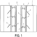
- a tire vulcanization mold 1 (hereinafter referred to as a mold 1) illustrated in FIGS. 1 to 3 is produced by the method for producing a tire vulcanization mold of the present invention.
- This mold 1 is a sector mold of a sectional type mold.
- Various groove molding portions 3 are provided so as to project from a tire molding surface 2.
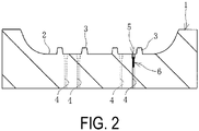
- the mold 1 is formed with an exhaust hole 4 for discharging unnecessary gas or the like generated during vulcanization of a green tire to the outside of the mold 1 to prevent a vulcanization failure, and one end of the exhaust hole 4 is open at a predetermined position Pm on the tire molding surface 2.
- a vent unit 5 is installed in the exhaust hole 4. That is, the vent unit 5 is installed at the predetermined position Pm on the tire molding surface 2.
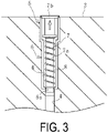
- the vent unit 5 has a case 6, and a valve body 7 and a spring 8 built in the case 6.
- the case 6 is a cylindrical body
- the valve body 7 has a shaft portion 7a and an enlarged-diameter portion 7b fixed to the tip of the shaft portion 7a.
- the valve body 7 is constantly urged to the opening on one side of the case 6 by the spring 8 externally inserted to the shaft portion 7a.
- the enlarged-diameter portion 7b slightly protrudes from the tire molding surface 2, and when the enlarged-diameter portion 7b is positioned opening the exhaust hole 4 in this way, the inside and the outside of the mold 1 communicate through the exhaust hole 4.
- valve body 7 is pressed by the green tire and retracts against the urging force of the spring 8.
- the enlarged-diameter portion 7b is positioned blocking the opening at one end of the exhaust hole 4, the communication between the inside and the outside of the mold 1 through the exhaust hole 4 is cut off.
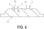
- a master mold 11 illustrated in FIG. 4 is produced.
- the master mold 11 has the same surface shape as the tire surface of the tire to be produced.
- a rear end 9b of a positioning member 9 is embedded at an attachment position Pc on the surface of the master mold 11, and a tip end 9a is installed so as to project from the surface.
- This attachment position Pc is a position corresponding to the predetermined position Pm of the mold 1 in which the vent unit 5 is installed.
- the positioning member 9 is, for example, a rod-shaped body, and can be produced using a metal such as stainless steel, iron, aluminum, or an aluminum alloy, various resins, or the like.
- a screw portion 9s is formed at least at the tip end 9a of the positioning member 9. The screw portion 9s may be formed over the entire length of the positioning member 9.
- a rubber mold 12 to which the surface of the master mold 11 is transferred is produced using the master mold 11. Therefore, as illustrated in FIG. 5 , the master mold 11 is arranged inside a mold frame 10A with the surface facing upward. A backup plate 12a is arranged above the mold frame 10A so that the surface of the backup plate 12a and the surface of the master mold 11 face each other. A rubber material R is poured and filled in the space between the surface of the backup plate 12a and the surface of the master mold 11 facing each other. When the filled rubber material R is solidified, the rubber mold 12 to which the surface of the master mold 11 is transferred is produced.
- the produced rubber mold 12 is separated from the master mold 11.
- a positioning hole 9H is formed in the surface of the produced rubber mold 12 by the tip end 9a.
- the positioning member 9 remains erected on the surface of the master mold 11.
- a plaster mold 13 to which the surface of the rubber mold 12 is transferred is produced. Therefore, the positioning member 9 removed from the master mold 11 is attached to the produced rubber mold 12. Specifically, the tip end 9a is embedded in the positioning hole 9H so that the rear end 9b protrudes from the surface of the rubber mold 12.
- the rubber mold 12 is placed in a mold frame 10B with the backup plate 12a in close contact with the back surface.
- Plaster P is poured onto the surface of the rubber mold 12.
- the plaster mold 13 to which the surface of the rubber mold 12 is transferred is produced.
- the produced plaster mold 13 is separated from the rubber mold 12.
- the rear end 9b of the positioning member 9 is embedded in the plaster mold 13, and the tip end 9a is in a state of protruding from the surface of the plaster mold 13.
- the mold 1 to which the surface of the plaster mold 13 is transferred is cast. Therefore, the case 6 is detachably fixed to the tip end 9a protruding from the surface of the plaster mold 13. That is, the screw portion 9s of the positioning member 9 and the screw portion 6s of the case 6 are engaged together so that the case 6 is detachably fixed to the positioning member 9.
- the plaster mold 13 is placed in a mold frame 10C with the surface facing upward. Then, for example, a molten metal M such as an aluminum material is poured onto the surface of the plaster mold 13. When the poured molten metal M is solidified, the mold 1 to which the surface of the plaster mold 13 is transferred is cast. After the molten metal M is solidified, the mold 1 is separated from the plaster mold 13.
- a molten metal M such as an aluminum material is poured onto the surface of the plaster mold 13.
- the case 6 is cast into the mold 1 and fixed.
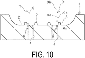
- the surface of the cast mold 1 becomes the tire molding surface 2, and the groove molding portion 3 is formed on the tire molding surface 2. Since the positioning member 9 is fixed to the case 6, the screw portions 6s and 9s are disengaged, and the positioning member 9 is removed from the case 6 as illustrated in FIG. 10 . After that, the spring 8 is inserted and attached together with the valve body 7 to the case 6 from which the positioning member 9 is removed.
- the exhaust hole 4 communicating with the inside of the case 6 is formed at an appropriate timing by drilling or the like from the back surface side of the mold 1.
- the tip end 9a of the positioning member 9 is installed at the attachment position Pc corresponding to the predetermined position Pm on the surface of the master mold 11 so as to protrude.
- the case 6 can be cast into the mold 1 and fixed at the predetermined position Pm with high accuracy using the positioning member 9.
- the valve body 7 is inserted into the case 6 and attached, so that the vent unit 5 can be installed at the predetermined position Pm on the tire molding surface 2 with high accuracy without requiring a large number of man-hours.
- the case 6 and the positioning member 9 have the screw portions 6s and 9s that engage with each other, the case 6 can be easily detachably fixed to the positioning member 9 in the process illustrated in FIG. 9 . Further, in the process illustrated in FIG. 10 , the positioning member 9 can be easily removed from the case 6.
- the process of attaching the valve body 7 and the spring 8 to the mold 1 can be performed manually, but can also be performed using an attachment mechanism 14A as illustrated in FIGS. 11 and 12 .
- the attachment mechanism 14A has a base 15 on which the cast mold 1 is placed, a robot arm 16, a head 17, and a control device 18.
- the robot arm 16 is configured by rotatably connecting a plurality of arm portions.
- a head 17 is attached to the tip end of the robot arm 16.
- a computer is used as the control device 18.
- the control device 18 has a storage unit 18a.
- the storage unit 18a stores the position data of the attachment position Pc in the master mold 11 and the shape data of the master mold 11.
- the movement of the robot arm 16 is controlled by the control device 18.
- As the head 17, a gripping head for gripping the valve body 7 to which the spring 8 is externally inserted is used as the head 17, a gripping head for gripping the valve body 7 to which the spring 8 is externally inserted is used.
- the base 15 is provided with a guide 15a for mounting the mold 1 by aligning the reference point and the direction of the mold 1 as desired.
- a guide 15a for mounting the mold 1 by aligning the reference point and the direction of the mold 1 as desired.
- an L-shaped protrusion that abuts on the side surface of a corner of the mold 1 is used as the guide 15a.
- the head 17 is moved based on the position data of the attachment position Pc stored in the storage unit 18a. Since the position data of the attachment position Pc indicates the position of the molding 1 where each case 6 is installed, the head 17 can be moved to the predetermined position Pm of the mold 1 where each case 6 is installed with high accuracy by controlling the movement of the head 17 via the robot arm 16 in this way. Then, the valve body 7 and the spring 8 are inserted into and attached to the case 6 by moving the head 17 close to the case 6 at the predetermined position Pm. As a result, the mold 1 in which the vent unit 5 illustrated in FIGS. 1 to 3 is installed at the predetermined position on the tire molding surface 2 is completed.
- contaminant X adheres to the vent unit 5. If the amount of deposited contaminant X increases, the venting by the vent unit 5 may not function normally and a vulcanization failure may occur. Therefore, a cleaning operation for removing the contaminant X adhering to the vent unit 5 in a timely manner is required.
- a maintenance mechanism 14B is used to perform maintenance work on the mold 1.
- this maintenance mechanism 14B only the head 17 of the attachment mechanism 14A described above is replaced.
- a cleaning head for removing the contaminant X adhering to the vent unit 5 is used as the head 17, as the head 17, a cleaning head for removing the contaminant X adhering to the vent unit 5 is used.
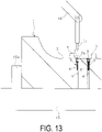
- the mold 1 When performing maintenance of the vent unit 5, as described above, the mold 1 is placed on the base 15 by aligning the coordinate axes of the position data of the attachment position Pc in the master mold 11 stored in the storage unit 18a so as to coincide with the coordinate axes of the mold 1 on the base 15. After that, as illustrated in FIG. 13 , the head 17 is moved based on the position data of the attachment position Pc stored in the storage unit 18a.
- the head 17 can be moved to the predetermined position Pm of the mold 1 in which each case 6 (vent unit 5) is installed with high accuracy by controlling the movement of the head 17 via the robot arm 16 in this way. Then, the head 17 performs a process of removing contaminant X from the vent unit 5 at the predetermined position Pm.
- the head 17 moved slightly above the vent unit 5 irradiates the vent unit 5 with a laser beam to remove the contaminant X adhering to the surface of the enlarged-diameter portion 7b and its surroundings, and the gap between the enlarged-diameter portion 7b and the tire molding surface 2.
- plasma is irradiated and compressed fluid is injected from the head 17 to remove the contaminant X.
- various known heads 17 for removing the contaminant X can be used.
- the head 17 can be quickly moved to the position of the vent unit 5 to perform the necessary maintenance work without performing processes such as detecting the position of the vent unit 5 each time the maintenance of the vent unit 5 is performed.
- valve body 7 and the spring 8 may be replaced.
- the spring 8 is pulled out from the case 6 together with the valve body 7 using a pull-out head that is caught or stuck in the enlarged-diameter portion 7b as the head 17. Then, using a gripping head as the head 17, a new valve body 7 and a spring 8 are inserted into the case 6 and replaced.
- the present invention is not limited to the sectional type mold, but can also be applied to a so-called two-split type mold. Further, the present invention can be applied not only to a mold for producing a pneumatic tire but also to a mold for producing various other types of tires.
Landscapes
- Engineering & Computer Science (AREA)
- Mechanical Engineering (AREA)
- Manufacturing & Machinery (AREA)
- Physics & Mathematics (AREA)
- Health & Medical Sciences (AREA)
- Oral & Maxillofacial Surgery (AREA)
- Thermal Sciences (AREA)
- Moulds For Moulding Plastics Or The Like (AREA)
- Heating, Cooling, Or Curing Plastics Or The Like In General (AREA)
Abstract
Description
- The present invention relates to a method for producing a tire vulcanization mold and a maintenance method therefor and particularly relates to a method for producing a tire vulcanization mold enabling accurate and efficient installation of a vent unit at a predetermined position on a tire molding surface of the tire vulcanization mold and a maintenance method enabling efficient maintenance of the vent unit.
- Installing a vent unit in an exhaust hole that opens to a tire molding surface in order to discharge unnecessary air and the like between a green tire and the tire molding surface to the outside of the mold is known (see, for example, Patent Document 1). When the vent unit is installed in a mold, the vent unit is formed at a predetermined position on the tire molding surface, and then the vent unit is pressed into the exhaust hole from the opening of the tire molding surface and fixed.
- An exhaust hole is formed by a drill or the like, but high-precision processing technology is required to accurately form the exhaust hole at a predetermined position on the tire molding surface according to target specifications. Therefore, it takes a considerable amount of time and effort to form a large number of exhaust holes. High accuracy is also required to position the vent unit in the exhaust hole. Furthermore, since the mold is made of a material with relatively low hardness such as aluminum, even if the exhaust hole is formed at a predetermined position, the vent unit will be displaced if the vent unit is not attached correctly. Therefore, there is room for improvement in accurately and efficiently installing the vent unit at a predetermined position on the tire molding surface.
- Since contaminants adhere to the vent unit due to repeated use of the mold, it is necessary to perform maintenance work such as removing the contaminants. For example, in order to remove a contaminant, a method of moving and controlling cleaning means to the position of a vent hole has been proposed (see Patent Document 2).
Patent Document 2 proposes using the CAD data of a tire molding surface as the position of an exhaust hole stored in advance (paragraph 0025), but it is not guaranteed that the vent hole has been accurately installed at the position of the vent hole in the CAD data. Further, it has been proposed that the position of the vent hole be calculated by the control means by comparing the shape information stored in advance of the molding surface including the position of the vent hole with the shape of the molding surface obtained by detection means. However, it is unclear how the position of the vent hole can be accurately determined as a result of the comparison. Furthermore, it takes a lot of time to detect the position of the vent hole by the detection means each time the vent hole is cleaned. Therefore, there is room for improvement in efficiently maintaining the vent unit. -
- Patent Document 1:
JP 2017-13312 A - Patent Document 2:
JP 2017-128013 A - An object of the present invention is to provide a method for producing a tire vulcanization mold enabling accurate and efficient installation of a vent unit at a predetermined position on the tire vulcanization mold and a maintenance method enabling efficient maintenance of the vent unit.
- In order to attain the object, a method for producing a tire vulcanization mold according to the present invention is a method for producing a tire vulcanization mold, including: producing a master mold having a same surface shape as a tire surface to be produced, subsequently producing a rubber mold to which a surface of the master mold is transferred, subsequently casting a plaster mold to which a surface of the rubber mold is transferred, subsequently casting a mold to which a surface of the plaster mold is transferred, and subsequently installing a vent unit at a predetermined position on a tire molding surface of the mold. A tip end of a positioning member at an attachment position corresponding to the predetermined position on the surface of the master mold is installed protruding, the rubber mold is produced using the master mold so that a positioning hole is formed in the rubber mold by the tip end, the tip end is embedded in the positioning hole with a rear end of the positioning member protruding from the surface of the rubber mold, the plaster mold is produced using the rubber mold so that the rear end is embedded in the plaster mold with the tip end protruding from the surface of the plaster mold, a case that constitutes a vent unit is detachably fixed to the tip end, the vulcanization mold is cast using the plaster mold so that the case is cast and fixed to the vulcanization mold, and a valve body that constitutes the vent unit is inserted and attached to the case removed from the positioning member so that the tire molding surface is installed in the vent unit.
- A maintenance method for a tire vulcanization mold according to the present invention is a maintenance method for a tire vulcanization mold for performing maintenance of the vent unit installed in the tire vulcanization mold produced according to the method for producing the tire vulcanization mold, the method including: storing position data of the attachment position in the master mold in a storage unit; and moving a head of a maintenance mechanism based on the position data of the attachment position stored in the storage unit when performing maintenance of the vent unit.
- According to the method for producing the tire vulcanization mold of the present invention, at the first stage of the process of producing the tire vulcanization mold, the tip end of the positioning member is installed at the attachment position corresponding to the predetermined position on the surface of the master mold so as to protrude. The case that constitutes the vent unit can be cast into the vulcanization mold and fixed at the predetermined position with high accuracy using the positioning member. Then, by inserting and attaching the valve body to the case from which the positioning member detachably fixed to the rear end has been removed, the vent unit can be attached to the predetermined portion on the tire molding surface with high accuracy without requiring a large number of man-hours.
- According to the maintenance method for the tire vulcanization mold of the present invention, the position data of the attachment position stored in the storage unit indicates the same position as the position data of the predetermined position on the tire vulcanization mold for fixing the vent unit. Therefore, by moving the head of the maintenance mechanism based on the position data of the attachment position stored in the storage unit when performing maintenance of the vent unit, the head can be positioned at the predetermined position at which the vent unit is installed. In this way, the head can be quickly moved to the position where the vent unit is installed and necessary maintenance work can be performed without performing processes such as detecting the position of the vent unit each time maintenance is performed.
-
-
FIG. 1 is an explanatory diagram illustrating a tire vulcanization mold produced by the present invention in a plan view. -
FIG. 2 is an explanatory diagram illustrating the mold ofFIG. 1 in a cross-sectional view. -
FIG. 3 is a partially enlarged view ofFIG. 2 . -
FIG. 4 is an explanatory diagram illustrating a master mold in a cross-sectional view. -
FIG. 5 is an explanatory diagram illustrating a process of producing a rubber mold in a cross-sectional view. -
FIG. 6 is an explanatory diagram illustrating a state in which the produced rubber mold is separated from the master mold in a cross-sectional view. -
FIG. 7 is an explanatory diagram illustrating a process of producing a plaster mold in a cross-sectional view. -
FIG. 8 is an explanatory diagram illustrating a state in which the produced plaster mold is separated from the rubber mold in a cross-sectional view. -
FIG. 9 is an explanatory diagram illustrating a process of casting a mold in a cross-sectional view. -
FIG. 10 is an explanatory diagram illustrating a cast mold in a cross-sectional view. -
FIG. 11 is an explanatory diagram illustrating a valve body attachment mechanism and a vent unit maintenance mechanism in a plan view. -
FIG. 12 is an explanatory diagram illustrating a process of attaching a valve body in a cross-sectional view. -
FIG. 13 is an explanatory diagram illustrating a process of cleaning a vent unit in a cross-sectional view. - Hereinafter, a method for producing a tire vulcanization mold and a maintenance method therefor of the present invention will be described based on the embodiment shown in the drawings.
- A tire vulcanization mold 1 (hereinafter referred to as a mold 1) illustrated in
FIGS. 1 to 3 is produced by the method for producing a tire vulcanization mold of the present invention. Thismold 1 is a sector mold of a sectional type mold. Variousgroove molding portions 3 are provided so as to project from atire molding surface 2. - The
mold 1 is formed with anexhaust hole 4 for discharging unnecessary gas or the like generated during vulcanization of a green tire to the outside of themold 1 to prevent a vulcanization failure, and one end of theexhaust hole 4 is open at a predetermined position Pm on thetire molding surface 2. Avent unit 5 is installed in theexhaust hole 4. That is, thevent unit 5 is installed at the predetermined position Pm on thetire molding surface 2. - As illustrated in
FIG. 3 , thevent unit 5 has acase 6, and avalve body 7 and a spring 8 built in thecase 6. Thecase 6 is a cylindrical body, and thevalve body 7 has a shaft portion 7a and an enlarged-diameter portion 7b fixed to the tip of the shaft portion 7a. Thevalve body 7 is constantly urged to the opening on one side of thecase 6 by the spring 8 externally inserted to the shaft portion 7a. The enlarged-diameter portion 7b slightly protrudes from thetire molding surface 2, and when the enlarged-diameter portion 7b is positioned opening theexhaust hole 4 in this way, the inside and the outside of themold 1 communicate through theexhaust hole 4. During vulcanization of the green tire, thevalve body 7 is pressed by the green tire and retracts against the urging force of the spring 8. When the enlarged-diameter portion 7b is positioned blocking the opening at one end of theexhaust hole 4, the communication between the inside and the outside of themold 1 through theexhaust hole 4 is cut off. - In order to produce this
mold 1, first, amaster mold 11 illustrated inFIG. 4 is produced. Themaster mold 11 has the same surface shape as the tire surface of the tire to be produced. Arear end 9b of apositioning member 9 is embedded at an attachment position Pc on the surface of themaster mold 11, and atip end 9a is installed so as to project from the surface. This attachment position Pc is a position corresponding to the predetermined position Pm of themold 1 in which thevent unit 5 is installed. - The positioning
member 9 is, for example, a rod-shaped body, and can be produced using a metal such as stainless steel, iron, aluminum, or an aluminum alloy, various resins, or the like. Ascrew portion 9s is formed at least at thetip end 9a of thepositioning member 9. Thescrew portion 9s may be formed over the entire length of thepositioning member 9. - Next, as illustrated in
FIGS. 5 to 6 , arubber mold 12 to which the surface of themaster mold 11 is transferred is produced using themaster mold 11. Therefore, as illustrated inFIG. 5 , themaster mold 11 is arranged inside a mold frame 10A with the surface facing upward. Abackup plate 12a is arranged above the mold frame 10A so that the surface of thebackup plate 12a and the surface of themaster mold 11 face each other. A rubber material R is poured and filled in the space between the surface of thebackup plate 12a and the surface of themaster mold 11 facing each other. When the filled rubber material R is solidified, therubber mold 12 to which the surface of themaster mold 11 is transferred is produced. - As illustrated in
FIG. 6 , the producedrubber mold 12 is separated from themaster mold 11. Apositioning hole 9H is formed in the surface of the producedrubber mold 12 by thetip end 9a. The positioningmember 9 remains erected on the surface of themaster mold 11. - Next, as illustrated in
FIGS. 7 to 8 , aplaster mold 13 to which the surface of therubber mold 12 is transferred is produced. Therefore, the positioningmember 9 removed from themaster mold 11 is attached to the producedrubber mold 12. Specifically, thetip end 9a is embedded in thepositioning hole 9H so that therear end 9b protrudes from the surface of therubber mold 12. - Then, the
rubber mold 12 is placed in amold frame 10B with thebackup plate 12a in close contact with the back surface. Plaster P is poured onto the surface of therubber mold 12. When the poured plaster P is solidified, theplaster mold 13 to which the surface of therubber mold 12 is transferred is produced. - As illustrated in
FIG. 8 , the producedplaster mold 13 is separated from therubber mold 12. Therear end 9b of thepositioning member 9 is embedded in theplaster mold 13, and thetip end 9a is in a state of protruding from the surface of theplaster mold 13. - Next, as illustrated in
FIGS. 9 to 10 , themold 1 to which the surface of theplaster mold 13 is transferred is cast. Therefore, thecase 6 is detachably fixed to thetip end 9a protruding from the surface of theplaster mold 13. That is, thescrew portion 9s of thepositioning member 9 and thescrew portion 6s of thecase 6 are engaged together so that thecase 6 is detachably fixed to thepositioning member 9. - The
plaster mold 13 is placed in amold frame 10C with the surface facing upward. Then, for example, a molten metal M such as an aluminum material is poured onto the surface of theplaster mold 13. When the poured molten metal M is solidified, themold 1 to which the surface of theplaster mold 13 is transferred is cast. After the molten metal M is solidified, themold 1 is separated from theplaster mold 13. - The
case 6 is cast into themold 1 and fixed. The surface of thecast mold 1 becomes thetire molding surface 2, and thegroove molding portion 3 is formed on thetire molding surface 2. Since thepositioning member 9 is fixed to thecase 6, thescrew portions positioning member 9 is removed from thecase 6 as illustrated inFIG. 10 . After that, the spring 8 is inserted and attached together with thevalve body 7 to thecase 6 from which thepositioning member 9 is removed. Theexhaust hole 4 communicating with the inside of thecase 6 is formed at an appropriate timing by drilling or the like from the back surface side of themold 1. - As described above, at the first stage of the process of producing the
mold 1, thetip end 9a of thepositioning member 9 is installed at the attachment position Pc corresponding to the predetermined position Pm on the surface of themaster mold 11 so as to protrude. Thecase 6 can be cast into themold 1 and fixed at the predetermined position Pm with high accuracy using thepositioning member 9. Then, after removing thepositioning member 9 from thecase 6 cast in themold 1, thevalve body 7 is inserted into thecase 6 and attached, so that thevent unit 5 can be installed at the predetermined position Pm on thetire molding surface 2 with high accuracy without requiring a large number of man-hours. - In the present embodiment, since the
case 6 and thepositioning member 9 have thescrew portions case 6 can be easily detachably fixed to thepositioning member 9 in the process illustrated inFIG. 9 . Further, in the process illustrated inFIG. 10 , the positioningmember 9 can be easily removed from thecase 6. - The process of attaching the
valve body 7 and the spring 8 to themold 1 can be performed manually, but can also be performed using anattachment mechanism 14A as illustrated inFIGS. 11 and12 . The attachment mechanism 14Ahas a base 15 on which thecast mold 1 is placed, arobot arm 16, ahead 17, and acontrol device 18. Therobot arm 16 is configured by rotatably connecting a plurality of arm portions. Ahead 17 is attached to the tip end of therobot arm 16. A computer is used as thecontrol device 18. Thecontrol device 18 has a storage unit 18a. The storage unit 18a stores the position data of the attachment position Pc in themaster mold 11 and the shape data of themaster mold 11. The movement of therobot arm 16 is controlled by thecontrol device 18. In the present embodiment, as thehead 17, a gripping head for gripping thevalve body 7 to which the spring 8 is externally inserted is used. - The
base 15 is provided with aguide 15a for mounting themold 1 by aligning the reference point and the direction of themold 1 as desired. For example, an L-shaped protrusion that abuts on the side surface of a corner of themold 1 is used as theguide 15a. By placing themold 1 on the base 15 in this way, the coordinate axes of the position data of the attachment position Pc in themaster mold 11 stored in the storage unit 18a coincide with the coordinate axes of themold 1 on thebase 15. - After that, as illustrated in
FIG. 12 , thehead 17 is moved based on the position data of the attachment position Pc stored in the storage unit 18a. Since the position data of the attachment position Pc indicates the position of themolding 1 where eachcase 6 is installed, thehead 17 can be moved to the predetermined position Pm of themold 1 where eachcase 6 is installed with high accuracy by controlling the movement of thehead 17 via therobot arm 16 in this way. Then, thevalve body 7 and the spring 8 are inserted into and attached to thecase 6 by moving thehead 17 close to thecase 6 at the predetermined position Pm. As a result, themold 1 in which thevent unit 5 illustrated inFIGS. 1 to 3 is installed at the predetermined position on thetire molding surface 2 is completed. - When the green tire is vulcanized by repeatedly using the
mold 1, contaminant X adheres to thevent unit 5. If the amount of deposited contaminant X increases, the venting by thevent unit 5 may not function normally and a vulcanization failure may occur. Therefore, a cleaning operation for removing the contaminant X adhering to thevent unit 5 in a timely manner is required. - Therefore, as illustrated in
FIGS. 11 and13 , amaintenance mechanism 14B is used to perform maintenance work on themold 1. In thismaintenance mechanism 14B, only thehead 17 of theattachment mechanism 14A described above is replaced. In the present embodiment, as thehead 17, a cleaning head for removing the contaminant X adhering to thevent unit 5 is used. - When performing maintenance of the
vent unit 5, as described above, themold 1 is placed on thebase 15 by aligning the coordinate axes of the position data of the attachment position Pc in themaster mold 11 stored in the storage unit 18a so as to coincide with the coordinate axes of themold 1 on thebase 15. After that, as illustrated inFIG. 13 , thehead 17 is moved based on the position data of the attachment position Pc stored in the storage unit 18a. - Since the position data of the attachment position Pc indicates the position of the
molding 1 where each case 6 (vent unit 5) is installed, thehead 17 can be moved to the predetermined position Pm of themold 1 in which each case 6 (vent unit 5) is installed with high accuracy by controlling the movement of thehead 17 via therobot arm 16 in this way. Then, thehead 17 performs a process of removing contaminant X from thevent unit 5 at the predetermined position Pm. - For example, the
head 17 moved slightly above thevent unit 5 irradiates thevent unit 5 with a laser beam to remove the contaminant X adhering to the surface of the enlarged-diameter portion 7b and its surroundings, and the gap between the enlarged-diameter portion 7b and thetire molding surface 2. Alternatively, plasma is irradiated and compressed fluid is injected from thehead 17 to remove the contaminant X. In addition, various knownheads 17 for removing the contaminant X can be used. Thehead 17 can be quickly moved to the position of thevent unit 5 to perform the necessary maintenance work without performing processes such as detecting the position of thevent unit 5 each time the maintenance of thevent unit 5 is performed. - As the maintenance work, in addition to removing the contaminant X, the
valve body 7 and the spring 8 may be replaced. When performing this work, for example, the spring 8 is pulled out from thecase 6 together with thevalve body 7 using a pull-out head that is caught or stuck in the enlarged-diameter portion 7b as thehead 17. Then, using a gripping head as thehead 17, anew valve body 7 and a spring 8 are inserted into thecase 6 and replaced. - The present invention is not limited to the sectional type mold, but can also be applied to a so-called two-split type mold. Further, the present invention can be applied not only to a mold for producing a pneumatic tire but also to a mold for producing various other types of tires.
-
- 1 Mold
- 2 Tire molding surface
- 3 Groove molding portion
- 4 Exhaust hole
- 5 Vent unit
- 6 Case
- 6s Screw portion
- 7 Valve body
- 7a Shaft portion
- 7b Enlarged-diameter portion
- 8 Spring
- 9 Positioning member
- 9a Tip end
- 9b Rear end
- 9s Screw portion
- 9H Positioning hole
- 10A, 10B, 10C Mold frame
- 11 Master mold
- 12 Rubber mold
- 12a Backup plate
- 13 Plaster mold
- 14A Attachment mechanism
- 14B Maintenance mechanism
- 15 Base
- 16 Arm
- 17 Head
- 18 Control device
- 18a Storage unit
- M Molten metal
- P Plaster
- R Rubber material
- X Contaminant
Claims (4)
- A method for producing a tire vulcanization mold, comprising:producing a master mold having a same surface shape as a tire surface to be produced;subsequently producing a rubber mold to which a surface of the master mold is transferred;subsequently casting a plaster mold to which a surface of the rubber mold is transferred;subsequently casting a mold to which a surface of the plaster mold is transferred; andsubsequently installing a vent unit at a predetermined position on a tire molding surface of the mold, whereina tip end of a positioning member at an attachment position corresponding to the predetermined position on the surface of the master mold is installed protruding;the rubber mold is produced using the master mold so that a positioning hole is formed in the rubber mold by the tip end;the tip end is embedded in the positioning hole with a rear end of the positioning member protruding from the surface of the rubber mold;the plaster mold is produced using the rubber mold so that the rear end is embedded in the plaster mold with the tip end protruding from the surface of the plaster mold;a case that constitutes a vent unit is detachably fixed to the tip end;the vulcanization mold is cast using the plaster mold so that the case is cast and fixed to the vulcanization mold; anda valve body that constitutes the vent unit is inserted and attached to the case removed from the positioning member so that the tire molding surface is installed in the vent unit.
- The method for producing the tire vulcanization mold according to claim 1, wherein
the case is detachably fixed to the rear end by engaging the case and the positioning member with each other. - A maintenance method for a tire vulcanization mold for performing maintenance of the vent unit installed in the tire vulcanization mold produced according to the method for producing the tire vulcanization mold according to claim 1 or 2, the method comprising:storing position data of the attachment position in the master mold in a storage unit; andmoving a head of a maintenance mechanism based on the position data of the attachment position stored in the storage unit when performing maintenance of the vent unit.
- The maintenance method for the tire vulcanization mold according to claim 3, wherein
a cleaning head that removes a contaminant adhering to the vent unit is used as the head.
Applications Claiming Priority (2)
| Application Number | Priority Date | Filing Date | Title |
|---|---|---|---|
| JP2020036369A JP7060030B2 (en) | 2020-03-04 | 2020-03-04 | Manufacturing method and maintenance method of tire vulcanization mold |
| PCT/JP2021/004068 WO2021176943A1 (en) | 2020-03-04 | 2021-02-04 | Method for producing mold for tire vulcanization and maintenance method |
Publications (3)
| Publication Number | Publication Date |
|---|---|
| EP4116055A1 true EP4116055A1 (en) | 2023-01-11 |
| EP4116055A4 EP4116055A4 (en) | 2024-04-17 |
| EP4116055B1 EP4116055B1 (en) | 2025-06-25 |
Family
ID=77614252
Family Applications (1)
| Application Number | Title | Priority Date | Filing Date |
|---|---|---|---|
| EP21764779.1A Active EP4116055B1 (en) | 2020-03-04 | 2021-02-04 | Method for producing mold for tire vulcanization and maintenance method |
Country Status (7)
| Country | Link |
|---|---|
| US (1) | US12157253B2 (en) |
| EP (1) | EP4116055B1 (en) |
| JP (1) | JP7060030B2 (en) |
| KR (1) | KR102473694B1 (en) |
| CN (1) | CN115103750A (en) |
| FI (1) | FI4116055T3 (en) |
| WO (1) | WO2021176943A1 (en) |
Families Citing this family (2)
| Publication number | Priority date | Publication date | Assignee | Title |
|---|---|---|---|---|
| CN117377909B (en) | 2021-08-26 | 2024-08-13 | 三井化学株式会社 | Protective film, protective film assembly, exposure original plate, exposure device and method for manufacturing protective film |
| FR3137867B1 (en) * | 2022-07-13 | 2024-06-14 | Michelin & Cie | System and Method for Acquisition and Determination of Valve Axes in Tire Vulcanization Molds |
Family Cites Families (18)
| Publication number | Priority date | Publication date | Assignee | Title |
|---|---|---|---|---|
| JPS62199242A (en) * | 1986-02-26 | 1987-09-02 | Hashiba Tekko Kk | Vent hold forming method for tire mold |
| JPH1034658A (en) * | 1996-07-26 | 1998-02-10 | Bridgestone Corp | Method for forming vent hole for mold for vulcanization of rubber molded article |
| JP2000102926A (en) * | 1998-09-28 | 2000-04-11 | Ngk Fine Mold Kk | Method for forming vent hole of tire mold |
| JP3589644B2 (en) * | 2000-12-07 | 2004-11-17 | 日本碍子株式会社 | Tire mold |
| JP2005131685A (en) * | 2003-10-31 | 2005-05-26 | Yokohama Rubber Co Ltd:The | Method for producing metallic mold for tire and sipe forming edge used for this method |
| JP2008247001A (en) * | 2007-03-30 | 2008-10-16 | Yokohama Rubber Co Ltd:The | Method for manufacturing vent hole of tire vulcanizing mold |
| JP2009255303A (en) * | 2008-04-11 | 2009-11-05 | Bridgestone Corp | Manufacturing method of mold |
| JP5092987B2 (en) * | 2008-08-21 | 2012-12-05 | 横浜ゴム株式会社 | Manufacturing method of tire vulcanization mold |
| WO2012141175A1 (en) * | 2011-04-14 | 2012-10-18 | 横浜ゴム株式会社 | Tire vulcanizing mold manufacturing method, and tire vulcanizing mold |
| JP2013193435A (en) * | 2012-03-22 | 2013-09-30 | Yokohama Rubber Co Ltd:The | Production method of mold for tire vulcanizing, and mold for tire vulcanizing |
| JP6088921B2 (en) * | 2013-07-02 | 2017-03-01 | 東洋ゴム工業株式会社 | Tire vulcanization mold and tire manufacturing method |
| JP6088927B2 (en) * | 2013-07-10 | 2017-03-01 | 東洋ゴム工業株式会社 | Tire vulcanization mold and tire manufacturing method |
| JP6059103B2 (en) | 2013-07-17 | 2017-01-11 | 東洋ゴム工業株式会社 | Tire vulcanization mold and tire manufacturing method |
| JP6501554B2 (en) * | 2015-02-18 | 2019-04-17 | 住友ゴム工業株式会社 | Vent hole cleaning jig, vent hole cleaning device and vent hole cleaning method |
| JP6527396B2 (en) * | 2015-06-16 | 2019-06-05 | 住友ゴム工業株式会社 | Vent plug for tire molding mold, and tire molding mold and tire manufacturing method using the same |
| JP6668623B2 (en) | 2015-06-30 | 2020-03-18 | 横浜ゴム株式会社 | Spring vent unit and tire vulcanization mold using the same |
| JP6583010B2 (en) | 2016-01-19 | 2019-10-02 | 住友ゴム工業株式会社 | Bent hole cleaning device and vent hole cleaning method. |
| US10442117B2 (en) * | 2017-04-17 | 2019-10-15 | Indian Institute Of Technology Bombay | Laser based tyre mold vent cleaning process and device |
-
2020
- 2020-03-04 JP JP2020036369A patent/JP7060030B2/en active Active
-
2021
- 2021-02-04 WO PCT/JP2021/004068 patent/WO2021176943A1/en not_active Ceased
- 2021-02-04 EP EP21764779.1A patent/EP4116055B1/en active Active
- 2021-02-04 KR KR1020227027199A patent/KR102473694B1/en active Active
- 2021-02-04 CN CN202180014746.6A patent/CN115103750A/en active Pending
- 2021-02-04 US US17/905,294 patent/US12157253B2/en active Active
- 2021-02-04 FI FIEP21764779.1T patent/FI4116055T3/en active
Also Published As
| Publication number | Publication date |
|---|---|
| JP7060030B2 (en) | 2022-04-26 |
| KR102473694B1 (en) | 2022-12-06 |
| FI4116055T3 (en) | 2025-09-25 |
| CN115103750A (en) | 2022-09-23 |
| KR20220116073A (en) | 2022-08-19 |
| WO2021176943A1 (en) | 2021-09-10 |
| EP4116055A4 (en) | 2024-04-17 |
| US12157253B2 (en) | 2024-12-03 |
| JP2021138015A (en) | 2021-09-16 |
| US20230127517A1 (en) | 2023-04-27 |
| EP4116055B1 (en) | 2025-06-25 |
Similar Documents
| Publication | Publication Date | Title |
|---|---|---|
| EP4116055B1 (en) | Method for producing mold for tire vulcanization and maintenance method | |
| EP3141367B1 (en) | Mold cleaning system | |
| EP2809482B1 (en) | Processing systems and method of operating the same | |
| EP3372370B1 (en) | Mold cleaning system | |
| EP3162524A1 (en) | Mold cleaning system | |
| EP1690625B1 (en) | Cap tip removing device of welding machine | |
| US9718159B2 (en) | Adaptive fastener access tool | |
| CN106198072A (en) | A kind of method of testing of the five axis robot control systems for injection machine | |
| CN111399441A (en) | Method, device and system for coordinating operation of robots performing work on parts | |
| US20080106017A1 (en) | Part holding device | |
| WO2002069062A3 (en) | A system and method for planning a tool path along a contoured surface | |
| CN104174989A (en) | Laser processing machine | |
| CN119609820A (en) | White car body weld polishing system and method | |
| CN207747067U (en) | A kind of robot hand replaces mechanism automatically | |
| EP3263293B1 (en) | Analysis of end effector operations by a robot | |
| US11358234B2 (en) | Nozzle distance confirming device and method of nozzle distance confirmation | |
| KR101759865B1 (en) | Method of coating sealant composition to inner surface of tire and tire manufactured by the same | |
| JP3346603B2 (en) | Lead frame side burr removal mechanism | |
| US20250153308A1 (en) | Polishing system and method of polishing a component | |
| CN120619814A (en) | A method for installing a compressor valve plate gasket | |
| US8161651B2 (en) | Method for manufacturing a door-trim assembly and its assembly line | |
| JP2010051883A (en) | Coating device and coating method | |
| CN118493523A (en) | Automatic rubber plug edge removing system and method | |
| JP2019005787A (en) | Expansion forming apparatus of can body workpiece | |
| CN121402603A (en) | A demolding control system for aluminum ingots with a visual recognition system |
Legal Events
| Date | Code | Title | Description |
|---|---|---|---|
| STAA | Information on the status of an ep patent application or granted ep patent |
Free format text: STATUS: THE INTERNATIONAL PUBLICATION HAS BEEN MADE |
|
| PUAI | Public reference made under article 153(3) epc to a published international application that has entered the european phase |
Free format text: ORIGINAL CODE: 0009012 |
|
| STAA | Information on the status of an ep patent application or granted ep patent |
Free format text: STATUS: REQUEST FOR EXAMINATION WAS MADE |
|
| 17P | Request for examination filed |
Effective date: 20220914 |
|
| AK | Designated contracting states |
Kind code of ref document: A1 Designated state(s): AL AT BE BG CH CY CZ DE DK EE ES FI FR GB GR HR HU IE IS IT LI LT LU LV MC MK MT NL NO PL PT RO RS SE SI SK SM TR |
|
| DAV | Request for validation of the european patent (deleted) | ||
| DAX | Request for extension of the european patent (deleted) | ||
| RAP3 | Party data changed (applicant data changed or rights of an application transferred) |
Owner name: THE YOKOHAMA RUBBER CO., LTD. |
|
| A4 | Supplementary search report drawn up and despatched |
Effective date: 20240314 |
|
| RIC1 | Information provided on ipc code assigned before grant |
Ipc: B29C 33/72 20060101ALI20240308BHEP Ipc: B29C 33/38 20060101ALI20240308BHEP Ipc: B29C 33/10 20060101ALI20240308BHEP Ipc: B29C 33/02 20060101AFI20240308BHEP |
|
| RAP3 | Party data changed (applicant data changed or rights of an application transferred) |
Owner name: THE YOKOHAMA RUBBER CO., LTD. |
|
| GRAP | Despatch of communication of intention to grant a patent |
Free format text: ORIGINAL CODE: EPIDOSNIGR1 |
|
| STAA | Information on the status of an ep patent application or granted ep patent |
Free format text: STATUS: GRANT OF PATENT IS INTENDED |
|
| INTG | Intention to grant announced |
Effective date: 20250217 |
|
| GRAS | Grant fee paid |
Free format text: ORIGINAL CODE: EPIDOSNIGR3 |
|
| GRAA | (expected) grant |
Free format text: ORIGINAL CODE: 0009210 |
|
| STAA | Information on the status of an ep patent application or granted ep patent |
Free format text: STATUS: THE PATENT HAS BEEN GRANTED |
|
| AK | Designated contracting states |
Kind code of ref document: B1 Designated state(s): AL AT BE BG CH CY CZ DE DK EE ES FI FR GB GR HR HU IE IS IT LI LT LU LV MC MK MT NL NO PL PT RO RS SE SI SK SM TR |
|
| REG | Reference to a national code |
Ref country code: GB Ref legal event code: FG4D |
|
| REG | Reference to a national code |
Ref country code: CH Ref legal event code: EP |
|
| REG | Reference to a national code |
Ref country code: CH Ref legal event code: EP |
|
| P01 | Opt-out of the competence of the unified patent court (upc) registered |
Free format text: CASE NUMBER: APP_26913/2025 Effective date: 20250605 |
|
| REG | Reference to a national code |
Ref country code: IE Ref legal event code: FG4D |
|
| REG | Reference to a national code |
Ref country code: DE Ref legal event code: R096 Ref document number: 602021032922 Country of ref document: DE |
|
| REG | Reference to a national code |
Ref country code: FI Ref legal event code: FGE |
|
| REG | Reference to a national code |
Ref country code: LT Ref legal event code: MG9D |
|
| PG25 | Lapsed in a contracting state [announced via postgrant information from national office to epo] |
Ref country code: GR Free format text: LAPSE BECAUSE OF FAILURE TO SUBMIT A TRANSLATION OF THE DESCRIPTION OR TO PAY THE FEE WITHIN THE PRESCRIBED TIME-LIMIT Effective date: 20250926 Ref country code: NO Free format text: LAPSE BECAUSE OF FAILURE TO SUBMIT A TRANSLATION OF THE DESCRIPTION OR TO PAY THE FEE WITHIN THE PRESCRIBED TIME-LIMIT Effective date: 20250925 |
|
| PG25 | Lapsed in a contracting state [announced via postgrant information from national office to epo] |
Ref country code: BG Free format text: LAPSE BECAUSE OF FAILURE TO SUBMIT A TRANSLATION OF THE DESCRIPTION OR TO PAY THE FEE WITHIN THE PRESCRIBED TIME-LIMIT Effective date: 20250625 |
|
| PG25 | Lapsed in a contracting state [announced via postgrant information from national office to epo] |
Ref country code: HR Free format text: LAPSE BECAUSE OF FAILURE TO SUBMIT A TRANSLATION OF THE DESCRIPTION OR TO PAY THE FEE WITHIN THE PRESCRIBED TIME-LIMIT Effective date: 20250625 |
|
| PG25 | Lapsed in a contracting state [announced via postgrant information from national office to epo] |
Ref country code: RS Free format text: LAPSE BECAUSE OF FAILURE TO SUBMIT A TRANSLATION OF THE DESCRIPTION OR TO PAY THE FEE WITHIN THE PRESCRIBED TIME-LIMIT Effective date: 20250925 |
|
| PG25 | Lapsed in a contracting state [announced via postgrant information from national office to epo] |
Ref country code: LV Free format text: LAPSE BECAUSE OF FAILURE TO SUBMIT A TRANSLATION OF THE DESCRIPTION OR TO PAY THE FEE WITHIN THE PRESCRIBED TIME-LIMIT Effective date: 20250625 |
|
| REG | Reference to a national code |
Ref country code: NL Ref legal event code: MP Effective date: 20250625 |
|
| PG25 | Lapsed in a contracting state [announced via postgrant information from national office to epo] |
Ref country code: NL Free format text: LAPSE BECAUSE OF FAILURE TO SUBMIT A TRANSLATION OF THE DESCRIPTION OR TO PAY THE FEE WITHIN THE PRESCRIBED TIME-LIMIT Effective date: 20250625 |
|
| PG25 | Lapsed in a contracting state [announced via postgrant information from national office to epo] |
Ref country code: PT Free format text: LAPSE BECAUSE OF FAILURE TO SUBMIT A TRANSLATION OF THE DESCRIPTION OR TO PAY THE FEE WITHIN THE PRESCRIBED TIME-LIMIT Effective date: 20251027 |
|
| REG | Reference to a national code |
Ref country code: AT Ref legal event code: MK05 Ref document number: 1806029 Country of ref document: AT Kind code of ref document: T Effective date: 20250625 |
|
| PG25 | Lapsed in a contracting state [announced via postgrant information from national office to epo] |
Ref country code: IS Free format text: LAPSE BECAUSE OF FAILURE TO SUBMIT A TRANSLATION OF THE DESCRIPTION OR TO PAY THE FEE WITHIN THE PRESCRIBED TIME-LIMIT Effective date: 20251025 |
|
| PG25 | Lapsed in a contracting state [announced via postgrant information from national office to epo] |
Ref country code: AT Free format text: LAPSE BECAUSE OF FAILURE TO SUBMIT A TRANSLATION OF THE DESCRIPTION OR TO PAY THE FEE WITHIN THE PRESCRIBED TIME-LIMIT Effective date: 20250625 Ref country code: SM Free format text: LAPSE BECAUSE OF FAILURE TO SUBMIT A TRANSLATION OF THE DESCRIPTION OR TO PAY THE FEE WITHIN THE PRESCRIBED TIME-LIMIT Effective date: 20250625 |
|
| PG25 | Lapsed in a contracting state [announced via postgrant information from national office to epo] |
Ref country code: PL Free format text: LAPSE BECAUSE OF FAILURE TO SUBMIT A TRANSLATION OF THE DESCRIPTION OR TO PAY THE FEE WITHIN THE PRESCRIBED TIME-LIMIT Effective date: 20250625 |
|
| PG25 | Lapsed in a contracting state [announced via postgrant information from national office to epo] |
Ref country code: EE Free format text: LAPSE BECAUSE OF FAILURE TO SUBMIT A TRANSLATION OF THE DESCRIPTION OR TO PAY THE FEE WITHIN THE PRESCRIBED TIME-LIMIT Effective date: 20250625 |
|
| PG25 | Lapsed in a contracting state [announced via postgrant information from national office to epo] |
Ref country code: SK Free format text: LAPSE BECAUSE OF FAILURE TO SUBMIT A TRANSLATION OF THE DESCRIPTION OR TO PAY THE FEE WITHIN THE PRESCRIBED TIME-LIMIT Effective date: 20250625 |
|
| PG25 | Lapsed in a contracting state [announced via postgrant information from national office to epo] |
Ref country code: ES Free format text: LAPSE BECAUSE OF FAILURE TO SUBMIT A TRANSLATION OF THE DESCRIPTION OR TO PAY THE FEE WITHIN THE PRESCRIBED TIME-LIMIT Effective date: 20250625 |
|
| PG25 | Lapsed in a contracting state [announced via postgrant information from national office to epo] |
Ref country code: DK Free format text: LAPSE BECAUSE OF FAILURE TO SUBMIT A TRANSLATION OF THE DESCRIPTION OR TO PAY THE FEE WITHIN THE PRESCRIBED TIME-LIMIT Effective date: 20250625 |
|
| PGFP | Annual fee paid to national office [announced via postgrant information from national office to epo] |
Ref country code: DE Payment date: 20251230 Year of fee payment: 6 |
|
| PG25 | Lapsed in a contracting state [announced via postgrant information from national office to epo] |
Ref country code: IT Free format text: LAPSE BECAUSE OF FAILURE TO SUBMIT A TRANSLATION OF THE DESCRIPTION OR TO PAY THE FEE WITHIN THE PRESCRIBED TIME-LIMIT Effective date: 20250625 |
|
| PGFP | Annual fee paid to national office [announced via postgrant information from national office to epo] |
Ref country code: FI Payment date: 20260213 Year of fee payment: 6 |
|
| PGFP | Annual fee paid to national office [announced via postgrant information from national office to epo] |
Ref country code: CZ Payment date: 20260119 Year of fee payment: 6 |
|
| PLBE | No opposition filed within time limit |
Free format text: ORIGINAL CODE: 0009261 |
|
| STAA | Information on the status of an ep patent application or granted ep patent |
Free format text: STATUS: NO OPPOSITION FILED WITHIN TIME LIMIT |
|
| REG | Reference to a national code |
Ref country code: CH Ref legal event code: L10 Free format text: ST27 STATUS EVENT CODE: U-0-0-L10-L00 (AS PROVIDED BY THE NATIONAL OFFICE) Effective date: 20260507 |