EP4115817B1 - Line-leading anchor screw - Google Patents
Line-leading anchor screw Download PDFInfo
- Publication number
- EP4115817B1 EP4115817B1 EP21798261.0A EP21798261A EP4115817B1 EP 4115817 B1 EP4115817 B1 EP 4115817B1 EP 21798261 A EP21798261 A EP 21798261A EP 4115817 B1 EP4115817 B1 EP 4115817B1
- Authority
- EP
- European Patent Office
- Prior art keywords
- anchor
- circular truncated
- abutment portion
- anchor head
- truncated cone
- Prior art date
- Legal status (The legal status is an assumption and is not a legal conclusion. Google has not performed a legal analysis and makes no representation as to the accuracy of the status listed.)
- Active
Links
Images


Classifications
-
- A—HUMAN NECESSITIES
- A61—MEDICAL OR VETERINARY SCIENCE; HYGIENE
- A61B—DIAGNOSIS; SURGERY; IDENTIFICATION
- A61B17/00—Surgical instruments, devices or methods
- A61B17/04—Surgical instruments, devices or methods for suturing wounds; Holders or packages for needles or suture materials
- A61B17/0401—Suture anchors, buttons or pledgets, i.e. means for attaching sutures to bone, cartilage or soft tissue; Instruments for applying or removing suture anchors
-
- A—HUMAN NECESSITIES
- A61—MEDICAL OR VETERINARY SCIENCE; HYGIENE
- A61B—DIAGNOSIS; SURGERY; IDENTIFICATION
- A61B17/00—Surgical instruments, devices or methods
- A61B17/04—Surgical instruments, devices or methods for suturing wounds; Holders or packages for needles or suture materials
- A61B17/0401—Suture anchors, buttons or pledgets, i.e. means for attaching sutures to bone, cartilage or soft tissue; Instruments for applying or removing suture anchors
- A61B2017/0403—Dowels
-
- A—HUMAN NECESSITIES
- A61—MEDICAL OR VETERINARY SCIENCE; HYGIENE
- A61B—DIAGNOSIS; SURGERY; IDENTIFICATION
- A61B17/00—Surgical instruments, devices or methods
- A61B17/04—Surgical instruments, devices or methods for suturing wounds; Holders or packages for needles or suture materials
- A61B17/0401—Suture anchors, buttons or pledgets, i.e. means for attaching sutures to bone, cartilage or soft tissue; Instruments for applying or removing suture anchors
- A61B2017/0412—Suture anchors, buttons or pledgets, i.e. means for attaching sutures to bone, cartilage or soft tissue; Instruments for applying or removing suture anchors having anchoring barbs or pins extending outwardly from suture anchor body
-
- A—HUMAN NECESSITIES
- A61—MEDICAL OR VETERINARY SCIENCE; HYGIENE
- A61B—DIAGNOSIS; SURGERY; IDENTIFICATION
- A61B17/00—Surgical instruments, devices or methods
- A61B17/04—Surgical instruments, devices or methods for suturing wounds; Holders or packages for needles or suture materials
- A61B17/0401—Suture anchors, buttons or pledgets, i.e. means for attaching sutures to bone, cartilage or soft tissue; Instruments for applying or removing suture anchors
- A61B2017/0414—Suture anchors, buttons or pledgets, i.e. means for attaching sutures to bone, cartilage or soft tissue; Instruments for applying or removing suture anchors having a suture-receiving opening, e.g. lateral opening
-
- A—HUMAN NECESSITIES
- A61—MEDICAL OR VETERINARY SCIENCE; HYGIENE
- A61B—DIAGNOSIS; SURGERY; IDENTIFICATION
- A61B17/00—Surgical instruments, devices or methods
- A61B17/04—Surgical instruments, devices or methods for suturing wounds; Holders or packages for needles or suture materials
- A61B17/0401—Suture anchors, buttons or pledgets, i.e. means for attaching sutures to bone, cartilage or soft tissue; Instruments for applying or removing suture anchors
- A61B2017/0445—Suture anchors, buttons or pledgets, i.e. means for attaching sutures to bone, cartilage or soft tissue; Instruments for applying or removing suture anchors cannulated, e.g. with a longitudinal through-hole for passage of an instrument
-
- A—HUMAN NECESSITIES
- A61—MEDICAL OR VETERINARY SCIENCE; HYGIENE
- A61B—DIAGNOSIS; SURGERY; IDENTIFICATION
- A61B17/00—Surgical instruments, devices or methods
- A61B17/04—Surgical instruments, devices or methods for suturing wounds; Holders or packages for needles or suture materials
- A61B17/0401—Suture anchors, buttons or pledgets, i.e. means for attaching sutures to bone, cartilage or soft tissue; Instruments for applying or removing suture anchors
- A61B2017/0446—Means for attaching and blocking the suture in the suture anchor
-
- A—HUMAN NECESSITIES
- A61—MEDICAL OR VETERINARY SCIENCE; HYGIENE
- A61B—DIAGNOSIS; SURGERY; IDENTIFICATION
- A61B17/00—Surgical instruments, devices or methods
- A61B17/04—Surgical instruments, devices or methods for suturing wounds; Holders or packages for needles or suture materials
- A61B17/0401—Suture anchors, buttons or pledgets, i.e. means for attaching sutures to bone, cartilage or soft tissue; Instruments for applying or removing suture anchors
- A61B2017/0446—Means for attaching and blocking the suture in the suture anchor
- A61B2017/0448—Additional elements on or within the anchor
-
- A—HUMAN NECESSITIES
- A61—MEDICAL OR VETERINARY SCIENCE; HYGIENE
- A61B—DIAGNOSIS; SURGERY; IDENTIFICATION
- A61B17/00—Surgical instruments, devices or methods
- A61B17/04—Surgical instruments, devices or methods for suturing wounds; Holders or packages for needles or suture materials
- A61B17/0401—Suture anchors, buttons or pledgets, i.e. means for attaching sutures to bone, cartilage or soft tissue; Instruments for applying or removing suture anchors
- A61B2017/0446—Means for attaching and blocking the suture in the suture anchor
- A61B2017/0458—Longitudinal through hole, e.g. suture blocked by a distal suture knot
Definitions
- the present application relates to the field of medical devices, and in particular to a suture anchor.
- the suture anchor is clinically used to reconnect a soft tissue and a bone through a suture thread, the anchor is buried in the bone for fixation, and the suture thread carried on the anchor cooperates with a suture needle to fix the soft tissue.
- the existing suture anchor includes an anchor head and an anchor body, wherein the anchor head has a threading hole, and the suture thread passes through the threading hole.
- the anchor body is a multi-layer cone-tower structure, so when the anchor head is buried in a groove opened on the bone and then the anchor body is inserted into the groove, an outer ring of the anchor body will abut against the inner wall of the groove for fixation, so that the anchor head cannot escape from the groove.
- the patent application CN 112 494 089 A discloses a knotting-free anchor and an anchor implantation instrument.
- the knotting-free anchor comprises an anchor body, an axial center hole axially penetrating through the anchor body is formed in the anchor body, and the anchor body comprises a threaded connection section. At least one notch is formed in the edge of the external thread of the threaded connection section.
- the patent application CN 107 582 118 A discloses an anchor with a suture and particularly a semi-threaded anchor with a suture.
- the semi-threaded anchor comprises an anchor body, wherein a threaded portion is arranged on the outer side face of the anchor body, and a threading hole is formed in the anchor body in a penetrating mode.
- a plurality of cutting portions are arranged on the threaded portion in a staggered mode, each of the cutting portions comprises a first cutting face and a second cutting face, and an included angle is formed by the first cutting face and the second cutting face.
- the patent application CN 107 569 264 A discloses a wiring rivet, and especially a knot-free sewing rivet.
- the knot-free sewing rivet comprises a rivet main body; the rivet main body comprises several groups of coaxial member parts overlapped in order; every group of member part comprises a first member and a second member which are overlapped coaxially, the first member is placed at the upper part of the second member; the first member and the second member are in the shape of round platform.
- the rivet main body further comprises a taper part, and the taper part is arranged at the bottom part of the lowermost member part. The area of first member, the second member and the taper part is gradually reduced from the upper part of the rivet main body to the lower part of the rivet main body.
- the patent application CN 110 840 500 A discloses an anchor with a thread.
- An inner core empty cavity is formed in the anchor body, at the same time, a thread through hole is further formed, and the thread through hole is communicated with the inner core empty cavity; furthermore, the anchor further comprises an inner core, which is matched with the inner core empty cavity.
- the patent application CN 207 886 227 U discloses a medical anchor nail, wherein an axial tooth's socket has been defined on the thread of the first nail post and the second nail post, and is equipped with the reverse pawl of thread on the tooth's socket.
- the sclerotin can sink into in the tooth's socket and wrap up the pawl simultaneously.
- an appurtenance is adopted to carry the bolt piece at the top of the second nail post and so can rotate the second nail post.
- the first nail post is fixed at the tail of second nail post and can slowly get into the sclerotin with its thread.
- the through-hole and wire hole on this bolt piece can be configured to be passed through by the wire.
- the patent application US 2007/150003A1 discloses an insert-molded suture anchor with a biodegradable polymer body in which a loop of suture is totally contained within the polymer.
- the suture anchor body features a drive end that is shaped to be received into a recess in the end of a hand driver.
- Anchoring ribs are formed along the remaining length of the anchor.
- the loop of suture which includes and eyelet for attaching a suture strand is totally embedded within the anchor body during the insert-molding fabrication process.
- the anchor is produced by placing the suture in an injection mold, and injecting biodegradable polymer into the mold.
- the suture thread needs to pass through the groove from the position between the anchor body and the inner wall of the groove opened on the bone for the doctor to operate.
- the suture thread is easily damaged and broken when it receives a squeezing between the edge position of the cone-tower structure of the anchor body and the inner wall of the groove.
- the claimed invention provides a suture anchor as defined in claim 1.
- Optional features are recited in the dependent claims.
- the present application provides a suture anchor.
- the suture anchor according to the present application adopts the following technical solutions.
- a suture anchor includes an anchor head and an anchor body, wherein a threading hole is formed on the anchor head, the anchor body includes a laterally pressing part (also referred to as laterally pressing portion, side pressing part or side pressing portion in the following) integrally formed by a plurality of layers of circular truncated cones, and at least two opposite longitudinal cuts are formed on each circular truncated cone of the laterally pressing part; from a direction close to the anchor head to a direction away from the anchor head, positions of the longitudinal cuts on adjacent circular truncated cones are deviated toward a same side.
- a laterally pressing part also referred to as laterally pressing portion, side pressing part or side pressing portion in the following
- the anchor head and the anchor body are connected to an anchor operating handle, then the suture thread is passed through the threading hole, and the anchor head and the anchor body are pushed into the groove opened on the bone through the anchor operating handle.
- the outer ring of the abutment portion and the inner wall of the bone groove abut and fit for fixation.
- the suture thread passes through the bone groove from the position where the longitudinal cuts are formed on the anchor body. Since the longitudinal cuts of each layer are not arranged in a whole row and they are arranged in a deviation manner, when the suture thread is stretched and straightened, the suture thread will pass through the center position of parts of the longitudinal cuts and also pass through the edge position of parts of the longitudinal cuts. The position of the edge parts of the longitudinal cuts will cooperate with the inner wall of the bone groove to squeeze and fix the suture thread without causing the suture thread to break.
- the positions of the longitudinal cuts on adjacent circular truncated cones are deviated by a same angle in a clockwise or counterclockwise direction from a top view, and a deviation angle of the longitudinal cuts on the adjacent circular truncated cones is from 0 to 45 degrees.
- the positions of the longitudinal cuts on the adjacent circular truncated cones are set at the same deviation angle, so that the staggered positions formed by the longitudinal cuts between adjacent circular truncated cones just match and fix the suture thread.
- At least four longitudinal cuts are formed uniformly on each circular truncated cone of the side pressing portion along a circumferential circle.
- At least four longitudinal cuts are provided in a circle around the circular truncated cone so that the suture thread can pass through the bone groove at the position of the longitudinal cuts when the suture thread is stretched in each direction, without the need for deliberately adjusting the position of the suture thread during the surgery.
- the anchor body further includes an abutment portion located at an end of the side pressing portion close to the anchor head, the abutment portion has a circular truncated cone shape, and a taper of the abutment portion is greater than that of the circular truncated cone of the side pressing portion.
- the abutment portion of the anchor body is set to be a circular truncated cone structure with a taper greater than that of the circular truncated cone of the side pressing portion, and the anchor head is abutted and fixed by the abutment portion.
- a first arc surface that is concave from both sides to the middle is formed on bottom of the anchor head, and a second arc surface that protrudes from both sides to the middle is formed on top of the abutment portion, and the second arc surface and the first arc surface fit with each other when being abutted tightly.
- the first arc surface formed on the bottom of the anchor head and the second arc surface of the abutment portion cooperate, so that when the first arc surface and the second arc surface abut, the mating angle of the anchor head and the anchor body is also determined.
- the number of longitudinal cuts on each layer circular truncated cone of the side pressing portion is two; when the first arc surface abuts on the second arc surface, a side edge of a longitudinal cut on the circular truncated cone nearest to the anchor head directly faces the threading hole, and the other side edge of the longitudinal cut on the circular truncated cone furthest from the anchor head directly faces the threading hole.
- a plurality of oblique cuts are uniformly formed on a circumference of the abutment portion in a circumferential direction, and a cutting depth of the oblique cut at a position near a lower end of the abutment portion is greater than a cutting depth at a position near a top end of the abutment portion.
- the top of the anchor head is a convex arc shape.
- the top of the anchor head is set to be a circular arc shape, so that the anchor head will not be embedded into the bottom surface of the bone groove after being squeezed.
- a screw hole is formed on the bottom of the anchor head.
- the screw hole is provided on the bottom of the anchor head to cooperate with the anchor operating handle.
- the anchor operating handle can be rotated. After the anchor operating handle is separated from the anchor head, the anchor operating handle is pulled out.
- the present application includes at least one of the following beneficial technical effects.
- the present application embodiment discloses a suture anchor.
- a suture anchor includes an anchor head 1 and an anchor body 2, the top of the anchor head 1 is a convex arc shape, a threading hole 3 is formed on the front face of the anchor head 1, and a screw hole 4 is formed on the bottom of the anchor head 1.
- the anchor body 2 includes a side pressing portion 5 integrally formed by ten layers of circular truncated cones, and an abutment portion 6 integrally formed on the top of the side pressing portion 5.
- a through hole 7 for passing through an anchor operating handle is formed in the middle of the anchor body 2.
- the abutment portion 6 has a circular truncated cone shape, and the taper of the abutment portion 6 is greater than that of the side pressing portion 5.
- oblique cuts 8 are uniformly formed on a circumference of the abutment portion 6 in a circumferential direction.
- Each oblique cut 8 has a shallow cutting depth at a position close to the top end of the abutment portion 6, and a deep cutting depth at a position close to the lower end of the abutment portion 6.
- Eight longitudinal cuts 9 are uniformly formed on a circumference of each circular truncated cone of the side pressing portion 5 in the circumferential direction, and each longitudinal cut 9 cuts the circular truncated cone of the abutment portion 6 in the vertical direction.
- the positions of the longitudinal cuts 9 on the adjacent circular truncated cones from top to bottom have a small angular deviation toward the same direction.
- the anchor head 1 and the anchor body 2 are connected to the anchor operating handle, the suture thread is passed through the threading hole 3, and the anchor head 1 and the anchor body 2 are pushed into a groove opened on the bone with the anchor operating handle.
- the outer ring of the abutment portion 6 abuts on and fits to the inner wall of the bone groove for fixation.
- the anchor head 1 abuts on the anchor body 2.
- the suture thread passes through the bone groove from a position where the longitudinal cuts 9 are formed on the anchor body 2. Since the positions of the longitudinal cuts 9 on each layer are deviated relative to each other, when the suture thread is stretched and straightened outwards, the suture thread can pass through a part with a larger gap between the abutment portion 6 and the bone groove, and can also pass through a part with a smaller gap therebetween, so that the suture thread is firmly fixed and cannot be cut off by the edge of the circular truncated cone.
- a suture anchor includes an anchor head 1 and an anchor body 2, the top of the anchor head 1 is a convex arc shape, and a threading hole 3 is formed on the front face of the anchor head 1.
- the anchor body 2 includes a side pressing portion 5 integrally formed by ten layers of circular truncated cones, and an abutment portion 6 integrally formed on the top of the side pressing portion 5.
- a through hole 7 for passing through an anchor operating handle is formed in the middle of the anchor body 2.
- the abutment portion 6 has a circular truncated cone shape, and the taper of the abutment portion 6 is greater than that of the side pressing portion 5.
- a second arc surface 11, which protrudes from both sides to the middle, is formed on the top of the abutment portion 6, and the second arc surface 11 can abut on and fit with the first arc surface 10.
- oblique cuts 8 are formed on the front and back sides of the abutment portion 6.
- the oblique cut 8 has a shallow cutting depth at a position close to the top end of the abutment portion 6, and has a deep cutting depth at a position close to the lower end of the abutment portion 6.
- Longitudinal cuts 9 are formed on both the front and back sides of each circular truncated cone of the side pressing portion 5, and each longitudinal cut 9 cuts the circular truncated cone of the abutment portion 6 in the vertical direction.
- the positions of the longitudinal cuts 9 on the adjacent circular truncated cones from top to bottom have a small angular deviation toward the same direction.
- the anchor head 1 and the anchor body 2 are connected to the anchor operating handle, the suture thread is passed through the threading hole 3, and the anchor head 1 and the anchor body 2 are pushed into a groove opened on the bone with the anchor operating handle.
- the outer ring of the abutment portion 6 abuts on and fits to the inner wall of a groove opened on the bone for fixation.
- a right edge of a longitudinal cut 9 on the circular truncated cone closest to the anchor head 1 directly faces the threading hole 3
- a left edge of a longitudinal cut 9 on the circular truncated cone furthest from the anchor head 1 directly faces the threading hole 3.
- the suture thread when the suture thread is stretched and straightened outwards, the suture thread can pass through a part with a larger gap between the abutment portion 6 and the bone groove, and can also pass through a part with a smaller gap therebetween, so that the suture thread is firmly fixed and cannot be cut off by the edge of the circular truncated cone.
- the anchor body 2 includes a side pressing portion 5 integrally formed by a plurality of layers of circular truncated cones, and an abutment portion 6 integrally formed on the top of the side pressing portion 5.
- the abutment portion 6 has a circular truncated cone shape, and the taper of the abutment portion 6 is greater than or equal to the taper of the circular truncated cone of the side pressing portion 5.
- At least two oblique cuts 8 are uniformly formed on a circumference of the abutment portion 6 in the circumferential direction.
- Each oblique cut 8 has a shallow cutting depth at a position close to the top end of the abutment portion 6, and has a deep cutting depth at a position close to the lower end of the abutment portion 6.
- Longitudinal cuts 9, which are equal in number to the oblique cuts 8, are uniformly formed on a circumference of each circular truncated cone of the side pressing portion 5 in the circumferential direction.
- Each longitudinal cut 9 cuts the circular truncated cone of the abutment portion 6 in the vertical direction. From the top view, the positions of the longitudinal cuts 9 on the adjacent circular truncated cones from top to bottom is deviated by an angle of 5 degrees in the clockwise direction. From the top view, the oblique cuts 8 have an angle of 5 degrees in the counterclockwise direction relative to the longitudinal cuts 9 on the adjacent side pressing portion 5.
- the anchor body 2 includes a side pressing portion 5 integrally formed by a plurality of layers of circular truncated cones, and an abutment portion 6 integrally formed on the top of the side pressing portion 5.
- the abutment portion 6 has a circular truncated cone shape, and the taper of the abutment portion 6 is greater than or equal to the taper of the circular truncated cone of the side pressing portion 5.
- At least two oblique cuts 8 are uniformly formed on a circumference of the abutment portion 6 in the circumferential direction.
- Each oblique cut 8 has a shallow cutting depth at a position close to the top end of the abutment portion 6, and has a deep cutting depth at a position close to the lower end of the abutment portion 6.
- Longitudinal cuts 9, which are equal in number to the oblique cuts 8, are uniformly formed on a circumference of each circular truncated cone of the side pressing portion 5 in the circumferential direction.
- Each longitudinal cut 9 cuts the circular truncated cone of the abutment portion 6 in the vertical direction. From the top view, the positions of the longitudinal cuts 9 on the adjacent circular truncated cones from top to bottom is deviated by an angle of 10 degrees in the clockwise direction. From the top view, the oblique cuts 8 have an angle of 10 degrees in the counterclockwise direction relative to the longitudinal cuts 9 on the adjacent side pressing portion 5.
- the anchor body 2 includes a side pressing portion 5 integrally formed by a plurality of layers of circular truncated cones, and an abutment portion 6 integrally formed on the top of the side pressing portion 5.
- the abutment portion 6 has a circular truncated cone shape, and the taper of the abutment portion 6 is greater than or equal to the taper of the circular truncated cone of the side pressing portion 5.
- At least two oblique cuts 8 are uniformly formed on a circumference of the abutment portion 6 in the circumferential direction.
- Each oblique cut 8 has a shallow cutting depth at a position close to the top end of the abutment portion 6, and has a deep cutting depth at a position close to the lower end of the abutment portion 6.
- Longitudinal cuts 9, which are equal in number to the oblique cuts 8, are uniformly formed on a circumference of each circular truncated cone of the side pressing portion 5 in the circumferential direction.
- Each longitudinal cut 9 cuts the circular truncated cone of the abutment portion 6 in the vertical direction. From the top view, the positions of the longitudinal cuts 9 on the adjacent circular truncated cones from top to bottom is deviated by an angle of 15 degrees in the clockwise direction. From the top view, the oblique cuts 8 have an angle of 15 degrees in the counterclockwise direction relative to the longitudinal cuts 9 on the adjacent side pressing portion 5.
- the anchor body 2 includes a side pressing portion 5 integrally formed by a plurality of layers of circular truncated cones, and an abutment portion 6 integrally formed on the top of the side pressing portion 5.
- the abutment portion 6 has a circular truncated cone shape, and the taper of the abutment portion 6 is greater than or equal to the taper of the circular truncated cone of the side pressing portion 5.
- At least two oblique cuts 8 are uniformly formed on a circumference of the abutment portion 6 in the circumferential direction.
- Each oblique cut 8 has a shallow cutting depth at a position close to the top end of the abutment portion 6, and has a deep cutting depth at a position close to the lower end of the abutment portion 6.
- Longitudinal cuts 9, which are equal in number to the oblique cuts 8, are uniformly formed on a circumference of each circular truncated cone of the side pressing portion 5 in the circumferential direction.
- Each longitudinal cut 9 cuts the circular truncated cone of the abutment portion 6 in the vertical direction. From the top view, the positions of the longitudinal cuts 9 on the adjacent circular truncated cones from top to bottom is deviated by an angle of 45 degrees in the counterclockwise direction. From the top view, the oblique cuts 8 have an angle of 45 degrees in the clockwise direction relative to the longitudinal cuts 9 on the adjacent side pressing portion 5.
Landscapes
- Health & Medical Sciences (AREA)
- Surgery (AREA)
- Life Sciences & Earth Sciences (AREA)
- Biomedical Technology (AREA)
- Nuclear Medicine, Radiotherapy & Molecular Imaging (AREA)
- Engineering & Computer Science (AREA)
- Rheumatology (AREA)
- Heart & Thoracic Surgery (AREA)
- Medical Informatics (AREA)
- Molecular Biology (AREA)
- Animal Behavior & Ethology (AREA)
- General Health & Medical Sciences (AREA)
- Public Health (AREA)
- Veterinary Medicine (AREA)
- Surgical Instruments (AREA)
Description
- The present application relates to the field of medical devices, and in particular to a suture anchor.
- The suture anchor is clinically used to reconnect a soft tissue and a bone through a suture thread, the anchor is buried in the bone for fixation, and the suture thread carried on the anchor cooperates with a suture needle to fix the soft tissue. The existing suture anchor includes an anchor head and an anchor body, wherein the anchor head has a threading hole, and the suture thread passes through the threading hole. The anchor body is a multi-layer cone-tower structure, so when the anchor head is buried in a groove opened on the bone and then the anchor body is inserted into the groove, an outer ring of the anchor body will abut against the inner wall of the groove for fixation, so that the anchor head cannot escape from the groove.
- In the prior art, there are known some methods or devices as described in their respective documents.
- The patent application
CN 112 494 089 A discloses a knotting-free anchor and an anchor implantation instrument. The knotting-free anchor comprises an anchor body, an axial center hole axially penetrating through the anchor body is formed in the anchor body, and the anchor body comprises a threaded connection section. At least one notch is formed in the edge of the external thread of the threaded connection section. - The patent application
CN 107 582 118 A discloses an anchor with a suture and particularly a semi-threaded anchor with a suture. The semi-threaded anchor comprises an anchor body, wherein a threaded portion is arranged on the outer side face of the anchor body, and a threading hole is formed in the anchor body in a penetrating mode. A plurality of cutting portions are arranged on the threaded portion in a staggered mode, each of the cutting portions comprises a first cutting face and a second cutting face, and an included angle is formed by the first cutting face and the second cutting face. - The patent application
CN 107 569 264 A discloses a wiring rivet, and especially a knot-free sewing rivet. The knot-free sewing rivet comprises a rivet main body; the rivet main body comprises several groups of coaxial member parts overlapped in order; every group of member part comprises a first member and a second member which are overlapped coaxially, the first member is placed at the upper part of the second member; the first member and the second member are in the shape of round platform. The rivet main body further comprises a taper part, and the taper part is arranged at the bottom part of the lowermost member part. The area of first member, the second member and the taper part is gradually reduced from the upper part of the rivet main body to the lower part of the rivet main body. - The patent application
CN 110 840 500 A discloses an anchor with a thread. An inner core empty cavity is formed in the anchor body, at the same time, a thread through hole is further formed, and the thread through hole is communicated with the inner core empty cavity; furthermore, the anchor further comprises an inner core, which is matched with the inner core empty cavity. When a fixing suture passes through the thread passing hole, the inner core penetrates into the inner core empty cavity to compress the fixing suture, after the fixing suture is compressed, the fixing suture is fixed at the position of the thread passing hole. - The patent application
CN 207 886 227 U discloses a medical anchor nail, wherein an axial tooth's socket has been defined on the thread of the first nail post and the second nail post, and is equipped with the reverse pawl of thread on the tooth's socket. After this anchor nail was put into the sclerotin, the sclerotin can sink into in the tooth's socket and wrap up the pawl simultaneously. During being put into sclerotin, an appurtenance is adopted to carry the bolt piece at the top of the second nail post and so can rotate the second nail post. The first nail post is fixed at the tail of second nail post and can slowly get into the sclerotin with its thread. The through-hole and wire hole on this bolt piece can be configured to be passed through by the wire. - The patent application
US 2007/150003A1 discloses an insert-molded suture anchor with a biodegradable polymer body in which a loop of suture is totally contained within the polymer. The suture anchor body features a drive end that is shaped to be received into a recess in the end of a hand driver. Anchoring ribs are formed along the remaining length of the anchor. The loop of suture which includes and eyelet for attaching a suture strand is totally embedded within the anchor body during the insert-molding fabrication process. The anchor is produced by placing the suture in an injection mold, and injecting biodegradable polymer into the mold. - For the above-mentioned related technologies, the suture thread needs to pass through the groove from the position between the anchor body and the inner wall of the groove opened on the bone for the doctor to operate. The suture thread is easily damaged and broken when it receives a squeezing between the edge position of the cone-tower structure of the anchor body and the inner wall of the groove.
- The claimed invention provides a suture anchor as defined in
claim 1. Optional features are recited in the dependent claims. - In order to facilitate the fixing of the suture thread without breaking the suture thread due to squeezing, the present application provides a suture anchor.
- The suture anchor according to the present application adopts the following technical solutions.
- A suture anchor includes an anchor head and an anchor body, wherein a threading hole is formed on the anchor head, the anchor body includes a laterally pressing part (also referred to as laterally pressing portion, side pressing part or side pressing portion in the following) integrally formed by a plurality of layers of circular truncated cones, and at least two opposite longitudinal cuts are formed on each circular truncated cone of the laterally pressing part; from a direction close to the anchor head to a direction away from the anchor head, positions of the longitudinal cuts on adjacent circular truncated cones are deviated toward a same side.
- By adopting the above technical solution, the anchor head and the anchor body are connected to an anchor operating handle, then the suture thread is passed through the threading hole, and the anchor head and the anchor body are pushed into the groove opened on the bone through the anchor operating handle. The outer ring of the abutment portion and the inner wall of the bone groove abut and fit for fixation. The suture thread passes through the bone groove from the position where the longitudinal cuts are formed on the anchor body. Since the longitudinal cuts of each layer are not arranged in a whole row and they are arranged in a deviation manner, when the suture thread is stretched and straightened, the suture thread will pass through the center position of parts of the longitudinal cuts and also pass through the edge position of parts of the longitudinal cuts. The position of the edge parts of the longitudinal cuts will cooperate with the inner wall of the bone groove to squeeze and fix the suture thread without causing the suture thread to break.
- Preferably, the positions of the longitudinal cuts on adjacent circular truncated cones are deviated by a same angle in a clockwise or counterclockwise direction from a top view, and a deviation angle of the longitudinal cuts on the adjacent circular truncated cones is from 0 to 45 degrees.
- By adopting the above technical solution, the positions of the longitudinal cuts on the adjacent circular truncated cones are set at the same deviation angle, so that the staggered positions formed by the longitudinal cuts between adjacent circular truncated cones just match and fix the suture thread. The thicker the suture thread used, the larger the deviation angle.
- Preferably, at least four longitudinal cuts are formed uniformly on each circular truncated cone of the side pressing portion along a circumferential circle.
- By adopting the above technical solution, at least four longitudinal cuts are provided in a circle around the circular truncated cone so that the suture thread can pass through the bone groove at the position of the longitudinal cuts when the suture thread is stretched in each direction, without the need for deliberately adjusting the position of the suture thread during the surgery.
- Preferably, the anchor body further includes an abutment portion located at an end of the side pressing portion close to the anchor head, the abutment portion has a circular truncated cone shape, and a taper of the abutment portion is greater than that of the circular truncated cone of the side pressing portion.
- By adopting the above technical solution, the abutment portion of the anchor body is set to be a circular truncated cone structure with a taper greater than that of the circular truncated cone of the side pressing portion, and the anchor head is abutted and fixed by the abutment portion.
- Preferably, a first arc surface that is concave from both sides to the middle is formed on bottom of the anchor head, and a second arc surface that protrudes from both sides to the middle is formed on top of the abutment portion, and the second arc surface and the first arc surface fit with each other when being abutted tightly.
- By adopting the above technical solution, the first arc surface formed on the bottom of the anchor head and the second arc surface of the abutment portion cooperate, so that when the first arc surface and the second arc surface abut, the mating angle of the anchor head and the anchor body is also determined.
- Preferably, the number of longitudinal cuts on each layer circular truncated cone of the side pressing portion is two; when the first arc surface abuts on the second arc surface, a side edge of a longitudinal cut on the circular truncated cone nearest to the anchor head directly faces the threading hole, and the other side edge of the longitudinal cut on the circular truncated cone furthest from the anchor head directly faces the threading hole.
- By adopting the above technical solution, when the matching angle of the anchor head and the anchor body is determined, only two longitudinal cuts are provided on each layer circular truncated cone to match the suture thread for passing out. Since the complete structure of the side pressing portion is retained as much as possible, the structural strength of the side pressing portion is better and is not easily damaged.
- Preferably, a plurality of oblique cuts are uniformly formed on a circumference of the abutment portion in a circumferential direction, and a cutting depth of the oblique cut at a position near a lower end of the abutment portion is greater than a cutting depth at a position near a top end of the abutment portion.
- By adopting the above technical solution, oblique cuts are provided on the abutment portion to avoid the suture thread.
- Preferably, the top of the anchor head is a convex arc shape.
- By adopting the above technical solution, the top of the anchor head is set to be a circular arc shape, so that the anchor head will not be embedded into the bottom surface of the bone groove after being squeezed.
- Preferably, a screw hole is formed on the bottom of the anchor head.
- By adopting the above technical solution, the screw hole is provided on the bottom of the anchor head to cooperate with the anchor operating handle. At the same time, after the anchor operating handle pushed the anchor head and the anchor body to the position, the anchor operating handle can be rotated. After the anchor operating handle is separated from the anchor head, the anchor operating handle is pulled out.
- In summary, the present application includes at least one of the following beneficial technical effects.
- 1. The suture thread will pass through the center position of parts of the longitudinal cuts and also pass through the edge position of parts of the longitudinal cuts. The position of the edge parts of the longitudinal cuts will cooperate with the inner wall of the bone groove to squeeze and fix the suture thread without causing the suture thread to break.
- 2. In a case where the matching angle of the anchor head and the anchor body is determined, only two longitudinal cuts are provided on each layer circular truncated cone to match the suture thread for passing out. Since the complete structure of the side pressing portion is retained as much as possible, the structural strength of the side pressing portion is better and is not easily damaged.
- 3. The screw hole is provided on the bottom of the anchor head to cooperate with the anchor operating handle. At the same time, after the anchor operating handle pushed the anchor head and the anchor body to the position, the anchor operating handle can be rotated. After the anchor operating handle is separated from the anchor head, the anchor operating handle is pulled out.
-
-
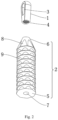
FIG. 1 is a schematic diagram of the structure according to a first embodiment; -
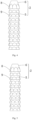
FIG. 2 is a schematic diagram of the structure according to the first embodiment from another perspective; -
FIG. 3 is a schematic diagram of the structure according to a second embodiment; -
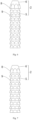
FIG. 4 is a schematic diagram of the structure of an anchor body according to a third embodiment; -
FIG. 5 is a schematic diagram of the structure of an anchor body according to a fourth embodiment; -
FIG. 6 is a schematic diagram of the structure of an anchor body according to a fifth embodiment; -
FIG. 7 is a schematic diagram of the structure of an anchor body according to a sixth embodiment. - List of reference signs: 1. anchor head; 2. anchor body; 3. threading hole; 4. screw hole; 5. side pressing portion; 6. abutment portion; 7. through hole; 8. oblique cuts; 9. longitudinal cut; 10. first arc surface; 11. second arc surface.
- The present application will be described in further detail below with reference to
Figs. 1-7 . - The present application embodiment discloses a suture anchor.
- As shown in
Figs. 1 and2 , a suture anchor includes ananchor head 1 and ananchor body 2, the top of theanchor head 1 is a convex arc shape, athreading hole 3 is formed on the front face of theanchor head 1, and ascrew hole 4 is formed on the bottom of theanchor head 1. - As shown in
Figs. 1 and2 , theanchor body 2 includes a sidepressing portion 5 integrally formed by ten layers of circular truncated cones, and anabutment portion 6 integrally formed on the top of theside pressing portion 5. A throughhole 7 for passing through an anchor operating handle is formed in the middle of theanchor body 2. Theabutment portion 6 has a circular truncated cone shape, and the taper of theabutment portion 6 is greater than that of theside pressing portion 5. - As shown in
Figs. 1 and2 , eightoblique cuts 8 are uniformly formed on a circumference of theabutment portion 6 in a circumferential direction. Each oblique cut 8 has a shallow cutting depth at a position close to the top end of theabutment portion 6, and a deep cutting depth at a position close to the lower end of theabutment portion 6. Eightlongitudinal cuts 9 are uniformly formed on a circumference of each circular truncated cone of theside pressing portion 5 in the circumferential direction, and eachlongitudinal cut 9 cuts the circular truncated cone of theabutment portion 6 in the vertical direction. The positions of thelongitudinal cuts 9 on the adjacent circular truncated cones from top to bottom have a small angular deviation toward the same direction. - Specific use process is as follows.
- In use, the
anchor head 1 and theanchor body 2 are connected to the anchor operating handle, the suture thread is passed through thethreading hole 3, and theanchor head 1 and theanchor body 2 are pushed into a groove opened on the bone with the anchor operating handle. - The outer ring of the
abutment portion 6 abuts on and fits to the inner wall of the bone groove for fixation. Theanchor head 1 abuts on theanchor body 2. The suture thread passes through the bone groove from a position where thelongitudinal cuts 9 are formed on theanchor body 2. Since the positions of thelongitudinal cuts 9 on each layer are deviated relative to each other, when the suture thread is stretched and straightened outwards, the suture thread can pass through a part with a larger gap between theabutment portion 6 and the bone groove, and can also pass through a part with a smaller gap therebetween, so that the suture thread is firmly fixed and cannot be cut off by the edge of the circular truncated cone. - As shown in
Fig. 3 , a suture anchor includes ananchor head 1 and ananchor body 2, the top of theanchor head 1 is a convex arc shape, and athreading hole 3 is formed on the front face of theanchor head 1. Afirst arc surface 10, which is concave from both sides to the middle, is formed on the bottom of theanchor head 1, and ascrew hole 4 is formed in the center of thefirst arc surface 10. - As shown in
Fig. 3 , theanchor body 2 includes a sidepressing portion 5 integrally formed by ten layers of circular truncated cones, and anabutment portion 6 integrally formed on the top of theside pressing portion 5. A throughhole 7 for passing through an anchor operating handle is formed in the middle of theanchor body 2. Theabutment portion 6 has a circular truncated cone shape, and the taper of theabutment portion 6 is greater than that of theside pressing portion 5. Asecond arc surface 11, which protrudes from both sides to the middle, is formed on the top of theabutment portion 6, and thesecond arc surface 11 can abut on and fit with thefirst arc surface 10. - As shown in
Fig. 3 ,oblique cuts 8 are formed on the front and back sides of theabutment portion 6. The oblique cut 8 has a shallow cutting depth at a position close to the top end of theabutment portion 6, and has a deep cutting depth at a position close to the lower end of theabutment portion 6.Longitudinal cuts 9 are formed on both the front and back sides of each circular truncated cone of theside pressing portion 5, and eachlongitudinal cut 9 cuts the circular truncated cone of theabutment portion 6 in the vertical direction. The positions of thelongitudinal cuts 9 on the adjacent circular truncated cones from top to bottom have a small angular deviation toward the same direction. - Specific use process is as follows.
- In use, the
anchor head 1 and theanchor body 2 are connected to the anchor operating handle, the suture thread is passed through thethreading hole 3, and theanchor head 1 and theanchor body 2 are pushed into a groove opened on the bone with the anchor operating handle. - The outer ring of the
abutment portion 6 abuts on and fits to the inner wall of a groove opened on the bone for fixation. When thefirst arc surface 10 abuts on thesecond arc surface 11, a right edge of alongitudinal cut 9 on the circular truncated cone closest to theanchor head 1 directly faces thethreading hole 3, and a left edge of alongitudinal cut 9 on the circular truncated cone furthest from theanchor head 1 directly faces thethreading hole 3. Therefore, when the suture thread is stretched and straightened outwards, the suture thread can pass through a part with a larger gap between theabutment portion 6 and the bone groove, and can also pass through a part with a smaller gap therebetween, so that the suture thread is firmly fixed and cannot be cut off by the edge of the circular truncated cone. - This embodiment differs from the
embodiment 1 is only in theanchor body 2. As shown inFig. 4 , theanchor body 2 includes a sidepressing portion 5 integrally formed by a plurality of layers of circular truncated cones, and anabutment portion 6 integrally formed on the top of theside pressing portion 5. Theabutment portion 6 has a circular truncated cone shape, and the taper of theabutment portion 6 is greater than or equal to the taper of the circular truncated cone of theside pressing portion 5. At least twooblique cuts 8 are uniformly formed on a circumference of theabutment portion 6 in the circumferential direction. Each oblique cut 8 has a shallow cutting depth at a position close to the top end of theabutment portion 6, and has a deep cutting depth at a position close to the lower end of theabutment portion 6.Longitudinal cuts 9, which are equal in number to theoblique cuts 8, are uniformly formed on a circumference of each circular truncated cone of theside pressing portion 5 in the circumferential direction. Eachlongitudinal cut 9 cuts the circular truncated cone of theabutment portion 6 in the vertical direction. From the top view, the positions of thelongitudinal cuts 9 on the adjacent circular truncated cones from top to bottom is deviated by an angle of 5 degrees in the clockwise direction. From the top view, theoblique cuts 8 have an angle of 5 degrees in the counterclockwise direction relative to thelongitudinal cuts 9 on the adjacentside pressing portion 5. - This embodiment differs from the
embodiment 1 is only in theanchor body 2. As shown inFig. 5 , theanchor body 2 includes a sidepressing portion 5 integrally formed by a plurality of layers of circular truncated cones, and anabutment portion 6 integrally formed on the top of theside pressing portion 5. Theabutment portion 6 has a circular truncated cone shape, and the taper of theabutment portion 6 is greater than or equal to the taper of the circular truncated cone of theside pressing portion 5. At least twooblique cuts 8 are uniformly formed on a circumference of theabutment portion 6 in the circumferential direction. Each oblique cut 8 has a shallow cutting depth at a position close to the top end of theabutment portion 6, and has a deep cutting depth at a position close to the lower end of theabutment portion 6.Longitudinal cuts 9, which are equal in number to theoblique cuts 8, are uniformly formed on a circumference of each circular truncated cone of theside pressing portion 5 in the circumferential direction. Eachlongitudinal cut 9 cuts the circular truncated cone of theabutment portion 6 in the vertical direction. From the top view, the positions of thelongitudinal cuts 9 on the adjacent circular truncated cones from top to bottom is deviated by an angle of 10 degrees in the clockwise direction. From the top view, theoblique cuts 8 have an angle of 10 degrees in the counterclockwise direction relative to thelongitudinal cuts 9 on the adjacentside pressing portion 5. - This embodiment differs from the
embodiment 1 is only in theanchor body 2. As shown inFIG. 6 , theanchor body 2 includes a sidepressing portion 5 integrally formed by a plurality of layers of circular truncated cones, and anabutment portion 6 integrally formed on the top of theside pressing portion 5. Theabutment portion 6 has a circular truncated cone shape, and the taper of theabutment portion 6 is greater than or equal to the taper of the circular truncated cone of theside pressing portion 5. At least twooblique cuts 8 are uniformly formed on a circumference of theabutment portion 6 in the circumferential direction. Each oblique cut 8 has a shallow cutting depth at a position close to the top end of theabutment portion 6, and has a deep cutting depth at a position close to the lower end of theabutment portion 6.Longitudinal cuts 9, which are equal in number to theoblique cuts 8, are uniformly formed on a circumference of each circular truncated cone of theside pressing portion 5 in the circumferential direction. Eachlongitudinal cut 9 cuts the circular truncated cone of theabutment portion 6 in the vertical direction. From the top view, the positions of thelongitudinal cuts 9 on the adjacent circular truncated cones from top to bottom is deviated by an angle of 15 degrees in the clockwise direction. From the top view, theoblique cuts 8 have an angle of 15 degrees in the counterclockwise direction relative to thelongitudinal cuts 9 on the adjacentside pressing portion 5. - This embodiment differs from the
embodiment 1 is only in theanchor body 2. As shown inFIG. 7 , theanchor body 2 includes a sidepressing portion 5 integrally formed by a plurality of layers of circular truncated cones, and anabutment portion 6 integrally formed on the top of theside pressing portion 5. Theabutment portion 6 has a circular truncated cone shape, and the taper of theabutment portion 6 is greater than or equal to the taper of the circular truncated cone of theside pressing portion 5. At least twooblique cuts 8 are uniformly formed on a circumference of theabutment portion 6 in the circumferential direction. Each oblique cut 8 has a shallow cutting depth at a position close to the top end of theabutment portion 6, and has a deep cutting depth at a position close to the lower end of theabutment portion 6.Longitudinal cuts 9, which are equal in number to theoblique cuts 8, are uniformly formed on a circumference of each circular truncated cone of theside pressing portion 5 in the circumferential direction. Eachlongitudinal cut 9 cuts the circular truncated cone of theabutment portion 6 in the vertical direction. From the top view, the positions of thelongitudinal cuts 9 on the adjacent circular truncated cones from top to bottom is deviated by an angle of 45 degrees in the counterclockwise direction. From the top view, theoblique cuts 8 have an angle of 45 degrees in the clockwise direction relative to thelongitudinal cuts 9 on the adjacentside pressing portion 5. - The above are the preferred embodiments of the present application, and the protection scope of the present application is not limited accordingly. Therefore, all equivalent changes made according to the structure, shape and principle of the present application should be covered within the scope of the appended claims.
Claims (6)
- A suture anchor, comprising an anchor head (1) and an anchor body (2), wherein a threading hole (3) is formed on the anchor head (1), the anchor body (2) comprises a laterally pressing portion (5) integrally formed by a plurality of layers of circular truncated cones, and at least two opposite longitudinal cuts (9) are formed on each circular truncated cone of the laterally pressing portion (5); from a direction close to the anchor head (1) to a direction away from the anchor head (1), positions of the longitudinal cuts (9) on adjacent circular truncated cones are deviated toward a same side, the anchor body (2) further comprises an abutment portion (6) located at an end of the laterally pressing portion (5) close to the anchor head (1), characterized in that a first arc surface (10) that is concave from both sides to the middle is formed on bottom of the anchor head (1), and a second arc surface (11) that protrudes from both sides to the middle is formed on top of the abutment portion (6), and the second arc surface and the first arc surface (10) fit with each other, wherein the number of longitudinal cuts (9) on each circular truncated cone of the laterally pressing portion (5) is two; in a state where the first arc surface (10) abuts on the second arc surface (11), a side edge of a longitudinal cut (9) on the circular truncated cone nearest to the anchor head (1) directly faces the threading hole (3), and the other side edge of the longitudinal cut (9) on the circular truncated cone furthest from the anchor head (1) directly faces the threading hole (3), and a plurality of oblique cuts (8) are uniformly formed on a circumference of the abutment portion (6) in a circumferential direction, a cutting depth of the oblique cut (8) at a position near a lower end of the abutment portion (6) is greater than a cutting depth at a position near a top end of the abutment portion (6).
- The suture anchor according to claim 1, characterized in that, the positions of the longitudinal cuts (9) on adjacent circular truncated cones are deviated by a same angle in a clockwise or counterclockwise direction from a top view, and a deviation angle of the longitudinal cuts (9) on the adjacent circular truncated cones is from 0 to 45 degrees.
- The suture anchor according to claim 1, characterized in that, at least four longitudinal cuts (9) are formed uniformly on each circular truncated cone of the laterally pressing portion (5) along a circumferential circle.
- The suture anchor according to claim 1, characterized in that, the abutment portion (6) is set to be a circular truncated cone, a taper of the abutment portion (6) is greater than that of the circular truncated cones of the laterally pressing portion (5).
- The suture anchor according to claim 1, characterized in that, the top of the anchor head (1) is a convex arc shape.
- The suture anchor according to claim 1, characterized in that, a screw hole (4) is formed on the bottom of the anchor head (1).
Applications Claiming Priority (2)
| Application Number | Priority Date | Filing Date | Title |
|---|---|---|---|
| CN202110507883.5A CN113288256A (en) | 2021-05-10 | 2021-05-10 | Anchor with wire |
| PCT/CN2021/112401 WO2022236990A1 (en) | 2021-05-10 | 2021-08-13 | Line-leading anchor screw |
Publications (4)
| Publication Number | Publication Date |
|---|---|
| EP4115817A4 EP4115817A4 (en) | 2023-01-11 |
| EP4115817A1 EP4115817A1 (en) | 2023-01-11 |
| EP4115817C0 EP4115817C0 (en) | 2024-12-04 |
| EP4115817B1 true EP4115817B1 (en) | 2024-12-04 |
Family
ID=77321476
Family Applications (1)
| Application Number | Title | Priority Date | Filing Date |
|---|---|---|---|
| EP21798261.0A Active EP4115817B1 (en) | 2021-05-10 | 2021-08-13 | Line-leading anchor screw |
Country Status (5)
| Country | Link |
|---|---|
| US (1) | US12029409B2 (en) |
| EP (1) | EP4115817B1 (en) |
| CN (1) | CN113288256A (en) |
| ES (1) | ES3000096T3 (en) |
| WO (1) | WO2022236990A1 (en) |
Family Cites Families (15)
| Publication number | Priority date | Publication date | Assignee | Title |
|---|---|---|---|---|
| US5464427A (en) * | 1994-10-04 | 1995-11-07 | Synthes (U.S.A.) | Expanding suture anchor |
| US5707395A (en) * | 1997-01-16 | 1998-01-13 | Li Medical Technologies, Inc. | Surgical fastener and method and apparatus for ligament repair |
| US8764797B2 (en) * | 2000-02-02 | 2014-07-01 | Arthrex, Inc. | Suture anchor with insert-molded suture eyelet |
| US6641596B1 (en) * | 2000-10-18 | 2003-11-04 | Ethicon, Inc. | Knotless bioabsorbable suture anchor system and method |
| US6733506B1 (en) * | 2000-11-16 | 2004-05-11 | Ethicon, Inc. | Apparatus and method for attaching soft tissue to bone |
| US7713286B2 (en) * | 2002-11-15 | 2010-05-11 | Linvatec Corporation | Knotless suture anchor |
| US8029536B2 (en) * | 2005-11-14 | 2011-10-04 | Tornier, Inc. | Multiple offset eyelet suture anchor |
| US9855028B2 (en) * | 2012-04-06 | 2018-01-02 | Arthrocare Corporation | Multi-suture knotless anchor for attaching tissue to bone and related method |
| US9192371B2 (en) * | 2013-03-08 | 2015-11-24 | Biomet Sports Medicine, Llc | Knotless suture anchor and method of using same |
| CN207886227U (en) * | 2017-06-09 | 2018-09-21 | 丁伟 | A kind of medical holdfast |
| CN107569264B (en) * | 2017-10-18 | 2024-06-21 | 运怡(北京)医疗器械有限公司 | Knotless suture anchor |
| CN107582118A (en) * | 2017-10-18 | 2018-01-16 | 运怡(北京)医疗器械有限公司 | A kind of half-thread band line holdfast |
| CN110840500A (en) * | 2019-09-26 | 2020-02-28 | 江苏百易得医疗科技有限公司 | Anchor with wire |
| CN211674388U (en) * | 2020-02-14 | 2020-10-16 | 长春圣博玛生物材料有限公司 | a knotless anchor |
| CN112494089B (en) * | 2020-11-17 | 2022-09-23 | 北京市春立正达医疗器械股份有限公司 | Exempt from to tie a knot anchor and anchor implantation apparatus |
-
2021
- 2021-05-10 CN CN202110507883.5A patent/CN113288256A/en active Pending
- 2021-08-13 WO PCT/CN2021/112401 patent/WO2022236990A1/en not_active Ceased
- 2021-08-13 EP EP21798261.0A patent/EP4115817B1/en active Active
- 2021-08-13 ES ES21798261T patent/ES3000096T3/en active Active
- 2021-11-10 US US17/523,897 patent/US12029409B2/en active Active
Also Published As
| Publication number | Publication date |
|---|---|
| CN113288256A (en) | 2021-08-24 |
| EP4115817C0 (en) | 2024-12-04 |
| ES3000096T3 (en) | 2025-02-27 |
| EP4115817A4 (en) | 2023-01-11 |
| US12029409B2 (en) | 2024-07-09 |
| US20220354481A1 (en) | 2022-11-10 |
| WO2022236990A1 (en) | 2022-11-17 |
| EP4115817A1 (en) | 2023-01-11 |
Similar Documents
| Publication | Publication Date | Title |
|---|---|---|
| US10537319B2 (en) | Suture anchor | |
| EP1917915B1 (en) | Suture anchor with pulley | |
| EP1300115B1 (en) | Suture anchor | |
| US7883528B2 (en) | Fully threaded suture anchor with insert-molded suture | |
| EP2806813B1 (en) | Compression screw system | |
| US5964783A (en) | Suture anchor with insert-molded suture | |
| US9526493B2 (en) | Suture anchor with insert-molded rigid member | |
| US7442202B2 (en) | Suture anchor attached to tissue-fixation disk without top knot | |
| CN103156678B (en) | Unknotted type suture anchor | |
| EP1884213A1 (en) | A bone plate | |
| WO2010059648A2 (en) | Device and method for tendon, ligament or soft tissue repair | |
| US20220370182A1 (en) | Lifting thread with stretchable variable portion | |
| CN115670552A (en) | Hollow two-stage implantable knotless suture anchor | |
| JPH1085225A (en) | Surgical needle with tapered thread | |
| WO2015137882A1 (en) | A system for cosmetic enhancement | |
| KR200343048Y1 (en) | Connecting structure of surgical needle and suture | |
| US12029409B2 (en) | Suture anchor | |
| EP4238518B1 (en) | BONE FIXATION DEVICE | |
| CN1151278A (en) | Induction devices for medical needles | |
| CN119055296A (en) | Expansion type wire anchor fixing device | |
| KR20060059897A (en) | Surgical nail |
Legal Events
| Date | Code | Title | Description |
|---|---|---|---|
| STAA | Information on the status of an ep patent application or granted ep patent |
Free format text: STATUS: UNKNOWN |
|
| STAA | Information on the status of an ep patent application or granted ep patent |
Free format text: STATUS: THE INTERNATIONAL PUBLICATION HAS BEEN MADE |
|
| PUAI | Public reference made under article 153(3) epc to a published international application that has entered the european phase |
Free format text: ORIGINAL CODE: 0009012 |
|
| STAA | Information on the status of an ep patent application or granted ep patent |
Free format text: STATUS: REQUEST FOR EXAMINATION WAS MADE |
|
| STAA | Information on the status of an ep patent application or granted ep patent |
Free format text: STATUS: EXAMINATION IS IN PROGRESS |
|
| 17P | Request for examination filed |
Effective date: 20211109 |
|
| A4 | Supplementary search report drawn up and despatched |
Effective date: 20221010 |
|
| AK | Designated contracting states |
Kind code of ref document: A1 Designated state(s): AL AT BE BG CH CY CZ DE DK EE ES FI FR GB GR HR HU IE IS IT LI LT LU LV MC MK MT NL NO PL PT RO RS SE SI SK SM TR |
|
| 17Q | First examination report despatched |
Effective date: 20230105 |
|
| DAV | Request for validation of the european patent (deleted) | ||
| DAX | Request for extension of the european patent (deleted) | ||
| GRAP | Despatch of communication of intention to grant a patent |
Free format text: ORIGINAL CODE: EPIDOSNIGR1 |
|
| STAA | Information on the status of an ep patent application or granted ep patent |
Free format text: STATUS: GRANT OF PATENT IS INTENDED |
|
| INTG | Intention to grant announced |
Effective date: 20240919 |
|
| GRAS | Grant fee paid |
Free format text: ORIGINAL CODE: EPIDOSNIGR3 |
|
| GRAA | (expected) grant |
Free format text: ORIGINAL CODE: 0009210 |
|
| STAA | Information on the status of an ep patent application or granted ep patent |
Free format text: STATUS: THE PATENT HAS BEEN GRANTED |
|
| AK | Designated contracting states |
Kind code of ref document: B1 Designated state(s): AL AT BE BG CH CY CZ DE DK EE ES FI FR GB GR HR HU IE IS IT LI LT LU LV MC MK MT NL NO PL PT RO RS SE SI SK SM TR |
|
| REG | Reference to a national code |
Ref country code: CH Ref legal event code: EP |
|
| REG | Reference to a national code |
Ref country code: DE Ref legal event code: R096 Ref document number: 602021022984 Country of ref document: DE |
|
| REG | Reference to a national code |
Ref country code: IE Ref legal event code: FG4D |
|
| U01 | Request for unitary effect filed |
Effective date: 20241216 |
|
| U07 | Unitary effect registered |
Designated state(s): AT BE BG DE DK EE FI FR IT LT LU LV MT NL PT RO SE SI Effective date: 20250108 |
|
| REG | Reference to a national code |
Ref country code: ES Ref legal event code: FG2A Ref document number: 3000096 Country of ref document: ES Kind code of ref document: T3 Effective date: 20250227 |
|
| PG25 | Lapsed in a contracting state [announced via postgrant information from national office to epo] |
Ref country code: HR Free format text: LAPSE BECAUSE OF FAILURE TO SUBMIT A TRANSLATION OF THE DESCRIPTION OR TO PAY THE FEE WITHIN THE PRESCRIBED TIME-LIMIT Effective date: 20241204 |
|
| PG25 | Lapsed in a contracting state [announced via postgrant information from national office to epo] |
Ref country code: NO Free format text: LAPSE BECAUSE OF FAILURE TO SUBMIT A TRANSLATION OF THE DESCRIPTION OR TO PAY THE FEE WITHIN THE PRESCRIBED TIME-LIMIT Effective date: 20250304 |
|
| PG25 | Lapsed in a contracting state [announced via postgrant information from national office to epo] |
Ref country code: GR Free format text: LAPSE BECAUSE OF FAILURE TO SUBMIT A TRANSLATION OF THE DESCRIPTION OR TO PAY THE FEE WITHIN THE PRESCRIBED TIME-LIMIT Effective date: 20250305 |
|
| PG25 | Lapsed in a contracting state [announced via postgrant information from national office to epo] |
Ref country code: RS Free format text: LAPSE BECAUSE OF FAILURE TO SUBMIT A TRANSLATION OF THE DESCRIPTION OR TO PAY THE FEE WITHIN THE PRESCRIBED TIME-LIMIT Effective date: 20250304 |
|
| PG25 | Lapsed in a contracting state [announced via postgrant information from national office to epo] |
Ref country code: SM Free format text: LAPSE BECAUSE OF FAILURE TO SUBMIT A TRANSLATION OF THE DESCRIPTION OR TO PAY THE FEE WITHIN THE PRESCRIBED TIME-LIMIT Effective date: 20241204 |
|
| PG25 | Lapsed in a contracting state [announced via postgrant information from national office to epo] |
Ref country code: PL Free format text: LAPSE BECAUSE OF FAILURE TO SUBMIT A TRANSLATION OF THE DESCRIPTION OR TO PAY THE FEE WITHIN THE PRESCRIBED TIME-LIMIT Effective date: 20241204 |
|
| PG25 | Lapsed in a contracting state [announced via postgrant information from national office to epo] |
Ref country code: IS Free format text: LAPSE BECAUSE OF FAILURE TO SUBMIT A TRANSLATION OF THE DESCRIPTION OR TO PAY THE FEE WITHIN THE PRESCRIBED TIME-LIMIT Effective date: 20250404 |
|
| PG25 | Lapsed in a contracting state [announced via postgrant information from national office to epo] |
Ref country code: SK Free format text: LAPSE BECAUSE OF FAILURE TO SUBMIT A TRANSLATION OF THE DESCRIPTION OR TO PAY THE FEE WITHIN THE PRESCRIBED TIME-LIMIT Effective date: 20241204 |
|
| PG25 | Lapsed in a contracting state [announced via postgrant information from national office to epo] |
Ref country code: CZ Free format text: LAPSE BECAUSE OF FAILURE TO SUBMIT A TRANSLATION OF THE DESCRIPTION OR TO PAY THE FEE WITHIN THE PRESCRIBED TIME-LIMIT Effective date: 20241204 |
|
| U20 | Renewal fee for the european patent with unitary effect paid |
Year of fee payment: 5 Effective date: 20250827 |
|
| PGFP | Annual fee paid to national office [announced via postgrant information from national office to epo] |
Ref country code: ES Payment date: 20250926 Year of fee payment: 5 |
|
| PLBE | No opposition filed within time limit |
Free format text: ORIGINAL CODE: 0009261 |
|
| STAA | Information on the status of an ep patent application or granted ep patent |
Free format text: STATUS: NO OPPOSITION FILED WITHIN TIME LIMIT |
|
| REG | Reference to a national code |
Ref country code: CH Ref legal event code: L10 Free format text: ST27 STATUS EVENT CODE: U-0-0-L10-L00 (AS PROVIDED BY THE NATIONAL OFFICE) Effective date: 20251015 |
|
| PGFP | Annual fee paid to national office [announced via postgrant information from national office to epo] |
Ref country code: GB Payment date: 20250820 Year of fee payment: 5 |
|
| 26N | No opposition filed |
Effective date: 20250905 |
|
| REG | Reference to a national code |
Ref country code: CH Ref legal event code: H13 Free format text: ST27 STATUS EVENT CODE: U-0-0-H10-H13 (AS PROVIDED BY THE NATIONAL OFFICE) Effective date: 20260324 |
|
| PG25 | Lapsed in a contracting state [announced via postgrant information from national office to epo] |
Ref country code: MC Free format text: LAPSE BECAUSE OF FAILURE TO SUBMIT A TRANSLATION OF THE DESCRIPTION OR TO PAY THE FEE WITHIN THE PRESCRIBED TIME-LIMIT Effective date: 20241204 |
|
| PG25 | Lapsed in a contracting state [announced via postgrant information from national office to epo] |
Ref country code: CH Free format text: LAPSE BECAUSE OF NON-PAYMENT OF DUE FEES Effective date: 20250831 |
|
| PG25 | Lapsed in a contracting state [announced via postgrant information from national office to epo] |
Ref country code: IE Free format text: LAPSE BECAUSE OF NON-PAYMENT OF DUE FEES Effective date: 20250813 |