EP4115772A1 - Coupling device for sofa and armchair backrests - Google Patents
Coupling device for sofa and armchair backrests Download PDFInfo
- Publication number
- EP4115772A1 EP4115772A1 EP22382162.0A EP22382162A EP4115772A1 EP 4115772 A1 EP4115772 A1 EP 4115772A1 EP 22382162 A EP22382162 A EP 22382162A EP 4115772 A1 EP4115772 A1 EP 4115772A1
- Authority
- EP
- European Patent Office
- Prior art keywords
- truncated cone
- shaped part
- sofa
- armchair
- plate
- Prior art date
- Legal status (The legal status is an assumption and is not a legal conclusion. Google has not performed a legal analysis and makes no representation as to the accuracy of the status listed.)
- Granted
Links
Images




Classifications
-
- A—HUMAN NECESSITIES
- A47—FURNITURE; DOMESTIC ARTICLES OR APPLIANCES; COFFEE MILLS; SPICE MILLS; SUCTION CLEANERS IN GENERAL
- A47C—CHAIRS; SOFAS; BEDS
- A47C4/00—Foldable, collapsible or dismountable chairs
- A47C4/02—Dismountable chairs
-
- A—HUMAN NECESSITIES
- A47—FURNITURE; DOMESTIC ARTICLES OR APPLIANCES; COFFEE MILLS; SPICE MILLS; SUCTION CLEANERS IN GENERAL
- A47C—CHAIRS; SOFAS; BEDS
- A47C17/00—Sofas; Couches; Beds
- A47C17/02—Sofas, couches, settees, or the like, without movable parts
-
- A—HUMAN NECESSITIES
- A47—FURNITURE; DOMESTIC ARTICLES OR APPLIANCES; COFFEE MILLS; SPICE MILLS; SUCTION CLEANERS IN GENERAL
- A47B—TABLES; DESKS; OFFICE FURNITURE; CABINETS; DRAWERS; GENERAL DETAILS OF FURNITURE
- A47B2230/00—Furniture jointing; Furniture with such jointing
- A47B2230/0074—Mortise and tenon joints or the like including some general male and female connections
-
- F—MECHANICAL ENGINEERING; LIGHTING; HEATING; WEAPONS; BLASTING
- F16—ENGINEERING ELEMENTS AND UNITS; GENERAL MEASURES FOR PRODUCING AND MAINTAINING EFFECTIVE FUNCTIONING OF MACHINES OR INSTALLATIONS; THERMAL INSULATION IN GENERAL
- F16B—DEVICES FOR FASTENING OR SECURING CONSTRUCTIONAL ELEMENTS OR MACHINE PARTS TOGETHER, e.g. NAILS, BOLTS, CIRCLIPS, CLAMPS, CLIPS OR WEDGES; JOINTS OR JOINTING
- F16B12/00—Jointing of furniture or the like, e.g. hidden from exterior
- F16B12/10—Jointing of furniture or the like, e.g. hidden from exterior using pegs, bolts, tenons, clamps, clips, or the like
- F16B12/12—Jointing of furniture or the like, e.g. hidden from exterior using pegs, bolts, tenons, clamps, clips, or the like for non-metal furniture parts, e.g. made of wood, of plastics
- F16B12/125—Jointing of furniture or the like, e.g. hidden from exterior using pegs, bolts, tenons, clamps, clips, or the like for non-metal furniture parts, e.g. made of wood, of plastics using mortise and tenon joints
-
- F—MECHANICAL ENGINEERING; LIGHTING; HEATING; WEAPONS; BLASTING
- F16—ENGINEERING ELEMENTS AND UNITS; GENERAL MEASURES FOR PRODUCING AND MAINTAINING EFFECTIVE FUNCTIONING OF MACHINES OR INSTALLATIONS; THERMAL INSULATION IN GENERAL
- F16B—DEVICES FOR FASTENING OR SECURING CONSTRUCTIONAL ELEMENTS OR MACHINE PARTS TOGETHER, e.g. NAILS, BOLTS, CIRCLIPS, CLAMPS, CLIPS OR WEDGES; JOINTS OR JOINTING
- F16B12/00—Jointing of furniture or the like, e.g. hidden from exterior
- F16B12/10—Jointing of furniture or the like, e.g. hidden from exterior using pegs, bolts, tenons, clamps, clips, or the like
- F16B12/12—Jointing of furniture or the like, e.g. hidden from exterior using pegs, bolts, tenons, clamps, clips, or the like for non-metal furniture parts, e.g. made of wood, of plastics
- F16B12/20—Jointing of furniture or the like, e.g. hidden from exterior using pegs, bolts, tenons, clamps, clips, or the like for non-metal furniture parts, e.g. made of wood, of plastics using clamps, clips, wedges, sliding bolts, or the like
Definitions
- This invention relates to a coupling device for sofa and/or armchair backrests of the relaxation type, which allows their assembly and disassembly operations to be simplified.
- sofas or armchairs equipped with relaxation mechanisms which have different types of openings configured to move the front of the sofa or armchair forward, transforming the front of the sofa or armchair into a footrest and tilting the backrest to adopt a comfortable way of resting in the reclined position.
- the mechanism described has two major problems.
- the first technical problem is that the female guide is located in a place with little or no accessibility and/or visibility. This means that -in many cases- when trying to insert the plates into the female guides they do not coincide, which may mean that one of the guides might fit, but not the other. This fact can go undetected, which is why the mechanism may break. To prevent this, in many cases it is decided to send the sofa or armchair from the factory already assembled, with the added cost that this entails.
- the second problem relates to a metal strap that has the female guide on its upper part configured as a stop for the aforementioned guide.
- This strap is a kind of latch which, when the plate is fully inserted, it makes a click that prevents the backrest becoming detached during use.
- this technical solution is very problematic, as every time it is necessary to remove the backrest to carry out inspections or repairs -or because one of the sides has not entered properly, as mentioned above- the operation is extremely complex and requires great skill to perform this operation correctly. Furthermore, it is an operation that is not without danger for the operators, finger injuries and broken nails being common.
- a coupling mechanism for sofas or relaxation-type armchair backrests is needed that facilitates and simplifies the aforementioned coupling, so that its assembly and disassembly is simple, efficient and free from physical risks for the operators.
- an object of this invention is a coupling mechanism for sofa or relaxation-type armchairs which allows its assembly operation to be simplified in accordance with the mechanism of claim 1.
- Particular solutions of this invention are described in the dependent claims.
- the mechanism of the invention is configured as a truncated cone-shaped part configured to guide the plate so that it guides or embeds the plate so that it couples properly with the female guide.
- the lower width of the truncated cone-shaped part is able to absorb the possible differences in width that the plates of the backrest may present, since the plates, being pieces made from sheet metal, may present a certain flexibility and oscillate slightly towards both sides, above all, when the width of the sofa or armchair is greater. Therefore, thanks to the truncated cone-shaped part, -which acts like a funnel- the operation to fit the plates into the guides is achieved easily, errors are avoided, and the assembly process of the sofa or armchair is consequently simplified.
- the truncated cone-shaped part avoids the strap or latch of the systems described in the state of the art. Therefore, the truncated cone-shaped part is configured as a new backrest retention system so that it cannot become detached, making the strap, which is responsible for many injuries to operators' fingers, unnecessary.
- the coupling mechanism comprises a truncated cone-shaped part (1) which is coupled to the female guide (2) and which, in turn, is coupled to the plate (3).
- the truncated cone-shaped part (10) is more elongated and configured to replace the female guide (2) and is therefore coupled directly to the plate (3).
- the coupling mechanism of the invention comprises a truncated cone-shaped part (1) which is hollow and open at its upper and lower ends, such that the lower end (1b) is wider than the upper end (1a).
- the lower end (1b) has an inclined flap (1c) which is configured to guide the plate (3) during the assembly operation so that said plate (3) can be inserted into the female guide (2) correctly, as seen better in figure 2 .
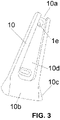
- Figure 3 shows the second embodiment of the coupling mechanism of the invention comprising a truncated cone-shaped part (10) which, as in the first embodiment, is a hollow piece and open at its upper and lower ends, such that the lower end (10b) is wider than the upper end (10a).
- the lower end (10b) has a flap (10c) which is configured to guide the plate (3) during the assembly operation, as seen better in figure 4 or figure 5 .
- the truncated cone-shaped part (1,10) comprises an open side area (1d, 10d) which facilitates the subsequent assembly of the mechanism, as well as an internal protrusion (1e, 10e) located on the inner surface close to the upper end (1a,10a) of the truncated cone-shaped part (1,10) and which is configured to prevent the piece (1,10) from becoming detached from the plate (3) when assembled or in the position of use.
- the only practically appreciable difference between the first and second embodiment of the truncated cone-shaped part (1,10) is its length, understood as the measured distance between the upper end (1a,10a) and the lower end (1b,10b), and that it is considerably greater in the second embodiment so that it can act directly as a guide for the plate (3), replacing the female plate (2) of the first practical embodiment.
- the truncated cone-shaped part (1,10) in both practical embodiments, allows for the plate (3) to be guided or embedded for correct coupling with the female guide (2) or in the truncated cone-shaped part (10) itself in the second embodiment.
- the lower width of the truncated cone-shaped part (1,10) is able to absorb the possible differences in width that the two plates (3) of the backrest may present and facilitate their assembly.
Landscapes
- Health & Medical Sciences (AREA)
- General Health & Medical Sciences (AREA)
- Nursing (AREA)
- Chairs For Special Purposes, Such As Reclining Chairs (AREA)
Abstract
Description
- This invention relates to a coupling device for sofa and/or armchair backrests of the relaxation type, which allows their assembly and disassembly operations to be simplified.
- In the state of the prior art, sofas or armchairs equipped with relaxation mechanisms are known, which have different types of openings configured to move the front of the sofa or armchair forward, transforming the front of the sofa or armchair into a footrest and tilting the backrest to adopt a comfortable way of resting in the reclined position.
- These types of mechanisms have, on their rear part, plates on both sides that serve to couple the backrests of said sofas or armchairs. These plates are designed to be coupled in female guides that are placed inside the frame of the backrest. With this system, it is possible to send the armchair or sofa disassembled, thanks to which it takes up less space and prevents problems during transport. In addition, this assembly does not require tools nor additional screws and bolts.
- The mechanism described has two major problems. The first technical problem is that the female guide is located in a place with little or no accessibility and/or visibility. This means that -in many cases- when trying to insert the plates into the female guides they do not coincide, which may mean that one of the guides might fit, but not the other. This fact can go undetected, which is why the mechanism may break. To prevent this, in many cases it is decided to send the sofa or armchair from the factory already assembled, with the added cost that this entails.
- The second problem relates to a metal strap that has the female guide on its upper part configured as a stop for the aforementioned guide. This strap is a kind of latch which, when the plate is fully inserted, it makes a click that prevents the backrest becoming detached during use. However, this technical solution is very problematic, as every time it is necessary to remove the backrest to carry out inspections or repairs -or because one of the sides has not entered properly, as mentioned above- the operation is extremely complex and requires great skill to perform this operation correctly. Furthermore, it is an operation that is not without danger for the operators, finger injuries and broken nails being common.
- Therefore, a coupling mechanism for sofas or relaxation-type armchair backrests is needed that facilitates and simplifies the aforementioned coupling, so that its assembly and disassembly is simple, efficient and free from physical risks for the operators.
- As previously indicated, an object of this invention is a coupling mechanism for sofa or relaxation-type armchairs which allows its assembly operation to be simplified in accordance with the mechanism of
claim 1. Particular solutions of this invention are described in the dependent claims. - More specifically, the mechanism of the invention is configured as a truncated cone-shaped part configured to guide the plate so that it guides or embeds the plate so that it couples properly with the female guide. In this way, the disadvantages described in the state of the art are avoided. Thus, the lower width of the truncated cone-shaped part is able to absorb the possible differences in width that the plates of the backrest may present, since the plates, being pieces made from sheet metal, may present a certain flexibility and oscillate slightly towards both sides, above all, when the width of the sofa or armchair is greater. Therefore, thanks to the truncated cone-shaped part, -which acts like a funnel- the operation to fit the plates into the guides is achieved easily, errors are avoided, and the assembly process of the sofa or armchair is consequently simplified.
- Finally, another additional advantage of using the truncated cone-shaped part is that it avoids the strap or latch of the systems described in the state of the art. Therefore, the truncated cone-shaped part is configured as a new backrest retention system so that it cannot become detached, making the strap, which is responsible for many injuries to operators' fingers, unnecessary.
- In order to supplement this description and for the purpose of helping with a better understanding of the characteristics of the invention, said description is accompanied by, as an integral part of it, a set of drawings in which the following is shown for illustrative and nonlimiting purposes:
-
Figure 1 - An isolated perspective view of a first practical embodiment of the truncated cone-shaped part that forms part of the coupling mechanism for sofa and armchair backrests, which is the object of this invention. -
Figure 2 - A perspective and sectional view of the truncated cone-shaped part offigure 1 coupled to the female guide and on the plate to form the coupling mechanism in the position of use. -
Figure 3 - An isolated perspective view of a second practical embodiment of the truncated cone-shaped part that forms part of the coupling mechanism for sofa and armchair backrests, which is the object of this invention. -
Figure 4 - A partial view of the truncated cone-shaped part offigure 3 configured as a guide coupled to the coupling mechanism in the position of use. -
Figure 5 - A complete view of the relaxation mechanism of a sofa or armchair, with the truncated cone-shaped part offigures 3 and4 coupled. - As can be seen in the attached figures, this invention can be realised in two practical embodiments. In a first practical embodiment (
figures 1 and2 ) the coupling mechanism comprises a truncated cone-shaped part (1) which is coupled to the female guide (2) and which, in turn, is coupled to the plate (3). In the second practical embodiment (figures 3 to 5 ), the truncated cone-shaped part (10) is more elongated and configured to replace the female guide (2) and is therefore coupled directly to the plate (3). - With reference to
figure 1 , the coupling mechanism of the invention comprises a truncated cone-shaped part (1) which is hollow and open at its upper and lower ends, such that the lower end (1b) is wider than the upper end (1a). In addition, the lower end (1b) has an inclined flap (1c) which is configured to guide the plate (3) during the assembly operation so that said plate (3) can be inserted into the female guide (2) correctly, as seen better infigure 2 . -
Figure 3 shows the second embodiment of the coupling mechanism of the invention comprising a truncated cone-shaped part (10) which, as in the first embodiment, is a hollow piece and open at its upper and lower ends, such that the lower end (10b) is wider than the upper end (10a). In addition, the lower end (10b) has a flap (10c) which is configured to guide the plate (3) during the assembly operation, as seen better infigure 4 orfigure 5 . - In both embodiments, the truncated cone-shaped part (1,10) comprises an open side area (1d, 10d) which facilitates the subsequent assembly of the mechanism, as well as an internal protrusion (1e, 10e) located on the inner surface close to the upper end (1a,10a) of the truncated cone-shaped part (1,10) and which is configured to prevent the piece (1,10) from becoming detached from the plate (3) when assembled or in the position of use.
- Therefore, the only practically appreciable difference between the first and second embodiment of the truncated cone-shaped part (1,10) is its length, understood as the measured distance between the upper end (1a,10a) and the lower end (1b,10b), and that it is considerably greater in the second embodiment so that it can act directly as a guide for the plate (3), replacing the female plate (2) of the first practical embodiment.
- In short, the truncated cone-shaped part (1,10) in both practical embodiments, allows for the plate (3) to be guided or embedded for correct coupling with the female guide (2) or in the truncated cone-shaped part (10) itself in the second embodiment. Thus, the lower width of the truncated cone-shaped part (1,10) is able to absorb the possible differences in width that the two plates (3) of the backrest may present and facilitate their assembly.
- In addition, as the truncated cone-shaped parts (1,10) are made of injected plastic, a better grip is achieved and, in the event of needing to remove the backrest, only slight pressure will be required to release the internal protrusion (1e, 10e) from the corresponding retaining hole of the plate (3).
Claims (4)
- Coupling device for sofa and armchair backrests including a relaxation mechanism configured to move the front of the sofa or armchair forward, transforming the front of the sofa or armchair into a footrest and tilting the backrest which is characterised in that it comprises at least one truncated cone-shaped part (1,10) that can be coupled to at least one plate (3) of the relaxation mechanism, wherein said truncated cone-shaped part (1,10) comprises an inclined flap (1c,10c) at its lower end (1b), as well as an internal protrusion (1e, 10e) located on the inner surface close to the upper end (1a,10a) of the truncated cone-shaped part (1,10).
- The coupling device of claim 1 wherein the truncated cone-shaped part (1) is coupled to a female guide (2) of the relaxation mechanism to be coupled to the plate (3).
- The coupling device of claim 1 wherein the truncated cone-shaped part (10) is configured as a guide for the plate (3) in its assembly operation.
- The device according to any of claims 1 to 3 wherein the truncated cone-shaped part (1,10) is made of injected plastic.
Applications Claiming Priority (1)
| Application Number | Priority Date | Filing Date | Title |
|---|---|---|---|
| ES202131430U ES1277840Y (en) | 2021-07-08 | 2021-07-08 | COUPLING DEVICE FOR THE BACKREST OF SOFAS AND ARMCHAIRS |
Publications (3)
| Publication Number | Publication Date |
|---|---|
| EP4115772A1 true EP4115772A1 (en) | 2023-01-11 |
| EP4115772C0 EP4115772C0 (en) | 2025-10-29 |
| EP4115772B1 EP4115772B1 (en) | 2025-10-29 |
Family
ID=77710091
Family Applications (1)
| Application Number | Title | Priority Date | Filing Date |
|---|---|---|---|
| EP22382162.0A Active EP4115772B1 (en) | 2021-07-08 | 2022-02-25 | Coupling device for sofa and armchair backrests |
Country Status (2)
| Country | Link |
|---|---|
| EP (1) | EP4115772B1 (en) |
| ES (2) | ES1277840Y (en) |
Citations (3)
| Publication number | Priority date | Publication date | Assignee | Title |
|---|---|---|---|---|
| US20040155509A1 (en) * | 2003-02-07 | 2004-08-12 | Smith Danny R. | Knock-down furniture bracket |
| EP1978195A1 (en) * | 2007-03-31 | 2008-10-08 | Hettich Franke GmbH & Co. KG | Clip fitting |
| US20160348705A1 (en) * | 2015-05-28 | 2016-12-01 | Stafast Products, Inc. | Furniture connection bracket |
-
2021
- 2021-07-08 ES ES202131430U patent/ES1277840Y/en active Active
-
2022
- 2022-02-25 ES ES22382162T patent/ES3054738T3/en active Active
- 2022-02-25 EP EP22382162.0A patent/EP4115772B1/en active Active
Patent Citations (3)
| Publication number | Priority date | Publication date | Assignee | Title |
|---|---|---|---|---|
| US20040155509A1 (en) * | 2003-02-07 | 2004-08-12 | Smith Danny R. | Knock-down furniture bracket |
| EP1978195A1 (en) * | 2007-03-31 | 2008-10-08 | Hettich Franke GmbH & Co. KG | Clip fitting |
| US20160348705A1 (en) * | 2015-05-28 | 2016-12-01 | Stafast Products, Inc. | Furniture connection bracket |
Also Published As
| Publication number | Publication date |
|---|---|
| ES3054738T3 (en) | 2026-02-05 |
| EP4115772C0 (en) | 2025-10-29 |
| ES1277840U (en) | 2021-09-17 |
| EP4115772B1 (en) | 2025-10-29 |
| ES1277840Y (en) | 2021-12-10 |
Similar Documents
| Publication | Publication Date | Title |
|---|---|---|
| US8295055B2 (en) | Locking assembly for locking an electronics card to a rack | |
| US10383723B2 (en) | Intraocular lens injector and intraocular lens injection device | |
| EP2503648B1 (en) | Connector position assurance device | |
| US20180067269A1 (en) | Fiber Optic Ferrule with Rear Holes to Align A Guide Pin Clamp with Field Changeable Guide Pins | |
| JP5934447B2 (en) | Lock system for locking medical devices | |
| US5830000A (en) | Locking lever connector mechanism | |
| EP0378909A2 (en) | Trouble-free connector with lock mechanism | |
| US5826840A (en) | Computer keyboard support | |
| EP3412405A1 (en) | Key blank dispensing system | |
| US20200003350A1 (en) | Quick connection system and method for implementation | |
| CN106233006B (en) | Fitting member and replacement unit for elongate member | |
| EP4115772B1 (en) | Coupling device for sofa and armchair backrests | |
| US6398575B1 (en) | Locking device for electrical connector | |
| CN113271818B (en) | Seat chassis | |
| EP3760943B1 (en) | Air conditioner base and air conditioner | |
| EP2973882B1 (en) | Latching connector assembly | |
| JPH0950858A (en) | Connector mating structure | |
| JP2002369728A (en) | Headrest support | |
| JP2002198121A (en) | Split connector | |
| JPH0955262A (en) | Connector mating structure | |
| CN111976156B (en) | Connecting device for interconnecting two parts made of plastic material | |
| JP5079358B2 (en) | Headrest | |
| US12186546B2 (en) | Medical device loading systems, devices, and methods | |
| CN215173106U (en) | Automatic safety coupling who connects | |
| US20240088605A1 (en) | Modular cable exit assembly |
Legal Events
| Date | Code | Title | Description |
|---|---|---|---|
| PUAI | Public reference made under article 153(3) epc to a published international application that has entered the european phase |
Free format text: ORIGINAL CODE: 0009012 |
|
| STAA | Information on the status of an ep patent application or granted ep patent |
Free format text: STATUS: REQUEST FOR EXAMINATION WAS MADE |
|
| 17P | Request for examination filed |
Effective date: 20220428 |
|
| AK | Designated contracting states |
Kind code of ref document: A1 Designated state(s): AL AT BE BG CH CY CZ DE DK EE ES FI FR GB GR HR HU IE IS IT LI LT LU LV MC MK MT NL NO PL PT RO RS SE SI SK SM TR |
|
| STAA | Information on the status of an ep patent application or granted ep patent |
Free format text: STATUS: EXAMINATION IS IN PROGRESS |
|
| 17Q | First examination report despatched |
Effective date: 20231017 |
|
| GRAP | Despatch of communication of intention to grant a patent |
Free format text: ORIGINAL CODE: EPIDOSNIGR1 |
|
| STAA | Information on the status of an ep patent application or granted ep patent |
Free format text: STATUS: GRANT OF PATENT IS INTENDED |
|
| RIC1 | Information provided on ipc code assigned before grant |
Ipc: F16B 12/12 20060101ALN20250513BHEP Ipc: F16B 12/20 20060101ALN20250513BHEP Ipc: A47C 7/42 20060101AFI20250513BHEP |
|
| INTG | Intention to grant announced |
Effective date: 20250602 |
|
| GRAS | Grant fee paid |
Free format text: ORIGINAL CODE: EPIDOSNIGR3 |
|
| GRAA | (expected) grant |
Free format text: ORIGINAL CODE: 0009210 |
|
| STAA | Information on the status of an ep patent application or granted ep patent |
Free format text: STATUS: THE PATENT HAS BEEN GRANTED |
|
| AK | Designated contracting states |
Kind code of ref document: B1 Designated state(s): AL AT BE BG CH CY CZ DE DK EE ES FI FR GB GR HR HU IE IS IT LI LT LU LV MC MK MT NL NO PL PT RO RS SE SI SK SM TR |
|
| REG | Reference to a national code |
Ref country code: CH Ref legal event code: F10 Free format text: ST27 STATUS EVENT CODE: U-0-0-F10-F00 (AS PROVIDED BY THE NATIONAL OFFICE) Effective date: 20251029 Ref country code: GB Ref legal event code: FG4D |
|
| REG | Reference to a national code |
Ref country code: DE Ref legal event code: R096 Ref document number: 602022023900 Country of ref document: DE |
|
| REG | Reference to a national code |
Ref country code: IE Ref legal event code: FG4D |
|
| U01 | Request for unitary effect filed |
Effective date: 20251120 |
|
| U07 | Unitary effect registered |
Designated state(s): AT BE BG DE DK EE FI FR IT LT LU LV MT NL PT RO SE SI Effective date: 20251127 |
|
| REG | Reference to a national code |
Ref country code: ES Ref legal event code: FG2A Ref document number: 3054738 Country of ref document: ES Kind code of ref document: T3 Effective date: 20260205 |
|
| U20 | Renewal fee for the european patent with unitary effect paid |
Year of fee payment: 5 Effective date: 20260209 |
|
| PG25 | Lapsed in a contracting state [announced via postgrant information from national office to epo] |
Ref country code: NO Free format text: LAPSE BECAUSE OF FAILURE TO SUBMIT A TRANSLATION OF THE DESCRIPTION OR TO PAY THE FEE WITHIN THE PRESCRIBED TIME-LIMIT Effective date: 20260129 |
|
| PG25 | Lapsed in a contracting state [announced via postgrant information from national office to epo] |
Ref country code: HR Free format text: LAPSE BECAUSE OF FAILURE TO SUBMIT A TRANSLATION OF THE DESCRIPTION OR TO PAY THE FEE WITHIN THE PRESCRIBED TIME-LIMIT Effective date: 20251029 |
|
| PG25 | Lapsed in a contracting state [announced via postgrant information from national office to epo] |
Ref country code: RS Free format text: LAPSE BECAUSE OF FAILURE TO SUBMIT A TRANSLATION OF THE DESCRIPTION OR TO PAY THE FEE WITHIN THE PRESCRIBED TIME-LIMIT Effective date: 20260129 |
|
| PG25 | Lapsed in a contracting state [announced via postgrant information from national office to epo] |
Ref country code: IS Free format text: LAPSE BECAUSE OF FAILURE TO SUBMIT A TRANSLATION OF THE DESCRIPTION OR TO PAY THE FEE WITHIN THE PRESCRIBED TIME-LIMIT Effective date: 20260228 |
|
| PG25 | Lapsed in a contracting state [announced via postgrant information from national office to epo] |
Ref country code: PL Free format text: LAPSE BECAUSE OF FAILURE TO SUBMIT A TRANSLATION OF THE DESCRIPTION OR TO PAY THE FEE WITHIN THE PRESCRIBED TIME-LIMIT Effective date: 20251029 |
|
| PG25 | Lapsed in a contracting state [announced via postgrant information from national office to epo] |
Ref country code: SM Free format text: LAPSE BECAUSE OF FAILURE TO SUBMIT A TRANSLATION OF THE DESCRIPTION OR TO PAY THE FEE WITHIN THE PRESCRIBED TIME-LIMIT Effective date: 20251029 |
|
| PGFP | Annual fee paid to national office [announced via postgrant information from national office to epo] |
Ref country code: ES Payment date: 20260507 Year of fee payment: 5 |
|
| PG25 | Lapsed in a contracting state [announced via postgrant information from national office to epo] |
Ref country code: CZ Free format text: LAPSE BECAUSE OF FAILURE TO SUBMIT A TRANSLATION OF THE DESCRIPTION OR TO PAY THE FEE WITHIN THE PRESCRIBED TIME-LIMIT Effective date: 20251029 |
|
| PG25 | Lapsed in a contracting state [announced via postgrant information from national office to epo] |
Ref country code: SK Free format text: LAPSE BECAUSE OF FAILURE TO SUBMIT A TRANSLATION OF THE DESCRIPTION OR TO PAY THE FEE WITHIN THE PRESCRIBED TIME-LIMIT Effective date: 20251029 |