EP4115755B1 - Electronic vaporization device and vaporizer thereof - Google Patents
Electronic vaporization device and vaporizer thereof Download PDFInfo
- Publication number
- EP4115755B1 EP4115755B1 EP22182225.7A EP22182225A EP4115755B1 EP 4115755 B1 EP4115755 B1 EP 4115755B1 EP 22182225 A EP22182225 A EP 22182225A EP 4115755 B1 EP4115755 B1 EP 4115755B1
- Authority
- EP
- European Patent Office
- Prior art keywords
- liquid guide
- air outlet
- outlet channel
- vaporizer
- vaporization
- Prior art date
- Legal status (The legal status is an assumption and is not a legal conclusion. Google has not performed a legal analysis and makes no representation as to the accuracy of the status listed.)
- Active
Links
Images
Classifications
-
- A—HUMAN NECESSITIES
- A24—TOBACCO; CIGARS; CIGARETTES; SIMULATED SMOKING DEVICES; SMOKERS' REQUISITES
- A24F—SMOKERS' REQUISITES; MATCH BOXES; SIMULATED SMOKING DEVICES
- A24F40/00—Electrically operated smoking devices; Component parts thereof; Manufacture thereof; Maintenance or testing thereof; Charging means specially adapted therefor
- A24F40/40—Constructional details, e.g. connection of cartridges and battery parts
- A24F40/48—Fluid transfer means, e.g. pumps
-
- A—HUMAN NECESSITIES
- A24—TOBACCO; CIGARS; CIGARETTES; SIMULATED SMOKING DEVICES; SMOKERS' REQUISITES
- A24F—SMOKERS' REQUISITES; MATCH BOXES; SIMULATED SMOKING DEVICES
- A24F40/00—Electrically operated smoking devices; Component parts thereof; Manufacture thereof; Maintenance or testing thereof; Charging means specially adapted therefor
- A24F40/10—Devices using liquid inhalable precursors
-
- A—HUMAN NECESSITIES
- A24—TOBACCO; CIGARS; CIGARETTES; SIMULATED SMOKING DEVICES; SMOKERS' REQUISITES
- A24F—SMOKERS' REQUISITES; MATCH BOXES; SIMULATED SMOKING DEVICES
- A24F40/00—Electrically operated smoking devices; Component parts thereof; Manufacture thereof; Maintenance or testing thereof; Charging means specially adapted therefor
- A24F40/40—Constructional details, e.g. connection of cartridges and battery parts
- A24F40/42—Cartridges or containers for inhalable precursors
-
- A—HUMAN NECESSITIES
- A24—TOBACCO; CIGARS; CIGARETTES; SIMULATED SMOKING DEVICES; SMOKERS' REQUISITES
- A24F—SMOKERS' REQUISITES; MATCH BOXES; SIMULATED SMOKING DEVICES
- A24F40/00—Electrically operated smoking devices; Component parts thereof; Manufacture thereof; Maintenance or testing thereof; Charging means specially adapted therefor
- A24F40/40—Constructional details, e.g. connection of cartridges and battery parts
- A24F40/44—Wicks
-
- A—HUMAN NECESSITIES
- A24—TOBACCO; CIGARS; CIGARETTES; SIMULATED SMOKING DEVICES; SMOKERS' REQUISITES
- A24F—SMOKERS' REQUISITES; MATCH BOXES; SIMULATED SMOKING DEVICES
- A24F40/00—Electrically operated smoking devices; Component parts thereof; Manufacture thereof; Maintenance or testing thereof; Charging means specially adapted therefor
- A24F40/40—Constructional details, e.g. connection of cartridges and battery parts
- A24F40/48—Fluid transfer means, e.g. pumps
- A24F40/485—Valves; Apertures
-
- A—HUMAN NECESSITIES
- A24—TOBACCO; CIGARS; CIGARETTES; SIMULATED SMOKING DEVICES; SMOKERS' REQUISITES
- A24F—SMOKERS' REQUISITES; MATCH BOXES; SIMULATED SMOKING DEVICES
- A24F40/00—Electrically operated smoking devices; Component parts thereof; Manufacture thereof; Maintenance or testing thereof; Charging means specially adapted therefor
- A24F40/40—Constructional details, e.g. connection of cartridges and battery parts
- A24F40/46—Shape or structure of electric heating means
Definitions
- the present disclosure relates to the technical field of electronic vaporization devices, and in particular, to an electronic vaporization device and a vaporizer thereof.
- the technical problem to be resolved by the present disclosure is to provide an electronic vaporization device and a vaporizer thereof for the defects in the related art.
- a technical solution adopted by the present disclosure to resolve the technical problem is to construct a vaporizer, including a first air outlet channel and a vaporization cavity that are in communication with each other, and further including a liquid guide member; wherein the liquid guide member is arranged on the end of the first air outlet channel that is close to the vaporization cavity.
- the vaporizer further includes a vaporization base; and an air outlet that is in communication the vaporization cavity and the first air outlet channel is provided on the vaporization base, and the liquid guide member is arranged in the air outlet.
- the liquid guide member includes at least one liquid guide plate that is vertically arranged.
- the at least one liquid guide plate abuts against at least one side of the end of the first air outlet channel that is close to the vaporization cavity.
- the at least one liquid guide plate is arranged in an abutting manner in the circumferential direction of the end of the first air outlet channel that is close to the vaporization cavity, and extends for a distance toward the central axis of the first air outlet channel.
- the at least one liquid guide plate crosses two sides of the end of the first air outlet channel that is close to the vaporization cavity, and abuts against the two sides of the end of the first air outlet channel that is close to the vaporization cavity.
- the at least one liquid guide plate is arranged on the central axis of the first air outlet channel.
- the at least one liquid guide plate includes a plurality of liquid guide plates, and the plurality of liquid guide plates are spaced.
- the liquid guide member includes a liquid guide column.
- the liquid guide column is arranged in the hollow of the end of the first air outlet channel that is close to the vaporization cavity.
- the liquid guide column is arranged on the central axis of the first air outlet channel.
- the end surface of the liquid guide column that is close to the first air outlet channel is flush with or higher than the end surface of the first air outlet channel that is close to the vaporization cavity.
- the end of the liquid guide member that is close to the first air outlet channel is a tip end.
- a plurality of liquid guide grooves are provided on the outer side wall of the liquid guide member.
- the present disclosure further discloses an electronic vaporization device, including a power supply device, and the vaporizer of any one of the foregoing.
- the vaporizer disclosed in the present disclosure includes a liquid guide member, and the liquid guide member is arranged on the end of the first air outlet channel that is close to the vaporization cavity, and is configured to be in contact with condensate falling off from the first air outlet channel, so as to destroy surface tension of condensate through a downward pulling force, and to guide condensate into the vaporization cavity, thereby preventing or reducing generation of condensate, and meanwhile, secondary vaporization may be performed on condensate falling off from the first air outlet channel, thereby improving the user experience.
- orientation or position relationships indicated by the terms such as “front”, “rear”, “upper”, “lower”, “left”, “right”, “longitudinal”, “transverse”, “vertical”, “horizontal”, “top”, “bottom”, “inner”, “outer”, “head”, and “tail” are based on orientation or position relationships shown in the accompanying drawings and structures and operations in specific orientations, and are used only for ease of description of the technical solution, rather than indicating that the mentioned apparatus or element must have a particular orientation. Therefore, such terms should not be construed as a limitation to the present disclosure.
- a vaporizer which includes a base 2, a vaporization assembly 4 arranged on the base 2, an electrode component 3 running through the base 2 to be electrically connected to the vaporization assembly 4, a vaporization base 5 engaged with the vaporization assembly 4, a shell 6 sleeved outside the vaporization base 5 and the base 2, a bottom cap 1 sleeved on the lower side portion and the bottom portion of the shell 6, and an airflow channel.
- the vaporization assembly 4 includes a porous substrate 41 and a heating body arranged on the porous substrate 41, and the vaporization base 5 supports the porous substrate 41.
- the porous substrate 41 is a porous ceramic body, and the heating body is a heating film or a heating wire formed on the porous substrate 41 through thin-film printing, thick-film printing, or screen printing, which is not limited thereto.
- the airflow channel includes an air inlet channel, a vaporization cavity 7, and an air outlet channel, where the air outlet channel includes a first air outlet channel 61 provided on the shell 6 and a second air outlet channel 52 provided on the vaporization base 5.
- the vaporizer is configured to heat and vaporize a liquid aerosol-generation substrate to form aerosols, and the aerosols are inhaled to the mouth of a user through the airflow channel.
- the vaporizer further includes a liquid guide member, and the liquid guide member is arranged on the end portion of the first air outlet channel 61 that is close to the vaporization cavity 7.
- the liquid guide member is configured to be in contact with condensate falling off from the first air outlet channel 61.
- the liquid guide member destroys the continuity, namely, surface tension of the condensate through a downward pulling force, and guides the condensate into the vaporization cavity 7. Therefore, secondary vaporization is performed on the condensate during inhalation, and the condensate remained in the vaporizer is reduced.
- An air outlet 51 that is in communication with the bottom portion of the first air outlet channel 61 and corresponds to the first air outlet channel is further provided on the vaporization base 5, the air outlet 51 is in communication with the vaporization cavity 7, and the liquid guide member is arranged in the air outlet 51. In some embodiments, the air outlet 51 is in communication with the vaporization cavity 7 through the second air outlet channel 52.
- the air outlet 51 is further in communication with the porous substrate 41, and the liquid guide member guides the condensate into the porous substrate 41 for absorption, so that secondary vaporization is performed on the condensate during inhalation.
- the liquid guide member includes at least one vertically arranged liquid guide plate 53.
- the liquid guide plate 53 abuts against at least one side of the end portion of the first air outlet channel 61 that is close to the vaporization cavity 7.
- the liquid guide plate 53 is arranged in an abutting manner in the circumferential direction of the end portion of the first air outlet channel 61 that is close to the vaporization cavity 7, and extends for a distance toward the direction of the central axis of the first air outlet channel 61.
- the liquid guide member includes at least two liquid guide plates 53 that are arranged opposite to each other.
- the liquid guide plate 53 crosses two sides of the end portion of the first air outlet channel 61 that is close to the vaporization cavity 7, and abuts against the two sides of the end portion of the first air outlet channel 61 that is close to the vaporization cavity 7. That is, a cross section of the liquid guide plate 53 intersects with a cross section of the first air outlet channel 61.
- the liquid guide plate 53 is arranged on the central axis of the first air outlet channel 61.
- the liquid guide member may include a plurality of liquid guide plates 53, and the plurality of liquid guide plates 53 are spaced. Preferably, the plurality of liquid guide plates are uniformly spaced. It should be noted that, the foregoing embodiments may be randomly combined for use.
- the embodiment that the liquid guide plate 53 is arranged in an abutting manner in the circumferential direction of the end portion of the first air outlet channel 61 that is close to the vaporization cavity 7 and extends for a distance toward the central axis of the first air outlet channel 61 and the embodiment that the liquid guide plate 53 crosses two sides of the end portion of the first air outlet channel 61 that is close to the vaporization cavity 7 and abuts against the two sides of the end portion of the first air outlet channel 61 that is close to the vaporization cavity 7 may be combined for use, and the two liquid guide plates are spaced alternately.
- the liquid guide member includes a liquid guide column 55.
- the liquid guide column 55 is arranged in a hollow portion of the end portion of the first air outlet channel 61 that is close to the vaporization cavity 7.
- the end surface of the liquid guide column 55 that is close to the first air outlet channel 61 is flush with or higher than the end surface of the first air outlet channel 61 that is close to the vaporization cavity 7.
- the liquid guide column 55 is arranged on the central axis of the first air outlet channel 61.
- the liquid guide member may include a liquid guide column 55 and at least one liquid guide plate 53 vertically extending outward in the circumferential direction of the liquid guide column 55.
- the liquid guide column 55 is arranged in the hollow portion of the end portion of the first air outlet channel 61 that is close to the vaporization cavity 7, the liquid guide plate 53 abuts against the end portion of the first air outlet channel 61 that is close to the vaporization cavity 7, and the at least one liquid guide plate 53 is arranged opposite to each other.
- the end portion of the liquid guide member that is close to the first air outlet channel 61 is a tip end portion, for example, an inclined surface.
- a plurality of liquid guide grooves are further provided on the outer side wall of the liquid guide member.
- the present disclosure further discloses an electronic vaporization device, including a power supply device and the vaporizer of any one of the foregoing embodiments.
- the vaporizer includes a base 2, a vaporization assembly 4 arranged on the base 2, an electrode component 3 running through the base 2 to be electrically connected to the vaporization assembly 4, a vaporization base 5 engaged with the vaporization assembly 4, a shell 6 sleeved outside the vaporization base 5 and the base 2, a bottom cap 1 sleeved on the lower side portion and the bottom portion of the shell 6, and an airflow channel.
- the vaporization assembly 4 includes a porous substrate 41 and a heating body arranged on the porous substrate 41, and the vaporization base 5 supports the porous substrate 41.
- the porous substrate 41 is a porous ceramic body
- the heating body is a heating film or a heating wire formed on the porous substrate 41 through thin-film printing, thick-film printing, or screen printing, which is not limited thereto.
- the airflow channel includes an air inlet channel, a vaporization cavity 7, and an air outlet channel, wherein the air outlet channel includes a first air outlet channel 61 provided on the shell 6 and a second air outlet channel 52 provided on the vaporization base 5.
- the vaporizer is configured to heat and vaporize a liquid aerosol-generation substrate to form aerosols, and the aerosols are inhaled to the mouth of a user through the airflow channel.
- the vaporizer further includes a liquid guide member, and the liquid guide member is arranged on the end portion of the first air outlet channel 61 that is close to the vaporization cavity 7.
- the liquid guide member is configured to be in contact with condensate falling off from the first air outlet channel 61.
- the liquid guide member destroys the continuity, namely, surface tension of the condensate through a downward pulling force, and guides the condensate into the vaporization cavity 7. Therefore, secondary vaporization is performed on the condensate during inhalation, and the condensate remained in the vaporizer is reduced.
- An air outlet 51 that is in communication with the bottom portion of the first air outlet channel 61 and corresponds to the first air outlet channel is further provided on the vaporization base 5, the air outlet 51 is in communication with the vaporization cavity 7, and the liquid guide member is arranged in the air outlet 51. In some embodiments, the air outlet 51 is in communication with the vaporization cavity 7 through the second air outlet channel 52.
- the air outlet 51 is further in communication with the porous substrate 41, and the liquid guide member guides the condensate into the porous substrate 41 for absorption, so that secondary vaporization is performed on the condensate during inhalation.
- the liquid guide member includes at least one vertically arranged liquid guide plate 53.
- the liquid guide plate 53 abuts against at least one side of the end portion of the first air outlet channel 61 that is close to the vaporization cavity 7.
- the liquid guide plate 53 is arranged in an abutting manner in the circumferential direction of the end portion of the first air outlet channel 61 that is close to the vaporization cavity 7, and extends for a distance toward the central axis of the first air outlet channel 61.
- the liquid guide member includes at least two liquid guide plates 53 that are arranged opposite to each other.
- the liquid guide plate 53 crosses two sides of the end portion of the first air outlet channel 61 that is close to the vaporization cavity 7, and abuts against the two sides of the end portion of the first air outlet channel 61 that is close to the vaporization cavity 7. That is, a cross section of the liquid guide plate 53 intersects with a cross section of the first air outlet channel 61.
- the liquid guide plate 53 is arranged on the central axis of the first air outlet channel 61.
- the liquid guide member may include a plurality of liquid guide plates 53, and the plurality of liquid guide plates 53 are spaced. Preferably, the plurality of liquid guide plates are uniformly spaced. It should be noted that, the foregoing embodiments may be randomly combined for use.
- the embodiment that the liquid guide plate 53 is arranged in an abutting manner in the circumferential direction of the end portion of the first air outlet channel 61 that is close to the vaporization cavity 7 and extends for a distance toward the central axis of the first air outlet channel 61 and the embodiment that the liquid guide plate 53 crosses two sides of the end portion of the first air outlet channel 61 that is close to the vaporization cavity 7 and abuts against the two sides of the end portion of the first air outlet channel 61 that is close to the vaporization cavity 7 may be combined for use, and the two liquid guide plates are spaced alternately.
- the liquid guide member includes a liquid guide column 55.
- the liquid guide column 55 is arranged in the hollow of the end portion of the first air outlet channel 61 that is close to the vaporization cavity 7.
- the end surface of the liquid guide column 55 that is close to the first air outlet channel 61 is flush with or higher than the end surface of the first air outlet channel 61 that is close to the vaporization cavity 7.
- the liquid guide column 55 is arranged on the central axis of the first air outlet channel 61.
- the liquid guide member may include a liquid guide column 55 and at least one liquid guide plate 53 vertically extending outward in the circumferential direction of the liquid guide column 55.
- the liquid guide column 55 is arranged in the hollow of the end portion of the first air outlet channel 61 that is close to the vaporization cavity 7, the liquid guide plate 53 abuts against the end portion of the first air outlet channel 61 that is close to the vaporization cavity 7, and the at least one liquid guide plate 53 is arranged opposite to each other.
- the end portion of the liquid guide member that is close to the first air outlet channel 61 is a tip end portion, for example, an inclined surface.
- a plurality of liquid guide grooves are further provided on the outer side wall of the liquid guide member.
- the vaporizer designed in the present disclosure includes a liquid guide member, and the liquid guide member is arranged on the end portion of the first air outlet channel that is close to the vaporization cavity.
- the liquid guide member is configured to be in contact with condensate falling off from the first air outlet channel, destroy surface tension of the condensate through a downward pulling force, and guide the condensate into the vaporization cavity. Therefore, generation of condensate is prevented or reduced, and secondary vaporization may also be performed on the condensate falling off from the first air outlet channel, thereby improving the user experience.
- the recitation of "at least one of A, B and C” should be interpreted as one or more of a group of elements consisting of A, B and C, and should not be interpreted as requiring at least one of each of the listed elements A, B and C, regardless of whether A, B and C are related as categories or otherwise.
- the recitation of "A, B and/or C" or "at least one of A, B and C” should be interpreted as including any singular entity from the listed elements, e.g., A, any subset from the listed elements, e.g., A and B, or the entire list of elements A, B and C.
Landscapes
- Electrostatic Spraying Apparatus (AREA)
- Filling Or Discharging Of Gas Storage Vessels (AREA)
Description
- The present disclosure relates to the technical field of electronic vaporization devices, and in particular, to an electronic vaporization device and a vaporizer thereof.
- In an existing electronic vaporization device, for a liquid aerosol-generation substrate that is not completely vaporized during heating, with the increase of the number of times of inhalation, some condensed droplets or liquid surfaces are generated on a side wall of an airflow channel during inhalation, and a liquid column is formed with the continuous increase of condensate. As a result, the liquid column is easily taken out to a suction nozzle end along with later inhalation, which brings bad use experience to consumers, and the formed liquid surfaces block output of aerosols.
- International patent application
WO 2020/176901 A2 discloses that the internal grooves of the air tube directs a condensate toward the vaporization chamber. International patent applicationWO 2021/062779 A1 discloses that a liquid storage groove is disposed in the liquid suction assembly to absorb condensate formed in the air outlet channel. - The technical problem to be resolved by the present disclosure is to provide an electronic vaporization device and a vaporizer thereof for the defects in the related art.
- A technical solution adopted by the present disclosure to resolve the technical problem is to construct a vaporizer, including a first air outlet channel and a vaporization cavity that are in communication with each other, and further including a liquid guide member;
wherein the liquid guide member is arranged on the end of the first air outlet channel that is close to the vaporization cavity. - The vaporizer further includes a vaporization base; and
an air outlet that is in communication the vaporization cavity and the first air outlet channel is provided on the vaporization base, and the liquid guide member is arranged in the air outlet. - Preferably, in the vaporizer of the present disclosure, the liquid guide member includes at least one liquid guide plate that is vertically arranged.
- Preferably, in the vaporizer of the present disclosure, the at least one liquid guide plate abuts against at least one side of the end of the first air outlet channel that is close to the vaporization cavity.
- Preferably, in the vaporizer of the present disclosure, the at least one liquid guide plate is arranged in an abutting manner in the circumferential direction of the end of the first air outlet channel that is close to the vaporization cavity, and extends for a distance toward the central axis of the first air outlet channel.
- Preferably, in the vaporizer of the present disclosure, the at least one liquid guide plate crosses two sides of the end of the first air outlet channel that is close to the vaporization cavity, and abuts against the two sides of the end of the first air outlet channel that is close to the vaporization cavity.
- Preferably, in the vaporizer of the present disclosure, the at least one liquid guide plate is arranged on the central axis of the first air outlet channel.
- Preferably, in the vaporizer of the present disclosure, the at least one liquid guide plate includes a plurality of liquid guide plates, and the plurality of liquid guide plates are spaced.
- Preferably, in the vaporizer of the present disclosure, the liquid guide member includes a liquid guide column.
- Preferably, in the vaporizer of the present disclosure, the liquid guide column is arranged in the hollow of the end of the first air outlet channel that is close to the vaporization cavity.
- Preferably, in the vaporizer of the present disclosure, the liquid guide column is arranged on the central axis of the first air outlet channel.
- Preferably, in the vaporizer of the present disclosure, the end surface of the liquid guide column that is close to the first air outlet channel is flush with or higher than the end surface of the first air outlet channel that is close to the vaporization cavity.
- Preferably, in the vaporizer of the present disclosure, the end of the liquid guide member that is close to the first air outlet channel is a tip end.
- Preferably, in the vaporizer of the present disclosure, a plurality of liquid guide grooves are provided on the outer side wall of the liquid guide member.
- The present disclosure further discloses an electronic vaporization device, including a power supply device, and the vaporizer of any one of the foregoing.
- Through implementation of the present disclosure, the following beneficial effects are achieved:
the vaporizer disclosed in the present disclosure includes a liquid guide member, and the liquid guide member is arranged on the end of the first air outlet channel that is close to the vaporization cavity, and is configured to be in contact with condensate falling off from the first air outlet channel, so as to destroy surface tension of condensate through a downward pulling force, and to guide condensate into the vaporization cavity, thereby preventing or reducing generation of condensate, and meanwhile, secondary vaporization may be performed on condensate falling off from the first air outlet channel, thereby improving the user experience. - The present disclosure is further described below with reference to the accompanying drawings and embodiments. In the accompanying drawings:
-
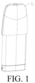
FIG. 1 is a schematic diagram of an overall structure of a vaporizer of the present disclosure; -
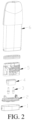
FIG. 2 is an exploded view of a vaporizer of the present disclosure; -
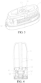
FIG. 3 is a schematic structural diagram of a first liquid guide plate of the present disclosure; -
FIG. 4 is a schematic cross-sectional structural view of a first liquid guide plate of the present disclosure; -
FIG. 5 is a schematic structural diagram of a second liquid guide plate of the present disclosure; -
FIG. 6 is a schematic cross-sectional structural view of a second liquid guide plate of the present disclosure; -
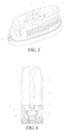
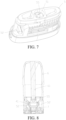
FIG. 7 is a schematic structural diagram of a liquid guide column of the present disclosure; and -
FIG. 8 is a schematic cross-sectional structural view of a liquid guide column of the present disclosure. - In order to have a clearer understanding of the technical features, the objectives, and the effects of the present disclosure, specific implementations of the present disclosure are now illustrated in detail with reference to the accompanying drawings.
- In the following description, it should be understood that orientation or position relationships indicated by the terms such as "front", "rear", "upper", "lower", "left", "right", "longitudinal", "transverse", "vertical", "horizontal", "top", "bottom", "inner", "outer", "head", and "tail" are based on orientation or position relationships shown in the accompanying drawings and structures and operations in specific orientations, and are used only for ease of description of the technical solution, rather than indicating that the mentioned apparatus or element must have a particular orientation. Therefore, such terms should not be construed as a limitation to the present disclosure.
- As shown in
FIG. 1 andFIG. 2 , the present disclosure discloses a vaporizer, which includes a base 2, a vaporization assembly 4 arranged on the base 2, an electrode component 3 running through the base 2 to be electrically connected to the vaporization assembly 4, avaporization base 5 engaged with the vaporization assembly 4, ashell 6 sleeved outside thevaporization base 5 and the base 2, a bottom cap 1 sleeved on the lower side portion and the bottom portion of theshell 6, and an airflow channel. The vaporization assembly 4 includes aporous substrate 41 and a heating body arranged on theporous substrate 41, and thevaporization base 5 supports theporous substrate 41. For example, theporous substrate 41 is a porous ceramic body, and the heating body is a heating film or a heating wire formed on theporous substrate 41 through thin-film printing, thick-film printing, or screen printing, which is not limited thereto. The airflow channel includes an air inlet channel, avaporization cavity 7, and an air outlet channel, where the air outlet channel includes a firstair outlet channel 61 provided on theshell 6 and a secondair outlet channel 52 provided on thevaporization base 5. The vaporizer is configured to heat and vaporize a liquid aerosol-generation substrate to form aerosols, and the aerosols are inhaled to the mouth of a user through the airflow channel. - The vaporizer further includes a liquid guide member, and the liquid guide member is arranged on the end portion of the first
air outlet channel 61 that is close to thevaporization cavity 7. The liquid guide member is configured to be in contact with condensate falling off from the firstair outlet channel 61. The liquid guide member destroys the continuity, namely, surface tension of the condensate through a downward pulling force, and guides the condensate into thevaporization cavity 7. Therefore, secondary vaporization is performed on the condensate during inhalation, and the condensate remained in the vaporizer is reduced. - An
air outlet 51 that is in communication with the bottom portion of the firstair outlet channel 61 and corresponds to the first air outlet channel is further provided on thevaporization base 5, theair outlet 51 is in communication with thevaporization cavity 7, and the liquid guide member is arranged in theair outlet 51. In some embodiments, theair outlet 51 is in communication with thevaporization cavity 7 through the secondair outlet channel 52. - In some embodiments, to further perform secondary vaporization on the condensate, the
air outlet 51 is further in communication with theporous substrate 41, and the liquid guide member guides the condensate into theporous substrate 41 for absorption, so that secondary vaporization is performed on the condensate during inhalation. - As shown in
FIG. 3 and FIG. 4 , in a first embodiment, the liquid guide member includes at least one vertically arrangedliquid guide plate 53. Theliquid guide plate 53 abuts against at least one side of the end portion of the firstair outlet channel 61 that is close to thevaporization cavity 7. - In some embodiments, the
liquid guide plate 53 is arranged in an abutting manner in the circumferential direction of the end portion of the firstair outlet channel 61 that is close to thevaporization cavity 7, and extends for a distance toward the direction of the central axis of the firstair outlet channel 61. Preferably, the liquid guide member includes at least twoliquid guide plates 53 that are arranged opposite to each other. - In some embodiments, the
liquid guide plate 53 crosses two sides of the end portion of the firstair outlet channel 61 that is close to thevaporization cavity 7, and abuts against the two sides of the end portion of the firstair outlet channel 61 that is close to thevaporization cavity 7. That is, a cross section of theliquid guide plate 53 intersects with a cross section of the firstair outlet channel 61. Preferably, theliquid guide plate 53 is arranged on the central axis of the firstair outlet channel 61. - Based on the foregoing embodiments, the liquid guide member may include a plurality of
liquid guide plates 53, and the plurality ofliquid guide plates 53 are spaced. Preferably, the plurality of liquid guide plates are uniformly spaced. It should be noted that, the foregoing embodiments may be randomly combined for use. For example, the embodiment that theliquid guide plate 53 is arranged in an abutting manner in the circumferential direction of the end portion of the firstair outlet channel 61 that is close to thevaporization cavity 7 and extends for a distance toward the central axis of the firstair outlet channel 61 and the embodiment that theliquid guide plate 53 crosses two sides of the end portion of the firstair outlet channel 61 that is close to thevaporization cavity 7 and abuts against the two sides of the end portion of the firstair outlet channel 61 that is close to thevaporization cavity 7 may be combined for use, and the two liquid guide plates are spaced alternately. - As shown in
FIG. 7 and FIG. 8 , in a second embodiment, the liquid guide member includes aliquid guide column 55. Theliquid guide column 55 is arranged in a hollow portion of the end portion of the firstair outlet channel 61 that is close to thevaporization cavity 7. - To destroy the surface tension of the condensate falling off from the first
air outlet channel 61 in time, the end surface of theliquid guide column 55 that is close to the firstair outlet channel 61 is flush with or higher than the end surface of the firstair outlet channel 61 that is close to thevaporization cavity 7. Preferably, theliquid guide column 55 is arranged on the central axis of the firstair outlet channel 61. - In some other embodiments, the liquid guide member may include a
liquid guide column 55 and at least oneliquid guide plate 53 vertically extending outward in the circumferential direction of theliquid guide column 55. Theliquid guide column 55 is arranged in the hollow portion of the end portion of the firstair outlet channel 61 that is close to thevaporization cavity 7, theliquid guide plate 53 abuts against the end portion of the firstair outlet channel 61 that is close to thevaporization cavity 7, and the at least oneliquid guide plate 53 is arranged opposite to each other. - Based on the foregoing embodiments, to destroy the surface tension of the condensate more easily, the end portion of the liquid guide member that is close to the first
air outlet channel 61 is a tip end portion, for example, an inclined surface. - In addition, to better guide the condensate into the
vaporization cavity 7 after the surface tension of the condensate is destroyed, a plurality of liquid guide grooves are further provided on the outer side wall of the liquid guide member. - The present disclosure further discloses an electronic vaporization device, including a power supply device and the vaporizer of any one of the foregoing embodiments.
- As shown in
FIG. 1 andFIG. 2 , the vaporizer includes a base 2, a vaporization assembly 4 arranged on the base 2, an electrode component 3 running through the base 2 to be electrically connected to the vaporization assembly 4, avaporization base 5 engaged with the vaporization assembly 4, ashell 6 sleeved outside thevaporization base 5 and the base 2, a bottom cap 1 sleeved on the lower side portion and the bottom portion of theshell 6, and an airflow channel. The vaporization assembly 4 includes aporous substrate 41 and a heating body arranged on theporous substrate 41, and thevaporization base 5 supports theporous substrate 41. For example, theporous substrate 41 is a porous ceramic body, and the heating body is a heating film or a heating wire formed on theporous substrate 41 through thin-film printing, thick-film printing, or screen printing, which is not limited thereto. The airflow channel includes an air inlet channel, avaporization cavity 7, and an air outlet channel, wherein the air outlet channel includes a firstair outlet channel 61 provided on theshell 6 and a secondair outlet channel 52 provided on thevaporization base 5. The vaporizer is configured to heat and vaporize a liquid aerosol-generation substrate to form aerosols, and the aerosols are inhaled to the mouth of a user through the airflow channel. - The vaporizer further includes a liquid guide member, and the liquid guide member is arranged on the end portion of the first
air outlet channel 61 that is close to thevaporization cavity 7. The liquid guide member is configured to be in contact with condensate falling off from the firstair outlet channel 61. The liquid guide member destroys the continuity, namely, surface tension of the condensate through a downward pulling force, and guides the condensate into thevaporization cavity 7. Therefore, secondary vaporization is performed on the condensate during inhalation, and the condensate remained in the vaporizer is reduced. - An
air outlet 51 that is in communication with the bottom portion of the firstair outlet channel 61 and corresponds to the first air outlet channel is further provided on thevaporization base 5, theair outlet 51 is in communication with thevaporization cavity 7, and the liquid guide member is arranged in theair outlet 51. In some embodiments, theair outlet 51 is in communication with thevaporization cavity 7 through the secondair outlet channel 52. - In some embodiments, to further perform secondary vaporization on the condensate, the
air outlet 51 is further in communication with theporous substrate 41, and the liquid guide member guides the condensate into theporous substrate 41 for absorption, so that secondary vaporization is performed on the condensate during inhalation. - As shown in
FIG. 3 and FIG. 4 , in a first embodiment, the liquid guide member includes at least one vertically arrangedliquid guide plate 53. Theliquid guide plate 53 abuts against at least one side of the end portion of the firstair outlet channel 61 that is close to thevaporization cavity 7. - In some embodiments, the
liquid guide plate 53 is arranged in an abutting manner in the circumferential direction of the end portion of the firstair outlet channel 61 that is close to thevaporization cavity 7, and extends for a distance toward the central axis of the firstair outlet channel 61. Preferably, the liquid guide member includes at least twoliquid guide plates 53 that are arranged opposite to each other. - In some embodiments, the
liquid guide plate 53 crosses two sides of the end portion of the firstair outlet channel 61 that is close to thevaporization cavity 7, and abuts against the two sides of the end portion of the firstair outlet channel 61 that is close to thevaporization cavity 7. That is, a cross section of theliquid guide plate 53 intersects with a cross section of the firstair outlet channel 61. Preferably, theliquid guide plate 53 is arranged on the central axis of the firstair outlet channel 61. - Based on the foregoing embodiments, the liquid guide member may include a plurality of
liquid guide plates 53, and the plurality ofliquid guide plates 53 are spaced. Preferably, the plurality of liquid guide plates are uniformly spaced. It should be noted that, the foregoing embodiments may be randomly combined for use. For example, the embodiment that theliquid guide plate 53 is arranged in an abutting manner in the circumferential direction of the end portion of the firstair outlet channel 61 that is close to thevaporization cavity 7 and extends for a distance toward the central axis of the firstair outlet channel 61 and the embodiment that theliquid guide plate 53 crosses two sides of the end portion of the firstair outlet channel 61 that is close to thevaporization cavity 7 and abuts against the two sides of the end portion of the firstair outlet channel 61 that is close to thevaporization cavity 7 may be combined for use, and the two liquid guide plates are spaced alternately. - As shown in
FIG. 7 and FIG. 8 , in a second embodiment, the liquid guide member includes aliquid guide column 55. Theliquid guide column 55 is arranged in the hollow of the end portion of the firstair outlet channel 61 that is close to thevaporization cavity 7. - To destroy the surface tension of the condensate falling off from the first
air outlet channel 61 in time, the end surface of theliquid guide column 55 that is close to the firstair outlet channel 61 is flush with or higher than the end surface of the firstair outlet channel 61 that is close to thevaporization cavity 7. Preferably, theliquid guide column 55 is arranged on the central axis of the firstair outlet channel 61. - In some other embodiments, the liquid guide member may include a
liquid guide column 55 and at least oneliquid guide plate 53 vertically extending outward in the circumferential direction of theliquid guide column 55. Theliquid guide column 55 is arranged in the hollow of the end portion of the firstair outlet channel 61 that is close to thevaporization cavity 7, theliquid guide plate 53 abuts against the end portion of the firstair outlet channel 61 that is close to thevaporization cavity 7, and the at least oneliquid guide plate 53 is arranged opposite to each other. - Based on the foregoing embodiments, to destroy the surface tension of the condensate more easily, the end portion of the liquid guide member that is close to the first
air outlet channel 61 is a tip end portion, for example, an inclined surface. - In addition, to better guide the condensate into the
vaporization cavity 7 after the surface tension of the condensate is destroyed, a plurality of liquid guide grooves are further provided on the outer side wall of the liquid guide member. - Through implementation of the present disclosure, the following beneficial effects are achieved:
- The vaporizer designed in the present disclosure includes a liquid guide member, and the liquid guide member is arranged on the end portion of the first air outlet channel that is close to the vaporization cavity. The liquid guide member is configured to be in contact with condensate falling off from the first air outlet channel, destroy surface tension of the condensate through a downward pulling force, and guide the condensate into the vaporization cavity. Therefore, generation of condensate is prevented or reduced, and secondary vaporization may also be performed on the condensate falling off from the first air outlet channel, thereby improving the user experience.
- While the invention has been illustrated and described in detail in the drawings and foregoing description, such illustration and description are to be considered illustrative or exemplary and not restrictive. It will be understood that changes and modifications may be made by those of ordinary skill within the scope of the following claims. In particular, the present invention covers further embodiments with any combination of features from different embodiments described above and below. Additionally, statements made herein characterizing the invention refer to an embodiment of the invention and not necessarily all embodiments.
- The terms used in the claims should be construed to have the broadest reasonable interpretation consistent with the foregoing description. For example, the use of the article "a" or "the" in introducing an element should not be interpreted as being exclusive of a plurality of elements. Likewise, the recitation of "or" should be interpreted as being inclusive, such that the recitation of "A or B" is not exclusive of "A and B," unless it is clear from the context or the foregoing description that only one of A and B is intended. Further, the recitation of "at least one of A, B and C" should be interpreted as one or more of a group of elements consisting of A, B and C, and should not be interpreted as requiring at least one of each of the listed elements A, B and C, regardless of whether A, B and C are related as categories or otherwise. Moreover, the recitation of "A, B and/or C" or "at least one of A, B and C" should be interpreted as including any singular entity from the listed elements, e.g., A, any subset from the listed elements, e.g., A and B, or the entire list of elements A, B and C.
Claims (14)
- A vaporizer, comprising:a first air outlet channel (61);a vaporization cavity (7) in communication with the first air outlet channel (61); anda liquid guide member;wherein the liquid guide member is arranged on the end of the first air outlet channel (61) that is close to the vaporization cavity (7);wherein the vaporizer further comprises a vaporization base (5);wherein an air outlet (51) that is in communication with the vaporization cavity (7) and the first air outlet channel (61) is provided on the vaporization base (5); and characterized in thatthe liquid guide member is arranged in the air outlet (51)
- The vaporizer of claim 1, wherein the liquid guide member comprises at least one liquid guide plate (53) that is vertically arranged.
- The vaporizer of claim 2, wherein the at least one liquid guide plate (53) abuts against at least one side of the end of the first air outlet channel (61) that is close to the vaporization cavity (7).
- The vaporizer of claim 3, wherein the at least one liquid guide plate (53) is arranged in an abutting manner in the circumferential direction of the end of the first air outlet channel (61) that is close to the vaporization cavity (7), and extends for a distance toward the central axis of the first air outlet channel (61).
- The vaporizer of claim 3, wherein the at least one liquid guide plate (53) crosses two sides of the end of the first air outlet channel (61) that is close to the vaporization cavity (7), and abuts against the two sides of the end of the first air outlet channel (61) that is close to the vaporization cavity (7).
- The vaporizer of claim 5, wherein the at least one liquid guide plate (53) is arranged on the central axis of the first air outlet channel (61).
- The vaporizer of claim 2, wherein the at least one liquid guide plate (53) comprises a plurality of liquid guide plates (53), and
wherein the plurality of liquid guide plates (53) are spaced. - The vaporizer of claim 1, wherein the liquid guide member comprises a liquid guide column (55).
- The vaporizer of claim 8, wherein the liquid guide column (55) is arranged in the hollow of the end of the first air outlet channel (61) that is close to the vaporization cavity (7).
- The vaporizer of claim 9, wherein the liquid guide column (55) is arranged on the central axis of the first air outlet channel (61).
- The vaporizer of claim 8, wherein the end surface of the liquid guide column (55) that is close to the first air outlet channel (61) is flush with or higher than the end surface of the first air outlet channel (61) that is close to the vaporization cavity (7).
- The vaporizer of any one of claims 1 to 11, wherein the end of the liquid guide member that is close to the first air outlet channel (61) is a tip end.
- The vaporizer of any one of claims 1 to 11, wherein a plurality of liquid guide grooves are provided on the outer side wall of the liquid guide member.
- An electronic vaporization device, characterized by comprising:a power supply device; andthe vaporizer of any one of claims 1 to 13.
Applications Claiming Priority (1)
| Application Number | Priority Date | Filing Date | Title |
|---|---|---|---|
| CN202121545354.6U CN216088897U (en) | 2021-07-07 | 2021-07-07 | Electronic atomization device and atomizer thereof |
Publications (2)
| Publication Number | Publication Date |
|---|---|
| EP4115755A1 EP4115755A1 (en) | 2023-01-11 |
| EP4115755B1 true EP4115755B1 (en) | 2025-02-12 |
Family
ID=80721849
Family Applications (1)
| Application Number | Title | Priority Date | Filing Date |
|---|---|---|---|
| EP22182225.7A Active EP4115755B1 (en) | 2021-07-07 | 2022-06-30 | Electronic vaporization device and vaporizer thereof |
Country Status (5)
| Country | Link |
|---|---|
| US (1) | US20230009024A1 (en) |
| EP (1) | EP4115755B1 (en) |
| JP (1) | JP7449335B2 (en) |
| KR (1) | KR102686661B1 (en) |
| CN (1) | CN216088897U (en) |
Families Citing this family (1)
| Publication number | Priority date | Publication date | Assignee | Title |
|---|---|---|---|---|
| CN217826745U (en) * | 2022-04-02 | 2022-11-18 | 深圳麦克韦尔科技有限公司 | Electronic atomization device and atomizer thereof |
Citations (8)
| Publication number | Priority date | Publication date | Assignee | Title |
|---|---|---|---|---|
| KR20160013342A (en) | 2014-07-24 | 2016-02-04 | 연세대학교 산학협력단 | Nanoparticle comprising hydrophobic drug conjugated to cationic polymer and hydrophilic drug conjugated to anionic polymer |
| CN110584205A (en) | 2019-08-27 | 2019-12-20 | 深圳市云创高科电子有限公司 | Electronic cigarette |
| CN209931491U (en) | 2019-03-14 | 2020-01-14 | 深圳市合元科技有限公司 | Cigarette bullet and electron cigarette |
| WO2020176901A2 (en) | 2019-02-28 | 2020-09-03 | Juul Labs, Inc. | Vaporizer device with vaporizer cartridge |
| WO2021053228A1 (en) | 2019-09-20 | 2021-03-25 | Nerudia Limited | Smoking substitute apparatus |
| WO2021062779A1 (en) | 2019-09-30 | 2021-04-08 | 深圳麦克韦尔科技有限公司 | Electronic vaporization device and vaporizer thereof |
| EP4282287A1 (en) | 2021-01-20 | 2023-11-29 | Shenzhen First Union Technology Co., Ltd. | Atomizer and electronic atomization device |
| EP4285755A1 (en) | 2021-01-27 | 2023-12-06 | Shenzhen First Union Technology Co., Ltd. | Atomizer and electronic atomization device |
Family Cites Families (7)
| Publication number | Priority date | Publication date | Assignee | Title |
|---|---|---|---|---|
| EP2460422A1 (en) * | 2010-12-03 | 2012-06-06 | Philip Morris Products S.A. | An aerosol generating system with provention of condensate leakage |
| KR101316347B1 (en) * | 2012-04-03 | 2013-10-08 | 박선순 | Electronic cigarette |
| WO2016045076A1 (en) * | 2014-09-26 | 2016-03-31 | 深圳麦克韦尔股份有限公司 | Inhaler, atomizing assembly and atomizing core |
| CN210203316U (en) * | 2019-05-07 | 2020-03-31 | 深圳市合元科技有限公司 | Cartridges and Electronic Cigarettes |
| JP7408768B2 (en) * | 2019-09-30 | 2024-01-05 | 深▲せん▼麦克韋爾科技有限公司 | Electronic vaporizer and its vaporizer |
| US20220053827A1 (en) * | 2019-12-04 | 2022-02-24 | Continental Automotive Systems, Inc. | Vaporization device |
| CN111109664B (en) * | 2020-01-15 | 2023-12-26 | 深圳麦克韦尔科技有限公司 | Electronic atomization device and atomizer thereof |
-
2021
- 2021-07-07 CN CN202121545354.6U patent/CN216088897U/en active Active
-
2022
- 2022-06-28 KR KR1020220079259A patent/KR102686661B1/en active Active
- 2022-06-30 EP EP22182225.7A patent/EP4115755B1/en active Active
- 2022-07-05 US US17/857,365 patent/US20230009024A1/en active Pending
- 2022-07-06 JP JP2022108993A patent/JP7449335B2/en active Active
Patent Citations (8)
| Publication number | Priority date | Publication date | Assignee | Title |
|---|---|---|---|---|
| KR20160013342A (en) | 2014-07-24 | 2016-02-04 | 연세대학교 산학협력단 | Nanoparticle comprising hydrophobic drug conjugated to cationic polymer and hydrophilic drug conjugated to anionic polymer |
| WO2020176901A2 (en) | 2019-02-28 | 2020-09-03 | Juul Labs, Inc. | Vaporizer device with vaporizer cartridge |
| CN209931491U (en) | 2019-03-14 | 2020-01-14 | 深圳市合元科技有限公司 | Cigarette bullet and electron cigarette |
| CN110584205A (en) | 2019-08-27 | 2019-12-20 | 深圳市云创高科电子有限公司 | Electronic cigarette |
| WO2021053228A1 (en) | 2019-09-20 | 2021-03-25 | Nerudia Limited | Smoking substitute apparatus |
| WO2021062779A1 (en) | 2019-09-30 | 2021-04-08 | 深圳麦克韦尔科技有限公司 | Electronic vaporization device and vaporizer thereof |
| EP4282287A1 (en) | 2021-01-20 | 2023-11-29 | Shenzhen First Union Technology Co., Ltd. | Atomizer and electronic atomization device |
| EP4285755A1 (en) | 2021-01-27 | 2023-12-06 | Shenzhen First Union Technology Co., Ltd. | Atomizer and electronic atomization device |
Also Published As
| Publication number | Publication date |
|---|---|
| JP2023010654A (en) | 2023-01-20 |
| EP4115755A1 (en) | 2023-01-11 |
| KR102686661B1 (en) | 2024-07-22 |
| JP7449335B2 (en) | 2024-03-13 |
| KR20230008608A (en) | 2023-01-16 |
| US20230009024A1 (en) | 2023-01-12 |
| CN216088897U (en) | 2022-03-22 |
Similar Documents
| Publication | Publication Date | Title |
|---|---|---|
| US20230346035A1 (en) | Vaporizer and electronic vaporization apparatus | |
| CN104661545B (en) | electrical smoking device | |
| EP4458186A1 (en) | Heating assembly, atomizer, and electronic atomizing device | |
| CA2443540A1 (en) | A method of and apparatus for ionizing an analyte and ion source probe for use therewith | |
| KR102771381B1 (en) | Electronic ignition device and ignition device thereof | |
| EP4159057B1 (en) | Heating body, atomizer and electronic atomization device | |
| EP4115755B1 (en) | Electronic vaporization device and vaporizer thereof | |
| US20230380501A1 (en) | Vaporizer and electronic vaporization device | |
| KR20220044285A (en) | Aerosol-generating devices and methods of generating mixed aerosols | |
| US20230320425A1 (en) | Vaporizer and electronic vaporization device | |
| CN217937216U (en) | Atomizing core, atomizer and aerosol generating device | |
| CN219396263U (en) | Electronic atomizing device | |
| WO2024234842A1 (en) | Heating assembly, atomizer, and electronic atomization device | |
| CN214802302U (en) | Host and electronic atomization device | |
| WO2022161015A1 (en) | Atomization core having protective cover | |
| CN217826745U (en) | Electronic atomization device and atomizer thereof | |
| CN216853813U (en) | Host and electronic atomization device | |
| CN219396272U (en) | Electronic atomizing device | |
| CN218790514U (en) | Atomizer and electronic atomization device | |
| CN218185260U (en) | Atomizer and electronic atomization device | |
| US20230087970A1 (en) | Method for manufacturing vaporizer, vaporizer, and electronic vaporization device | |
| CN116135242A (en) | Atomizer | |
| EP4331401A1 (en) | Porous ceramic atomization core and electronic atomization device thereof | |
| CN220360094U (en) | Atomizer and aerosol generating device | |
| CN222776966U (en) | Atomization assembly and electronic atomization device equipped with the same |
Legal Events
| Date | Code | Title | Description |
|---|---|---|---|
| PUAI | Public reference made under article 153(3) epc to a published international application that has entered the european phase |
Free format text: ORIGINAL CODE: 0009012 |
|
| STAA | Information on the status of an ep patent application or granted ep patent |
Free format text: STATUS: THE APPLICATION HAS BEEN PUBLISHED |
|
| AK | Designated contracting states |
Kind code of ref document: A1 Designated state(s): AL AT BE BG CH CY CZ DE DK EE ES FI FR GB GR HR HU IE IS IT LI LT LU LV MC MK MT NL NO PL PT RO RS SE SI SK SM TR |
|
| STAA | Information on the status of an ep patent application or granted ep patent |
Free format text: STATUS: REQUEST FOR EXAMINATION WAS MADE |
|
| 17P | Request for examination filed |
Effective date: 20230628 |
|
| RBV | Designated contracting states (corrected) |
Designated state(s): AL AT BE BG CH CY CZ DE DK EE ES FI FR GB GR HR HU IE IS IT LI LT LU LV MC MK MT NL NO PL PT RO RS SE SI SK SM TR |
|
| RAP3 | Party data changed (applicant data changed or rights of an application transferred) |
Owner name: SHENZHEN SMOORE TECHNOLOGY LIMITED |
|
| GRAP | Despatch of communication of intention to grant a patent |
Free format text: ORIGINAL CODE: EPIDOSNIGR1 |
|
| STAA | Information on the status of an ep patent application or granted ep patent |
Free format text: STATUS: GRANT OF PATENT IS INTENDED |
|
| RIC1 | Information provided on ipc code assigned before grant |
Ipc: A24F 40/10 20200101ALN20241108BHEP Ipc: A24F 40/485 20200101AFI20241108BHEP |
|
| INTG | Intention to grant announced |
Effective date: 20241125 |
|
| GRAS | Grant fee paid |
Free format text: ORIGINAL CODE: EPIDOSNIGR3 |
|
| GRAA | (expected) grant |
Free format text: ORIGINAL CODE: 0009210 |
|
| STAA | Information on the status of an ep patent application or granted ep patent |
Free format text: STATUS: THE PATENT HAS BEEN GRANTED |
|
| P01 | Opt-out of the competence of the unified patent court (upc) registered |
Free format text: CASE NUMBER: APP_67732/2024 Effective date: 20241223 |
|
| AK | Designated contracting states |
Kind code of ref document: B1 Designated state(s): AL AT BE BG CH CY CZ DE DK EE ES FI FR GB GR HR HU IE IS IT LI LT LU LV MC MK MT NL NO PL PT RO RS SE SI SK SM TR |
|
| REG | Reference to a national code |
Ref country code: GB Ref legal event code: FG4D |
|
| REG | Reference to a national code |
Ref country code: CH Ref legal event code: EP |
|
| REG | Reference to a national code |
Ref country code: DE Ref legal event code: R096 Ref document number: 602022010401 Country of ref document: DE |
|
| REG | Reference to a national code |
Ref country code: IE Ref legal event code: FG4D |
|
| RAP4 | Party data changed (patent owner data changed or rights of a patent transferred) |
Owner name: SHENZHEN SMOORE TECHNOLOGY LIMITED |
|
| REG | Reference to a national code |
Ref country code: NL Ref legal event code: MP Effective date: 20250212 |
|
| PG25 | Lapsed in a contracting state [announced via postgrant information from national office to epo] |
Ref country code: RS Free format text: LAPSE BECAUSE OF FAILURE TO SUBMIT A TRANSLATION OF THE DESCRIPTION OR TO PAY THE FEE WITHIN THE PRESCRIBED TIME-LIMIT Effective date: 20250512 |
|
| PG25 | Lapsed in a contracting state [announced via postgrant information from national office to epo] |
Ref country code: FI Free format text: LAPSE BECAUSE OF FAILURE TO SUBMIT A TRANSLATION OF THE DESCRIPTION OR TO PAY THE FEE WITHIN THE PRESCRIBED TIME-LIMIT Effective date: 20250212 |
|
| PG25 | Lapsed in a contracting state [announced via postgrant information from national office to epo] |
Ref country code: PL Free format text: LAPSE BECAUSE OF FAILURE TO SUBMIT A TRANSLATION OF THE DESCRIPTION OR TO PAY THE FEE WITHIN THE PRESCRIBED TIME-LIMIT Effective date: 20250212 |
|
| PGFP | Annual fee paid to national office [announced via postgrant information from national office to epo] |
Ref country code: DE Payment date: 20250617 Year of fee payment: 4 |
|
| PG25 | Lapsed in a contracting state [announced via postgrant information from national office to epo] |
Ref country code: ES Free format text: LAPSE BECAUSE OF FAILURE TO SUBMIT A TRANSLATION OF THE DESCRIPTION OR TO PAY THE FEE WITHIN THE PRESCRIBED TIME-LIMIT Effective date: 20250212 |
|
| REG | Reference to a national code |
Ref country code: LT Ref legal event code: MG9D |
|
| PG25 | Lapsed in a contracting state [announced via postgrant information from national office to epo] |
Ref country code: IS Free format text: LAPSE BECAUSE OF FAILURE TO SUBMIT A TRANSLATION OF THE DESCRIPTION OR TO PAY THE FEE WITHIN THE PRESCRIBED TIME-LIMIT Effective date: 20250612 Ref country code: NO Free format text: LAPSE BECAUSE OF FAILURE TO SUBMIT A TRANSLATION OF THE DESCRIPTION OR TO PAY THE FEE WITHIN THE PRESCRIBED TIME-LIMIT Effective date: 20250512 |
|
| PG25 | Lapsed in a contracting state [announced via postgrant information from national office to epo] |
Ref country code: NL Free format text: LAPSE BECAUSE OF FAILURE TO SUBMIT A TRANSLATION OF THE DESCRIPTION OR TO PAY THE FEE WITHIN THE PRESCRIBED TIME-LIMIT Effective date: 20250212 |
|
| PG25 | Lapsed in a contracting state [announced via postgrant information from national office to epo] |
Ref country code: HR Free format text: LAPSE BECAUSE OF FAILURE TO SUBMIT A TRANSLATION OF THE DESCRIPTION OR TO PAY THE FEE WITHIN THE PRESCRIBED TIME-LIMIT Effective date: 20250212 |
|
| PG25 | Lapsed in a contracting state [announced via postgrant information from national office to epo] |
Ref country code: PT Free format text: LAPSE BECAUSE OF FAILURE TO SUBMIT A TRANSLATION OF THE DESCRIPTION OR TO PAY THE FEE WITHIN THE PRESCRIBED TIME-LIMIT Effective date: 20250612 Ref country code: LV Free format text: LAPSE BECAUSE OF FAILURE TO SUBMIT A TRANSLATION OF THE DESCRIPTION OR TO PAY THE FEE WITHIN THE PRESCRIBED TIME-LIMIT Effective date: 20250212 |
|
| PGFP | Annual fee paid to national office [announced via postgrant information from national office to epo] |
Ref country code: FR Payment date: 20250630 Year of fee payment: 4 |
|
| PG25 | Lapsed in a contracting state [announced via postgrant information from national office to epo] |
Ref country code: GR Free format text: LAPSE BECAUSE OF FAILURE TO SUBMIT A TRANSLATION OF THE DESCRIPTION OR TO PAY THE FEE WITHIN THE PRESCRIBED TIME-LIMIT Effective date: 20250513 Ref country code: BG Free format text: LAPSE BECAUSE OF FAILURE TO SUBMIT A TRANSLATION OF THE DESCRIPTION OR TO PAY THE FEE WITHIN THE PRESCRIBED TIME-LIMIT Effective date: 20250212 |
|
| REG | Reference to a national code |
Ref country code: AT Ref legal event code: MK05 Ref document number: 1765173 Country of ref document: AT Kind code of ref document: T Effective date: 20250212 |
|
| PG25 | Lapsed in a contracting state [announced via postgrant information from national office to epo] |
Ref country code: SE Free format text: LAPSE BECAUSE OF FAILURE TO SUBMIT A TRANSLATION OF THE DESCRIPTION OR TO PAY THE FEE WITHIN THE PRESCRIBED TIME-LIMIT Effective date: 20250212 |
|
| PG25 | Lapsed in a contracting state [announced via postgrant information from national office to epo] |
Ref country code: SM Free format text: LAPSE BECAUSE OF FAILURE TO SUBMIT A TRANSLATION OF THE DESCRIPTION OR TO PAY THE FEE WITHIN THE PRESCRIBED TIME-LIMIT Effective date: 20250212 |
|
| PG25 | Lapsed in a contracting state [announced via postgrant information from national office to epo] |
Ref country code: DK Free format text: LAPSE BECAUSE OF FAILURE TO SUBMIT A TRANSLATION OF THE DESCRIPTION OR TO PAY THE FEE WITHIN THE PRESCRIBED TIME-LIMIT Effective date: 20250212 |
|
| PG25 | Lapsed in a contracting state [announced via postgrant information from national office to epo] |
Ref country code: IT Free format text: LAPSE BECAUSE OF FAILURE TO SUBMIT A TRANSLATION OF THE DESCRIPTION OR TO PAY THE FEE WITHIN THE PRESCRIBED TIME-LIMIT Effective date: 20250212 |
|
| PG25 | Lapsed in a contracting state [announced via postgrant information from national office to epo] |
Ref country code: AT Free format text: LAPSE BECAUSE OF FAILURE TO SUBMIT A TRANSLATION OF THE DESCRIPTION OR TO PAY THE FEE WITHIN THE PRESCRIBED TIME-LIMIT Effective date: 20250212 |
|
| PG25 | Lapsed in a contracting state [announced via postgrant information from national office to epo] |
Ref country code: EE Free format text: LAPSE BECAUSE OF FAILURE TO SUBMIT A TRANSLATION OF THE DESCRIPTION OR TO PAY THE FEE WITHIN THE PRESCRIBED TIME-LIMIT Effective date: 20250212 Ref country code: CZ Free format text: LAPSE BECAUSE OF FAILURE TO SUBMIT A TRANSLATION OF THE DESCRIPTION OR TO PAY THE FEE WITHIN THE PRESCRIBED TIME-LIMIT Effective date: 20250212 |
|
| PG25 | Lapsed in a contracting state [announced via postgrant information from national office to epo] |
Ref country code: RO Free format text: LAPSE BECAUSE OF FAILURE TO SUBMIT A TRANSLATION OF THE DESCRIPTION OR TO PAY THE FEE WITHIN THE PRESCRIBED TIME-LIMIT Effective date: 20250212 |
|
| PG25 | Lapsed in a contracting state [announced via postgrant information from national office to epo] |
Ref country code: SK Free format text: LAPSE BECAUSE OF FAILURE TO SUBMIT A TRANSLATION OF THE DESCRIPTION OR TO PAY THE FEE WITHIN THE PRESCRIBED TIME-LIMIT Effective date: 20250212 |
|
| REG | Reference to a national code |
Ref country code: DE Ref legal event code: R026 Ref document number: 602022010401 Country of ref document: DE |
|
| PLBI | Opposition filed |
Free format text: ORIGINAL CODE: 0009260 |
|
| PLAX | Notice of opposition and request to file observation + time limit sent |
Free format text: ORIGINAL CODE: EPIDOSNOBS2 |
|
| 26 | Opposition filed |
Opponent name: MURGITROYD & COMPANY LIMITED Effective date: 20251110 |