EP4115725A1 - Mower - Google Patents
Mower Download PDFInfo
- Publication number
- EP4115725A1 EP4115725A1 EP22177034.0A EP22177034A EP4115725A1 EP 4115725 A1 EP4115725 A1 EP 4115725A1 EP 22177034 A EP22177034 A EP 22177034A EP 4115725 A1 EP4115725 A1 EP 4115725A1
- Authority
- EP
- European Patent Office
- Prior art keywords
- grass
- receiver
- mown
- mower
- collector
- Prior art date
- Legal status (The legal status is an assumption and is not a legal conclusion. Google has not performed a legal analysis and makes no representation as to the accuracy of the status listed.)
- Granted
Links
Images


Classifications
-
- A—HUMAN NECESSITIES
- A01—AGRICULTURE; FORESTRY; ANIMAL HUSBANDRY; HUNTING; TRAPPING; FISHING
- A01D—HARVESTING; MOWING
- A01D43/00—Mowers combined with apparatus performing additional operations while mowing
- A01D43/06—Mowers combined with apparatus performing additional operations while mowing with means for collecting, gathering or loading mown material
- A01D43/063—Mowers combined with apparatus performing additional operations while mowing with means for collecting, gathering or loading mown material in or into a container carried by the mower; Containers therefor
- A01D43/0631—Control devices specially adapted therefor
Definitions
- the present invention relates to a mower.
- Japanese Unexamined Patent Application Publication, Tokukai, No. 2006-246804 discloses a mower including a mower unit, a grass collector, and a guide duct configured to guide grass mown by the mower unit to the grass collector.
- the grass collector includes a front wall with which the guide duct is connected and a fullness detector at a lower portion of the front wall.
- the fullness detector is configured to detect in response to being pressed by mown grass in the grass collector that the grass collector has become full of mown grass.
- the present invention has an object of providing a mower including a fullness detector with an easily adjustable detection sensitivity.
- a mower according to the present invention includes:
- the present invention is configured as follows: In response to the grass collector becoming full of mown grass, the receiver of the fullness detector is pressed by the mown grass against the urging force of the urging member. The detection sensor then detects that the receiver has been pressed by the mown grass. The fullness detector thus detects that the grass collector has become full.
- the fullness detector for the present invention includes a weight attached to the receiver and having a moment for swinging the receiver. With the receiver configured, for instance, to be pressed downward by mown grass against the urging force of the urging member, the weight applies its moment load in such a direction as to decrease the urging force.
- the weight applies its moment load in such a direction as to increase the urging force.
- the present invention is configured such that the weight is attached to the receiver in such a manner as to be movable in the direction in which the receiver extends. Moving the weight to adjust the length of the moment arm (that is, the distance between the axis of the receiver and the weight) changes the level of the moment of the weight for swinging the receiver. With this configuration, adjusting the level of the moment of the weight to decrease the urging force of the urging member allows the receiver to be swung even in response to weak press by mown grass and the detection sensor to detect that the receiver has been pressed.
- the fullness detector in this case, has a high detection sensitivity (sensitive). In contrast, adjusting the level of the moment of the weight to increase the urging force of the urging member allows the receiver to be swung only in response to strong press by mown grass.
- the fullness detector in this case, has a low detection sensitivity (insensitive). With the present invention, simply moving the weight on the receiver to a different position allows the detection sensitivity of the fullness detector to be easily adjusted in accordance with various states such as the state of the work area for a mowing operation.
- the mower is further arranged such that the weight is attached to a first face of the receiver which first face is opposite to a second face of the receiver which second face is configured to be pressed toward the first side by the mown grass in contact with the receiver.
- the above configuration prevents mown grass from easily coming into contact with the weight when pressing the receiver. This reduces the possibility of mown grass being caught by the weight and hindering the swing of the receiver. This in turn allows the fullness detector to operate more stably.
- the mower further includes: a position change operation tool manually operable to fix and unfix the weight and to move the weight in the extension direction of the receiver.
- the above configuration allows the operator to use the position change operation tool to unfix, move, and fix the weight on the receiver. This allows the operator to perform these operations conveniently.
- the mower is further arranged such that
- the mown grass in the grass collector may accumulate unevenly, depending on, for example, the kind of grass in the work area or whether the grass is wet.
- the grass collector has become full (or almost full)
- the mown grass blocks an inlet portion of the grass collector with which the guide duct is connected. This prevents mown grass from the mower unit from entering the grass collector.
- mow grass in this state leads to mown grass from the mower unit starting to accumulate on the bottom of that portion of the guide duct which is connected with the grass collector. The accumulation of mown grass on the bottom of the guide duct then grows toward the mower unit.
- the above mower is configured to determine in response to mown grass blocking the inlet portion of the grass collector that the grass collector has become full.
- the receiver is configured to be pressed downward by mown grass in an appropriate manner. This allows the fullness detector to operate stably.
- the mower is further arranged such that
- the accumulation of mown grass from the mower unit may grow from the bottom of the inlet portion toward the mower unit on the bottom portion of the guide duct.
- the fullness detector includes a receiver extending from its axis toward the grass collector, the far end of the receiver may catch mown grass as its accumulation grows on the bottom portion of the guide duct toward the mower unit and thereby prevent the mown grass from coming onto the receiver. This may cause the receiver to fail to be pressed downward by the mown grass.
- the above mower is configured such that the receiver of the fullness detector extends from its axis toward the side opposite to the grass collector. This allows the accumulation of mown grass to grow easily from the position of the axis of the receiver onto its upper face as it grows on the bottom portion of the guide duct toward the mower unit. This in turn allows the fullness detector to operate stably.
- the mower is further arranged such that
- the fullness detector includes a receiver extending from its axis toward the side opposite to the grass collector as described above, mown grass from the mower unit may be caught by the far end of the receiver when guided through the guide duct into the grass collector.
- the guide duct has a bottom portion with an area from the second bottom surface portion to the third bottom surface portion which area is below the first bottom surface portion as viewed from the mower unit toward the grass collector through the guide duct.
- the second bottom surface portion will temporarily hold the forward growth of the accumulation of mown grass.
- the operator can stop the mowing operation during that time period to prevent the accumulation of mown grass from growing further forward to reach the mower unit.
- Figs. 1 to 5 illustrate a riding-type mower.
- Figs. 1 to 5 show arrow F to indicate the forward direction, arrow B to indicate the backward direction, arrow U to indicate the upward direction, arrow D to indicate the downward direction, arrow L to indicate the leftward direction, and arrow R to indicate the rightward direction.
- the mower includes left and right front wheels 1, left and right rear wheels 2, a body 3 supported by the front wheels 1 and the rear wheels 2 in such a manner as to be capable of traveling, a steering wheel 4 disposed on the body 3 for use to turn the front wheels 1, a driver's seat 5 on the body 3, an engine 6 at a front portion of the body 3, and a ROPS frame 7 at a back portion of the body 3.
- the mower includes a mower unit 8 and a link mechanism 9.
- the mower unit 8 is disposed between the front wheels 1 and the rear wheels 2, and is suspended from the body 3 with use of the link mechanism 9.
- the mower unit 8 includes blades 8a arranged in the left-right direction and each drivable to rotate about an axis extending in the up-down direction.
- the mower also includes a grass collector 10 and a guide duct 11.
- the grass collector 10 is supported by a back portion of the body 3 and capable of storing mown grass.
- the guide duct 11 extends from the mower unit 8 to the grass collector 10.
- the above configuration allows the mower to operate as follows: As the body 3 travels forward, the mower unit 8 mows grass with use of its blades 8a. The rotation of the blades 8a produces a conveyance wind, which guides the mown grass through the guide duct 11 into the grass collector 10 for storage.
- the grass collector 10 includes a plate-shaped front wall 12 and a box-shaped grass container 13.
- the front wall 12 is coupled to a back portion of the body 3, and has a width equivalent to the distance between the rear wheels 2.
- the front wall 12 has an opening 12a.
- the guide duct 11 has a dimension in the up-down direction which dimension extends from the upper end of the front wall 12 to its lower end, and extends from a central portion in the left-right direction of a back portion of the mower unit 8 to the opening 12a.
- the grass container 13 includes (i) a box-shaped frame, (ii) permeable members such as perforated metal plates or meshes attached to the bottom, back, and lateral sides of the frame, and (iii) a non-permeable top plate attached to the top of the frame.
- the frame is open on its front.
- the grass container 13 has a front portion with upper left and upper right portions held respectively by upper left and upper right portions of the front wall 12 in such a manner as to be swingable about an axis P1 extending in the left-right direction.
- the mower includes a lifting/lowering cylinder 14 connected with the front wall 12 and the grass container 13 and configured to lift and lower the grass container 13 about the axis P1.
- Fig. 1 illustrates the grass container 13 having been lowered with use of the lifting/lowering cylinder 14 into a working state.
- the front wall 12 has a lower portion provided with left and right lock members 15.
- the lock members 15 in Fig. 1 are engaged with the grass container 13, so that the grass container 13 is fixed in its working state.
- the grass container 13 in its working state has a front portion connected with the front wall 12, so that the grass container 13 has a front portion closed by the front wall 12.
- the mower is configured as described above to, with the grass container 13 in its working state, guide grass mown by the mower unit 8 through the guide duct 11 and the opening 12a in the front wall 12 into the grass collector 10 (which includes the front wall 12 and the grass container 13) for storage.
- the operator stops the mowing operation in response to the grass collector 10 becoming full.
- the operator then, as indicated in Fig. 2 , unlocks the lock members 15 and lifts the grass container 13 with use of the lifting/lowering cylinder 14 to let the grass container 13 discharge mown grass on its front side onto the ground.
- the description below deals with how the guide duct 11 is configured.
- the guide duct 11 is in the shape of a pipe with a rectangular cross section, and as illustrated in Fig. 1 , includes a top portion 16, left and right lateral portions 17, and a bottom portion 18.
- the top portion 16 is in the shape of a plate, and is connected with the mower unit 8 and that portion of the front wall 12 which forms the upper end of the opening 12a.
- the lateral portions 17 are each in the shape of a plate connected with the mower unit 8, and are connected with those portions of the front wall 12 which respectively form the left and right ends of the opening 12a.
- the bottom portion 18 is in the shape of a bent plate, and includes a first bottom surface portion 18a, a second bottom surface portion 18b, and a third bottom surface portion 18c.
- the first bottom surface portion 18a is connected with the mower unit 8, and extends therefrom obliquely in an upward and backward direction.
- the second bottom surface portion 18b extends downward from the back end of the first bottom surface portion 18a (that is, the end thereof toward the grass collector 10).
- the third bottom surface portion 18c extends from the lower end of the second bottom surface portion 18b obliquely in an upward and backward direction toward the grass collector 10, and is connected with that portion of the front wall 12 which forms the lower end of the opening 12a.
- the third bottom surface portion 18c has a rectangular opening 18d.
- the bottom portion 18 is provided with left and right frame members 19 extending in the longitudinal direction of the guide duct 11 (that is, the front-back direction) and coupled to those portions of the lower surface of the bottom portion 18 which are respectively to the left and right of the opening 18d.
- the third bottom surface portion 18c is provided with a fullness detector 20 configured to detect that the grass collector 10 has become full of mown grass.
- the fullness detector 20 includes a receiver 21, a spring 22 (which corresponds to the "urging member"), a weight 23, a detection sensor 24, a bolt 25 (which corresponds to the "position change operation tool”), and a butterfly nut 26 (which corresponds to the "position change operation tool”).
- the receiver 21 is in the shape of a plate with an edge bent downward, and includes an upper face portion 21a, left and right side face portions 21b, and a front face portion 21c.
- the upper face portion 21a has a slit 21d along the longitudinal direction of the guide duct 11 (that is, the front-back direction).
- the frame members 19 support a pivot shaft 27 extending in the left-right direction under a back portion of the opening 18d (that is, a portion thereof toward the grass collector 10).
- the receiver 21 is at the opening 18d.
- the side face portions 21b have respective back portions (that is, portions thereof toward the grass collector 10) held by the pivot shaft 27 in such a manner that the receiver 21 is swingable in the up-down direction.
- the receiver 21 is held by the pivot shaft 27 in such a manner as to be swingable in the up-down direction about the axis P2 of the pivot shaft 27.
- the receiver 21 extends forward away from the axis P2; in other words, it extends from the axis P2 in the forward direction, which is opposite to the direction toward the grass collector 10.
- the forward direction is a non-limiting example of the "extension direction" according to the present invention.
- the axis P2 (pivot shaft 27) extends in the horizontal, left-right direction; in other words, it extends in the left-right direction, which is orthogonal to the direction in which the guide duct 11 extends (that is, the front-back direction).
- the spring 22 is in the shape of a coil attached to the pivot shaft 27, and urges the receiver 21 upward (that is, toward the side opposite to the side toward which mown grass presses the receiver 21).
- the upward direction is a non-limiting example of the "second side” according to the present invention.
- the side face portions 21b have respective front portions (that is, portions thereof toward the mower unit 8) provided with respective engagement sections 21e protruding forward.
- the receiver 21 is urged upward by the spring 22. This causes the engagement sections 21e to engage with those respective portions of the bottom portion 18 which are forward of the opening 18d (that is, those portions thereof toward the mower unit 8), so that the receiver 21 is locked at a lifted position illustrated in Fig. 4 .
- the upper face portion 21a is above the third bottom surface portion 18c, and the side face portions 21b and the front face portion 21c have respective lower end portions below the third bottom surface portion 18c.
- Figs. 4 and 5 illustrate the following:
- the left frame member 19 is provided with a bracket 28 coupled thereto.
- the detection sensor 24, which includes a limit switch, is attached to the bracket 28.
- the left side face portion 21b has a lower end portion provided with an operation section 21f extending therefrom outward to the right. With the receiver 21 at the lifted position, the detection sensor 24 has a contact section 24a in contact with the lower face of the operation section 21f.
- the operation section 21f presses the contact section 24a downward, in other words, the detection sensor 24 detects that the receiver 21 has been pressed downward from the lifted position.
- the downward direction is a non-limiting example of the "first side" according to the present invention.
- the detection sensor 24 detecting that the receiver 21 has been pressed downward from the lifted position indicates the fullness detector 20 detecting that the grass collector 10 has become full.
- the weight 23 is in the shape of a plate, and is attached to the lower face of the upper face portion 21a of the receiver 21 (that is, the face thereof opposite to that face of the receiver 21 which is pressed by mown grass).
- the face of the upper face portion 21a which is pressed by mown grass is a non-limiting example of the "first face” according to the present invention.
- the lower face of the upper face portion 21a is a non-limiting example of the "second face” according to the present invention.
- the bolt 25 is inserted upward in and coupled to the weight 23.
- the bolt 25 extends through the slit 21d and protrudes upward from the upper face portion 21a.
- the bolt 25 has an upper portion provided with the butterfly nut 26 attached thereto.
- Screwing on the butterfly nut 26 fixes the weight 23 to the receiver 21. Unscrewing the butterfly nut 26 and moving the weight 23 and the bolt 25 along the slit 21d moves the weight 23 in the direction in which the receiver 21 extends (that is, the front-back direction).
- the spring 22 urges the receiver 21 upward about the axis P2.
- the weight 23 has a moment based on the moment arm (that is, the distance between the axis P2 and the weight 23).
- the weight 23 applies its moment load in such a direction as to swing the receiver 21 downward, that is, in such a direction as to decrease the urging force of the spring 22.
- Figs. 4 and 5 each illustrate the weight 23 fixed at the position closest possible to the axis P2.
- the moment arm that is, the distance between the axis P2 and the weight 23
- the weight 23 has the smallest moment and that the spring 22 exerts the largest urging force.
- the receiver 21, in the above state, will not be swung downward from the lifted position unless it is pressed strongly by mown grass.
- the receiver 21 thus has a low swing sensitivity (insensitive).
- the fullness detector 20 has a low detection sensitivity (insensitive).
- the operator can slide the weight 23 forward along the slit 21d from the position illustrated in Figs. 4 and 5 to the position farthest possible away from the axis P2, and then fix the weight 23 with use of the butterfly nut 26.
- the moment arm that is, the distance between the axis P2 and the weight 23
- the weight 23 has the largest moment and that the spring 22 exerts the smallest urging force.
- the receiver 21 With the weight 23 fixed at the position farthest possible away from the axis P2, the receiver 21 will be swung downward from the lifted position even in response to weak press by mown grass.
- the receiver 21 thus has a high swing sensitivity (sensitive).
- the fullness detector 20 has a high detection sensitivity (sensitive).
- moving the weight 23 in the direction in which the receiver 21 extends to adjust the length of the moment arm changes the level of the moment for swinging the receiver 21.
- moving the weight 23 in the direction in which the receiver 21 extends changes the swing sensitivity of the receiver 21 and the detection sensitivity of the fullness detector 20.
- the fullness detector 20 is on the third bottom surface portion 18c.
- the fullness detector 20 is thus behind the first bottom surface portion 18a as viewed from the mower unit 8 toward the grass collector 10 through the guide duct 11.
- the above configuration reduces the possibility of the front face portion 21c of the receiver 21 catching mown grass being guided from the mower unit 8 through the guide duct 11 toward the grass collector 10.
- the opening 12a being blocked by mown grass as mentioned above prevents mown grass from the mower unit 8 from entering the grass collector 10.
- mown grass from the mower unit 8 starting to accumulate on a portion of the bottom portion 18 (specifically, the third bottom surface portion 18c) which portion is connected with the front wall 12.
- the accumulation of mown grass on the bottom portion 18 then grows forward toward the mower unit 8.
- the receiver 21 extends forward away from the axis P2.
- the operation section 21f of the receiver 21 presses the contact section 24a of the detection sensor 24 downward, in other words, the detection sensor 24 detects that the receiver 21 has been pressed downward from the lifted position.
- the fullness detector 20 detects, in response to the detection sensor 24 detecting that the receiver 21 has been pressed downward from the lifted position, that the grass collector 10 has become full.
- the detection by the detection sensor 24 triggers an alarm (not indicated in the drawings) such as a buzzing sound and/or turns on a warning lamp (not indicated in the drawings)
- the operator may move the weight 23 in the direction in which the receiver 21 extends to adjust the moment for swinging the receiver 21 and adjust the swing sensitivity of the receiver 21 and the detection sensitivity of the fullness detector 20.
- the operator stops the mowing operation, and lifts the grass container 13 as illustrated in Fig. 2 to let the grass container 13 discharge mown grass on its front side onto the ground.
- the second bottom surface portion 18b of the bottom portion 18 will temporarily hold the forward growth of the accumulation of mown grass in the guide duct 11 as illustrated in Figs. 3 and 4 .
- the operator can stop the mowing operation during that time period to prevent the accumulation of mown grass from growing further forward to reach the mower unit 8.
- the fullness detector 20 may be disposed at the top portion 16 of the guide duct 11. With the fullness detector 20 configured as such, the receiver 21 protrudes downward from the top portion 16 and is urged by the spring 22 downward.
- the detection sensor 24 is configured to detect that the receiver 21 has been pressed upward by mown grass, so that the fullness detector 20 detects that the grass collector 10 has become full.
- the spring 22 urges the receiver 21 downward about the axis P2.
- the weight 23 has a moment based on the moment arm (that is, the distance between the axis P2 and the weight 23). The weight 23 applies its moment load to cause the receiver 21 to swing downward, that is, in such a direction as to increase the urging force of the spring 22.
- the receiver 21 has a high swing sensitivity (sensitive)
- the fullness detector 20 has a high detection sensitivity (sensitive).
- the receiver 21 has a low swing sensitivity (insensitive), and the fullness detector 20 has a low detection sensitivity (insensitive).
- the receiver 21 may extend away from the axis P2 toward the grass collector 10.
- the receiver 21 configured as such may have a back face portion extending from the back end of the upper face portion 21a obliquely in a downward and backward direction.
- the receiver 21 may extend away from the axis P2 toward the grass collector 10.
- the receiver 21 configured as such may have a back face portion extending from the back end of the lower face portion of the receiver 21 obliquely in a upward and backward direction.
- the axis P2 may extend in the horizontal, front-back direction (that is, the direction in which the guide duct 11 extends).
- the receiver 21 configured as such may have a side face portion 21b on the side toward the grass collector 10 which side face portion 21b extends from the corresponding lateral end of the upper face portion 21a obliquely in a downward and backward direction.
- the axis P2 may extend in the horizontal, front-back direction (that is, the direction in which the guide duct 11 extends).
- the receiver 21 configured as such may have a side face portion 21b on the side toward the grass collector 10 which side face portion 21b extends from the corresponding lateral end of the lower face portion of the receiver 21 obliquely in an upward and backward direction.
- the spring 22 as the urging member may be in the shape of a plate spring instead of a coil.
- the fullness detector 20 may be disposed at a bottom or top portion of the grass collector 10 (specifically, the grass container 13).
- the present invention is applicable not only to a mower including a mower unit 8 between front wheels 1 and rear wheels 2, but also to a mower including a mower unit 8 forward of front wheels 1 and also including a guide duct 11 extending backward from a left or right side portion of the mower unit 8.
Landscapes
- Life Sciences & Earth Sciences (AREA)
- Environmental Sciences (AREA)
- Harvester Elements (AREA)
Abstract
Description
- This application claims the benefit of priority to
Japanese Patent Applications No. 2021-112776 filed on July 7, 2021 - The present invention relates to a mower.
-
Japanese Unexamined Patent Application Publication, Tokukai, No. 2006-246804 - A mower according to the present invention includes:
- a mower unit;
- a grass collector configured to store mown grass;
- a guide duct extending from the mower unit to the grass collector and configured to guide grass mown by the mower unit to the grass collector; and
- a fullness detector configured to detect that the grass collector has become full of mown grass,
- the fullness detector including:
- a receiver swingable in an up-down direction about a horizontal axis, extending in an extension direction away from the axis, and configured to be pressed toward a first side by mown grass in contact with the receiver;
- an urging member urging the receiver toward a second side opposite to the first side;
- a weight attached to the receiver and movable in the extension direction of the receiver toward or away from the axis to adjust a swing sensitivity of the receiver to a press by mown grass; and
- a detection sensor configured to detect that the receiver has been pressed by mown grass.
- The present invention is configured as follows: In response to the grass collector becoming full of mown grass, the receiver of the fullness detector is pressed by the mown grass against the urging force of the urging member. The detection sensor then detects that the receiver has been pressed by the mown grass. The fullness detector thus detects that the grass collector has become full. The fullness detector for the present invention includes a weight attached to the receiver and having a moment for swinging the receiver. With the receiver configured, for instance, to be pressed downward by mown grass against the urging force of the urging member, the weight applies its moment load in such a direction as to decrease the urging force. With the receiver configured, for instance, to be pressed upward by mown grass against the urging force of the urging member, the weight applies its moment load in such a direction as to increase the urging force. The present invention is configured such that the weight is attached to the receiver in such a manner as to be movable in the direction in which the receiver extends. Moving the weight to adjust the length of the moment arm (that is, the distance between the axis of the receiver and the weight) changes the level of the moment of the weight for swinging the receiver. With this configuration, adjusting the level of the moment of the weight to decrease the urging force of the urging member allows the receiver to be swung even in response to weak press by mown grass and the detection sensor to detect that the receiver has been pressed. The fullness detector, in this case, has a high detection sensitivity (sensitive). In contrast, adjusting the level of the moment of the weight to increase the urging force of the urging member allows the receiver to be swung only in response to strong press by mown grass. The fullness detector, in this case, has a low detection sensitivity (insensitive). With the present invention, simply moving the weight on the receiver to a different position allows the detection sensitivity of the fullness detector to be easily adjusted in accordance with various states such as the state of the work area for a mowing operation.
- In one preferred embodiment of the present invention, the mower is further arranged such that
the weight is attached to a first face of the receiver which first face is opposite to a second face of the receiver which second face is configured to be pressed toward the first side by the mown grass in contact with the receiver. - The above configuration prevents mown grass from easily coming into contact with the weight when pressing the receiver. This reduces the possibility of mown grass being caught by the weight and hindering the swing of the receiver. This in turn allows the fullness detector to operate more stably.
- In one preferred embodiment of the present invention, the mower further includes:
a position change operation tool manually operable to fix and unfix the weight and to move the weight in the extension direction of the receiver. - The above configuration allows the operator to use the position change operation tool to unfix, move, and fix the weight on the receiver. This allows the operator to perform these operations conveniently.
- In one preferred embodiment of the present invention, the mower is further arranged such that
- the fullness detector is provided for a bottom portion of the guide duct, and
- the detection sensor is configured to detect that the receiver has been pressed downward by mown grass.
- With a mower configured such that mown grass from a mower unit is guided through a guide duct into a grass collector, the mown grass in the grass collector may accumulate unevenly, depending on, for example, the kind of grass in the work area or whether the grass is wet. When the grass collector has become full (or almost full), the mown grass blocks an inlet portion of the grass collector with which the guide duct is connected. This prevents mown grass from the mower unit from entering the grass collector. Continuing to mow grass in this state leads to mown grass from the mower unit starting to accumulate on the bottom of that portion of the guide duct which is connected with the grass collector. The accumulation of mown grass on the bottom of the guide duct then grows toward the mower unit. Assuming that a fullness detector is on the grass collector under the above circumstances. In such a case, even if the grass collector has actually become full of mown grass, its uneven accumulation may leave the receiver of the fullness detector unpressed by the mown grass and lead to the fullness detector failing to detect that the grass collector has become full. In response to mown grass blocking the inlet portion of the grass collector, the accumulation of mown grass from the mower unit grows from the bottom of the inlet portion of the grass collector toward the mower unit on the bottom portion of the guide duct. With this in view, the above mower is configured to determine in response to mown grass blocking the inlet portion of the grass collector that the grass collector has become full. With the fullness detector on the bottom portion of the guide duct, the receiver is configured to be pressed downward by mown grass in an appropriate manner. This allows the fullness detector to operate stably.
- In one preferred embodiment of the present invention, the mower is further arranged such that
- the axis is orthogonal to a direction in which the guide duct extends, and
- the receiver extends away from the axis toward a side opposite to the grass collector.
- As described above, in response to mown grass blocking the inlet portion of the grass collector with which the guide duct is connected, the accumulation of mown grass from the mower unit may grow from the bottom of the inlet portion toward the mower unit on the bottom portion of the guide duct. In such a case, if the fullness detector includes a receiver extending from its axis toward the grass collector, the far end of the receiver may catch mown grass as its accumulation grows on the bottom portion of the guide duct toward the mower unit and thereby prevent the mown grass from coming onto the receiver. This may cause the receiver to fail to be pressed downward by the mown grass. With this in view, the above mower is configured such that the receiver of the fullness detector extends from its axis toward the side opposite to the grass collector. This allows the accumulation of mown grass to grow easily from the position of the axis of the receiver onto its upper face as it grows on the bottom portion of the guide duct toward the mower unit. This in turn allows the fullness detector to operate stably.
- In one preferred embodiment of the present invention, the mower is further arranged such that
- the bottom portion includes:
- a first bottom surface portion with an end on a side toward the grass collector;
- a second bottom surface portion extending downward from the end of the first bottom surface portion; and
- a third bottom surface portion extending from a lower portion of the second bottom surface portion toward the grass collector, and
- the fullness detector is provided for the third bottom surface portion.
- If the fullness detector includes a receiver extending from its axis toward the side opposite to the grass collector as described above, mown grass from the mower unit may be caught by the far end of the receiver when guided through the guide duct into the grass collector. With the above configuration, the guide duct has a bottom portion with an area from the second bottom surface portion to the third bottom surface portion which area is below the first bottom surface portion as viewed from the mower unit toward the grass collector through the guide duct. Providing the fullness detector for the third bottom surface portion thus allows the fullness detector to be hidden behind the first bottom surface portion. This reduces the possibility of the far end of the receiver catching mown grass being guided from the mower unit through the guide duct toward the grass collector. This in turn allows the fullness detector to operate stably. Even if the operator did not stop the mowing operation in a timely manner after the fullness detector detected that the grass collector has become full, the second bottom surface portion will temporarily hold the forward growth of the accumulation of mown grass. The operator can stop the mowing operation during that time period to prevent the accumulation of mown grass from growing further forward to reach the mower unit.
- The above and other elements, features, steps, characteristics and advantages of the present invention will become more apparent from the following detailed description of the preferred embodiments with reference to the attached drawings.
- Embodiments of the invention will now be described with reference to the accompanying drawings in which:
-
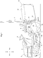
Fig. 1 is a left side view of a mower, -
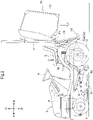
Fig. 2 is a left side view of a mower with a grass collecting container lifted, -
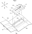
Fig. 3 is an exploded perspective view of a guide duct with a bottom portion and a fullness detector, -
Fig. 4 is a cross-sectional left side view of a portion of a guide duct which portion includes a bottom portion and a fullness detector, and -
Fig. 5 is a bottom view of a portion of a guide duct which portion includes a bottom portion and a fullness detector. -
Figs. 1 to 5 illustrate a riding-type mower.Figs. 1 to 5 show arrow F to indicate the forward direction, arrow B to indicate the backward direction, arrow U to indicate the upward direction, arrow D to indicate the downward direction, arrow L to indicate the leftward direction, and arrow R to indicate the rightward direction. - As illustrated in
Fig. 1 , the mower includes left and right front wheels 1, left and rightrear wheels 2, abody 3 supported by the front wheels 1 and therear wheels 2 in such a manner as to be capable of traveling, asteering wheel 4 disposed on thebody 3 for use to turn the front wheels 1, a driver'sseat 5 on thebody 3, anengine 6 at a front portion of thebody 3, and aROPS frame 7 at a back portion of thebody 3. - The mower includes a
mower unit 8 and alink mechanism 9. Themower unit 8 is disposed between the front wheels 1 and therear wheels 2, and is suspended from thebody 3 with use of thelink mechanism 9. Themower unit 8 includesblades 8a arranged in the left-right direction and each drivable to rotate about an axis extending in the up-down direction. The mower also includes agrass collector 10 and aguide duct 11. Thegrass collector 10 is supported by a back portion of thebody 3 and capable of storing mown grass. Theguide duct 11 extends from themower unit 8 to thegrass collector 10. - The above configuration allows the mower to operate as follows: As the
body 3 travels forward, themower unit 8 mows grass with use of itsblades 8a. The rotation of theblades 8a produces a conveyance wind, which guides the mown grass through theguide duct 11 into thegrass collector 10 for storage. - The description below deals with how the
grass collector 10 is configured. As illustrated inFigs. 1 and2 , thegrass collector 10 includes a plate-shapedfront wall 12 and a box-shapedgrass container 13. - The
front wall 12 is coupled to a back portion of thebody 3, and has a width equivalent to the distance between therear wheels 2. Thefront wall 12 has anopening 12a. Theguide duct 11 has a dimension in the up-down direction which dimension extends from the upper end of thefront wall 12 to its lower end, and extends from a central portion in the left-right direction of a back portion of themower unit 8 to theopening 12a. - The
grass container 13 includes (i) a box-shaped frame, (ii) permeable members such as perforated metal plates or meshes attached to the bottom, back, and lateral sides of the frame, and (iii) a non-permeable top plate attached to the top of the frame. The frame is open on its front. - The
grass container 13 has a front portion with upper left and upper right portions held respectively by upper left and upper right portions of thefront wall 12 in such a manner as to be swingable about an axis P1 extending in the left-right direction. The mower includes a lifting/loweringcylinder 14 connected with thefront wall 12 and thegrass container 13 and configured to lift and lower thegrass container 13 about the axis P1. -
Fig. 1 illustrates thegrass container 13 having been lowered with use of the lifting/loweringcylinder 14 into a working state. Thefront wall 12 has a lower portion provided with left andright lock members 15. Thelock members 15 inFig. 1 are engaged with thegrass container 13, so that thegrass container 13 is fixed in its working state. Thegrass container 13 in its working state has a front portion connected with thefront wall 12, so that thegrass container 13 has a front portion closed by thefront wall 12. - The mower is configured as described above to, with the
grass container 13 in its working state, guide grass mown by themower unit 8 through theguide duct 11 and theopening 12a in thefront wall 12 into the grass collector 10 (which includes thefront wall 12 and the grass container 13) for storage. The operator stops the mowing operation in response to thegrass collector 10 becoming full. The operator then, as indicated inFig. 2 , unlocks thelock members 15 and lifts thegrass container 13 with use of the lifting/loweringcylinder 14 to let thegrass container 13 discharge mown grass on its front side onto the ground. - The description below deals with how the
guide duct 11 is configured. Theguide duct 11 is in the shape of a pipe with a rectangular cross section, and as illustrated inFig. 1 , includes atop portion 16, left and rightlateral portions 17, and abottom portion 18. - The
top portion 16 is in the shape of a plate, and is connected with themower unit 8 and that portion of thefront wall 12 which forms the upper end of theopening 12a. Thelateral portions 17 are each in the shape of a plate connected with themower unit 8, and are connected with those portions of thefront wall 12 which respectively form the left and right ends of theopening 12a. - As illustrated in
Figs. 1 ,3 , and4 , thebottom portion 18 is in the shape of a bent plate, and includes a firstbottom surface portion 18a, a secondbottom surface portion 18b, and a thirdbottom surface portion 18c. The firstbottom surface portion 18a is connected with themower unit 8, and extends therefrom obliquely in an upward and backward direction. The secondbottom surface portion 18b extends downward from the back end of the firstbottom surface portion 18a (that is, the end thereof toward the grass collector 10). - The third
bottom surface portion 18c extends from the lower end of the secondbottom surface portion 18b obliquely in an upward and backward direction toward thegrass collector 10, and is connected with that portion of thefront wall 12 which forms the lower end of theopening 12a. The thirdbottom surface portion 18c has arectangular opening 18d. Thebottom portion 18 is provided with left andright frame members 19 extending in the longitudinal direction of the guide duct 11 (that is, the front-back direction) and coupled to those portions of the lower surface of thebottom portion 18 which are respectively to the left and right of theopening 18d. - As illustrated in
Figs. 3 to 5 , the thirdbottom surface portion 18c is provided with afullness detector 20 configured to detect that thegrass collector 10 has become full of mown grass. - The
fullness detector 20 includes areceiver 21, a spring 22 (which corresponds to the "urging member"), aweight 23, adetection sensor 24, a bolt 25 (which corresponds to the "position change operation tool"), and a butterfly nut 26 (which corresponds to the "position change operation tool"). - As illustrated in
Figs. 3 to 5 , thereceiver 21 is in the shape of a plate with an edge bent downward, and includes anupper face portion 21a, left and rightside face portions 21b, and afront face portion 21c. Theupper face portion 21a has aslit 21d along the longitudinal direction of the guide duct 11 (that is, the front-back direction). - The
frame members 19 support apivot shaft 27 extending in the left-right direction under a back portion of theopening 18d (that is, a portion thereof toward the grass collector 10). Thereceiver 21 is at theopening 18d. Theside face portions 21b have respective back portions (that is, portions thereof toward the grass collector 10) held by thepivot shaft 27 in such a manner that thereceiver 21 is swingable in the up-down direction. - With the above configuration, the
receiver 21 is held by thepivot shaft 27 in such a manner as to be swingable in the up-down direction about the axis P2 of thepivot shaft 27. Thereceiver 21 extends forward away from the axis P2; in other words, it extends from the axis P2 in the forward direction, which is opposite to the direction toward thegrass collector 10. The forward direction is a non-limiting example of the "extension direction" according to the present invention. The axis P2 (pivot shaft 27) extends in the horizontal, left-right direction; in other words, it extends in the left-right direction, which is orthogonal to the direction in which theguide duct 11 extends (that is, the front-back direction). - The description below deals with how the
spring 22 and thedetection sensor 24 of thefullness detector 20 are configured. As illustrated inFigs. 3 to 5 , thespring 22 is in the shape of a coil attached to thepivot shaft 27, and urges thereceiver 21 upward (that is, toward the side opposite to the side toward which mown grass presses the receiver 21). The upward direction is a non-limiting example of the "second side" according to the present invention. Theside face portions 21b have respective front portions (that is, portions thereof toward the mower unit 8) provided withrespective engagement sections 21e protruding forward. - The
receiver 21 is urged upward by thespring 22. This causes theengagement sections 21e to engage with those respective portions of thebottom portion 18 which are forward of theopening 18d (that is, those portions thereof toward the mower unit 8), so that thereceiver 21 is locked at a lifted position illustrated inFig. 4 . - With the
receiver 21 at the lifted position, theupper face portion 21a is above the thirdbottom surface portion 18c, and theside face portions 21b and thefront face portion 21c have respective lower end portions below the thirdbottom surface portion 18c. -
Figs. 4 and5 illustrate the following: Theleft frame member 19 is provided with abracket 28 coupled thereto. Thedetection sensor 24, which includes a limit switch, is attached to thebracket 28. The leftside face portion 21b has a lower end portion provided with anoperation section 21f extending therefrom outward to the right. With thereceiver 21 at the lifted position, thedetection sensor 24 has acontact section 24a in contact with the lower face of theoperation section 21f. - In response to the
receiver 21 being pressed downward from the lifted position by mown grass, theoperation section 21f presses thecontact section 24a downward, in other words, thedetection sensor 24 detects that thereceiver 21 has been pressed downward from the lifted position. The downward direction is a non-limiting example of the "first side" according to the present invention. - The
detection sensor 24 detecting that thereceiver 21 has been pressed downward from the lifted position indicates thefullness detector 20 detecting that thegrass collector 10 has become full. - The description below deals with how the
weight 23, thebolt 25, and thebutterfly nut 26 of thefullness detector 20 are configured. As illustrated inFigs. 3 to 5 , theweight 23 is in the shape of a plate, and is attached to the lower face of theupper face portion 21a of the receiver 21 (that is, the face thereof opposite to that face of thereceiver 21 which is pressed by mown grass). The face of theupper face portion 21a which is pressed by mown grass is a non-limiting example of the "first face" according to the present invention. The lower face of theupper face portion 21a is a non-limiting example of the "second face" according to the present invention. - The
bolt 25 is inserted upward in and coupled to theweight 23. Thebolt 25 extends through theslit 21d and protrudes upward from theupper face portion 21a. Thebolt 25 has an upper portion provided with thebutterfly nut 26 attached thereto. - Screwing on the
butterfly nut 26 fixes theweight 23 to thereceiver 21. Unscrewing thebutterfly nut 26 and moving theweight 23 and thebolt 25 along theslit 21d moves theweight 23 in the direction in which thereceiver 21 extends (that is, the front-back direction). - Lifting the
grass container 13 as illustrated inFig. 2 leaves thefront wall 12 open backward. This allows the operator to reach thebutterfly nut 26 from backward of thefront wall 12 through itsopening 12a to unscrew thebutterfly nut 26. The operator can move thebolt 25 and thebutterfly nut 26 in the front-back direction to move theweight 23 in the direction in which thereceiver 21 extends. The operator can then screw on thebutterfly nut 26 to fix theweight 23 at a desired position. - As illustrated in
Figs. 3 to 5 , thespring 22 urges thereceiver 21 upward about the axis P2. Theweight 23 has a moment based on the moment arm (that is, the distance between the axis P2 and the weight 23). Theweight 23 applies its moment load in such a direction as to swing thereceiver 21 downward, that is, in such a direction as to decrease the urging force of thespring 22. -
Figs. 4 and5 each illustrate theweight 23 fixed at the position closest possible to the axis P2. In this state, the moment arm (that is, the distance between the axis P2 and the weight 23) is at its shortest, so that theweight 23 has the smallest moment and that thespring 22 exerts the largest urging force. - The
receiver 21, in the above state, will not be swung downward from the lifted position unless it is pressed strongly by mown grass. Thereceiver 21 thus has a low swing sensitivity (insensitive). In other words, thefullness detector 20 has a low detection sensitivity (insensitive). - The operator can slide the
weight 23 forward along theslit 21d from the position illustrated inFigs. 4 and5 to the position farthest possible away from the axis P2, and then fix theweight 23 with use of thebutterfly nut 26. In this state, the moment arm (that is, the distance between the axis P2 and the weight 23) is at its longest, so that theweight 23 has the largest moment and that thespring 22 exerts the smallest urging force. - With the
weight 23 fixed at the position farthest possible away from the axis P2, thereceiver 21 will be swung downward from the lifted position even in response to weak press by mown grass. Thereceiver 21 thus has a high swing sensitivity (sensitive). In other words, thefullness detector 20 has a high detection sensitivity (sensitive). - As described above, moving the
weight 23 in the direction in which thereceiver 21 extends to adjust the length of the moment arm (that is, the distance between the axis P2 and the weight 23) changes the level of the moment for swinging thereceiver 21. In other words, moving theweight 23 in the direction in which thereceiver 21 extends changes the swing sensitivity of thereceiver 21 and the detection sensitivity of thefullness detector 20. - As illustrated in
Figs. 1 ,3 , and4 , thefullness detector 20 is on the thirdbottom surface portion 18c. Thefullness detector 20 is thus behind the firstbottom surface portion 18a as viewed from themower unit 8 toward thegrass collector 10 through theguide duct 11. - The above configuration reduces the possibility of the
front face portion 21c of thereceiver 21 catching mown grass being guided from themower unit 8 through theguide duct 11 toward thegrass collector 10. - The description below assumes that the
opening 12a in thefront wall 12 has been blocked as a result of thegrass collector 10 continuing to store mown grass from themower unit 8 and becoming full (or almost full) regardless of whether the mown grass has accumulated unevenly in thegrass collector 10. - The
opening 12a being blocked by mown grass as mentioned above prevents mown grass from themower unit 8 from entering thegrass collector 10. Continuing to mow grass in this state leads to mown grass from themower unit 8 starting to accumulate on a portion of the bottom portion 18 (specifically, the thirdbottom surface portion 18c) which portion is connected with thefront wall 12. The accumulation of mown grass on thebottom portion 18 then grows forward toward themower unit 8. - In view of the above circumstances, the
receiver 21 extends forward away from the axis P2. With this configuration, in a case where the accumulation of mown grass on thebottom portion 18 has grown forward toward themower unit 8 to eventually reach thefullness detector 20, the mown grass is naturally on theupper face portion 21a and presses thereceiver 21 downward from the lifted position. - In response to the
receiver 21 being pressed downward from the lifted position by mown grass, theoperation section 21f of thereceiver 21 presses thecontact section 24a of thedetection sensor 24 downward, in other words, thedetection sensor 24 detects that thereceiver 21 has been pressed downward from the lifted position. - Regardless of whether mown grass has accumulated unevenly in the
grass collector 10, thefullness detector 20 detects, in response to thedetection sensor 24 detecting that thereceiver 21 has been pressed downward from the lifted position, that thegrass collector 10 has become full. The detection by thedetection sensor 24 triggers an alarm (not indicated in the drawings) such as a buzzing sound and/or turns on a warning lamp (not indicated in the drawings) - The operator may move the
weight 23 in the direction in which thereceiver 21 extends to adjust the moment for swinging thereceiver 21 and adjust the swing sensitivity of thereceiver 21 and the detection sensitivity of thefullness detector 20. - In response to the alarm being triggered and/or the warning lamp being turned on, the operator stops the mowing operation, and lifts the
grass container 13 as illustrated inFig. 2 to let thegrass container 13 discharge mown grass on its front side onto the ground. - Even if the operator did not stop the mowing operation in a timely manner, the second
bottom surface portion 18b of thebottom portion 18 will temporarily hold the forward growth of the accumulation of mown grass in theguide duct 11 as illustrated inFigs. 3 and4 . The operator can stop the mowing operation during that time period to prevent the accumulation of mown grass from growing further forward to reach themower unit 8. - The
fullness detector 20 may be disposed at thetop portion 16 of theguide duct 11. With thefullness detector 20 configured as such, thereceiver 21 protrudes downward from thetop portion 16 and is urged by thespring 22 downward. Thedetection sensor 24 is configured to detect that thereceiver 21 has been pressed upward by mown grass, so that thefullness detector 20 detects that thegrass collector 10 has become full. - With the above configuration, the
spring 22 urges thereceiver 21 downward about the axis P2. Theweight 23 has a moment based on the moment arm (that is, the distance between the axis P2 and the weight 23). Theweight 23 applies its moment load to cause thereceiver 21 to swing downward, that is, in such a direction as to increase the urging force of thespring 22. - Fixing the
weight 23 at the position closest possible to the axis P2 leads to the moment arm (that is the distance between the axis P2 and the weight 23) being at its shortest, so that theweight 23 has the smallest moment and that thespring 22 exerts the smallest urging force. In this case, thereceiver 21 has a high swing sensitivity (sensitive), and thefullness detector 20 has a high detection sensitivity (sensitive). - Fixing the
weight 23 at the position farthest possible away from the axis P2 leads to the moment arm (that is the distance between the axis P2 and the weight 23) being at its longest, so that theweight 23 has the largest moment and that thespring 22 exerts the largest urging force. In this case, thereceiver 21 has a low swing sensitivity (insensitive), and thefullness detector 20 has a low detection sensitivity (insensitive). - With the
fullness detector 20 disposed at thebottom portion 18 of theguide duct 11, thereceiver 21 may extend away from the axis P2 toward thegrass collector 10. Thereceiver 21 configured as such may have a back face portion extending from the back end of theupper face portion 21a obliquely in a downward and backward direction. - With the
fullness detector 20 disposed at thetop portion 16 of theguide duct 11, thereceiver 21 may extend away from the axis P2 toward thegrass collector 10. Thereceiver 21 configured as such may have a back face portion extending from the back end of the lower face portion of thereceiver 21 obliquely in a upward and backward direction. - With the
fullness detector 20 disposed at thebottom portion 18 of theguide duct 11, the axis P2 may extend in the horizontal, front-back direction (that is, the direction in which theguide duct 11 extends). Thereceiver 21 configured as such may have aside face portion 21b on the side toward thegrass collector 10 which side faceportion 21b extends from the corresponding lateral end of theupper face portion 21a obliquely in a downward and backward direction. - With the
fullness detector 20 disposed at thetop portion 16 of theguide duct 11, the axis P2 may extend in the horizontal, front-back direction (that is, the direction in which theguide duct 11 extends). Thereceiver 21 configured as such may have aside face portion 21b on the side toward thegrass collector 10 which side faceportion 21b extends from the corresponding lateral end of the lower face portion of thereceiver 21 obliquely in an upward and backward direction. - The
spring 22 as the urging member may be in the shape of a plate spring instead of a coil. - The
fullness detector 20 may be disposed at a bottom or top portion of the grass collector 10 (specifically, the grass container 13). - The present invention is applicable not only to a mower including a
mower unit 8 between front wheels 1 andrear wheels 2, but also to a mower including amower unit 8 forward of front wheels 1 and also including aguide duct 11 extending backward from a left or right side portion of themower unit 8. - While preferred embodiments of the present invention have been described above, it is to be understood that variations and modifications will be apparent to those skilled in the art without departing from the scope and spirit of the present invention. The scope of the present invention, therefore, is to be determined solely by the following claims.
Claims (6)
- A mower, comprising:a mower unit (8);a grass collector (10) configured to store mown grass;a guide duct (11) extending from the mower unit (8) to the grass collector (10) and configured to guide grass mown by the mower unit (8) to the grass collector (10); anda fullness detector (20) configured to detect that the grass collector (10) has become full of mown grass,the fullness detector (20) including:a receiver (21) swingable in an up-down direction about a horizontal axis (P2), extending in an extension direction away from the axis (P2), and configured to be pressed toward a first side by mown grass in contact with the receiver (21);an urging member (22) urging the receiver (21) toward a second side opposite to the first side;a weight (23) attached to the receiver (21) and movable in the extension direction of the receiver (21) toward or away from the axis (P2) to adjust a swing sensitivity of the receiver (21) to a press by mown grass; anda detection sensor (24) configured to detect that the receiver (21) has been pressed by mown grass.
- The mower according to claim 1, wherein
the weight (23) is attached to a first face of the receiver (21) which first face is opposite to a second face of the receiver (21) which second face is configured to be pressed toward the first side by the mown grass in contact with the receiver (21). - The mower according to claim 1 or 2, further comprising:
a position change operation tool (25, 26) manually operable to fix and unfix the weight (23) and to move the weight (23) in the extension direction of the receiver (21). - The mower according to any one of claims 1 to 3, whereinthe fullness detector (20) is provided for a bottom portion (18) of the guide duct (11), andthe detection sensor (24) is configured to detect that the receiver (21) has been pressed downward by mown grass.
- The mower according to claim 4, whereinthe axis (P2) is orthogonal to a direction in which the guide duct (11) extends, andthe receiver (21) extends away from the axis (P2) toward a side opposite to the grass collector (10).
- The mower according to claim 4 or 5, whereinthe bottom portion (18) includes:a first bottom surface portion (18a) with an end on a side toward the grass collector (10);a second bottom surface portion (18b) extending downward from the end of the first bottom surface portion (18a); anda third bottom surface portion (18c) extending from a lower portion of the second bottom surface portion (18b) toward the grass collector (10), andthe fullness detector (20) is provided for the third bottom surface portion (18c).
Applications Claiming Priority (1)
| Application Number | Priority Date | Filing Date | Title |
|---|---|---|---|
| JP2021112776A JP7584365B2 (en) | 2021-07-07 | 2021-07-07 | Grass trimmer |
Publications (2)
| Publication Number | Publication Date |
|---|---|
| EP4115725A1 true EP4115725A1 (en) | 2023-01-11 |
| EP4115725B1 EP4115725B1 (en) | 2026-04-15 |
Family
ID=81878037
Family Applications (1)
| Application Number | Title | Priority Date | Filing Date |
|---|---|---|---|
| EP22177034.0A Active EP4115725B1 (en) | 2021-07-07 | 2022-06-02 | Mower |
Country Status (2)
| Country | Link |
|---|---|
| EP (1) | EP4115725B1 (en) |
| JP (1) | JP7584365B2 (en) |
Citations (4)
| Publication number | Priority date | Publication date | Assignee | Title |
|---|---|---|---|---|
| JP2006246804A (en) | 2005-03-11 | 2006-09-21 | Kubota Corp | Mower |
| JP4371222B2 (en) * | 2004-06-10 | 2009-11-25 | 井関農機株式会社 | Lawn mower collecting equipment |
| EP3653041A2 (en) * | 2018-11-13 | 2020-05-20 | Kubota Corporation | Ridable mower machine |
| EP3278654B1 (en) * | 2016-08-03 | 2020-09-16 | Stiga S.p.A. in breve anche St. S.p.A. | Lawn mower with a system for detecting and signaling the collecting bag condition |
Family Cites Families (1)
| Publication number | Priority date | Publication date | Assignee | Title |
|---|---|---|---|---|
| JP7204518B2 (en) | 2019-02-18 | 2023-01-16 | 株式会社クボタ | Full grass collection detector |
-
2021
- 2021-07-07 JP JP2021112776A patent/JP7584365B2/en active Active
-
2022
- 2022-06-02 EP EP22177034.0A patent/EP4115725B1/en active Active
Patent Citations (4)
| Publication number | Priority date | Publication date | Assignee | Title |
|---|---|---|---|---|
| JP4371222B2 (en) * | 2004-06-10 | 2009-11-25 | 井関農機株式会社 | Lawn mower collecting equipment |
| JP2006246804A (en) | 2005-03-11 | 2006-09-21 | Kubota Corp | Mower |
| EP3278654B1 (en) * | 2016-08-03 | 2020-09-16 | Stiga S.p.A. in breve anche St. S.p.A. | Lawn mower with a system for detecting and signaling the collecting bag condition |
| EP3653041A2 (en) * | 2018-11-13 | 2020-05-20 | Kubota Corporation | Ridable mower machine |
Also Published As
| Publication number | Publication date |
|---|---|
| JP2023009464A (en) | 2023-01-20 |
| JP7584365B2 (en) | 2024-11-15 |
| EP4115725B1 (en) | 2026-04-15 |
Similar Documents
| Publication | Publication Date | Title |
|---|---|---|
| EP0356913B1 (en) | Crop harvesting machine | |
| EP3653041B1 (en) | Ridable mower machine | |
| AU2004200521B2 (en) | Method and apparatus for setting and maintaining reel-to-bedknife clearance | |
| US10143133B2 (en) | Combine | |
| CA2307176A1 (en) | Header with flexible crop cutting knife | |
| US9226445B2 (en) | System for collecting lawn waste | |
| EP4115725B1 (en) | Mower | |
| JP5531709B2 (en) | Combine cutting height detector | |
| US7448192B2 (en) | Fill detection device for grass container | |
| CA1289751C (en) | Mower | |
| WO2014176675A1 (en) | Crop lifter with angle and finger adjustment | |
| JP2013009629A (en) | Combine cutting height detection device and cutting height control device provided with this cutting height detection device | |
| US8006473B2 (en) | Mowed grass amount detecting apparatus for grass collection container of Grass Mowing Machine | |
| CA1274398A (en) | Mower | |
| US12284930B2 (en) | Crop divider with automatic height control | |
| JP4275089B2 (en) | Reservoir detection device for grass collection container | |
| JP4417268B2 (en) | Combine harvester lifting structure | |
| JP2005348653A (en) | Lawn mower collecting equipment | |
| JP3970305B2 (en) | Combine | |
| AU2023348883B2 (en) | Lawnmower and Lawnmower Start/Stop Control Method | |
| SE529990C2 (en) | Mounting device for tool on front of vehicle, has tool suspended from pair of pivoting arms connected to frame via cross direction shaft | |
| JP2946674B2 (en) | Combine | |
| JPH0524258Y2 (en) | ||
| JP2530083Y2 (en) | Up and down operating lever device in the combine harvester | |
| JP2006246880A (en) | Riding mower |
Legal Events
| Date | Code | Title | Description |
|---|---|---|---|
| PUAI | Public reference made under article 153(3) epc to a published international application that has entered the european phase |
Free format text: ORIGINAL CODE: 0009012 |
|
| STAA | Information on the status of an ep patent application or granted ep patent |
Free format text: STATUS: REQUEST FOR EXAMINATION WAS MADE |
|
| 17P | Request for examination filed |
Effective date: 20220602 |
|
| AK | Designated contracting states |
Kind code of ref document: A1 Designated state(s): AL AT BE BG CH CY CZ DE DK EE ES FI FR GB GR HR HU IE IS IT LI LT LU LV MC MK MT NL NO PL PT RO RS SE SI SK SM TR |
|
| GRAP | Despatch of communication of intention to grant a patent |
Free format text: ORIGINAL CODE: EPIDOSNIGR1 |
|
| STAA | Information on the status of an ep patent application or granted ep patent |
Free format text: STATUS: GRANT OF PATENT IS INTENDED |
|
| INTG | Intention to grant announced |
Effective date: 20251107 |
|
| GRAS | Grant fee paid |
Free format text: ORIGINAL CODE: EPIDOSNIGR3 |
|
| GRAA | (expected) grant |
Free format text: ORIGINAL CODE: 0009210 |
|
| STAA | Information on the status of an ep patent application or granted ep patent |
Free format text: STATUS: THE PATENT HAS BEEN GRANTED |
|
| AK | Designated contracting states |
Kind code of ref document: B1 Designated state(s): AL AT BE BG CH CY CZ DE DK EE ES FI FR GB GR HR HU IE IS IT LI LT LU LV MC MK MT NL NO PL PT RO RS SE SI SK SM TR |
|
| REG | Reference to a national code |
Ref country code: CH Ref legal event code: F10 Free format text: ST27 STATUS EVENT CODE: U-0-0-F10-F00 (AS PROVIDED BY THE NATIONAL OFFICE) Effective date: 20260415 |
|
| REG | Reference to a national code |
Ref country code: DE Ref legal event code: R096 Ref document number: 602022034442 Country of ref document: DE |