EP4114728B1 - Moveable shroud member - Google Patents
Moveable shroud member Download PDFInfo
- Publication number
- EP4114728B1 EP4114728B1 EP20716291.8A EP20716291A EP4114728B1 EP 4114728 B1 EP4114728 B1 EP 4114728B1 EP 20716291 A EP20716291 A EP 20716291A EP 4114728 B1 EP4114728 B1 EP 4114728B1
- Authority
- EP
- European Patent Office
- Prior art keywords
- shroud
- moveable
- seat
- passenger
- passenger seat
- Prior art date
- Legal status (The legal status is an assumption and is not a legal conclusion. Google has not performed a legal analysis and makes no representation as to the accuracy of the status listed.)
- Active
Links
Images


Classifications
-
- B—PERFORMING OPERATIONS; TRANSPORTING
- B64—AIRCRAFT; AVIATION; COSMONAUTICS
- B64D—EQUIPMENT FOR FITTING IN OR TO AIRCRAFT; FLIGHT SUITS; PARACHUTES; ARRANGEMENT OR MOUNTING OF POWER PLANTS OR PROPULSION TRANSMISSIONS IN AIRCRAFT
- B64D11/00—Passenger or crew accommodation; Flight-deck installations not otherwise provided for
- B64D11/0015—Arrangements for entertainment or communications, e.g. radio, television
- B64D11/00151—Permanently mounted seat back monitors
-
- B—PERFORMING OPERATIONS; TRANSPORTING
- B60—VEHICLES IN GENERAL
- B60N—SEATS SPECIALLY ADAPTED FOR VEHICLES; VEHICLE PASSENGER ACCOMMODATION NOT OTHERWISE PROVIDED FOR
- B60N3/00—Arrangements or adaptations of other passenger fittings, not otherwise provided for
- B60N3/001—Arrangements or adaptations of other passenger fittings, not otherwise provided for of tables or trays
- B60N3/002—Arrangements or adaptations of other passenger fittings, not otherwise provided for of tables or trays of trays
- B60N3/004—Arrangements or adaptations of other passenger fittings, not otherwise provided for of tables or trays of trays of foldable trays mounted on the back-rest
-
- B—PERFORMING OPERATIONS; TRANSPORTING
- B64—AIRCRAFT; AVIATION; COSMONAUTICS
- B64D—EQUIPMENT FOR FITTING IN OR TO AIRCRAFT; FLIGHT SUITS; PARACHUTES; ARRANGEMENT OR MOUNTING OF POWER PLANTS OR PROPULSION TRANSMISSIONS IN AIRCRAFT
- B64D11/00—Passenger or crew accommodation; Flight-deck installations not otherwise provided for
- B64D11/0015—Arrangements for entertainment or communications, e.g. radio, television
- B64D11/00152—Seat back fixtures for removable monitors, e.g. tablet computers
-
- B—PERFORMING OPERATIONS; TRANSPORTING
- B64—AIRCRAFT; AVIATION; COSMONAUTICS
- B64D—EQUIPMENT FOR FITTING IN OR TO AIRCRAFT; FLIGHT SUITS; PARACHUTES; ARRANGEMENT OR MOUNTING OF POWER PLANTS OR PROPULSION TRANSMISSIONS IN AIRCRAFT
- B64D11/00—Passenger or crew accommodation; Flight-deck installations not otherwise provided for
- B64D11/06—Arrangements of seats, or adaptations or details specially adapted for aircraft seats
- B64D11/0638—Arrangements of seats, or adaptations or details specially adapted for aircraft seats with foldable tables, trays or cup holders
-
- B—PERFORMING OPERATIONS; TRANSPORTING
- B64—AIRCRAFT; AVIATION; COSMONAUTICS
- B64D—EQUIPMENT FOR FITTING IN OR TO AIRCRAFT; FLIGHT SUITS; PARACHUTES; ARRANGEMENT OR MOUNTING OF POWER PLANTS OR PROPULSION TRANSMISSIONS IN AIRCRAFT
- B64D11/00—Passenger or crew accommodation; Flight-deck installations not otherwise provided for
- B64D11/06—Arrangements of seats, or adaptations or details specially adapted for aircraft seats
- B64D11/0639—Arrangements of seats, or adaptations or details specially adapted for aircraft seats with features for adjustment or converting of seats
- B64D11/064—Adjustable inclination or position of seats
Definitions
- the field of the invention relates to moveable shroud members for passenger vehicles such as aircrafts.
- seat-back shrouds in economy class seats are attached to the rearward facing surface of the seat back of a passenger seat, and any in-flight-entertainment screens, tray tables, literature pockets, etc. are immovably embedded in or attached to the seat-back shroud.
- the size, location, and potential movability of the in-flight-entertainment screens, tray tables, literature pockets, etc. are limited by the design of the seat-back shroud.
- the in-flight-entertainment screens, tray tables, literature pockets, etc. of these conventional passenger seats incorporate extra components that enable an orientation of the in-flight-entertainment screens, tray tables, literature pockets, etc. to be adjusted as the seat back of the passenger seat is adjusted but add additional weight to the aircraft.
- US 2014/159440 A1 generally describes a seating arrangement, focused on business class seating, for location at the longitudinal centre line of a commercial passenger vehicle that has a longitudinally extending passenger seating area.
- a viewing screen is mounted on a pivoting arm by which the viewing screen may be moved away from the shell of a seat unit.
- US 8 857 911 B2 generally describes passenger seat assemblies having at least one seat back support and at least one seat pan coupled to the at least one seat back support, and further describes that at least one IFE display may be slidingly coupled to an aft surface of the seat back support.
- CN 108 422 905 A describes a seat shroud positioned proximate to the rearward surface of the seat back, wherein the seat shroud remains stationary as the seat back moves between a stowed position and a deployed position.
- a passenger seat assembly is provided according to claim 1.
- the described embodiments of the invention provide moveable shroud members attachable to a stationary shroud for passenger seats with the moveable shroud members being moveable along the stationary shroud. While the moveable shroud members are discussed for use with aircraft seats, they are by no means so limited. Rather, embodiments of the moveable shroud members may be used in passenger seats or other seats of any type or otherwise as desired.
- moveable shroud members 108 are attached to a stationary shroud 106, which may also be referred to as a seat shroud.
- the stationary shroud 106 is part of a passenger seat assembly 100.
- the passenger seat assembly 100 may also include a seat frame 102, a seat back 104, a seat pan 118, and the stationary shroud 106, e.g., a monitor shroud, a seat shroud, or a non-intrusive stationary shroud.
- the moveable shroud members 108 may include a video monitor screen 110 or a tray table 112.
- the moveable shroud members 108 may include additional devices, which are discussed in further detail below in relation to FIG. 9 .
- the seat frame 102, the seat back 104, the stationary shroud 106, the moveable shroud members 108, and the seat pan 118 may be formed of materials including but not limited to aluminum, stainless steel, aramid fibers, polycarbonate, polypropylene, other metallic materials, composite materials, or other suitable materials.
- the video monitor screen 110 may include a plasma display, a liquid crystal display, an organic light-emitting diode display, a projector, or any other suitable screen or device for displaying images.
- Each of the seat frame 102, the seat back 104, the stationary shroud 106, the moveable shroud members 108, and the seat pan 118 may be formed from the same material, from different materials, or from a combination of the same and different materials.
- the seat frame 102 and the seat back 104 may both be formed of aluminum, the stationary shroud 106 may be formed from polycarbonate, and the moveable shroud members 108 may be formed from composite materials.
- the seat back 104, the moveable shroud members 108, and the seat pan 118 may be covered by a cushioning material.
- the seat back 104 may be supported by the seat frame 102, and the seat frame 102 may be coupled with a seat track fitting to secure the seat frame 102, and thus the passenger seat assembly 100, to the floor of the passenger vehicle.
- the seat back 104 may include a rearward surface 114, which is opposite a forward surface that a passenger sitting in the passenger seat assembly 100 comes into contact with.
- the stationary shroud 106 may be fixedly attached to any suitable stationary surface found within the passenger vehicle, such as the seat frame 102, the seat track, a floor surface, a wall surface, a ceiling surface, an overhead bin surface, etc.
- the stationary shroud 106 may be integrally formed with the floor surface or may be secured to the wall surface using any suitable attachment, e.g., screws, nuts and bolts, glue, sealant, a snap-fit design, a friction-fit design, welding, melting, etc.
- the stationary shroud 106 is fixedly attached to the seat frame 102 and positioned proximate to, but separate from, the rearward surface 114 of the seat back 104. The positioning of the stationary shroud 106 permits access to the rearward surface 114 of the seat back 104.
- the seat back 104 may be movable between a stowed position, e.g., a substantially upright position, and a deployed position, e.g., a substantially reclined position. This movement of the seat back 104 between the stowed position and the deployed position is represented by the arrow 116 in FIG. 1C .
- the seat back 104 may be fixedly coupled to the seat pan 118 such that when the seat back 104 is moved between a stowed position and a deployed position the seat back 104 and the seat pan 118 move together through a cradle or rocking motion that includes the simultaneous translation and rotation of the seat back 104 and the seat pan 118.
- the seat back 104 may be pivotally coupled to the seat pan 118 such that the seat back 104 may be moved between the stowed position and the deployed position by rotating the seat back 104 relative to the seat pan 118 as the seat pan 118 remains stationary.
- moveable shroud members 208 are attached to a stationary shroud 206 as part of a passenger seat assembly 200.
- the passenger seat assembly 200 may be similar to or the same as, or include similar or the same elements as, the passenger seat assembly 100 discussed above with respect to FIGS. 1A-1C .
- the passenger seat assembly 200 may also include a seat frame 202, a seat back 204, and the stationary shroud 206.
- the moveable shroud members 208 may include a video monitor screen 210 and/or a tray table 212, which may be the same as the video monitor screen 110 and the tray table 112 discussed above with respect to FIGS. 1A-1C .
- the moveable shroud members 208 are attached to the stationary shroud 206 at attachment points.
- Each moveable shroud member 208 may have one or more attachment points.
- the video monitor screen 210 may be attached to the stationary shroud 206 at a first attachment point and a second attachment point and the tray table 212 may be attached to the stationary shroud 206 at a third attachment point.
- the first attachment point may be proximate an upper edge of the video monitor screen 210 and the second attachment point may be proximate a lower edge of the video monitor screen 210.
- the moveable shroud members 208 may be attached to the stationary shroud 206 without embedding the moveable shroud members 208 in the stationary shroud 206, the seat back 204, or any other feature of the passenger seat assembly 200. Attaching the moveable shroud members 208 to the stationary shroud 206 without embedding the moveable shroud members 208 in the stationary shroud 206 or seat back 204 provides designers with new and different design options for the passenger seat assembly 200.
- the seat back 204 may be designed without having to consider the placement of the moveable shroud members 208 on the seat back 204 or the potential effect that any movement of the seat back 204 between the stowed position and the deployed position might have on the moveable shroud members 208.
- a larger variety of sizes of the moveable shroud members 208 may be used when the moveable shroud members 208 are attached to the stationary shroud 206 and are not embedded in the stationary shroud 206 or the seat back 204.
- the video monitor screen 210 may extend an entire width of the seat back 204 of the passenger seat assembly 200. Increasing the size of the video monitor screen 210 may permit increased functionality of the video monitor screen 210. For example, a passenger may be able to control their full environment, e.g., an overhead light, an amount of airflow from an overhead fan, a flight attendant call light, etc., all from the video monitor screen 210. Incorporating such functionality into the video monitor screen 210 means that the buttons or other mechanisms currently used to control those features may be removed from the aircraft or passenger vehicle. So the overall weight of the aircraft or passenger vehicle may be reduced.
- the location of the attachment point, or attachment points, of each moveable shroud member 208 on the stationary shroud 206 may be adjustable.
- This adjustable attachment point may permit the moveable shroud members 208 to be moved to various locations along the stationary shroud 206.
- the arrow 214 and the arrow 216 represent potential movement of the video monitor screen 210 and the tray table 212, respectively, as the location of each attachment point is adjusted.
- the moveable shroud members 208 may be arranged so that each moveable shroud member 208 is capable of independent movement or so that multiple moveable shroud members 208 may be moved in unison.
- a passenger may adjust the attachment point of the moveable shroud members 208 based on the passenger's height or any other factor to increase the passenger's comfort level, to adjust the amount of living space available to the passenger, to allow for easier access to the moveable shroud members 208, etc.
- the moveable shroud members 208 may be coupled with the stationary shroud 206 using a tilting mechanism that permits the angle of the movable shroud member 208 relative to the stationary shroud 206 to be adjusted by pivoting the moveable shroud members 208.
- the moveable shroud members 208 may be coupled with the stationary shroud 206 without incorporating such a tilting mechanism. Because the moveable shroud members 208 are coupled with the stationary shroud 206, the angle of the moveable shroud members 208 is not affected by any movement of the seat back 204.
- the moveable shroud members 208 may slide along the stationary shroud 206 to adjust the attachment points. In further embodiments, the moveable shroud members 208 may be detached from the stationary shroud 206 and then reattached to the stationary shroud 206 to adjust the location of the attachment point of each moveable shroud member 208. For example, the video monitor screen 210 may be removed from the location on the stationary shroud 206 seen in FIG. 2A and reattached to the attachment point on the stationary shroud 206 seen in FIG. 2B . Additionally, the moveable shroud member 208 may be interchangeable.
- the video monitor screen 210 may be removed from the stationary shroud 206 and a different video monitor screen 210, or a different type of moveable shroud member 208, may be attached to the stationary shroud 206. So the size, style, features, etc. of the moveable shroud member 208 may be changed by switching one moveable shroud member 208 for another moveable shroud member 208.
- a passenger seat row 310 may include multiple individual passenger seat assemblies 300 arranged proximate to one another in a row.
- the individual passenger seat assemblies 300 may be similar to or the same as, or include similar or the same elements as, the passenger seat assemblies 100, 200 discussed above with respect to FIGS. 1A-1C and FIGS. 2A-2B , respectively.
- the passenger seat assembly 300 may include a seat frame 302, a seat back 304, a stationary shroud 306, and moveable shroud members 308 attached to the stationary shroud 306.
- a stationary shroud 406, 506 may include any suitable shape or design.
- the stationary shroud 406, 506 may be part of a passenger seat assembly 400, 500.
- the passenger seat assembly 400, 500 and the stationary shroud 406, 506 may be the same as or similar to the passenger seat assembly 100-300 and the stationary shroud 106- 306 discussed above in reference to FIGS. 1A- 3 , respectively.
- the stationary shroud 406 may be substantially tubular shaped or include a substantially tubular shaped portion.
- the substantially tubular shape may have a circular, rectangular, triangular, oval, square, diamond, or any other suitably shaped cross-section.
- the stationary shroud 406 may extend substantially vertically or in any other suitable direction and may be positioned substantially centrally, proximate a right edge, proximate a left edge, or in any other suitable position relative to the passenger seat assembly 400.
- the stationary shroud 506 may be shaped similar to an elongated-upside-down U shape. While FIGS. 4 and 5 show various embodiments of the stationary shroud 406, 506, the stationary shroud 406, 506 may be shaped and arranged within the passenger seat assembly 400, 500 in any suitable manner.
- moveable shroud members 608, 708, 808 are attached to a stationary shroud 606, 706, 806 as part of a passenger seat assembly 600, 700, 800.
- the passenger seat assembly 600, 700, 800 may be similar to or the same as, or include similar or the same elements as, the passenger seat assembly 100-500 and the stationary shroud 106-506, discussed above in reference to FIGS. 1A-5 .
- the moveable shroud member 608 may be attached to the stationary shroud 606 at an attachment point using an attachment member 610.
- the location of the attachment point of the moveable shroud member 608 may be changed by either moving the moveable shroud member 608 along the attachment member 610 or by moving the attachment member 610 along the stationary shroud 606.
- the attachment member 610 may attach to the stationary shroud 606 using a snap-fit coupling or connection.
- the moveable shroud member 608 may be directly coupled to the stationary shroud 606 at an attachment point without the use of the attachment member 610.
- the attachment member 610 may have a universal coupling that fits with a universal receptor of the stationary shroud 606 so that the universal receptor may receive the attachment member 610.
- the universal receptor of the stationary shroud 606 may be the shape of the stationary shroud 606, an indentation, opening, cut-through, etc. in the stationary shroud 606, or any other suitable feature that may permit the universal coupling to fit with the universal receptor.
- the universal receptor may enable any moveable shroud member 608 that has the corresponding universal coupling to attach to the stationary shroud 606.
- the use of the universal receptor and the universal coupling may facilitate moving the moveable shroud member 608 along the stationary shroud 606 and/or interchanging one moveable shroud member 608 for a different moveable shroud member 608.
- a first moveable shroud member 608 attached to the stationary shroud 606 may be removed from the stationary shroud 606 and replaced with a second moveable shroud member 608 that has a second attachment member 610 with the universal coupling.
- the universal coupling of the second attachment member 610 is compatible with the universal receptor of the stationary shroud 606 so that the second moveable shroud member 608 may be coupled with the stationary shroud 606 via the second attachment member 610 at an attachment point.
- the attachment point of the second moveable shroud member 608 may similarly be adjusted along the stationary shroud 606.
- the moveable shroud member 708 may be attached to the stationary shroud 706 at an attachment point using an attachment member 710.
- the moveable shroud member 708, the stationary shroud 706, and the attachment member 710 may have all or some of the same or similar features as are described above with regards to the moveable shroud member 608 , the stationary shroud 606, and the attachment member 610 shown in FIG. 6 .
- the attachment member 710 may attach to the stationary shroud 706 using a friction-fit coupling or connection. Additionally, the stationary shroud 706 may have a universal receptor that is compatible with the attachment member 710 so that the stationary shroud 706 may receive the attachment member 710 and be coupled with the moveable shroud member 708. In further embodiments, the attachment member 710 may also have a universal coupling that fits with the universal receptor so that the moveable shroud member 708 may be attached to the stationary shroud 706.
- the moveable shroud member 808 may be attached to the stationary shroud 806 at an attachment point using an attachment member 810.
- the moveable shroud member 808, the stationary shroud 806, and the attachment member 810 may have all or some of the same or similar features as are described above with regards to the moveable shroud member 608, 708 the stationary shroud 606, 706 and the attachment member 610, 710 shown in FIGS. 6, 7 , respectively.
- the attachment member 810 may attach to the stationary shroud 806 and entirely surround a portion of the stationary shroud 806.
- the attachment member 810 may include a locking device 812 that requires a moveable member removing tool 814 to completely remove the moveable shroud member 808 from the stationary shroud 806.
- the locking device 812 of the attachment member 810 may be a fastener with a specially designed head that only fits with a moveable member removing tool 814.
- the moveable shroud member 808 may be removed from the stationary shroud 806 when the fastener is removed or rotated a specific amount using the moveable member removing tool 814.
- the locking device 812 and the moveable member removing tool 814 may be any suitable compatible devices.
- the attachment member 810 may require the moveable member removing tool 814 to completely remove the moveable shroud member 808 from the stationary shroud 806, but the attachment point of the moveable shroud member 808 may be adjusted without the use of the moveable member removing tool 814. Being able to adjust the attachment point of the moveable shroud member 808 without needing the moveable member removing tool 814 may enable a passenger to adjust the location of the moveable shroud member 808 without removing the moveable shroud member 808 from the stationary shroud 806 and may reduce the risk of theft of the moveable shroud member 808.
- moveable shroud members 908 are attached to a stationary shroud 906 as part of a passenger seat assembly 900.
- the passenger seat assembly 900 may be similar to or the same as, or include similar or the same elements as, the passenger seat assembly 100-800 and the stationary shroud 106-806, discussed above in reference to FIGS. 1A-8 , respectively.
- the moveable shroud members 908 may include a light source 910, a personal-electronic-device holder 912, a headrest 914, a cup holder 916, a literature pocket 918, or any other suitable element.
- the moveable shroud member 908 may be removably attached to the stationary shroud 906 in any arrangement and may be moved to various locations along the stationary shroud 906. Any suitable number, e.g., 1, 2, 3, 4, 5, etc., of moveable shroud members 908 may be attached to the stationary shroud 906 and the moveable shroud member 908 may also be attached to the stationary shroud 906 with a video monitor screen and/or a tray table.
Landscapes
- Engineering & Computer Science (AREA)
- Aviation & Aerospace Engineering (AREA)
- Transportation (AREA)
- Mechanical Engineering (AREA)
- Seats For Vehicles (AREA)
Description
- The field of the invention relates to moveable shroud members for passenger vehicles such as aircrafts.
- Conventionally in aircrafts, seat-back shrouds in economy class seats are attached to the rearward facing surface of the seat back of a passenger seat, and any in-flight-entertainment screens, tray tables, literature pockets, etc. are immovably embedded in or attached to the seat-back shroud. Thus the size, location, and potential movability of the in-flight-entertainment screens, tray tables, literature pockets, etc. are limited by the design of the seat-back shroud. Additionally, the in-flight-entertainment screens, tray tables, literature pockets, etc. of these conventional passenger seats incorporate extra components that enable an orientation of the in-flight-entertainment screens, tray tables, literature pockets, etc. to be adjusted as the seat back of the passenger seat is adjusted but add additional weight to the aircraft.
-
US 2014/159440 A1 generally describes a seating arrangement, focused on business class seating, for location at the longitudinal centre line of a commercial passenger vehicle that has a longitudinally extending passenger seating area. A viewing screen is mounted on a pivoting arm by which the viewing screen may be moved away from the shell of a seat unit. -
US 8 857 911 B2 generally describes passenger seat assemblies having at least one seat back support and at least one seat pan coupled to the at least one seat back support, and further describes that at least one IFE display may be slidingly coupled to an aft surface of the seat back support. -
CN 108 422 905 A describes a seat shroud positioned proximate to the rearward surface of the seat back, wherein the seat shroud remains stationary as the seat back moves between a stowed position and a deployed position. - The terms "invention," "the invention," "this invention" and "the present invention" used in this patent are intended to refer broadly to all of the subject matter of this patent and the patent claims below. Statements containing these terms should be understood not to limit the subject matter described herein or to limit the meaning or scope of the patent claims below. Embodiments of the invention covered by this patent are defined by the claims below, not this summary. This summary is a high-level overview of various aspects of the invention and introduces some of the concepts that are further described in the Detailed Description section below. This summary is not intended to identify key or essential features of the claimed subject matter, nor is it intended to be used in isolation to determine the scope of the claimed subject matter. The subject matter should be understood by reference to appropriate portions of the entire specification of this patent, any or all drawings and each claim.
- A passenger seat assembly is provided according to claim 1.
- Further embodiments are defined by the dependent claims.
-
-
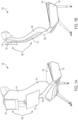
Figure 1A is a rear perspective view of a passenger seat assembly with moveable shroud members attached to a stationary shroud, according to certain embodiments of the present invention. -
Figure 1B is a left side view of the passenger seat assembly ofFIG. 1A . -
Figure 1C is a left side view of the passenger seat assembly ofFIG. 1A moving from a stowed position to a deployed position. -
Figure 2A is a rear perspective view of a passenger seat assembly with moveable shroud members attached to a stationary shroud, according to certain embodiments of the present invention. -
Figure 2B is a rear perspective view of the passenger seat assembly ofFIG. 2A with the location of the moveable shroud members on the stationary shroud adjusted. -
Figure 3 is a rear view of a passenger seat assembly with moveable shroud members attached to a stationary shroud installed in a row of passenger seat assemblies, according to certain embodiments of the present invention. -
Figure 4 is a rear view of a passenger seat assembly with a stationary shroud, according to certain embodiments of the present invention. -
Figure 5 is a rear view of a passenger seat assembly with a stationary shroud, according to certain embodiments of the present invention. -
Figure 6 is a partial perspective view of a passenger seat assembly with a moveable shroud member attached to a stationary shroud using a snap-fit connection, according to certain embodiments of the present invention. -
Figure 7 is a partial perspective view of a passenger seat assembly with a moveable shroud member attached to a stationary shroud using a friction-fit connection, according to certain embodiments of the present invention. -
Figure 8 is a partial perspective view of a passenger seat assembly with a moveable shroud member attached to a stationary shroud using a connection that fully surrounds the stationary shroud, according to certain embodiments of the present invention. -
Figure 9 is a rear view of a passenger seat assembly with moveable shroud members attached to a stationary shroud, according to certain embodiments of the present invention. - The subject matter of embodiments of the present invention is described here with specificity to meet statutory requirements, but this description is not necessarily intended to limit the scope of the claims. The claimed subject matter may be embodied in other ways, may include different elements or steps, and may be used in conjunction with other existing or future technologies. This description should not be interpreted as implying any particular order or arrangement among or between various steps or elements except when the order of individual steps or arrangement of elements is explicitly described.
- The described embodiments of the invention provide moveable shroud members attachable to a stationary shroud for passenger seats with the moveable shroud members being moveable along the stationary shroud. While the moveable shroud members are discussed for use with aircraft seats, they are by no means so limited. Rather, embodiments of the moveable shroud members may be used in passenger seats or other seats of any type or otherwise as desired.
- According to certain embodiments of the present invention, as shown in
FIGS. 1A-1C ,moveable shroud members 108 are attached to astationary shroud 106, which may also be referred to as a seat shroud. Thestationary shroud 106 is part of apassenger seat assembly 100. Thepassenger seat assembly 100 may also include aseat frame 102, aseat back 104, aseat pan 118, and thestationary shroud 106, e.g., a monitor shroud, a seat shroud, or a non-intrusive stationary shroud. In some embodiments, themoveable shroud members 108 may include avideo monitor screen 110 or a tray table 112. Themoveable shroud members 108 may include additional devices, which are discussed in further detail below in relation toFIG. 9 . - The
seat frame 102, theseat back 104, thestationary shroud 106, themoveable shroud members 108, and theseat pan 118 may be formed of materials including but not limited to aluminum, stainless steel, aramid fibers, polycarbonate, polypropylene, other metallic materials, composite materials, or other suitable materials. In some embodiments, thevideo monitor screen 110 may include a plasma display, a liquid crystal display, an organic light-emitting diode display, a projector, or any other suitable screen or device for displaying images. Each of theseat frame 102, theseat back 104, thestationary shroud 106, themoveable shroud members 108, and theseat pan 118 may be formed from the same material, from different materials, or from a combination of the same and different materials. For example, theseat frame 102 and theseat back 104 may both be formed of aluminum, thestationary shroud 106 may be formed from polycarbonate, and themoveable shroud members 108 may be formed from composite materials. In certain embodiments, theseat back 104, themoveable shroud members 108, and theseat pan 118 may be covered by a cushioning material. - In some embodiments, the
seat back 104 may be supported by theseat frame 102, and theseat frame 102 may be coupled with a seat track fitting to secure theseat frame 102, and thus thepassenger seat assembly 100, to the floor of the passenger vehicle. Theseat back 104 may include arearward surface 114, which is opposite a forward surface that a passenger sitting in thepassenger seat assembly 100 comes into contact with. - In some embodiments, the
stationary shroud 106 may be fixedly attached to any suitable stationary surface found within the passenger vehicle, such as theseat frame 102, the seat track, a floor surface, a wall surface, a ceiling surface, an overhead bin surface, etc. For example, thestationary shroud 106 may be integrally formed with the floor surface or may be secured to the wall surface using any suitable attachment, e.g., screws, nuts and bolts, glue, sealant, a snap-fit design, a friction-fit design, welding, melting, etc. - In some embodiments, as shown in
FIGS. 1A-1C , thestationary shroud 106 is fixedly attached to theseat frame 102 and positioned proximate to, but separate from, therearward surface 114 of theseat back 104. The positioning of thestationary shroud 106 permits access to therearward surface 114 of the seat back 104. - In some embodiments, the
seat back 104 may be movable between a stowed position, e.g., a substantially upright position, and a deployed position, e.g., a substantially reclined position. This movement of the seat back 104 between the stowed position and the deployed position is represented by thearrow 116 inFIG. 1C . In some embodiments, theseat back 104 may be fixedly coupled to theseat pan 118 such that when theseat back 104 is moved between a stowed position and a deployed position the seat back 104 and theseat pan 118 move together through a cradle or rocking motion that includes the simultaneous translation and rotation of the seat back 104 and theseat pan 118. In further embodiments, theseat back 104 may be pivotally coupled to theseat pan 118 such that theseat back 104 may be moved between the stowed position and the deployed position by rotating the seat back 104 relative to theseat pan 118 as theseat pan 118 remains stationary. - According to certain embodiments of the present invention, such as shown in
FIGS. 2A-2B ,moveable shroud members 208 are attached to astationary shroud 206 as part of apassenger seat assembly 200. Thepassenger seat assembly 200 may be similar to or the same as, or include similar or the same elements as, thepassenger seat assembly 100 discussed above with respect toFIGS. 1A-1C . For example, thepassenger seat assembly 200 may also include aseat frame 202, a seat back 204, and thestationary shroud 206. - The
moveable shroud members 208 may include avideo monitor screen 210 and/or a tray table 212, which may be the same as thevideo monitor screen 110 and the tray table 112 discussed above with respect toFIGS. 1A-1C . Themoveable shroud members 208 are attached to thestationary shroud 206 at attachment points. Eachmoveable shroud member 208 may have one or more attachment points. For example, thevideo monitor screen 210 may be attached to thestationary shroud 206 at a first attachment point and a second attachment point and the tray table 212 may be attached to thestationary shroud 206 at a third attachment point. The first attachment point may be proximate an upper edge of thevideo monitor screen 210 and the second attachment point may be proximate a lower edge of thevideo monitor screen 210. - In some embodiments, the
moveable shroud members 208 may be attached to thestationary shroud 206 without embedding themoveable shroud members 208 in thestationary shroud 206, the seat back 204, or any other feature of thepassenger seat assembly 200. Attaching themoveable shroud members 208 to thestationary shroud 206 without embedding themoveable shroud members 208 in thestationary shroud 206 or seat back 204 provides designers with new and different design options for thepassenger seat assembly 200. - For example, the seat back 204 may be designed without having to consider the placement of the
moveable shroud members 208 on the seat back 204 or the potential effect that any movement of the seat back 204 between the stowed position and the deployed position might have on themoveable shroud members 208. Additionally, a larger variety of sizes of themoveable shroud members 208 may be used when themoveable shroud members 208 are attached to thestationary shroud 206 and are not embedded in thestationary shroud 206 or the seat back 204. - In some embodiments, the
video monitor screen 210, or any other suitablemoveable shroud member 208, may extend an entire width of the seat back 204 of thepassenger seat assembly 200. Increasing the size of thevideo monitor screen 210 may permit increased functionality of thevideo monitor screen 210. For example, a passenger may be able to control their full environment, e.g., an overhead light, an amount of airflow from an overhead fan, a flight attendant call light, etc., all from thevideo monitor screen 210. Incorporating such functionality into thevideo monitor screen 210 means that the buttons or other mechanisms currently used to control those features may be removed from the aircraft or passenger vehicle. So the overall weight of the aircraft or passenger vehicle may be reduced. - In some embodiments, the location of the attachment point, or attachment points, of each
moveable shroud member 208 on thestationary shroud 206 may be adjustable. This adjustable attachment point may permit themoveable shroud members 208 to be moved to various locations along thestationary shroud 206. For example, thearrow 214 and thearrow 216 represent potential movement of thevideo monitor screen 210 and the tray table 212, respectively, as the location of each attachment point is adjusted. Themoveable shroud members 208 may be arranged so that eachmoveable shroud member 208 is capable of independent movement or so that multiplemoveable shroud members 208 may be moved in unison. A passenger may adjust the attachment point of themoveable shroud members 208 based on the passenger's height or any other factor to increase the passenger's comfort level, to adjust the amount of living space available to the passenger, to allow for easier access to themoveable shroud members 208, etc. - In some embodiments, the
moveable shroud members 208 may be coupled with thestationary shroud 206 using a tilting mechanism that permits the angle of themovable shroud member 208 relative to thestationary shroud 206 to be adjusted by pivoting themoveable shroud members 208. In further embodiments, themoveable shroud members 208 may be coupled with thestationary shroud 206 without incorporating such a tilting mechanism. Because themoveable shroud members 208 are coupled with thestationary shroud 206, the angle of themoveable shroud members 208 is not affected by any movement of the seat back 204. - In some embodiments, the
moveable shroud members 208 may slide along thestationary shroud 206 to adjust the attachment points. In further embodiments, themoveable shroud members 208 may be detached from thestationary shroud 206 and then reattached to thestationary shroud 206 to adjust the location of the attachment point of eachmoveable shroud member 208. For example, thevideo monitor screen 210 may be removed from the location on thestationary shroud 206 seen inFIG. 2A and reattached to the attachment point on thestationary shroud 206 seen inFIG. 2B . Additionally, themoveable shroud member 208 may be interchangeable. For example, thevideo monitor screen 210 may be removed from thestationary shroud 206 and a differentvideo monitor screen 210, or a different type ofmoveable shroud member 208, may be attached to thestationary shroud 206. So the size, style, features, etc. of themoveable shroud member 208 may be changed by switching onemoveable shroud member 208 for anothermoveable shroud member 208. - According to certain embodiments of the present invention, such as shown in
FIG. 3 , apassenger seat row 310 may include multiple individualpassenger seat assemblies 300 arranged proximate to one another in a row. The individualpassenger seat assemblies 300 may be similar to or the same as, or include similar or the same elements as, thepassenger seat assemblies FIGS. 1A-1C andFIGS. 2A-2B , respectively. For example, thepassenger seat assembly 300 may include aseat frame 302, a seat back 304, astationary shroud 306, andmoveable shroud members 308 attached to thestationary shroud 306. - As shown in
FIGS. 4 and 5 , astationary shroud stationary shroud passenger seat assembly passenger seat assembly stationary shroud FIGS. 1A- 3 , respectively. - In some embodiments, as is shown in
FIG. 4 , thestationary shroud 406 may be substantially tubular shaped or include a substantially tubular shaped portion. The substantially tubular shape may have a circular, rectangular, triangular, oval, square, diamond, or any other suitably shaped cross-section. Thestationary shroud 406 may extend substantially vertically or in any other suitable direction and may be positioned substantially centrally, proximate a right edge, proximate a left edge, or in any other suitable position relative to thepassenger seat assembly 400. - In some embodiments, as is shown in
FIG. 5 , thestationary shroud 506 may be shaped similar to an elongated-upside-down U shape. WhileFIGS. 4 and 5 show various embodiments of thestationary shroud stationary shroud passenger seat assembly - According to certain embodiments of the present invention, such as shown in
FIGS. 6-8 ,moveable shroud members stationary shroud passenger seat assembly passenger seat assembly FIGS. 1A-5 . - In some embodiments, the
moveable shroud member 608 may be attached to thestationary shroud 606 at an attachment point using anattachment member 610. The location of the attachment point of themoveable shroud member 608 may be changed by either moving themoveable shroud member 608 along theattachment member 610 or by moving theattachment member 610 along thestationary shroud 606. Theattachment member 610 may attach to thestationary shroud 606 using a snap-fit coupling or connection. In further embodiments, themoveable shroud member 608 may be directly coupled to thestationary shroud 606 at an attachment point without the use of theattachment member 610. - In some embodiments, the
attachment member 610 may have a universal coupling that fits with a universal receptor of thestationary shroud 606 so that the universal receptor may receive theattachment member 610. The universal receptor of thestationary shroud 606 may be the shape of thestationary shroud 606, an indentation, opening, cut-through, etc. in thestationary shroud 606, or any other suitable feature that may permit the universal coupling to fit with the universal receptor. The universal receptor may enable anymoveable shroud member 608 that has the corresponding universal coupling to attach to thestationary shroud 606. - The use of the universal receptor and the universal coupling may facilitate moving the
moveable shroud member 608 along thestationary shroud 606 and/or interchanging onemoveable shroud member 608 for a differentmoveable shroud member 608. For example, a firstmoveable shroud member 608 attached to thestationary shroud 606 may be removed from thestationary shroud 606 and replaced with a secondmoveable shroud member 608 that has asecond attachment member 610 with the universal coupling. The universal coupling of thesecond attachment member 610 is compatible with the universal receptor of thestationary shroud 606 so that the secondmoveable shroud member 608 may be coupled with thestationary shroud 606 via thesecond attachment member 610 at an attachment point. The attachment point of the secondmoveable shroud member 608 may similarly be adjusted along thestationary shroud 606. - In some embodiments, as shown in
FIG. 7 , themoveable shroud member 708 may be attached to thestationary shroud 706 at an attachment point using anattachment member 710. Themoveable shroud member 708, thestationary shroud 706, and theattachment member 710 may have all or some of the same or similar features as are described above with regards to themoveable shroud member 608 , thestationary shroud 606, and theattachment member 610 shown inFIG. 6 . - In some embodiments, the
attachment member 710 may attach to thestationary shroud 706 using a friction-fit coupling or connection. Additionally, thestationary shroud 706 may have a universal receptor that is compatible with theattachment member 710 so that thestationary shroud 706 may receive theattachment member 710 and be coupled with themoveable shroud member 708. In further embodiments, theattachment member 710 may also have a universal coupling that fits with the universal receptor so that themoveable shroud member 708 may be attached to thestationary shroud 706. - In some embodiments, as shown in
FIG. 8 , themoveable shroud member 808 may be attached to thestationary shroud 806 at an attachment point using anattachment member 810. Themoveable shroud member 808, thestationary shroud 806, and theattachment member 810 may have all or some of the same or similar features as are described above with regards to themoveable shroud member stationary shroud attachment member FIGS. 6, 7 , respectively. - In some embodiments, the
attachment member 810 may attach to thestationary shroud 806 and entirely surround a portion of thestationary shroud 806. Theattachment member 810 may include alocking device 812 that requires a moveablemember removing tool 814 to completely remove themoveable shroud member 808 from thestationary shroud 806. For example, thelocking device 812 of theattachment member 810 may be a fastener with a specially designed head that only fits with a moveablemember removing tool 814. Themoveable shroud member 808 may be removed from thestationary shroud 806 when the fastener is removed or rotated a specific amount using the moveablemember removing tool 814. Thelocking device 812 and the moveablemember removing tool 814 may be any suitable compatible devices. - In further embodiments, the
attachment member 810 may require the moveablemember removing tool 814 to completely remove themoveable shroud member 808 from thestationary shroud 806, but the attachment point of themoveable shroud member 808 may be adjusted without the use of the moveablemember removing tool 814. Being able to adjust the attachment point of themoveable shroud member 808 without needing the moveablemember removing tool 814 may enable a passenger to adjust the location of themoveable shroud member 808 without removing themoveable shroud member 808 from thestationary shroud 806 and may reduce the risk of theft of themoveable shroud member 808. - According to certain embodiments of the present invention, such as shown in
FIG. 9 ,moveable shroud members 908 are attached to astationary shroud 906 as part of apassenger seat assembly 900. Thepassenger seat assembly 900 may be similar to or the same as, or include similar or the same elements as, the passenger seat assembly 100-800 and the stationary shroud 106-806, discussed above in reference toFIGS. 1A-8 , respectively. - In some embodiments, the
moveable shroud members 908 may include alight source 910, a personal-electronic-device holder 912, aheadrest 914, acup holder 916, aliterature pocket 918, or any other suitable element. Themoveable shroud member 908 may be removably attached to thestationary shroud 906 in any arrangement and may be moved to various locations along thestationary shroud 906. Any suitable number, e.g., 1, 2, 3, 4, 5, etc., ofmoveable shroud members 908 may be attached to thestationary shroud 906 and themoveable shroud member 908 may also be attached to thestationary shroud 906 with a video monitor screen and/or a tray table. - The present invention is not limited to the embodiments described above or depicted in the drawings, and various embodiments and modifications may be made without departing from the scope of the claims below.
Claims (12)
- A passenger seat assembly comprising:a seat back (104) comprising a rearward surface (114);a seat frame (102);a seat shroud (106) positioned proximate to the rearward surface of the seat back and fixedly coupled to the seat frame, wherein the seat shroud remains stationary as the seat back moves between a stowed position and a deployed position, and wherein the seat shroud permits access to at least a portion of the rearward surface of the seat back; andat least one moveable shroud member (108) coupled to the seat shroud at an attachment point and positioned proximate a rearward surface of the seat shroud,wherein a location of the attachment point is adjustable.
- The passenger seat assembly of claim 1, characterized in that the at least one moveable shroud member (108) comprises at least one of a monitor screen, a tray table, a reading light, a cup holder, a literature pocket, a personal electronic device holder, or a headrest.
- The passenger seat assembly of claim 1 or 2, characterized in that the adjustable location of the attachment point adjusts a location of the moveable shroud member (108) relative to the seat shroud (106).
- The passenger seat assembly of any of the claims 1 to 3, characterized in that the at least one moveable shroud member (108) is interchangeable with at least one second moveable shroud member.
- The passenger seat assembly of any of the claims 1 to 4, characterized in that the at least one moveable shroud member (108) remains stationary as the seat back moves between the stowed position and the deployed position.
- The passenger seat assembly of any of the claims 1 to 5, characterized in that the seat shroud (106) comprises a substantially tubular shape.
- The passenger seat assembly of any of the claims 1 to 6, characterized in that the moveable shroud member (108) comprises an attachment member (610, 710, 810), wherein:the moveable shroud member is coupled to the seat shroud (106) at the attachment point using the attachment member,the seat shroud comprises a universal receptor configured to receive the attachment member,the attachment member comprises a universal coupling configured to fit with the universal receptor of the seat shroud (106).
- The passenger seat assembly of claim 7, characterized in that the attachment member comprises at least one of a snap-fit coupling or a friction-fit coupling.
- The passenger seat assembly of claim 7 or 8, characterized in that the attachment member at least partly surrounds at least a portion of the seat shroud.
- The passenger seat assembly of any of the claims 1 to 9, characterized in that the moveable shroud member (108) must be removed from the seat shroud using a moveable shroud member removing tool.
- The passenger seat assembly of claim 10, characterized in that the location of the attachment point on the seat shroud is adjustable without using the moveable shroud member removing tool.
- The passenger seat assembly of any of the claims 1 to 11, characterized in that it further comprises:at least one second interchangeable-moveable shroud member coupled to the seat shroud at a second attachment point, wherein the location of the second attachment point is adjustable and the at least one second interchangeable-moveable shroud member replaces the at least one moveable shroud member (108); andat least one second attachment member configured to attach the at least one second interchangeable-moveable shroud member to the seat shroud at the attachment point.
Applications Claiming Priority (1)
| Application Number | Priority Date | Filing Date | Title |
|---|---|---|---|
| PCT/US2020/021386 WO2021177971A1 (en) | 2020-03-06 | 2020-03-06 | Moveable shroud member |
Publications (2)
| Publication Number | Publication Date |
|---|---|
| EP4114728A1 EP4114728A1 (en) | 2023-01-11 |
| EP4114728B1 true EP4114728B1 (en) | 2024-07-17 |
Family
ID=70110365
Family Applications (1)
| Application Number | Title | Priority Date | Filing Date |
|---|---|---|---|
| EP20716291.8A Active EP4114728B1 (en) | 2020-03-06 | 2020-03-06 | Moveable shroud member |
Country Status (4)
| Country | Link |
|---|---|
| US (1) | US12246836B2 (en) |
| EP (1) | EP4114728B1 (en) |
| CN (1) | CN115243974B (en) |
| WO (1) | WO2021177971A1 (en) |
Families Citing this family (1)
| Publication number | Priority date | Publication date | Assignee | Title |
|---|---|---|---|---|
| US20250100685A1 (en) * | 2023-09-25 | 2025-03-27 | Gentex Corporation | Tray for passenger seat with display |
Citations (1)
| Publication number | Priority date | Publication date | Assignee | Title |
|---|---|---|---|---|
| CN108422905A (en) * | 2018-05-03 | 2018-08-21 | 陈永铵 | Lying chair with shank supporting plate capable of ascending and descending along with front chair back |
Family Cites Families (20)
| Publication number | Priority date | Publication date | Assignee | Title |
|---|---|---|---|---|
| US3594037A (en) * | 1970-04-09 | 1971-07-20 | Mc Donnell Douglas Corp | Cabin attendant seat |
| IT1306152B1 (en) | 1999-06-02 | 2001-05-30 | Aviointeriors Spa | ARMCHAIR WITH PERFECTED CRADLE MOVEMENT, IN PARTICULAR AIRCRAFT. |
| GB9918263D0 (en) | 1999-08-04 | 1999-10-06 | Britax Rumbold Ltd | Seating unit of a passenger vehicle |
| US6742840B2 (en) | 2001-05-25 | 2004-06-01 | Weber Aircraft Lp | Adjustable seats |
| DE202004008069U1 (en) | 2004-05-13 | 2004-07-29 | Tricon Aktiengesellschaft | Seat assembly for especially passengers in aircraft has stowage compartment for hand luggage and is located below level of sitting surface or below foot level, with sitting surface raised by the height of stowage compartment |
| DE102005017713B4 (en) | 2005-04-15 | 2007-10-31 | Grammer Ag | Vehicle seat with deformable backrest |
| US8167244B2 (en) | 2008-02-11 | 2012-05-01 | B E Aerospace, Inc. | Class divider for aircraft cabin |
| GB2469180B8 (en) | 2009-03-23 | 2016-06-08 | Air New Zealand Ltd | Vehicle seating arrangement |
| US9045096B2 (en) * | 2010-05-14 | 2015-06-02 | Zodiac Seats Us Llc | Coupling assembly |
| EP2718184B1 (en) | 2011-06-10 | 2016-08-31 | Zodiac Seats US LLC | Passenger seat assembly |
| DE102012217802B4 (en) | 2012-09-28 | 2018-12-20 | Lufthansa Technik Ag | Attachment system for passenger equipment in an aircraft |
| CA2902891C (en) | 2013-04-08 | 2017-08-22 | B/E Aerospace, Inc. | Aircraft seat employing dual actuators for seat translation and seat recline |
| DE102013012291A1 (en) | 2013-07-24 | 2015-01-29 | Man Truck & Bus Ag | Vehicle seat, in particular passenger seat for a bus |
| CN105173089A (en) | 2015-09-30 | 2015-12-23 | 南京大学 | Seat with waist pad |
| US11066171B2 (en) | 2016-04-04 | 2021-07-20 | B/E Aerospace, Inc. | Contoured class divider |
| US10370106B2 (en) | 2016-04-04 | 2019-08-06 | B/E Aerospace, Inc. | Contoured class divider |
| WO2018057117A1 (en) | 2016-09-26 | 2018-03-29 | Zodiac Seats Us Llc | Amenities panel for passenger seat for holding passenger belongings and devices |
| DE102017205800A1 (en) | 2017-04-05 | 2018-10-11 | Airbus Operations Gmbh | Passenger seat with movable backrest and seating group for installation in a vehicle |
| JP2019147477A (en) | 2018-02-27 | 2019-09-05 | コイト電工株式会社 | Seat device |
| WO2021066800A1 (en) | 2019-09-30 | 2021-04-08 | Safran Seats Usa Llc | Non-intrusive stationary monitor shroud |
-
2020
- 2020-03-06 CN CN202080098128.XA patent/CN115243974B/en active Active
- 2020-03-06 US US17/797,877 patent/US12246836B2/en active Active
- 2020-03-06 EP EP20716291.8A patent/EP4114728B1/en active Active
- 2020-03-06 WO PCT/US2020/021386 patent/WO2021177971A1/en not_active Ceased
Patent Citations (1)
| Publication number | Priority date | Publication date | Assignee | Title |
|---|---|---|---|---|
| CN108422905A (en) * | 2018-05-03 | 2018-08-21 | 陈永铵 | Lying chair with shank supporting plate capable of ascending and descending along with front chair back |
Also Published As
| Publication number | Publication date |
|---|---|
| WO2021177971A1 (en) | 2021-09-10 |
| CN115243974B (en) | 2025-07-04 |
| EP4114728A1 (en) | 2023-01-11 |
| US12246836B2 (en) | 2025-03-11 |
| US20230059294A1 (en) | 2023-02-23 |
| CN115243974A (en) | 2022-10-25 |
Similar Documents
| Publication | Publication Date | Title |
|---|---|---|
| EP4013679B1 (en) | An aircraft cabin | |
| EP2209402B1 (en) | Convertible passenger seat assembly | |
| EP3129289B1 (en) | A seat unit | |
| EP2086833B1 (en) | Translatable and rotatable passenger seat | |
| US20160159481A1 (en) | Passenger seat with full seatback video display | |
| US7585022B2 (en) | Vehicle seat system, especially for aircraft | |
| EP3347271B1 (en) | Front row module | |
| EP2718184B1 (en) | Passenger seat assembly | |
| US20210061473A1 (en) | Headrest for accommodating ponytail or bun of hair | |
| EP4037969B1 (en) | Non-intrusive stationary monitor shroud | |
| EP3283370B1 (en) | Portable electronic device holder | |
| US20220001992A1 (en) | Aircraft seat and cabin arrangement | |
| EP4114728B1 (en) | Moveable shroud member | |
| US12428157B2 (en) | Passenger seating with front row bulkhead integration | |
| US12565318B2 (en) | Passenger seating unit with half shell surround | |
| US12559239B2 (en) | Integrated seat assembly with headrest and neck support | |
| EP4480821B1 (en) | Integrated seat assembly with headrest and neck support | |
| EP4232362A1 (en) | Tray table with amenities for a passenger seat |
Legal Events
| Date | Code | Title | Description |
|---|---|---|---|
| STAA | Information on the status of an ep patent application or granted ep patent |
Free format text: STATUS: UNKNOWN |
|
| STAA | Information on the status of an ep patent application or granted ep patent |
Free format text: STATUS: THE INTERNATIONAL PUBLICATION HAS BEEN MADE |
|
| PUAI | Public reference made under article 153(3) epc to a published international application that has entered the european phase |
Free format text: ORIGINAL CODE: 0009012 |
|
| STAA | Information on the status of an ep patent application or granted ep patent |
Free format text: STATUS: REQUEST FOR EXAMINATION WAS MADE |
|
| 17P | Request for examination filed |
Effective date: 20220808 |
|
| AK | Designated contracting states |
Kind code of ref document: A1 Designated state(s): AL AT BE BG CH CY CZ DE DK EE ES FI FR GB GR HR HU IE IS IT LI LT LU LV MC MK MT NL NO PL PT RO RS SE SI SK SM TR |
|
| DAV | Request for validation of the european patent (deleted) | ||
| DAX | Request for extension of the european patent (deleted) | ||
| GRAP | Despatch of communication of intention to grant a patent |
Free format text: ORIGINAL CODE: EPIDOSNIGR1 |
|
| STAA | Information on the status of an ep patent application or granted ep patent |
Free format text: STATUS: GRANT OF PATENT IS INTENDED |
|
| INTG | Intention to grant announced |
Effective date: 20240417 |
|
| GRAS | Grant fee paid |
Free format text: ORIGINAL CODE: EPIDOSNIGR3 |
|
| GRAA | (expected) grant |
Free format text: ORIGINAL CODE: 0009210 |
|
| STAA | Information on the status of an ep patent application or granted ep patent |
Free format text: STATUS: THE PATENT HAS BEEN GRANTED |
|
| AK | Designated contracting states |
Kind code of ref document: B1 Designated state(s): AL AT BE BG CH CY CZ DE DK EE ES FI FR GB GR HR HU IE IS IT LI LT LU LV MC MK MT NL NO PL PT RO RS SE SI SK SM TR |
|
| REG | Reference to a national code |
Ref country code: CH Ref legal event code: EP |
|
| REG | Reference to a national code |
Ref country code: DE Ref legal event code: R096 Ref document number: 602020034088 Country of ref document: DE |
|
| REG | Reference to a national code |
Ref country code: IE Ref legal event code: FG4D |
|
| REG | Reference to a national code |
Ref country code: LT Ref legal event code: MG9D |
|
| REG | Reference to a national code |
Ref country code: NL Ref legal event code: MP Effective date: 20240717 |
|
| PG25 | Lapsed in a contracting state [announced via postgrant information from national office to epo] |
Ref country code: PT Free format text: LAPSE BECAUSE OF FAILURE TO SUBMIT A TRANSLATION OF THE DESCRIPTION OR TO PAY THE FEE WITHIN THE PRESCRIBED TIME-LIMIT Effective date: 20241118 |
|
| REG | Reference to a national code |
Ref country code: AT Ref legal event code: MK05 Ref document number: 1703892 Country of ref document: AT Kind code of ref document: T Effective date: 20240717 |
|
| PG25 | Lapsed in a contracting state [announced via postgrant information from national office to epo] |
Ref country code: NL Free format text: LAPSE BECAUSE OF FAILURE TO SUBMIT A TRANSLATION OF THE DESCRIPTION OR TO PAY THE FEE WITHIN THE PRESCRIBED TIME-LIMIT Effective date: 20240717 |
|
| PG25 | Lapsed in a contracting state [announced via postgrant information from national office to epo] |
Ref country code: PT Free format text: LAPSE BECAUSE OF FAILURE TO SUBMIT A TRANSLATION OF THE DESCRIPTION OR TO PAY THE FEE WITHIN THE PRESCRIBED TIME-LIMIT Effective date: 20241118 Ref country code: NL Free format text: LAPSE BECAUSE OF FAILURE TO SUBMIT A TRANSLATION OF THE DESCRIPTION OR TO PAY THE FEE WITHIN THE PRESCRIBED TIME-LIMIT Effective date: 20240717 |
|
| PG25 | Lapsed in a contracting state [announced via postgrant information from national office to epo] |
Ref country code: NO Free format text: LAPSE BECAUSE OF FAILURE TO SUBMIT A TRANSLATION OF THE DESCRIPTION OR TO PAY THE FEE WITHIN THE PRESCRIBED TIME-LIMIT Effective date: 20241017 |
|
| PG25 | Lapsed in a contracting state [announced via postgrant information from national office to epo] |
Ref country code: GR Free format text: LAPSE BECAUSE OF FAILURE TO SUBMIT A TRANSLATION OF THE DESCRIPTION OR TO PAY THE FEE WITHIN THE PRESCRIBED TIME-LIMIT Effective date: 20241018 Ref country code: FI Free format text: LAPSE BECAUSE OF FAILURE TO SUBMIT A TRANSLATION OF THE DESCRIPTION OR TO PAY THE FEE WITHIN THE PRESCRIBED TIME-LIMIT Effective date: 20240717 Ref country code: PL Free format text: LAPSE BECAUSE OF FAILURE TO SUBMIT A TRANSLATION OF THE DESCRIPTION OR TO PAY THE FEE WITHIN THE PRESCRIBED TIME-LIMIT Effective date: 20240717 |
|
| PG25 | Lapsed in a contracting state [announced via postgrant information from national office to epo] |
Ref country code: BG Free format text: LAPSE BECAUSE OF FAILURE TO SUBMIT A TRANSLATION OF THE DESCRIPTION OR TO PAY THE FEE WITHIN THE PRESCRIBED TIME-LIMIT Effective date: 20240717 |
|
| PG25 | Lapsed in a contracting state [announced via postgrant information from national office to epo] |
Ref country code: LV Free format text: LAPSE BECAUSE OF FAILURE TO SUBMIT A TRANSLATION OF THE DESCRIPTION OR TO PAY THE FEE WITHIN THE PRESCRIBED TIME-LIMIT Effective date: 20240717 |
|
| PG25 | Lapsed in a contracting state [announced via postgrant information from national office to epo] |
Ref country code: IS Free format text: LAPSE BECAUSE OF FAILURE TO SUBMIT A TRANSLATION OF THE DESCRIPTION OR TO PAY THE FEE WITHIN THE PRESCRIBED TIME-LIMIT Effective date: 20241117 Ref country code: AT Free format text: LAPSE BECAUSE OF FAILURE TO SUBMIT A TRANSLATION OF THE DESCRIPTION OR TO PAY THE FEE WITHIN THE PRESCRIBED TIME-LIMIT Effective date: 20240717 |
|
| PG25 | Lapsed in a contracting state [announced via postgrant information from national office to epo] |
Ref country code: HR Free format text: LAPSE BECAUSE OF FAILURE TO SUBMIT A TRANSLATION OF THE DESCRIPTION OR TO PAY THE FEE WITHIN THE PRESCRIBED TIME-LIMIT Effective date: 20240717 |
|
| PG25 | Lapsed in a contracting state [announced via postgrant information from national office to epo] |
Ref country code: RS Free format text: LAPSE BECAUSE OF FAILURE TO SUBMIT A TRANSLATION OF THE DESCRIPTION OR TO PAY THE FEE WITHIN THE PRESCRIBED TIME-LIMIT Effective date: 20241017 Ref country code: ES Free format text: LAPSE BECAUSE OF FAILURE TO SUBMIT A TRANSLATION OF THE DESCRIPTION OR TO PAY THE FEE WITHIN THE PRESCRIBED TIME-LIMIT Effective date: 20240717 |
|
| PG25 | Lapsed in a contracting state [announced via postgrant information from national office to epo] |
Ref country code: RS Free format text: LAPSE BECAUSE OF FAILURE TO SUBMIT A TRANSLATION OF THE DESCRIPTION OR TO PAY THE FEE WITHIN THE PRESCRIBED TIME-LIMIT Effective date: 20241017 Ref country code: PL Free format text: LAPSE BECAUSE OF FAILURE TO SUBMIT A TRANSLATION OF THE DESCRIPTION OR TO PAY THE FEE WITHIN THE PRESCRIBED TIME-LIMIT Effective date: 20240717 Ref country code: NO Free format text: LAPSE BECAUSE OF FAILURE TO SUBMIT A TRANSLATION OF THE DESCRIPTION OR TO PAY THE FEE WITHIN THE PRESCRIBED TIME-LIMIT Effective date: 20241017 Ref country code: LV Free format text: LAPSE BECAUSE OF FAILURE TO SUBMIT A TRANSLATION OF THE DESCRIPTION OR TO PAY THE FEE WITHIN THE PRESCRIBED TIME-LIMIT Effective date: 20240717 Ref country code: IS Free format text: LAPSE BECAUSE OF FAILURE TO SUBMIT A TRANSLATION OF THE DESCRIPTION OR TO PAY THE FEE WITHIN THE PRESCRIBED TIME-LIMIT Effective date: 20241117 Ref country code: HR Free format text: LAPSE BECAUSE OF FAILURE TO SUBMIT A TRANSLATION OF THE DESCRIPTION OR TO PAY THE FEE WITHIN THE PRESCRIBED TIME-LIMIT Effective date: 20240717 Ref country code: GR Free format text: LAPSE BECAUSE OF FAILURE TO SUBMIT A TRANSLATION OF THE DESCRIPTION OR TO PAY THE FEE WITHIN THE PRESCRIBED TIME-LIMIT Effective date: 20241018 Ref country code: FI Free format text: LAPSE BECAUSE OF FAILURE TO SUBMIT A TRANSLATION OF THE DESCRIPTION OR TO PAY THE FEE WITHIN THE PRESCRIBED TIME-LIMIT Effective date: 20240717 Ref country code: ES Free format text: LAPSE BECAUSE OF FAILURE TO SUBMIT A TRANSLATION OF THE DESCRIPTION OR TO PAY THE FEE WITHIN THE PRESCRIBED TIME-LIMIT Effective date: 20240717 Ref country code: BG Free format text: LAPSE BECAUSE OF FAILURE TO SUBMIT A TRANSLATION OF THE DESCRIPTION OR TO PAY THE FEE WITHIN THE PRESCRIBED TIME-LIMIT Effective date: 20240717 Ref country code: AT Free format text: LAPSE BECAUSE OF FAILURE TO SUBMIT A TRANSLATION OF THE DESCRIPTION OR TO PAY THE FEE WITHIN THE PRESCRIBED TIME-LIMIT Effective date: 20240717 |
|
| PG25 | Lapsed in a contracting state [announced via postgrant information from national office to epo] |
Ref country code: RO Free format text: LAPSE BECAUSE OF FAILURE TO SUBMIT A TRANSLATION OF THE DESCRIPTION OR TO PAY THE FEE WITHIN THE PRESCRIBED TIME-LIMIT Effective date: 20240717 Ref country code: SM Free format text: LAPSE BECAUSE OF FAILURE TO SUBMIT A TRANSLATION OF THE DESCRIPTION OR TO PAY THE FEE WITHIN THE PRESCRIBED TIME-LIMIT Effective date: 20240717 Ref country code: DK Free format text: LAPSE BECAUSE OF FAILURE TO SUBMIT A TRANSLATION OF THE DESCRIPTION OR TO PAY THE FEE WITHIN THE PRESCRIBED TIME-LIMIT Effective date: 20240717 |
|
| REG | Reference to a national code |
Ref country code: DE Ref legal event code: R097 Ref document number: 602020034088 Country of ref document: DE |
|
| PG25 | Lapsed in a contracting state [announced via postgrant information from national office to epo] |
Ref country code: EE Free format text: LAPSE BECAUSE OF FAILURE TO SUBMIT A TRANSLATION OF THE DESCRIPTION OR TO PAY THE FEE WITHIN THE PRESCRIBED TIME-LIMIT Effective date: 20240717 |
|
| PG25 | Lapsed in a contracting state [announced via postgrant information from national office to epo] |
Ref country code: CZ Free format text: LAPSE BECAUSE OF FAILURE TO SUBMIT A TRANSLATION OF THE DESCRIPTION OR TO PAY THE FEE WITHIN THE PRESCRIBED TIME-LIMIT Effective date: 20240717 |
|
| PG25 | Lapsed in a contracting state [announced via postgrant information from national office to epo] |
Ref country code: SK Free format text: LAPSE BECAUSE OF FAILURE TO SUBMIT A TRANSLATION OF THE DESCRIPTION OR TO PAY THE FEE WITHIN THE PRESCRIBED TIME-LIMIT Effective date: 20240717 |
|
| PLBE | No opposition filed within time limit |
Free format text: ORIGINAL CODE: 0009261 |
|
| STAA | Information on the status of an ep patent application or granted ep patent |
Free format text: STATUS: NO OPPOSITION FILED WITHIN TIME LIMIT |
|
| 26N | No opposition filed |
Effective date: 20250422 |
|
| PG25 | Lapsed in a contracting state [announced via postgrant information from national office to epo] |
Ref country code: SE Free format text: LAPSE BECAUSE OF FAILURE TO SUBMIT A TRANSLATION OF THE DESCRIPTION OR TO PAY THE FEE WITHIN THE PRESCRIBED TIME-LIMIT Effective date: 20240717 |
|
| PG25 | Lapsed in a contracting state [announced via postgrant information from national office to epo] |
Ref country code: MC Free format text: LAPSE BECAUSE OF FAILURE TO SUBMIT A TRANSLATION OF THE DESCRIPTION OR TO PAY THE FEE WITHIN THE PRESCRIBED TIME-LIMIT Effective date: 20240717 |
|
| REG | Reference to a national code |
Ref country code: CH Ref legal event code: H13 Free format text: ST27 STATUS EVENT CODE: U-0-0-H10-H13 (AS PROVIDED BY THE NATIONAL OFFICE) Effective date: 20251023 |
|
| PG25 | Lapsed in a contracting state [announced via postgrant information from national office to epo] |
Ref country code: LU Free format text: LAPSE BECAUSE OF NON-PAYMENT OF DUE FEES Effective date: 20250306 |
|
| REG | Reference to a national code |
Ref country code: BE Ref legal event code: MM Effective date: 20250331 |
|
| PG25 | Lapsed in a contracting state [announced via postgrant information from national office to epo] |
Ref country code: BE Free format text: LAPSE BECAUSE OF NON-PAYMENT OF DUE FEES Effective date: 20250331 |
|
| PG25 | Lapsed in a contracting state [announced via postgrant information from national office to epo] |
Ref country code: CH Free format text: LAPSE BECAUSE OF NON-PAYMENT OF DUE FEES Effective date: 20250331 |
|
| PG25 | Lapsed in a contracting state [announced via postgrant information from national office to epo] |
Ref country code: IE Free format text: LAPSE BECAUSE OF NON-PAYMENT OF DUE FEES Effective date: 20250306 |
|
| PG25 | Lapsed in a contracting state [announced via postgrant information from national office to epo] |
Ref country code: IT Free format text: LAPSE BECAUSE OF FAILURE TO SUBMIT A TRANSLATION OF THE DESCRIPTION OR TO PAY THE FEE WITHIN THE PRESCRIBED TIME-LIMIT Effective date: 20240717 |
|
| PGFP | Annual fee paid to national office [announced via postgrant information from national office to epo] |
Ref country code: GB Payment date: 20260317 Year of fee payment: 7 |
|
| PGFP | Annual fee paid to national office [announced via postgrant information from national office to epo] |
Ref country code: DE Payment date: 20260320 Year of fee payment: 7 |
|
| PGFP | Annual fee paid to national office [announced via postgrant information from national office to epo] |
Ref country code: FR Payment date: 20260324 Year of fee payment: 7 |