EP4114573B1 - Cyclone separator arrangement - Google Patents
Cyclone separator arrangement Download PDFInfo
- Publication number
- EP4114573B1 EP4114573B1 EP20922636.4A EP20922636A EP4114573B1 EP 4114573 B1 EP4114573 B1 EP 4114573B1 EP 20922636 A EP20922636 A EP 20922636A EP 4114573 B1 EP4114573 B1 EP 4114573B1
- Authority
- EP
- European Patent Office
- Prior art keywords
- arrangement
- crossover duct
- flow channel
- preceding apparatus
- width
- Prior art date
- Legal status (The legal status is an assumption and is not a legal conclusion. Google has not performed a legal analysis and makes no representation as to the accuracy of the status listed.)
- Active
Links
Images


Classifications
-
- F—MECHANICAL ENGINEERING; LIGHTING; HEATING; WEAPONS; BLASTING
- F23—COMBUSTION APPARATUS; COMBUSTION PROCESSES
- F23J—REMOVAL OR TREATMENT OF COMBUSTION PRODUCTS OR COMBUSTION RESIDUES; FLUES
- F23J15/00—Arrangements of devices for treating smoke or fumes
- F23J15/02—Arrangements of devices for treating smoke or fumes of purifiers, e.g. for removing noxious material
- F23J15/022—Arrangements of devices for treating smoke or fumes of purifiers, e.g. for removing noxious material for removing solid particulate material from the gasflow
- F23J15/027—Arrangements of devices for treating smoke or fumes of purifiers, e.g. for removing noxious material for removing solid particulate material from the gasflow using cyclone separators
-
- B—PERFORMING OPERATIONS; TRANSPORTING
- B01—PHYSICAL OR CHEMICAL PROCESSES OR APPARATUS IN GENERAL
- B01J—CHEMICAL OR PHYSICAL PROCESSES, e.g. CATALYSIS OR COLLOID CHEMISTRY; THEIR RELEVANT APPARATUS
- B01J8/00—Chemical or physical processes in general, conducted in the presence of fluids and solid particles; Apparatus for such processes
- B01J8/005—Separating solid material from the gas/liquid stream
- B01J8/0055—Separating solid material from the gas/liquid stream using cyclones
-
- B—PERFORMING OPERATIONS; TRANSPORTING
- B04—CENTRIFUGAL APPARATUS OR MACHINES FOR CARRYING-OUT PHYSICAL OR CHEMICAL PROCESSES
- B04C—APPARATUS USING FREE VORTEX FLOW, e.g. CYCLONES
- B04C5/00—Apparatus in which the axial direction of the vortex is reversed
- B04C5/02—Construction of inlets by which the vortex flow is generated, e.g. tangential admission, the fluid flow being forced to follow a downward path by spirally wound bulkheads, or with slightly downwardly-directed tangential admission
- B04C5/04—Tangential inlets
-
- B—PERFORMING OPERATIONS; TRANSPORTING
- B04—CENTRIFUGAL APPARATUS OR MACHINES FOR CARRYING-OUT PHYSICAL OR CHEMICAL PROCESSES
- B04C—APPARATUS USING FREE VORTEX FLOW, e.g. CYCLONES
- B04C5/00—Apparatus in which the axial direction of the vortex is reversed
- B04C5/08—Vortex chamber constructions
- B04C5/081—Shapes or dimensions
-
- B—PERFORMING OPERATIONS; TRANSPORTING
- B04—CENTRIFUGAL APPARATUS OR MACHINES FOR CARRYING-OUT PHYSICAL OR CHEMICAL PROCESSES
- B04C—APPARATUS USING FREE VORTEX FLOW, e.g. CYCLONES
- B04C9/00—Combinations with other devices, e.g. fans, expansion chambers, diffusors, water locks
Definitions
- the invention relates to a cyclone separator arrangement, comprising a preceding apparatus having an outlet and a cyclone separator having an inlet.
- Cyclone separators are widely used for separating or removing particles from gas flow generated e.g. in a reactor, a furnace, an oven, or a venturi. However, there is still a need for improving the efficiency of the cyclone separators.
- a common cyclone separator arrangement is disclosed in document US5203284A .
- a cyclone separator arrangement comprising
- the horizontal cross-section of the preceding apparatus has a round shape, and the crossover duct is arranged to the round preceding apparatus so that a distal wall of the crossover duct is tangentially directed in respect of the preceding apparatus.
- the horizontal cross-section of the preceding apparatus has a round shape
- the distal wall has an offset in respect of the preceding apparatus, the offset being no more than 0.1 ⁇ D from a tangential plane of the preceding apparatus.
- a cross-sectional shape of the preceding apparatus is polygon, e.g. rectangle or square, and that the crossover duct is arranged at a vertical edge of the preceding apparatus so that a distal wall of the crossover duct is attached to said vertical edge.
- a cross-sectional shape of the preceding apparatus is polygon, e.g. rectangle or square, and a distal wall of the crossover duct has an offset in respect of a vertical edge of the preceding apparatus, the offset being no more than 0.1 x D from said vertical edge.
- a cross-sectional shape of the preceding apparatus is polygon, e.g. rectangle or square, and the distal wall of the crossover duct is perpendicular to an outlet wall of the preceding apparatus that comprises the outlet.
- a relation of the height H of the crossover duct to the width d thereof is H/d ⁇ 3.75 at the outlet.
- the cross-sectional area of the crossover duct decreases towards the inlet.
- the width of the crossover duct is decreasing towards the inlet.
- the width of the crossover duct is decreasing towards the inlet so that a proximal wall of the crossover duct is arranged at a first angle ⁇ in relation to a distal wall thereof, wherein the first angle ⁇ ⁇ 40°.
- a bump is arranged in the flow channel for limiting the cross-sectional area of the flow channel.
- the height h of the bump in relation to width d of the flow channel is selected as: h/d ⁇ 0.3.
- the length l of the bump 11 in relation to height h thereof is selected as: l/h ⁇ 4.
- the preceding apparatus is a venturi apparatus having a round cross-section, the venturi apparatus comprising a feeding channel arrangement for feeding material in the venturi apparatus, wherein the feeding channel arrangement comprises one or more feeding channel(s) arranged, as seen from above, at a second angle ⁇ in relation to the direction of the distal wall of the crossover duct, wherein said second angle ⁇ is selected in range of 90° ⁇ 70°.
- the feeding channel arrangement of the venturi apparatus comprises one feeding channel only.
- the feeding channel arrangement comprises at least two feeding channels.
- the feeding channel arrangement is arranged on same side of a centre line of the venturi apparatus as the crossover duct.
- the feeding channel arrangement is arranged on opposite side of a centre line of the venturi apparatus as the crossover duct.
- the venturi apparatus has an expanded upper portion, and that the outlet is arranged to said expanded upper portion.
- Figure 1a is a schematic top view of a cyclone separator arrangement in partial cross-section
- Figure 1b is a schematic side view of the arrangement shown in Figure lain partial cross-section.
- the cyclone separator arrangement 100 comprises a preceding apparatus 1 having an outlet 2, a cyclone separator 3 having an inlet 4, and a crossover duct 5 connected to the outlet 2 and the inlet 4.
- the preceding apparatus 1 is a reactor, a furnace, an oven, or a venturi.
- the preceding apparatus 1 has a horizontal inner diameter D.
- the crossover duct 5 creates a flow channel 6 from the outlet 2 of the preceding apparatus 1 to the inlet 4 of the cyclone separator 3 and supplies gas flow comprising particles from the preceding apparatus 1 to the cyclone separator 3.
- the flow channel 6 is arranged asymmetrically in a horizontal cross-section of the preceding apparatus 1.
- the flow channel 6 has a cross-section having a height H and a width d at the outlet 2 of the preceding apparatus 1.
- the width d of the flow channel 6 relates to the inner diameter D of the preceding apparatus 1 such that 0.15 x D ⁇ d ⁇ 0.6 x D, preferably 0.175 x D ⁇ d ⁇ 0.6 x D, even more preferably 0.2 x D ⁇ d ⁇ 0.6 x D.
- the width d of the flow channel 6 is a dimension of the flow channel 6 in a horizontal plane crossing the centre of gravity CF of a flow-through area of the flow channel 6 at the outlet 2 of the preceding apparatus.
- the inner diameter D is a dimension of the preceding apparatus 1 in a horizontal plane crossing the centre of gravity CP of a flow-through area of the preceding apparatus 1 and being parallel to the width d of the flow channel 6.
- said horizontal plane is situated somewhere between upper and lower walls of cross over duct 5.
- Figures 13a and 13b are showing general principles for defining values of d and D.
- a relation of the height H of the cross-over duct 5 to the width d thereof is H/d ⁇ 3.75 at the outlet 2, such as 1 ⁇ H/d ⁇ 3.75.
- the flow channel 6 has a relatively narrow shape, guiding the particles away from the gas outlet of the cyclone apparatus.
- the flow channel 6 is not too narrow, thus allowing the particles at the outlet 2 of the preceding apparatus to be directed towards the duct wall.
- the horizontal cross-section of the preceding apparatus 1 has a round shape.
- the crossover duct 5 is arranged to the round preceding apparatus 1 so that a distal wall 7 of the crossover duct 5 is tangentially directed in respect of the preceding apparatus 1.
- Figure 2 is a schematic top view of another cyclone separator arrangement in partial cross-section.
- the distal wall 7 has an offset b in respect of the preceding apparatus 1.
- the offset b is no more than 0.1 x D from a tangential plane T of the preceding apparatus 1.
- Figure 3 is a schematic top view of a third cyclone separator arrangement in partial cross-section.
- the cross-sectional area of the crossover duct 5 decreases towards the inlet 4.
- the width d is decreasing towards the inlet 4.
- a proximal wall 10 of the crossover duct 5 is arranged at a first angle ⁇ in relation to a distal wall 7 thereof, wherein the first angle ⁇ ⁇ 40°. In another embodiment, the first angle ⁇ ⁇ 35°.
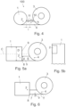
- Figure 4 is a schematic top view of a fourth cyclone separator arrangement in partial cross-section.
- the arrangement 100 comprises a bump 11 arranged in the flow channel 6.
- the bump 11 limits the cross-sectional area of the flow channel 6.
- the bump 11 is attached to the crossover duct 5 by e.g. welding.
- the bump 11 is an integral part of the crossover duct 5, i.e. shaped to the material of the crossover duct 5.
- the bump 11 is arranged to the proximal wall 10 of the crossover duct 5.
- relation of height h of the bump 11 to width d of the flow channel 6 is h/d ⁇ 0.3, preferably h/d ⁇ 0.25.
- relation of length l to height h of the bump 11 is l/h ⁇ 4, preferably l/h ⁇ 3.
- Figure 5a is a schematic top view of a fifth cyclone separator arrangement in partial cross-section
- Figure 5b is a schematic side view of the arrangement shown in Figure 5a in partial cross-section.
- the cross-sectional shape of the preceding apparatus 1 is polygon, such as rectangle.
- the crossover duct 5 is arranged at a vertical edge 8 of the preceding apparatus 1 so that a distal wall 7 of the crossover duct 5 is attached to said vertical edge 8.
- the distal wall 7 of the crossover duct 5 is perpendicular to an outlet wall 9 of the preceding apparatus that comprises the outlet 2. However, in another embodiment, there is an angle differing from 90° between said outer wall 9 and the crossover duct 5.
- Figure 6 is a schematic top view of a sixth cyclone separator arrangement in partial cross-section.
- the distal wall 7 of the crossover duct 5 has an offset b in respect of a vertical edge 8 of the preceding apparatus 1.
- said offset b is not more than 0.1 x D from said vertical edge 8.
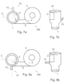
- Figure 7a is a schematic top view of a seventh cyclone separator arrangement in partial cross-section
- Figure 7b is a schematic side view of the arrangement shown in Figure 7a in partial cross-section.
- the preceding apparatus 1 is a venturi apparatus.
- the venturi apparatus 1 has a round cross-section, and it comprises a feeding channel arrangement 12 that is arranged for feeding material in the venturi apparatus. From a fluid dynamic perspective, the round cross-section of the venturi apparatus 1 may be preferable. However, in other embodiments, the cross-section of the venturi apparatus 1 may have another geometry, such as an oval or a polygon geometry.
- the venturi apparatus 1 has an expanded upper portion 14, and the outlet 2 is arranged to said expanded upper portion.
- the expanded upper portion 14 is arranged symmetrically in relation to the overall structure of the venture apparatus. Some embodiments having symmetrical upper portion are shown in Figures 7a - 8b .
- the feeding channel arrangement 12 of the venturi apparatus comprises one feeding channel 13 that is arranged, as seen from above, at a second angle ⁇ in relation to the direction of the distal wall 7 of the crossover duct 5.
- the second angle ⁇ is 90°.
- the second angle ⁇ is selected in range of 90° ⁇ 70°.
- the feeding channel arrangement 12 is arranged on opposite side of a centre line C of the venturi apparatus as the crossover duct 5.
- Figure 8a is a schematic top view of an eighth cyclone separator arrangement in partial cross-section
- Figure 8b is a schematic side view of the arrangement shown in Figure 8a in partial cross-section.
- the feeding channel arrangement 12 is arranged on same side of a centre line C of the venturi apparatus as the crossover duct 5. Also in this embodiment, the second angle ⁇ is selected in range of 90° ⁇ 70°.
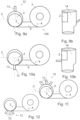
- Figure 9a is a schematic top view of a ninth cyclone separator arrangement in partial cross-section
- Figure 9b is a schematic side view of the arrangement shown in Figure 9a in partial cross-section.
- the venturi apparatus 1 has an expanded upper portion 14 that is arranged asymmetrically in relation to the overall structure of the venture apparatus. Some embodiments having asymmetrical upper portion are shown in Figures 9a - 12 .
- the outlet 2 is arranged to said expanded upper portion.
- the feeding channel arrangement 12 is arranged on opposite side of a centre line C of the venturi apparatus as the crossover duct 5, as shown in Figures 9a, 9b .
- the feeding channel arrangement 12 is arranged on same side of a centre line C of the venturi apparatus as the crossover duct 5, as shown in Figures 10a, 10b .
- the centre line C is the centre line of the upper portion.
- Figure 11 is a schematic top view of an eleventh cyclone separator arrangement in partial cross-section
- Figure 12 is a schematic top view of a twelfth cyclone separator arrangement in partial cross-section.
- the feeding channel arrangement 12 comprises at least two feeding channels 13.
- the number of the feeding channels 13 may be even higher than three.
- the feeding channels 13 of the feeding channel arrangement 12 of the venturi apparatus are arranged in a second angle ⁇ in relation to the direction of the distal wall 7 of the crossover duct 5, the second angle ⁇ being selected in range of 90° ⁇ 70°.
- Figure 13a is showing principles for defining for defining values of d and H of a flow channel
- Figure 13b is showing principles for defining value D of a preceding apparatus.
- Said definition is based on the concept of the centre of gravity.
- a line intersecting said centre CF and parallel to the height of the preceding apparatus 1 is defined. This line represents the height H of the flow channel 6. Then, another line intersecting said centre CF but orthogonal to the height H of the preceding apparatus 1 is defined. This another line represents the width d of the flow channel 6.
Landscapes
- Physics & Mathematics (AREA)
- Fluid Mechanics (AREA)
- Geometry (AREA)
- Engineering & Computer Science (AREA)
- Chemical & Material Sciences (AREA)
- Mechanical Engineering (AREA)
- General Engineering & Computer Science (AREA)
- Organic Chemistry (AREA)
- Chemical Kinetics & Catalysis (AREA)
- Cyclones (AREA)
Description
- The invention relates to a cyclone separator arrangement, comprising a preceding apparatus having an outlet and a cyclone separator having an inlet.
- Cyclone separators are widely used for separating or removing particles from gas flow generated e.g. in a reactor, a furnace, an oven, or a venturi. However, there is still a need for improving the efficiency of the cyclone separators. A common cyclone separator arrangement is disclosed in document
US5203284A . - Viewed from a first aspect, there can be provided a cyclone separator arrangement, comprising
- a preceding apparatus having an outlet, and
- a cyclone separator having an inlet, the arrangement further comprising
- a crossover duct connected to the outlet and the inlet for supplying gas flow comprising particles from the preceding apparatus to the cyclone separator, wherein
- the crossover duct creates a flow channel from the outlet to the inlet,
- the horizontal cross-section of the preceding apparatus has a round shape having a horizontal inner diameter, and wherein
- the width d is a dimension of the flow channel in a horizontal plane crossing the centre of gravity of a flow-through area of the flow channel at the outlet of the preceding apparatus,
wherein - the inner diameter D is a width of the preceding apparatus in a horizontal plane crossing the centre of gravity of a flow-through area of the preceding apparatus and being parallel to the width d of the flow channel, and that
- the flow channel is arranged asymmetrically in a horizontal cross-section of the preceding apparatus, characterized in that the flow channel having a cross-section having a height and a width, said width relating to the inner diameter such that 0.15xD <d<0.6xD, in that the crossover duct is arranged to the round preceding apparatus so that a distal wall of the crossover duct is tangentially directed in respect of the preceding apparatus, and in that a relation of the height H of the crossover duct to the width thereof is H/d<3.75 at the outlet.
- Thereby a cyclone separator arrangement providing improved efficiency may be achieved.
- The arrangement is characterised by what is stated in the independent claim. Some other embodiments are characterised by what is stated in the other claims. Inventive embodiments are also disclosed in the specification and drawings of this patent application. The inventive content of the patent application may also be defined in other ways than defined in the following claims. The inventive content may also be formed of several separate inventions, especially if the invention is examined in the light of expressed or implicit sub-tasks or in view of obtained benefits or benefit groups. Some of the definitions contained in the following claims may then be unnecessary in view of the separate inventive ideas. Features of the different embodiments of the invention may, within the scope of the basic inventive idea, be applied to other embodiments.
- The horizontal cross-section of the preceding apparatus has a round shape, and the crossover duct is arranged to the round preceding apparatus so that a distal wall of the crossover duct is tangentially directed in respect of the preceding apparatus. An advantage is that the separation efficiency of the cyclone separator may be improved by guiding/pushing particles towards the outer wall of said guiding separator already at the outlet of the preceding apparatus.
- In one embodiment, the horizontal cross-section of the preceding apparatus has a round shape, and the distal wall has an offset in respect of the preceding apparatus, the offset being no more than 0.1 × D from a tangential plane of the preceding apparatus. An advantage is that the separation efficiency of the cyclone separator may be improved by guiding/pushing particles towards the outer wall of said guiding separator already at the outlet of the preceding apparatus.
- Not part of the invention, a cross-sectional shape of the preceding apparatus is polygon, e.g. rectangle or square, and that the crossover duct is arranged at a vertical edge of the preceding apparatus so that a distal wall of the crossover duct is attached to said vertical edge. An advantage is that the separation efficiency of the cyclone separator may be improved by guiding/pushing particles towards the outer wall of said guiding separator already at the outlet of the preceding apparatus.
- Not part of the invention, a cross-sectional shape of the preceding apparatus is polygon, e.g. rectangle or square, and a distal wall of the crossover duct has an offset in respect of a vertical edge of the preceding apparatus, the offset being no more than 0.1 x D from said vertical edge. An advantage is that the separation efficiency of the cyclone separator may be improved by guiding/pushing particles towards the outer wall of said guiding separator already at the outlet of the preceding apparatus.
- Not part of the invention, a cross-sectional shape of the preceding apparatus is polygon, e.g. rectangle or square, and the distal wall of the crossover duct is perpendicular to an outlet wall of the preceding apparatus that comprises the outlet. An advantage is that it is very easy to be constructed.
- A relation of the height H of the crossover duct to the width d thereof is H/d < 3.75 at the outlet. An advantage is that the duct flow-through section has a relatively narrow shape, thus guiding the particles away from the cyclone gas outlet.
- In one embodiment, the cross-sectional area of the crossover duct decreases towards the inlet. An advantage is that velocity of gas flow in the cross-over duct may be accelerated.
- In one embodiment, the width of the crossover duct is decreasing towards the inlet. An advantage is that the particles are guided further away from the gas outlet in the cyclone separator. The angle leading to a decreased width pushes the particles further towards the cyclone outer wall where gas solid separation can take place.
- In one embodiment, the width of the crossover duct is decreasing towards the inlet so that a proximal wall of the crossover duct is arranged at a first angle α in relation to a distal wall thereof, wherein the first angle α < 40°. An advantage is that the particles are guided further away from the gas outlet in the cyclone separator. The angle leading to a decreased width pushes the particles further towards the cyclone outer wall where gas solid separation can take place.
- In one embodiment, a bump is arranged in the flow channel for limiting the cross-sectional area of the flow channel. An advantage is that the separation efficiency of the cyclone separator may be enhanced.
- In one embodiment, the height h of the bump in relation to width d of the flow channel is selected as: h/d < 0.3. An advantage is that the flow-through area is not largely occupied by the bump, thus pressure losses do not increase significantly.
- In one embodiment, the length l of the
bump 11 in relation to height h thereof is selected as: l/h < 4. An advantage is that there is enough space left till the cyclone separator inlet is reached, thus allowing the flow to expand back which reduces pressure losses while the particles do not easily expand back due to their inertia. - In one embodiment, the preceding apparatus is a venturi apparatus having a round cross-section, the venturi apparatus comprising a feeding channel arrangement for feeding material in the venturi apparatus, wherein the feeding channel arrangement comprises one or more feeding channel(s) arranged, as seen from above, at a second angle β in relation to the direction of the distal wall of the crossover duct, wherein said second angle β is selected in range of 90° ± 70°. An advantage is that the separation efficiency of the cyclone separator connected to the venturi apparatus may be enhanced.
- In one embodiment, the feeding channel arrangement of the venturi apparatus comprises one feeding channel only. An advantage is that the feeding channel arrangement has a simple and light structure.
- In one embodiment, the feeding channel arrangement comprises at least two feeding channels. An advantage is that this may provide more flexibility to a plant layout and, if necessary, feeding of two or more materials to be mixed in the preceding apparatus may be promoted.
- In one embodiment, the feeding channel arrangement is arranged on same side of a centre line of the venturi apparatus as the crossover duct. An advantage is that the mixing in the venturi is enhanced and also the separation efficiency of the cyclone separator connected to the venturi apparatus may be enhanced, especially when gas flow has a high bulk velocity, meaning that bulk velocity > 5 m/s in the feeding channel, preferably > 6 m/s, even more preferably > 7 m/s.
- In one embodiment, the feeding channel arrangement is arranged on opposite side of a centre line of the venturi apparatus as the crossover duct. An advantage is that the mixing in the venturi is enhanced and also the separation efficiency of the cyclone separator connected to the venturi apparatus may be enhanced, especially when gas flow has a low bulk velocity, meaning that bulk velocity < 5 m/s in the feeding channel, preferably < 4 m/s.
- In one embodiment, the venturi apparatus has an expanded upper portion, and that the outlet is arranged to said expanded upper portion. An advantage is that the venturi enhances mixing due to the expansion and resulting turbulence/recirculation.
- Some embodiments illustrating the present invention are described in more detail in the attached drawings, in which
-
Figure 1a is a schematic top view of a cyclone separator arrangement in partial cross-section, -
Figure 1b is a schematic side view of the arrangement shown in Figure lain partial cross-section, -
Figure 2 is a schematic top view of another cyclone separator arrangement in partial cross-section, -
Figure 3 is a schematic top view of a third cyclone separator arrangement in partial cross-section, -
Figure 4 is a schematic top view of a fourth cyclone separator arrangement in partial cross-section, -
Figure 5a , not part of the invention, is a schematic top view of a fifth cyclone separator arrangement in partial cross-section, -
Figure 5b , not part of the invention, is a schematic side view of the arrangement shown inFigure 5a in partial cross-section, -
Figure 6 , not part of the invention, is a schematic top view of a sixth cyclone separator arrangement in partial cross-section, -
Figure 7a is a schematic top view of a seventh cyclone separator arrangement in partial cross-section, -
Figure 7b is a schematic side view of the arrangement shown inFigure 7a in partial cross-section, -
Figure 8a is a schematic top view of an eighth cyclone separator arrangement in partial cross-section, -
Figure 8b is a schematic side view of the arrangement shown inFigure 8a in partial cross-section, -
Figure 9a is a schematic top view of a ninth cyclone separator arrangement in partial cross-section, -
Figure 9b is a schematic side view of the arrangement shown inFigure 9a in partial cross-section, -
Figure 10a is a schematic top view of a tenth cyclone separator arrangement in partial cross-section, -
Figure 10b is a schematic side view of the arrangement shown inFigure 10a in partial cross-section, -
Figure 11 is a schematic top view of an eleventh cyclone separator arrangement in partial cross-section, -
Figure 12 is a schematic top view of a twelfth cyclone separator arrangement in partial cross-section, -
Figure 13a shows principles for defining certain dimensions of a flow channel, and -
Figure 13b shows principles for defining certain dimensions of a preceding apparatus. - In the figures, some embodiments are shown simplified for the sake of clarity. Similar parts are marked with the same reference numbers in the figures.
-
Figure 1a is a schematic top view of a cyclone separator arrangement in partial cross-section, andFigure 1b is a schematic side view of the arrangement shown in Figure lain partial cross-section. - The
cyclone separator arrangement 100 comprises apreceding apparatus 1 having anoutlet 2, acyclone separator 3 having aninlet 4, and acrossover duct 5 connected to theoutlet 2 and theinlet 4. According to an aspect, thepreceding apparatus 1 is a reactor, a furnace, an oven, or a venturi. Thepreceding apparatus 1 has a horizontal inner diameter D. - The
crossover duct 5 creates aflow channel 6 from theoutlet 2 of thepreceding apparatus 1 to theinlet 4 of thecyclone separator 3 and supplies gas flow comprising particles from thepreceding apparatus 1 to thecyclone separator 3. - The
flow channel 6 is arranged asymmetrically in a horizontal cross-section of thepreceding apparatus 1. - The
flow channel 6 has a cross-section having a height H and a width d at theoutlet 2 of thepreceding apparatus 1. The width d of theflow channel 6 relates to the inner diameter D of thepreceding apparatus 1 such that 0.15 x D < d < 0.6 x D, preferably 0.175 x D < d < 0.6 x D, even more preferably 0.2 x D < d < 0.6 x D. - The wider the
flow channel 6 at its inlet, i.e. at theoutlet 2 of the preceding apparatus, (a higher value before the < d), the smaller the pressure losses are. However, theflow channel 6 at its inlet should not be too wide, because then the particles are not thrown towards the opposite duct wall and separation efficiency of thecyclone apparatus 1 is not enhanced. - The width d of the
flow channel 6 is a dimension of theflow channel 6 in a horizontal plane crossing the centre of gravity CF of a flow-through area of theflow channel 6 at theoutlet 2 of the preceding apparatus. - The inner diameter D is a dimension of the
preceding apparatus 1 in a horizontal plane crossing the centre of gravity CP of a flow-through area of thepreceding apparatus 1 and being parallel to the width d of theflow channel 6. In an embodiment, said horizontal plane is situated somewhere between upper and lower walls of cross overduct 5. -
Figures 13a and 13b are showing general principles for defining values of d and D. - In an embodiment, a relation of the height H of the
cross-over duct 5 to the width d thereof is H/d < 3.75 at theoutlet 2, such as 1 < H/d < 3.75. Thus, theflow channel 6 has a relatively narrow shape, guiding the particles away from the gas outlet of the cyclone apparatus. However, theflow channel 6 is not too narrow, thus allowing the particles at theoutlet 2 of the preceding apparatus to be directed towards the duct wall. - In an embodiment, the horizontal cross-section of the
preceding apparatus 1 has a round shape. In an embodiment, such as shown inFigure 1a , thecrossover duct 5 is arranged to theround preceding apparatus 1 so that adistal wall 7 of thecrossover duct 5 is tangentially directed in respect of thepreceding apparatus 1. -
Figure 2 is a schematic top view of another cyclone separator arrangement in partial cross-section. - In an embodiment of an arrangement where the
preceding apparatus 1 has a round shape, thedistal wall 7 has an offset b in respect of thepreceding apparatus 1. In an embodiment, the offset b is no more than 0.1 x D from a tangential plane T of thepreceding apparatus 1. -
Figure 3 is a schematic top view of a third cyclone separator arrangement in partial cross-section. - In an embodiment, the cross-sectional area of the
crossover duct 5 decreases towards theinlet 4. - In an embodiment, the width d is decreasing towards the
inlet 4. In an embodiment, such as shown inFigure 3 , aproximal wall 10 of thecrossover duct 5 is arranged at a first angle α in relation to adistal wall 7 thereof, wherein the first angle α < 40°. In another embodiment, the first angle α < 35°. -
Figure 4 is a schematic top view of a fourth cyclone separator arrangement in partial cross-section. - In an embodiment, the
arrangement 100 comprises abump 11 arranged in theflow channel 6. Thebump 11 limits the cross-sectional area of theflow channel 6. In an embodiment, thebump 11 is attached to thecrossover duct 5 by e.g. welding. In another embodiment, thebump 11 is an integral part of thecrossover duct 5, i.e. shaped to the material of thecrossover duct 5. - In an embodiment, the
bump 11 is arranged to theproximal wall 10 of thecrossover duct 5. - In an embodiment, relation of height h of the
bump 11 to width d of theflow channel 6 is h/d < 0.3, preferably h/d < 0.25. - In an embodiment, relation of length l to height h of the
bump 11 is l/h < 4, preferably l/h < 3. -
Figure 5a is a schematic top view of a fifth cyclone separator arrangement in partial cross-section, andFigure 5b is a schematic side view of the arrangement shown inFigure 5a in partial cross-section. - The cross-sectional shape of the
preceding apparatus 1 is polygon, such as rectangle. - Such as shown in
Figure 5a , the cross-sectional shape of thepreceding apparatus 1 is square. - The
crossover duct 5 is arranged at avertical edge 8 of thepreceding apparatus 1 so that adistal wall 7 of thecrossover duct 5 is attached to saidvertical edge 8. - The
distal wall 7 of thecrossover duct 5 is perpendicular to an outlet wall 9 of the preceding apparatus that comprises theoutlet 2. However, in another embodiment, there is an angle differing from 90° between said outer wall 9 and thecrossover duct 5. -
Figure 6 is a schematic top view of a sixth cyclone separator arrangement in partial cross-section. In an embodiment of an arrangement where thepreceding apparatus 1 has a polygon shape, thedistal wall 7 of thecrossover duct 5 has an offset b in respect of avertical edge 8 of thepreceding apparatus 1. In an embodiment, said offset b is not more than 0.1 x D from saidvertical edge 8. -
Figure 7a is a schematic top view of a seventh cyclone separator arrangement in partial cross-section, andFigure 7b is a schematic side view of the arrangement shown inFigure 7a in partial cross-section. - In an embodiment, the
preceding apparatus 1 is a venturi apparatus. Theventuri apparatus 1 has a round cross-section, and it comprises afeeding channel arrangement 12 that is arranged for feeding material in the venturi apparatus. From a fluid dynamic perspective, the round cross-section of theventuri apparatus 1 may be preferable. However, in other embodiments, the cross-section of theventuri apparatus 1 may have another geometry, such as an oval or a polygon geometry. - In an embodiment, the
venturi apparatus 1 has an expandedupper portion 14, and theoutlet 2 is arranged to said expanded upper portion. In an embodiment, the expandedupper portion 14 is arranged symmetrically in relation to the overall structure of the venture apparatus. Some embodiments having symmetrical upper portion are shown inFigures 7a - 8b . - In an embodiment, the feeding
channel arrangement 12 of the venturi apparatus comprises onefeeding channel 13 that is arranged, as seen from above, at a second angle β in relation to the direction of thedistal wall 7 of thecrossover duct 5. In an embodiment, the second angle β is 90°. In an embodiment, the second angle β is selected in range of 90° ± 70°. - In an embodiment, such as shown in
Figure 7a , the feedingchannel arrangement 12 is arranged on opposite side of a centre line C of the venturi apparatus as thecrossover duct 5. -
Figure 8a is a schematic top view of an eighth cyclone separator arrangement in partial cross-section, andFigure 8b is a schematic side view of the arrangement shown inFigure 8a in partial cross-section. - In an embodiment, such as shown in
Figure 8a , the feedingchannel arrangement 12 is arranged on same side of a centre line C of the venturi apparatus as thecrossover duct 5. Also in this embodiment, the second angle β is selected in range of 90° ± 70°. -
Figure 9a is a schematic top view of a ninth cyclone separator arrangement in partial cross-section,Figure 9b is a schematic side view of the arrangement shown inFigure 9a in partial cross-section. - In an embodiment, the
venturi apparatus 1 has an expandedupper portion 14 that is arranged asymmetrically in relation to the overall structure of the venture apparatus. Some embodiments having asymmetrical upper portion are shown inFigures 9a - 12 . Theoutlet 2 is arranged to said expanded upper portion. - In an embodiment comprising
asymmetrical venturi apparatus 1, the feedingchannel arrangement 12 is arranged on opposite side of a centre line C of the venturi apparatus as thecrossover duct 5, as shown inFigures 9a, 9b . In another embodiment, the feedingchannel arrangement 12 is arranged on same side of a centre line C of the venturi apparatus as thecrossover duct 5, as shown inFigures 10a, 10b . The centre line C is the centre line of the upper portion. -
Figure 11 is a schematic top view of an eleventh cyclone separator arrangement in partial cross-section, andFigure 12 is a schematic top view of a twelfth cyclone separator arrangement in partial cross-section. - In an embodiment, the feeding
channel arrangement 12 comprises at least two feedingchannels 13. The embodiments shown inFigures 11 and 12 there are three feeding channels in the arrangement. The number of the feedingchannels 13 may be even higher than three. - In an embodiment, the feeding
channels 13 of the feedingchannel arrangement 12 of the venturi apparatus are arranged in a second angle β in relation to the direction of thedistal wall 7 of thecrossover duct 5, the second angle β being selected in range of 90° ± 70°. -
Figure 13a is showing principles for defining for defining values of d and H of a flow channel, andFigure 13b is showing principles for defining value D of a preceding apparatus. Said definition is based on the concept of the centre of gravity. The centre of gravity CF of theflow channel 6 and thepreceding apparatus 1 can be calculated by a simplified piecewise element to get the centre of gravity of a two-dimensional area as follows:
- As the centre of gravity CF of the
flow channel 6 has been determined, a line intersecting said centre CF and parallel to the height of thepreceding apparatus 1 is defined. This line represents the height H of theflow channel 6. Then, another line intersecting said centre CF but orthogonal to the height H of thepreceding apparatus 1 is defined. This another line represents the width d of theflow channel 6. - When defining value D of the
preceding apparatus 1, it is determined the centre of gravity CP of the flow-through area of the precedingcomponent 1. This determination may take place as described inEquation 1 above. Then a line that intersects said centre CP and is parallel to the d defined above is defined. This defined line represents the inner diameter D of the precedingcomponent 1. - The invention is not limited solely to the embodiments described above, but instead many variations are possible within the scope of the inventive concept defined by the claims below. Within the scope of the inventive concept the attributes of different embodiments and applications can be used in conjunction with or replace the attributes of another embodiment or application.
- The drawings and the related description are only intended to illustrate the idea of the invention. The invention may vary in detail within the scope of the inventive idea defined in the following claims.
-
- 1
- preceding apparatus
- 2
- outlet
- 3
- cyclone separator
- 4
- inlet
- 5
- crossover duct
- 6
- flow channel
- 7
- distal wall
- 8
- vertical edge
- 9
- outlet wall
- 10
- proximal wall
- 11
- bump
- 12
- feeding channel arrangement
- 13
- feeding channel
- 14
- expended upper portion
- α
- first angle
- β
- second angle
- b
- offset
- C
- centre line
- CF
- centre of gravity of the flow channel
- CP
- centre of gravity of the preceding apparatus
- D
- inner diameter
- d
- width
- H
- height
- h
- height of bump
- T
- tangential plane
Claims (14)
- A cyclone separator arrangement (100), comprising- a preceding apparatus (1) having an outlet (2), and- a cyclone separator (3) having an inlet (4), the arrangement (100) further comprising- a crossover duct (5) connected to the outlet (2) and the inlet (4) for supplying gas flow comprising particles from the preceding apparatus (1) to the cyclone separator (3), wherein- the crossover duct (5) creates a flow channel (6) from the outlet (2) to the inlet (4),
the horizontal cross-section of the preceding apparatus (1) has a round shape having a horizontal inner diameter (D), and
wherein- the width (d) is a dimension of the flow channel (6) in a horizontal plane crossing the centre of gravity (CF) of a flow-through area of the flow channel (6) at the outlet (2) of the preceding apparatus,
wherein- the inner diameter (D) is a width of the preceding apparatus (1) in a horizontal plane crossing the centre of gravity (CP) of a flow-through area of the preceding apparatus (1) and being parallel to the width (d) of the flow channel (6), and that- the flow channel (6) is arranged asymmetrically in a horizontal cross-section of the preceding apparatus (1), characterized in that- the flow channel (6) having a cross-section having a height (H) and a width (d), said width (d) relating to the inner diameter (D) such that 0.15 x D < d < 0.6 x D, in that- the crossover duct (5) is arranged to the round preceding apparatus (1) so that a distal wall (7) of the crossover duct (5) is tangentially directed in respect of the preceding apparatus (1), and in that- a relation of the height (H) of the crossover duct (5) to the width (d) thereof is H/d < 3.75 at the outlet (2). - The arrangement as claimed in claim 1, wherein the cross-sectional area of the crossover duct (5) decreases towards the inlet (4).
- The arrangement as claimed in claim 2, wherein the width (d) of the crossover duct (5) is decreasing towards the inlet (4).
- The arrangement as claimed in claim 3, wherein a proximal wall (10) of the crossover duct (5) is arranged at a first angle (α) in relation to a distal wall (7) thereof, wherein the first angle α < 40°.
- The arrangement as claimed in any of the preceding claims, wherein a bump (11) is arranged in the flow channel (6) for limiting the cross-sectional area of the flow channel (6).
- The arrangement as claimed in claim 5, wherein height (h) of the bump (11) in relation to width (d) of the flow channel (6) is selected as: h/d < 0.3.
- The arrangement as claimed in claim 6, wherein length (l) of the bump (11) in relation to height (h) thereof is selected as: l/h < 4.
- The arrangement as claimed in any of the preceding claims, wherein the preceding apparatus (1) is one of the following: a reactor, a furnace, an oven, a venturi.
- The arrangement as claimed in claim 8, wherein the preceding apparatus (1) is a venturi apparatus having a round cross-section, the venturi apparatus comprising- a feeding channel arrangement (12) for feeding material in the venturi apparatus, wherein- the feeding channel arrangement (12) comprises one or more feeding channel(s) (13) arranged, as seen from above, at a second angle (β) in relation to the direction of the distal wall (7) of the crossover duct (5), wherein said second angle (β) is selected in range of 90° ± 70°.
- The arrangement as claimed in claim 9, wherein the feeding channel arrangement (12) comprises one feeding channel (13) only.
- The arrangement as claimed in claim 10, wherein the feeding channel arrangement (12) comprises at least two feeding channels (13).
- The arrangement as claimed in any of claims 9-11, wherein the feeding channel arrangement (12) is arranged on same side of a centre line (C) of the venturi apparatus as the crossover duct (5).
- The arrangement as claimed in any of claims 9-11, wherein the feeding channel arrangement (12) is arranged on opposite side of a centre line (C) of the venturi apparatus as the crossover duct (5).
- The arrangement as claimed in any of claims 9-13, wherein the venturi apparatus has an expanded upper portion, and that the outlet (2) is arranged to said expanded upper portion.
Priority Applications (1)
| Application Number | Priority Date | Filing Date | Title |
|---|---|---|---|
| EP24216131.3A EP4491947A3 (en) | 2020-03-06 | 2020-03-06 | Cyclone separator arrangement |
Applications Claiming Priority (1)
| Application Number | Priority Date | Filing Date | Title |
|---|---|---|---|
| PCT/FI2020/050145 WO2021176130A1 (en) | 2020-03-06 | 2020-03-06 | Cyclone separator arrangement |
Related Child Applications (2)
| Application Number | Title | Priority Date | Filing Date |
|---|---|---|---|
| EP24216131.3A Division-Into EP4491947A3 (en) | 2020-03-06 | 2020-03-06 | Cyclone separator arrangement |
| EP24216131.3A Division EP4491947A3 (en) | 2020-03-06 | 2020-03-06 | Cyclone separator arrangement |
Publications (4)
| Publication Number | Publication Date |
|---|---|
| EP4114573A1 EP4114573A1 (en) | 2023-01-11 |
| EP4114573A4 EP4114573A4 (en) | 2023-12-06 |
| EP4114573B1 true EP4114573B1 (en) | 2025-01-08 |
| EP4114573C0 EP4114573C0 (en) | 2025-01-08 |
Family
ID=77612538
Family Applications (2)
| Application Number | Title | Priority Date | Filing Date |
|---|---|---|---|
| EP24216131.3A Pending EP4491947A3 (en) | 2020-03-06 | 2020-03-06 | Cyclone separator arrangement |
| EP20922636.4A Active EP4114573B1 (en) | 2020-03-06 | 2020-03-06 | Cyclone separator arrangement |
Family Applications Before (1)
| Application Number | Title | Priority Date | Filing Date |
|---|---|---|---|
| EP24216131.3A Pending EP4491947A3 (en) | 2020-03-06 | 2020-03-06 | Cyclone separator arrangement |
Country Status (7)
| Country | Link |
|---|---|
| US (1) | US12030065B2 (en) |
| EP (2) | EP4491947A3 (en) |
| AU (2) | AU2020434031A1 (en) |
| CA (1) | CA3174436C (en) |
| ES (1) | ES3019135T3 (en) |
| WO (1) | WO2021176130A1 (en) |
| ZA (1) | ZA202210954B (en) |
Family Cites Families (40)
| Publication number | Priority date | Publication date | Assignee | Title |
|---|---|---|---|---|
| BE390421A (en) * | 1931-08-17 | |||
| US3091334A (en) * | 1959-07-20 | 1963-05-28 | Denver Equip Co | Centrifugal separation method and means |
| US3313413A (en) * | 1964-08-31 | 1967-04-11 | Ingersoll Rand Canada | Apparatus for removing deleterious material from pulp stock |
| FR1592545A (en) * | 1968-05-15 | 1970-05-19 | ||
| US3738090A (en) * | 1970-09-29 | 1973-06-12 | R Kilian | Particle separation system |
| AT364745B (en) * | 1975-03-24 | 1981-11-10 | Ashland Oil Inc | METHOD AND DEVICE FOR SEPARATING FINE SOLID PARTICLES FROM FLOWING GASES |
| US4055486A (en) * | 1975-08-11 | 1977-10-25 | Occidental Petroleum Corporation | Method and apparatus for handling solid fluidized particles |
| US4670410A (en) * | 1981-06-22 | 1987-06-02 | Atlantic Richfield Company | Method for reducing attrition of particulate matter in a chemical conversion process |
| SE437943B (en) * | 1983-08-16 | 1985-03-25 | Stal Laval Turbin Ab | SET TO OK A CYCLE'S SEPARATION DEGREE AND CYCLE DISPENSER FOR IMPLEMENTATION OF THE SET |
| DE3424196A1 (en) * | 1984-02-11 | 1985-08-22 | Robert Bosch Gmbh, 7000 Stuttgart | DEVICE FOR THE REMOVAL OF SOLID PARTICULAR PARTS FROM EXHAUST GASES FROM COMBUSTION ENGINES |
| DE3437037A1 (en) * | 1984-10-09 | 1986-04-10 | Krupp Polysius Ag, 4720 Beckum | CYCLONE ARRANGEMENT |
| US4572780A (en) * | 1984-10-22 | 1986-02-25 | Mobil Oil Corporation | Multistage stripper for FCC unit with catalyst separation by spinning |
| US5180486A (en) * | 1989-11-28 | 1993-01-19 | Lsr Environmental Systems Company | Potential flow centrifugal separator system for removing solid particulates from a fluid stream |
| DE4007635C1 (en) * | 1990-03-10 | 1991-09-19 | Vereinigte Kesselwerke Ag, 4000 Duesseldorf, De | |
| US5190650A (en) * | 1991-06-24 | 1993-03-02 | Exxon Research And Engineering Company | Tangential solids separation transfer tunnel |
| US5203284A (en) * | 1992-03-02 | 1993-04-20 | Foster Wheeler Development Corporation | Fluidized bed combustion system utilizing improved connection between the reactor and separator |
| US5518695A (en) * | 1994-11-10 | 1996-05-21 | Uop | Vented riser with compact multiple cyclone arrangement |
| US5771844A (en) * | 1996-04-04 | 1998-06-30 | Foster Wheeler Development Corp. | Cyclone separator having increased gas flow capacity |
| US6238579B1 (en) * | 1998-05-12 | 2001-05-29 | Mba Polymers, Inc. | Device for separating solid particles in a fluid stream |
| FR2788453B1 (en) * | 1999-01-18 | 2001-02-23 | Alstom | SMOKE INLET SHEATH IN A CYCLONE SEPARATOR |
| US6846463B1 (en) * | 1999-02-23 | 2005-01-25 | Shell Oil Company | Gas-solid separation process |
| US6530484B1 (en) * | 1999-11-18 | 2003-03-11 | Multotec Process Equipment (Proprietary) Ltd. | Dense medium cyclone separator |
| GB9930332D0 (en) * | 1999-12-22 | 2000-02-09 | Notetry Ltd | Cyclonic separating apparatus |
| US6814941B1 (en) * | 2001-08-09 | 2004-11-09 | Uop Llc | Separation process and apparatus |
| DE60314852T2 (en) * | 2002-03-19 | 2007-11-08 | Ineos Europe Ltd., Lyndhurst | CYCLONE FOR THE CENTRIFUGAL SEPARATION OF A MIXTURE OF GAS AND SOLID PARTICLES |
| DE102004051477B4 (en) * | 2004-10-22 | 2008-10-02 | Alstom Technology Ltd. | Method for regulating the amount of circulating fluid in a circulating fluidized bed reactor system |
| US20070068127A1 (en) * | 2005-09-26 | 2007-03-29 | Heiya Noguchi | Cyclone apparatus, preliminary swirling unit used in the apparatus, and dust powder remover or automobile including the apparatus |
| SE0800237L (en) * | 2008-01-31 | 2009-05-26 | Glv Finance Hungary Kft Luxemb | hydrocyclone |
| DE102009050165A1 (en) * | 2009-10-21 | 2011-04-28 | Outotec Oyj | Device for the treatment of solids and / or gases |
| CN102052684A (en) * | 2009-10-29 | 2011-05-11 | 武汉凯宾思环保科技有限公司 | Method and system for treating tail gas from alkali recovery boiler |
| US8689709B2 (en) * | 2011-05-04 | 2014-04-08 | Southern Company | Oxycombustion in transport oxy-combustor |
| SE536286C2 (en) * | 2011-10-06 | 2013-07-30 | Husqvarna Ab | Dust separator with constant suction power |
| FI123720B (en) * | 2011-10-17 | 2013-10-15 | Maricap Oy | Separation device and method in connection with a pneumatic material transport system |
| AT511613B1 (en) * | 2012-01-24 | 2013-01-15 | Inteco Special Melting Technologies Gmbh | METHOD AND APPARATUS FOR EXHAUST GAS CLEANING IN VACUUM STEEL TREATMENT PROCESSES |
| AU2013262502A1 (en) * | 2012-05-16 | 2015-01-15 | Barry Ross DUNMAN | Separator and method for treatment of a contaminated liquid |
| FR2997870B1 (en) * | 2012-11-15 | 2015-01-16 | Stefan Chirtu | SWIMMING WATER FILTRATION DEVICE |
| US20160193714A1 (en) * | 2013-09-02 | 2016-07-07 | 3M Innovative Properties Company | Portable system for collecting a dust from a dust producing machine |
| PT107312B (en) * | 2013-11-25 | 2022-05-10 | Advanced Cyclone Systems S A | INVERTED FLOW AGGLOMERATOR CYCLONE AND ITS PROCESS |
| JP2016151196A (en) * | 2015-02-16 | 2016-08-22 | 三菱重工業株式会社 | Exhaust gas recirculation system and marine engine mounted with the same |
| SE538760C2 (en) * | 2015-03-12 | 2016-11-15 | Valmet Oy | Cyclone separator arrangement and method |
-
2020
- 2020-03-06 EP EP24216131.3A patent/EP4491947A3/en active Pending
- 2020-03-06 CA CA3174436A patent/CA3174436C/en active Active
- 2020-03-06 AU AU2020434031A patent/AU2020434031A1/en active Pending
- 2020-03-06 EP EP20922636.4A patent/EP4114573B1/en active Active
- 2020-03-06 WO PCT/FI2020/050145 patent/WO2021176130A1/en not_active Ceased
- 2020-03-06 ES ES20922636T patent/ES3019135T3/en active Active
-
2022
- 2022-09-04 US US17/902,841 patent/US12030065B2/en active Active
- 2022-10-05 ZA ZA2022/10954A patent/ZA202210954B/en unknown
-
2024
- 2024-11-29 AU AU2024267028A patent/AU2024267028A1/en active Pending
Also Published As
| Publication number | Publication date |
|---|---|
| CA3174436C (en) | 2024-10-22 |
| WO2021176130A1 (en) | 2021-09-10 |
| AU2024267028A2 (en) | 2025-01-02 |
| EP4491947A3 (en) | 2025-03-19 |
| US12030065B2 (en) | 2024-07-09 |
| ZA202210954B (en) | 2025-02-26 |
| EP4114573C0 (en) | 2025-01-08 |
| AU2020434031A1 (en) | 2022-10-27 |
| CA3174436A1 (en) | 2021-09-10 |
| BR112022017785A2 (en) | 2022-10-25 |
| EP4491947A2 (en) | 2025-01-15 |
| EP4114573A1 (en) | 2023-01-11 |
| ES3019135T3 (en) | 2025-05-20 |
| AU2024267028A1 (en) | 2024-12-19 |
| US20230001432A1 (en) | 2023-01-05 |
| EP4114573A4 (en) | 2023-12-06 |
Similar Documents
| Publication | Publication Date | Title |
|---|---|---|
| CN104040256B (en) | Separator including cyclone | |
| US6540917B1 (en) | Cyclonic inertial fluid cleaning apparatus | |
| EP2478229B1 (en) | Improved density-based compact separator | |
| EP2415507A1 (en) | Improved static fluid separator device | |
| EP2431096B1 (en) | Cyclone separator | |
| US3745752A (en) | Fluid inlet structure for cyclone collectors | |
| KR101723315B1 (en) | Collector and gas turbine plant provided with same | |
| US20200070079A1 (en) | Filtration System | |
| EP0348009A1 (en) | Device for separating liquid droplets from a gas stream | |
| US20110186167A1 (en) | Aerodynamic lens capable of focusing nanoparticles in a wide range | |
| EP3369982B1 (en) | Bend pipe and fluid machine comprising same | |
| US12030065B2 (en) | Cyclone separator arrangement | |
| US6830370B1 (en) | Cavitation generating device and fluid mixing device using the device | |
| CA3256391A1 (en) | Cyclone separator arrangement | |
| EP4066920A1 (en) | Exhaust gas treatment device | |
| EP4353345B1 (en) | Air-water separator for condensing heat exchanger | |
| US5163986A (en) | Vortex chamber separator | |
| CN1997436B (en) | particle separator | |
| CN115430209A (en) | Corrugated plate steam-water separator | |
| EA047047B1 (en) | CYCLONE SEPARATOR PLANT | |
| BR112022017785B1 (en) | CYCLONE SEPARATOR ARRANGEMENT | |
| EP3859165A1 (en) | Ejector for heat recovery or work recovery system, and heat recovery or work recovery system | |
| CN215172507U (en) | Check valve and lampblack absorber | |
| EP0244335A2 (en) | Diffuser | |
| CN112808052A (en) | Same-direction reverse spiral mixing device |
Legal Events
| Date | Code | Title | Description |
|---|---|---|---|
| STAA | Information on the status of an ep patent application or granted ep patent |
Free format text: STATUS: THE INTERNATIONAL PUBLICATION HAS BEEN MADE |
|
| PUAI | Public reference made under article 153(3) epc to a published international application that has entered the european phase |
Free format text: ORIGINAL CODE: 0009012 |
|
| STAA | Information on the status of an ep patent application or granted ep patent |
Free format text: STATUS: REQUEST FOR EXAMINATION WAS MADE |
|
| 17P | Request for examination filed |
Effective date: 20221006 |
|
| AK | Designated contracting states |
Kind code of ref document: A1 Designated state(s): AL AT BE BG CH CY CZ DE DK EE ES FI FR GB GR HR HU IE IS IT LI LT LU LV MC MK MT NL NO PL PT RO RS SE SI SK SM TR |
|
| DAV | Request for validation of the european patent (deleted) | ||
| RAP1 | Party data changed (applicant data changed or rights of an application transferred) |
Owner name: METSO OUTOTEC METALS OY |
|
| RAP3 | Party data changed (applicant data changed or rights of an application transferred) |
Owner name: METSO METALS OY |
|
| A4 | Supplementary search report drawn up and despatched |
Effective date: 20231107 |
|
| RIC1 | Information provided on ipc code assigned before grant |
Ipc: F23J 15/02 20060101ALI20231031BHEP Ipc: B01J 8/24 20060101ALI20231031BHEP Ipc: B01J 8/00 20060101ALI20231031BHEP Ipc: B01D 53/24 20060101ALI20231031BHEP Ipc: B04C 9/00 20060101ALI20231031BHEP Ipc: B04C 5/103 20060101ALI20231031BHEP Ipc: B04C 5/081 20060101ALI20231031BHEP Ipc: B04C 5/04 20060101AFI20231031BHEP |
|
| GRAP | Despatch of communication of intention to grant a patent |
Free format text: ORIGINAL CODE: EPIDOSNIGR1 |
|
| STAA | Information on the status of an ep patent application or granted ep patent |
Free format text: STATUS: GRANT OF PATENT IS INTENDED |
|
| INTG | Intention to grant announced |
Effective date: 20240807 |
|
| GRAS | Grant fee paid |
Free format text: ORIGINAL CODE: EPIDOSNIGR3 |
|
| GRAA | (expected) grant |
Free format text: ORIGINAL CODE: 0009210 |
|
| STAA | Information on the status of an ep patent application or granted ep patent |
Free format text: STATUS: THE PATENT HAS BEEN GRANTED |
|
| AK | Designated contracting states |
Kind code of ref document: B1 Designated state(s): AL AT BE BG CH CY CZ DE DK EE ES FI FR GB GR HR HU IE IS IT LI LT LU LV MC MK MT NL NO PL PT RO RS SE SI SK SM TR |
|
| REG | Reference to a national code |
Ref country code: GB Ref legal event code: FG4D |
|
| REG | Reference to a national code |
Ref country code: CH Ref legal event code: EP |
|
| REG | Reference to a national code |
Ref country code: DE Ref legal event code: R096 Ref document number: 602020044678 Country of ref document: DE |
|
| REG | Reference to a national code |
Ref country code: IE Ref legal event code: FG4D |
|
| U01 | Request for unitary effect filed |
Effective date: 20250130 |
|
| U07 | Unitary effect registered |
Designated state(s): AT BE BG DE DK EE FI FR IT LT LU LV MT NL PT RO SE SI Effective date: 20250206 |
|
| REG | Reference to a national code |
Ref country code: ES Ref legal event code: FG2A Ref document number: 3019135 Country of ref document: ES Kind code of ref document: T3 Effective date: 20250520 |
|
| U20 | Renewal fee for the european patent with unitary effect paid |
Year of fee payment: 6 Effective date: 20250415 |
|
| PG25 | Lapsed in a contracting state [announced via postgrant information from national office to epo] |
Ref country code: RS Free format text: LAPSE BECAUSE OF FAILURE TO SUBMIT A TRANSLATION OF THE DESCRIPTION OR TO PAY THE FEE WITHIN THE PRESCRIBED TIME-LIMIT Effective date: 20250408 |
|
| PG25 | Lapsed in a contracting state [announced via postgrant information from national office to epo] |
Ref country code: PL Free format text: LAPSE BECAUSE OF FAILURE TO SUBMIT A TRANSLATION OF THE DESCRIPTION OR TO PAY THE FEE WITHIN THE PRESCRIBED TIME-LIMIT Effective date: 20250108 |
|
| PGFP | Annual fee paid to national office [announced via postgrant information from national office to epo] |
Ref country code: ES Payment date: 20250407 Year of fee payment: 6 |
|
| PG25 | Lapsed in a contracting state [announced via postgrant information from national office to epo] |
Ref country code: IS Free format text: LAPSE BECAUSE OF FAILURE TO SUBMIT A TRANSLATION OF THE DESCRIPTION OR TO PAY THE FEE WITHIN THE PRESCRIBED TIME-LIMIT Effective date: 20250508 Ref country code: NO Free format text: LAPSE BECAUSE OF FAILURE TO SUBMIT A TRANSLATION OF THE DESCRIPTION OR TO PAY THE FEE WITHIN THE PRESCRIBED TIME-LIMIT Effective date: 20250408 |
|
| PG25 | Lapsed in a contracting state [announced via postgrant information from national office to epo] |
Ref country code: HR Free format text: LAPSE BECAUSE OF FAILURE TO SUBMIT A TRANSLATION OF THE DESCRIPTION OR TO PAY THE FEE WITHIN THE PRESCRIBED TIME-LIMIT Effective date: 20250108 |
|
| PG25 | Lapsed in a contracting state [announced via postgrant information from national office to epo] |
Ref country code: GR Free format text: LAPSE BECAUSE OF FAILURE TO SUBMIT A TRANSLATION OF THE DESCRIPTION OR TO PAY THE FEE WITHIN THE PRESCRIBED TIME-LIMIT Effective date: 20250409 |
|
| PG25 | Lapsed in a contracting state [announced via postgrant information from national office to epo] |
Ref country code: SM Free format text: LAPSE BECAUSE OF FAILURE TO SUBMIT A TRANSLATION OF THE DESCRIPTION OR TO PAY THE FEE WITHIN THE PRESCRIBED TIME-LIMIT Effective date: 20250108 |
|
| PG25 | Lapsed in a contracting state [announced via postgrant information from national office to epo] |
Ref country code: MC Free format text: LAPSE BECAUSE OF FAILURE TO SUBMIT A TRANSLATION OF THE DESCRIPTION OR TO PAY THE FEE WITHIN THE PRESCRIBED TIME-LIMIT Effective date: 20250108 |
|
| PG25 | Lapsed in a contracting state [announced via postgrant information from national office to epo] |
Ref country code: CZ Free format text: LAPSE BECAUSE OF FAILURE TO SUBMIT A TRANSLATION OF THE DESCRIPTION OR TO PAY THE FEE WITHIN THE PRESCRIBED TIME-LIMIT Effective date: 20250108 |
|
| REG | Reference to a national code |
Ref country code: CH Ref legal event code: H13 Free format text: ST27 STATUS EVENT CODE: U-0-0-H10-H13 (AS PROVIDED BY THE NATIONAL OFFICE) Effective date: 20251024 |
|
| PG25 | Lapsed in a contracting state [announced via postgrant information from national office to epo] |
Ref country code: SK Free format text: LAPSE BECAUSE OF FAILURE TO SUBMIT A TRANSLATION OF THE DESCRIPTION OR TO PAY THE FEE WITHIN THE PRESCRIBED TIME-LIMIT Effective date: 20250108 |
|
| PLBE | No opposition filed within time limit |
Free format text: ORIGINAL CODE: 0009261 |
|
| STAA | Information on the status of an ep patent application or granted ep patent |
Free format text: STATUS: NO OPPOSITION FILED WITHIN TIME LIMIT |
|
| 26N | No opposition filed |
Effective date: 20251009 |
|
| GBPC | Gb: european patent ceased through non-payment of renewal fee |
Effective date: 20250408 |
|
| PG25 | Lapsed in a contracting state [announced via postgrant information from national office to epo] |
Ref country code: GB Free format text: LAPSE BECAUSE OF NON-PAYMENT OF DUE FEES Effective date: 20250408 |
|
| PG25 | Lapsed in a contracting state [announced via postgrant information from national office to epo] |
Ref country code: CH Free format text: LAPSE BECAUSE OF NON-PAYMENT OF DUE FEES Effective date: 20250331 |
|
| PG25 | Lapsed in a contracting state [announced via postgrant information from national office to epo] |
Ref country code: IE Free format text: LAPSE BECAUSE OF NON-PAYMENT OF DUE FEES Effective date: 20250306 |
|
| PGFP | Annual fee paid to national office [announced via postgrant information from national office to epo] |
Ref country code: TR Payment date: 20260302 Year of fee payment: 7 |
|
| U20 | Renewal fee for the european patent with unitary effect paid |
Year of fee payment: 7 Effective date: 20260326 |