EP4114558B1 - Granular product discharge flap system for dosing systems - Google Patents
Granular product discharge flap system for dosing systems Download PDFInfo
- Publication number
- EP4114558B1 EP4114558B1 EP21825695.6A EP21825695A EP4114558B1 EP 4114558 B1 EP4114558 B1 EP 4114558B1 EP 21825695 A EP21825695 A EP 21825695A EP 4114558 B1 EP4114558 B1 EP 4114558B1
- Authority
- EP
- European Patent Office
- Prior art keywords
- flaps
- enabling
- flow
- piston
- closing
- Prior art date
- Legal status (The legal status is an assumption and is not a legal conclusion. Google has not performed a legal analysis and makes no representation as to the accuracy of the status listed.)
- Active
Links
Images



Classifications
-
- B—PERFORMING OPERATIONS; TRANSPORTING
- B01—PHYSICAL OR CHEMICAL PROCESSES OR APPARATUS IN GENERAL
- B01F—MIXING, e.g. DISSOLVING, EMULSIFYING OR DISPERSING
- B01F35/00—Accessories for mixers; Auxiliary operations or auxiliary devices; Parts or details of general application
- B01F35/80—Forming a predetermined ratio of the substances to be mixed
- B01F35/88—Forming a predetermined ratio of the substances to be mixed by feeding the materials batchwise
- B01F35/881—Forming a predetermined ratio of the substances to be mixed by feeding the materials batchwise by weighing, e.g. with automatic discharge
-
- B—PERFORMING OPERATIONS; TRANSPORTING
- B01—PHYSICAL OR CHEMICAL PROCESSES OR APPARATUS IN GENERAL
- B01F—MIXING, e.g. DISSOLVING, EMULSIFYING OR DISPERSING
- B01F35/00—Accessories for mixers; Auxiliary operations or auxiliary devices; Parts or details of general application
- B01F35/80—Forming a predetermined ratio of the substances to be mixed
- B01F35/88—Forming a predetermined ratio of the substances to be mixed by feeding the materials batchwise
- B01F35/883—Forming a predetermined ratio of the substances to be mixed by feeding the materials batchwise using flow rate controls for feeding the substances
-
- G—PHYSICS
- G01—MEASURING; TESTING
- G01F—MEASURING VOLUME, VOLUME FLOW, MASS FLOW OR LIQUID LEVEL; METERING BY VOLUME
- G01F13/00—Apparatus for measuring by volume and delivering fluids or fluent solid materials, not provided for in the preceding groups
- G01F13/001—Apparatus for measuring by volume and delivering fluids or fluent solid materials, not provided for in the preceding groups for fluent solid material
-
- B—PERFORMING OPERATIONS; TRANSPORTING
- B01—PHYSICAL OR CHEMICAL PROCESSES OR APPARATUS IN GENERAL
- B01F—MIXING, e.g. DISSOLVING, EMULSIFYING OR DISPERSING
- B01F35/00—Accessories for mixers; Auxiliary operations or auxiliary devices; Parts or details of general application
- B01F35/80—Forming a predetermined ratio of the substances to be mixed
- B01F35/892—Forming a predetermined ratio of the substances to be mixed for solid materials, e.g. using belts, vibrations, hoppers with variable outlets or hoppers with rotating elements, e.g. screws, at their outlet
Definitions
- the invention relates to a granular product discharge flap system which is employed in dosing systems, enables discharging very fine doses of the relevant materials without any losses of time and labor, and reduces assembly and disassembly times in cases of repair and maintenance requiring intervention in the system.
- Dosing systems are essentially structures enabling the entry and exit of granular materials and their derivatives by rationing or weighing them by opening and closing of the system via flaps. These systems are comprised of raw material loaders which are the first entry points for the materials, storage chambers, flap systems, weighing chambers for weighing the material, and mixing chambers.
- Flap systems are structures that are controlled by automation for stopping the flowing material and discharging it by opening the flap when needed.
- Properties of the flap system are its mechanical structure, its opening-closing speed, the adjustability of the active flow area of the material, and ease of use of the system.
- the flap system opens and closes with mechanical movements.
- the operating forces of these mechanical movements in the linear field and the frequency of system failure or mechanical problems directly affect the efficiency of dosing systems.
- the flaps are connected to the frame of the system from a single point. This increases the load on this system; mechanical and failure predisposition of the system do not make it possible to operate without problems for a long time.
- the single-point connection of the flaps increases its circular path, negatively affecting the opening and closing speed of the flaps. The frequent occurrence of these problems and challenging maintenance of the systems considerably decrease efficiency.
- the adjustability of the active flow area of the material in the system is quite important. In patent no.
- the European application with EP1348939A1 number relates to a gravimetric dosing apparatus designed to accurately dose various loose granular materials to form precise blends.
- the apparatus includes multiple loading hoppers, each equipped with an opening-closing device for controlled material discharge. These hoppers feed into a weighing hopper, which measures the material before transferring it to a mixing assembly. The weighing process is enhanced by transducers that generate signals proportional to the material weight, allowing for precise control.
- a digital control unit manages the sequence of operations, ensuring high precision and speed, even in environments with temperature fluctuations or vibrations.
- the system is capable of storing multiple recipes and can perform fine dosing adjustments for optimal performance, offering an efficient solution for industrial blending applications.
- the European patent with EP2980334B1 publication number relates to a crane silo designed for transporting and processing pourable building materials such as concrete, gravel, and sand.
- the silo consists of a container with a filling opening at the top and a funnel-shaped emptying opening at the bottom.
- a closure device is attached to the emptying opening, allowing controlled dispensing of the building materials.
- This closure device includes a rotary slide valve that pivots transversely to the container's vertical emptying direction, ensuring precise material dosing and preventing leaks.
- the closure system is compatible with manual, hydraulic, or mechanical operation, providing flexibility for different building materials, including self-compacting concrete (SCC).
- SCC self-compacting concrete
- the invention aims to enhance operational safety, efficiency, and ease of maintenance, while ensuring that no building material is lost during the transfer from the silo to a formwork or conveyor system. Additionally, the silo is designed for easy attachment and detachment of various hose devices for adaptable material discharge.
- the US1618190A application relates to an automatic pie-filling machine designed to replace manual labor in the filling of pie shells with consistent and precise quantities of pie filling, such as fruits, squash, or mince.
- the machine features a rotating table that carries pie plates and moves them beneath a filling mechanism.
- the filling process is controlled by a series of automatic components, including a hopper, valves, and a bucket that measures and deposits the filling into each pie shell.
- the mechanism is triggered when a pie plate reaches the predetermined position, ensuring accurate filling.
- the system includes adjustable controls for different materials and ensures uniform weight and quality.
- the machine can handle large quantities of filling, reducing the need for manual labor and ensuring consistency across batches.
- Various components, such as the valves and bucket are designed for quick, automatic operation and can be manually or mechanically controlled for different filling materials.
- the present invention relates to a flap system that is employed in dosing systems and enables discharging very fine doses of the relevant materials.
- An objective of the invention is to ensure assembling and disassembling the flap system without any losses of time and labor if and when needed.
- Another objective of the invention is to ensure finely adjusting the area where the concerned product actively flows, without any losses of time and labor.
- a further objective of the invention is to ensure easy discharge of the raw material contained in the flap system and storage chamber, without any losses of time and labor.
- Another objective of the invention is to ensure smooth operation of the system for the longest time by minimizing mechanical issues thanks to the mechanical structure and properties targeting the minimization of errors and malfunctions.
- a further objective of the invention is to make the system lighter and easier to carry by opting for conductive plastic material.
- the granular product discharge flap (10) system for dosing systems of the present invention consists of a finished frame (1) enabling product entry and exit and allowing the mechanical parts to be positioned thereon.
- This frame (1) is the main element of the invention where other elements are connected.
- This frame (1) is preferably made of conductive plastic.
- On the frame (1) a holding handle (7) is found, ensuring a safe manual grip of the product during assembly and disassembly.
- a connecting element (9) connects the piston (3) and the flaps (10). This connecting element (9) ensures the connection between the piston (3) and the flap (10) with a pin (4).
- Figure 1 and Figure 2 present perspective views of the present invention.
- a material outlet wall (5) is placed to prevent the material exiting the system from being spilled and scattered around.
- Nuts (16) are employed to fix the material outlet walls (5) and the flaps (10) onto the frame (1).
- the invention comprises a valve (14) enabling opening and closing the piston (3), an air hose (6) ensuring the airflow between the valve (14) and the piston (3), and a main air inlet (15) allowing the entry of the air required by the system therein.
- the system of the present invention has flaps (10) starting and stopping the material flow by opening and closing. These flaps (10) are preferably made of stainless steel. The operating speed and modus operandi of the flaps are of utmost significance.
- the flaps (10) are connected to the frame (1) at two separate force points with the help of the nuts (16).
- Figure 3 shows a view of the flaps (10) in the open position while Figure 4 is a view of the flaps (10) in the closed position.
- a flow handle (8) is employed to adjust the relevant flow area.
- the flow handle (8) is connected to the frame (1) with a mechanism fixing plate (17).
- These flow handles (8) provide the movement of a flow adjustment plate (13) located in the interior of the flaps (10), thereby enabling narrowing and expanding the flow area.
- Figure 5 and Figure 6 are cross- sectional views of the flow adjustment plate (13) in the wide and narrow positions. Accordingly, the flow area can be adjusted thanks to the flow handles (8) and the flow adjustment plate (13), without the need for any assembly and disassembly procedures.
- the flaps (10) and the flow adjustment plates (13) enable the invention to discharge products at fine doses and adjustable flow areas.
- Discharge hose (11) is included to fully expel the raw material from the system.
- This discharge hose (11) is preferably made of conductive plastic.
- a discharge hose cover (12) that can be manually opened and closed is located on the discharge hose (11).
- the discharge hose cover (12) also is preferably made of conductive plastic.
Landscapes
- Chemical & Material Sciences (AREA)
- Chemical Kinetics & Catalysis (AREA)
- Physics & Mathematics (AREA)
- Fluid Mechanics (AREA)
- General Physics & Mathematics (AREA)
- Filling Or Emptying Of Bunkers, Hoppers, And Tanks (AREA)
- Basic Packing Technique (AREA)
Description
- The invention relates to a granular product discharge flap system which is employed in dosing systems, enables discharging very fine doses of the relevant materials without any losses of time and labor, and reduces assembly and disassembly times in cases of repair and maintenance requiring intervention in the system.
- Dosing systems are essentially structures enabling the entry and exit of granular materials and their derivatives by rationing or weighing them by opening and closing of the system via flaps. These systems are comprised of raw material loaders which are the first entry points for the materials, storage chambers, flap systems, weighing chambers for weighing the material, and mixing chambers.
- Flap systems are structures that are controlled by automation for stopping the flowing material and discharging it by opening the flap when needed. Properties of the flap system are its mechanical structure, its opening-closing speed, the adjustability of the active flow area of the material, and ease of use of the system.
- In terms of repair and maintenance of the system, easy access to and unlabored assembly and disassembly of the flap systems are of utmost importance. Patent document no.
US2003185095 in the prior art mentions a dosing system. The disassembly of the flap system of the said invention and the subsequent maintenance procedure take a quite long time since the flaps are connected to the storage chambers, making intervention difficult. - The flap system opens and closes with mechanical movements. The operating forces of these mechanical movements in the linear field and the frequency of system failure or mechanical problems directly affect the efficiency of dosing systems. Additionally, as seen in patent no.
US2003185095 , the flaps are connected to the frame of the system from a single point. This increases the load on this system; mechanical and failure predisposition of the system do not make it possible to operate without problems for a long time. Moreover, the single-point connection of the flaps increases its circular path, negatively affecting the opening and closing speed of the flaps. The frequent occurrence of these problems and challenging maintenance of the systems considerably decrease efficiency. Considering the flap systems in the prior art, the adjustability of the active flow area of the material in the system is quite important. In patent no.US2003185095 , metal wings that narrow or expand the area should be disassembled and adjusted in order to adjust the active area. In the current techniques, the need to disassemble the system to adjust the active flow area of the material leads to too much time and extra labor to be dedicated to this procedure. - In other patents no.
US6969044B2 andUS3998426A in the prior art, the flap systems function only as opening and closing elements; they do not contain a structure that can narrow or expand the flow area when needed. This makes the user unable to adjust the relevant area. - As seen in patents no.
US2003185095 ,US6969044B2 , andUS3998426A , extracting material from the system in case of any repair, maintenance, or part change procedure either takes a long time or is not possible at all in the existing flap systems. Different methods are applied for the extraction procedure; this includes vacuuming from the weighing scale, manually removing from the material storage chamber, or disassembling the flap system to remove the material therein. - The European application with
EP1348939A1 number relates to a gravimetric dosing apparatus designed to accurately dose various loose granular materials to form precise blends. The apparatus includes multiple loading hoppers, each equipped with an opening-closing device for controlled material discharge. These hoppers feed into a weighing hopper, which measures the material before transferring it to a mixing assembly. The weighing process is enhanced by transducers that generate signals proportional to the material weight, allowing for precise control. A digital control unit manages the sequence of operations, ensuring high precision and speed, even in environments with temperature fluctuations or vibrations. The system is capable of storing multiple recipes and can perform fine dosing adjustments for optimal performance, offering an efficient solution for industrial blending applications. - The European patent with
EP2980334B1 publication number relates to a crane silo designed for transporting and processing pourable building materials such as concrete, gravel, and sand. The silo consists of a container with a filling opening at the top and a funnel-shaped emptying opening at the bottom. A closure device is attached to the emptying opening, allowing controlled dispensing of the building materials. This closure device includes a rotary slide valve that pivots transversely to the container's vertical emptying direction, ensuring precise material dosing and preventing leaks. The closure system is compatible with manual, hydraulic, or mechanical operation, providing flexibility for different building materials, including self-compacting concrete (SCC). The invention aims to enhance operational safety, efficiency, and ease of maintenance, while ensuring that no building material is lost during the transfer from the silo to a formwork or conveyor system. Additionally, the silo is designed for easy attachment and detachment of various hose devices for adaptable material discharge. - The
US1618190A application relates to an automatic pie-filling machine designed to replace manual labor in the filling of pie shells with consistent and precise quantities of pie filling, such as fruits, squash, or mince. The machine features a rotating table that carries pie plates and moves them beneath a filling mechanism. The filling process is controlled by a series of automatic components, including a hopper, valves, and a bucket that measures and deposits the filling into each pie shell. The mechanism is triggered when a pie plate reaches the predetermined position, ensuring accurate filling. The system includes adjustable controls for different materials and ensures uniform weight and quality. The machine can handle large quantities of filling, reducing the need for manual labor and ensuring consistency across batches. Various components, such as the valves and bucket, are designed for quick, automatic operation and can be manually or mechanically controlled for different filling materials. - In conclusion, the abovementioned problems in the existing flap systems, as well as the inadequacy of the current solutions, entail an improvement in the respective field.
- The present invention relates to a flap system that is employed in dosing systems and enables discharging very fine doses of the relevant materials.
- An objective of the invention is to ensure assembling and disassembling the flap system without any losses of time and labor if and when needed.
- Another objective of the invention is to ensure finely adjusting the area where the concerned product actively flows, without any losses of time and labor.
- A further objective of the invention is to ensure easy discharge of the raw material contained in the flap system and storage chamber, without any losses of time and labor.
- Another objective of the invention is to ensure smooth operation of the system for the longest time by minimizing mechanical issues thanks to the mechanical structure and properties targeting the minimization of errors and malfunctions.
- A further objective of the invention is to make the system lighter and easier to carry by opting for conductive plastic material.
- Structural and characteristic features of the invention, as well as all of its advantages, will be understood more clearly with the figures given below and the detailed description written by referring to the relevant figures. Therefore, the evaluation should be made by taking into consideration of the said figures and detailed description.
- The applications of the present invention that is briefly summarized above and addressed in detail below can be understood by referring to the sample applications depicted in the attached drawings of the invention. However, it must be stated that the attached drawings show only the typical applications of this invention and that since the invention allows other equally effective applications, its scope cannot be assumed to be limited.
- Figured:
- It is a left perspective view of the present invention.
- Figure-2:
- It is a right perspective view of the present invention.
- Figure-3:
- It is a side view of the flaps in the open position.
- Figure-4:
- It is a side view of the flaps in the closed position.
- Figure-5:
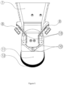
- It is a cross-sectional view of the flow adjustment plate in the wide position.
- Figure-6:
- It is a cross-sectional view of the flow adjustment plate in the narrow position.
- In order to facilitate understanding, identical reference numbers are used to indicate identical elements in the figures, where possible. The shapes are not drawn to scale and can be simplified for clarity. It is believed that the elements and features of an application can be usefully incorporated into other applications without further explanation.
- Explanations of reference numbers shown in the drawings are given below.
- 1.
- Frame
- 2.
- Fast assembly holes
- 3.
- Piston
- 4.
- Pin
- 5.
- Material outlet wall
- 6.
- Air hose
- 7.
- Holding handle
- 8.
- Flow handle
- 9.
- Connecting element
- 10.
- Flap
- 11.
- Discharge hose
- 12.
- Discharge hose cover
- 13.
- Flow adjustment plate
- 14.
- Valve
- 15.
- Main air inlet
- 16.
- Nut
- 17.
- Mechanism fixing plate
- The preferred alternatives in this detailed description of the embodiment of the granular product discharge flap (10) system for dosing systems of the present invention are only intended for providing a better understanding of the subject matter and should not be construed in any restrictive sense.
- The granular product discharge flap (10) system for dosing systems of the present invention consists of a finished frame (1) enabling product entry and exit and allowing the mechanical parts to be positioned thereon. This frame (1) is the main element of the invention where other elements are connected. This frame (1) is preferably made of conductive plastic. On the frame (1), a holding handle (7) is found, ensuring a safe manual grip of the product during assembly and disassembly. There are fast assembly holes (2) on the frame (1), enabling the assembly of the product by sliding. Under the fast assembly holes (2), a piston (3) is located to provide the motion needed for opening and closing the flap (10) on the frame (1). A connecting element (9) connects the piston (3) and the flaps (10). This connecting element (9) ensures the connection between the piston (3) and the flap (10) with a pin (4).
Figure 1 andFigure 2 present perspective views of the present invention. - Underneath the system, a material outlet wall (5) is placed to prevent the material exiting the system from being spilled and scattered around. Nuts (16) are employed to fix the material outlet walls (5) and the flaps (10) onto the frame (1). The invention comprises a valve (14) enabling opening and closing the piston (3), an air hose (6) ensuring the airflow between the valve (14) and the piston (3), and a main air inlet (15) allowing the entry of the air required by the system therein.
- The system of the present invention has flaps (10) starting and stopping the material flow by opening and closing. These flaps (10) are preferably made of stainless steel. The operating speed and modus operandi of the flaps are of utmost significance. The flaps (10) are connected to the frame (1) at two separate force points with the help of the nuts (16).
Figure 3 shows a view of the flaps (10) in the open position whileFigure 4 is a view of the flaps (10) in the closed position. In this system, adjusting the flow area inside the system during the raw material flow is highly important. In the invention, a flow handle (8) is employed to adjust the relevant flow area. The flow handle (8) is connected to the frame (1) with a mechanism fixing plate (17). These flow handles (8) provide the movement of a flow adjustment plate (13) located in the interior of the flaps (10), thereby enabling narrowing and expanding the flow area.Figure 5 andFigure 6 are cross- sectional views of the flow adjustment plate (13) in the wide and narrow positions. Accordingly, the flow area can be adjusted thanks to the flow handles (8) and the flow adjustment plate (13), without the need for any assembly and disassembly procedures. The flaps (10) and the flow adjustment plates (13) enable the invention to discharge products at fine doses and adjustable flow areas. - Discharge hose (11) is included to fully expel the raw material from the system. This discharge hose (11) is preferably made of conductive plastic. On the discharge hose (11), a discharge hose cover (12) that can be manually opened and closed is located. The discharge hose cover (12) also is preferably made of conductive plastic.
Claims (1)
- A granular product discharge flap system which is employed in dosing systems, enables discharging very fine doses of the relevant materials, and reduces assembly and disassembly times in cases of repair and maintenance requiring intervention in the system, comprising:a finished frame (1) enabling product entry and exit, allowing the mechanical parts to be positioned thereon, and being preferably made of conductive plastic;flaps (10) starting and stopping the material flow by opening and closing, wherein the flaps are preferably made of stainless steel; apiston (3) providing the motion needed for opening and closing the flaps (10); a connecting element (9) connecting the piston (3) and the flaps (10); a pin (4) ensuring the connection between the piston (3) and the connecting element (9); a material outlet wall (5) preventing the exiting material from being spilled around; a holding handle (7) allowing to hold the product during assembly and disassembly; a valve (14) enabling opening and closing the piston (3); an air hose (6) ensuring an airflow between the valve (14) and the piston (3);a main air inlet (15) allowing the entry of the air required by the system therein; nuts (16) fixing the material outlet wall (5) and the flaps (10) onto the frame (1); and characterized in that it comprises: fast assembly holes (2) enabling the assembly of the product by sliding; a flow handle (8) enabling to adjust the relevant flow area;a discharge hose (11) allowing to fully expel the raw material from the system and being preferably made of conductive plastic;a discharge hose cover (12) ensuring manual opening and closing of the discharge hose (11) and being preferably made of conductive plastic;a flow adjustment plate (13) being located in the interior of the flaps (10) and enabling narrowing and expanding the flow area with the help of the flow handle (8);a mechanism fixing plate (17) enabling connecting the flow handle (8) to the frame (1).
Applications Claiming Priority (2)
| Application Number | Priority Date | Filing Date | Title |
|---|---|---|---|
| TR2021/016062A TR2021016062A2 (en) | 2021-10-14 | 2021-10-14 | GRANULAR PRODUCT DISCHARGE VALVE SYSTEM FOR DOSING SYSTEMS |
| PCT/TR2021/051112 WO2021257043A2 (en) | 2021-10-14 | 2021-11-02 | Granular product discharge flap system for dosing systems |
Publications (4)
| Publication Number | Publication Date |
|---|---|
| EP4114558A2 EP4114558A2 (en) | 2023-01-11 |
| EP4114558A4 EP4114558A4 (en) | 2024-05-01 |
| EP4114558C0 EP4114558C0 (en) | 2025-03-26 |
| EP4114558B1 true EP4114558B1 (en) | 2025-03-26 |
Family
ID=84046278
Family Applications (1)
| Application Number | Title | Priority Date | Filing Date |
|---|---|---|---|
| EP21825695.6A Active EP4114558B1 (en) | 2021-10-14 | 2021-11-02 | Granular product discharge flap system for dosing systems |
Country Status (4)
| Country | Link |
|---|---|
| US (1) | US20240359149A1 (en) |
| EP (1) | EP4114558B1 (en) |
| TR (1) | TR2021016062A2 (en) |
| WO (1) | WO2021257043A2 (en) |
Families Citing this family (1)
| Publication number | Priority date | Publication date | Assignee | Title |
|---|---|---|---|---|
| CN117699514B (en) * | 2023-12-18 | 2024-08-06 | 阿尔法(江苏)重工科技有限公司 | Weighing device for uniform feeding of raw coal conveying system |
Family Cites Families (8)
| Publication number | Priority date | Publication date | Assignee | Title |
|---|---|---|---|---|
| US1618190A (en) * | 1923-03-21 | 1927-02-22 | Harry E Harkin | Automatic culinary machine |
| US3998426A (en) | 1975-07-10 | 1976-12-21 | Thomas John Isbester | Clamshell-type hydraulic flow control gate |
| ITVR20020028A1 (en) * | 2002-03-28 | 2003-09-29 | Moretto Plastics Automation Sr | GRAVIMETRIC DOSING EQUIPMENT AND MIXING OF GRANULAR PRODUCTS |
| US7137729B2 (en) * | 2002-03-28 | 2006-11-21 | Moretto S.P.A. | Gravimetric dosing and mixing apparatus for a plurality granular products |
| US6969044B2 (en) | 2003-12-05 | 2005-11-29 | Delzer Wayne M | Apparatus for controlling a fluid discharge |
| AT512387B1 (en) * | 2012-10-11 | 2013-08-15 | Wittmann Kunststoffgeraete | Device for dosing bulk material |
| DE102013110991B3 (en) * | 2013-10-02 | 2014-11-13 | Lemken Gmbh & Co. Kg | Dosing system of an agricultural distribution machine |
| EP2980334B1 (en) * | 2014-07-28 | 2018-08-29 | Obrist Baugeräte AG | Crane silo for the transport and the processing of bulk construction material |
-
2021
- 2021-10-14 TR TR2021/016062A patent/TR2021016062A2/en unknown
- 2021-11-02 US US18/565,081 patent/US20240359149A1/en active Pending
- 2021-11-02 WO PCT/TR2021/051112 patent/WO2021257043A2/en not_active Ceased
- 2021-11-02 EP EP21825695.6A patent/EP4114558B1/en active Active
Also Published As
| Publication number | Publication date |
|---|---|
| TR2021016062A2 (en) | 2021-10-21 |
| EP4114558A2 (en) | 2023-01-11 |
| EP4114558C0 (en) | 2025-03-26 |
| WO2021257043A3 (en) | 2022-08-04 |
| US20240359149A1 (en) | 2024-10-31 |
| WO2021257043A2 (en) | 2021-12-23 |
| EP4114558A4 (en) | 2024-05-01 |
Similar Documents
| Publication | Publication Date | Title |
|---|---|---|
| US10646842B2 (en) | Blender | |
| US9650162B2 (en) | Device for metering bulk material, in particular plastics granulate | |
| WO2012004803A1 (en) | Programmable logic controller based sugar conveying, pulverizing and dosing system | |
| EP3574811A1 (en) | Apparatus for loading a portafilter of an espresso coffee machine with a dose of ground coffee having a predetermined weight and composed of different types of coffee, according to a given recipe | |
| CN110697100B (en) | Straight-drop multi-component material unloading device controller | |
| CN209027658U (en) | A kind of burden balance bucket device | |
| US5697523A (en) | Container with a flexible internal member and multiple outlets for weighing bulk material | |
| EP0181738B1 (en) | Flow control apparatus | |
| RU2146220C1 (en) | Microweigher | |
| JP2898403B2 (en) | Micro metering device | |
| US20240359149A1 (en) | Granular product discharge flap system for dosing systems | |
| CN114534547A (en) | Powder mixer for a system for continuously processing powder products | |
| EP2454009B1 (en) | Mixer-dryer | |
| CN214268034U (en) | Grain delivery machine device and micro-scale system | |
| US2754996A (en) | Automatic batch dispensing apparatus | |
| CA2163683A1 (en) | Container with a flexible internal member | |
| CN209442306U (en) | A kind of macromolecule Weighing charging gear | |
| CN210453248U (en) | Double-door concrete aggregate feeding device | |
| CN213862754U (en) | Weighing device and micro-scale system | |
| KR102895340B1 (en) | Automatic mixing device for raw materials for cookies | |
| KR102751810B1 (en) | Material supply appararus for packing | |
| CN215661192U (en) | Full-automatic material mixing system | |
| CN208583298U (en) | A kind of feed proportioning system | |
| CN106314885A (en) | Automatic weighing system for formula materials | |
| IES85744Y1 (en) | Improvements relating to blenders |
Legal Events
| Date | Code | Title | Description |
|---|---|---|---|
| STAA | Information on the status of an ep patent application or granted ep patent |
Free format text: STATUS: THE INTERNATIONAL PUBLICATION HAS BEEN MADE |
|
| PUAI | Public reference made under article 153(3) epc to a published international application that has entered the european phase |
Free format text: ORIGINAL CODE: 0009012 |
|
| STAA | Information on the status of an ep patent application or granted ep patent |
Free format text: STATUS: REQUEST FOR EXAMINATION WAS MADE |
|
| 17P | Request for examination filed |
Effective date: 20221007 |
|
| AK | Designated contracting states |
Kind code of ref document: A2 Designated state(s): AL AT BE BG CH CY CZ DE DK EE ES FI FR GB GR HR HU IE IS IT LI LT LU LV MC MK MT NL NO PL PT RO RS SE SI SK SM TR |
|
| A4 | Supplementary search report drawn up and despatched |
Effective date: 20240403 |
|
| RIC1 | Information provided on ipc code assigned before grant |
Ipc: B65D 88/54 20060101ALN20240326BHEP Ipc: B65B 1/30 20060101ALN20240326BHEP Ipc: B01F 35/80 20220101ALN20240326BHEP Ipc: G01F 13/00 20060101ALN20240326BHEP Ipc: B01F 35/88 20220101ALI20240326BHEP Ipc: B65D 90/62 20060101ALI20240326BHEP Ipc: B65D 83/06 20060101ALI20240326BHEP Ipc: B01F 25/00 20220101AFI20240326BHEP |
|
| GRAP | Despatch of communication of intention to grant a patent |
Free format text: ORIGINAL CODE: EPIDOSNIGR1 |
|
| STAA | Information on the status of an ep patent application or granted ep patent |
Free format text: STATUS: GRANT OF PATENT IS INTENDED |
|
| DAV | Request for validation of the european patent (deleted) | ||
| DAX | Request for extension of the european patent (deleted) | ||
| RIC1 | Information provided on ipc code assigned before grant |
Ipc: B65D 88/54 20060101ALN20241218BHEP Ipc: B65B 1/30 20060101ALN20241218BHEP Ipc: B01F 35/80 20220101ALN20241218BHEP Ipc: G01F 13/00 20060101ALN20241218BHEP Ipc: B01F 35/88 20220101ALI20241218BHEP Ipc: B65D 90/62 20060101ALI20241218BHEP Ipc: B65D 83/06 20060101ALI20241218BHEP Ipc: B01F 25/00 20220101AFI20241218BHEP |
|
| GRAS | Grant fee paid |
Free format text: ORIGINAL CODE: EPIDOSNIGR3 |
|
| INTG | Intention to grant announced |
Effective date: 20250117 |
|
| GRAA | (expected) grant |
Free format text: ORIGINAL CODE: 0009210 |
|
| STAA | Information on the status of an ep patent application or granted ep patent |
Free format text: STATUS: THE PATENT HAS BEEN GRANTED |
|
| AK | Designated contracting states |
Kind code of ref document: B1 Designated state(s): AL AT BE BG CH CY CZ DE DK EE ES FI FR GB GR HR HU IE IS IT LI LT LU LV MC MK MT NL NO PL PT RO RS SE SI SK SM TR |
|
| REG | Reference to a national code |
Ref country code: GB Ref legal event code: FG4D |
|
| REG | Reference to a national code |
Ref country code: CH Ref legal event code: EP |
|
| REG | Reference to a national code |
Ref country code: DE Ref legal event code: R096 Ref document number: 602021028243 Country of ref document: DE |
|
| REG | Reference to a national code |
Ref country code: IE Ref legal event code: FG4D |
|
| U01 | Request for unitary effect filed |
Effective date: 20250418 |
|
| U07 | Unitary effect registered |
Designated state(s): AT BE BG DE DK EE FI FR IT LT LU LV MT NL PT RO SE SI Effective date: 20250428 |
|
| RAP4 | Party data changed (patent owner data changed or rights of a patent transferred) |
Owner name: GENCLER ELEKTRONIK SANAYI VE TICARET LIMITEDSIRKETI |
|
| U1H | Name or address of the proprietor changed after the registration of the unitary effect |
Owner name: GENCLER ELEKTRONIK SANAYI VE TICARET LIMITEDSIRKETI; TR |
|
| PG25 | Lapsed in a contracting state [announced via postgrant information from national office to epo] |
Ref country code: RS Free format text: LAPSE BECAUSE OF FAILURE TO SUBMIT A TRANSLATION OF THE DESCRIPTION OR TO PAY THE FEE WITHIN THE PRESCRIBED TIME-LIMIT Effective date: 20250626 |
|
| PG25 | Lapsed in a contracting state [announced via postgrant information from national office to epo] |
Ref country code: NO Free format text: LAPSE BECAUSE OF FAILURE TO SUBMIT A TRANSLATION OF THE DESCRIPTION OR TO PAY THE FEE WITHIN THE PRESCRIBED TIME-LIMIT Effective date: 20250626 |
|
| PG25 | Lapsed in a contracting state [announced via postgrant information from national office to epo] |
Ref country code: HR Free format text: LAPSE BECAUSE OF FAILURE TO SUBMIT A TRANSLATION OF THE DESCRIPTION OR TO PAY THE FEE WITHIN THE PRESCRIBED TIME-LIMIT Effective date: 20250326 |
|
| PG25 | Lapsed in a contracting state [announced via postgrant information from national office to epo] |
Ref country code: GR Free format text: LAPSE BECAUSE OF FAILURE TO SUBMIT A TRANSLATION OF THE DESCRIPTION OR TO PAY THE FEE WITHIN THE PRESCRIBED TIME-LIMIT Effective date: 20250627 |
|
| PG25 | Lapsed in a contracting state [announced via postgrant information from national office to epo] |
Ref country code: SM Free format text: LAPSE BECAUSE OF FAILURE TO SUBMIT A TRANSLATION OF THE DESCRIPTION OR TO PAY THE FEE WITHIN THE PRESCRIBED TIME-LIMIT Effective date: 20250326 |
|
| PG25 | Lapsed in a contracting state [announced via postgrant information from national office to epo] |
Ref country code: ES Free format text: LAPSE BECAUSE OF FAILURE TO SUBMIT A TRANSLATION OF THE DESCRIPTION OR TO PAY THE FEE WITHIN THE PRESCRIBED TIME-LIMIT Effective date: 20250326 |
|
| PG25 | Lapsed in a contracting state [announced via postgrant information from national office to epo] |
Ref country code: PL Free format text: LAPSE BECAUSE OF FAILURE TO SUBMIT A TRANSLATION OF THE DESCRIPTION OR TO PAY THE FEE WITHIN THE PRESCRIBED TIME-LIMIT Effective date: 20250326 |
|
| PG25 | Lapsed in a contracting state [announced via postgrant information from national office to epo] |
Ref country code: SK Free format text: LAPSE BECAUSE OF FAILURE TO SUBMIT A TRANSLATION OF THE DESCRIPTION OR TO PAY THE FEE WITHIN THE PRESCRIBED TIME-LIMIT Effective date: 20250326 |
|
| PG25 | Lapsed in a contracting state [announced via postgrant information from national office to epo] |
Ref country code: IS Free format text: LAPSE BECAUSE OF FAILURE TO SUBMIT A TRANSLATION OF THE DESCRIPTION OR TO PAY THE FEE WITHIN THE PRESCRIBED TIME-LIMIT Effective date: 20250726 |
|
| U20 | Renewal fee for the european patent with unitary effect paid |
Year of fee payment: 5 Effective date: 20250922 |
|
| PG25 | Lapsed in a contracting state [announced via postgrant information from national office to epo] |
Ref country code: CZ Free format text: LAPSE BECAUSE OF FAILURE TO SUBMIT A TRANSLATION OF THE DESCRIPTION OR TO PAY THE FEE WITHIN THE PRESCRIBED TIME-LIMIT Effective date: 20250326 |
|
| PLBE | No opposition filed within time limit |
Free format text: ORIGINAL CODE: 0009261 |
|
| STAA | Information on the status of an ep patent application or granted ep patent |
Free format text: STATUS: NO OPPOSITION FILED WITHIN TIME LIMIT |
|
| REG | Reference to a national code |
Ref country code: CH Ref legal event code: L10 Free format text: ST27 STATUS EVENT CODE: U-0-0-L10-L00 (AS PROVIDED BY THE NATIONAL OFFICE) Effective date: 20260211 |
|
| 26N | No opposition filed |
Effective date: 20260105 |