EP4114268B1 - An x-ray sensor - Google Patents
An x-ray sensor Download PDFInfo
- Publication number
- EP4114268B1 EP4114268B1 EP21711368.7A EP21711368A EP4114268B1 EP 4114268 B1 EP4114268 B1 EP 4114268B1 EP 21711368 A EP21711368 A EP 21711368A EP 4114268 B1 EP4114268 B1 EP 4114268B1
- Authority
- EP
- European Patent Office
- Prior art keywords
- ray
- sensor
- ray sensor
- rays
- processor
- Prior art date
- Legal status (The legal status is an assumption and is not a legal conclusion. Google has not performed a legal analysis and makes no representation as to the accuracy of the status listed.)
- Active
Links
Images



Classifications
-
- A—HUMAN NECESSITIES
- A61—MEDICAL OR VETERINARY SCIENCE; HYGIENE
- A61B—DIAGNOSIS; SURGERY; IDENTIFICATION
- A61B6/00—Apparatus or devices for radiation diagnosis; Apparatus or devices for radiation diagnosis combined with radiation therapy equipment
- A61B6/02—Arrangements for diagnosis sequentially in different planes; Stereoscopic radiation diagnosis
- A61B6/025—Tomosynthesis
-
- A—HUMAN NECESSITIES
- A61—MEDICAL OR VETERINARY SCIENCE; HYGIENE
- A61B—DIAGNOSIS; SURGERY; IDENTIFICATION
- A61B6/00—Apparatus or devices for radiation diagnosis; Apparatus or devices for radiation diagnosis combined with radiation therapy equipment
- A61B6/42—Arrangements for detecting radiation specially adapted for radiation diagnosis
- A61B6/4208—Arrangements for detecting radiation specially adapted for radiation diagnosis characterised by using a particular type of detector
- A61B6/4233—Arrangements for detecting radiation specially adapted for radiation diagnosis characterised by using a particular type of detector using matrix detectors
-
- A—HUMAN NECESSITIES
- A61—MEDICAL OR VETERINARY SCIENCE; HYGIENE
- A61B—DIAGNOSIS; SURGERY; IDENTIFICATION
- A61B6/00—Apparatus or devices for radiation diagnosis; Apparatus or devices for radiation diagnosis combined with radiation therapy equipment
- A61B6/42—Arrangements for detecting radiation specially adapted for radiation diagnosis
- A61B6/4208—Arrangements for detecting radiation specially adapted for radiation diagnosis characterised by using a particular type of detector
- A61B6/425—Arrangements for detecting radiation specially adapted for radiation diagnosis characterised by using a particular type of detector using detectors specially adapted to be used in the interior of the body
-
- A—HUMAN NECESSITIES
- A61—MEDICAL OR VETERINARY SCIENCE; HYGIENE
- A61B—DIAGNOSIS; SURGERY; IDENTIFICATION
- A61B6/00—Apparatus or devices for radiation diagnosis; Apparatus or devices for radiation diagnosis combined with radiation therapy equipment
- A61B6/44—Constructional features of apparatus for radiation diagnosis
- A61B6/4429—Constructional features of apparatus for radiation diagnosis related to the mounting of source units and detector units
-
- A—HUMAN NECESSITIES
- A61—MEDICAL OR VETERINARY SCIENCE; HYGIENE
- A61B—DIAGNOSIS; SURGERY; IDENTIFICATION
- A61B6/00—Apparatus or devices for radiation diagnosis; Apparatus or devices for radiation diagnosis combined with radiation therapy equipment
- A61B6/50—Apparatus or devices for radiation diagnosis; Apparatus or devices for radiation diagnosis combined with radiation therapy equipment specially adapted for specific body parts; specially adapted for specific clinical applications
- A61B6/51—Apparatus or devices for radiation diagnosis; Apparatus or devices for radiation diagnosis combined with radiation therapy equipment specially adapted for specific body parts; specially adapted for specific clinical applications for dentistry
-
- A—HUMAN NECESSITIES
- A61—MEDICAL OR VETERINARY SCIENCE; HYGIENE
- A61B—DIAGNOSIS; SURGERY; IDENTIFICATION
- A61B6/00—Apparatus or devices for radiation diagnosis; Apparatus or devices for radiation diagnosis combined with radiation therapy equipment
- A61B6/50—Apparatus or devices for radiation diagnosis; Apparatus or devices for radiation diagnosis combined with radiation therapy equipment specially adapted for specific body parts; specially adapted for specific clinical applications
- A61B6/51—Apparatus or devices for radiation diagnosis; Apparatus or devices for radiation diagnosis combined with radiation therapy equipment specially adapted for specific body parts; specially adapted for specific clinical applications for dentistry
- A61B6/512—Intraoral means
-
- A—HUMAN NECESSITIES
- A61—MEDICAL OR VETERINARY SCIENCE; HYGIENE
- A61B—DIAGNOSIS; SURGERY; IDENTIFICATION
- A61B6/00—Apparatus or devices for radiation diagnosis; Apparatus or devices for radiation diagnosis combined with radiation therapy equipment
- A61B6/52—Devices using data or image processing specially adapted for radiation diagnosis
- A61B6/5258—Devices using data or image processing specially adapted for radiation diagnosis involving detection or reduction of artifacts or noise
- A61B6/5264—Devices using data or image processing specially adapted for radiation diagnosis involving detection or reduction of artifacts or noise due to motion
-
- A—HUMAN NECESSITIES
- A61—MEDICAL OR VETERINARY SCIENCE; HYGIENE
- A61B—DIAGNOSIS; SURGERY; IDENTIFICATION
- A61B6/00—Apparatus or devices for radiation diagnosis; Apparatus or devices for radiation diagnosis combined with radiation therapy equipment
- A61B6/52—Devices using data or image processing specially adapted for radiation diagnosis
- A61B6/5258—Devices using data or image processing specially adapted for radiation diagnosis involving detection or reduction of artifacts or noise
- A61B6/5264—Devices using data or image processing specially adapted for radiation diagnosis involving detection or reduction of artifacts or noise due to motion
- A61B6/527—Devices using data or image processing specially adapted for radiation diagnosis involving detection or reduction of artifacts or noise due to motion using data from a motion artifact sensor
-
- A—HUMAN NECESSITIES
- A61—MEDICAL OR VETERINARY SCIENCE; HYGIENE
- A61B—DIAGNOSIS; SURGERY; IDENTIFICATION
- A61B6/00—Apparatus or devices for radiation diagnosis; Apparatus or devices for radiation diagnosis combined with radiation therapy equipment
- A61B6/54—Control of apparatus or devices for radiation diagnosis
- A61B6/547—Control of apparatus or devices for radiation diagnosis involving tracking of position of the device or parts of the device
-
- A—HUMAN NECESSITIES
- A61—MEDICAL OR VETERINARY SCIENCE; HYGIENE
- A61B—DIAGNOSIS; SURGERY; IDENTIFICATION
- A61B6/00—Apparatus or devices for radiation diagnosis; Apparatus or devices for radiation diagnosis combined with radiation therapy equipment
- A61B6/56—Details of data transmission or power supply, e.g. use of slip rings
Definitions
- the present invention relates generally to an x-ray sensor and a method of producing x-ray images and finds particular, although not exclusive, utility in intraoral x-ray imaging technology.
- Digital intraoral x-ray sensors in combination with conventional x-ray sources are known for producing dental x-rays.
- This type of equipment produces low-doses of x-rays.
- the sensors typically have pixel sizes as small as 20 ⁇ 20 ⁇ m.
- the acquisition times are typically of the order of 0.1-0.2 seconds such that patient motion does not generally impact on image quality.
- the resulting images are 2-dimensional.
- US2015038840A1 discloses a portable imaging device system with a detector, in which a reconstruction processor records time stamps with the measured locations of radiation event data, which are used to correlate location adjustments, of a detector, with image data.
- the invention provides an x-ray sensor for tomosynthesis imaging, in combination with an x-ray source, the x-ray sensor comprising a digital x-ray detector, an inertial sensor, and an emitter displacement calculation unit configured to calculate the x-ray sensor positional offset information, relative to a starting position of the x-ray sensor, based on x-ray emission timing signals and data from the inertial sensor; the sensor further comprising an image reconstruction unit configured to calculate resultant x-ray images based on the detected x-rays, nominal positions of the x-ray source, and the positional offset information, using the calculated translation and rotation of the inertial sensor (R) applied as the inverse (R') to the nominal x-ray source positions and orientations for each image.
- R inertial sensor
- the x-ray sensor may be configured to be moved physically independently of one or more x-ray emitters. Alternatively, or additionally, the x-ray sensor may be configured to be moved physically independently of one or more x-ray emitter arrays.
- the inertial sensor may comprise at least one accelerometer and/or at least one gyroscope.
- the inertial sensor may be integral with the x-ray detector or may be releasably attachable thereto.
- Such inertial sensors are relatively small and low-cost. For instance, these sensors can be as small as 2 ⁇ 2 ⁇ 1mm such that they can be readily integrated into an intraoral sensor which has external dimensions of approximately 32 ⁇ 44 ⁇ 10mm.
- the inertial sensors are capable of providing a stream of accurate 3-axis acceleration & orientation data which in turn can be used to track changes in the spatial position of the inertial sensor, and thus the x-ray detectors, as each image is acquired.
- the “emitter displacement calculation unit”, or processor uses the stream of data from the inertial sensor, together with timing signals to calculate positional offset information (relative to a starting position), correcting for errors in the inertial sensor data, for each image acquisition.
- the processor may also be the "image reconstruction unit” for using the detected x-rays, the nominal positions of the x-ray sources and the positional offset information to thereby calculate the resultant x-ray images.
- the processor may be arranged to calculate a motion correction factor, to be applied to one or more x-ray images, based on the positional information. This calculation may be performed by the processor which may be synchronized with an acquisition control system and which may perform integration of the inertial sensor data together with an error correction.
- the processor may include the acquisition control system.
- the processor may be arranged to create the 2-dimensional, and/or 3-dimensional, images by taking account of changes in the relative position of the intraoral x-ray sensor during detection of x-rays.
- the displacement of the sensor during the acquisition stage may be calculated from the positional data using known methods.
- the processor may be integral with the sensor. Alternatively, the processor may be external to the sensor. Another option is that the processing is undertaken by more than one processor, being located in the sensor and external to the sensor. For instance, the emitter displacement calculation unit may be arranged onboard with the x-ray sensor, and the image reconstruction unit may be arranged external to the x-ray sensor and possibly with the acquisition control system.
- the x-ray sensor may further comprise communication means for transmitting data acquired by the detector and the positional information to the processor.
- communication means include wired and wireless equipment such as radio frequency transmitters and receivers.
- the x-ray sensor may include means for of maintaining it stationary relative to the region of interest. This may include straps, cords, and other such means which enable it to be temporarily attached, and fixed positionally relative, to a subject who/which may move during the procedure.
- the x-ray sensor may be an intraoral sensor arranged to fit within a human mouth. In this way, intraoral x-ray images may be created.
- the x-ray sensor may be sized appropriately to fit in a human mouth. For instance, it may have a maximum dimension in any one orthogonal axis of 3cm.
- the x-ray sensor may further comprise a bite bar for maintaining the detector in relatively fixed relationship to the mouth of a subject during use. Other means of maintaining it stationary relative to teeth are contemplated such as clamps, grips, and substrates including parts moulded to an approximate shape of the teeth.
- These means, such as the bite bar may be integral with the x-ray sensor or be releasably attachable. For instance, they may form part of a frame provided around all or part of the x-ray sensor. It is also contemplated that the frame may, in one example, include the inertial sensor.
- the intraoral x-ray sensor Once the intraoral x-ray sensor is positioned inside the mouth, it will not then typically move relative to the teeth during whole head motion. Therefore, any intraoral x-ray sensor motion relative to an external x-ray source will also directly apply to the teeth. For this reason, during the image creation process, the calculated translation and rotation of the sensor (R) can be applied as the inverse (R') to the nominal x-ray source position and orientation for that image. This means that the image creation process does not create an image of the teeth as they would have appeared from the sensor position if there had been no motion. Rather, the process creates an image of the teeth as they appear from the actual relative position and relative orientation. In the case of a tomosynthesis acquisition of multiple images, this positional information is integrated into the reconstruction algorithm to accurately determine the relative position of the emitter and detector for each image.
- the positional information may be used to determine the degree of motion experienced during the acquisition of each individual image.
- the processor may also be arranged to provide an indication to an operator when motion of the intraoral sensor, during use, exceeds a predetermined value.
- the processor may be arranged to automatically exclude data acquired by the detector when motion of the intraoral sensor, during use, exceeds a predetermined value.
- the intraoral x-ray sensor may further be arranged to automatically emit and detect additional x-rays to "re-scan" an area for which previous image are likely to be blurry due to this excessive motion of the patient's head.
- the x-ray sensor may be arranged in combination with one or more x-ray emitters.
- the emitters may be arranged in a panel including an array of individually energisable x-ray emitters, which may be described as a distributed array of x-ray sources.
- the use of a distributed array of x-ray sources may allow each emitter to be individually electronically triggered which may be much faster than having to physically move a single x-ray source.
- digital tomosynthesis may only cover a partial sweep.
- the x-ray sensor and its method of use may allow for stationary tomosynthesis (sDT); the partial sweep being achieved possibly without physical movement of the x-ray source; instead, possibly being achieved by triggering a series of the spatially distributed fixed sources, in the array, fired in a sequence.
- sDT stationary tomosynthesis
- the array of x-ray emitters may be a single flat panel source (FPS).
- the x-ray detector may be a flat panel x-ray detector (FPD). It is expected that in use, for the imaging of a single tooth, the FPS may remain stationary relative to the environment, and remain stationary relative to the subject, assuming the subject does not move. This may also be the case for groups of immediately adjacent teeth, assuming the detector is large enough. Since the FPS includes an array of emitters, x-rays may be emitted from various positions to create enough data to produce a 3D image. However, if a single source x-ray emitter is used then the x-ray source may have to move during the procedure if 3D images are required; however, this may not be the case if only 2D images are required.
- the invention provides a method of producing x-ray images, the method comprising the steps of fixing the position of the x-ray sensor relative to the region of interest; emitting x-rays from an x-ray source towards the x-ray sensor; operating the x-ray sensor to detect said x-rays; and processing said detected x-rays to produce images of the region of interest.
- the x-ray sensor may include a bite bar, the region of interest may include at least one tooth, and the step of fixing the position of the x-ray sensor relative to the region of interest may include placing the x-ray sensor in the mouth of a subject and the subject holding the bite bar between their teeth.
- the positional information provided by the inertial sensor may be used to determine the relative position of the x-ray source and the digital x-ray detector for each image.
- the processor may calculate a motion correction factor based on the relative position of the x-ray source and the digital x-ray detector for each image.
- the detection of said x-rays may occur without any mechanical connection between the x-ray sensor and x-ray source.
- the x-ray sensor and its method of use permit accurate post-acquisition motion compensation which does not suffer from the limitations of image-based motion compensation where displacement parallel to a central axis of the x-ray beam or rotation around that beam are relatively difficult to calculate when trying to register different 2D projection images from different positions of a 3D object. They do not require any mechanical attachment between the x-ray source and x-ray detector which in turn makes for relatively faster image acquisition and relatively greater convenience for the operator and the patient.
- Accurate motion compensation reduces or eliminates image artefacts due to motion. This may lead to a reduction in, or elimination of, misinterpretation or misdiagnosis.
- top, bottom, over, under and the like in the description and the claims are used for descriptive purposes and not necessarily for describing relative positions. It is to be understood that the terms so used are interchangeable under appropriate circumstances and that operation is capable in other orientations than described or illustrated herein.
- connection should not be interpreted as being restricted to direct connections only.
- the scope of the expression “a device A connected to a device B” should not be limited to devices or systems wherein an output of device A is directly connected to an input of device B. It means that there exists a path between an output of A and an input of B which may be a path including other devices or means.
- Connected may mean that two or more elements are either in direct physical or electrical contact, or that two or more elements are not in direct contact with each other but yet still co-operate or interact with each other. For instance, wireless connectivity is contemplated.
- Figure 1 shows a schematic side view of a set of teeth 10 being exposed to x-rays 80 being emitted by an x-ray source 70.
- the patient has an intraoral x-ray sensor 20 in their mouth.
- the sensor 20 is connected by a cable 25 to a processor 45 which in turn is connected to a display 55 by cable 47.
- the sensor 20 is adjacent two teeth 18, 19.
- the x-ray source may emit a stream of x-rays from various emitters arranged within it.
- the x-rays may pass through the teeth 18, 19 and be detected by the sensor 20.
- the detector may pass the resultant digital data to the processor 45 for processing to create 2D and/or 3D images on the display 55.
- the sensor 20 comprises the detector part 40, which is cuboid in appearance, and a relatively flat and planar "bite bar" 30 which extends perpendicularly outward from one end of the detector part 40 such that, in use, the bar may be held firmly between the patient's upper and lower teeth to thereby maintain the sensor in fixed relationship to the teeth.
- the detector part 40 includes an accelerometer 50 and gyroscope 60. It is contemplated that a processor 65 may also be included for processing some or all of the data produced by any, or all of the accelerometer 50, gyroscope 60, and x-ray detector 40.
- a cable 25 is shown for communication to an external processor 45 and/or display 55, if required.
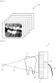
- the processor(s) 45, 65 are arranged to produce 2D and/or 3D x-ray images of the teeth which is indicated by a series of images 75 in Figure 3 .
- FIG. 4 A schematic view of a detector 40 is shown in Figure 4 .
- the detector 40 comprises a plurality of detector pixels 41, 42 etc. arranged therein for detecting x-rays.
- the accelerometer 50 is also indicated within the detector 40.
- a tooth 19 is shown being subjected to a cone shape of x-rays 80 emitted by the x-ray emitter 70.
- the cone shape of x-rays 80 meets the plurality of pixels 41, 42 in the detector 40 such that an x-ray image of the tooth may be produced once the data has been processed.
- the image may well appear similar to the one shown in Figure 6 .
- Figure 6 shows how this processing may take account of the movement of the tooth 19 and sensor 20 to create an identical, or virtually identical, image 72.
- the movement of the tooth in Figure 5 away from the previous ( Figure 4 ) position is represented by "R".
- the data is processed such that the image is created as though the x-ray emitter 70 had been moved by R' and was in the position 73, rather than its actual position 72, as shown in outline.
- the resultant image 71 is produced which can then be combined with the other images.
- Each image can be processed and adjusted such that patient movement can be compensated so that all the images are combinable as if no patient movement had occurred.
- the movement of the emitter R' and movement of the tooth R are proportional to one another, therefore, measurement of R may be used to calculate R'.
- the movement R of the tooth is determined by data sent from the accelerometer 50 and gyroscope 60, located within the sensor 20.
- step 100 the tomosynthesis acquisition controller starts operation.
- step 120 the x-ray source generates x-rays from the emitter position.
- step 130 the intraoral sensor captures the first x-ray image.
- the inertial sensor sends 105 a continuous stream of data to the emitter displacement calculator.
- the emitter displacement calculator records 115 the inertial sensor data.
- the emitter displacement calculator determines 140 displacement for each acquisition relative to the starting position.
- the emitter displacement calculator stops 150 integrating the inertial sensor data.
- the emitter displacement calculator sends 160 data to the image reconstruction unit.
- the image reconstruction unit corrects the images for apparent emitter position and generates 170 final x-ray images.
- the controller sends 180 timing signals for each subsequent x-ray emission event (for the creation of a new image).
- the x-ray sources generate 190 x-rays for every emitter position in the sequence.
- the intraoral sensor captures 200 each image in the sequence of images and sends the data to the image reconstruction unit where final x-ray images are generated 170 after having been corrected for apparent emitter position. That is, corrected for the position that x-rays are apparently emitted from.
- a plurality of emitters, or more specifically an FPS include emitters in multiple physical locations and x-rays may be emitted from apparent positions, or various combinations of, these emitters to create data to produce a 3D image.
- These various or apparent positions may be formed by energising more than one emitter synergistically.
- energising more than one emitter at the same time or with overlapping time periods is energising more than one emitter synergistically.
Landscapes
- Health & Medical Sciences (AREA)
- Life Sciences & Earth Sciences (AREA)
- Engineering & Computer Science (AREA)
- Medical Informatics (AREA)
- Physics & Mathematics (AREA)
- Biomedical Technology (AREA)
- Animal Behavior & Ethology (AREA)
- Biophysics (AREA)
- Nuclear Medicine, Radiotherapy & Molecular Imaging (AREA)
- Optics & Photonics (AREA)
- Pathology (AREA)
- Radiology & Medical Imaging (AREA)
- Veterinary Medicine (AREA)
- Heart & Thoracic Surgery (AREA)
- Molecular Biology (AREA)
- Surgery (AREA)
- High Energy & Nuclear Physics (AREA)
- General Health & Medical Sciences (AREA)
- Public Health (AREA)
- Computer Vision & Pattern Recognition (AREA)
- Dentistry (AREA)
- Oral & Maxillofacial Surgery (AREA)
- Computer Networks & Wireless Communication (AREA)
- Mathematical Physics (AREA)
- Apparatus For Radiation Diagnosis (AREA)
- Analysing Materials By The Use Of Radiation (AREA)
Description
- The present invention relates generally to an x-ray sensor and a method of producing x-ray images and finds particular, although not exclusive, utility in intraoral x-ray imaging technology.
- Digital intraoral x-ray sensors in combination with conventional x-ray sources are known for producing dental x-rays. This type of equipment produces low-doses of x-rays. The sensors typically have pixel sizes as small as 20×20µm. The acquisition times are typically of the order of 0.1-0.2 seconds such that patient motion does not generally impact on image quality. However, the resulting images are 2-dimensional.
-
US2015038840A1 discloses a portable imaging device system with a detector, in which a reconstruction processor records time stamps with the measured locations of radiation event data, which are used to correlate location adjustments, of a detector, with image data. - It is desirable to have 3-dimension images in certain circumstances. These can be produced using a combination of an array of x-ray sources in combination with an intraoral digital x-ray sensor; with the resulting data being processed to produce 3-dimension intraoral images using digital tomosynthesis. However, to achieve this, the acquisition times are typically in the range of 1-10 seconds. Consequently, patient motion impacts on the quality of the resulting images.
- This is also the case in extraoral dental x-ray procedures such as panoramic or CBCT systems where an acquisition can take between 5-40 seconds depending on the system and the protocol used.
- Further still, it is recognised that some patient motion will always occur, including head motion of perhaps 80µm due to changes in blood pressure during a cardiac cycle.
- One method to overcome this problem of patient movement is to mechanically attach the intraoral sensor to the x-ray source. However, this affects the operator's ability to position the sensor in the correct location, leading in turn to a reduction in patient comfort.
- Accordingly, it is desirable to have a system of producing dental images using an intraoral sensor and an external x-ray source, without any mechanical connection between the two, such that 3-dimensional x-ray images can be produced with relatively good clarity and lack of blurring even though the patient's head moves during the acquisition stage.
- In a first aspect, the invention provides an x-ray sensor for tomosynthesis imaging, in combination with an x-ray source, the x-ray sensor comprising a digital x-ray detector, an inertial sensor, and an emitter displacement calculation unit configured to calculate the x-ray sensor positional offset information, relative to a starting position of the x-ray sensor, based on x-ray emission timing signals and data from the inertial sensor; the sensor further comprising an image reconstruction unit configured to calculate resultant x-ray images based on the detected x-rays, nominal positions of the x-ray source, and the positional offset information, using the calculated translation and rotation of the inertial sensor (R) applied as the inverse (R') to the nominal x-ray source positions and orientations for each image.
- The x-ray sensor may be configured to be moved physically independently of one or more x-ray emitters. Alternatively, or additionally, the x-ray sensor may be configured to be moved physically independently of one or more x-ray emitter arrays.
- The inertial sensor may comprise at least one accelerometer and/or at least one gyroscope. The inertial sensor may be integral with the x-ray detector or may be releasably attachable thereto. Such inertial sensors are relatively small and low-cost. For instance, these sensors can be as small as 2×2×1mm such that they can be readily integrated into an intraoral sensor which has external dimensions of approximately 32×44×10mm.
- The inertial sensors are capable of providing a stream of accurate 3-axis acceleration & orientation data which in turn can be used to track changes in the spatial position of the inertial sensor, and thus the x-ray detectors, as each image is acquired.
- The "emitter displacement calculation unit", or processor, uses the stream of data from the inertial sensor, together with timing signals to calculate positional offset information (relative to a starting position), correcting for errors in the inertial sensor data, for each image acquisition. The processor may also be the "image reconstruction unit" for using the detected x-rays, the nominal positions of the x-ray sources and the positional offset information to thereby calculate the resultant x-ray images.
- The processor may be arranged to calculate a motion correction factor, to be applied to one or more x-ray images, based on the positional information. This calculation may be performed by the processor which may be synchronized with an acquisition control system and which may perform integration of the inertial sensor data together with an error correction.
- The processor may include the acquisition control system.
- The processor may be arranged to create the 2-dimensional, and/or 3-dimensional, images by taking account of changes in the relative position of the intraoral x-ray sensor during detection of x-rays.
- The displacement of the sensor during the acquisition stage may be calculated from the positional data using known methods.
- The processor may be integral with the sensor. Alternatively, the processor may be external to the sensor. Another option is that the processing is undertaken by more than one processor, being located in the sensor and external to the sensor. For instance, the emitter displacement calculation unit may be arranged onboard with the x-ray sensor, and the image reconstruction unit may be arranged external to the x-ray sensor and possibly with the acquisition control system.
- The x-ray sensor may further comprise communication means for transmitting data acquired by the detector and the positional information to the processor. Such communication means include wired and wireless equipment such as radio frequency transmitters and receivers.
- The x-ray sensor may include means for of maintaining it stationary relative to the region of interest. This may include straps, cords, and other such means which enable it to be temporarily attached, and fixed positionally relative, to a subject who/which may move during the procedure.
- The x-ray sensor may be an intraoral sensor arranged to fit within a human mouth. In this way, intraoral x-ray images may be created. The x-ray sensor may be sized appropriately to fit in a human mouth. For instance, it may have a maximum dimension in any one orthogonal axis of 3cm. The x-ray sensor may further comprise a bite bar for maintaining the detector in relatively fixed relationship to the mouth of a subject during use. Other means of maintaining it stationary relative to teeth are contemplated such as clamps, grips, and substrates including parts moulded to an approximate shape of the teeth. These means, such as the bite bar, may be integral with the x-ray sensor or be releasably attachable. For instance, they may form part of a frame provided around all or part of the x-ray sensor. It is also contemplated that the frame may, in one example, include the inertial sensor.
- Once the intraoral x-ray sensor is positioned inside the mouth, it will not then typically move relative to the teeth during whole head motion. Therefore, any intraoral x-ray sensor motion relative to an external x-ray source will also directly apply to the teeth. For this reason, during the image creation process, the calculated translation and rotation of the sensor (R) can be applied as the inverse (R') to the nominal x-ray source position and orientation for that image. This means that the image creation process does not create an image of the teeth as they would have appeared from the sensor position if there had been no motion. Rather, the process creates an image of the teeth as they appear from the actual relative position and relative orientation. In the case of a tomosynthesis acquisition of multiple images, this positional information is integrated into the reconstruction algorithm to accurately determine the relative position of the emitter and detector for each image.
- Furthermore, the positional information may be used to determine the degree of motion experienced during the acquisition of each individual image. The processor may also be arranged to provide an indication to an operator when motion of the intraoral sensor, during use, exceeds a predetermined value. Furthermore, the processor may be arranged to automatically exclude data acquired by the detector when motion of the intraoral sensor, during use, exceeds a predetermined value. The intraoral x-ray sensor may further be arranged to automatically emit and detect additional x-rays to "re-scan" an area for which previous image are likely to be blurry due to this excessive motion of the patient's head.
- The above discussion concerning the calculated translation and rotation of the x-ray sensor, the determination of the degree of motion experienced during the acquisition of each individual image, and the provision of an indication to an operator, may also apply to x-ray sensors, not being intraoral x-ray sensors, which are placed externally of the subject during use.
- The x-ray sensor may be arranged in combination with one or more x-ray emitters. The emitters may be arranged in a panel including an array of individually energisable x-ray emitters, which may be described as a distributed array of x-ray sources. The use of a distributed array of x-ray sources may allow each emitter to be individually electronically triggered which may be much faster than having to physically move a single x-ray source.
- Unlike CBCT, where x-rays may be emitted over a complete 360-degree sweep around the patient, digital tomosynthesis may only cover a partial sweep. The x-ray sensor and its method of use may allow for stationary tomosynthesis (sDT); the partial sweep being achieved possibly without physical movement of the x-ray source; instead, possibly being achieved by triggering a series of the spatially distributed fixed sources, in the array, fired in a sequence.
- The array of x-ray emitters may be a single flat panel source (FPS). The x-ray detector may be a flat panel x-ray detector (FPD). It is expected that in use, for the imaging of a single tooth, the FPS may remain stationary relative to the environment, and remain stationary relative to the subject, assuming the subject does not move. This may also be the case for groups of immediately adjacent teeth, assuming the detector is large enough. Since the FPS includes an array of emitters, x-rays may be emitted from various positions to create enough data to produce a 3D image. However, if a single source x-ray emitter is used then the x-ray source may have to move during the procedure if 3D images are required; however, this may not be the case if only 2D images are required.
- In a second aspect, the invention provides a method of producing x-ray images, the method comprising the steps of fixing the position of the x-ray sensor relative to the region of interest; emitting x-rays from an x-ray source towards the x-ray sensor; operating the x-ray sensor to detect said x-rays; and processing said detected x-rays to produce images of the region of interest.
- The x-ray sensor may include a bite bar, the region of interest may include at least one tooth, and the step of fixing the position of the x-ray sensor relative to the region of interest may include placing the x-ray sensor in the mouth of a subject and the subject holding the bite bar between their teeth.
- The positional information provided by the inertial sensor may be used to determine the relative position of the x-ray source and the digital x-ray detector for each image.
- The processor may calculate a motion correction factor based on the relative position of the x-ray source and the digital x-ray detector for each image.
- The detection of said x-rays may occur without any mechanical connection between the x-ray sensor and x-ray source.
- The x-ray sensor and its method of use permit accurate post-acquisition motion compensation which does not suffer from the limitations of image-based motion compensation where displacement parallel to a central axis of the x-ray beam or rotation around that beam are relatively difficult to calculate when trying to register different 2D projection images from different positions of a 3D object. They do not require any mechanical attachment between the x-ray source and x-ray detector which in turn makes for relatively faster image acquisition and relatively greater convenience for the operator and the patient.
- Accurate motion compensation reduces or eliminates image artefacts due to motion. This may lead to a reduction in, or elimination of, misinterpretation or misdiagnosis.
- Further processing of resulting images may also be undertaken based on presently known image analysis and image-based motion compensation to provide even finer levels of motion compensation.
- The above and other characteristics, features and advantages of the present invention will become apparent from the following detailed description, taken in conjunction with the accompanying drawings, which illustrate, by way of example, the principles of the invention in relation to intraoral x-ray imaging. This description is given for the sake of example only, without limiting the scope of the invention. The reference figures quoted below refer to the attached drawings.
-
Figure 1 is a schematic view of an intraoral x-ray sensor inside a patient's mouth being exposed to x-rays; -
Figure 2 is a perspective view of an intraoral x-ray sensor; -
Figure 3 is a representation of a series of x-ray images for use in creating a 3D digital tomosynthesis image; -
Figure 4 is a schematic view of a tooth being x-rayed; -
Figures 5 and 6 are schematic views of a tooth being x-rayed before and after movement of the patient; and -
Figure 7 is a flow chart depicting a method of operation of an x-ray sensor and subsequent image generation. - The present invention will be described with respect to certain drawings but the invention is not limited thereto but only by the claims. The drawings described are only schematic and are non-limiting. Each drawing may not include all of the features of the invention and therefore should not necessarily be considered to be an embodiment of the invention. In the drawings, the size of some of the elements may be exaggerated and not drawn to scale for illustrative purposes. The dimensions and the relative dimensions do not correspond to actual reductions to practice of the invention.
- Furthermore, the terms first, second, third and the like in the description and in the claims, are used for distinguishing between similar elements and not necessarily for describing a sequence, either temporally, spatially, in ranking or in any other manner. It is to be understood that the terms so used are interchangeable under appropriate circumstances and that operation is capable in other sequences than described or illustrated herein. Likewise, method steps described or claimed in a particular sequence may be understood to operate in a different sequence.
- Moreover, the terms top, bottom, over, under and the like in the description and the claims are used for descriptive purposes and not necessarily for describing relative positions. It is to be understood that the terms so used are interchangeable under appropriate circumstances and that operation is capable in other orientations than described or illustrated herein.
- It is to be noticed that the term "comprising", used in the claims, should not be interpreted as being restricted to the means listed thereafter; it does not exclude other elements or steps. It is thus to be interpreted as specifying the presence of the stated features, integers, steps or components as referred to, but does not preclude the presence or addition of one or more other features, integers, steps or components, or groups thereof. Thus, the scope of the expression "a device comprising means A and B" should not be limited to devices consisting only of components A and B. It means that with respect to the present invention, the only relevant components of the device are A and B.
- Similarly, it is to be noticed that the term "connected", used in the description, should not be interpreted as being restricted to direct connections only. Thus, the scope of the expression "a device A connected to a device B" should not be limited to devices or systems wherein an output of device A is directly connected to an input of device B. It means that there exists a path between an output of A and an input of B which may be a path including other devices or means. "Connected" may mean that two or more elements are either in direct physical or electrical contact, or that two or more elements are not in direct contact with each other but yet still co-operate or interact with each other. For instance, wireless connectivity is contemplated.
- Reference throughout this specification to "an embodiment" or "an aspect" means that a particular feature, structure or characteristic described in connection with the embodiment or aspect is included in at least one embodiment or aspect of the present invention. Thus, appearances of the phrases "in one embodiment", "in an embodiment", or "in an aspect" in various places throughout this specification are not necessarily all referring to the same embodiment or aspect, but may refer to different embodiments or aspects. Furthermore, the particular features, structures or characteristics of any one embodiment or aspect of the invention may be combined in any suitable manner with any other particular feature, structure or characteristic of another embodiment or aspect of the invention, as would be apparent to one of ordinary skill in the art from this disclosure, in one or more embodiments or aspects.
- Similarly, it should be appreciated that in the description various features of the invention are sometimes grouped together in a single embodiment, figure, or description thereof for the purpose of streamlining the disclosure and aiding in the understanding of one or more of the various inventive aspects. This method of disclosure, however, is not to be interpreted as reflecting an intention that the claimed invention requires more features than are expressly recited in each claim. Moreover, the description of any individual drawing or aspect should not necessarily be considered to be an embodiment of the invention. Rather, as the following claims reflect, inventive aspects lie in fewer than all features of a single foregoing disclosed embodiment. Thus, the claims following the detailed description are hereby expressly incorporated into this detailed description, with each claim standing on its own as a separate embodiment of this invention.
- Furthermore, while some embodiments described herein include some features included in other embodiments, combinations of features of different embodiments are meant to be within the scope of the invention, and form yet further embodiments, as will be understood by those skilled in the art. For example, in the following claims, any of the claimed embodiments can be used in any combination.
- In the description provided herein, numerous specific details are set forth. However, it is understood that embodiments of the invention may be practised without these specific details. In other instances, well-known methods, structures and techniques have not been shown in detail in order not to obscure an understanding of this description.
- In the discussion of the invention, unless stated to the contrary, the disclosure of alternative values for the upper or lower limit of the permitted range of a parameter, coupled with an indication that one of said values is more highly preferred than the other, is to be construed as an implied statement that each intermediate value of said parameter, lying between the more preferred and the less preferred of said alternatives, is itself preferred to said less preferred value and also to each value lying between said less preferred value and said intermediate value.
- The use of the term "at least one" may mean only one in certain circumstances. The use of the term "any" may mean "all" and/or "each" in certain circumstances.
- The principles of the invention will now be described by a detailed description of at least one drawing relating to exemplary features. It is clear that other arrangements can be configured according to the knowledge of persons skilled in the art without departing from the underlying concept or technical teaching, the invention being limited only by the terms of the appended claims.
-
Figure 1 shows a schematic side view of a set ofteeth 10 being exposed tox-rays 80 being emitted by anx-ray source 70. The patient has anintraoral x-ray sensor 20 in their mouth. Thesensor 20 is connected by acable 25 to aprocessor 45 which in turn is connected to adisplay 55 bycable 47. - The
sensor 20 is adjacent twoteeth teeth sensor 20. The detector may pass the resultant digital data to theprocessor 45 for processing to create 2D and/or 3D images on thedisplay 55. - An example of how an
intraoral sensor 20 may appear is shown inFigure 2 . Thesensor 20 comprises thedetector part 40, which is cuboid in appearance, and a relatively flat and planar "bite bar" 30 which extends perpendicularly outward from one end of thedetector part 40 such that, in use, the bar may be held firmly between the patient's upper and lower teeth to thereby maintain the sensor in fixed relationship to the teeth. - The
detector part 40 includes anaccelerometer 50 andgyroscope 60. It is contemplated that a processor 65 may also be included for processing some or all of the data produced by any, or all of theaccelerometer 50,gyroscope 60, andx-ray detector 40. - A
cable 25 is shown for communication to anexternal processor 45 and/ordisplay 55, if required. - The processor(s) 45, 65 are arranged to produce 2D and/or 3D x-ray images of the teeth which is indicated by a series of
images 75 inFigure 3 . - A schematic view of a
detector 40 is shown inFigure 4 . Thedetector 40 comprises a plurality ofdetector pixels - The
accelerometer 50 is also indicated within thedetector 40. - A
tooth 19 is shown being subjected to a cone shape ofx-rays 80 emitted by thex-ray emitter 70. The cone shape ofx-rays 80 meets the plurality ofpixels detector 40 such that an x-ray image of the tooth may be produced once the data has been processed. The image may well appear similar to the one shown inFigure 6 . - In
Figure 5 , thesame tooth 19 has been rotated slightly due to patient movement. Thenew position 92 is contrasted with theprevious position 90 shown in broken lines. Due to the bite bar holding thesensor 20 fixed relative to the teeth it can be seen how the sensor has also moved; its previous position also being shown in broken lines. If the image received by thedetector 40, as a result of the x-rays emitted byx-ray emitter 70, were to be combined with images taken with the tooth not having been moved, such as shown inFigure 4 , the resulting 3D image would be incorrect. This is because although the tooth and detector have moved, the x-ray emitter has remained stationary. Accordingly, the image needs to be processed to provide an image which can be combined with theFigure 4 image. -
Figure 6 shows how this processing may take account of the movement of thetooth 19 andsensor 20 to create an identical, or virtually identical,image 72. The movement of the tooth inFigure 5 away from the previous (Figure 4 ) position is represented by "R". InFigure 6 , the data is processed such that the image is created as though thex-ray emitter 70 had been moved by R' and was in theposition 73, rather than itsactual position 72, as shown in outline. Theresultant image 71 is produced which can then be combined with the other images. Each image can be processed and adjusted such that patient movement can be compensated so that all the images are combinable as if no patient movement had occurred. The movement of the emitter R' and movement of the tooth R are proportional to one another, therefore, measurement of R may be used to calculate R'. - The movement R of the tooth is determined by data sent from the
accelerometer 50 andgyroscope 60, located within thesensor 20. - In
Figure 7 , a method of operation is depicted. Instep 100 the tomosynthesis acquisition controller starts operation. The controller sends 110 a start signal (t=0) for the first x-ray emission. Instep 120, the x-ray source generates x-rays from the emitter position. Instep 130, the intraoral sensor captures the first x-ray image. Simultaneously with the emitters emitting x-rays the inertial sensor sends 105 a continuous stream of data to the emitter displacement calculator. The emitterdisplacement calculator records 115 the inertial sensor data. The emitter displacement calculator determines 140 displacement for each acquisition relative to the starting position. The emitter displacement calculator stops 150 integrating the inertial sensor data. The emitter displacement calculator sends 160 data to the image reconstruction unit. The image reconstruction unit corrects the images for apparent emitter position and generates 170 final x-ray images. - The controller sends 180 timing signals for each subsequent x-ray emission event (for the creation of a new image). The x-ray sources generate 190 x-rays for every emitter position in the sequence. The intraoral sensor captures 200 each image in the sequence of images and sends the data to the image reconstruction unit where final x-ray images are generated 170 after having been corrected for apparent emitter position. That is, corrected for the position that x-rays are apparently emitted from. For example, a plurality of emitters, or more specifically an FPS, include emitters in multiple physical locations and x-rays may be emitted from apparent positions, or various combinations of, these emitters to create data to produce a 3D image. These various or apparent positions may be formed by energising more than one emitter synergistically. By way of example, energising more than one emitter at the same time or with overlapping time periods is energising more than one emitter synergistically.
- It is to be understood that it may not be necessary to know the absolute position of the x-ray emitter relative to any fixed datum forming part of the patient, or outside the patient, since it is only the changes in position of the patient relative to a starting point that matter. However, if desired, a starting position could be recorded such that movement of the sensor relative to that position may be calculated.
- In the foregoing, the use of the singular "tooth" may include the plural "teeth" and vice-versa.
Claims (13)
- An x-ray sensor (20) for acquiring images for tomosynthesis imaging, the x-ray sensor being for use in combination with an x-ray source (70) adapted to emit x-rays, the x-ray sensor comprising a digital x-ray detector (40), an inertial sensor, and an emitter displacement calculation unit configured to calculate the x-ray sensor positional offset information, relative to a starting position of the x-ray sensor, based on x-ray emission timing signals and data from the inertial sensor; the sensor further comprising an image reconstruction unit configured to calculate resultant x-ray images (71) based on the detected x-rays, nominal positions of the x-ray source, and the positional offset information, using the calculated translation and rotation of the inertial sensor applied as the inverse to the nominal x-ray source positions and orientations for each acquired image.
- The x-ray sensor of claim 1, wherein the inertial sensor comprises at least one accelerometer (50) and/or at least one gyroscope (60).
- The x-ray sensor of either one of claims 1 and 2, wherein the emitter displacement calculation unit is a processor and is integral with the sensor.
- The x-ray sensor of either one of claims 1 and 2, wherein the emitter displacement calculation unit is a processor.
- The x-ray sensor of either one of claims 3 and 4, further comprising communication means for transmitting data acquired by the x-ray detector and the positional information to the processor.
- The x-ray sensor of any one of claims 3 to 5, wherein the processor is arranged to provide an indication to an operator when motion of the inertial sensor, during use, exceeds a predetermined value.
- The x-ray sensor of any one of claims 3 to 6, wherein the processor is arranged to automatically exclude data acquired by the x-ray detector when motion of the inertial sensor, during use, exceeds a predetermined value.
- The x-ray sensor of any preceding claim, comprising a distributed array of x-ray sources, wherein each x-ray source is configured to be individually triggered electronically.
- The x-ray sensor of any preceding claim, being an intraoral sensor arranged to fit within a human mouth.
- The x-ray sensor of claim 9, further comprising a bite bar for maintaining the x-ray detector in relatively fixed relationship to the mouth of a subject during use.
- The x-ray sensor of any preceding claim, wherein the inertial sensor is configured to be moved physically independently of the x-ray source.
- A method of producing x-ray images, the method comprising the steps of providing an x-ray sensor according to any preceding claim; fixing the position of the x-ray detector relative to a region of interest; emitting x-rays from an x-ray source towards the x-ray sensor; operating the x-ray sensor to detect said x-rays; and processing said detected x-rays to produce images of the region of interest.
- The method of claim 12, wherein the x-ray detector includes a bite bar, the region of interest includes at least one tooth, and the step of fixing the position of the x-ray sensor relative to the region of interest includes placing the x-ray sensor in the mouth of a subject and the subject holding the bite bar between their teeth.
Applications Claiming Priority (2)
| Application Number | Priority Date | Filing Date | Title |
|---|---|---|---|
| GB2002989.8A GB2592594A (en) | 2020-03-02 | 2020-03-02 | An x-ray sensor |
| PCT/IB2021/051735 WO2021176355A1 (en) | 2020-03-02 | 2021-03-02 | An x-ray sensor |
Publications (3)
| Publication Number | Publication Date |
|---|---|
| EP4114268A1 EP4114268A1 (en) | 2023-01-11 |
| EP4114268C0 EP4114268C0 (en) | 2024-12-04 |
| EP4114268B1 true EP4114268B1 (en) | 2024-12-04 |
Family
ID=70278701
Family Applications (1)
| Application Number | Title | Priority Date | Filing Date |
|---|---|---|---|
| EP21711368.7A Active EP4114268B1 (en) | 2020-03-02 | 2021-03-02 | An x-ray sensor |
Country Status (10)
| Country | Link |
|---|---|
| US (1) | US12193865B2 (en) |
| EP (1) | EP4114268B1 (en) |
| JP (1) | JP2023516662A (en) |
| KR (1) | KR20220148873A (en) |
| CN (1) | CN115209809A (en) |
| AU (1) | AU2021232135A1 (en) |
| CA (1) | CA3172366A1 (en) |
| ES (1) | ES2999863T3 (en) |
| GB (1) | GB2592594A (en) |
| WO (1) | WO2021176355A1 (en) |
Families Citing this family (3)
| Publication number | Priority date | Publication date | Assignee | Title |
|---|---|---|---|---|
| CN115299980B (en) * | 2022-08-26 | 2026-03-10 | 江苏康众数字医疗科技股份有限公司 | Oral cavity detection equipment |
| KR102838398B1 (en) * | 2023-02-08 | 2025-07-24 | 주식회사 바텍 | Position Sensing Apparatus And X-ray Imaging System Using The Same |
| CN117598718B (en) * | 2024-01-17 | 2024-04-12 | 南京瑞德医疗科技有限公司 | Camera movement detection device for CBCT and control method thereof |
Family Cites Families (20)
| Publication number | Priority date | Publication date | Assignee | Title |
|---|---|---|---|---|
| US6461040B1 (en) | 1998-11-12 | 2002-10-08 | Koninklijke Philips Electronics N.V. | Apparatus and method to correct for position errors in diagnostic imaging |
| US7775713B2 (en) * | 2005-05-16 | 2010-08-17 | Palodex Group Oy | Arrangement for dental imaging |
| JP2008253569A (en) * | 2007-04-05 | 2008-10-23 | Rigaku Corp | Abnormal body motion detection device and abnormal body motion detection method |
| JP2010179094A (en) * | 2009-01-08 | 2010-08-19 | Fujifilm Corp | Radiation tomographic image generator |
| US8559596B2 (en) * | 2010-06-08 | 2013-10-15 | Accuray Incorporated | Target Tracking for image-guided radiation treatment |
| JP5878121B2 (en) * | 2010-07-13 | 2016-03-08 | 株式会社テレシステムズ | X-ray tomography system |
| US8536547B2 (en) | 2011-01-20 | 2013-09-17 | Accuray Incorporated | Ring gantry radiation treatment delivery system with dynamically controllable inward extension of treatment head |
| FI123713B (en) | 2011-03-21 | 2013-09-30 | Planmeca Oy | Arrangements in connection with intraoral X-rays |
| WO2013144781A2 (en) * | 2012-03-30 | 2013-10-03 | Koninklijke Philips N.V. | Portable medical imager with gui interface |
| US8948482B2 (en) * | 2012-11-01 | 2015-02-03 | Align Technology, Inc. | Motion compensation in a three dimensional scan |
| US9986964B2 (en) | 2015-03-10 | 2018-06-05 | Dental Imaging Technologies Corporation | Intraoral sensor position detection for full mouth image |
| EP3235430B1 (en) | 2016-04-19 | 2019-06-12 | Agfa Nv | Radiation image capturing system and method |
| CN109803586B (en) * | 2016-05-09 | 2023-04-28 | 新维沃有限公司 | Static intraoral tomosynthesis imaging system, method and computer readable medium for three-dimensional dental imaging |
| CA3031504C (en) * | 2016-07-26 | 2023-07-11 | Dentsply Sirona Inc. | Dental x-ray sensor holder |
| US10299742B2 (en) * | 2016-09-14 | 2019-05-28 | Dental Imaging Technologies Corporation | Multiple-dimension imaging sensor with fault condition detection |
| WO2019040056A1 (en) * | 2017-08-23 | 2019-02-28 | Carestream Dental Technology Topco Limited | Dental chair-side tomosynthesis system |
| JP2019180941A (en) * | 2018-04-12 | 2019-10-24 | キヤノンメディカルシステムズ株式会社 | X-ray diagnostic apparatus, image processing apparatus, image processing system, image processing program, radiodiagnostic apparatus, and data structure of reconstruction data |
| EP3673810B1 (en) * | 2018-12-28 | 2023-09-27 | Sirona Dental Systems GmbH | Dental x-ray imaging system for producing intraoral x-ray images |
| WO2020185823A1 (en) * | 2019-03-12 | 2020-09-17 | Carestream Dental Llc | Movable and static collimators and x-ray source arrangements for intraoral tomosynthesis |
| GB2585702A (en) * | 2019-07-12 | 2021-01-20 | Adaptix Ltd | A method of obtaining x-ray images |
-
2020
- 2020-03-02 GB GB2002989.8A patent/GB2592594A/en not_active Withdrawn
-
2021
- 2021-03-02 EP EP21711368.7A patent/EP4114268B1/en active Active
- 2021-03-02 JP JP2022552589A patent/JP2023516662A/en active Pending
- 2021-03-02 WO PCT/IB2021/051735 patent/WO2021176355A1/en not_active Ceased
- 2021-03-02 CN CN202180018644.1A patent/CN115209809A/en active Pending
- 2021-03-02 CA CA3172366A patent/CA3172366A1/en active Pending
- 2021-03-02 AU AU2021232135A patent/AU2021232135A1/en active Pending
- 2021-03-02 ES ES21711368T patent/ES2999863T3/en active Active
- 2021-03-02 KR KR1020227033920A patent/KR20220148873A/en active Pending
-
2022
- 2022-09-02 US US17/902,343 patent/US12193865B2/en active Active
Also Published As
| Publication number | Publication date |
|---|---|
| EP4114268C0 (en) | 2024-12-04 |
| KR20220148873A (en) | 2022-11-07 |
| AU2021232135A1 (en) | 2022-09-15 |
| CA3172366A1 (en) | 2021-09-10 |
| US12193865B2 (en) | 2025-01-14 |
| CN115209809A (en) | 2022-10-18 |
| GB202002989D0 (en) | 2020-04-15 |
| EP4114268A1 (en) | 2023-01-11 |
| JP2023516662A (en) | 2023-04-20 |
| WO2021176355A1 (en) | 2021-09-10 |
| ES2999863T3 (en) | 2025-02-27 |
| GB2592594A (en) | 2021-09-08 |
| US20220409157A1 (en) | 2022-12-29 |
Similar Documents
| Publication | Publication Date | Title |
|---|---|---|
| US12193865B2 (en) | X-ray sensor | |
| US6878941B2 (en) | Gamma camera and CT system | |
| KR101606165B1 (en) | 3 method for producing a dental 3d xray image and xray device therefor | |
| US7844092B2 (en) | Method and system for automatic intra-oral sensor locating for image acquisition | |
| US6841782B1 (en) | Gamma camera and CT system | |
| JP3785576B2 (en) | Subject blur correction means and medical X-ray imaging apparatus using the same | |
| EP3672490B1 (en) | Dental chair-side tomosynthesis system | |
| EP3453332B1 (en) | Mobile x-ray imaging with detector docking within a spatially registered compartment | |
| KR102712709B1 (en) | X-ray imaging unit for a x-ray imaging | |
| US11903753B2 (en) | Dental x-ray imaging system for producing intraoral x-ray images | |
| JPH1052426A (en) | Radiological diagnostic apparatus for performing panoramic tomography and operation method thereof | |
| JP2001299737A (en) | Modification of data aquisition using conventional ct for better reconstitution | |
| KR20120126588A (en) | X-ray Imaging System | |
| JP4429709B2 (en) | X-ray tomography equipment | |
| JP2005204810A (en) | X-ray imaging device | |
| EP3817662B1 (en) | A method of obtaining x-ray images | |
| JP2008148964A (en) | Composite apparatus for radiotherapy and data acquisition system for alignment correction | |
| KR102838398B1 (en) | Position Sensing Apparatus And X-ray Imaging System Using The Same | |
| US20250288197A1 (en) | Data recording device | |
| JP2005253572A (en) | Image processing apparatus, X-ray diagnostic apparatus, medical image information system, and calibration table-attached method | |
| JP2672896B2 (en) | X-ray imaging device | |
| JP2002119505A (en) | X-ray CT system | |
| JP2005066144A (en) | X-ray imaging device | |
| DiFilippo et al. | Wireless Synchronization of a Multi-Pinhole Small Animal SPECT Collimation Device With a Clinical Scanner | |
| HK1019039A (en) | A method and apparatus for recording a three-dimensional image of a body part |
Legal Events
| Date | Code | Title | Description |
|---|---|---|---|
| STAA | Information on the status of an ep patent application or granted ep patent |
Free format text: STATUS: UNKNOWN |
|
| STAA | Information on the status of an ep patent application or granted ep patent |
Free format text: STATUS: THE INTERNATIONAL PUBLICATION HAS BEEN MADE |
|
| PUAI | Public reference made under article 153(3) epc to a published international application that has entered the european phase |
Free format text: ORIGINAL CODE: 0009012 |
|
| STAA | Information on the status of an ep patent application or granted ep patent |
Free format text: STATUS: REQUEST FOR EXAMINATION WAS MADE |
|
| 17P | Request for examination filed |
Effective date: 20220907 |
|
| AK | Designated contracting states |
Kind code of ref document: A1 Designated state(s): AL AT BE BG CH CY CZ DE DK EE ES FI FR GB GR HR HU IE IS IT LI LT LU LV MC MK MT NL NO PL PT RO RS SE SI SK SM TR |
|
| DAV | Request for validation of the european patent (deleted) | ||
| DAX | Request for extension of the european patent (deleted) | ||
| P01 | Opt-out of the competence of the unified patent court (upc) registered |
Effective date: 20230607 |
|
| STAA | Information on the status of an ep patent application or granted ep patent |
Free format text: STATUS: EXAMINATION IS IN PROGRESS |
|
| 17Q | First examination report despatched |
Effective date: 20231220 |
|
| REG | Reference to a national code |
Ref country code: DE Ref legal event code: R079 Free format text: PREVIOUS MAIN CLASS: A61B0006140000 Ipc: A61B0006420000 Ref country code: DE Ref legal event code: R079 Ref document number: 602021022836 Country of ref document: DE Free format text: PREVIOUS MAIN CLASS: A61B0006140000 Ipc: A61B0006420000 |
|
| GRAP | Despatch of communication of intention to grant a patent |
Free format text: ORIGINAL CODE: EPIDOSNIGR1 |
|
| STAA | Information on the status of an ep patent application or granted ep patent |
Free format text: STATUS: GRANT OF PATENT IS INTENDED |
|
| RIC1 | Information provided on ipc code assigned before grant |
Ipc: A61B 6/00 20060101ALI20240704BHEP Ipc: A61B 6/51 20240101ALI20240704BHEP Ipc: A61B 6/42 20240101AFI20240704BHEP |
|
| INTG | Intention to grant announced |
Effective date: 20240715 |
|
| RIN1 | Information on inventor provided before grant (corrected) |
Inventor name: MUGHAL, SAMI Inventor name: DIRCKX, CONRAD |
|
| GRAS | Grant fee paid |
Free format text: ORIGINAL CODE: EPIDOSNIGR3 |
|
| GRAA | (expected) grant |
Free format text: ORIGINAL CODE: 0009210 |
|
| STAA | Information on the status of an ep patent application or granted ep patent |
Free format text: STATUS: THE PATENT HAS BEEN GRANTED |
|
| AK | Designated contracting states |
Kind code of ref document: B1 Designated state(s): AL AT BE BG CH CY CZ DE DK EE ES FI FR GB GR HR HU IE IS IT LI LT LU LV MC MK MT NL NO PL PT RO RS SE SI SK SM TR |
|
| REG | Reference to a national code |
Ref country code: CH Ref legal event code: EP |
|
| REG | Reference to a national code |
Ref country code: DE Ref legal event code: R096 Ref document number: 602021022836 Country of ref document: DE |
|
| REG | Reference to a national code |
Ref country code: IE Ref legal event code: FG4D |
|
| U01 | Request for unitary effect filed |
Effective date: 20241217 |
|
| P04 | Withdrawal of opt-out of the competence of the unified patent court (upc) registered |
Free format text: CASE NUMBER: APP_649/2025 Effective date: 20250108 |
|
| U07 | Unitary effect registered |
Designated state(s): AT BE BG DE DK EE FI FR IT LT LU LV MT NL PT RO SE SI Effective date: 20250110 |
|
| REG | Reference to a national code |
Ref country code: ES Ref legal event code: FG2A Ref document number: 2999863 Country of ref document: ES Kind code of ref document: T3 Effective date: 20250227 |
|
| U20 | Renewal fee for the european patent with unitary effect paid |
Year of fee payment: 5 Effective date: 20250214 |
|
| PG25 | Lapsed in a contracting state [announced via postgrant information from national office to epo] |
Ref country code: HR Free format text: LAPSE BECAUSE OF FAILURE TO SUBMIT A TRANSLATION OF THE DESCRIPTION OR TO PAY THE FEE WITHIN THE PRESCRIBED TIME-LIMIT Effective date: 20241204 |
|
| PG25 | Lapsed in a contracting state [announced via postgrant information from national office to epo] |
Ref country code: NO Free format text: LAPSE BECAUSE OF FAILURE TO SUBMIT A TRANSLATION OF THE DESCRIPTION OR TO PAY THE FEE WITHIN THE PRESCRIBED TIME-LIMIT Effective date: 20250304 |
|
| PG25 | Lapsed in a contracting state [announced via postgrant information from national office to epo] |
Ref country code: GR Free format text: LAPSE BECAUSE OF FAILURE TO SUBMIT A TRANSLATION OF THE DESCRIPTION OR TO PAY THE FEE WITHIN THE PRESCRIBED TIME-LIMIT Effective date: 20250305 |
|
| PG25 | Lapsed in a contracting state [announced via postgrant information from national office to epo] |
Ref country code: RS Free format text: LAPSE BECAUSE OF FAILURE TO SUBMIT A TRANSLATION OF THE DESCRIPTION OR TO PAY THE FEE WITHIN THE PRESCRIBED TIME-LIMIT Effective date: 20250304 |
|
| PG25 | Lapsed in a contracting state [announced via postgrant information from national office to epo] |
Ref country code: SM Free format text: LAPSE BECAUSE OF FAILURE TO SUBMIT A TRANSLATION OF THE DESCRIPTION OR TO PAY THE FEE WITHIN THE PRESCRIBED TIME-LIMIT Effective date: 20241204 |
|
| PG25 | Lapsed in a contracting state [announced via postgrant information from national office to epo] |
Ref country code: PL Free format text: LAPSE BECAUSE OF FAILURE TO SUBMIT A TRANSLATION OF THE DESCRIPTION OR TO PAY THE FEE WITHIN THE PRESCRIBED TIME-LIMIT Effective date: 20241204 |
|
| PGFP | Annual fee paid to national office [announced via postgrant information from national office to epo] |
Ref country code: ES Payment date: 20250429 Year of fee payment: 5 |
|
| PG25 | Lapsed in a contracting state [announced via postgrant information from national office to epo] |
Ref country code: IS Free format text: LAPSE BECAUSE OF FAILURE TO SUBMIT A TRANSLATION OF THE DESCRIPTION OR TO PAY THE FEE WITHIN THE PRESCRIBED TIME-LIMIT Effective date: 20250404 |
|
| PGFP | Annual fee paid to national office [announced via postgrant information from national office to epo] |
Ref country code: CH Payment date: 20250401 Year of fee payment: 5 |
|
| PG25 | Lapsed in a contracting state [announced via postgrant information from national office to epo] |
Ref country code: SK Free format text: LAPSE BECAUSE OF FAILURE TO SUBMIT A TRANSLATION OF THE DESCRIPTION OR TO PAY THE FEE WITHIN THE PRESCRIBED TIME-LIMIT Effective date: 20241204 |
|
| PG25 | Lapsed in a contracting state [announced via postgrant information from national office to epo] |
Ref country code: CZ Free format text: LAPSE BECAUSE OF FAILURE TO SUBMIT A TRANSLATION OF THE DESCRIPTION OR TO PAY THE FEE WITHIN THE PRESCRIBED TIME-LIMIT Effective date: 20241204 |
|
| PLBE | No opposition filed within time limit |
Free format text: ORIGINAL CODE: 0009261 |
|
| STAA | Information on the status of an ep patent application or granted ep patent |
Free format text: STATUS: NO OPPOSITION FILED WITHIN TIME LIMIT |
|
| PG25 | Lapsed in a contracting state [announced via postgrant information from national office to epo] |
Ref country code: MC Free format text: LAPSE BECAUSE OF FAILURE TO SUBMIT A TRANSLATION OF THE DESCRIPTION OR TO PAY THE FEE WITHIN THE PRESCRIBED TIME-LIMIT Effective date: 20241204 |
|
| REG | Reference to a national code |
Ref country code: CH Ref legal event code: L10 Free format text: ST27 STATUS EVENT CODE: U-0-0-L10-L00 (AS PROVIDED BY THE NATIONAL OFFICE) Effective date: 20251015 |
|
| 26N | No opposition filed |
Effective date: 20250905 |
|
| PG25 | Lapsed in a contracting state [announced via postgrant information from national office to epo] |
Ref country code: IE Free format text: LAPSE BECAUSE OF NON-PAYMENT OF DUE FEES Effective date: 20250302 |
|
| REG | Reference to a national code |
Ref country code: CH Ref legal event code: U11 Free format text: ST27 STATUS EVENT CODE: U-0-0-U10-U11 (AS PROVIDED BY THE NATIONAL OFFICE) Effective date: 20260401 |
|
| U20 | Renewal fee for the european patent with unitary effect paid |
Year of fee payment: 6 Effective date: 20260303 |
|
| PGFP | Annual fee paid to national office [announced via postgrant information from national office to epo] |
Ref country code: GB Payment date: 20260303 Year of fee payment: 6 |