EP4114156A1 - A terminal block unit for an input/output device of a modular process control system - Google Patents
A terminal block unit for an input/output device of a modular process control system Download PDFInfo
- Publication number
- EP4114156A1 EP4114156A1 EP21182384.4A EP21182384A EP4114156A1 EP 4114156 A1 EP4114156 A1 EP 4114156A1 EP 21182384 A EP21182384 A EP 21182384A EP 4114156 A1 EP4114156 A1 EP 4114156A1
- Authority
- EP
- European Patent Office
- Prior art keywords
- terminal block
- signal conditioning
- block unit
- unit
- conditioning units
- Prior art date
- Legal status (The legal status is an assumption and is not a legal conclusion. Google has not performed a legal analysis and makes no representation as to the accuracy of the status listed.)
- Granted
Links
Images

Classifications
-
- G—PHYSICS
- G05—CONTROLLING; REGULATING
- G05B—CONTROL OR REGULATING SYSTEMS IN GENERAL; FUNCTIONAL ELEMENTS OF SUCH SYSTEMS; MONITORING OR TESTING ARRANGEMENTS FOR SUCH SYSTEMS OR ELEMENTS
- G05B19/00—Program-control systems
- G05B19/02—Program-control systems electric
- G05B19/418—Total factory control, i.e. centrally controlling a plurality of machines, e.g. direct or distributed numerical control [DNC], flexible manufacturing systems [FMS], integrated manufacturing systems [IMS] or computer integrated manufacturing [CIM]
- G05B19/4185—Total factory control, i.e. centrally controlling a plurality of machines, e.g. direct or distributed numerical control [DNC], flexible manufacturing systems [FMS], integrated manufacturing systems [IMS] or computer integrated manufacturing [CIM] characterised by the network communication
-
- H—ELECTRICITY
- H01—ELECTRIC ELEMENTS
- H01R—ELECTRICALLY-CONDUCTIVE CONNECTIONS; STRUCTURAL ASSOCIATIONS OF A PLURALITY OF MUTUALLY-INSULATED ELECTRICAL CONNECTING ELEMENTS; COUPLING DEVICES; CURRENT COLLECTORS
- H01R9/00—Structural associations of a plurality of mutually-insulated electrical connecting elements, e.g. terminal strips or terminal blocks; Terminals or binding posts mounted upon a base or in a case; Bases therefor
- H01R9/22—Bases, e.g. strip, block, panel
- H01R9/24—Terminal blocks
-
- H—ELECTRICITY
- H01—ELECTRIC ELEMENTS
- H01R—ELECTRICALLY-CONDUCTIVE CONNECTIONS; STRUCTURAL ASSOCIATIONS OF A PLURALITY OF MUTUALLY-INSULATED ELECTRICAL CONNECTING ELEMENTS; COUPLING DEVICES; CURRENT COLLECTORS
- H01R13/00—Details of coupling devices of the kinds covered by groups H01R12/70 or H01R24/00 - H01R33/00
- H01R13/46—Bases; Cases
- H01R13/514—Bases; Cases composed as a modular blocks or assembly, i.e. composed of co-operating parts provided with contact members or holding contact members between them
-
- H—ELECTRICITY
- H05—ELECTRIC TECHNIQUES NOT OTHERWISE PROVIDED FOR
- H05K—PRINTED CIRCUITS; CASINGS OR CONSTRUCTIONAL DETAILS OF ELECTRIC APPARATUS; MANUFACTURE OF ASSEMBLAGES OF ELECTRICAL COMPONENTS
- H05K7/00—Constructional details common to different types of electric apparatus
- H05K7/14—Mounting supporting structure in casing or on frame or rack
- H05K7/1462—Mounting supporting structure in casing or on frame or rack for programmable logic controllers [PLC] for automation or industrial process control
- H05K7/1468—Mechanical features of input/output (I/O) modules
- H05K7/1469—Terminal blocks for connecting sensors
-
- G—PHYSICS
- G05—CONTROLLING; REGULATING
- G05B—CONTROL OR REGULATING SYSTEMS IN GENERAL; FUNCTIONAL ELEMENTS OF SUCH SYSTEMS; MONITORING OR TESTING ARRANGEMENTS FOR SUCH SYSTEMS OR ELEMENTS
- G05B2219/00—Program-control systems
- G05B2219/30—Nc systems
- G05B2219/31—From computer integrated manufacturing till monitoring
- G05B2219/31088—Network communication between supervisor and cell, machine group
Definitions
- the present invention relates to a terminal block unit for an input/output device of a modular process control system, an input/output device with such terminal block unit and a modular process control system with such an input/output device.
- Process control systems are generally known in the prior art.
- Process control systems comprise several different hardware units, for example, at least one I/O module with several signal conditioning units, a power source, a communication interface unit and a control unit.
- Process control systems are used among others to control complex production plants, e.g. in process industry or automobile industry.
- ABB Ability System 800xA Select I/O was developed by the applicant under the type designation ABB Ability System 800xA Select I/O.
- a terminal block unit for an input/output device of a modular process control system comprising:
- the terminal block unit is preferably configured to be directly housed in a pair of two adjacent slot elements of a module termination unit, i.e. no further contact elements, units, modules, etc. are arranged between the slot elements of the module termination unit and the plug/socket/connector of the terminal block unit.
- the parallel connection is provided by means of a hard wiring and/or by means of an electronic redundancy circuit comprising electronic elements, like elements for voltage, power limiting and common current shunt, or something else as fuse.
- the terminal block unit provides no direct communication channel between two redundant signal conditioning units.
- the terminal block unit comprises a redundancy contact element configured to provide a communication link between the redundant signal conditioning units.
- the generic input/output unit handles the communication between a fieldbus communication interface and the signal conditioning units.
- the generic input/output unit communicates upstream with the fieldbus communication interface using, for example, Modulebus, and downstream with up to various signal conditioning units, e.g. up to 16 signal conditioning units.
- Such generic input/output units may be used in a single or a redundant mode.
- the terminal block unit comprises only two slot elements configured to receive only the two redundant signal conditioning units.
- the terminal block unit comprises at least one blocking element configured to prohibit the insertion of certain (e.g. unsupported signal family types) signal conditioning units in the slot elements, e.g. intrinsically safe signal conditioning units, 24V signal conditioning units, high voltage signal conditioning units and/or any other signal type family, wherein the blocking element is preferably arranged at the slot elements.
- certain signal conditioning units e.g. unsupported signal family types
- the blocking element is preferably arranged at the slot elements.
- the terminal block unit comprises coding elements configured to mate with coding elements of a signal conditioning unit for determining the type of signal conditioning unit.
- the terminal block unit comprises identification elements configured to provide information to the signal conditioning unit that the terminal block unit is a redundant terminal block unit for receiving two redundant signal conditioning units.
- the terminal block unit comprises at least one probe hole for measurement purposes, e.g. for measuring voltage, signals and/or for a communication link with a handheld device for diagnose, setting, upload measurements.
- an Input/output device comprising at least one module termination unit housing at least one generic input/output unit and at least one terminal block unit as described above is provided.
- the module termination unit comprises between 8 and 32 slot elements, preferably 18 slot elements, housing two generic input/output units and providing 16 further slot elements for single termination blocks each occupying one slot element and/or (redundant) termination blocks as described above each occupying two slot elements of the module termination block.
- a modular process control system comprising at least one input/output device, wherein at least one terminal block unit as described above is housed in a module termination unit of the input/output device and wherein in the slot elements of the terminal block unit a pair of redundant signal conditioning units is housed.
- the two redundant signal conditioning units are configured to read or write a process value of a field device in parallel.
- the signal conditioning units are configured to provide an analog output, wherein both signal conditioning units share the current and drive of the total process value of the field device, wherein both signal conditioning units preferably share the current and drive 50% of the total process value of the field device.
- the signal conditioning units are configured to provide a digital output, wherein only a primary signal conditioning unit is active and a backup signal conditioning unit is continuously listening to the communication.
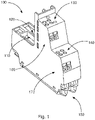
- a terminal block unit 100 for an input/output device of a modular process control system is schematically shown.
- the terminal block unit 100 comprises two input/output slot elements 110 and 120, which are configured to receive two redundant signal conditioning units ( cf. figure 2 ). Redundant signal conditioning units are preferably signal conditioning units which are identical or which at least provide the same technical function.
- the terminal block unit 100 may comprises probe holes 130, 140 for each terminal for connecting test probes for voltage measurements.
- a contact socked e.g. U-shape contact element
- the terminal block unit 100 can be housed in a pair of two adjacent slot elements of a module termination unit 300 (cf. figure 2 ).
- the terminal block unit 100 may comprise several input clamp or screw contacts 160, 170 for inputs, like a supply voltage, a ground connections, etc.
- the terminal block unit 100 may comprise a socket 150 for inserting the terminal block unit in a module termination unit 300.
- Figure 2 shows a schematic cross sectional view of an input/output device 200 comprising a module termination unit 300, at least one terminal block unit 100 as shown in figure 1 , which is housed in the module termination unit 300 and at least two redundant signal conditioning units 400, 410, which are housed in the terminal block unit 100.
- the terminal block unit 100 may also comprise a field connection 180.
- Figure 3 shows a schematic exemplary wiring diagram of redundant signal conditioning units 400, 410 housed in a terminal block unit 100 in an input/output device 200.
- an input of a primary signal conditioning unit 400 and an input of a backup signal conditioning unit 410 are connected in parallel with a process input signal 500 of a field device (not shown).
- an output of the primary signal conditioning unit 400 and an output of the backup signal conditioning unit 410 are connected in parallel with at least one generic input/output unit, wherein in the shown preferred embodiment, redundant generic input/output units 420, 430 are provided.
- the generic input/output units 420, 430 are connected via a communication link 440.
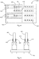
- Figure 4 shows a schematic top view of an input/output device 200 with a redundant terminal block unit 100 and a single terminal block unit 600, wherein a slot element 700 of the input/output device 200 is not used.
- a process input signal 500 of a field device (not shown) can be connected in parallel with a redundant pair of signal conditioning units 400 and 410.
- the input/output device 200 further comprises connector elements 800 to the system interface.
- the terminal block unit 100 may further comprise a redundancy contact element 190 configured to provide a communication link between the redundant signal conditioning units 400 and 410.
- FIG. 5 shows the redundancy contact element 190 and its contacts to the redundant signal conditioning units 400 and 410 in more detail.
- the PCB 401 of the primary signal conditioning unit 400 with its contact pads 402 and 403 of is shown on the left side, whereas the PCB 411 of the backup signal conditioning unit 410 with its contact pads 412 and 413 is shown on the right side.
- the redundancy contact element 190 a short circuit of the contact pad 402 to 403 or 412 to 413 allows a signal conditioning unit detection to the redundant terminal block.
- the contact may also be used to provide a communication link for the redundant signal conditioning units.
- the number of necessary contact elements in the terminal block unit may be reduces.
- no such redundancy contact element 190 is provided such that no short circuit between the contact pads 402 and 403 could indicate the single terminal unit configuration.
- the terminal block type can be chosen dependent on the requirements of the connected field device (e.g. single / redundant, IS / NonIS, 24V/120V/230V).
- Terminal blocks units and signal conditioning units that are not allowed to be combined may comprise a mechanical lock that prevents its combination.
- the different terminal blocks units may comprise a self-learning function by which the plugged signal conditioning unit may read out. This information may then propagated to the engineering tools to simplify a commissioning. For special signal types, it is also possible to add electronics into the terminal block unit.
- Two Signal conditioning units When two Signal conditioning units are expected to execute as redundant pair they have to be plugged in a redundant terminal block unit, by which they are connected to the field device in parallel. There is no direct communication channel between two redundant signal conditioning units. This reduces complexity and safes cost.
- Two redundant signal conditioning units may exchange information via the generic input/output unit(s) (cf. figure 3 ).
- the inputs of the redundant signal conditioning units read the process value in parallel.
- the outputs of the redundant signal conditioning units drive the output in parallel, wherein in case of analog output signal conditioning units both modules share the current and drive 50% of the total process value each.
- This architecture makes it possible that both primary and backup redundant signal conditioning unit have always the capability to execute all supervision. This prevents that there are any hidden errors that are first detected after a redundancy switchover.
- the terminal block unit type can be chosen depending what signal type is at hand, e.g. relays.
- Terminal block unit detection is available, since the signal conditioning unit can detect, if it is mounted in redundant or non-redundant terminal block.
- the real configuration can be read out in order to do a much easier engineering of the system.
- Backup generic input/output unit may check cyclically the communication link to both redundant signal conditioning units.
- Technical advantage is to get fast redundancy switchover.
- 50/50% output value sharing of output modules may provide the technical advantage that the value drops only by 50% in case of red switchover.
- Backup signal conditioning unit may listening to HART-Communication of the primary redundant signal conditioning unit provides the technical advantage that HART data is provided immediately after switchover.
- Both redundant signal conditioning units may generate events to not lose them during redundancy switchover.
Landscapes
- Engineering & Computer Science (AREA)
- Automation & Control Theory (AREA)
- Microelectronics & Electronic Packaging (AREA)
- General Engineering & Computer Science (AREA)
- Manufacturing & Machinery (AREA)
- Quality & Reliability (AREA)
- Physics & Mathematics (AREA)
- General Physics & Mathematics (AREA)
- Programmable Controllers (AREA)
Abstract
Description
- The present invention relates to a terminal block unit for an input/output device of a modular process control system, an input/output device with such terminal block unit and a modular process control system with such an input/output device.
- Process control systems are generally known in the prior art. Process control systems comprise several different hardware units, for example, at least one I/O module with several signal conditioning units, a power source, a communication interface unit and a control unit. Process control systems are used among others to control complex production plants, e.g. in process industry or automobile industry. For example, such a system was developed by the applicant under the type designation ABB Ability System 800xA Select I/O.
- It has now become apparent that there is a further need to provide I/O channels of an I/O module redundantly in a simple and safe way.
- In view of the above, it is an object of the present invention to provide a possibility to provide I/O channels of an I/O module redundantly in a simple and safe way. These and other objects, which become apparent upon reading the following description, are solved by the subject matter of the independent claims. The dependent claims refer to preferred embodiments of the invention.
- According to an aspect of the present disclosure, a terminal block unit for an input/output device of a modular process control system is provided, comprising:
- two slot elements configured to receive two redundant signal conditioning units;
- wherein the terminal block unit is configured to be housed in a pair of two adjacent slot elements of a module termination unit of an input/output device;
- wherein the terminal block unit provides a parallel connection of the redundant signal conditioning units to a field device.
- Notably, the terminal block unit is preferably configured to be directly housed in a pair of two adjacent slot elements of a module termination unit, i.e. no further contact elements, units, modules, etc. are arranged between the slot elements of the module termination unit and the plug/socket/connector of the terminal block unit.
- In an embodiment of the terminal block unit, the parallel connection is provided by means of a hard wiring and/or by means of an electronic redundancy circuit comprising electronic elements, like elements for voltage, power limiting and common current shunt, or something else as fuse.
- In an embodiment of the terminal block unit, the terminal block unit provides no direct communication channel between two redundant signal conditioning units.
- In an embodiment of the terminal block unit, the terminal block unit comprises a redundancy contact element configured to provide a communication link between the redundant signal conditioning units. The generic input/output unit handles the communication between a fieldbus communication interface and the signal conditioning units. The generic input/output unit communicates upstream with the fieldbus communication interface using, for example, Modulebus, and downstream with up to various signal conditioning units, e.g. up to 16 signal conditioning units. Such generic input/output units may be used in a single or a redundant mode.
- In an embodiment of the terminal block unit, the terminal block unit comprises only two slot elements configured to receive only the two redundant signal conditioning units.
- In an embodiment of the terminal block unit, the terminal block unit comprises at least one blocking element configured to prohibit the insertion of certain (e.g. unsupported signal family types) signal conditioning units in the slot elements, e.g. intrinsically safe signal conditioning units, 24V signal conditioning units, high voltage signal conditioning units and/or any other signal type family, wherein the blocking element is preferably arranged at the slot elements.
- In an embodiment of the terminal block unit, the terminal block unit comprises coding elements configured to mate with coding elements of a signal conditioning unit for determining the type of signal conditioning unit.
- In an embodiment of the terminal block unit, the terminal block unit comprises identification elements configured to provide information to the signal conditioning unit that the terminal block unit is a redundant terminal block unit for receiving two redundant signal conditioning units.
- In an embodiment of the terminal block unit, the terminal block unit comprises at least one probe hole for measurement purposes, e.g. for measuring voltage, signals and/or for a communication link with a handheld device for diagnose, setting, upload measurements.
- According to a further aspect, an Input/output device comprising at least one module termination unit housing at least one generic input/output unit and at least one terminal block unit as described above is provided.
- In an embodiment of the input/output device, the module termination unit comprises between 8 and 32 slot elements, preferably 18 slot elements, housing two generic input/output units and providing 16 further slot elements for single termination blocks each occupying one slot element and/or (redundant) termination blocks as described above each occupying two slot elements of the module termination block.
- According to a further aspect, a modular process control system is provided comprising at least one input/output device, wherein at least one terminal block unit as described above is housed in a module termination unit of the input/output device and wherein in the slot elements of the terminal block unit a pair of redundant signal conditioning units is housed.
- In an embodiment of the modular process control system, the two redundant signal conditioning units are configured to read or write a process value of a field device in parallel.
- In an embodiment of the modular process control system, the signal conditioning units are configured to provide an analog output, wherein both signal conditioning units share the current and drive of the total process value of the field device, wherein both signal conditioning units preferably share the current and drive 50% of the total process value of the field device.
- In an embodiment of the modular process control system, the signal conditioning units are configured to provide a digital output, wherein only a primary signal conditioning unit is active and a backup signal conditioning unit is continuously listening to the communication.
- In the following, the present disclosure is described exemplarily with reference to the enclosed figures, in which
- Figure 1
- shows a schematic view of a terminal block unit according to an embodiment of the present disclosure;
- Figure 2
- shows a schematic cross sectional view of input/output device according to an embodiment of the present disclosure;
- Figure 3
- shows a schematic exemplary wiring diagram of redundant signal conditioning units in an input/output device;
- Figure 4
- shows a schematic top view of an input/output device with a redundant terminal block unit and a single terminal block unit; and
- Figure 5
- shows a schematic view of a redundancy contact element.
- In
figure 1 , aterminal block unit 100 for an input/output device of a modular process control system is schematically shown. Theterminal block unit 100 comprises two input/output slot elements figure 2 ). Redundant signal conditioning units are preferably signal conditioning units which are identical or which at least provide the same technical function. Theterminal block unit 100 may comprisesprobe holes terminal block unit 100 can be housed in a pair of two adjacent slot elements of a module termination unit 300 (cf.figure 2 ). Moreover, theterminal block unit 100 may comprise several input clamp orscrew contacts terminal block unit 100 may comprise asocket 150 for inserting the terminal block unit in amodule termination unit 300. -
Figure 2 shows a schematic cross sectional view of an input/output device 200 comprising amodule termination unit 300, at least oneterminal block unit 100 as shown infigure 1 , which is housed in themodule termination unit 300 and at least two redundantsignal conditioning units terminal block unit 100. As shown infigure 2 , theterminal block unit 100 may also comprise afield connection 180. -
Figure 3 shows a schematic exemplary wiring diagram of redundantsignal conditioning units terminal block unit 100 in an input/output device 200. As shown, an input of a primarysignal conditioning unit 400 and an input of a backupsignal conditioning unit 410 are connected in parallel with aprocess input signal 500 of a field device (not shown). Moreover, also an output of the primarysignal conditioning unit 400 and an output of the backupsignal conditioning unit 410 are connected in parallel with at least one generic input/output unit, wherein in the shown preferred embodiment, redundant generic input/output units output units communication link 440. -
Figure 4 shows a schematic top view of an input/output device 200 with a redundantterminal block unit 100 and a singleterminal block unit 600, wherein aslot element 700 of the input/output device 200 is not used. As shown, aprocess input signal 500 of a field device (not shown) can be connected in parallel with a redundant pair ofsignal conditioning units output device 200 further comprisesconnector elements 800 to the system interface. As also shown infigures 4 and 5 , theterminal block unit 100 may further comprise aredundancy contact element 190 configured to provide a communication link between the redundantsignal conditioning units -
Figure 5 shows theredundancy contact element 190 and its contacts to the redundantsignal conditioning units PCB 401 of the primarysignal conditioning unit 400 with itscontact pads PCB 411 of the backupsignal conditioning unit 410 with itscontact pads contact pad 402 to 403 or 412 to 413 allows a signal conditioning unit detection to the redundant terminal block. Moreover, the contact may also be used to provide a communication link for the redundant signal conditioning units. Thus, by means of this double function the number of necessary contact elements in the terminal block unit may be reduces. At the singleterminal block unit 600, no suchredundancy contact element 190 is provided such that no short circuit between thecontact pads - In the following, a summary of the effects and advantages of the present disclosure is explained:
- For configurations where high availability is a requirement input/output channels shall be configured redundant. By means of the present disclosure, it is possible to configure redundancy on channel granular basis for safety and non-safety signals. Signals for field connections are not routed through a backplane / module termination unit (cf.
figure 2 ). This gives several technical and economic benefits. Only those input/output channels that have high requirements on availability need to be configured redundant. Other channels on same baseplate can remain in single configuration to keep high channel density and safe costs. During commissioning this gives high flexibility, it can be decided late in the project schedule whether it needs to be redundant or not. Also after several years of execution, redundancy can be added to existing channels without creating too much effort. - As there are no electrical connections between a backplane and the terminal block unit, the terminal block type can be chosen dependent on the requirements of the connected field device (e.g. single / redundant, IS / NonIS, 24V/120V/230V). Terminal blocks units and signal conditioning units that are not allowed to be combined (e.g. Non-IS SCM and IS FTB) may comprise a mechanical lock that prevents its combination. In case where multiple terminal blocks units can be used (e.g. Single / Redundant), the different terminal blocks units may comprise a self-learning function by which the plugged signal conditioning unit may read out. This information may then propagated to the engineering tools to simplify a commissioning. For special signal types, it is also possible to add electronics into the terminal block unit.
- When two Signal conditioning units are expected to execute as redundant pair they have to be plugged in a redundant terminal block unit, by which they are connected to the field device in parallel. There is no direct communication channel between two redundant signal conditioning units. This reduces complexity and safes cost. Two redundant signal conditioning units may exchange information via the generic input/output unit(s) (cf.
figure 3 ). The inputs of the redundant signal conditioning units read the process value in parallel. The outputs of the redundant signal conditioning units drive the output in parallel, wherein in case of analog output signal conditioning units both modules share the current and drive 50% of the total process value each. This architecture makes it possible that both primary and backup redundant signal conditioning unit have always the capability to execute all supervision. This prevents that there are any hidden errors that are first detected after a redundancy switchover. With analog redundant signal conditioning units which are capable to perform HART-Communication, only the primary redundant signal conditioning unit is active, however the backup redundant signal conditioning unit is continuously listening to the communication to make data available immediately after a redundancy switchover. In case the generic input/output unit is configured redundant as well, the backup generic input/output unit cyclically checks its communication link to both redundant signal conditioning units to safeguard availability after a redundancy switchover. Both primary and backup signal conditioning unit may generate alarm and events. This architecture reduces the risk that events are lost in case of a redundancy switchover. - It can per channel decided, if it shall be redundant or not and the signals to the terminals are not routed through the module terminal unit: Redundant terminal block units for safety and non-safety single channel universal input/output signals. Technical advantage: It can be defined in a very late step of the commissioning, if the channels shall be redundant or not. Flexible way for commissioning the system and easier to do late changes. After several years of runtime of a plant you can easily add redundant channels. One does not need to change the baseplate, but only the terminal block.
- The terminal block unit type can be chosen depending what signal type is at hand, e.g. relays. Technical advantage: High voltage and the terminal block unit according to the present disclosure can be used for different signals.
- Terminal block unit detection is available, since the signal conditioning unit can detect, if it is mounted in redundant or non-redundant terminal block. Technical advantage: the real configuration can be read out in order to do a much easier engineering of the system.
- An implicit information exchange without a direct redundancy link is available. Data exchange in between redundant modules without separate redundancy link, but via the generic input/output unit(s). Technical advantage: Lower hardware costs
- Backup generic input/output unit may check cyclically the communication link to both redundant signal conditioning units. Technical advantage is to get fast redundancy switchover.
- It is possible to actively test the ability to power a field device through temporarily increasing/decreasing the voltage of the backup channel compared to the active channel.
- 50/50% output value sharing of output modules may provide the technical advantage that the value drops only by 50% in case of red switchover.
- Backup signal conditioning unit may listening to HART-Communication of the primary redundant signal conditioning unit provides the technical advantage that HART data is provided immediately after switchover.
- Both redundant signal conditioning units may generate events to not lose them during redundancy switchover.
- The present disclosure has been described in conjunction with a preferred embodiment as examples as well. However, other variations can be understood and effected by those persons skilled in the art and practicing the claimed invention, from the studies of the drawings, this disclosure and the claims. Notably, in particular, the any steps presented can be performed in any order, i.e. the present invention is not limited to a specific order of these steps. Moreover, it is also not required that the different steps are performed at a certain place or at one node of a distributed system, i.e. each of the steps may be performed at a different nodes using different equipment/data processing units.
- In the claims as well as in the description the word "comprising" does not exclude other elements or steps and the indefinite article "a" or "an" does not exclude a plurality. A single element or other unit may fulfill the functions of several entities or items recited in the claims. The mere fact that certain measures are recited in the mutual different dependent claims does not indicate that a combination of these measures cannot be used in an advantageous implementation.
Claims (15)
- A terminal block unit (100) for an input/output device (200) of a modular process control system, comprising:two slot elements (110, 120) configured to receive two redundant signal conditioning units (400, 410);wherein the terminal block unit (100) is configured to be housed in a pair of two adjacent slot elements of a module termination unit (300) of an input/output device (200);wherein the terminal block unit (100) provides a parallel connection of the redundant signal conditioning units (400, 410) to a field device.
- The terminal block unit (100) according to claim 1, wherein the parallel connection for the redundant signal conditioning units (400, 410) is provided by means of a hard wiring and/or by means of an electronic redundancy circuit.
- The terminal block unit (100) according to claim 1 or claim 2, wherein the terminal block unit (100) provides no direct communication channel between two redundant signal conditioning units (400, 410).
- The terminal block unit (100) according to any one of the preceding claims, wherein the terminal block unit (100) comprises a redundancy contact element (190) configured to provide a communication link between the redundant signal conditioning units (400, 410).
- The terminal block unit (100) according to any one of the preceding claims, wherein the terminal block unit (100) comprises only two slot elements (110, 120) configured to receive only the two redundant signal conditioning units (400, 410).
- The terminal block unit (100) according to any one of the preceding claims, wherein the terminal block unit (100) comprises at least one blocking element configured to prohibit the insertion of certain signal conditioning units in the slot elements (110, 120), preferably unsupported signal family types, like intrinsically safe signal conditioning units, high voltage signal conditioning units and/or 24V signal conditioning units, wherein the blocking element is preferably arranged at the slot elements (110, 120).
- The terminal block unit (100) according to any one of the preceding claims, wherein the terminal block unit (100) comprises coding elements configured to mate with coding elements of a signal conditioning unit (400, 410) for determining the type of signal conditioning unit (400, 410).
- The terminal block unit (100) according to any one of the preceding claims, wherein the terminal block unit (100) comprises identification elements configured to provide the information to provide information to the signal conditioning unit (400, 410) that the terminal block unit (100) is a terminal block unit (100) for receiving two redundant signal conditioning units (400, 410).
- The terminal block unit (100) according to any one of the preceding claims, wherein the terminal block unit (100) comprises at least one probe hole (130, 140) for measurement purposes, like voltage measurements, signal measurements and/or for providing a communication link with a handheld device for diagnose, setting and/or upload purposes.
- An Input/output device (200) comprising at least one module termination unit (300) housing at least one generic input/output unit (420, 430) and at least one terminal block unit (100) according to any one of the preceding claims.
- The input/output device (200) according to claim 10, wherein the module termination unit (300) comprises between 8 and 32 slot elements, preferably 18 slot elements, housing two generic input/output units (420, 430), single termination blocks and/or termination blocks according to any one of the claims 1 to 9.
- A modular process control system comprising at least one input/output device (200), wherein at least one terminal block unit (100) according to any one of the claims 1 to 9 is housed in a module termination unit (300) of an input/output device (200) and wherein in the slot elements (110, 120) of a terminal block unit (100) a pair of redundant signal conditioning units (400, 410) is housed.
- The modular process control system according to claim 12, wherein the two redundant signal conditioning units (400, 410) are configured to read a process value of a field device in parallel.
- The module process control system according to claim 12 or claim 13, wherein the signal conditioning units (400, 410) are configured to provide an analog output, wherein both signal conditioning units (400, 410) share the current and drive the total process value of the field device, wherein both signal conditioning units (400, 410) preferably share the current and drive 50% of the total process value of the field device.
- The module process control system according to claim 12 or claim 13, wherein the signal conditioning units (400, 410) are configured to provide a digital output, wherein only a primary signal conditioning unit (400) is active and a backup signal conditioning unit (410) is continuously listening to the communication.
Priority Applications (3)
| Application Number | Priority Date | Filing Date | Title |
|---|---|---|---|
| EP21182384.4A EP4114156B1 (en) | 2021-06-29 | 2021-06-29 | A terminal block unit for an input/output device of a modular process control system |
| US17/851,686 US12191620B2 (en) | 2021-06-29 | 2022-06-28 | Terminal block unit for an input/output device of a modular process control system |
| CN202210751207.7A CN115542848B (en) | 2021-06-29 | 2022-06-28 | Junction box unit for input/output devices of modular process control systems |
Applications Claiming Priority (1)
| Application Number | Priority Date | Filing Date | Title |
|---|---|---|---|
| EP21182384.4A EP4114156B1 (en) | 2021-06-29 | 2021-06-29 | A terminal block unit for an input/output device of a modular process control system |
Publications (2)
| Publication Number | Publication Date |
|---|---|
| EP4114156A1 true EP4114156A1 (en) | 2023-01-04 |
| EP4114156B1 EP4114156B1 (en) | 2025-08-06 |
Family
ID=76807498
Family Applications (1)
| Application Number | Title | Priority Date | Filing Date |
|---|---|---|---|
| EP21182384.4A Active EP4114156B1 (en) | 2021-06-29 | 2021-06-29 | A terminal block unit for an input/output device of a modular process control system |
Country Status (3)
| Country | Link |
|---|---|
| US (1) | US12191620B2 (en) |
| EP (1) | EP4114156B1 (en) |
| CN (1) | CN115542848B (en) |
Families Citing this family (1)
| Publication number | Priority date | Publication date | Assignee | Title |
|---|---|---|---|---|
| EP4114156B1 (en) * | 2021-06-29 | 2025-08-06 | Abb Schweiz Ag | A terminal block unit for an input/output device of a modular process control system |
Citations (3)
| Publication number | Priority date | Publication date | Assignee | Title |
|---|---|---|---|---|
| EP2698677A1 (en) * | 2012-08-17 | 2014-02-19 | Siemens Aktiengesellschaft | Peripheral system |
| US20170344451A1 (en) * | 2016-05-31 | 2017-11-30 | Bristol, Inc. | Methods and apparatus to communicatively couple field devices to a remote terminal unit |
| US20210100124A1 (en) * | 2019-09-26 | 2021-04-01 | Rockwell Automation Technologies, Inc. | Input/output system |
Family Cites Families (40)
| Publication number | Priority date | Publication date | Assignee | Title |
|---|---|---|---|---|
| FR2502449A1 (en) * | 1981-03-23 | 1982-09-24 | Alsthom Cgee | DEVICE FOR FIXING AN APPARATUS TO SUPPORT PROFILES |
| FR2593647B1 (en) * | 1986-01-29 | 1988-03-18 | Legrand Sa | JUNCTION BLOCK TO BE REPORTED ON A PROFILE. |
| IT1244115B (en) * | 1990-11-29 | 1994-07-05 | Elcon Instr Srl | CONNECTION SYSTEM FOR INDUSTRIAL INSTRUMENTATION INSTRUMENTATION CABLES |
| US5775955A (en) * | 1996-09-17 | 1998-07-07 | Graube; Maris | Modular fieldbus terminal block |
| US6033268A (en) * | 1997-04-30 | 2000-03-07 | Westinghouse Electric Corporation | Modular I/O system with two-way connectors between units and a common lock for multiple plug-in modules |
| US6175932B1 (en) * | 1998-04-20 | 2001-01-16 | National Instruments Corporation | System and method for providing state capture and restoration to an I/O system |
| US6390890B1 (en) * | 1999-02-06 | 2002-05-21 | Charles J Molnar | Finishing semiconductor wafers with a fixed abrasive finishing element |
| DE60032595T2 (en) * | 1999-04-14 | 2007-10-04 | The Whitaker Corp., Wilmington | FASTENING DEVICE FOR MOUNTING MODULES ON A RAIL |
| US6802737B2 (en) * | 2000-09-12 | 2004-10-12 | Tyco Electronics Amp Gmbh | Modular connection system for ethernet applications in the industrial sector |
| USD472878S1 (en) * | 2000-11-16 | 2003-04-08 | Omron Corporation | Connecting terminal |
| US6811425B1 (en) * | 2003-09-25 | 2004-11-02 | Excel Cell Electronic Co., Ltd. | Controller module responsive to input signals for controlling an electrical appliance |
| DE10348088B3 (en) * | 2003-10-16 | 2005-01-20 | Moeller Gmbh | Electrical protection switch for switchgear with frame clamps fitted into side arms of 2-part housing cover for switch housing |
| US7625250B2 (en) * | 2005-05-23 | 2009-12-01 | Blackwell Donald A | Interlocking modules for high packing ratios |
| US8526185B2 (en) * | 2010-10-18 | 2013-09-03 | Cisco Technology, Inc. | Collar for electrically grounding a heat sink for a computer component |
| SG180054A1 (en) * | 2010-10-29 | 2012-05-30 | Rockwell Automation Asia Pacific Business Ctr Pte Ltd | System and method for connecting an automation controller and a programmable module |
| US8379398B2 (en) * | 2011-03-23 | 2013-02-19 | Phoenix Contact Development & Manufacturing, Inc. | DIN rail mountable base for process fieldbus redundant power conditioner |
| DE102011105157B4 (en) * | 2011-06-17 | 2019-01-03 | Phoenix Contact Gmbh & Co. Kg | Electrical connection module with interruptible circuit and method for detecting a current strength |
| DE102012010145A1 (en) * | 2012-05-24 | 2013-11-28 | Phoenix Contact Gmbh & Co. Kg | I / O Module |
| CN203386013U (en) * | 2013-06-08 | 2014-01-08 | 杭州和利时自动化有限公司 | Redundancy output device |
| DE102013111696A1 (en) * | 2013-10-23 | 2015-04-23 | Endress + Hauser Flowtec Ag | Connecting device for a field device and field device with such a connection device |
| JP5904190B2 (en) * | 2013-10-31 | 2016-04-13 | 横河電機株式会社 | I/O Module |
| DE102013112099B4 (en) * | 2013-11-04 | 2021-10-07 | Phoenix Contact Gmbh & Co. Kg | Component assembly system |
| US9325110B2 (en) * | 2014-02-27 | 2016-04-26 | Rockwell Automation Technologies, Inc. | Input/output module |
| CN104714406B (en) * | 2014-12-31 | 2017-06-09 | 重庆川仪自动化股份有限公司 | Input/output module redundancy switching method |
| DE102015104290A1 (en) * | 2015-03-23 | 2016-09-29 | Phoenix Contact Gmbh & Co. Kg | Modular bus system |
| TWI589213B (en) * | 2015-03-30 | 2017-06-21 | 台達電子工業股份有限公司 | Clip and electronic device using same |
| GB201608819D0 (en) * | 2016-05-19 | 2016-07-06 | Cooper Technologies Co | Electronic device and surge handling |
| US9966714B1 (en) * | 2017-07-05 | 2018-05-08 | Rockwell Automation Asia Pacific Business Ctr. Pte., Ltd. | I/O migration adapter for control system |
| US10483663B2 (en) * | 2017-11-09 | 2019-11-19 | Rockwell Automation Asia Pacific Business Center Pte. Ltd. | Terminal block with retention features for a removable I/O module |
| US10194553B1 (en) * | 2017-11-11 | 2019-01-29 | Rockwell Automation Asia Pacific Business Center Pte. Ltd. | Selectively installable and removable auxiliary wiring device for I/O module |
| ES2922495T3 (en) * | 2018-05-16 | 2022-09-15 | Robot S A | Building automation device for arrangement in a rail |
| US10631426B1 (en) * | 2018-09-28 | 2020-04-21 | Rockwell Automation Technologies, Inc. | Electronics module mounting system |
| US10790609B2 (en) * | 2018-10-22 | 2020-09-29 | Honeywell International Inc. | Field termination assembly supporting use of mistake-proof keys |
| JP6962309B2 (en) * | 2018-12-14 | 2021-11-05 | オムロン株式会社 | Terminal block and terminal block set |
| US10579558B1 (en) * | 2019-03-06 | 2020-03-03 | Honeywell International Inc. | Flexible redundant input/output (I/O) schemes for I/O channels |
| US10867504B2 (en) * | 2019-04-25 | 2020-12-15 | Baker Hughes Oilfield Operations Llc | Monitoring of marshalling cabinet wiring |
| US10838386B1 (en) * | 2019-09-26 | 2020-11-17 | Rockwell Automation Technologies, Inc. | Distributed modular I/O device with configurable single-channel I/O submodules |
| US11016921B2 (en) * | 2019-10-24 | 2021-05-25 | Haier Us Appliance Solutions, Inc. | Appliances and methods for off-board data storage |
| CN117083574A (en) * | 2021-03-24 | 2023-11-17 | 发那科株式会社 | Electronic equipment |
| EP4114156B1 (en) * | 2021-06-29 | 2025-08-06 | Abb Schweiz Ag | A terminal block unit for an input/output device of a modular process control system |
-
2021
- 2021-06-29 EP EP21182384.4A patent/EP4114156B1/en active Active
-
2022
- 2022-06-28 US US17/851,686 patent/US12191620B2/en active Active
- 2022-06-28 CN CN202210751207.7A patent/CN115542848B/en active Active
Patent Citations (3)
| Publication number | Priority date | Publication date | Assignee | Title |
|---|---|---|---|---|
| EP2698677A1 (en) * | 2012-08-17 | 2014-02-19 | Siemens Aktiengesellschaft | Peripheral system |
| US20170344451A1 (en) * | 2016-05-31 | 2017-11-30 | Bristol, Inc. | Methods and apparatus to communicatively couple field devices to a remote terminal unit |
| US20210100124A1 (en) * | 2019-09-26 | 2021-04-01 | Rockwell Automation Technologies, Inc. | Input/output system |
Also Published As
| Publication number | Publication date |
|---|---|
| EP4114156B1 (en) | 2025-08-06 |
| US20220416452A1 (en) | 2022-12-29 |
| CN115542848B (en) | 2026-01-09 |
| US12191620B2 (en) | 2025-01-07 |
| CN115542848A (en) | 2022-12-30 |
Similar Documents
| Publication | Publication Date | Title |
|---|---|---|
| US6275881B1 (en) | Device for inherently safe signal matching | |
| US6466539B1 (en) | Bus system | |
| US5065154A (en) | Digitally addressble electronic device with interchanged and inverted address lines | |
| US10963412B2 (en) | Flexible expandable automation device with hot-swappable I/O-units | |
| EP2421346B1 (en) | Automation control system components with electronic keying features | |
| CN102713773B (en) | Safety modules for automation devices | |
| US8156251B1 (en) | Advanced logic system | |
| US11699867B2 (en) | Removable terminal block assembly that permits an I/O base to operate in simplex mode or duplex mode | |
| US8554953B1 (en) | Advanced logic system diagnostics and monitoring | |
| CN107450486A (en) | Method and apparatus for field apparatus to be communicably coupled to remote-terminal unit | |
| US4789792A (en) | Feeding of matching circuit | |
| EP4114156B1 (en) | A terminal block unit for an input/output device of a modular process control system | |
| US10084214B2 (en) | Automatic switchover from cell voltage to interconnect voltage monitoring | |
| CN210604939U (en) | Wire harness testing device | |
| US4042832A (en) | Logic board interlock indication apparatus | |
| GB2341739A (en) | Connection integrity monitor for digital selection circuits | |
| CN109254553A (en) | Control systems of nuclear power plant | |
| US6373819B1 (en) | Routine testing parity maintenance | |
| US20170103007A1 (en) | Configurable Input/Output Sub-channels for Optimized Diagnostics | |
| CN209070330U (en) | Control systems of nuclear power plant | |
| US4320512A (en) | Monitored digital system | |
| JPS62226068A (en) | Tester | |
| RU2858460C1 (en) | Device for interfacing with relay contacts | |
| US7131028B2 (en) | System and method for interconnecting nodes of a redundant computer system | |
| RU2574837C2 (en) | Logic control system (versions) |
Legal Events
| Date | Code | Title | Description |
|---|---|---|---|
| PUAI | Public reference made under article 153(3) epc to a published international application that has entered the european phase |
Free format text: ORIGINAL CODE: 0009012 |
|
| STAA | Information on the status of an ep patent application or granted ep patent |
Free format text: STATUS: THE APPLICATION HAS BEEN PUBLISHED |
|
| AK | Designated contracting states |
Kind code of ref document: A1 Designated state(s): AL AT BE BG CH CY CZ DE DK EE ES FI FR GB GR HR HU IE IS IT LI LT LU LV MC MK MT NL NO PL PT RO RS SE SI SK SM TR |
|
| STAA | Information on the status of an ep patent application or granted ep patent |
Free format text: STATUS: REQUEST FOR EXAMINATION WAS MADE |
|
| 17P | Request for examination filed |
Effective date: 20230704 |
|
| RBV | Designated contracting states (corrected) |
Designated state(s): AL AT BE BG CH CY CZ DE DK EE ES FI FR GB GR HR HU IE IS IT LI LT LU LV MC MK MT NL NO PL PT RO RS SE SI SK SM TR |
|
| GRAP | Despatch of communication of intention to grant a patent |
Free format text: ORIGINAL CODE: EPIDOSNIGR1 |
|
| STAA | Information on the status of an ep patent application or granted ep patent |
Free format text: STATUS: GRANT OF PATENT IS INTENDED |
|
| INTG | Intention to grant announced |
Effective date: 20250312 |
|
| GRAS | Grant fee paid |
Free format text: ORIGINAL CODE: EPIDOSNIGR3 |
|
| GRAA | (expected) grant |
Free format text: ORIGINAL CODE: 0009210 |
|
| STAA | Information on the status of an ep patent application or granted ep patent |
Free format text: STATUS: THE PATENT HAS BEEN GRANTED |
|
| AK | Designated contracting states |
Kind code of ref document: B1 Designated state(s): AL AT BE BG CH CY CZ DE DK EE ES FI FR GB GR HR HU IE IS IT LI LT LU LV MC MK MT NL NO PL PT RO RS SE SI SK SM TR |
|
| REG | Reference to a national code |
Ref country code: GB Ref legal event code: FG4D |
|
| REG | Reference to a national code |
Ref country code: CH Ref legal event code: EP |
|
| REG | Reference to a national code |
Ref country code: DE Ref legal event code: R096 Ref document number: 602021035467 Country of ref document: DE |
|
| REG | Reference to a national code |
Ref country code: IE Ref legal event code: FG4D |
|
| REG | Reference to a national code |
Ref country code: NL Ref legal event code: MP Effective date: 20250806 |
|
| PG25 | Lapsed in a contracting state [announced via postgrant information from national office to epo] |
Ref country code: IS Free format text: LAPSE BECAUSE OF FAILURE TO SUBMIT A TRANSLATION OF THE DESCRIPTION OR TO PAY THE FEE WITHIN THE PRESCRIBED TIME-LIMIT Effective date: 20251206 |
|
| PG25 | Lapsed in a contracting state [announced via postgrant information from national office to epo] |
Ref country code: NO Free format text: LAPSE BECAUSE OF FAILURE TO SUBMIT A TRANSLATION OF THE DESCRIPTION OR TO PAY THE FEE WITHIN THE PRESCRIBED TIME-LIMIT Effective date: 20251106 |
|
| REG | Reference to a national code |
Ref country code: LT Ref legal event code: MG9D |
|
| PG25 | Lapsed in a contracting state [announced via postgrant information from national office to epo] |
Ref country code: PT Free format text: LAPSE BECAUSE OF FAILURE TO SUBMIT A TRANSLATION OF THE DESCRIPTION OR TO PAY THE FEE WITHIN THE PRESCRIBED TIME-LIMIT Effective date: 20251209 |
|
| PG25 | Lapsed in a contracting state [announced via postgrant information from national office to epo] |
Ref country code: FI Free format text: LAPSE BECAUSE OF FAILURE TO SUBMIT A TRANSLATION OF THE DESCRIPTION OR TO PAY THE FEE WITHIN THE PRESCRIBED TIME-LIMIT Effective date: 20250806 |
|
| PG25 | Lapsed in a contracting state [announced via postgrant information from national office to epo] |
Ref country code: NL Free format text: LAPSE BECAUSE OF FAILURE TO SUBMIT A TRANSLATION OF THE DESCRIPTION OR TO PAY THE FEE WITHIN THE PRESCRIBED TIME-LIMIT Effective date: 20250806 Ref country code: HR Free format text: LAPSE BECAUSE OF FAILURE TO SUBMIT A TRANSLATION OF THE DESCRIPTION OR TO PAY THE FEE WITHIN THE PRESCRIBED TIME-LIMIT Effective date: 20250806 |
|
| PG25 | Lapsed in a contracting state [announced via postgrant information from national office to epo] |
Ref country code: GR Free format text: LAPSE BECAUSE OF FAILURE TO SUBMIT A TRANSLATION OF THE DESCRIPTION OR TO PAY THE FEE WITHIN THE PRESCRIBED TIME-LIMIT Effective date: 20251107 |
|
| PG25 | Lapsed in a contracting state [announced via postgrant information from national office to epo] |
Ref country code: SE Free format text: LAPSE BECAUSE OF FAILURE TO SUBMIT A TRANSLATION OF THE DESCRIPTION OR TO PAY THE FEE WITHIN THE PRESCRIBED TIME-LIMIT Effective date: 20250806 |
|
| PG25 | Lapsed in a contracting state [announced via postgrant information from national office to epo] |
Ref country code: LV Free format text: LAPSE BECAUSE OF FAILURE TO SUBMIT A TRANSLATION OF THE DESCRIPTION OR TO PAY THE FEE WITHIN THE PRESCRIBED TIME-LIMIT Effective date: 20250806 |
|
| PG25 | Lapsed in a contracting state [announced via postgrant information from national office to epo] |
Ref country code: PL Free format text: LAPSE BECAUSE OF FAILURE TO SUBMIT A TRANSLATION OF THE DESCRIPTION OR TO PAY THE FEE WITHIN THE PRESCRIBED TIME-LIMIT Effective date: 20250806 Ref country code: BG Free format text: LAPSE BECAUSE OF FAILURE TO SUBMIT A TRANSLATION OF THE DESCRIPTION OR TO PAY THE FEE WITHIN THE PRESCRIBED TIME-LIMIT Effective date: 20250806 |
|
| PG25 | Lapsed in a contracting state [announced via postgrant information from national office to epo] |
Ref country code: RS Free format text: LAPSE BECAUSE OF FAILURE TO SUBMIT A TRANSLATION OF THE DESCRIPTION OR TO PAY THE FEE WITHIN THE PRESCRIBED TIME-LIMIT Effective date: 20251106 |
|
| PG25 | Lapsed in a contracting state [announced via postgrant information from national office to epo] |
Ref country code: ES Free format text: LAPSE BECAUSE OF FAILURE TO SUBMIT A TRANSLATION OF THE DESCRIPTION OR TO PAY THE FEE WITHIN THE PRESCRIBED TIME-LIMIT Effective date: 20250806 |
|
| REG | Reference to a national code |
Ref country code: AT Ref legal event code: MK05 Ref document number: 1823534 Country of ref document: AT Kind code of ref document: T Effective date: 20250806 |
|
| PG25 | Lapsed in a contracting state [announced via postgrant information from national office to epo] |
Ref country code: SM Free format text: LAPSE BECAUSE OF FAILURE TO SUBMIT A TRANSLATION OF THE DESCRIPTION OR TO PAY THE FEE WITHIN THE PRESCRIBED TIME-LIMIT Effective date: 20250806 |
|
| PG25 | Lapsed in a contracting state [announced via postgrant information from national office to epo] |
Ref country code: DK Free format text: LAPSE BECAUSE OF FAILURE TO SUBMIT A TRANSLATION OF THE DESCRIPTION OR TO PAY THE FEE WITHIN THE PRESCRIBED TIME-LIMIT Effective date: 20250806 |
|
| PG25 | Lapsed in a contracting state [announced via postgrant information from national office to epo] |
Ref country code: AT Free format text: LAPSE BECAUSE OF FAILURE TO SUBMIT A TRANSLATION OF THE DESCRIPTION OR TO PAY THE FEE WITHIN THE PRESCRIBED TIME-LIMIT Effective date: 20250806 |
|
| PG25 | Lapsed in a contracting state [announced via postgrant information from national office to epo] |
Ref country code: IT Free format text: LAPSE BECAUSE OF FAILURE TO SUBMIT A TRANSLATION OF THE DESCRIPTION OR TO PAY THE FEE WITHIN THE PRESCRIBED TIME-LIMIT Effective date: 20250806 |
|
| PG25 | Lapsed in a contracting state [announced via postgrant information from national office to epo] |
Ref country code: CZ Free format text: LAPSE BECAUSE OF FAILURE TO SUBMIT A TRANSLATION OF THE DESCRIPTION OR TO PAY THE FEE WITHIN THE PRESCRIBED TIME-LIMIT Effective date: 20250806 |
|
| PG25 | Lapsed in a contracting state [announced via postgrant information from national office to epo] |
Ref country code: EE Free format text: LAPSE BECAUSE OF FAILURE TO SUBMIT A TRANSLATION OF THE DESCRIPTION OR TO PAY THE FEE WITHIN THE PRESCRIBED TIME-LIMIT Effective date: 20250806 Ref country code: SK Free format text: LAPSE BECAUSE OF FAILURE TO SUBMIT A TRANSLATION OF THE DESCRIPTION OR TO PAY THE FEE WITHIN THE PRESCRIBED TIME-LIMIT Effective date: 20250806 |