EP4114120A1 - Method and apparatus for communication systems involving incorporating user equipment identifiers into control channel transmissions - Google Patents
Method and apparatus for communication systems involving incorporating user equipment identifiers into control channel transmissions Download PDFInfo
- Publication number
- EP4114120A1 EP4114120A1 EP21183257.1A EP21183257A EP4114120A1 EP 4114120 A1 EP4114120 A1 EP 4114120A1 EP 21183257 A EP21183257 A EP 21183257A EP 4114120 A1 EP4114120 A1 EP 4114120A1
- Authority
- EP
- European Patent Office
- Prior art keywords
- user equipment
- identifier value
- value
- identifier
- control channel
- Prior art date
- Legal status (The legal status is an assumption and is not a legal conclusion. Google has not performed a legal analysis and makes no representation as to the accuracy of the status listed.)
- Granted
Links
Images

Classifications
-
- H—ELECTRICITY
- H04—ELECTRIC COMMUNICATION TECHNIQUE
- H04W—WIRELESS COMMUNICATION NETWORKS
- H04W12/00—Security arrangements; Authentication; Protecting privacy or anonymity
- H04W12/02—Protecting privacy or anonymity, e.g. protecting personally identifiable information [PII]
-
- H—ELECTRICITY
- H04—ELECTRIC COMMUNICATION TECHNIQUE
- H04L—TRANSMISSION OF DIGITAL INFORMATION, e.g. TELEGRAPHIC COMMUNICATION
- H04L5/00—Arrangements affording multiple use of the transmission path
- H04L5/003—Arrangements for allocating sub-channels of the transmission path
- H04L5/0053—Allocation of signalling, i.e. of overhead other than pilot signals
-
- H—ELECTRICITY
- H04—ELECTRIC COMMUNICATION TECHNIQUE
- H04W—WIRELESS COMMUNICATION NETWORKS
- H04W72/00—Local resource management
- H04W72/20—Control channels or signalling for resource management
-
- H—ELECTRICITY
- H04—ELECTRIC COMMUNICATION TECHNIQUE
- H04W—WIRELESS COMMUNICATION NETWORKS
- H04W12/00—Security arrangements; Authentication; Protecting privacy or anonymity
- H04W12/03—Protecting confidentiality, e.g. by encryption
-
- H—ELECTRICITY
- H04—ELECTRIC COMMUNICATION TECHNIQUE
- H04W—WIRELESS COMMUNICATION NETWORKS
- H04W12/00—Security arrangements; Authentication; Protecting privacy or anonymity
- H04W12/04—Key management, e.g. using generic bootstrapping architecture [GBA]
-
- H—ELECTRICITY
- H04—ELECTRIC COMMUNICATION TECHNIQUE
- H04W—WIRELESS COMMUNICATION NETWORKS
- H04W12/00—Security arrangements; Authentication; Protecting privacy or anonymity
- H04W12/04—Key management, e.g. using generic bootstrapping architecture [GBA]
- H04W12/041—Key generation or derivation
-
- H—ELECTRICITY
- H04—ELECTRIC COMMUNICATION TECHNIQUE
- H04W—WIRELESS COMMUNICATION NETWORKS
- H04W12/00—Security arrangements; Authentication; Protecting privacy or anonymity
- H04W12/60—Context-dependent security
- H04W12/69—Identity-dependent
- H04W12/75—Temporary identity
-
- H—ELECTRICITY
- H04—ELECTRIC COMMUNICATION TECHNIQUE
- H04W—WIRELESS COMMUNICATION NETWORKS
- H04W28/00—Network traffic management; Network resource management
- H04W28/02—Traffic management, e.g. flow control or congestion control
- H04W28/0268—Traffic management, e.g. flow control or congestion control using specific QoS parameters for wireless networks, e.g. QoS class identifier [QCI] or guaranteed bit rate [GBR]
-
- H—ELECTRICITY
- H04—ELECTRIC COMMUNICATION TECHNIQUE
- H04W—WIRELESS COMMUNICATION NETWORKS
- H04W28/00—Network traffic management; Network resource management
- H04W28/02—Traffic management, e.g. flow control or congestion control
- H04W28/0273—Traffic management, e.g. flow control or congestion control adapting protocols for flow control or congestion control to wireless environment, e.g. adapting transmission control protocol [TCP]
-
- H—ELECTRICITY
- H04—ELECTRIC COMMUNICATION TECHNIQUE
- H04W—WIRELESS COMMUNICATION NETWORKS
- H04W74/00—Wireless channel access
- H04W74/002—Transmission of channel access control information
- H04W74/006—Transmission of channel access control information in the downlink, i.e. towards the terminal
-
- H—ELECTRICITY
- H04—ELECTRIC COMMUNICATION TECHNIQUE
- H04W—WIRELESS COMMUNICATION NETWORKS
- H04W72/00—Local resource management
- H04W72/04—Wireless resource allocation
- H04W72/044—Wireless resource allocation based on the type of the allocated resource
- H04W72/0446—Resources in time domain, e.g. slots or frames
-
- H—ELECTRICITY
- H04—ELECTRIC COMMUNICATION TECHNIQUE
- H04W—WIRELESS COMMUNICATION NETWORKS
- H04W74/00—Wireless channel access
- H04W74/08—Non-scheduled access, e.g. ALOHA
- H04W74/0833—Random access procedures, e.g. with 4-step access
-
- H—ELECTRICITY
- H04—ELECTRIC COMMUNICATION TECHNIQUE
- H04W—WIRELESS COMMUNICATION NETWORKS
- H04W8/00—Network data management
- H04W8/26—Network addressing or numbering for mobility support
-
- H—ELECTRICITY
- H04—ELECTRIC COMMUNICATION TECHNIQUE
- H04W—WIRELESS COMMUNICATION NETWORKS
- H04W92/00—Interfaces specially adapted for wireless communication networks
- H04W92/04—Interfaces between hierarchically different network devices
- H04W92/10—Interfaces between hierarchically different network devices between terminal device and access point, i.e. wireless air interface
Definitions
- the present disclosure relates to apparatus, a method, and a computer program, and in particular but not exclusively to apparatus, methods and computer programs for communication systems involving the incorporation into control channel transmissions of identifiers by which a user equipment (UE) can identify control channel transmissions specific thereto.
- UE user equipment
- Some communication systems involve a base station (e.g. eNB or gNB) making UE-specific control channel transmissions (e.g. physical downlink control channel PDCCH transmission) for a plurality of UEs.
- a control channel transmission specific to a UE may, for example, indicate the allocation of data channel resources (e.g. physical downlink shared channel PDSCH and/or physical uplink shared channel PUSCH resources) to uplink and/or downlink transmissions for the UE.
- a control channel transmission specific to a UE incorporates an identifier for the UE. The UE searches control channel transmission resources for a control channel transmission incorporating the identifier for the UE.
- a method comprising: duplicating, at a user equipment, base station computation of an identifier value for the user equipment; and searching, at the user equipment, for one or more control channel transmissions incorporating an identifier value matching the identifier value computed at the user equipment.
- Duplicating base station computation of an identifier value for the user equipment may comprise computing an identifier value based on one or more input parameter values and one or more mathematical functions used at the base station to compute an identifier value for the user equipment.
- Computation of an identifier value may be based at least partly on a value of a time-related parameter; and the computed identifier value may be effective for a time period related to the value of the time-related parameter.
- the method may further comprise: duplicating, at the user equipment, base station computation of a further identifier value; and after expiry of the time period, searching at the user equipment for one or more control channel transmissions incorporating an identifier value matching the further identifier value computed at the user equipment.
- the time-related parameter may be a system frame number.
- Computation of an identifier value may be at least partly based on a security key value derived at least partly from a secret key shared between the base station and the user equipment.
- Computation of an identifier value may be at least partly based on a start value included in a random access reply message.
- the one or more control channel transmissions may indicate radio resources allocated to the user equipment for downlink and/or uplink transmissions.
- a method comprising: duplicating, at a base station, user equipment computation of an identifier value for the user equipment; and incorporating the identifier value into one or more control channel transmissions specific to the user equipment.
- Duplicating user equipment computation of an identifier value for the user equipment may comprise computing an identifier value based on one or more input parameter values and one or more mathematical functions used at the user equipment to compute an identifier value for the user equipment.
- the method may further comprise: sending to the user equipment a base value for computation of an identifier value; and in response to thereafter determining that computation based on the base value generates an identifier value that clashes with one or more identifier values for one or more other user equipments sharing radio resources for control channel transmissions with the user equipment, sending a new base value to the user equipment.
- a method comprising: recovering, at a user equipment, a sequence of identifier values for the user equipment from a radio transmission; and searching at the user equipment for one or more control channel transmissions incorporating an identifier value matching one of the sequence of identifier values.
- the sequence of identifier values for the user equipment may comprise at least a first identifier value effective for a first time period, and a second identifier value effective for a second time period after the first time period; and the method may comprise: during the first time period searching at the user equipment for one or more control channel transmissions incorporating an identifier value matching the first identifier value; and during the second time period searching at the user equipment for one or more control channel transmissions incorporating an identifier value matching the second identifier value.
- a method comprising: transmitting, from a base station, an indication of a sequence of identifier values for a user equipment; and incorporating one of the sequence of identifier values for the user equipment into one or more control channel transmissions specific to the user equipment.
- the sequence of identifier values for the user equipment may comprise at least a first identifier value effective for a first time period, and a second identifier value effective for a second time period after the first time period; and the method may comprise: during the first time period making one or more control channel transmissions incorporating the first identifier value; and during the second time period making one or more control channel transmissions incorporating the second identifier value.
- Apparatus comprising: means for duplicating base station computation of an identifier value for a user equipment; and means for searching for one or more control channel transmissions incorporating an identifier value matching the identifier value.
- the means for duplicating base station computation of an identifier value for the user equipment may comprise means for computing an identifier value based on one or more input parameter values and one or more mathematical functions used at the base station to compute an identifier value for the user equipment.
- Computation of an identifier value may be based at least partly on a value of a time-related parameter; and the computed identifier value may be effective for a time period related to the value of the time-related parameter.
- the apparatus may further comprise: means for duplicating base station computation of a further identifier value; and means for, after expiry of the time period, searching for one or more control channel transmissions incorporating an identifier value matching the further identifier value.
- the time-related parameter may be a system frame number.
- Computation of an identifier value may be at least partly based on a security key value derived at least partly from a secret key shared between the base station and the user equipment.
- Computation of an identifier value may be at least partly based on a start value included in a random access reply message.
- the one or more control channel transmissions may indicate radio resources allocated to the user equipment for downlink and/or uplink transmissions.
- Apparatus comprising: means for duplicating user equipment computation of an identifier value for the user equipment; and means for incorporating the identifier value into one or more control channel transmissions specific to the user equipment.
- the means for duplicating user equipment computation of an identifier value for the user equipment may comprise means for computing an identifier value based on one or more input parameter values and one or more mathematical functions used at the user equipment to compute an identifier value for the user equipment.
- the apparatus may comprise: means for sending to the user equipment a base value for computation of an identifier value; and means for, in response to thereafter determining that computation based on the base value generates an identifier value that clashes with one or more identifier values for one or more other user equipments sharing radio resources for control channel transmissions with the user equipment, sending a new base value to the user equipment.
- Apparatus comprising: means for recovering a sequence of identifier values for a user equipment from a radio transmission; and means for searching for one or more control channel transmissions incorporating an identifier value matching one of the sequence of identifier values.
- the sequence of identifier values for the user equipment may comprise at least a first identifier value effective for a first time period, and a second identifier value effective for a second time period after the first time period; and the apparatus may comprise: means for, during the first time period, searching for one or more control channel transmissions incorporating an identifier value matching the first identifier value, and, during the second time period, searching for one or more control channel transmissions incorporating an identifier value matching the second identifier value.
- Apparatus comprising: means for transmitting an indication of a sequence of identifier values for a user equipment; and means for incorporating one of the sequence of identifier values for the user equipment into one or more control channel transmissions specific to the user equipment.
- the sequence of identifier values for the user equipment may comprise at least a first identifier value effective for a first time period, and a second identifier value effective for a second time period after the first time period; and the apparatus may comprise: means for, during the first time period, making one or more control channel transmissions incorporating the first identifier value, and, during the second time period, making one or more control channel transmissions incorporating the second identifier value.
- An apparatus comprising: at least one processor; and at least one memory including computer program code, the at least one memory and computer program code configured to, with the at least one processor, cause the apparatus to perform:
- Duplicating base station computation of an identifier value for the user equipment may comprise computing an identifier value based on one or more input parameter values and one or more mathematical functions used at the base station to compute an identifier value for the user equipment.
- Computation of an identifier value may be based at least partly on a value of a time-related parameter; and the computed identifier value may be effective for a time period related to the value of the time-related parameter.
- the at least one memory and computer program code may be configured to, with the at least one processor, cause the apparatus to: duplicate base station computation of a further identifier value; and after expiry of the time period, search for one or more control channel transmissions incorporating an identifier value matching the further identifier value.
- the time-related parameter may be a system frame number.
- Computation of an identifier value may be at least partly based on a security key value derived at least partly from a secret key shared between the base station and the user equipment.
- Computation of an identifier value may be at least partly based on a start value included in a random access reply message.
- the one or more control channel transmissions may indicate radio resources allocated to the user equipment for downlink and/or uplink transmissions.
- An apparatus comprising: at least one processor; and at least one memory including computer program code, the at least one memory and computer program code configured to, with the at least one processor, cause the apparatus to perform: duplicating user equipment computation of an identifier value for a user equipment; and incorporating the identifier value into one or more control channel transmissions specific to the user equipment.
- Duplicating user equipment computation of an identifier value for the user equipment may comprise computing an identifier value based on one or more input parameter values and one or more mathematical functions used at the user equipment to compute an identifier value for the user equipment.
- the at least one memory and computer program code may be configured to, with the at least one processor, cause the apparatus to: send to the user equipment a base value for computation of an identifier value; and in response to thereafter determining that computation based on the base value generates an identifier value that clashes with one or more identifier values for one or more other user equipments sharing radio resources for control channel transmissions with the user equipment, send a new base value to the user equipment.
- An apparatus comprising: at least one processor; and at least one memory including computer program code, the at least one memory and computer program code configured to, with the at least one processor, cause the apparatus to perform: recovering a sequence of identifier values for a user equipment from a radio transmission; and searching for one or more control channel transmissions incorporating an identifier value matching one of the sequence of identifier values.
- the sequence of identifier values for the user equipment may comprise at least a first identifier value effective for a first time period, and a second identifier value effective for a second time period after the first time period; and the at least one memory and computer program code may be configured to, with the at least one processor, cause the apparatus to: during the first time period, search for one or more control channel transmissions incorporating an identifier value matching the first identifier value; and during the second time period, search at the user equipment for one or more control channel transmissions incorporating an identifier value matching the second identifier value.
- An apparatus comprising: at least one processor; and at least one memory including computer program code, the at least one memory and computer program code configured to, with the at least one processor, cause the apparatus to perform: transmitting an indication of a sequence of identifier values for a user equipment; and incorporating one of the sequence of identifier values for the user equipment into one or more control channel transmissions specific to the user equipment.
- the sequence of identifier values for the user equipment may comprise at least a first identifier value effective for a first time period, and a second identifier value effective for a second time period after the first time period; and the at least one memory and computer program code may be configured to, with the at least one processor, cause the apparatus to: during the first time period, make one or more control channel transmissions incorporating the first identifier value; and during the second time period. make one or more control channel transmissions incorporating the second identifier value.
- Apparatus comprising: duplicating circuitry for duplicating base station computation of an identifier value for a user equipment; and searching circuitry for searching for one or more control channel transmissions incorporating an identifier value matching the identifier value.
- Apparatus comprising: duplicating circuitry for duplicating user equipment computation of an identifier value for the user equipment; and incorporating circuitry for incorporating the identifier value into one or more control channel transmissions specific to the user equipment.
- Apparatus comprising: recovering circuitry for recovering a sequence of identifier values for a user equipment from a radio transmission; and searching circuitry for searching for one or more control channel transmissions incorporating an identifier value matching one of the sequence of identifier values.
- Apparatus comprising: transmitting circuitry for transmitting an indication of a sequence of identifier values for a user equipment; and incorporating circuitry for incorporating one of the sequence of identifier values for the user equipment into one or more control channel transmissions specific to the user equipment.
- a computer readable medium comprising program instructions stored thereon for performing: duplicating, at a user equipment, base station computation of an identifier value for the user equipment; and searching, at the user equipment, for one or more control channel transmissions incorporating an identifier value matching the identifier value computed at the user equipment.
- a computer readable medium comprising program instructions stored thereon for performing: duplicating, at a base station, user equipment computation of an identifier value for the user equipment; and incorporating the identifier value into one or more control channel transmissions specific to the user equipment.
- a computer readable medium comprising program instructions stored thereon for performing: recovering, at a user equipment, a sequence of identifier values for the user equipment from a radio transmission; and searching at the user equipment for one or more control channel transmissions incorporating an identifier value matching one of the sequence of identifier values.
- a computer readable medium comprising program instructions stored thereon for performing: transmitting, from a base station, an indication of a sequence of identifier values for a user equipment; and incorporating one of the sequence of identifier values for the user equipment into one or more control channel transmissions specific to the user equipment.
- a computer program comprising computer executable code which when run on at least one processor is configured to cause an apparatus at least to: duplicate base station computation of an identifier value for a user equipment; and search for one or more control channel transmissions incorporating an identifier value matching the identifier value.
- a computer program comprising computer executable code which when run on at least one processor is configured to cause an apparatus at least to: duplicate user equipment computation of an identifier value for a user equipment; and incorporate the identifier value into one or more control channel transmissions specific to the user equipment.
- a computer program comprising computer executable code which when run on at least one processor is configured to cause an apparatus at least to: recover a sequence of identifier values for a user equipment from a radio transmission; and search for one or more control channel transmissions incorporating an identifier value matching one of the sequence of identifier values.
- a computer program comprising computer executable code which when run on at least one processor is configured to cause an apparatus at least to: transmit an indication of a sequence of identifier values for a user equipment; and incorporate one of the sequence of identifier values for the user equipment into one or more control channel transmissions specific to the user equipment.
- a non-transitory computer readable medium comprising program instructions stored thereon for performing: duplicating, at a user equipment, base station computation of an identifier value for the user equipment; and searching, at the user equipment, for one or more control channel transmissions incorporating an identifier value matching the identifier value computed at the user equipment.
- a non-transitory computer readable medium comprising program instructions stored thereon for performing: duplicating, at a base station, user equipment computation of an identifier value for the user equipment; and incorporating the identifier value into one or more control channel transmissions specific to the user equipment.
- a non-transitory computer readable medium comprising program instructions stored thereon for performing: recovering, at a user equipment, a sequence of identifier values for the user equipment from a radio transmission; and searching at the user equipment for one or more control channel transmissions incorporating an identifier value matching one of the sequence of identifier values.
- a non-transitory computer readable medium comprising program instructions stored thereon for performing: transmitting, from a base station, an indication of a sequence of identifier values for a user equipment; and incorporating one of the sequence of identifier values for the user equipment into one or more control channel transmissions specific to the user equipment.
- UMTS universal mobile telecommunications system
- UTRAN wireless local area network
- WiFi wireless local area network
- WiMAX worldwide interoperability for microwave access
- Bluetooth ® personal communications services
- PCS personal communications services
- WCDMA wideband code division multiple access
- UWB ultra-wideband
- sensor networks sensor networks
- MANETs mobile ad-hoc networks
- IMS Internet Protocol multimedia subsystems
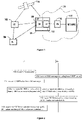
- Fig. 1 depicts examples of simplified system architectures only showing some elements and functional entities, all being logical units, whose implementation may differ from what is shown.
- the connections shown in Fig. 1 are logical connections; the actual physical connections may be different. It is apparent to a person skilled in the art that the system typically comprises also other functions and structures than those shown in Fig. 1 .
- Fig. 1 shows a part of an exemplifying radio access network.
- the radio access network may support sidelink communications described below in more detail.
- Fig. 1 shows devices 100 and 102.
- the devices 100 and 102 are configured to be in a wireless connection on one or more communication channels with a node 104.
- the node 104 is further connected to a core network 106.
- the node 104 may be an access node such as (e/g)NodeB serving devices in a cell.
- the node 104 may be a non-3GPP access node.
- the physical link from a device to a (e/g)NodeB is called uplink or reverse link and the physical link from the (e/g)NodeB to the device is called downlink or forward link.
- (e/g)NodeBs or their functionalities may be implemented by using any node, host, server or access point etc. entity suitable for such a usage.
- a communications system typically comprises more than one (e/g)NodeB in which case the (e/g)NodeBs may also be configured to communicate with one another over links, wired or wireless, designed for the purpose. These links may be used for signalling purposes.
- the (e/g)NodeB is a computing device configured to control the radio resources of communication system it is coupled to.
- the NodeB may also be referred to as a base station, an access point or any other type of interfacing device including a relay station capable of operating in a wireless environment.
- the (e/g)NodeB includes or is coupled to transceivers. From the transceivers of the (e/g)NodeB, a connection is provided to an antenna unit that establishes bi-directional radio links to devices.
- the antenna unit may comprise a plurality of antennas or antenna elements.
- the (e/g)NodeB is further connected to the core network 106 (CN or next generation core NGC). Depending on the deployed technology, the (e/g)NodeB is connected to a serving and packet data network gateway (S-GW +P-GW) or user plane function (UPF), for routing and forwarding user data packets and for providing connectivity of devices to one or more external packet data networks, and to a mobile management entity (MME) or access mobility management function (AMF), for controlling access and mobility of the devices.
- S-GW +P-GW serving and packet data network gateway
- UPF user plane function
- MME mobile management entity
- AMF access mobility management function
- Exemplary embodiments of a device are a subscriber unit, a user device, a user equipment (UE), a user terminal, a terminal device, a mobile station, a mobile device, etc
- the device typically refers to a mobile or static device (e.g. a portable or non-portable computing device) that includes wireless mobile communication devices operating with or without an universal subscriber identification module (USIM), including, but not limited to, the following types of devices: mobile phone, smartphone, personal digital assistant (PDA), handset, device using a wireless modem (alarm or measurement device, etc.), laptop and/or touch screen computer, tablet, game console, notebook, and multimedia device.
- a mobile or static device e.g. a portable or non-portable computing device
- USB universal subscriber identification module
- a device may also be a nearly exclusive uplink only device, of which an example is a camera or video camera loading images or video clips to a network.
- a device may also be a device having capability to operate in Internet of Things (loT) network which is a scenario in which objects are provided with the ability to transfer data over a network without requiring human-to-human or human-to-computer interaction, e.g. to be used in smart power grids and connected vehicles.
- the device may also utilise cloud.
- a device may comprise a user portable device with radio parts (such as a watch, earphones or eyeglasses) and the computation is carried out in the cloud.
- the device illustrates one type of an apparatus to which resources on the air interface are allocated and assigned, and thus any feature described herein with a device may be implemented with a corresponding apparatus, such as a relay node.
- a relay node is a layer 3 relay (self-backhauling relay) towards the base station.
- the device (or in some embodiments a layer 3 relay node) is configured to perform one or more of user equipment functionalities.
- CPS cyber-physical system
- ICT interconnected information and communications technology
- devices sensors, actuators, processors microcontrollers, etc.
- mobile cyber physical systems in which the physical system in question has inherent mobility, are a subcategory of cyber-physical systems. Examples of mobile physical systems include mobile robotics and electronics transported by humans or animals.
- apparatuses have been depicted as single entities, different units, processors and/or memory units (not all shown in Fig. 1 ) may be implemented.
- 5G enables using multiple input - multiple output (MIMO) antennas, many more base stations or nodes than the LTE (a so-called small cell concept), including macro sites operating in co-operation with smaller stations and employing a variety of radio technologies depending on service needs, use cases and/or spectrum available.
- 5G mobile communications supports a wide range of use cases and related applications including video streaming, augmented reality, different ways of data sharing and various forms of machine type applications (such as (massive) machine-type communications (mMTC), including vehicular safety, different sensors and real-time control).
- 5G is expected to have multiple radio interfaces, e.g. below 6GHz or above 24 GHz, cmWave and mmWave, and also being integrable with existing legacy radio access technologies, such as the LTE.
- Integration with the LTE may be implemented, at least in the early phase, as a system, where macro coverage is provided by the LTE and 5G radio interface access comes from small cells by aggregation to the LTE.
- 5G is planned to support both inter-RAT operability (such as LTE-5G) and inter-RI operability (inter-radio interface operability, such as below 6GHz - cmWave, 6 or above 24 GHz - cmWave and mmWave).
- inter-RAT operability such as LTE-5G
- inter-RI operability inter-radio interface operability, such as below 6GHz - cmWave, 6 or above 24 GHz - cmWave and mmWave.
- One of the concepts considered to be used in 5G networks is network slicing in which multiple independent and dedicated virtual sub-networks (network instances) may be created within the same infrastructure to run services that have different requirements on latency, reliability, throughput and mobility.
- the current architecture in LTE networks is fully distributed in the radio and fully centralized in the core network.
- the low latency applications and services in 5G require to bring the content close to the radio which leads to local break out and multi-access edge computing (MEC).
- MEC multi-access edge computing
- 5G enables analytics and knowledge generation to occur at the source of the data. This approach requires leveraging resources that may not be continuously connected to a network such as laptops, smartphones, tablets and sensors.
- MEC provides a distributed computing environment for application and service hosting. It also has the ability to store and process content in close proximity to cellular subscribers for faster response time.
- Edge computing covers a wide range of technologies such as wireless sensor networks, mobile data acquisition, mobile signature analysis, cooperative distributed peer-to-peer ad hoc networking and processing also classifiable as local cloud/fog computing and grid/mesh computing, dew computing, mobile edge computing, cloudlet, distributed data storage and retrieval, autonomic self-healing networks, remote cloud services, augmented and virtual reality, data caching, Internet of Things (massive connectivity and/or latency critical), critical communications (autonomous vehicles, traffic safety, real-time analytics, time-critical control, healthcare applications).
- the communication system is also able to communicate with other networks 112, such as a public switched telephone network, or a VoIP network, or the Internet, or a private network, or utilize services provided by them.
- the communication network may also be able to support the usage of cloud services, for example at least part of core network operations may be carried out as a cloud service (this is depicted in Fig. 1 by "cloud" 114).
- the communication system may also comprise a central control entity, or a like, providing facilities for networks of different operators to cooperate for example in spectrum sharing.
- Edge cloud may be brought into a radio access network (RAN) by utilizing network function virtualization (NFV) and software defined networking (SDN).
- RAN radio access network
- NFV network function virtualization
- SDN software defined networking
- Using the technology of edge cloud may mean access node operations to be carried out, at least partly, in a server, host or node operationally coupled to a remote radio head or base station comprising radio parts. It is also possible that node operations will be distributed among a plurality of servers, nodes or hosts.
- Application of cloudRAN architecture enables RAN real time functions being carried out at or close to a remote antenna site (in a distributed unit, DU 108) and non-real time functions being carried out in a centralized manner (in a centralized unit, CU 110).
- 5G may also utilize satellite communication to enhance or complement the coverage of 5G service, for example by providing backhauling.
- Possible use cases are providing service continuity for machine-to-machine (M2M) or Internet of Things (loT) devices or for passengers on board of vehicles, Mobile Broadband, (MBB) or ensuring service availability for critical communications, and future railway/maritime/aeronautical communications.
- Satellite communication may utilise geostationary earth orbit (GEO) satellite systems, but also low earth orbit (LEO) satellite systems, in particular megaconstellations (systems in which hundreds of (nano)satellites are deployed).
- GEO geostationary earth orbit
- LEO low earth orbit
- megaconstellations systems in which hundreds of (nano)satellites are deployed.
- Each satellite in the mega-constellation may cover several satellite-enabled network entities that create on-ground cells.
- the on-ground cells may be created through an on-ground relay node or by a gNB located on-ground or in a
- the depicted system is only an example of a part of a radio access system and in practice, the system may comprise a plurality of (e/g)NodeBs, the device may have an access to a plurality of radio cells and the system may comprise also other apparatuses, such as physical layer relay nodes or other network elements, etc. At least one of the (e/g)NodeBs or may be a Home(e/g)nodeB. Additionally, in a geographical area of a radio communication system a plurality of different kinds of radio cells as well as a plurality of radio cells may be provided.
- Radio cells may be macro cells (or umbrella cells) which are large cells, usually having a diameter of up to tens of kilometers, or smaller cells such as micro-, femto- or picocells.
- the (e/g)NodeBs of Fig. 1 may provide any kind of these cells.
- a cellular radio system may be implemented as a multilayer network including several kinds of cells. Typically, in multilayer networks, one access node provides one kind of a cell or cells, and thus a plurality of (e/g)NodeBs are required to provide such a network structure.
- a network which is able to use “plug-and-play" (e/g)Node Bs includes, in addition to Home (e/g)NodeBs (H(e/g)nodeBs), a home node B gateway, or HNB-GW (not shown in Fig. 1 ).
- HNB-GW HNB Gateway
- a HNB Gateway (HNB-GW) which is typically installed within an operator's network may aggregate traffic from a large number of HNBs back to a core network.
- FIG 2 illustrates an example of operations at a device implementing user equipment functionality, hereafter referred to as UE (such as e.g. UE 100 of Figure 1 ) and a device implementing base station functionality, hereafter referred to as BS (such as e.g. the e/gNB node 104 of Figure 1 ).
- UE 100 makes a random access preamble transmission (OPERATION 200 of Figure 2 ).
- the random access preamble transmission is successful, and BS 104 transmits a random access reply (RAR) message (OPERATION 202 of Figure 2 ).
- RAR random access reply
- the RAR message includes a base identifier value (hereafter referred to as base C-RNTI (cell-radio network temporary identifier) value) for UE 100 to use as a start value to compute identifier values for the UE 100.
- UE 100 recovers the base C-RNTI value from the RAR message (OPERATION 204 of Figure 2 ).
- both UE 100 and BS 104 separately perform the same pre-determined computation of an identifier value (hereafter referred to as dynamic C-RNTI or DC-RNTI value) for the UE 100, using the base C-RNTI value as one input (OPERATIONS 206a and 206b of Figure 2 ).
- Duplicating BS computation of a DC-RNTI value for UE 100 at UE 100 uses the same one-way mathematical function(s) and inputs as the computation of a DC-RNTI value for UE 100 at BS 104.
- the computation inputs also include; (i) a security key (here referred to as K RNTI ) derived ultimately from a secret key pre-shared between UE 100 and a home subscriber server (HSS), which secret key is primarily used to authenticate the UE subscriber/user; and (ii) a time input related to the time at which both UE 100 and BS 104 are configured to compute the DC-RNTI value for UE 100.
- this time input is the value, at the time of DC-RNTI computation, of the system frame number (SFN) (or alternatively the hyper frame number (HFN)) of the cell via which the UE 100 has the RRC connection.
- SFN system frame number
- HFN hyper frame number
- K RNTI is derived from existing keys K eNB or K gNB , using the key derivation function (KDF) as mentioned in 3GPP TS 33.501, Annex A, with a further input comprising a FC-value from the FC number space controlled by TS 33.220, as mentioned at TS 33.501 A.1.2.
- KDF key derivation function
- the DC-RNTI value is computed from the base C-RNTI value, the SFN/HFN and K RNTI using a one-way mathematical function, such as the ones specified in the Milenage and Tuak algorithm sets identified in TS35.205 and TS35.231.
- the SFN (used in this example as one of the inputs to compute the DC-RNTI value for UE 100) is broadcast by the cell, and has a value shared by all UEs served by the cell.
- An incremented SFN value is broadcast every 10 ms (in the physical broadcast channel (PBCH) for the cell).
- the SFN is 10 bits in length, and may therefore have 1024 different values.
- a hyper frame number (HFN) of the kind implemented in LTE is used instead of SFN as an input for computation of the DC-RNTI value.
- the HFN value increments when the SFN value is equal to 0.
- the HFN is also 10 bits in length.
- the timing reference broadcast in 5G NR as part of the 9th System Information Block (SIB9) is used instead of SFN or HFN as one input for computation of the DC-RNTI value.
- SIB9 System Information Block
- BS 104 incorporates the DC-RNTI value computed at BS 104 for UE 100 into one or more control downlink channel transmissions (e.g. PDCCH transmissions) specific to UE 100 (OPERATION 208 of Figure 2 ); and UE 100 searches a search space for control channel transmissions incorporating a DC-RNTI value matching the DC-RNTI value computed at UE 100 for UE 100 (OPERATION 210 of Figure 2 ).
- control downlink channel transmissions e.g. PDCCH transmissions
- UE 100 searches a search space for control channel transmissions incorporating a DC-RNTI value matching the DC-RNTI value computed at UE 100 for UE 100 (OPERATION 210 of Figure 2 ).
- incorporating the computed DC-RNTI value into a control channel transmission involves using the computed DC-RNTI value to modify the CRC (cyclic redundancy check) attached to the PDCCH payload (DCI (downlink control information) through a scrambling operation; and UE 100 searches the search space for a PDCCH transmission that it can correctly decode using the DC-RNTI value computed at UE 100.
- CRC cyclic redundancy check
- DCI downlink control information
- the computed DC-RNTI value is thus used by UE 100 and BS 104 to distinguish control channel transmissions specific to the UE 100 from control channel transmissions specific to other UEs searching the same search space for DCI messages specific thereto.
- a control channel transmission (e.g. PDCCH transmission) incorporating the computed DC-RNTI value for UE 100 indicates data channel radio resources allocated to uplink transmissions by UE 100 and/or downlink transmissions specific to UE 100.
- UE 100 is representative of a plurality of UEs searching the same search space for PDCCH transmissions incorporating a DC-RNTI value matching a DC-RNTI value computed at the respective UE based on a respective base C-RNTI value and a respective security key (K RNTI ).
- BS 104 periodically computes a fresh DC-RNTI for UE 100, and UE 100 duplicates the periodic computation of fresh DC-RNTI, again using the same one-way mathematical function and input parameters as BS 104.
- UE 100 and BS 104 may compute a fresh DC-RNTI (using e.g. the current SFN value as one input) at predetermined times (e.g. at predetermined values of SFN).
- the period between successive computations of a DC-RNTI value may, for example, be in the range of 10ms to hours or days.
- UE 100 regularly determines whether the current SFN value is one for which the UE 100 is configured to compute a new DC-RNTI value (OPERATION 60). If the determination is negative, UE 100 continues to search the PDCCH search space for PDCCH transmissions incorporating a DC-RNTI value matching the existing DC-RNTI value (i.e. the DC-RNTI value most recently computed at UE 100) (OPERATION 62).
- UE 100 computes a new DC-RNTI value using the current SFN value as one input, and subsequently searches the PDCCH search space for PDCCH transmissions incorporating a DC-RNTI value matching the new DC-RNTI value computed at UE 100 (OPERATION 64 of Figure 6 ).
- one of the input parameters is the SFN value for the cell at the time of DC-RNTI computation, which is different to the SFN value used for the previous DC-RNTI computation and is also different to the SFN value that will be used for the subsequent DC-RNTI computation.
- control channel transmissions specific to UE 100 incorporate changing identifier values over time.
- UE 100 is representative of a plurality of UEs searching the same search space for control channel transmissions incorporating a DC-RNTI value matching the DC-RNTI value computed at UE 100 (based on the respective base C-RNTI value and respective security key value).
- other UEs (or all UEs) of the plurality of UEs searching the same search space for PDCCH transmissions compute respective fresh DC-RNTI values at the same time.
- the SFN/HFN values at which DC-RNTI computation is performed is the same for other UEs (e.g. all UEs searching the search space for control channel transmissions).
- BS 104 triggers the computation of a fresh DC-RNTI value.
- the trigger may take the form of an encrypted RRC message.
- Figure 3 illustrates an example of operations at BS 104 aimed at avoiding DC-RNTI clashes between UEs searching the same search space for PDCCH transmissions.
- the operations are aimed at guaranteeing that the DC-RNTI value for UE 100 is unique to UE 100 at least among all UEs simultaneously searching the same search space for PDCCH transmissions.
- BS 104 precomputes a sequence of DC-RNTI values for UE 100 based respectively on the predetermined SFN values at which UE 100 is configured to perform DC-RNTI computation (OPERATION 300 of Figure 3 ).
- the computation of each DC-RNTI value of the sequence is also based on the base C-RNTI value for UE 100 and the K RNTI value for UE 100.
- the sequence of DC-RNTI values may comprise a predetermined number of DC-RNTI values (for a predetermined number of DC-RNTI computations for UE 100) or DC-RNTI values for a predetermined period of time.
- BS 104 does the same precomputation for all other UEs sharing the same PDCCH search space as UE 104.
- BS 104 determines (OPERATION 302 of Figure 3 ) whether this pre-computation predicts one or more instances of DC-RNTI clashes with any other UE sharing the same PDCCH search space. If this pre-computation predicts no instances of any DC-RNTI clashes (i.e. predicts no instances of more than one UE computing the same DC-RNTI value for the same SFN value input), BS 104 takes no corrective action and uses the pre-computed DC-RNTI values for UE-specific PDCCH transmissions (OPERATION 310 of Figure 3 ).
- BS 104 precomputes a new sequence of DC-RNTI values for UE 100 based on a new base C-RNTI value (OPERATION 304 of Figure 3 ) and determines (OPERATION 306 of Figure 3 ) whether this pre-computation based on a new base C-RNTI value predicts one or more instances of DC-RNTI clashes with any other UE sharing the same PDCCH search space (OPERATION 306).
- BS 104 repeats this pair of operations 304 and 306 until it finds a new base C-RNTI value for which the pre-computation does not predict any DC-RNTI clashes.
- BS 104 then directs UE 100 to use the new base C-RNTI value for the computation of DC-RNTIs (OPERATION 308 of Figure 3 ).
- the new base C-RNTI value for UE 100 can be sent to the UE 100 via radio resources indicated to UE 100 by a PDCCH transmission incorporating the currently valid DC-RNTI value for UE 100.
- Another example technique for avoiding DC-RNTI clashes is as follows. Instead of precomputing a future sequence of DC-RNTI values for UE 100 (and respective future sequences of DC-RNTI values for other UEs sharing the same PDCCH search space with UE 100), BS 104 checks for DC-RNTI clashes each time DC-RNTI values are about to be recomputed at UEs including UE 100.
- BS 104 tries one or more new base C-RNTI values for UE 100 until BS 104 finds a new base C-RNTI value for which pre-computation of DC-RNTI values predicts no DC-RNTI clashes; and BS 104 sends the new base C-RNTI value to UE 100.
- the implementation described so far has the advantage that no new information has to be passed between UE 100 and BS 104 for the generation of DC-RNTI values, except when an individual configuration for changing the DC-RNTI value is required, and/or unless a precomputation of DC-RNTI values at BS 104 predicts a DC-RNTI clash.
- the inputs for computing DC-RNTI values for UE are already available to UE 100.
- the base C-RNTI value is the C-RNTI value already included in the RAR message; the security key K RNTI derived from a key already used at UE for other existing purposes at UE 100; and SFN values are already broadcast by the cell.
- BS 104 sends all parameters for computing the DC-RNTIs to UE 100 in an encrypted RRC message, such as, for example, the RRC reconfiguration message sent by BS 104 following the RRC security command procedure.
- computation at the UE 100 may be based on: a K RNTI value included in the encrypted RRC message; a starting value (instead of the C-RNTI value included in the RAR message); and the SFN value.
- UE 100 does not duplicate the BS computation of DC-RNTI values, but instead receives from BS 104 a sequence of DC-RNTI values to use over a period of time.
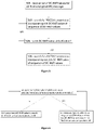
- FIGs 4 and 5 show a representation of the operations at BS 104 and UE 100 according to this example embodiment.
- BS 104 sends to UE 100 a sequence of DC-RNTI values that do not clash with DC-RNTI values sent to other UEs sharing the same PDCCH search space.
- the sequence of DC-RNTI values for UE 100 may be sent to UE 100 in an encrypted RRC message via data channel resources (e.g. PDSCH resources) indicated by a PDCCH transmission incorporating the C-RNTI value included in the RAR message (OPERATION 400 of Figure 4 ).
- UE 100 recovers the sequence of DC-RNTI values from the encrypted RRC message (OPERATION 500 of Figure 5 ).
- the DC-RNTI values of the sequence of DC-RNTI values are valid for respective consecutive periods of time; and UE 100 and BS 104 selectively use the DC-RNTI values of the sequence of DC-RNTI values for the respective periods of time for which they are valid.
- BS 104 incorporates an nth DC-RNTI value into PDCCH transmissions specific to UE 100 for as long as the nth DC-RNTI value is valid, and then switches to incorporating the (n+1)th DC-RNTI value of the set of values into PDCCH transmissions specific to UE 100; and so on.
- UE searches for PDCCH transmissions incorporating an nth DC-RNTI value for as long as the nth DC-RNTI value is valid, and then switches to searching for PDCCH transmissions incorporating the (n+1)th DC-RNTI value of the set of values; and so on.
- either (i) the information necessary for duplicating base station computation of DC-RNTI at UE 100 or (ii) a set of DC-RNTI values for UE 100, may be included in a RRC reconfiguration message sent to command or trigger a handover of UE 100 from a source cell to a target cell.
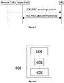
- Figure 7 shows a representation of an example of a handover of UE 100 from a source cell to a target cell.
- UE 100 receives (OPERATION 700 of Figure 7 ) via the source cell a RRC reconfiguration message including either (i) all the information UE 100 needs to duplicate base station computation of DC-RNTI value(s) at UE 100 or (ii) a sequence of DC-RNTI values.
- UE 100 performs handover (OPERATION 702 of Figure 7 ) using a DC-RNTI value computed at UE 100 using the information included in the RRC reconfiguration message, or a first one of the provided sequence of DC-RNTI values included in the RRC reconfiguration message.
- Sending such an encrypted RRC reconfiguration message also in the event of an intracell handover (for which the source cell and the target cell are the same and only the used channel is changed) provides an opportunity to securely re-set the computation of DC-RNTI at UE 100 or provide UE 100 with a new sequence of DC-RNTI values.
- UE may use a DC-RNTI value computed at UE 100 (or one of a sequence of DC-RNTI values received previously in an encrypted message via the serving cell). For the example of computing a DC-RNTI value at UE 100, the UE 100 reads the current SFN value from the master information block (MIB) broadcast by the serving cell.
- MIB master information block
- the example embodiments described above can reduce the risk of a malicious third party being able to track the PDCCH transmissions specific to UE 100, and thus can increase security against PDCCH-tracking based attacks, and against man-in-the-middle (MITM) attacks by fake base stations (FBSs).
- MITM man-in-the-middle
- the example embodiments can reduce the effectiveness of attacks in which the attacker relies on being able to identify PDCCH transmissions related to a GUTI (Globally Unique Temporary Identifier) or SUCI (Subscription Concealed Identifier) included in a register request via data channel resources scheduled by a PDCCH transmission.
- GUTI Globally Unique Temporary Identifier
- SUCI Subscribescription Concealed Identifier
- the example embodiments can thus reduce the risk of a malicious third party (with the extra assistance of additional intelligence (like physical observation)) being able to identify the human subscriber using the UE that sent the register request including the GUTI or SUCI.
- the example embodiments can reduce the effectiveness of attacks involving a malicious attacker sending traffic (e.g. a series of silent short messages, or a series of messenger messages) to a public address of a human victim known by the attacker to have a UE served by a particular cell, and then exploiting the characteristics of the traffic resulting from the traffic originated by the malicious attacker (like number and length of messages, timing).
- traffic e.g. a series of silent short messages, or a series of messenger messages
- the example embodiments can increase security in networks where the GUTI is not changed frequently, by increasing the difficulty of determining which PDCCH transmissions are related to a GUTI (i.e. specific to a UE having the GUTI).
- the example embodiments can reduce the effectiveness of malicious attacks involving the attacker finding (by monitoring both source and target cells for a handover of UE 100 (and having possibly also other intelligence)) the C-RNTI value used in a random access (RA) procedure for the UE.
- RA random access
- the example embodiments can increase security against IMP4GT (IMPersonation Attacks in 4G NeTworks) involving an attacker relying on being able to map PDCCH transmissions to a GUTI.
- IMP4GT IMPersonation Attacks in 4G NeTworks
- IMP4GT is described in a paper entitled " IMP4GT: IMPersonation Attacks in 4G NeTworks by David Rupprecht et al (DOI:10.14722/ndss.2020.24283 ).
- the example embodiments can reduce the effectiveness of attacks involving exploitation of unencrypted MAC control elements sent to a certain UE.
- Figure 8 illustrates an example of an apparatus for implementing the operations of a device implementing UE or BS functionality.
- the apparatus may comprise at least one processor 602 coupled to one or more interfaces 608.
- the one or more interfaces may be e.g. to other equipment for which the UE functionality provides radio communications.
- the one or more interfaces may be e.g. to other devices implementing other network functionality such as devices implementing UPF (User Plane Function) functionality in a 5G system.
- the at least one processor 602 is also coupled to a radio unit 604 including one or more antennas etc. for making and receiving radio transmissions.
- the at least one processor 602 may also be coupled to at least one memory 606.
- the at least one processor 602 may be configured to execute an appropriate software code to perform the operations described above.
- the software code may be stored in the memory 606
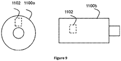
- Figure 9 shows a schematic representation of non-volatile memory media 1100a (e.g. computer disc (CD) or digital versatile disc (DVD)) and 1100b (e.g. universal serial bus (USB) memory stick) storing instructions and/or parameters 1102 which when executed by a processor allow the processor to perform one or more of the steps of the methods described previously.
- non-volatile memory media 1100a e.g. computer disc (CD) or digital versatile disc (DVD)
- 1100b e.g. universal serial bus (USB) memory stick
- embodiments of the present invention may be implemented as circuitry, in software, hardware, application logic or a combination of software, hardware and application logic.
- the application logic, software or an instruction set is maintained on any one of various conventional computer-readable media.
- a "computer-readable medium” may be any media or means that can contain, store, communicate, propagate or transport the instructions for use by or in connection with an instruction execution system, apparatus, or device, such as the base stations or user equipment of the above-described embodiments.
- circuitry refers to all of the following: (a) hardwareonly circuit implementations (such as implementations in only analog and/or digital circuitry) and (b) to combinations of circuits and software (and/or firmware), such as (as applicable): (i) to a combination of processor(s) or (ii) to portions of processor(s)/software (including digital signal processor(s)), software, and memory(ies) that work together to cause an apparatus, such as the user equipment or base stations of the above-described embodiments, to perform various functions) and (c) to circuits, such as a microprocessor(s) or a portion of a microprocessor(s), that require software or firmware for operation, even if the software or firmware is not physically present.
- circuitry would also cover an implementation of merely a processor (or multiple processors) or portion of a processor and its (or their) accompanying software and/or firmware.
- circuitry would also cover, for example and if applicable to the particular claim element, a baseband integrated circuit or applications processor integrated circuit for a mobile phone or a similar integrated circuit in server, a cellular network device, or other network device.
Landscapes
- Engineering & Computer Science (AREA)
- Signal Processing (AREA)
- Computer Networks & Wireless Communication (AREA)
- Computer Security & Cryptography (AREA)
- Mobile Radio Communication Systems (AREA)
Abstract
Description
- The present disclosure relates to apparatus, a method, and a computer program, and in particular but not exclusively to apparatus, methods and computer programs for communication systems involving the incorporation into control channel transmissions of identifiers by which a user equipment (UE) can identify control channel transmissions specific thereto.
- Some communication systems involve a base station (e.g. eNB or gNB) making UE-specific control channel transmissions (e.g. physical downlink control channel PDCCH transmission) for a plurality of UEs. A control channel transmission specific to a UE may, for example, indicate the allocation of data channel resources (e.g. physical downlink shared channel PDSCH and/or physical uplink shared channel PUSCH resources) to uplink and/or downlink transmissions for the UE. A control channel transmission specific to a UE incorporates an identifier for the UE. The UE searches control channel transmission resources for a control channel transmission incorporating the identifier for the UE.
- A method comprising: duplicating, at a user equipment, base station computation of an identifier value for the user equipment; and searching, at the user equipment, for one or more control channel transmissions incorporating an identifier value matching the identifier value computed at the user equipment.
- Duplicating base station computation of an identifier value for the user equipment may comprise computing an identifier value based on one or more input parameter values and one or more mathematical functions used at the base station to compute an identifier value for the user equipment.
- Computation of an identifier value may be based at least partly on a value of a time-related parameter; and the computed identifier value may be effective for a time period related to the value of the time-related parameter.
- The method may further comprise: duplicating, at the user equipment, base station computation of a further identifier value; and after expiry of the time period, searching at the user equipment for one or more control channel transmissions incorporating an identifier value matching the further identifier value computed at the user equipment.
- The time-related parameter may be a system frame number.
- Computation of an identifier value may be at least partly based on a security key value derived at least partly from a secret key shared between the base station and the user equipment.
- Computation of an identifier value may be at least partly based on a start value included in a random access reply message.
- The one or more control channel transmissions may indicate radio resources allocated to the user equipment for downlink and/or uplink transmissions.
- A method comprising: duplicating, at a base station, user equipment computation of an identifier value for the user equipment; and incorporating the identifier value into one or more control channel transmissions specific to the user equipment.
- Duplicating user equipment computation of an identifier value for the user equipment may comprise computing an identifier value based on one or more input parameter values and one or more mathematical functions used at the user equipment to compute an identifier value for the user equipment.
- The method may further comprise: sending to the user equipment a base value for computation of an identifier value; and in response to thereafter determining that computation based on the base value generates an identifier value that clashes with one or more identifier values for one or more other user equipments sharing radio resources for control channel transmissions with the user equipment, sending a new base value to the user equipment.
- A method comprising: recovering, at a user equipment, a sequence of identifier values for the user equipment from a radio transmission; and searching at the user equipment for one or more control channel transmissions incorporating an identifier value matching one of the sequence of identifier values.
- The sequence of identifier values for the user equipment may comprise at least a first identifier value effective for a first time period, and a second identifier value effective for a second time period after the first time period; and the method may comprise: during the first time period searching at the user equipment for one or more control channel transmissions incorporating an identifier value matching the first identifier value; and during the second time period searching at the user equipment for one or more control channel transmissions incorporating an identifier value matching the second identifier value.
- A method comprising: transmitting, from a base station, an indication of a sequence of identifier values for a user equipment; and incorporating one of the sequence of identifier values for the user equipment into one or more control channel transmissions specific to the user equipment.
- The sequence of identifier values for the user equipment may comprise at least a first identifier value effective for a first time period, and a second identifier value effective for a second time period after the first time period; and the method may comprise: during the first time period making one or more control channel transmissions incorporating the first identifier value; and during the second time period making one or more control channel transmissions incorporating the second identifier value.
- Apparatus comprising: means for duplicating base station computation of an identifier value for a user equipment; and means for searching for one or more control channel transmissions incorporating an identifier value matching the identifier value.
- The means for duplicating base station computation of an identifier value for the user equipment may comprise means for computing an identifier value based on one or more input parameter values and one or more mathematical functions used at the base station to compute an identifier value for the user equipment.
- Computation of an identifier value may be based at least partly on a value of a time-related parameter; and the computed identifier value may be effective for a time period related to the value of the time-related parameter.
- The apparatus may further comprise: means for duplicating base station computation of a further identifier value; and means for, after expiry of the time period, searching for one or more control channel transmissions incorporating an identifier value matching the further identifier value.
- The time-related parameter may be a system frame number.
- Computation of an identifier value may be at least partly based on a security key value derived at least partly from a secret key shared between the base station and the user equipment.
- Computation of an identifier value may be at least partly based on a start value included in a random access reply message.
- The one or more control channel transmissions may indicate radio resources allocated to the user equipment for downlink and/or uplink transmissions.
- Apparatus comprising: means for duplicating user equipment computation of an identifier value for the user equipment; and means for incorporating the identifier value into one or more control channel transmissions specific to the user equipment.
- The means for duplicating user equipment computation of an identifier value for the user equipment may comprise means for computing an identifier value based on one or more input parameter values and one or more mathematical functions used at the user equipment to compute an identifier value for the user equipment.
- The apparatus may comprise: means for sending to the user equipment a base value for computation of an identifier value; and means for, in response to thereafter determining that computation based on the base value generates an identifier value that clashes with one or more identifier values for one or more other user equipments sharing radio resources for control channel transmissions with the user equipment, sending a new base value to the user equipment.
- Apparatus comprising: means for recovering a sequence of identifier values for a user equipment from a radio transmission; and means for searching for one or more control channel transmissions incorporating an identifier value matching one of the sequence of identifier values.
- The sequence of identifier values for the user equipment may comprise at least a first identifier value effective for a first time period, and a second identifier value effective for a second time period after the first time period; and the apparatus may comprise: means for, during the first time period, searching for one or more control channel transmissions incorporating an identifier value matching the first identifier value, and, during the second time period, searching for one or more control channel transmissions incorporating an identifier value matching the second identifier value.
- Apparatus comprising: means for transmitting an indication of a sequence of identifier values for a user equipment; and means for incorporating one of the sequence of identifier values for the user equipment into one or more control channel transmissions specific to the user equipment.
- The sequence of identifier values for the user equipment may comprise at least a first identifier value effective for a first time period, and a second identifier value effective for a second time period after the first time period; and the apparatus may comprise: means for, during the first time period, making one or more control channel transmissions incorporating the first identifier value, and, during the second time period, making one or more control channel transmissions incorporating the second identifier value.
- An apparatus comprising: at least one processor; and at least one memory including computer program code, the at least one memory and computer program code configured to, with the at least one processor, cause the apparatus to perform:
- duplicating base station computation of an identifier value for a user equipment; and searching for one or more control channel transmissions incorporating an identifier value matching the identifier value.
- Duplicating base station computation of an identifier value for the user equipment may comprise computing an identifier value based on one or more input parameter values and one or more mathematical functions used at the base station to compute an identifier value for the user equipment.
- Computation of an identifier value may be based at least partly on a value of a time-related parameter; and the computed identifier value may be effective for a time period related to the value of the time-related parameter.
- The at least one memory and computer program code may be configured to, with the at least one processor, cause the apparatus to: duplicate base station computation of a further identifier value; and after expiry of the time period, search for one or more control channel transmissions incorporating an identifier value matching the further identifier value.
- The time-related parameter may be a system frame number.
- Computation of an identifier value may be at least partly based on a security key value derived at least partly from a secret key shared between the base station and the user equipment.
- Computation of an identifier value may be at least partly based on a start value included in a random access reply message.
- The one or more control channel transmissions may indicate radio resources allocated to the user equipment for downlink and/or uplink transmissions.
- An apparatus comprising: at least one processor; and at least one memory including computer program code, the at least one memory and computer program code configured to, with the at least one processor, cause the apparatus to perform: duplicating user equipment computation of an identifier value for a user equipment; and incorporating the identifier value into one or more control channel transmissions specific to the user equipment.
- Duplicating user equipment computation of an identifier value for the user equipment may comprise computing an identifier value based on one or more input parameter values and one or more mathematical functions used at the user equipment to compute an identifier value for the user equipment.
- The at least one memory and computer program code may be configured to, with the at least one processor, cause the apparatus to: send to the user equipment a base value for computation of an identifier value; and in response to thereafter determining that computation based on the base value generates an identifier value that clashes with one or more identifier values for one or more other user equipments sharing radio resources for control channel transmissions with the user equipment, send a new base value to the user equipment.
- An apparatus comprising: at least one processor; and at least one memory including computer program code, the at least one memory and computer program code configured to, with the at least one processor, cause the apparatus to perform: recovering a sequence of identifier values for a user equipment from a radio transmission; and searching for one or more control channel transmissions incorporating an identifier value matching one of the sequence of identifier values.
- The sequence of identifier values for the user equipment may comprise at least a first identifier value effective for a first time period, and a second identifier value effective for a second time period after the first time period; and the at least one memory and computer program code may be configured to, with the at least one processor, cause the apparatus to: during the first time period, search for one or more control channel transmissions incorporating an identifier value matching the first identifier value; and during the second time period, search at the user equipment for one or more control channel transmissions incorporating an identifier value matching the second identifier value.
- An apparatus comprising: at least one processor; and at least one memory including computer program code, the at least one memory and computer program code configured to, with the at least one processor, cause the apparatus to perform: transmitting an indication of a sequence of identifier values for a user equipment; and incorporating one of the sequence of identifier values for the user equipment into one or more control channel transmissions specific to the user equipment.
- The sequence of identifier values for the user equipment may comprise at least a first identifier value effective for a first time period, and a second identifier value effective for a second time period after the first time period; and the at least one memory and computer program code may be configured to, with the at least one processor, cause the apparatus to: during the first time period, make one or more control channel transmissions incorporating the first identifier value; and during the second time period. make one or more control channel transmissions incorporating the second identifier value.
- Apparatus comprising: duplicating circuitry for duplicating base station computation of an identifier value for a user equipment; and searching circuitry for searching for one or more control channel transmissions incorporating an identifier value matching the identifier value.
- Apparatus comprising: duplicating circuitry for duplicating user equipment computation of an identifier value for the user equipment; and incorporating circuitry for incorporating the identifier value into one or more control channel transmissions specific to the user equipment.
- Apparatus comprising: recovering circuitry for recovering a sequence of identifier values for a user equipment from a radio transmission; and searching circuitry for searching for one or more control channel transmissions incorporating an identifier value matching one of the sequence of identifier values.
- Apparatus comprising: transmitting circuitry for transmitting an indication of a sequence of identifier values for a user equipment; and incorporating circuitry for incorporating one of the sequence of identifier values for the user equipment into one or more control channel transmissions specific to the user equipment.
- A computer readable medium comprising program instructions stored thereon for performing: duplicating, at a user equipment, base station computation of an identifier value for the user equipment; and searching, at the user equipment, for one or more control channel transmissions incorporating an identifier value matching the identifier value computed at the user equipment.
- A computer readable medium comprising program instructions stored thereon for performing: duplicating, at a base station, user equipment computation of an identifier value for the user equipment; and incorporating the identifier value into one or more control channel transmissions specific to the user equipment.
- A computer readable medium comprising program instructions stored thereon for performing: recovering, at a user equipment, a sequence of identifier values for the user equipment from a radio transmission; and searching at the user equipment for one or more control channel transmissions incorporating an identifier value matching one of the sequence of identifier values.
- A computer readable medium comprising program instructions stored thereon for performing: transmitting, from a base station, an indication of a sequence of identifier values for a user equipment; and incorporating one of the sequence of identifier values for the user equipment into one or more control channel transmissions specific to the user equipment.
- A computer program comprising computer executable code which when run on at least one processor is configured to cause an apparatus at least to: duplicate base station computation of an identifier value for a user equipment; and search for one or more control channel transmissions incorporating an identifier value matching the identifier value.
- A computer program comprising computer executable code which when run on at least one processor is configured to cause an apparatus at least to: duplicate user equipment computation of an identifier value for a user equipment; and incorporate the identifier value into one or more control channel transmissions specific to the user equipment.
- A computer program comprising computer executable code which when run on at least one processor is configured to cause an apparatus at least to: recover a sequence of identifier values for a user equipment from a radio transmission; and search for one or more control channel transmissions incorporating an identifier value matching one of the sequence of identifier values.
- A computer program comprising computer executable code which when run on at least one processor is configured to cause an apparatus at least to: transmit an indication of a sequence of identifier values for a user equipment; and incorporate one of the sequence of identifier values for the user equipment into one or more control channel transmissions specific to the user equipment.
- A non-transitory computer readable medium comprising program instructions stored thereon for performing: duplicating, at a user equipment, base station computation of an identifier value for the user equipment; and searching, at the user equipment, for one or more control channel transmissions incorporating an identifier value matching the identifier value computed at the user equipment.
- A non-transitory computer readable medium comprising program instructions stored thereon for performing: duplicating, at a base station, user equipment computation of an identifier value for the user equipment; and incorporating the identifier value into one or more control channel transmissions specific to the user equipment.
- A non-transitory computer readable medium comprising program instructions stored thereon for performing: recovering, at a user equipment, a sequence of identifier values for the user equipment from a radio transmission; and searching at the user equipment for one or more control channel transmissions incorporating an identifier value matching one of the sequence of identifier values.
- A non-transitory computer readable medium comprising program instructions stored thereon for performing: transmitting, from a base station, an indication of a sequence of identifier values for a user equipment; and incorporating one of the sequence of identifier values for the user equipment into one or more control channel transmissions specific to the user equipment.
- In the above, many different aspects have been described. It should be appreciated that further aspects may be provided by the combination of any two or more of the aspects described above.
- Various other aspects are also described in the following detailed description and in the attached claims.
- Some example embodiments will now be described in further detail, by way of example only, with reference to the following examples and accompanying drawings, in which:
-
Figure 1 illustrates an example system to which embodiments may be applied; -
Figure 2 shows a representation of an example of operations at a device implementing user equipment functionality and at a device implementing base station functionality according to an example embodiment; -
Figure 3 shows a representation of an example of operations at a device implementing base station functionality according to an example embodiment; -
Figure 4 shows a representation of another example of operations at a device implementing base station functionality according to an example embodiment; -
Figure 5 shows a representation of example of operations at a device implementing user equipment functionality according to an example embodiment; -
Figure 6 shows a representation of an example of operations at a device periodically computing identifier values according to an example embodiment; -
Figure 7 shows a representation of an example of operations for a handover procedure; -
Figure 8 shows a representation of an example of apparatus for implementing operations according to some example embodiments; -
Figure 9 shows a representation of an example of non-volatile memory media. - In the following, different exemplifying embodiments will be described using, as an example of an access architecture to which the embodiments may be applied, a radio access architecture based on long term evolution advanced (LTE Advanced, LTE-A) or new radio (NR, 5G), without restricting the embodiments to such an architecture, however. The embodiments may also be applied to other kinds of communications networks having suitable means by adjusting parameters and procedures appropriately. Some examples of other options for suitable systems are the universal mobile telecommunications system (UMTS) radio access network (UTRAN), wireless local area network (WLAN or WiFi), worldwide interoperability for microwave access (WiMAX), Bluetooth®, personal communications services (PCS), ZigBee®, wideband code division multiple access (WCDMA), systems using ultra-wideband (UWB) technology, sensor networks, mobile ad-hoc networks (MANETs) and Internet Protocol multimedia subsystems (IMS) or any combination thereof.
-
Fig. 1 depicts examples of simplified system architectures only showing some elements and functional entities, all being logical units, whose implementation may differ from what is shown. The connections shown inFig. 1 are logical connections; the actual physical connections may be different. It is apparent to a person skilled in the art that the system typically comprises also other functions and structures than those shown inFig. 1 . - The embodiments are not, however, restricted to the system given as an example but a person skilled in the art may apply the solution to other communication systems provided with necessary properties.
- The example of
Fig. 1 shows a part of an exemplifying radio access network. For example, the radio access network may support sidelink communications described below in more detail. -
Fig. 1 showsdevices devices node 104. Thenode 104 is further connected to acore network 106. In one example, thenode 104 may be an access node such as (e/g)NodeB serving devices in a cell. In one example, thenode 104 may be a non-3GPP access node. The physical link from a device to a (e/g)NodeB is called uplink or reverse link and the physical link from the (e/g)NodeB to the device is called downlink or forward link. It should be appreciated that (e/g)NodeBs or their functionalities may be implemented by using any node, host, server or access point etc. entity suitable for such a usage. - A communications system typically comprises more than one (e/g)NodeB in which case the (e/g)NodeBs may also be configured to communicate with one another over links, wired or wireless, designed for the purpose. These links may be used for signalling purposes. The (e/g)NodeB is a computing device configured to control the radio resources of communication system it is coupled to. The NodeB may also be referred to as a base station, an access point or any other type of interfacing device including a relay station capable of operating in a wireless environment. The (e/g)NodeB includes or is coupled to transceivers. From the transceivers of the (e/g)NodeB, a connection is provided to an antenna unit that establishes bi-directional radio links to devices. The antenna unit may comprise a plurality of antennas or antenna elements. The (e/g)NodeB is further connected to the core network 106 (CN or next generation core NGC). Depending on the deployed technology, the (e/g)NodeB is connected to a serving and packet data network gateway (S-GW +P-GW) or user plane function (UPF), for routing and forwarding user data packets and for providing connectivity of devices to one or more external packet data networks, and to a mobile management entity (MME) or access mobility management function (AMF), for controlling access and mobility of the devices.
- Exemplary embodiments of a device are a subscriber unit, a user device, a user equipment (UE), a user terminal, a terminal device, a mobile station, a mobile device, etc The device typically refers to a mobile or static device ( e.g. a portable or non-portable computing device) that includes wireless mobile communication devices operating with or without an universal subscriber identification module (USIM), including, but not limited to, the following types of devices: mobile phone, smartphone, personal digital assistant (PDA), handset, device using a wireless modem (alarm or measurement device, etc.), laptop and/or touch screen computer, tablet, game console, notebook, and multimedia device. It should be appreciated that a device may also be a nearly exclusive uplink only device, of which an example is a camera or video camera loading images or video clips to a network. A device may also be a device having capability to operate in Internet of Things (loT) network which is a scenario in which objects are provided with the ability to transfer data over a network without requiring human-to-human or human-to-computer interaction, e.g. to be used in smart power grids and connected vehicles. The device may also utilise cloud. In some applications, a device may comprise a user portable device with radio parts (such as a watch, earphones or eyeglasses) and the computation is carried out in the cloud.
- The device illustrates one type of an apparatus to which resources on the air interface are allocated and assigned, and thus any feature described herein with a device may be implemented with a corresponding apparatus, such as a relay node. An example of such a relay node is a layer 3 relay (self-backhauling relay) towards the base station. The device (or in some embodiments a layer 3 relay node) is configured to perform one or more of user equipment functionalities.
- Various techniques described herein may also be applied to a cyber-physical system (CPS) (a system of collaborating computational elements controlling physical entities). CPS may enable the implementation and exploitation of massive amounts of interconnected information and communications technology, ICT, devices (sensors, actuators, processors microcontrollers, etc.) embedded in physical objects at different locations. Mobile cyber physical systems, in which the physical system in question has inherent mobility, are a subcategory of cyber-physical systems. Examples of mobile physical systems include mobile robotics and electronics transported by humans or animals.
- Additionally, although the apparatuses have been depicted as single entities, different units, processors and/or memory units (not all shown in
Fig. 1 ) may be implemented. - 5G enables using multiple input - multiple output (MIMO) antennas, many more base stations or nodes than the LTE (a so-called small cell concept), including macro sites operating in co-operation with smaller stations and employing a variety of radio technologies depending on service needs, use cases and/or spectrum available. 5G mobile communications supports a wide range of use cases and related applications including video streaming, augmented reality, different ways of data sharing and various forms of machine type applications (such as (massive) machine-type communications (mMTC), including vehicular safety, different sensors and real-time control). 5G is expected to have multiple radio interfaces, e.g. below 6GHz or above 24 GHz, cmWave and mmWave, and also being integrable with existing legacy radio access technologies, such as the LTE. Integration with the LTE may be implemented, at least in the early phase, as a system, where macro coverage is provided by the LTE and 5G radio interface access comes from small cells by aggregation to the LTE. In other words, 5G is planned to support both inter-RAT operability (such as LTE-5G) and inter-RI operability (inter-radio interface operability, such as below 6GHz - cmWave, 6 or above 24 GHz - cmWave and mmWave). One of the concepts considered to be used in 5G networks is network slicing in which multiple independent and dedicated virtual sub-networks (network instances) may be created within the same infrastructure to run services that have different requirements on latency, reliability, throughput and mobility.
- The current architecture in LTE networks is fully distributed in the radio and fully centralized in the core network. The low latency applications and services in 5G require to bring the content close to the radio which leads to local break out and multi-access edge computing (MEC). 5G enables analytics and knowledge generation to occur at the source of the data. This approach requires leveraging resources that may not be continuously connected to a network such as laptops, smartphones, tablets and sensors. MEC provides a distributed computing environment for application and service hosting. It also has the ability to store and process content in close proximity to cellular subscribers for faster response time. Edge computing covers a wide range of technologies such as wireless sensor networks, mobile data acquisition, mobile signature analysis, cooperative distributed peer-to-peer ad hoc networking and processing also classifiable as local cloud/fog computing and grid/mesh computing, dew computing, mobile edge computing, cloudlet, distributed data storage and retrieval, autonomic self-healing networks, remote cloud services, augmented and virtual reality, data caching, Internet of Things (massive connectivity and/or latency critical), critical communications (autonomous vehicles, traffic safety, real-time analytics, time-critical control, healthcare applications).
- The communication system is also able to communicate with
other networks 112, such as a public switched telephone network, or a VoIP network, or the Internet, or a private network, or utilize services provided by them. The communication network may also be able to support the usage of cloud services, for example at least part of core network operations may be carried out as a cloud service (this is depicted inFig. 1 by "cloud" 114). The communication system may also comprise a central control entity, or a like, providing facilities for networks of different operators to cooperate for example in spectrum sharing. - The technology of Edge cloud may be brought into a radio access network (RAN) by utilizing network function virtualization (NFV) and software defined networking (SDN). Using the technology of edge cloud may mean access node operations to be carried out, at least partly, in a server, host or node operationally coupled to a remote radio head or base station comprising radio parts. It is also possible that node operations will be distributed among a plurality of servers, nodes or hosts. Application of cloudRAN architecture enables RAN real time functions being carried out at or close to a remote antenna site (in a distributed unit, DU 108) and non-real time functions being carried out in a centralized manner (in a centralized unit, CU 110).
- It should also be understood that the distribution of labour between core network operations and base station operations may differ from that of the LTE or even be nonexistent. Some other technology advancements probably to be used are Big Data and all-IP, which may change the way networks are being constructed and managed. 5G (or new radio, NR) networks are being designed to support multiple hierarchies, where MEC servers can be placed between the core and the base station or nodeB (gNB). It should be appreciated that MEC can be applied in 4G networks as well.
- 5G may also utilize satellite communication to enhance or complement the coverage of 5G service, for example by providing backhauling. Possible use cases are providing service continuity for machine-to-machine (M2M) or Internet of Things (loT) devices or for passengers on board of vehicles, Mobile Broadband, (MBB) or ensuring service availability for critical communications, and future railway/maritime/aeronautical communications. Satellite communication may utilise geostationary earth orbit (GEO) satellite systems, but also low earth orbit (LEO) satellite systems, in particular megaconstellations (systems in which hundreds of (nano)satellites are deployed). Each satellite in the mega-constellation may cover several satellite-enabled network entities that create on-ground cells. The on-ground cells may be created through an on-ground relay node or by a gNB located on-ground or in a satellite.
- It is clear to a person skilled in the art that the depicted system is only an example of a part of a radio access system and in practice, the system may comprise a plurality of (e/g)NodeBs, the device may have an access to a plurality of radio cells and the system may comprise also other apparatuses, such as physical layer relay nodes or other network elements, etc. At least one of the (e/g)NodeBs or may be a Home(e/g)nodeB. Additionally, in a geographical area of a radio communication system a plurality of different kinds of radio cells as well as a plurality of radio cells may be provided. Radio cells may be macro cells (or umbrella cells) which are large cells, usually having a diameter of up to tens of kilometers, or smaller cells such as micro-, femto- or picocells. The (e/g)NodeBs of
Fig. 1 may provide any kind of these cells. A cellular radio system may be implemented as a multilayer network including several kinds of cells. Typically, in multilayer networks, one access node provides one kind of a cell or cells, and thus a plurality of (e/g)NodeBs are required to provide such a network structure. - For fulfilling the need for improving the deployment and performance of communication systems, the concept of "plug-and-play" (e/g)NodeBs has been introduced. Typically, a network which is able to use "plug-and-play" (e/g)Node Bs, includes, in addition to Home (e/g)NodeBs (H(e/g)nodeBs), a home node B gateway, or HNB-GW (not shown in
Fig. 1 ). A HNB Gateway (HNB-GW), which is typically installed within an operator's network may aggregate traffic from a large number of HNBs back to a core network. -
Figure 2 illustrates an example of operations at a device implementing user equipment functionality, hereafter referred to as UE (such ase.g. UE 100 ofFigure 1 ) and a device implementing base station functionality, hereafter referred to as BS (such as e.g. the e/gNB node 104 ofFigure 1 ).UE 100 makes a random access preamble transmission (OPERATION 200 ofFigure 2 ). The random access preamble transmission is successful, andBS 104 transmits a random access reply (RAR) message (OPERATION 202 ofFigure 2 ). The RAR message includes a base identifier value (hereafter referred to as base C-RNTI (cell-radio network temporary identifier) value) forUE 100 to use as a start value to compute identifier values for theUE 100.UE 100 recovers the base C-RNTI value from the RAR message (OPERATION 204 ofFigure 2 ). - Later, both
UE 100 andBS 104 separately perform the same pre-determined computation of an identifier value (hereafter referred to as dynamic C-RNTI or DC-RNTI value) for theUE 100, using the base C-RNTI value as one input (OPERATIONS Figure 2 ). Duplicating BS computation of a DC-RNTI value forUE 100 atUE 100 uses the same one-way mathematical function(s) and inputs as the computation of a DC-RNTI value forUE 100 atBS 104. In this example, the computation inputs also include; (i) a security key (here referred to as KRNTI) derived ultimately from a secret key pre-shared betweenUE 100 and a home subscriber server (HSS), which secret key is primarily used to authenticate the UE subscriber/user; and (ii) a time input related to the time at which bothUE 100 andBS 104 are configured to compute the DC-RNTI value forUE 100. In one example, this time input is the value, at the time of DC-RNTI computation, of the system frame number (SFN) (or alternatively the hyper frame number (HFN)) of the cell via which theUE 100 has the RRC connection. - In this example, KRNTI is derived from existing keys KeNB or KgNB, using the key derivation function (KDF) as mentioned in 3GPP TS 33.501, Annex A, with a further input comprising a FC-value from the FC number space controlled by TS 33.220, as mentioned at TS 33.501 A.1.2.
- In this example, the DC-RNTI value is computed from the base C-RNTI value, the SFN/HFN and KRNTI using a one-way mathematical function, such as the ones specified in the Milenage and Tuak algorithm sets identified in TS35.205 and TS35.231.
- The SFN (used in this example as one of the inputs to compute the DC-RNTI value for UE 100) is broadcast by the cell, and has a value shared by all UEs served by the cell. An incremented SFN value is broadcast every 10 ms (in the physical broadcast channel (PBCH) for the cell). The SFN is 10 bits in length, and may therefore have 1024 different values. The SFN cycle (the time period over which the SFN value repeats) is 1024∗10ms=10.24 seconds.
- In another example, a hyper frame number (HFN) of the kind implemented in LTE is used instead of SFN as an input for computation of the DC-RNTI value. The HFN value increments when the SFN value is equal to 0. The HFN is also 10 bits in length. The HFN cycle (the time period over which the HFN value repeats) is 1024∗1024∗10ms=10485.76 second (about 7 days).
- In another example, the timing reference broadcast in 5G NR as part of the 9th System Information Block (SIB9) is used instead of SFN or HFN as one input for computation of the DC-RNTI value.
-
BS 104 incorporates the DC-RNTI value computed atBS 104 forUE 100 into one or more control downlink channel transmissions (e.g. PDCCH transmissions) specific to UE 100 (OPERATION 208 ofFigure 2 ); andUE 100 searches a search space for control channel transmissions incorporating a DC-RNTI value matching the DC-RNTI value computed atUE 100 for UE 100 (OPERATION 210 ofFigure 2 ). In this example, incorporating the computed DC-RNTI value into a control channel transmission involves using the computed DC-RNTI value to modify the CRC (cyclic redundancy check) attached to the PDCCH payload (DCI (downlink control information) through a scrambling operation; andUE 100 searches the search space for a PDCCH transmission that it can correctly decode using the DC-RNTI value computed atUE 100. - The computed DC-RNTI value is thus used by
UE 100 andBS 104 to distinguish control channel transmissions specific to theUE 100 from control channel transmissions specific to other UEs searching the same search space for DCI messages specific thereto. A control channel transmission (e.g. PDCCH transmission) incorporating the computed DC-RNTI value forUE 100 indicates data channel radio resources allocated to uplink transmissions byUE 100 and/or downlink transmissions specific toUE 100. -
UE 100 is representative of a plurality of UEs searching the same search space for PDCCH transmissions incorporating a DC-RNTI value matching a DC-RNTI value computed at the respective UE based on a respective base C-RNTI value and a respective security key (KRNTI). - According to one example whose representation is shown in
Figure 6 ,BS 104 periodically computes a fresh DC-RNTI forUE 100, andUE 100 duplicates the periodic computation of fresh DC-RNTI, again using the same one-way mathematical function and input parameters asBS 104.UE 100 andBS 104 may compute a fresh DC-RNTI (using e.g. the current SFN value as one input) at predetermined times (e.g. at predetermined values of SFN). The period between successive computations of a DC-RNTI value may, for example, be in the range of 10ms to hours or days. There may be a pre-configured default timing for the fresh computing of-RNTI values, whichUE 100 adopts unlessUE 100 has received an overriding individual configuration fromBS 104. - With reference to
Figure 6 ,UE 100 regularly determines whether the current SFN value is one for which theUE 100 is configured to compute a new DC-RNTI value (OPERATION 60). If the determination is negative,UE 100 continues to search the PDCCH search space for PDCCH transmissions incorporating a DC-RNTI value matching the existing DC-RNTI value (i.e. the DC-RNTI value most recently computed at UE 100) (OPERATION 62). On the other hand, if the determination is positive,UE 100 computes a new DC-RNTI value using the current SFN value as one input, and subsequently searches the PDCCH search space for PDCCH transmissions incorporating a DC-RNTI value matching the new DC-RNTI value computed at UE 100 (OPERATION 64 ofFigure 6 ). - As mentioned above, one of the input parameters is the SFN value for the cell at the time of DC-RNTI computation, which is different to the SFN value used for the previous DC-RNTI computation and is also different to the SFN value that will be used for the subsequent DC-RNTI computation. In this way, control channel transmissions specific to
UE 100 incorporate changing identifier values over time. - As mentioned above,
UE 100 is representative of a plurality of UEs searching the same search space for control channel transmissions incorporating a DC-RNTI value matching the DC-RNTI value computed at UE 100 (based on the respective base C-RNTI value and respective security key value). According to this example embodiment, other UEs (or all UEs) of the plurality of UEs searching the same search space for PDCCH transmissions compute respective fresh DC-RNTI values at the same time. For example, the SFN/HFN values at which DC-RNTI computation is performed is the same for other UEs (e.g. all UEs searching the search space for control channel transmissions). - According to another example,
BS 104 triggers the computation of a fresh DC-RNTI value. For example, the trigger may take the form of an encrypted RRC message. -
Figure 3 illustrates an example of operations atBS 104 aimed at avoiding DC-RNTI clashes between UEs searching the same search space for PDCCH transmissions. The operations are aimed at guaranteeing that the DC-RNTI value forUE 100 is unique toUE 100 at least among all UEs simultaneously searching the same search space for PDCCH transmissions. -
BS 104 precomputes a sequence of DC-RNTI values forUE 100 based respectively on the predetermined SFN values at whichUE 100 is configured to perform DC-RNTI computation (OPERATION 300 ofFigure 3 ). The computation of each DC-RNTI value of the sequence is also based on the base C-RNTI value forUE 100 and the KRNTI value forUE 100. The sequence of DC-RNTI values may comprise a predetermined number of DC-RNTI values (for a predetermined number of DC-RNTI computations for UE 100) or DC-RNTI values for a predetermined period of time.BS 104 does the same precomputation for all other UEs sharing the same PDCCH search space asUE 104.BS 104 determines (OPERATION 302 ofFigure 3 ) whether this pre-computation predicts one or more instances of DC-RNTI clashes with any other UE sharing the same PDCCH search space. If this pre-computation predicts no instances of any DC-RNTI clashes (i.e. predicts no instances of more than one UE computing the same DC-RNTI value for the same SFN value input),BS 104 takes no corrective action and uses the pre-computed DC-RNTI values for UE-specific PDCCH transmissions (OPERATION 310 ofFigure 3 ). On the other hand, if the precomputation of a sequence of DC-RNTIs forUE 100 predicts one or more instances of a DC-RNTI clash with one or more other UEs,BS 104 precomputes a new sequence of DC-RNTI values forUE 100 based on a new base C-RNTI value (OPERATION 304 ofFigure 3 ) and determines (OPERATION 306 ofFigure 3 ) whether this pre-computation based on a new base C-RNTI value predicts one or more instances of DC-RNTI clashes with any other UE sharing the same PDCCH search space (OPERATION 306).BS 104 repeats this pair ofoperations BS 104 then directsUE 100 to use the new base C-RNTI value for the computation of DC-RNTIs (OPERATION 308 ofFigure 3 ). The new base C-RNTI value forUE 100 can be sent to theUE 100 via radio resources indicated toUE 100 by a PDCCH transmission incorporating the currently valid DC-RNTI value forUE 100. - Another example technique for avoiding DC-RNTI clashes is as follows. Instead of precomputing a future sequence of DC-RNTI values for UE 100 (and respective future sequences of DC-RNTI values for other UEs sharing the same PDCCH search space with UE 100),
BS 104 checks for DC-RNTI clashes each time DC-RNTI values are about to be recomputed atUEs including UE 100. If the precomputation atBS 104 of the next round of DC-RNTIs for the UEs predicts a DC-RNTI clash forUE 100,BS 104 tries one or more new base C-RNTI values forUE 100 untilBS 104 finds a new base C-RNTI value for which pre-computation of DC-RNTI values predicts no DC-RNTI clashes; andBS 104 sends the new base C-RNTI value toUE 100. - The implementation described so far has the advantage that no new information has to be passed between
UE 100 andBS 104 for the generation of DC-RNTI values, except when an individual configuration for changing the DC-RNTI value is required, and/or unless a precomputation of DC-RNTI values atBS 104 predicts a DC-RNTI clash. The inputs for computing DC-RNTI values for UE are already available toUE 100. The base C-RNTI value is the C-RNTI value already included in the RAR message; the security key KRNTI derived from a key already used at UE for other existing purposes atUE 100; and SFN values are already broadcast by the cell. - According to one example variation,
BS 104 sends all parameters for computing the DC-RNTIs toUE 100 in an encrypted RRC message, such as, for example, the RRC reconfiguration message sent byBS 104 following the RRC security command procedure. For example, computation at theUE 100 may be based on: a KRNTI value included in the encrypted RRC message; a starting value (instead of the C-RNTI value included in the RAR message); and the SFN value. - According to another example embodiment,
UE 100 does not duplicate the BS computation of DC-RNTI values, but instead receives from BS 104 a sequence of DC-RNTI values to use over a period of time. -
Figures 4 and5 show a representation of the operations atBS 104 andUE 100 according to this example embodiment.BS 104 sends to UE 100 a sequence of DC-RNTI values that do not clash with DC-RNTI values sent to other UEs sharing the same PDCCH search space. The sequence of DC-RNTI values forUE 100 may be sent toUE 100 in an encrypted RRC message via data channel resources (e.g. PDSCH resources) indicated by a PDCCH transmission incorporating the C-RNTI value included in the RAR message (OPERATION 400 ofFigure 4 ).UE 100 recovers the sequence of DC-RNTI values from the encrypted RRC message (OPERATION 500 ofFigure 5 ). In this example, the DC-RNTI values of the sequence of DC-RNTI values are valid for respective consecutive periods of time; andUE 100 andBS 104 selectively use the DC-RNTI values of the sequence of DC-RNTI values for the respective periods of time for which they are valid. As shown byoperations Figure 4 ,BS 104 incorporates an nth DC-RNTI value into PDCCH transmissions specific toUE 100 for as long as the nth DC-RNTI value is valid, and then switches to incorporating the (n+1)th DC-RNTI value of the set of values into PDCCH transmissions specific toUE 100; and so on. As shown byoperations Figure 5 : UE searches for PDCCH transmissions incorporating an nth DC-RNTI value for as long as the nth DC-RNTI value is valid, and then switches to searching for PDCCH transmissions incorporating the (n+1)th DC-RNTI value of the set of values; and so on. - For all techniques described above, either (i) the information necessary for duplicating base station computation of DC-RNTI at
UE 100 or (ii) a set of DC-RNTI values forUE 100, may be included in a RRC reconfiguration message sent to command or trigger a handover ofUE 100 from a source cell to a target cell.Figure 7 shows a representation of an example of a handover ofUE 100 from a source cell to a target cell.UE 100 receives (OPERATION 700 ofFigure 7 ) via the source cell a RRC reconfiguration message including either (i) all theinformation UE 100 needs to duplicate base station computation of DC-RNTI value(s) atUE 100 or (ii) a sequence of DC-RNTI values.UE 100 performs handover (OPERATION 702 ofFigure 7 ) using a DC-RNTI value computed atUE 100 using the information included in the RRC reconfiguration message, or a first one of the provided sequence of DC-RNTI values included in the RRC reconfiguration message. - Sending such an encrypted RRC reconfiguration message also in the event of an intracell handover (for which the source cell and the target cell are the same and only the used channel is changed) provides an opportunity to securely re-set the computation of DC-RNTI at
UE 100 or provideUE 100 with a new sequence of DC-RNTI values. - Also in the event of restoring a RRC connection via a serving cell (for example, in the event of Beam Failure Recovery), UE may use a DC-RNTI value computed at UE 100 (or one of a sequence of DC-RNTI values received previously in an encrypted message via the serving cell). For the example of computing a DC-RNTI value at
UE 100, theUE 100 reads the current SFN value from the master information block (MIB) broadcast by the serving cell. - The example embodiments described above can reduce the risk of a malicious third party being able to track the PDCCH transmissions specific to
UE 100, and thus can increase security against PDCCH-tracking based attacks, and against man-in-the-middle (MITM) attacks by fake base stations (FBSs). - For example, the example embodiments can reduce the effectiveness of attacks in which the attacker relies on being able to identify PDCCH transmissions related to a GUTI (Globally Unique Temporary Identifier) or SUCI (Subscription Concealed Identifier) included in a register request via data channel resources scheduled by a PDCCH transmission.
- For example, the example embodiments can thus reduce the risk of a malicious third party (with the extra assistance of additional intelligence (like physical observation)) being able to identify the human subscriber using the UE that sent the register request including the GUTI or SUCI.
- For example, the example embodiments can reduce the effectiveness of attacks involving a malicious attacker sending traffic (e.g. a series of silent short messages, or a series of messenger messages) to a public address of a human victim known by the attacker to have a UE served by a particular cell, and then exploiting the characteristics of the traffic resulting from the traffic originated by the malicious attacker (like number and length of messages, timing).
- For example, the example embodiments can increase security in networks where the GUTI is not changed frequently, by increasing the difficulty of determining which PDCCH transmissions are related to a GUTI (i.e. specific to a UE having the GUTI).
- For example, the example embodiments can reduce the effectiveness of malicious attacks involving the attacker finding (by monitoring both source and target cells for a handover of UE 100 (and having possibly also other intelligence)) the C-RNTI value used in a random access (RA) procedure for the UE.
- For example, the example embodiments can increase security against IMP4GT (IMPersonation Attacks in 4G NeTworks) involving an attacker relying on being able to map PDCCH transmissions to a GUTI. IMP4GT is described in a paper entitled "IMP4GT: IMPersonation Attacks in 4G NeTworks by David Rupprecht et al (DOI:10.14722/ndss.2020.24283).
- For example, the example embodiments can reduce the effectiveness of attacks involving exploitation of unencrypted MAC control elements sent to a certain UE.
-
Figure 8 illustrates an example of an apparatus for implementing the operations of a device implementing UE or BS functionality. The apparatus may comprise at least oneprocessor 602 coupled to one ormore interfaces 608. In the case of a device implementing UE functionality, the one or more interfaces may be e.g. to other equipment for which the UE functionality provides radio communications. In the case of a device implementing base station functionality, the one or more interfaces may be e.g. to other devices implementing other network functionality such as devices implementing UPF (User Plane Function) functionality in a 5G system. The at least oneprocessor 602 is also coupled to aradio unit 604 including one or more antennas etc. for making and receiving radio transmissions. The at least oneprocessor 602 may also be coupled to at least onememory 606. The at least oneprocessor 602 may be configured to execute an appropriate software code to perform the operations described above. The software code may be stored in thememory 606 -
Figure 9 shows a schematic representation ofnon-volatile memory media 1100a (e.g. computer disc (CD) or digital versatile disc (DVD)) and 1100b (e.g. universal serial bus (USB) memory stick) storing instructions and/orparameters 1102 which when executed by a processor allow the processor to perform one or more of the steps of the methods described previously. - It is to be noted that embodiments of the present invention may be implemented as circuitry, in software, hardware, application logic or a combination of software, hardware and application logic. In an example embodiment, the application logic, software or an instruction set is maintained on any one of various conventional computer-readable media. In the context of this document, a "computer-readable medium" may be any media or means that can contain, store, communicate, propagate or transport the instructions for use by or in connection with an instruction execution system, apparatus, or device, such as the base stations or user equipment of the above-described embodiments.
- As used in this application, the term "circuitry" refers to all of the following: (a) hardwareonly circuit implementations (such as implementations in only analog and/or digital circuitry) and (b) to combinations of circuits and software (and/or firmware), such as (as applicable): (i) to a combination of processor(s) or (ii) to portions of processor(s)/software (including digital signal processor(s)), software, and memory(ies) that work together to cause an apparatus, such as the user equipment or base stations of the above-described embodiments, to perform various functions) and (c) to circuits, such as a microprocessor(s) or a portion of a microprocessor(s), that require software or firmware for operation, even if the software or firmware is not physically present. This definition of 'circuitry' applies to all uses of this term in this application, including in any claims. As a further example, as used in this application, the term "circuitry" would also cover an implementation of merely a processor (or multiple processors) or portion of a processor and its (or their) accompanying software and/or firmware. The term "circuitry" would also cover, for example and if applicable to the particular claim element, a baseband integrated circuit or applications processor integrated circuit for a mobile phone or a similar integrated circuit in server, a cellular network device, or other network device.
- The described features, advantages, and characteristics of the invention can be combined in any suitable manner in one or more embodiments. One skilled in the relevant art will recognize that the invention can be practiced without one or more of the specific features or advantages of a particular embodiment. In other instances, additional features and advantages can be recognized in certain embodiments that may not be present in all embodiments of the invention. One having ordinary skill in the art will readily understand that the invention as discussed above may be practiced with steps in a different order, and/or with hardware elements in configurations which are different than those which are disclosed. Therefore, although the invention has been described based upon these preferred embodiments, it would be apparent to those of skill in the art that certain modifications, variations, and alternative constructions would be apparent, while remaining within the spirit and scope of the invention.
Claims (15)
- Apparatus comprising:means for duplicating base station computation of an identifier value for a user equipment; andmeans for searching for one or more control channel transmissions incorporating an identifier value matching the identifier value.
- The apparatus according to claim 1, wherein the means for duplicating base station computation of an identifier value for the user equipment comprises means for computing an identifier value based on one or more input parameter values and one or more mathematical functions used at the base station to compute an identifier value for the user equipment.
- The apparatus according to claim 1 or claim 2, wherein: computation of an identifier value is based at least partly on a value of a time-related parameter; and wherein the computed identifier value is effective for a time period related to the value of the time-related parameter.
- The apparatus according to claim 3, further comprising:means for duplicating base station computation of a further identifier value; andmeans for, after expiry of the time period, searching for one or more control channel transmissions incorporating an identifier value matching the further identifier value.
- The apparatus according to claim 3 or claim 4, wherein the time-related parameter is a system frame number.
- The apparatus according to any preceding claim, wherein computation of an identifier value is at least partly based on a security key value derived at least partly from a secret key shared between the base station and the user equipment.
- The apparatus according to any preceding claim, wherein computation of an identifier value is at least partly based on a start value included in a random access reply message.
- The apparatus according to any preceding claim, wherein the one or more control channel transmissions indicate radio resources allocated to the user equipment for downlink and/or uplink transmissions.
- Apparatus comprising:means for duplicating user equipment computation of an identifier value for the user equipment; andmeans for incorporating the identifier value into one or more control channel transmissions specific to the user equipment.
- The apparatus according to claim 9, wherein the means for duplicating user equipment computation of an identifier value for the user equipment comprises means for computing an identifier value based on one or more input parameter values and one or more mathematical functions used at the user equipment to compute an identifier value for the user equipment.
- The apparatus according to claim 9 or claim 10, comprising:means for sending to the user equipment a base value for computation of an identifier value; andmeans for, in response to thereafter determining that computation based on the base value generates an identifier value that clashes with one or more identifier values for one or more other user equipments sharing radio resources for control channel transmissions with the user equipment, sending a new base value to the user equipment.
- Apparatus comprising:means for recovering a sequence of identifier values for a user equipment from a radio transmission; andmeans for searching for one or more control channel transmissions incorporating an identifier value matching one of the sequence of identifier values.
- The apparatus according to claim 12, wherein the sequence of identifier values for the user equipment comprises at least a first identifier value effective for a first time period, and a second identifier value effective for a second time period after the first time period; and wherein the apparatus comprises: means for, during the first time period, searching for one or more control channel transmissions incorporating an identifier value matching the first identifier value, and, during the second time period, searching for one or more control channel transmissions incorporating an identifier value matching the second identifier value.
- Apparatus comprising:means for transmitting an indication of a sequence of identifier values for a user equipment; andmeans for incorporating one of the sequence of identifier values for the user equipment into one or more control channel transmissions specific to the user equipment.
- The apparatus according to claim 14, wherein the sequence of identifier values for the user equipment comprises at least a first identifier value effective for a first time period, and a second identifier value effective for a second time period after the first time period; and wherein the apparatus comprises: means for, during the first time period, making one or more control channel transmissions incorporating the first identifier value, and, during the second time period, making one or more control channel transmissions incorporating the second identifier value.
Priority Applications (3)
| Application Number | Priority Date | Filing Date | Title |
|---|---|---|---|
| EP21183257.1A EP4114120B1 (en) | 2021-07-01 | 2021-07-01 | Apparatuses for communication systems involving incorporating user equipment identifiers into control channel transmissions |
| US17/851,771 US20230007642A1 (en) | 2021-07-01 | 2022-06-28 | Method and apparatus for communication systems involving incorporating user equipment identifiers into control channel transmissions |
| CN202210771801.2A CN115567917B (en) | 2021-07-01 | 2022-06-30 | Methods and apparatus for a communication system relating to including a user equipment identifier in control channel transmission |
Applications Claiming Priority (1)
| Application Number | Priority Date | Filing Date | Title |
|---|---|---|---|
| EP21183257.1A EP4114120B1 (en) | 2021-07-01 | 2021-07-01 | Apparatuses for communication systems involving incorporating user equipment identifiers into control channel transmissions |
Publications (2)
| Publication Number | Publication Date |
|---|---|
| EP4114120A1 true EP4114120A1 (en) | 2023-01-04 |
| EP4114120B1 EP4114120B1 (en) | 2025-04-16 |
Family
ID=76744763
Family Applications (1)
| Application Number | Title | Priority Date | Filing Date |
|---|---|---|---|
| EP21183257.1A Active EP4114120B1 (en) | 2021-07-01 | 2021-07-01 | Apparatuses for communication systems involving incorporating user equipment identifiers into control channel transmissions |
Country Status (3)
| Country | Link |
|---|---|
| US (1) | US20230007642A1 (en) |
| EP (1) | EP4114120B1 (en) |
| CN (1) | CN115567917B (en) |
Citations (3)
| Publication number | Priority date | Publication date | Assignee | Title |
|---|---|---|---|---|
| WO2018131956A1 (en) * | 2017-01-16 | 2018-07-19 | Samsung Electronics Co., Ltd. | Method and apparatus for communication in wireless mobile communication system |
| US20210144581A1 (en) * | 2019-11-12 | 2021-05-13 | Samsung Electronics Co., Ltd. | Flexible high capacity-radio network temporary identifier |
| WO2021091461A1 (en) * | 2019-11-07 | 2021-05-14 | Telefonaktiebolaget Lm Ericsson (Publ) | A wireless device, a network node, and methods therein for determining an identity of a wireless device during a random access procedure |
Family Cites Families (5)
| Publication number | Priority date | Publication date | Assignee | Title |
|---|---|---|---|---|
| US20120084368A1 (en) * | 2010-10-05 | 2012-04-05 | Research In Motion Limited | Data channel set up latency reduction |
| US20140133656A1 (en) * | 2012-02-22 | 2014-05-15 | Qualcomm Incorporated | Preserving Security by Synchronizing a Nonce or Counter Between Systems |
| WO2013138701A2 (en) * | 2012-03-16 | 2013-09-19 | Interdigital Patent Holdings, Inc. | Random access procedures in wireless systems |
| US11477637B2 (en) * | 2016-09-26 | 2022-10-18 | Nokia Solutions And Networks Oy | Communication system |
| WO2022060059A1 (en) * | 2020-09-15 | 2022-03-24 | Samsung Electronics Co., Ltd. | Method and apparatus for transmitting and receiving paging in a wireless communication system |
-
2021
- 2021-07-01 EP EP21183257.1A patent/EP4114120B1/en active Active
-
2022
- 2022-06-28 US US17/851,771 patent/US20230007642A1/en active Pending
- 2022-06-30 CN CN202210771801.2A patent/CN115567917B/en active Active
Patent Citations (3)
| Publication number | Priority date | Publication date | Assignee | Title |
|---|---|---|---|---|
| WO2018131956A1 (en) * | 2017-01-16 | 2018-07-19 | Samsung Electronics Co., Ltd. | Method and apparatus for communication in wireless mobile communication system |
| WO2021091461A1 (en) * | 2019-11-07 | 2021-05-14 | Telefonaktiebolaget Lm Ericsson (Publ) | A wireless device, a network node, and methods therein for determining an identity of a wireless device during a random access procedure |
| US20210144581A1 (en) * | 2019-11-12 | 2021-05-13 | Samsung Electronics Co., Ltd. | Flexible high capacity-radio network temporary identifier |
Non-Patent Citations (2)
| Title |
|---|
| DAVID RUPPRECHT ET AL., IMP4GT: IMPERSONATION ATTACKS IN 4G NETWORKS |
| FUJITSU: "Considerations on MsgB reception", vol. RAN WG2, no. Chongqing, China; 20191014 - 20191018, 4 October 2019 (2019-10-04), XP051804875, Retrieved from the Internet <URL:https://ftp.3gpp.org/tsg_ran/WG2_RL2/TSGR2_107bis/Docs/R2-1913168.zip R2-1913168 Considerations on MsgB reception.doc> [retrieved on 20191004] * |
Also Published As
| Publication number | Publication date |
|---|---|
| CN115567917B (en) | 2026-01-09 |
| CN115567917A (en) | 2023-01-03 |
| US20230007642A1 (en) | 2023-01-05 |
| EP4114120B1 (en) | 2025-04-16 |
Similar Documents
| Publication | Publication Date | Title |
|---|---|---|
| US12192749B2 (en) | Network triggered handover | |
| CN114556990B (en) | System information protection at network functions in core networks | |
| EP3968697B1 (en) | Beam failure reporting | |
| EP4449815A2 (en) | Method for sharing ue-specific information between near-real-time radio access network intelligent controllers | |
| US11464045B2 (en) | Random access | |
| US12432623B2 (en) | Method and apparatus for system providing multicast services | |
| US20220330026A1 (en) | Counter measures for attacking messages | |
| US20240187914A1 (en) | Methods and apparatuses for controlling small data transmission on uplink | |
| WO2025243127A1 (en) | Resuming radio resource management measurements | |
| US20250071631A1 (en) | Fast pscell access for improved user throughput | |
| US20230007642A1 (en) | Method and apparatus for communication systems involving incorporating user equipment identifiers into control channel transmissions | |
| US20240381421A1 (en) | Method and apparatus for transmissions via unlicensed radio channels | |
| EP4537564A1 (en) | Method and apparatus for secure lower layer mobility | |
| EP4233412A1 (en) | Paging signalling mechanism | |
| EP4408053A1 (en) | Attacker identification during small data transmission | |
| EP4404605A1 (en) | Method for ue parameter update | |
| WO2021253283A1 (en) | Service recovery techniques for wireless communications systems | |
| WO2021253206A1 (en) | Measurement reporting object management in wireless communications | |
| WO2021223077A1 (en) | Recovering from problematic network | |
| WO2025219836A1 (en) | Method for indicating capability information for improving channel estimation accuracy | |
| WO2025219834A1 (en) | Method for indicating capability information for improving channel estimation accuracy | |
| WO2025243126A1 (en) | Resuming radio resource management measurements | |
| WO2023160803A1 (en) | Method and apparatus related to inter-cell beam management | |
| WO2025128234A1 (en) | Techniques for handling service data adaptation protocol (sdap) headers with packet data convergence protocol (pdcp) concatenation | |
| HK40046678A (en) | Random access |
Legal Events
| Date | Code | Title | Description |
|---|---|---|---|
| PUAI | Public reference made under article 153(3) epc to a published international application that has entered the european phase |
Free format text: ORIGINAL CODE: 0009012 |
|
| STAA | Information on the status of an ep patent application or granted ep patent |
Free format text: STATUS: THE APPLICATION HAS BEEN PUBLISHED |
|
| AK | Designated contracting states |
Kind code of ref document: A1 Designated state(s): AL AT BE BG CH CY CZ DE DK EE ES FI FR GB GR HR HU IE IS IT LI LT LU LV MC MK MT NL NO PL PT RO RS SE SI SK SM TR |
|
| STAA | Information on the status of an ep patent application or granted ep patent |
Free format text: STATUS: REQUEST FOR EXAMINATION WAS MADE |
|
| 17P | Request for examination filed |
Effective date: 20230704 |
|
| RBV | Designated contracting states (corrected) |
Designated state(s): AL AT BE BG CH CY CZ DE DK EE ES FI FR GB GR HR HU IE IS IT LI LT LU LV MC MK MT NL NO PL PT RO RS SE SI SK SM TR |
|
| GRAP | Despatch of communication of intention to grant a patent |
Free format text: ORIGINAL CODE: EPIDOSNIGR1 |
|
| STAA | Information on the status of an ep patent application or granted ep patent |
Free format text: STATUS: GRANT OF PATENT IS INTENDED |
|
| INTG | Intention to grant announced |
Effective date: 20241115 |
|
| GRAS | Grant fee paid |
Free format text: ORIGINAL CODE: EPIDOSNIGR3 |
|
| GRAA | (expected) grant |
Free format text: ORIGINAL CODE: 0009210 |
|
| STAA | Information on the status of an ep patent application or granted ep patent |
Free format text: STATUS: THE PATENT HAS BEEN GRANTED |
|
| AK | Designated contracting states |
Kind code of ref document: B1 Designated state(s): AL AT BE BG CH CY CZ DE DK EE ES FI FR GB GR HR HU IE IS IT LI LT LU LV MC MK MT NL NO PL PT RO RS SE SI SK SM TR |
|
| REG | Reference to a national code |
Ref country code: GB Ref legal event code: FG4D |
|
| REG | Reference to a national code |
Ref country code: CH Ref legal event code: EP Ref country code: DE Ref legal event code: R096 Ref document number: 602021029136 Country of ref document: DE |
|
| REG | Reference to a national code |
Ref country code: IE Ref legal event code: FG4D |
|
| PGFP | Annual fee paid to national office [announced via postgrant information from national office to epo] |
Ref country code: GB Payment date: 20250529 Year of fee payment: 5 |
|
| PGFP | Annual fee paid to national office [announced via postgrant information from national office to epo] |
Ref country code: FR Payment date: 20250610 Year of fee payment: 5 |
|
| P01 | Opt-out of the competence of the unified patent court (upc) registered |
Free format text: CASE NUMBER: APP_30229/2025 Effective date: 20250624 |
|
| REG | Reference to a national code |
Ref country code: NL Ref legal event code: MP Effective date: 20250416 |
|
| PG25 | Lapsed in a contracting state [announced via postgrant information from national office to epo] |
Ref country code: NL Free format text: LAPSE BECAUSE OF FAILURE TO SUBMIT A TRANSLATION OF THE DESCRIPTION OR TO PAY THE FEE WITHIN THE PRESCRIBED TIME-LIMIT Effective date: 20250416 |
|
| REG | Reference to a national code |
Ref country code: AT Ref legal event code: MK05 Ref document number: 1786744 Country of ref document: AT Kind code of ref document: T Effective date: 20250416 |
|
| PG25 | Lapsed in a contracting state [announced via postgrant information from national office to epo] |
Ref country code: ES Free format text: LAPSE BECAUSE OF FAILURE TO SUBMIT A TRANSLATION OF THE DESCRIPTION OR TO PAY THE FEE WITHIN THE PRESCRIBED TIME-LIMIT Effective date: 20250416 Ref country code: PT Free format text: LAPSE BECAUSE OF FAILURE TO SUBMIT A TRANSLATION OF THE DESCRIPTION OR TO PAY THE FEE WITHIN THE PRESCRIBED TIME-LIMIT Effective date: 20250818 Ref country code: FI Free format text: LAPSE BECAUSE OF FAILURE TO SUBMIT A TRANSLATION OF THE DESCRIPTION OR TO PAY THE FEE WITHIN THE PRESCRIBED TIME-LIMIT Effective date: 20250416 |
|
| PGFP | Annual fee paid to national office [announced via postgrant information from national office to epo] |
Ref country code: DE Payment date: 20250604 Year of fee payment: 5 |
|
| REG | Reference to a national code |
Ref country code: LT Ref legal event code: MG9D |
|
| PG25 | Lapsed in a contracting state [announced via postgrant information from national office to epo] |
Ref country code: NO Free format text: LAPSE BECAUSE OF FAILURE TO SUBMIT A TRANSLATION OF THE DESCRIPTION OR TO PAY THE FEE WITHIN THE PRESCRIBED TIME-LIMIT Effective date: 20250716 Ref country code: GR Free format text: LAPSE BECAUSE OF FAILURE TO SUBMIT A TRANSLATION OF THE DESCRIPTION OR TO PAY THE FEE WITHIN THE PRESCRIBED TIME-LIMIT Effective date: 20250717 |
|
| PG25 | Lapsed in a contracting state [announced via postgrant information from national office to epo] |
Ref country code: PL Free format text: LAPSE BECAUSE OF FAILURE TO SUBMIT A TRANSLATION OF THE DESCRIPTION OR TO PAY THE FEE WITHIN THE PRESCRIBED TIME-LIMIT Effective date: 20250416 |
|
| PG25 | Lapsed in a contracting state [announced via postgrant information from national office to epo] |
Ref country code: BG Free format text: LAPSE BECAUSE OF FAILURE TO SUBMIT A TRANSLATION OF THE DESCRIPTION OR TO PAY THE FEE WITHIN THE PRESCRIBED TIME-LIMIT Effective date: 20250416 |
|
| PG25 | Lapsed in a contracting state [announced via postgrant information from national office to epo] |
Ref country code: HR Free format text: LAPSE BECAUSE OF FAILURE TO SUBMIT A TRANSLATION OF THE DESCRIPTION OR TO PAY THE FEE WITHIN THE PRESCRIBED TIME-LIMIT Effective date: 20250416 |
|
| PG25 | Lapsed in a contracting state [announced via postgrant information from national office to epo] |
Ref country code: AT Free format text: LAPSE BECAUSE OF FAILURE TO SUBMIT A TRANSLATION OF THE DESCRIPTION OR TO PAY THE FEE WITHIN THE PRESCRIBED TIME-LIMIT Effective date: 20250416 |
|
| PG25 | Lapsed in a contracting state [announced via postgrant information from national office to epo] |
Ref country code: RS Free format text: LAPSE BECAUSE OF FAILURE TO SUBMIT A TRANSLATION OF THE DESCRIPTION OR TO PAY THE FEE WITHIN THE PRESCRIBED TIME-LIMIT Effective date: 20250716 |
|
| PG25 | Lapsed in a contracting state [announced via postgrant information from national office to epo] |
Ref country code: IS Free format text: LAPSE BECAUSE OF FAILURE TO SUBMIT A TRANSLATION OF THE DESCRIPTION OR TO PAY THE FEE WITHIN THE PRESCRIBED TIME-LIMIT Effective date: 20250816 |
|
| PG25 | Lapsed in a contracting state [announced via postgrant information from national office to epo] |
Ref country code: LV Free format text: LAPSE BECAUSE OF FAILURE TO SUBMIT A TRANSLATION OF THE DESCRIPTION OR TO PAY THE FEE WITHIN THE PRESCRIBED TIME-LIMIT Effective date: 20250416 |
|
| PG25 | Lapsed in a contracting state [announced via postgrant information from national office to epo] |
Ref country code: DK Free format text: LAPSE BECAUSE OF FAILURE TO SUBMIT A TRANSLATION OF THE DESCRIPTION OR TO PAY THE FEE WITHIN THE PRESCRIBED TIME-LIMIT Effective date: 20250416 Ref country code: SM Free format text: LAPSE BECAUSE OF FAILURE TO SUBMIT A TRANSLATION OF THE DESCRIPTION OR TO PAY THE FEE WITHIN THE PRESCRIBED TIME-LIMIT Effective date: 20250416 |
|
| REG | Reference to a national code |
Ref country code: DE Ref legal event code: R097 Ref document number: 602021029136 Country of ref document: DE |
|
| PG25 | Lapsed in a contracting state [announced via postgrant information from national office to epo] |
Ref country code: CZ Free format text: LAPSE BECAUSE OF FAILURE TO SUBMIT A TRANSLATION OF THE DESCRIPTION OR TO PAY THE FEE WITHIN THE PRESCRIBED TIME-LIMIT Effective date: 20250416 |
|
| PG25 | Lapsed in a contracting state [announced via postgrant information from national office to epo] |
Ref country code: EE Free format text: LAPSE BECAUSE OF FAILURE TO SUBMIT A TRANSLATION OF THE DESCRIPTION OR TO PAY THE FEE WITHIN THE PRESCRIBED TIME-LIMIT Effective date: 20250416 |
|
| PG25 | Lapsed in a contracting state [announced via postgrant information from national office to epo] |
Ref country code: SK Free format text: LAPSE BECAUSE OF FAILURE TO SUBMIT A TRANSLATION OF THE DESCRIPTION OR TO PAY THE FEE WITHIN THE PRESCRIBED TIME-LIMIT Effective date: 20250416 |
|
| PG25 | Lapsed in a contracting state [announced via postgrant information from national office to epo] |
Ref country code: IT Free format text: LAPSE BECAUSE OF FAILURE TO SUBMIT A TRANSLATION OF THE DESCRIPTION OR TO PAY THE FEE WITHIN THE PRESCRIBED TIME-LIMIT Effective date: 20250416 |
|
| PG25 | Lapsed in a contracting state [announced via postgrant information from national office to epo] |
Ref country code: RO Free format text: LAPSE BECAUSE OF FAILURE TO SUBMIT A TRANSLATION OF THE DESCRIPTION OR TO PAY THE FEE WITHIN THE PRESCRIBED TIME-LIMIT Effective date: 20250416 |
|
| PLBE | No opposition filed within time limit |
Free format text: ORIGINAL CODE: 0009261 |
|
| STAA | Information on the status of an ep patent application or granted ep patent |
Free format text: STATUS: NO OPPOSITION FILED WITHIN TIME LIMIT |
|
| REG | Reference to a national code |
Ref country code: CH Ref legal event code: H13 Free format text: ST27 STATUS EVENT CODE: U-0-0-H10-H13 (AS PROVIDED BY THE NATIONAL OFFICE) Effective date: 20260224 |
|
| REG | Reference to a national code |
Ref country code: CH Ref legal event code: L10 Free format text: ST27 STATUS EVENT CODE: U-0-0-L10-L00 (AS PROVIDED BY THE NATIONAL OFFICE) Effective date: 20260225 |
|
| PG25 | Lapsed in a contracting state [announced via postgrant information from national office to epo] |
Ref country code: LU Free format text: LAPSE BECAUSE OF NON-PAYMENT OF DUE FEES Effective date: 20250701 |
|
| 26N | No opposition filed |
Effective date: 20260119 |
|
| REG | Reference to a national code |
Ref country code: BE Ref legal event code: MM Effective date: 20250731 |
|
| PG25 | Lapsed in a contracting state [announced via postgrant information from national office to epo] |
Ref country code: BE Free format text: LAPSE BECAUSE OF NON-PAYMENT OF DUE FEES Effective date: 20250731 |
|
| PG25 | Lapsed in a contracting state [announced via postgrant information from national office to epo] |
Ref country code: CH Free format text: LAPSE BECAUSE OF NON-PAYMENT OF DUE FEES Effective date: 20250731 |