EP4113905A1 - Artificial intelligence device for providing device control function based on interworking between devices and method therefor - Google Patents
Artificial intelligence device for providing device control function based on interworking between devices and method therefor Download PDFInfo
- Publication number
- EP4113905A1 EP4113905A1 EP20920925.3A EP20920925A EP4113905A1 EP 4113905 A1 EP4113905 A1 EP 4113905A1 EP 20920925 A EP20920925 A EP 20920925A EP 4113905 A1 EP4113905 A1 EP 4113905A1
- Authority
- EP
- European Patent Office
- Prior art keywords
- artificial intelligence
- pairing
- information
- information table
- processor
- Prior art date
- Legal status (The legal status is an assumption and is not a legal conclusion. Google has not performed a legal analysis and makes no representation as to the accuracy of the status listed.)
- Granted
Links
Images







Classifications
-
- H—ELECTRICITY
- H04—ELECTRIC COMMUNICATION TECHNIQUE
- H04L—TRANSMISSION OF DIGITAL INFORMATION, e.g. TELEGRAPHIC COMMUNICATION
- H04L12/00—Data switching networks
- H04L12/28—Data switching networks characterised by path configuration, e.g. LAN [Local Area Networks] or WAN [Wide Area Networks]
- H04L12/2803—Home automation networks
- H04L12/2807—Exchanging configuration information on appliance services in a home automation network
-
- G—PHYSICS
- G06—COMPUTING OR CALCULATING; COUNTING
- G06F—ELECTRIC DIGITAL DATA PROCESSING
- G06F40/00—Handling natural language data
- G06F40/30—Semantic analysis
-
- G—PHYSICS
- G06—COMPUTING OR CALCULATING; COUNTING
- G06F—ELECTRIC DIGITAL DATA PROCESSING
- G06F40/00—Handling natural language data
- G06F40/20—Natural language analysis
-
- G—PHYSICS
- G06—COMPUTING OR CALCULATING; COUNTING
- G06F—ELECTRIC DIGITAL DATA PROCESSING
- G06F40/00—Handling natural language data
- G06F40/40—Processing or translation of natural language
-
- G—PHYSICS
- G06—COMPUTING OR CALCULATING; COUNTING
- G06N—COMPUTING ARRANGEMENTS BASED ON SPECIFIC COMPUTATIONAL MODELS
- G06N3/00—Computing arrangements based on biological models
- G06N3/02—Neural networks
- G06N3/04—Architecture, e.g. interconnection topology
-
- G—PHYSICS
- G06—COMPUTING OR CALCULATING; COUNTING
- G06N—COMPUTING ARRANGEMENTS BASED ON SPECIFIC COMPUTATIONAL MODELS
- G06N3/00—Computing arrangements based on biological models
- G06N3/02—Neural networks
- G06N3/08—Learning methods
-
- G—PHYSICS
- G10—MUSICAL INSTRUMENTS; ACOUSTICS
- G10L—SPEECH ANALYSIS TECHNIQUES OR SPEECH SYNTHESIS; SPEECH RECOGNITION; SPEECH OR VOICE PROCESSING TECHNIQUES; SPEECH OR AUDIO CODING OR DECODING
- G10L15/00—Speech recognition
- G10L15/22—Procedures used during a speech recognition process, e.g. man-machine dialogue
-
- H—ELECTRICITY
- H04—ELECTRIC COMMUNICATION TECHNIQUE
- H04L—TRANSMISSION OF DIGITAL INFORMATION, e.g. TELEGRAPHIC COMMUNICATION
- H04L12/00—Data switching networks
- H04L12/28—Data switching networks characterised by path configuration, e.g. LAN [Local Area Networks] or WAN [Wide Area Networks]
-
- H—ELECTRICITY
- H04—ELECTRIC COMMUNICATION TECHNIQUE
- H04L—TRANSMISSION OF DIGITAL INFORMATION, e.g. TELEGRAPHIC COMMUNICATION
- H04L41/00—Arrangements for maintenance, administration or management of data switching networks, e.g. of packet switching networks
- H04L41/16—Arrangements for maintenance, administration or management of data switching networks, e.g. of packet switching networks using machine learning or artificial intelligence
-
- H—ELECTRICITY
- H04—ELECTRIC COMMUNICATION TECHNIQUE
- H04L—TRANSMISSION OF DIGITAL INFORMATION, e.g. TELEGRAPHIC COMMUNICATION
- H04L45/00—Routing or path finding of packets in data switching networks
- H04L45/02—Topology update or discovery
- H04L45/08—Learning-based routing, e.g. using neural networks or artificial intelligence
-
- H—ELECTRICITY
- H04—ELECTRIC COMMUNICATION TECHNIQUE
- H04L—TRANSMISSION OF DIGITAL INFORMATION, e.g. TELEGRAPHIC COMMUNICATION
- H04L67/00—Network arrangements or protocols for supporting network services or applications
- H04L67/01—Protocols
- H04L67/12—Protocols specially adapted for proprietary or special-purpose networking environments, e.g. medical networks, sensor networks, networks in vehicles or remote metering networks
-
- H—ELECTRICITY
- H04—ELECTRIC COMMUNICATION TECHNIQUE
- H04L—TRANSMISSION OF DIGITAL INFORMATION, e.g. TELEGRAPHIC COMMUNICATION
- H04L67/00—Network arrangements or protocols for supporting network services or applications
- H04L67/14—Session management
-
- H—ELECTRICITY
- H04—ELECTRIC COMMUNICATION TECHNIQUE
- H04W—WIRELESS COMMUNICATION NETWORKS
- H04W4/00—Services specially adapted for wireless communication networks; Facilities therefor
- H04W4/80—Services using short range communication, e.g. near-field communication [NFC], radio-frequency identification [RFID] or low energy communication
-
- H—ELECTRICITY
- H04—ELECTRIC COMMUNICATION TECHNIQUE
- H04W—WIRELESS COMMUNICATION NETWORKS
- H04W76/00—Connection management
- H04W76/10—Connection setup
- H04W76/14—Direct-mode setup
-
- H—ELECTRICITY
- H04—ELECTRIC COMMUNICATION TECHNIQUE
- H04W—WIRELESS COMMUNICATION NETWORKS
- H04W76/00—Connection management
- H04W76/10—Connection setup
- H04W76/15—Setup of multiple wireless link connections
-
- H—ELECTRICITY
- H04—ELECTRIC COMMUNICATION TECHNIQUE
- H04W—WIRELESS COMMUNICATION NETWORKS
- H04W8/00—Network data management
- H04W8/005—Discovery of network devices, e.g. terminals
-
- H—ELECTRICITY
- H04—ELECTRIC COMMUNICATION TECHNIQUE
- H04W—WIRELESS COMMUNICATION NETWORKS
- H04W8/00—Network data management
- H04W8/26—Network addressing or numbering for mobility support
-
- H—ELECTRICITY
- H04—ELECTRIC COMMUNICATION TECHNIQUE
- H04W—WIRELESS COMMUNICATION NETWORKS
- H04W24/00—Supervisory, monitoring or testing arrangements
- H04W24/02—Arrangements for optimising operational condition
-
- H—ELECTRICITY
- H04—ELECTRIC COMMUNICATION TECHNIQUE
- H04W—WIRELESS COMMUNICATION NETWORKS
- H04W84/00—Network topologies
- H04W84/02—Hierarchically pre-organised networks, e.g. paging networks, cellular networks, WLAN [Wireless Local Area Network] or WLL [Wireless Local Loop]
- H04W84/10—Small scale networks; Flat hierarchical networks
- H04W84/12—WLAN [Wireless Local Area Networks]
Definitions
- the present disclosure relates to an artificial intelligence device and method for providing a device control function based on inter-device paring.
- artificial intelligence devices that are equipped with artificial intelligence-based technology to provide various functions have been widely distributed, greatly increasing the convenience of daily life.
- These artificial intelligence devices may provide an operation determined in consideration of context information or usage record, and may provide various functions according to voice recognition or image recognition.
- voice recognition or image recognition As the number of artificial intelligence devices used by users increases, a necessity to manage and control several artificial intelligence devices by linking them increases.
- An object of the present disclosure is to provide an artificial intelligence device and a method for providing a function of controlling a directly- or indirectly-paired device based on inter-device pairing.
- An embodiment of the present disclosure provides an artificial intelligent device and a method for searching for pairable devices when entering a device pairing mode, pairing with a target device among the pairable devices, and updating a pairing information table by adding pairing information associated with the target device to the paring information table.
- an embodiment of the present disclosure provides an artificial intelligence device and a method for sharing a pairing information table with a paired device or an artificial intelligence server.
- an embodiment of the present disclosure an artificial intelligent device and a method for determining information on a transmitting device that transmits a command corresponding to a device use command when receiving a device use command, information on a receiving device that receives and performs the command, and an operation command, determine a connection path from the transmitting device to the receiving device, generating a command corresponding to the device use command in consideration of the connection path, and transmitting the command according to the connection path.
- an embodiment of the present disclosure provides an artificial intelligence device and a method for determining a connection path by using a pairing information table of another device stored in a memory.
- an embodiment of the present disclosure provides an artificial intelligence device and a method for determining a connection path by requesting a connection path from an artificial intelligence server.
- an embodiment of the present disclosure provides an artificial intelligence device and a method for determining whether the receiving device is a directly paired device using the pairing information table, and when the receiving device is not the directly paired device, requesting a connection path from the directly paired device to the receiving device, and determining the connection path based on the connection path received from the directly paired device.
- an indirectly-paired device through an artificial intelligence server or a directly-paired device.
- Machine learning refers to the field of defining various issues dealt with in the field of artificial intelligence and studying methodology for solving the various issues.
- Machine learning is defined as an algorithm that enhances the performance of a certain task through a steady experience with the certain task.
- An artificial neural network is a model used in machine learning and may mean a whole model of problem-solving ability which is composed of artificial neurons (nodes) that form a network by synaptic connections.
- the artificial neural network can be defined by a connection pattern between neurons in different layers, a learning process for updating model parameters, and an activation function for generating an output value.
- the artificial neural network may include an input layer, an output layer, and optionally one or more hidden layers. Each layer includes one or more neurons, and the artificial neural network may include a synapse that links neurons to neurons. In the artificial neural network, each neuron may output the function value of the activation function for input signals, weights, and deflections input through the synapse.
- Model parameters refer to parameters determined through learning and include a weight value of synaptic connection and deflection of neurons.
- a hyperparameter means a parameter to be set in the machine learning algorithm before learning, and includes a learning rate, a repetition number, a mini batch size, and an initialization function.
- the purpose of the learning of the artificial neural network may be to determine the model parameters that minimize a loss function.
- the loss function may be used as an index to determine optimal model parameters in the learning process of the artificial neural network.
- Machine learning may be classified into supervised learning, unsupervised learning, and reinforcement learning according to a learning method.
- the supervised learning may refer to a method of learning an artificial neural network in a state in which a label for learning data is given, and the label may mean the correct answer (or result value) that the artificial neural network must infer when the learning data is input to the artificial neural network.
- the unsupervised learning may refer to a method of learning an artificial neural network in a state in which a label for learning data is not given.
- the reinforcement learning may refer to a learning method in which an agent defined in a certain environment learns to select a behavior or a behavior sequence that maximizes cumulative compensation in each state.
- Machine learning which is implemented as a deep neural network (DNN) including a plurality of hidden layers among artificial neural networks, is also referred to as deep learning, and the deep learning is part of machine learning.
- DNN deep neural network
- machine learning is used to mean deep learning.
- a robot may refer to a machine that automatically processes or operates a given task by its own ability.
- a robot having a function of recognizing an environment and performing a self-determination operation may be referred to as an intelligent robot.
- Robots may be classified into industrial robots, medical robots, home robots, military robots, and the like according to the use purpose or field.
- the robot includes a driving unit may include an actuator or a motor and may perform various physical operations such as moving a robot joint.
- a movable robot may include a wheel, a brake, a propeller, and the like in a driving unit, and may travel on the ground through the driving unit or fly in the air.
- Self-driving refers to a technique of driving for oneself, and a self-driving vehicle refers to a vehicle that travels without an operation of a user or with a minimum operation of a user.
- the self-driving may include a technology for maintaining a lane while driving, a technology for automatically adjusting a speed, such as adaptive cruise control, a technique for automatically traveling along a predetermined route, and a technology for automatically setting and traveling a route when a destination is set.
- the vehicle may include a vehicle having only an internal combustion engine, a hybrid vehicle having an internal combustion engine and an electric motor together, and an electric vehicle having only an electric motor, and may include not only an automobile but also a train, a motorcycle, and the like.
- the self-driving vehicle may be regarded as a robot having a self-driving function
- Extended reality is collectively referred to as virtual reality (VR), augmented reality (AR), and mixed reality (MR).
- VR virtual reality
- AR augmented reality
- MR mixed reality
- the VR technology provides a real-world object and background only as a CG image
- the AR technology provides a virtual CG image on a real object image
- the MR technology is a computer graphic technology that mixes and combines virtual objects into the real world.
- the MR technology is similar to the AR technology in that the real object and the virtual object are shown together.
- the virtual object is used in the form that complements the real object, whereas in the MR technology, the virtual object and the real object are used in an equal manner.
- the XR technology may be applied to a head-mount display (HMD), a head-up display (HUD), a mobile phone, a tablet PC, a laptop, a desktop, a TV, a digital signage, and the like.
- HMD head-mount display
- HUD head-up display
- a device to which the XR technology is applied may be referred to as an XR device.
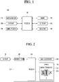
- FIG. 1 illustrates an AI device according to an embodiment of the present disclosure.
- the artificial intelligence device 100 may be referred to as a terminal 100.
- the AI device 100 may be implemented by a stationary device or a mobile device, such as a TV, a projector, a mobile phone, a smartphone, a desktop computer, a notebook, a digital broadcasting terminal, a personal digital assistant (PDA), a portable multimedia player (PMP), a navigation device, a tablet PC, a wearable device, a set-top box (STB), a DMB receiver, a radio, a washing machine, a refrigerator, a desktop computer, a digital signage, a robot, a vehicle, and the like.
- a stationary device or a mobile device such as a TV, a projector, a mobile phone, a smartphone, a desktop computer, a notebook, a digital broadcasting terminal, a personal digital assistant (PDA), a portable multimedia player (PMP), a navigation device, a tablet PC, a wearable device, a set-top box (STB), a DMB receiver, a radio, a washing machine, a refrigerator, a desktop computer,
- the AI device 100 may include a communication unit 110, an input unit 120, a learning processor 130, a sensing unit 140, an output unit 150, a memory 170, and a processor 180.
- the communication unit 110 may transmit and receive data to and from external devices such as other AI devices 100a to 100e and the AI server 200 by using wire/wireless communication technology.
- the communication unit 110 may transmit and receive sensor information, a user input, a learning model, and a control signal to and from external devices.
- the communication technology used by the communication unit 110 includes GSM (Global System for Mobile communication), CDMA (Code Division Multi Access), LTE (Long Term Evolution), 5G, WLAN (Wireless LAN), Wi-Fi (Wireless-Fidelity), Bluetooth TM , RFID (Radio Frequency Identification), Infrared Data Association (IrDA), ZigBee, NFC (Near Field Communication), and the like.
- GSM Global System for Mobile communication
- CDMA Code Division Multi Access
- LTE Long Term Evolution
- 5G Fifth Generation
- WLAN Wireless LAN
- Wi-Fi Wireless-Fidelity
- Bluetooth TM Bluetooth TM
- RFID Radio Frequency Identification
- IrDA Infrared Data Association
- ZigBee ZigBee
- NFC Near Field Communication
- the input unit 120 may acquire various kinds of data.
- the input unit 120 may include a camera for inputting a video signal, a microphone for receiving an audio signal, and a user input unit for receiving information from a user.
- the camera or the microphone may be treated as a sensor, and the signal acquired from the camera or the microphone may be referred to as sensing data or sensor information.
- the input unit 120 may acquire a learning data for model learning and an input data to be used when an output is acquired by using learning model.
- the input unit 120 may acquire raw input data.
- the processor 180 or the learning processor 130 may extract an input feature by preprocessing the input data.
- the learning processor 130 may learn a model composed of an artificial neural network by using learning data.
- the learned artificial neural network may be referred to as a learning model.
- the learning model may be used to an infer result value for new input data rather than learning data, and the inferred value may be used as a basis for determination to perform a certain operation.
- the learning processor 130 may perform AI processing together with the learning processor 240 of the AI server 200.
- the learning processor 130 may include a memory integrated or implemented in the AI device 100.
- the learning processor 130 may be implemented by using the memory 170, an external memory directly connected to the AI device 100, or a memory held in an external device.
- the sensing unit 140 may acquire at least one of internal information about the AI device 100, ambient environment information about the AI device 100, and user information by using various sensors.
- Examples of the sensors included in the sensing unit 140 may include a proximity sensor, an illuminance sensor, an acceleration sensor, a magnetic sensor, a gyro sensor, an inertial sensor, an RGB sensor, an IR sensor, a fingerprint recognition sensor, an ultrasonic sensor, an optical sensor, a microphone, a lidar, and a radar.
- a proximity sensor an illuminance sensor, an acceleration sensor, a magnetic sensor, a gyro sensor, an inertial sensor, an RGB sensor, an IR sensor, a fingerprint recognition sensor, an ultrasonic sensor, an optical sensor, a microphone, a lidar, and a radar.
- the output unit 150 may generate an output related to a visual sense, an auditory sense, or a haptic sense.
- the output unit 150 may include a display unit for outputting time information, a speaker for outputting auditory information, and a haptic module for outputting haptic information.
- the memory 170 may store data that supports various functions of the AI device 100.
- the memory 170 may store input data acquired by the input unit 120, learning data, a learning model, a learning history, and the like.
- the processor 180 may determine at least one executable operation of the AI device 100 based on information determined or generated by using a data analysis algorithm or a machine learning algorithm.
- the processor 180 may control the components of the AI device 100 to execute the determined operation.
- the processor 180 may request, search, receive, or utilize data of the learning processor 130 or the memory 170.
- the processor 180 may control the components of the AI device 100 to execute the predicted operation or the operation determined to be desirable among the at least one executable operation.
- the processor 180 may generate a control signal for controlling the external device and may transmit the generated control signal to the external device.
- the processor 180 may acquire intention information for the user input and may determine the user's requirements based on the acquired intention information.
- the processor 180 may acquire the intention information corresponding to the user input by using at least one of a speech to text (STT) engine for converting speech input into a text string or a natural language processing (NLP) engine for acquiring intention information of a natural language.
- STT speech to text
- NLP natural language processing
- At least one of the STT engine or the NLP engine may be configured as an artificial neural network, at least part of which is learned according to the machine learning algorithm. At least one of the STT engine or the NLP engine may be learned by the learning processor 130, may be learned by the learning processor 240 of the AI server 200, or may be learned by their distributed processing.
- the processor 180 may collect history information including the operation contents of the AI apparatus 100 or the user's feedback on the operation and may store the collected history information in the memory 170 or the learning processor 130 or transmit the collected history information to the external device such as the AI server 200.
- the collected history information may be used to update the learning model.
- the processor 180 may control at least part of the components of AI device 100 so as to drive an application program stored in memory 170. Furthermore, the processor 180 may operate two or more of the components included in the AI device 100 in combination so as to drive the application program.
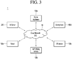
- FIG. 2 is a diagram illustrating an AI server according to an embodiment of the present disclosure.
- the AI server 200 may refer to a device that learns an artificial neural network by using a machine learning algorithm or uses a learned artificial neural network.
- the AI server 200 may include a plurality of servers to perform distributed processing, or may be defined as a 5G network. At this time, the AI server 200 may be included as a partial configuration of the AI device 100, and may perform at least part of the AI processing together.
- the AI server 200 may include a communication unit 210, a memory 230, a learning processor 240, a processor 260, and the like.
- the communication unit 210 can transmit and receive data to and from an external device such as the AI device 100.
- the memory 230 may include a model storage unit 231.
- the model storage unit 231 may store a learning or learned model (or an artificial neural network 231a) through the learning processor 240.
- the learning processor 240 may learn the artificial neural network 231a by using the learning data.
- the learning model may be used in a state of being mounted on the AI server 200 of the artificial neural network, or may be used in a state of being mounted on an external device such as the AI device 100.
- the learning model may be implemented in hardware, software, or a combination of hardware and software. If all or part of the learning models are implemented in software, one or more instructions that constitute the learning model may be stored in memory 230.
- the processor 260 may infer the result value for new input data by using the learning model and may generate a response or a control command based on the inferred result value.
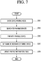
- FIG. 3 a diagram illustrating an AI system according to an embodiment of the present disclosure.
- an AI server 200 a robot 100a, a self-driving vehicle 100b, an XR device 100c, a smartphone 100d, or a home appliance 100e is connected to a cloud network 10.
- the robot 100a, the self-driving vehicle 100b, the XR device 100c, the smartphone 100d, or the home appliance 100e, to which the AI technology is applied, may be referred to as AI devices 100a to 100e.
- the cloud network 10 may refer to a network that forms part of a cloud computing infrastructure or exists in a cloud computing infrastructure.
- the cloud network 10 may be configured by using a 3G network, a 4G or LTE network, or a 5G network.
- the devices 100a to 100e and 200 configuring the AI system 1 may be connected to each other through the cloud network 10.
- each of the devices 100a to 100e and 200 may communicate with each other through a base station, but may directly communicate with each other without using a base station.
- the AI server 200 may include a server that performs AI processing and a server that performs operations on big data.
- the AI server 200 may be connected to at least one of the AI devices constituting the AI system 1, that is, the robot 100a, the self-driving vehicle 100b, the XR device 100c, the smartphone 100d, or the home appliance 100e through the cloud network 10, and may assist at least part of AI processing of the connected AI devices 100a to 100e.
- the AI server 200 may learn the artificial neural network according to the machine learning algorithm instead of the AI devices 100a to 100e, and may directly store the learning model or transmit the learning model to the AI devices 100a to 100e.
- the AI server 200 may receive input data from the AI devices 100a to 100e, may infer the result value for the received input data by using the learning model, may generate a response or a control command based on the inferred result value, and may transmit the response or the control command to the AI devices 100a to 100e.
- the AI devices 100a to 100e may infer the result value for the input data by directly using the learning model, and may generate the response or the control command based on the inference result.
- the AI devices 100a to 100e illustrated in Fig. 3 may be regarded as a specific embodiment of the AI device 100 illustrated in Fig. 1 .
- the robot 100a may be implemented as a guide robot, a carrying robot, a cleaning robot, a wearable robot, an entertainment robot, a pet robot, an unmanned flying robot, or the like.
- the robot 100a may include a robot control module for controlling the operation, and the robot control module may refer to a software module or a chip implementing the software module by hardware.
- the robot 100a may acquire state information about the robot 100a by using sensor information acquired from various kinds of sensors, may detect (recognize) surrounding environment and objects, may generate map data, may determine the route and the travel plan, may determine the response to user interaction, or may determine the operation.
- the robot 100a may use the sensor information acquired from at least one sensor among the lidar, the radar, and the camera so as to determine the travel route and the travel plan.
- the robot 100a may perform the above-described operations by using the learning model composed of at least one artificial neural network.
- the robot 100a may recognize the surrounding environment and the objects by using the learning model, and may determine the operation by using the recognized surrounding information or object information.
- the learning model may be learned directly from the robot 100a or may be learned from an external device such as the AI server 200.
- the robot 100a may perform the operation by generating the result by directly using the learning model, but the sensor information may be transmitted to the external device such as the AI server 200 and the generated result may be received to perform the operation.
- the robot 100a may use at least one of the map data, the object information detected from the sensor information, or the object information acquired from the external apparatus to determine the travel route and the travel plan, and may control the driving unit such that the robot 100a travels along the determined travel route and travel plan.
- the map data may include object identification information about various objects arranged in the space in which the robot 100a moves.
- the map data may include object identification information about fixed objects such as walls and doors and movable objects such as pollen and desks.
- the object identification information may include a name, a type, a distance, and a position.
- the robot 100a may perform the operation or travel by controlling the driving unit based on the control/interaction of the user. At this time, the robot 100a may acquire the intention information of the interaction due to the user's operation or speech utterance, and may determine the response based on the acquired intention information, and may perform the operation.
- the self-driving vehicle 100b may be implemented as a mobile robot, a vehicle, an unmanned flying vehicle, or the like.
- the self-driving vehicle 100b may include a self-driving control module for controlling a self-driving function, and the self-driving control module may refer to a software module or a chip implementing the software module by hardware.
- the self-driving control module may be included in the self-driving vehicle 100b as a component thereof, but may be implemented with separate hardware and connected to the outside of the self-driving vehicle 100b.
- the self-driving vehicle 100b may acquire state information about the self-driving vehicle 100b by using sensor information acquired from various kinds of sensors, may detect (recognize) surrounding environment and objects, may generate map data, may determine the route and the travel plan, or may determine the operation.
- the self-driving vehicle 100b may use the sensor information acquired from at least one sensor among the lidar, the radar, and the camera so as to determine the travel route and the travel plan.
- the self-driving vehicle 100b may recognize the environment or objects for an area covered by a field of view or an area over a certain distance by receiving the sensor information from external devices, or may receive directly recognized information from the external devices.
- the self-driving vehicle 100b may perform the above-described operations by using the learning model composed of at least one artificial neural network.
- the self-driving vehicle 100b may recognize the surrounding environment and the objects by using the learning model, and may determine the traveling movement line by using the recognized surrounding information or object information.
- the learning model may be learned directly from the self-driving vehicle 100a or may be learned from an external device such as the AI server 200.
- the self-driving vehicle 100b may perform the operation by generating the result by directly using the learning model, but the sensor information may be transmitted to the external device such as the AI server 200 and the generated result may be received to perform the operation.
- the self-driving vehicle 100b may use at least one of the map data, the object information detected from the sensor information, or the object information acquired from the external apparatus to determine the travel route and the travel plan, and may control the driving unit such that the self-driving vehicle 100b travels along the determined travel route and travel plan.
- the map data may include object identification information about various objects arranged in the space (for example, road) in which the self-driving vehicle 100b travels.
- the map data may include object identification information about fixed objects such as street lamps, rocks, and buildings and movable objects such as vehicles and pedestrians.
- the object identification information may include a name, a type, a distance, and a position.
- the self-driving vehicle 100b may perform the operation or travel by controlling the driving unit based on the control/interaction of the user. At this time, the self-driving vehicle 100b may acquire the intention information of the interaction due to the user's operation or speech utterance, and may determine the response based on the acquired intention information, and may perform the operation.
- the XR device 100c may be implemented by a head-mount display (HMD), a head-up display (HUD) provided in the vehicle, a television, a mobile phone, a smartphone, a computer, a wearable device, a home appliance, a digital signage, a vehicle, a fixed robot, a mobile robot, or the like.
- HMD head-mount display
- HUD head-up display
- the XR device 100c may analyzes three-dimensional point cloud data or image data acquired from various sensors or the external devices, generate position data and attribute data for the three-dimensional points, acquire information about the surrounding space or the real object, and render to output the XR object to be output. For example, the XR device 100c may output an XR object including the additional information about the recognized object in correspondence to the recognized object.
- the XR device 100c may perform the above-described operations by using the learning model composed of at least one artificial neural network. For example, the XR device 100c may recognize the real object from the three-dimensional point cloud data or the image data by using the learning model, and may provide information corresponding to the recognized real object.
- the learning model may be directly learned from the XR device 100c, or may be learned from the external device such as the AI server 200.
- the XR device 100c may perform the operation by generating the result by directly using the learning model, but the sensor information may be transmitted to the external device such as the AI server 200 and the generated result may be received to perform the operation.
- the robot 100a to which the AI technology and the self-driving technology are applied, may be implemented as a guide robot, a carrying robot, a cleaning robot, a wearable robot, an entertainment robot, a pet robot, an unmanned flying robot, or the like.
- the robot 100a to which the AI technology and the self-driving technology are applied, may refer to the robot itself having the self-driving function or the robot 100a interacting with the self-driving vehicle 100b.
- the robot 100a having the self-driving function may collectively refer to a device that moves for itself along the given movement line without the user's control or moves for itself by determining the movement line by itself.
- the robot 100a and the self-driving vehicle 100b having the self-driving function may use a common sensing method so as to determine at least one of the travel route or the travel plan.
- the robot 100a and the self-driving vehicle 100b having the self-driving function may determine at least one of the travel route or the travel plan by using the information sensed through the lidar, the radar, and the camera.
- the robot 100a that interacts with the self-driving vehicle 100b exists separately from the self-driving vehicle 100b and may perform operations pairing with the self-driving function of the self-driving vehicle 100b or pairing with the user who rides on the self-driving vehicle 100b.
- the robot 100a interacting with the self-driving vehicle 100b may control or assist the self-driving function of the self-driving vehicle 100b by acquiring sensor information on behalf of the self-driving vehicle 100b and providing the sensor information to the self-driving vehicle 100b, or by acquiring sensor information, generating environment information or object information, and providing the information to the self-driving vehicle 100b.
- the robot 100a interacting with the self-driving vehicle 100b may monitor the user boarding the self-driving vehicle 100b, or may control the function of the self-driving vehicle 100b through the interaction with the user. For example, when it is determined that the driver is in a drowsy state, the robot 100a may activate the self-driving function of the self-driving vehicle 100b or assist the control of the driving unit of the self-driving vehicle 100b.
- the function of the self-driving vehicle 100b controlled by the robot 100a may include not only the self-driving function but also the function provided by the navigation system or the audio system provided in the self-driving vehicle 100b.
- the robot 100a that interacts with the self-driving vehicle 100b may provide information or assist the function to the self-driving vehicle 100b outside the self-driving vehicle 100b.
- the robot 100a may provide traffic information including signal information and the like, such as a smart signal, to the self-driving vehicle 100b, and automatically connect an electric charger to a charging port by interacting with the self-driving vehicle 100b like an automatic electric charger of an electric vehicle.
- the robot 100a to which the AI technology and the XR technology are applied, may be implemented as a guide robot, a carrying robot, a cleaning robot, a wearable robot, an entertainment robot, a pet robot, an unmanned flying robot, a drone, or the like.
- the robot 100a to which the XR technology is applied, may refer to a robot that is subjected to control/interaction in an XR image.
- the robot 100a may be separated from the XR device 100c and interwork with each other.
- the robot 100a When the robot 100a, which is subjected to control/interaction in the XR image, may acquire the sensor information from the sensors including the camera, the robot 100a or the XR device 100c may generate the XR image based on the sensor information, and the XR device 100c may output the generated XR image.
- the robot 100a may operate based on the control signal input through the XR device 100c or the user's interaction.
- the user can confirm the XR image corresponding to the time point of the robot 100a pairing remotely through the external device such as the XR device 100c, adjust the self-driving travel path of the robot 100a through interaction, control the operation or driving, or confirm the information about the surrounding object.
- the external device such as the XR device 100c
- the self-driving vehicle 100b to which the AI technology and the XR technology are applied, may be implemented as a mobile robot, a vehicle, an unmanned flying vehicle, or the like.
- the self-driving driving vehicle 100b may refer to a self-driving vehicle having a means for providing an XR image or a self-driving vehicle that is subjected to control/interaction in an XR image.
- the self-driving vehicle 100b that is subjected to control/interaction in the XR image may be distinguished from the XR device 100c and interwork with each other.
- the self-driving vehicle 100b having the means for providing the XR image may acquire the sensor information from the sensors including the camera and output the generated XR image based on the acquired sensor information.
- the self-driving vehicle 100b may include an HUD to output an XR image, thereby providing a passenger with a real object or an XR object corresponding to an object in the screen.
- the self-driving vehicle 100b may output XR objects corresponding to objects such as a lane, another vehicle, a traffic light, a traffic sign, a two-wheeled vehicle, a pedestrian, a building, and the like.
- the self-driving vehicle 100b When the self-driving vehicle 100b, which is subjected to control/interaction in the XR image, may acquire the sensor information from the sensors including the camera, the self-driving vehicle 100b or the XR device 100c may generate the XR image based on the sensor information, and the XR device 100c may output the generated XR image.
- the self-driving vehicle 100b may operate based on the control signal input through the external device such as the XR device 100c or the user's interaction.
- FIG. 4 is a block diagram illustrating an AI device according to an embodiment of the present disclosure.
- the communication unit 110 may also be referred to as a communication modem or a communication circuit.
- the input unit 120 may be referred to as an input interface.
- the output unit 150 may be referred to as an output interface.
- the input unit 120 may include a camera 121 for inputting an image signal, a microphone 122 for receiving an audio signal, and a user input unit 123 for receiving information from a user.
- the speech data or image data collected by the input unit 120 may be analyzed and processed as a control command of the user.
- the input unit 120 is for inputting image information (or signal), audio information (or signal), data, or information input from a user.
- the AI device 100 may include one or a plurality of cameras 121.
- the camera 121 processes image frames such as still images or moving images obtained by an image sensor in a video call mode or a photographing mode.
- the processed image frames may be displayed on the display unit 151 or stored in the memory 170.
- the microphone 122 processes external sound signals as electrical speech data.
- the processed speech data may be utilized in various ways according to a function (or running application program) being performed in the AI device 100. Meanwhile, various noise reduction algorithms may be applied in the microphone 122 to remove noise occurring in the process of receiving an external sound signal.
- the user input unit 123 is for receiving information from a user.
- the processor 180 may control the operation of the AI device 100 to correspond to the input information when the information is inputted through the user input unit 123.
- the user input unit 123 may include mechanical input means (or a mechanical key, for example, a button, a dome switch, a jog wheel, or a jog switch located at the front/rear or side of the AI device 100) and touch input means.
- the touch input means may include a virtual key, a soft key, or a visual key displayed on the touch screen through software processing, or a touch key disposed in the other portion than the touch screen.
- the sensing unit 140 may be referred to as a sensor unit.
- the output unit 150 may include at least one of a display unit 151, a sound output unit 152, a haptic module 153, and an optical output unit 154.
- the display unit 151 displays (outputs) information processed by the AI device 100.
- the display unit 151 may display execution screen information of an application program running on the AI device 100, or UI (User Interface) or Graphic User Interface (GUI) information according to the execution screen information.
- UI User Interface
- GUI Graphic User Interface
- the display unit 151 may implement a touch screen in such a manner that the display unit 151 forms a layer structure with or is integrally formed with a touch sensor.
- a touch screen may function as a user input unit 123 that provides an input interface between the AI device 100 and the user and may provide an output interface between the terminal 100 and the user at the same time.
- the sound output unit 152 may output audio data received from the communication unit 110 or stored in the memory 170 in call signal reception, a call mode or a recording mode, a speech recognition mode, a broadcast reception mode, or the like.
- the sound output unit 152 may include at least one of a receiver, a speaker, and a buzzer.
- the haptic module 153 generates various tactile effects that a user is able to feel.
- a representative example of the tactile effect generated by the haptic module 153 may be vibration.
- the optical output unit 154 outputs a signal for notifying occurrence of an event by using light of a light source of the AI device 100.
- Examples of events generated by the AI device 100 may include message reception, call signal reception, a missed call, an alarm, schedule notification, email reception, and information reception through an application, and the like.
- FIG. 5 is a block diagram illustrating an artificial intelligence system 1 according to an embodiment of the present disclosure.
- the artificial intelligence system 1 may include an artificial intelligence device 100, a speech to text (STT, Speech To Text) server 300, a natural language processing (NLP) server 400 and a speech synthesis server 500.
- STT Speech to Text
- NLP natural language processing
- the artificial intelligence device 100 may transmit speech data to the STT server 300.
- the STT server 300 may convert the speech data received from the artificial intelligence device 100 into text data.
- the NLP server 400 may receive text data from the STT server 300.
- the NLP server 400 may perform intention analysis on the text data based on the received text data.
- the NLP server 400 may transmit intention analysis information indicating a result of performing the intention analysis to the artificial intelligence device 100 or the speech synthesis server 500.
- the speech synthesis server 500 may generate a synthesized speech reflecting a user's intention based on the intention analysis information, and transmit the generated synthesized speech to the artificial intelligence device 100.
- the STT server 300 may increase the accuracy of speech-text conversion by using a language model.
- the language model may refer to a model capable of calculating the probability of a sentence or calculating probability that the next word will appear when previous words are given.
- the language model may include probabilistic language models such as a Unigram model, a Bigram model, an N-gram model, and the like.
- the unigram model is a model assuming that the uses of all words are completely independent of each other, and a model that calculates the probability of a string of words as the product of the probabilities of the words.
- the bigram model is a model assuming that the use of a word depends only on one previous word.
- the N-gram model is a model assuming that the use of a word depends on the previous (n-1) words.
- the STT server 300 may determine whether the text data converted from speech data is properly converted by using the language model, thereby increasing the accuracy of the conversion from the speech data to the text data.
- the NLP server 400 may generate the intention analysis information by sequentially performing a morpheme analysis operation, a syntax analysis operation, a dialogue act analysis operation, and a dialogue processing operation on the text data.
- the morpheme analysis operation is an operation of classifying text data corresponding to speech uttered by the user into morpheme units, which are the smallest units having meaning, and determining which part of speech each classified morpheme has.
- the syntax analysis operation is an operation of classifying the text data into a noun phrase, a verb phrase, an adjective phrase, or the like using a result of the morpheme analysis operation, and determining a relation between the phrases. Through the syntax analysis operation, the subject, object, and modifiers of the speech spoken by the user may be determined.
- the dialogue act analysis operation is an operation of analyzing the intention of the speech uttered by the user using the result of the syntax analysis operation.
- the dialogue act analysis operation is an operation of determining the intent of the sentence, such as whether the user asks a question, makes a request, or expresses a simple emotion.
- the dialog processing operation is an operation for determining whether to answer the user's utterance, respond to the utterance, or ask a question inquiring additional information, using a result of the speech act analysis operation.
- the NLP server 400 may generate intention analysis information including one or more of an answer to the intention uttered by the user, and a response to the intention and an additional information inquiry.
- the NLP server 400 may receive text data from the artificial intelligence device 100.
- the artificial intelligence device 100 may convert speech data into text data and transmit the converted text data to the NLP server 400.
- the speech synthesis server 500 may generate a synthesized speech by combining pieces of pre-stored speech data.
- the speech synthesis server 500 may record the speech of a person selected as a model, and divide the recorded speech into syllables or words.
- the speech synthesis server 500 may store the speech divided in units of syllables or words in an internal or external database.
- the speech synthesis server 500 may search for syllables or words corresponding to given text data from the database and synthesize a combination of the syllables or the words searched to generate a synthesized speech.
- the speech synthesis server 500 may store a plurality of speech language groups respectively corresponding to a plurality of languages.
- the speech synthesis server 500 may include a first speech language group recorded in Korean, and a second speech language group recorded in English.
- the speech synthesis server 500 may translate text data of a first language into text of a second language, and generate a synthesized speech corresponding to the translated text of the second language by using a second speech language group.
- the artificial intelligence system 1 may further include an artificial intelligence server 200.
- the artificial intelligence server 200 may allow at least one of an STT engine used in the STT server 300, an NLP engine used in the NLP server 400, and a speech synthesis engine used in the speech synthesis server 500 to be learned. That is, at least one of the STT server 300, the NLP server 400, and the speech synthesis server 500 may use models or engines trained in the artificial intelligence server 200.
- the artificial intelligence device 100, the STT server 300, the NLP server 400, and the speech synthesis server 500 are illustrated as being separate from each other, but the present disclosure is not limited thereto.
- some of the artificial intelligence server 200, the STT server 300, the NLP server 400, or the speech synthesis server 500 may be configured as one server.
- some of the STT server 300, the NLP server 400 or the speech synthesis server 500 may be included in the artificial intelligence device 100, which implies that the artificial intelligence device 100 performs functions of the STT server 300, the NLP server 400 or the speech synthesis server 500.
- FIG. 6 is a diagram illustrating artificial intelligence systems 1 that provide a device control function based on pairing between devices according to various embodiments of the present disclosure.
- the artificial intelligence system 1 essentially includes the artificial intelligence device 100, and may optionally further include at least one or more of an artificial intelligence server 200 and an IoT (Internet of Things) device 600.
- an artificial intelligence server 200 and an IoT (Internet of Things) device 600.
- IoT Internet of Things
- the artificial intelligence system 1 that provides a device control function based on inter-device pairing may include at least two or more of artificial intelligence devices 100 or IoT devices 600 which are targets for paring in order to provide a device control function. That is, the artificial intelligence system 1 may include only a plurality of artificial intelligence devices 100, or may include one or more artificial intelligence devices 100 and one or more IoT devices 600.
- At least some of the artificial intelligence device 100, the artificial intelligence server 200, or the IoT device 600 included in the artificial intelligence system 1 may communicate with each other based on wired/wireless communication technology. All of the artificial intelligence device 100, the artificial intelligence server 200, or the IoT device 600 included in the artificial intelligence system 1 may directly communicate with each other, or some thereof may directly communicate with each other. In particular, the artificial intelligence device 100 or the IoT device 600 included in the artificial intelligence system 1 may directly or indirectly communicate with each other.
- Two devices communicating with each other indirectly may mean that the two devices communicate with each other through at least one or more third devices (e.g., artificial intelligence device 100, artificial intelligence server 200, or IoT device 600).
- two devices communicating with each other directly may mean that the two devices directly communicate with each other through or without a communication-dedicated device (e.g., a base station, a router, etc.).
- FIG. 6 (a) and (b) show artificial intelligence systems 1 including a first artificial intelligence device 100_1, a second artificial intelligence device 100_2, an artificial intelligence server 200, and an IoT device 600, and (c) shows an artificial intelligence system 1 including the first artificial intelligence device 100_1, the second artificial intelligence device 100_2, and the IoT device 600.
- the first artificial intelligence device 100_1, the second artificial intelligence device 100_2, the artificial intelligence server 200 and the IoT device 600 may directly communicate with one another.
- the first artificial intelligence device 100_1, the artificial intelligence server 200 and the IoT device 600 may communicate directly with one another, and the second artificial intelligence device 100_2 may directly communicate with the first artificial intelligence device 100_1. Accordingly, the second artificial intelligence device 100_2 may communicate with the IoT device 600 only through the first artificial intelligence device 100_1.
- the first artificial intelligence device 100_1 may directly communicate with the second artificial intelligence device 100_2 and the IoT device 600, and the second artificial intelligence device 100_2 may directly communicate with the first artificial intelligence device 100_1, and the IoT device 600 may directly communicate with the first artificial intelligence device 100_1. Accordingly, the second artificial intelligence device 100_2 and the IoT device 600 may indirectly communicate with each other through the first artificial intelligence device 100_1.
- the artificial intelligence device 100 or the IoT device 600 included in the artificial intelligence system 1 may directly or indirectly communicate with each other.
- the artificial intelligence device 100 included in the artificial intelligence system 1 may perform inter-device pairing with another artificial intelligence device 100 or the IoT device 600 through communication, and store information on the paired devices. Further, when the artificial intelligence device 100 is connected to the artificial intelligence server 200, the artificial intelligence device 100 may transmit information on the paired devices to the artificial intelligence server 200.
- the information on the paired devices may include at least one or more of device identification information, a communication method, and a pairing platform which are associated with devices that are paired with each other.
- the information on the paired devices may be stored in the form of a table, which may be referred to as a pairing information table.
- the pairing information table may be stored in the memory 170 of the artificial intelligence device 100 or the memory 230 of the artificial intelligence server 200.
- the device identification information may include a device serial number corresponding to each device (such as an artificial intelligence device or an IoT device).
- the communication method refers to a communication method of paired devices, and may include Bluetooth, Wi-Fi, cellular network, Ethernet, infrared communication, and the like.
- the pairing platform may refer to a service platform or a command platform used by paired devices to interact each other, and may include a value indicating a corresponding platform, a list of APIs, grammar rules, and the like.
- the pairing information table for the first artificial intelligence device 100_1 shown in (b) of FIG. 6 may include pairing information of the first artificial intelligence device 100_1.
- a first item of the pairing information table for the first artificial intelligence device 100_1 shown in in (b) of FIG. 6 may be pairing information between the first artificial intelligence device 100_1 and the second artificial intelligence device 100_2, and a second item may be pairing information between the first artificial intelligence device 100_1 and the IoT device 600.
- a third item of the pairing information table for the first artificial intelligence device 100_1 shown in (b) of FIG. 6 may be pairing information between the first artificial intelligence device 100_1 and the artificial intelligence server 200.
- the artificial intelligence server 200 may receive the pairing information table from the connected artificial intelligence device 100 and manage the pairing information table received from several artificial intelligence devices 100.
- the artificial intelligence device 100, the artificial intelligence server 200, or the IoT device 600 included in the artificial intelligence system 1 may share their pairing information tables among connected devices.
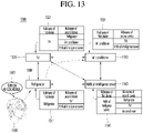
- the second artificial intelligence device 100_2 may share its own pairing information table (the second pairing information table) with the paired first artificial intelligence device 100_1, and the first artificial intelligence device 100_1 may store and manage its own pairing information table (first pairing information table) as well as the pairing information table (second pairing information table) received from the second artificial intelligence device 100_2.
- the artificial intelligence device 100 may establish a connection path based on at least a part of its own pairing information table or the pairing information table received from another device, generate a command for performing a specific operation in consideration of the determined connection path, and transmit the generated command to the target device via the determined connection path to allow the target device to perform the specific operation.
- a target device e.g., another artificial intelligence device 100, the artificial intelligence server 200, the IoT device 600, or the like
- the artificial intelligence device 100 may establish a connection path based on at least a part of its own pairing information table or the pairing information table received from another device, generate a command for performing a specific operation in consideration of the determined connection path, and transmit the generated command to the target device via the determined connection path to allow the target device to perform the specific operation.
- the artificial intelligence device 100 included in the artificial intelligence system 1 does not share its pairing information table with other artificial intelligence devices 100 or IoT devices 600, and share its own pairing information table only with the artificial intelligence server 200.
- the artificial intelligence device 100 may query another device whether the artificial intelligence device 100 connects to a desired target device, and receive connectivity information or a connection path from the other device to indirectly use a pairing information table of the other device.
- the artificial intelligence device 100 may establish a connection path based on at least a part of its own pairing information table or connectivity information received from paired other devices, generate a command for performing a specific operation in consideration of the determined connection path, and transmit the generated command to the target device via the determined connection path to allow the target device to perform the specific operation.
- a target device e.g., another artificial intelligence device 100, the artificial intelligence server 200, the IoT device 600, or the like
- the artificial intelligence device 100 may establish a connection path based on at least a part of its own pairing information table or connectivity information received from paired other devices, generate a command for performing a specific operation in consideration of the determined connection path, and transmit the generated command to the target device via the determined connection path to allow the target device to perform the specific operation.
- the generated command may include transmitting device information and receiving device information. Also, when the transmitting device communicates with the receiving device through another device, that is, when another device exists between the transmitting device and the receiving device on a connection path, the generated command may further include waypoint device information.
- the transmitting device may refer to the artificial intelligence device 100 that generates a command
- the receiving device may refer to a target device that performs a specific operation or a destination device that is to receive the generated command and perform operation.
- the artificial intelligence device 100 may receive the user's uttered speech, determine an operation with the target device or the receiving device by determining intention of the received user's uttered speech, and determine a connection path to the receiving device using the pairing information table, and generate and transmit a command for allowing the target device to perform the operation based on the determined connection path and the determined operation.
- the user's uttered speech may include a starting word for calling the transmitting device, a name or nickname indicating the receiving device, a command indicating an operation to be performed by the receiving device, and the like.
- the starting word for calling the transmitting device may be a name or a nickname indicating the transmitting device, or may be a starting word set in a speech recognition platform installed in the transmitting device or used by the transmitting device.
- FIG. 7 is an operation flowchart illustrating a method of providing a device control function based on inter-device pairing according to an embodiment of the present disclosure.
- FIG. 7 illustrates an operation flowchart showing a method by which an artificial intelligence device 100 pairs with another device (e.g., another artificial intelligence device 100 or the IoT device 600) to provide a device control function based on inter-device pairing according to an embodiment of the present disclosure.
- another device e.g., another artificial intelligence device 100 or the IoT device 600
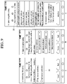
- the processor 180 of the artificial intelligence device 100 enters a device pairing mode (S701).
- the device pairing mode may refer to a mode in which the artificial intelligence device 100 attempts to pair with another artificial intelligence device 100 or the IoT device 600. Entering the device pairing mode may mean that the device pairing mode is activated.
- the processor 180 may enter the device pairing mode when a device pairing application is executed or a setting item for device pairing is entered.
- the processor 180 of the artificial intelligence device 100 searches for pairable devices through the communication unit 110 (S703).
- Searching for pairable devices may mean detecting a pairing request signal output from another device by using a communication technology available for inter-device pairing in the communication unit 110, or outputting a pairing request signal through the communication unit 110 and detecting the pairing request signal output from another device in response to the pairing request signal.
- the processor 180 of the artificial intelligence device 100 may pair with the found pairable device (S705).
- the processor 180 may output a pairable device list including a plurality of pairable devices through the display unit 151, and pair with a device selected by a user input through the input unit 120.
- the paired device may be referred to as a target device.
- the processor 180 may output a pairable device list including one pairable device through the display unit 151, or a notification asking whether to pair with one found pairable device and pair with the found pairable device based on a user input through the input unit 120.
- the processor 180 may obtain identification information, device name information, device type information, communication address information, and the like of a device found in a device pairing process.
- the identification information of the paired device may include a serial number of the paired device.
- the communication address information may include an IP address (Internet Protocol Address), a MAC address (Media Access Control Address), a Bluetooth address, and the like.
- the processor 180 of the artificial intelligence device 100 may set the name or nickname of the paired device (S707).
- the step (S707) of setting the name or nickname of the paired device may be selectively performed.
- the name or nickname of the paired device may be set based on a user input through the input unit 130, and the user input may include text or speech uttered by a user.
- the processor 180 of the artificial intelligence device 100 may update the pairing information table (S709).
- the pairing information table may include identification information, name, nickname, type information, communication method, pairing platform, and the like of the paired device.
- the pairing information table may include information associated with paired devices.
- the pairing information table may include pairing information on paired devices, and the processor 180 may update the pairing information table by adding the pairing information on a newly paired device to the pairing information table.
- the processor 180 of the artificial intelligence device 100 may transmit the updated pairing information table to the artificial intelligence server 200 or the paired device through the communication unit 110. Similarly, the processor 180 of the artificial intelligence device 100 may receive a pairing information table of another paired device from the artificial intelligence server 200 or the paired device through the communication unit 110.
- the device pairing method may not include a process of pairing a user's account with a device, but only include a process of performing inter-device pairing. Accordingly, in an embodiment of the present disclosure, there is an advantage that inter-device pairing is possible without being dependent on a specific user through pairing between devices.
- the order of the steps shown in FIG. 7 is only an example, and the present disclosure is not limited thereto. That is, according to an embodiment, the order of some of the steps shown in FIG. 7 may be reversed to be performed. In an embodiment, some of the steps shown in FIG. 7 may be performed in parallel. Also, only some of the steps shown in FIG. 7 may be performed.
- FIG. 7 illustrates one cycle of a method in which the artificial intelligence device 100 pairs with other devices, and the present disclosure is not limited thereto. That is, the steps shown in FIG. 7 may be repeatedly performed, and accordingly, the artificial intelligence device 100 may pair with several devices.
- FIG. 8 is a diagram illustrating a device pairing interface for providing information on a paired device according to an embodiment of the present disclosure.
- the processor 180 of the artificial intelligence device 100 may provide a device pairing interface that provides information on a paired device through the display unit 151, and the device pairing interface may include a paired device list 811 indicating a currently paired device.
- the processor 180 may provide a device pairing interface including a paired device list 811 indicating the paired device ((a) of FIG. 8 ).
- the processor 180 may provide a device pairing interface including a notification 821 indicating that there is no paired device or an empty paired device list ((b) of FIG. 8 ).
- FIG. 9 is a diagram illustrating a device pairing interface pairing with a new device according to an embodiment of the present disclosure.
- the processor 180 of the artificial intelligence device 100 may provide a device pairing interface that pairs with a new device through the display unit 151, and the device pairing interface may include at least one or more of a pairable device list 911, a name setting interface 921 for a paired device, and a paired device list 931.
- the processor 180 may search for pairable devices and provide a device pairing interface including the pairable device list 911 indicating the found pairable devices ((a) of FIG. 9 ). In addition, the processor 180 may pair with at least one of the pairable devices included in the pairable device list 911 based on a user input through the input unit 120.
- the processor 180 may provide the device pairing interface including the name setting interface 921 for setting a name of a paired device ((b) of FIG. 9 ).
- the set name of the paired device may refer to a nickname for calling the paired device by speech.
- a device named "my house air conditioner 2" may be set to "bedroom air conditioner", and in this case, the user may specify "my house air conditioner 2" by calling "bedroom air conditioner” with speech.
- the processor 180 may provide a device pairing interface including the paired device list 931 indicating the paired device ((c) of FIG. 9 ).
- FIGS. 7 to 9 illustrate a method by which the artificial intelligence device 100 directly pairs with another device and a device pairing interface according to the method, but the present disclosure is not limited thereto. That is, in an embodiment, pairing between the artificial intelligence device 100 and other devices may be performed through a terminal connected to the artificial intelligence device 100, and the device pairing interface may be provided on a display unit provided in the terminal. Similarly, the artificial intelligence device 100 may perform an operation such as setting whether to pair with another device or setting a nickname of a device to be paired based on a user input through an input unit of the terminal.
- FIG. 10 is an operation flowchart illustrating a method of providing a device control function based on inter-device pairing according to an embodiment of the present disclosure.
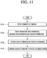
- the processor 180 of the artificial intelligence device 100 may receive a device use command from a user through the input unit 120 (S1001).
- the device use command may include a command for controlling an operation or state of a target device (or a receiving device) or a command for using a function of the target device.
- the device use command may be a command to control power or operation of the air conditioner, or a command to request status information of the air conditioner.
- the device use command may also be referred to as a device use request.
- the device use command may be input in the form of a speech uttered by a user, or may be input in the form of a touch on a device use interface or text.
- the processor 180 of the artificial intelligence device 100 may obtain transmitting device information, receiving device information, and operation information by using the device use command (S1003).
- the processor 180 may obtain the transmitting device information, the receiving device information and the operation information based on the device use command. Also, since the artificial intelligence device 100 functions as the transmitting device, the processor 180 may obtain the transmitting device information.
- the transmitting device information is information for specifying the artificial intelligence device 100 as a transmitting device, and may include a name or a serial number of the artificial intelligence device 100.
- the receiving device information is information for specifying a receiving device (or target device) performing an operation, and may include a name, title, nickname, serial number, and the like of the receiving device.
- the operation information may indicate an operation to be performed by the receiving device (or the target device).
- the processor 180 of the artificial intelligence device 100 may convert the uttered speech into text directly or through the artificial intelligence server 200, and perform a natural language processing (NLP) technique on the converted text to determine the user's intention.
- NLP natural language processing
- the processor 180 of the artificial intelligence device 100 may determine a connection path to the receiving device using the pairing information table (S1005).
- the connection path to the receiving device may mean a path for the artificial intelligence device 100 as a transmitting device to connect to the receiving device (or target device).
- the connection path may include only the artificial intelligence device 100 as the transmitting device and the receiving device.
- the connection path may sequentially include the artificial intelligence device 100 as the transmitting device, the intermediate device, and the receiving device, and such a connection path may mean that the artificial intelligence device 100 may be connected to the receiving device through the intermediate device.
- the processor 180 may identify paired devices by using the pairing information table stored in the memory 170, and may determine a connection path based the pairing information table.
- the memory 170 may merely store a pairing information table (hereinafter, referred to as a first pairing information table) of the artificial intelligence device 100, but also pairing information tables (hereinafter, referred to as a second pairing information table) of paired devices received from the paired devices.
- a pairing information table hereinafter, referred to as a first pairing information table
- a second pairing information table pairing information tables
- the processor 180 may determine whether a receiving device is included among directly-paired devices by using its own pairing information table (hereinafter, referred to as a first pairing information table) stored in the memory 170.
- a first pairing information table stored in the memory 170.
- the processor 180 may determine a connection path.
- the processor 180 may request a connection path from the transmitting device to the receiving device, from devices included in the first pairing information table that is, the directly-paired devices through the communication unit 110.
- the processor 180 may determine a connection path based on the received connection path.
- the directly-paired devices may determine a connection path in the same method as the artificial intelligence device 100.
- the processor 180 may request a connection path to the receiving device from the artificial intelligence server 200 through the communication unit 110.
- the processor 260 of the artificial intelligence server 200 may determine a connection path from the transmitting device to the receiving device using pairing information tables received from each device (such as the artificial intelligence device 100 or the IoT device 600), and transmit the determined connection path to the artificial intelligence device 100 through the communication unit 210.
- the processor 180 may determine the connection path from the transmitting device to the receiving device using it's own pairing information table (first pairing information table) stored in the memory 170 and pairing information tables of other devices (second pairing information tables).
- first pairing information table stored in the memory 170
- second pairing information tables pairing information tables of other devices
- the processor 180 of the artificial intelligence device 100 may determine whether there is a connection path to the receiving device (S1007).
- the processor 180 may determine that there is no connection path.
- the processor 180 of the artificial intelligence device 100 may output a notification indicating that the device use command cannot be performed, through the output unit 150 (S1009).
- connection path to the receiving device Since a case where there is no connection path to the receiving device means that the connection path to the receiving device cannot be determined, it may mean that the receiving device (or target device) to perform the device use command by the user input cannot be specified. Accordingly, since the processor 180 did not find a target for performing the device use command, the processor 180 may output a notification indicating that the device use command cannot be performed and terminate relevant procedure.
- the processor 180 of the artificial intelligence device 100 may generate a command for performing an operation corresponding to the device use command in the receiving device (S1011).
- the generated command may include transmitting device information, receiving device information and operation information. Furthermore, the generated command may further include the connection path.
- the processor 180 of the artificial intelligence device 100 may transmit the generated command according to the determined connection path through the communication unit 110 (S1013).
- the processor 180 may transmit the generated command to the receiving device through the communication unit 110.
- the processor 180 may transmit the generated command to an intermediate device directly paired with the artificial intelligence device 100 on the connection path through the communication unit 110.
- the order of the steps shown in FIG. 10 is only an example, and the present disclosure is not limited thereto. That is, according to an embodiment, the order of some of the steps shown in FIG. 10 may be reversed to be performed. Further, in an embodiment, some of the steps shown in FIG. 10 may be performed in parallel. Further, only some of the steps shown in FIG. 10 may be performed.
- FIG. 10 illustrates only one cycle of a method by which the artificial intelligence device 100 provides a device control function, and the present disclosure is not limited thereto. That is, the steps shown in FIG. 10 may be repeatedly performed, and accordingly, the artificial intelligence device 100 may perform control for an external device several times.
- FIG. 11 is an operation flowchart illustrating a method of providing a device control function based on inter-device pairing according to an embodiment of the present disclosure.
- the processor 180 of the artificial intelligence device 100 may receive a device use command from a user through the input unit 120 (S1101). This step corresponds to step S1001 of receiving the device use command shown in FIG. 10 .
- the processor 180 of the artificial intelligence device 100 may obtain transmitting device information, receiving device information, and operation information by using the device use command (S1103). This step corresponds to the step S1103 of obtaining the transmitting device information, the receiving device information and the operation information shown in FIG. 10 .
- the processor 180 of the artificial intelligence device 100 may generate a command for performing an operation corresponding to the device use command in the receiving device (S1105).
- the generated command may include transmitting device information, receiving device information and operation information.
- the generated command may include a command to transmit the generated command to the receiving device.
- the processor 180 of the artificial intelligence device 100 may transmit the generated command to the artificial intelligence server 200 through the communication unit 110 (S1107).
- the artificial intelligence server 200 may identify the receiving device in the command received from the artificial intelligence device 100, determine whether there is a connection path from the artificial intelligence device 100 as a transmitting device to the receiving device, and when there is a connection path, transmit the received command to the identified receiving device.
- the order of the steps shown in FIG. 11 is only an example, and the present disclosure is not limited thereto. That is, according to an embodiment, the order of some of the steps shown in FIG. 11 may be reversed to be performed. Further, in an embodiment, some of the steps shown in FIG. 11 may be performed in parallel. Further, only some of the steps shown in FIG. 11 may be performed.
- FIG. 11 illustrates only one cycle of a method by which the artificial intelligence device 100 provides a device control function, and the present disclosure is not limited thereto. That is, the steps shown in FIG. 11 may be repeatedly performed, and accordingly, the artificial intelligence device 100 may perform control for an external device several times.
- FIG. 12 is a diagram illustrating an example of a pairing information table according to an embodiment of the present disclosure.
- FIG. 12 may be a pairing information table of the first artificial intelligence device.
- a first artificial intelligence device and a second artificial intelligence device are paired with each other on the first platform, and the first artificial intelligence device and the second artificial intelligence device may communicate with each other via Wi-Fi.
- the first artificial intelligence device and a third artificial intelligence device are paired with each other on the first platform, and the first artificial intelligence device and the third artificial intelligence device may communicate with each other via Wi-Fi.
- the first artificial intelligence device and the IoT device are paired with each other on the second platform, and the first artificial intelligence device and the IoT device may communicate with each other via Bluetooth Low Energy (BLE).
- BLE Bluetooth Low Energy
- the first artificial intelligence device and the artificial intelligence server are paired with each other on the first platform, and the first artificial intelligence device and the artificial intelligence server may communicate with each other via Ethernet or Wi-Fi.
- the pairing information table may be updated in a situation in which a new device is paired or an existing paired device is disconnected.
- FIGS. 13 to 15 are diagrams illustrating artificial intelligence systems according to various embodiments of the present disclosure.
- an artificial intelligence system 1300 may include a refrigerator 1310 as a first artificial intelligence device, a TV 1320 as a second artificial intelligence device, and an air conditioner 1330 as a third artificial intelligence device, and an artificial intelligence server 1340.
- the refrigerator 1310 may be paired with the TV 1320 and the artificial intelligence server 1340.
- the TV 1320 may be paired with the refrigerator 1310, the air conditioner 1330, and the artificial intelligence server 1340.
- the air conditioner 1330 may be paired with the TV 1320 and the artificial intelligence server 1340. That is, the refrigerator 1310 is indirectly connected to the air conditioner 1330 through the TV 1320.
- pairing information tables 1311, 1321, and 1331 respectively stored in the devices 1310, 1320, 1330, and 1340 are shown in FIGS. 13 to 15 , only the nickname of the first device and the nickname of the second device are displayed among several items included in the illustrated pairing information table. That is, the pairing information table actually stored in each device may further include not only the items shown in FIGS. 13 to 15 , but also the name, identification information, pairing platform, communication method, and the like of of each device.
- a user 1360 may input a device use command for turning on the power of the air conditioner 1330 by uttering "Power on air conditioner" 1361 with respect to the refrigerator 1310.
- the refrigerator 1310 may analyze the user's intention to determine the refrigerator 1310 as a transmitting device, the keyword "air conditioner” as the receiving device information, and "power on” as the operation information. Since the refrigerator 1310 has not yet identified whether the keyword “air conditioner” for the receiving device obtained from the user's uttered speech indicates the air conditioner 1330 included in the artificial intelligence system 1300, the receiving device information may be determined only in the form of keyword “air conditioner”. For example, the refrigerator 1310 may determine “intent” item as "power on” in the intention information, and determine “device keyword", which is a sub item of "slot” item, as “air conditioner” as additional information. Since a device corresponding to "air conditioner” has not yet been identified, it is unclear whether “air conditioner” is a name or a nickname of a paired device, and therefore "air conditioner” may be classified as a device keyword item.
- FIG. 13 shows an embodiment in which each device 1310, 1320, 1330, or 1340 does not transmit its own pairing information table (first pairing information table) to other devices.
- a refrigerator 1310 may store only a pairing information table 1311 of the refrigerator 1310
- a TV 1320 may store only a pairing information table 1321 of the TV 1320
- an air conditioner 1330 may store only a pairing information table 1331 of the air conditioner 1330
- an artificial intelligence server 1340 may store only a pairing information table 1341 of the artificial intelligence server 1340.
- the refrigerator 1310 may determine whether there is a device corresponding to a keyword "air conditioner” among directly-paired devices based on the pairing information table 1311. However, since the refrigerator 1310 is not directly paired with the air conditioner 1330, the refrigerator 1310 may request a connection path to the device corresponding to the keyword "air conditioner” from the TV 1320 or the artificial intelligence server 1340 as a paired device included in the pairing information table 1311.
- the device corresponding to the keyword "air conditioner” may be determined as the air conditioner 1330.
- the TV 1320 may determine a connection path to the air conditioner 1330 as "TV->air conditioner” and transmit the connection path to the refrigerator 1310.
- the information transmitted by the TV 1320 to the refrigerator 1310 may further include information on the air conditioner 1330 as a receiving device and information on the TV 1320 as an intermediate device, in addition to the connection path.
- the refrigerator 1310 may recognize that the device corresponding to the keyword "air conditioner” is the air conditioner 1330 based on the information received from the TV 1320, and determine the connection path to the air conditioner 1330 as "refrigerator->TV-> air conditioner". In addition, the refrigerator 1310 may generate a command to turn on the power of the air conditioner 1330 in consideration of the determined connection path, and transmit the generated command to the TV 1320 according to the connection path.
- the transmitted command may include information on the refrigerator 1310 as a transmitting device, information on the air conditioner 1330 as a receiving device, "power on” as operation information and the like.
- the TV 1320 may transmit the command received from the refrigerator 1310 to the air conditioner 1330 based on the connection path included in the command received from the refrigerator 1310 or separately received from the refrigerator 1310.
- the air conditioner 1330 may perform an operation of turning on the power based on the received command.
- the refrigerator 1310 may perform a device use command associated with the air conditioner 1330 that is not directly paired, through the TV 1320.
- FIG. 14 shows an embodiment in which each device 1310, 1320, 1330, or 1340 transmits its own pairing information table (first pairing information table) to other devices.
- a refrigerator 1310, a TV 1320, an air conditioner 1330, and an artificial intelligence server 1340 may share a pairing information table with each other, and store a pairing information table 1411 including pairing information of various devices 1411, 1421, 1431, and 1441.
- the refrigerator 1310 may determine whether there is a device corresponding to keyword "air conditioner” among directly-paired devices based on the pairing information table 1411, and may determine that the device corresponding to the keyword "air conditioner” is the air conditioner 1330. In addition, the refrigerator 1310 may determine a connection path from the refrigerator 1310 to the air conditioner 1330 based on the stored pairing information table 1441 as "refrigerator - > TV -> air conditioner” and "refrigerator -> artificial intelligence server -> air conditioner”.
- the refrigerator 1310 may determine the connection path as one of "refrigerator->TV->air conditioner” and "refrigerator->artificial intelligence server->air conditioner” based on a preset communication protocol or a user input. In addition, the refrigerator 1310 may generate a command to turn on the power of the air conditioner 1330 in consideration of the determined connection path, and transmit the generated command to the TV 1320 or the artificial intelligence server 1340 according to the connection path.
- the transmitted command may include information on the refrigerator 1310 as a transmitting device, information on the air conditioner 1330 as a receiving device, "power on” as operation information and the like.
- the TV 1320 or the artificial intelligence server 1340 may transmit the command received from the refrigerator 1310 to the air conditioner 1330 based on the connection path included in the command received from the refrigerator 1310 or separately received from the refrigerator 1310.
- the air conditioner 1330 may perform an operation of turning on the power based on the received command.
- the refrigerator 1310 may perform a device use command associated with the air conditioner 1330 that is not directly paired, through the TV 1320 or the artificial intelligence server 1340.
- FIG. 15 shows an embodiment in which devices 1310, 1320, 1330 except for the artificial intelligence server 1340 transmit their own pairing information tables (first pairing information tables) to the artificial intelligence server 1340.
- the refrigerator 1310, the TV 1320 and the air conditioner 1330 share their pairing information tables with the artificial intelligence server 1340, and the artificial intelligence server 1340 may store a pairing information table 1541 including pairing information of the devices 1310, 1320, and 1330 paired with the artificial intelligence server 1340.
- the refrigerator 1310 may store only the pairing information table 1311 of the refrigerator 1310
- the TV 1320 may store only the pairing information table 1321 of the TV 1320
- the air conditioner 1330 may store only the pairing information table 1341 of the air conditioner 1330.
- the refrigerator 1310 may determine whether there is a device corresponding to a keyword "air conditioner” among directly-paired devices based on the pairing information table 1511. However, since the refrigerator 1310 is not directly paired with the air conditioner 1330, the refrigerator 1310 may request a connection path to the device corresponding to keyword "air conditioner” from the TV 1320 or the artificial intelligence server 1340 as a paired device included in the pairing information table 1311.
- the artificial intelligence server 1340 since the artificial intelligence server 1340 has obtained the pairing information table from each of the devices 1310, 1320 and 1330 unlike the embodiment shown in FIG. 13 , the artificial intelligence server 1340 may determine a connection path with the receiving device even when the artificial intelligence server 1340 does not communicate with the other devices 1310, 1320, and 1330.
- the TV 1320 similarly to FIG. 13 , the TV 1320 may set a connection path and serve as an intermediate device for transmitting a command from the refrigerator 1310 to the air conditioner 1330.
- the artificial intelligence server 1340 may identify that the nickname of the air conditioner 1330 is "air conditioner” based on the pairing information table 1541, and determine a device corresponding to the keyword "air conditioner” as the air conditioner 1330. Further, the artificial intelligence server 1340 may identify that the TV 1320 and the artificial intelligence server 1340 are respectively connected to the refrigerator 1310 and the air conditioner 1330 based on the pairing information table 1541, and determine the connection path to the air conditioner 1330 as "refrigerator -> TV -> air conditioner” and "refrigerator -> artificial intelligence server -> air conditioner” based on the identification. In addition, the artificial intelligence server 1340 may transmit the two determined connection paths to the refrigerator 1310. The information transmitted by the artificial intelligence server 1340 to the refrigerator 1310 may further include information on the air conditioner 1330 as a receiving device and information on the TV 1320 as an intermediate device, in addition to the connection path.
- the refrigerator 1310 may identify that the device corresponding to the keyword "air conditioner” is the air conditioner 1330 based on the information received from the TV 1320, and determine a connection path as one of "refrigerator->TV->air conditioner” or “refrigerator->AI server->air conditioner” based on a preset communication protocol or a user input.
- the refrigerator 1310 may generate a command to turn on the power of the air conditioner 1330 in consideration of the determined connection path, and transmit the generated command to the TV 1320 or the artificial intelligence server 1340 according to the connection path.
- the transmitted command may include information on the refrigerator 1310 as a transmitting device, information on the air conditioner 1330 as a receiving device, "power on” as operation information and the like.
- the TV 1320 or the artificial intelligence server 1340 may transmit the command received from the refrigerator 1310 to the air conditioner 1330 based on the connection path included in the command received from the refrigerator 1310 or separately received from the refrigerator 1310.
- the air conditioner 1330 may perform an operation of turning on the power based on the received command.
- the refrigerator 1310 does not determine a connection path, and may generate a command including information on the refrigerator 1310 as the transmitting device information, the keyword "air conditioner” as the receiving device information, and "power on” as the operation information with respect to the artificial intelligence server 1340 and transmit the generated command to the artificial intelligence server 1340.
- the artificial intelligence server 1340 may determines the receiving device as the air conditioner 1330 based on the receiving device information included in the command received from the refrigerator 1310, and transmit a command including "power on” as the operation information to the air conditioner 1330.
- the air conditioner 1330 may perform an operation of turning on the power based on the received command.
- the refrigerator 1310 may perform a device use command associated with the air conditioner 1330 that is not directly paired, through the TV 1320 or the artificial intelligence server 1340.
- the above-described method may be implemented with codes readable by a computer on a medium in which a program is recorded.
- the computer-readable medium includes all kinds of recording devices in which data readable by a computer system is stored. Examples of the computer readable medium may include a hard disk drive (HDD), a solid state disk (SSD), a silicon disk drive (SDD), a ROM, a RAM, a CD-ROM, a magnetic tape, a floppy disk, an optical data storage device, and the like.
Landscapes
- Engineering & Computer Science (AREA)
- Theoretical Computer Science (AREA)
- Signal Processing (AREA)
- Computer Networks & Wireless Communication (AREA)
- Physics & Mathematics (AREA)
- Health & Medical Sciences (AREA)
- Computational Linguistics (AREA)
- Artificial Intelligence (AREA)
- General Health & Medical Sciences (AREA)
- Audiology, Speech & Language Pathology (AREA)
- General Engineering & Computer Science (AREA)
- General Physics & Mathematics (AREA)
- Evolutionary Computation (AREA)
- Medical Informatics (AREA)
- Databases & Information Systems (AREA)
- Acoustics & Sound (AREA)
- Multimedia (AREA)
- Human Computer Interaction (AREA)
- Computing Systems (AREA)
- Software Systems (AREA)
- Automation & Control Theory (AREA)
- Molecular Biology (AREA)
- Data Mining & Analysis (AREA)
- Mathematical Physics (AREA)
- Biophysics (AREA)
- Life Sciences & Earth Sciences (AREA)
- Biomedical Technology (AREA)
- Computer Vision & Pattern Recognition (AREA)
- Traffic Control Systems (AREA)
- User Interface Of Digital Computer (AREA)
Abstract
Description
- The present disclosure relates to an artificial intelligence device and method for providing a device control function based on inter-device paring.
- Recently, many artificial intelligence devices that are equipped with artificial intelligence-based technology to provide various functions have been widely distributed, greatly increasing the convenience of daily life. These artificial intelligence devices may provide an operation determined in consideration of context information or usage record, and may provide various functions according to voice recognition or image recognition. As the number of artificial intelligence devices used by users increases, a necessity to manage and control several artificial intelligence devices by linking them increases.
- However, conventionally, only a service for linking a plurality of artificial intelligence devices is provided by registering the artificial intelligence devices in a user's account. Such an account-oriented link service is inconvenient in that, when a plurality of users exist, it is necessary to separately register each user in order to use the link service. When artificial intelligence devices are linked based on inter-device pairing, it is possible to provide a device control service to multiple users.
- An object of the present disclosure is to provide an artificial intelligence device and a method for providing a function of controlling a directly- or indirectly-paired device based on inter-device pairing.
- An embodiment of the present disclosure provides an artificial intelligent device and a method for searching for pairable devices when entering a device pairing mode, pairing with a target device among the pairable devices, and updating a pairing information table by adding pairing information associated with the target device to the paring information table.
- Further, In addition, an embodiment of the present disclosure provides an artificial intelligence device and a method for sharing a pairing information table with a paired device or an artificial intelligence server.
- In addition, an embodiment of the present disclosure an artificial intelligent device and a method for determining information on a transmitting device that transmits a command corresponding to a device use command when receiving a device use command, information on a receiving device that receives and performs the command, and an operation command, determine a connection path from the transmitting device to the receiving device, generating a command corresponding to the device use command in consideration of the connection path, and transmitting the command according to the connection path.
- Further, an embodiment of the present disclosure provides an artificial intelligence device and a method for determining a connection path by using a pairing information table of another device stored in a memory.
- Further, an embodiment of the present disclosure provides an artificial intelligence device and a method for determining a connection path by requesting a connection path from an artificial intelligence server.
- Further, an embodiment of the present disclosure provides an artificial intelligence device and a method for determining whether the receiving device is a directly paired device using the pairing information table, and when the receiving device is not the directly paired device, requesting a connection path from the directly paired device to the receiving device, and determining the connection path based on the connection path received from the directly paired device..
- According to various embodiments of the present disclosure, it is possible to construct a user-independent device paring system by performing inter-device pairing without using user account information.
- According to various embodiments of the present disclosure, it is possible to control an operation of an indirectly-paired device through an artificial intelligence server or a directly-paired device.
- Further, according to various embodiments of the present disclosure, it is possible to reduce the security problem due to the sharing of device paring information by identifying an indirectly-paired device even when the pairing information table of another device is not stored.
-
-
FIG. 1 illustrates an AI device according to an embodiment of the present disclosure. -
FIG. 2 is a diagram illustrating an AI server according to an embodiment of the present disclosure. -
FIG. 3 a diagram illustrating an AI system according to an embodiment of the present disclosure. -
FIG. 4 is a block diagram illustrating an AI device according to an embodiment of the present disclosure. -
FIG. 5 is a block diagram illustrating anartificial intelligence system 1 according to an embodiment of the present disclosure. -
FIG. 6 is a diagram illustrating artificial intelligence systems that provide a device control function based on pairing between devices according to various embodiments of the present disclosure. -
FIG. 7 is an operation flowchart illustrating a method of providing a device control function based on inter-device pairing according to an embodiment of the present disclosure. -
FIG. 9 is a diagram illustrating a device pairing interface providing information on a paired device according to an embodiment of the present disclosure. -
FIG. 9 is a diagram illustrating a device pairing interface pairing with a new device according to an embodiment of the present disclosure. -
FIG. 10 is an operation flowchart illustrating a method of providing a device control function based on inter-device pairing according to an embodiment of the present disclosure. -
FIG. 11 is an operation flowchart illustrating a method of providing a device control function based on inter-device pairing according to an embodiment of the present disclosure. -
FIG. 12 is a diagram illustrating an example of a pairing information table according to an embodiment of the present disclosure. -
FIGS. 13 to 15 are diagrams illustrating artificial intelligence systems according to various embodiments of the present disclosure. - Hereinafter, the embodiments disclosed herein will be described in detail with reference to the accompanying drawings, and the same or similar elements are designated with the same numeral references regardless of the numerals in the drawings and their redundant description will be omitted. The suffixes "module" and "unit or portion" for components used in the following description are merely provided only for facilitation of preparing this specification, and thus they are not granted a specific meaning or function. In addition, when it is determined that the detailed description of the related known technology may obscure the gist of embodiments disclosed herein in describing the embodiments, a detailed description thereof will be omitted. Further, the accompanying drawings are intended to facilitate understanding of the embodiments disclosed herein, and the technical spirit disclosed herein are not limited by the accompanying drawings. Therefore, the present disclosure should be construed as including all the changes, equivalents, and substitutions included in the spirit and scope of the present disclosure.
- The terms coming with ordinal numbers such as 'first', 'second', or the like may be used to denote various components, but the components are not limited by the terms. The terms are used merely for the purpose to distinguish a component from the other component.
- It will also be understood that when an element is referred to as being "connected" or "coupled" to another element, it can be directly connected or coupled to the other element or intervening elements may be present. In contrast, when an element is referred to as being "directly connected" or "directly coupled" to another element, there are no intervening elements present.
- Artificial intelligence refers to the field of studying artificial intelligence or methodology for making artificial intelligence, and machine learning refers to the field of defining various issues dealt with in the field of artificial intelligence and studying methodology for solving the various issues. Machine learning is defined as an algorithm that enhances the performance of a certain task through a steady experience with the certain task.
- An artificial neural network (ANN) is a model used in machine learning and may mean a whole model of problem-solving ability which is composed of artificial neurons (nodes) that form a network by synaptic connections. The artificial neural network can be defined by a connection pattern between neurons in different layers, a learning process for updating model parameters, and an activation function for generating an output value.
- The artificial neural network may include an input layer, an output layer, and optionally one or more hidden layers. Each layer includes one or more neurons, and the artificial neural network may include a synapse that links neurons to neurons. In the artificial neural network, each neuron may output the function value of the activation function for input signals, weights, and deflections input through the synapse.
- Model parameters refer to parameters determined through learning and include a weight value of synaptic connection and deflection of neurons. A hyperparameter means a parameter to be set in the machine learning algorithm before learning, and includes a learning rate, a repetition number, a mini batch size, and an initialization function.
- The purpose of the learning of the artificial neural network may be to determine the model parameters that minimize a loss function. The loss function may be used as an index to determine optimal model parameters in the learning process of the artificial neural network.
- Machine learning may be classified into supervised learning, unsupervised learning, and reinforcement learning according to a learning method.
- The supervised learning may refer to a method of learning an artificial neural network in a state in which a label for learning data is given, and the label may mean the correct answer (or result value) that the artificial neural network must infer when the learning data is input to the artificial neural network. The unsupervised learning may refer to a method of learning an artificial neural network in a state in which a label for learning data is not given. The reinforcement learning may refer to a learning method in which an agent defined in a certain environment learns to select a behavior or a behavior sequence that maximizes cumulative compensation in each state.
- Machine learning, which is implemented as a deep neural network (DNN) including a plurality of hidden layers among artificial neural networks, is also referred to as deep learning, and the deep learning is part of machine learning. In the following, machine learning is used to mean deep learning.
- A robot may refer to a machine that automatically processes or operates a given task by its own ability. In particular, a robot having a function of recognizing an environment and performing a self-determination operation may be referred to as an intelligent robot.
- Robots may be classified into industrial robots, medical robots, home robots, military robots, and the like according to the use purpose or field.
- The robot includes a driving unit may include an actuator or a motor and may perform various physical operations such as moving a robot joint. In addition, a movable robot may include a wheel, a brake, a propeller, and the like in a driving unit, and may travel on the ground through the driving unit or fly in the air.
- Self-driving refers to a technique of driving for oneself, and a self-driving vehicle refers to a vehicle that travels without an operation of a user or with a minimum operation of a user.
- For example, the self-driving may include a technology for maintaining a lane while driving, a technology for automatically adjusting a speed, such as adaptive cruise control, a technique for automatically traveling along a predetermined route, and a technology for automatically setting and traveling a route when a destination is set.
- The vehicle may include a vehicle having only an internal combustion engine, a hybrid vehicle having an internal combustion engine and an electric motor together, and an electric vehicle having only an electric motor, and may include not only an automobile but also a train, a motorcycle, and the like.
- At this time, the self-driving vehicle may be regarded as a robot having a self-driving function
- Extended reality is collectively referred to as virtual reality (VR), augmented reality (AR), and mixed reality (MR). The VR technology provides a real-world object and background only as a CG image, the AR technology provides a virtual CG image on a real object image, and the MR technology is a computer graphic technology that mixes and combines virtual objects into the real world.
- The MR technology is similar to the AR technology in that the real object and the virtual object are shown together. However, in the AR technology, the virtual object is used in the form that complements the real object, whereas in the MR technology, the virtual object and the real object are used in an equal manner.
- The XR technology may be applied to a head-mount display (HMD), a head-up display (HUD), a mobile phone, a tablet PC, a laptop, a desktop, a TV, a digital signage, and the like. A device to which the XR technology is applied may be referred to as an XR device.
-
FIG. 1 illustrates an AI device according to an embodiment of the present disclosure. - Hereinafter, the
artificial intelligence device 100 may be referred to as aterminal 100. - The
AI device 100 may be implemented by a stationary device or a mobile device, such as a TV, a projector, a mobile phone, a smartphone, a desktop computer, a notebook, a digital broadcasting terminal, a personal digital assistant (PDA), a portable multimedia player (PMP), a navigation device, a tablet PC, a wearable device, a set-top box (STB), a DMB receiver, a radio, a washing machine, a refrigerator, a desktop computer, a digital signage, a robot, a vehicle, and the like. - Referring to
FIG. 1 , theAI device 100 may include acommunication unit 110, aninput unit 120, a learningprocessor 130, asensing unit 140, anoutput unit 150, amemory 170, and aprocessor 180. - The
communication unit 110 may transmit and receive data to and from external devices such asother AI devices 100a to 100e and theAI server 200 by using wire/wireless communication technology. For example, thecommunication unit 110 may transmit and receive sensor information, a user input, a learning model, and a control signal to and from external devices. - The communication technology used by the
communication unit 110 includes GSM (Global System for Mobile communication), CDMA (Code Division Multi Access), LTE (Long Term Evolution), 5G, WLAN (Wireless LAN), Wi-Fi (Wireless-Fidelity), Bluetooth™, RFID (Radio Frequency Identification), Infrared Data Association (IrDA), ZigBee, NFC (Near Field Communication), and the like. - The
input unit 120 may acquire various kinds of data. - At this time, the
input unit 120 may include a camera for inputting a video signal, a microphone for receiving an audio signal, and a user input unit for receiving information from a user. The camera or the microphone may be treated as a sensor, and the signal acquired from the camera or the microphone may be referred to as sensing data or sensor information. - The
input unit 120 may acquire a learning data for model learning and an input data to be used when an output is acquired by using learning model. Theinput unit 120 may acquire raw input data. In this case, theprocessor 180 or thelearning processor 130 may extract an input feature by preprocessing the input data. - The learning
processor 130 may learn a model composed of an artificial neural network by using learning data. The learned artificial neural network may be referred to as a learning model. The learning model may be used to an infer result value for new input data rather than learning data, and the inferred value may be used as a basis for determination to perform a certain operation. - At this time, the learning
processor 130 may perform AI processing together with the learningprocessor 240 of theAI server 200. - At this time, the learning
processor 130 may include a memory integrated or implemented in theAI device 100. Alternatively, the learningprocessor 130 may be implemented by using thememory 170, an external memory directly connected to theAI device 100, or a memory held in an external device. - The
sensing unit 140 may acquire at least one of internal information about theAI device 100, ambient environment information about theAI device 100, and user information by using various sensors. - Examples of the sensors included in the
sensing unit 140 may include a proximity sensor, an illuminance sensor, an acceleration sensor, a magnetic sensor, a gyro sensor, an inertial sensor, an RGB sensor, an IR sensor, a fingerprint recognition sensor, an ultrasonic sensor, an optical sensor, a microphone, a lidar, and a radar. - The
output unit 150 may generate an output related to a visual sense, an auditory sense, or a haptic sense. - At this time, the
output unit 150 may include a display unit for outputting time information, a speaker for outputting auditory information, and a haptic module for outputting haptic information. - The
memory 170 may store data that supports various functions of theAI device 100. For example, thememory 170 may store input data acquired by theinput unit 120, learning data, a learning model, a learning history, and the like. - The
processor 180 may determine at least one executable operation of theAI device 100 based on information determined or generated by using a data analysis algorithm or a machine learning algorithm. Theprocessor 180 may control the components of theAI device 100 to execute the determined operation. - To this end, the
processor 180 may request, search, receive, or utilize data of the learningprocessor 130 or thememory 170. Theprocessor 180 may control the components of theAI device 100 to execute the predicted operation or the operation determined to be desirable among the at least one executable operation. - When the connection of an external device is required to perform the determined operation, the
processor 180 may generate a control signal for controlling the external device and may transmit the generated control signal to the external device. - The
processor 180 may acquire intention information for the user input and may determine the user's requirements based on the acquired intention information. - The
processor 180 may acquire the intention information corresponding to the user input by using at least one of a speech to text (STT) engine for converting speech input into a text string or a natural language processing (NLP) engine for acquiring intention information of a natural language. - At least one of the STT engine or the NLP engine may be configured as an artificial neural network, at least part of which is learned according to the machine learning algorithm. At least one of the STT engine or the NLP engine may be learned by the learning
processor 130, may be learned by the learningprocessor 240 of theAI server 200, or may be learned by their distributed processing. - The
processor 180 may collect history information including the operation contents of theAI apparatus 100 or the user's feedback on the operation and may store the collected history information in thememory 170 or thelearning processor 130 or transmit the collected history information to the external device such as theAI server 200. The collected history information may be used to update the learning model. - The
processor 180 may control at least part of the components ofAI device 100 so as to drive an application program stored inmemory 170. Furthermore, theprocessor 180 may operate two or more of the components included in theAI device 100 in combination so as to drive the application program. -
FIG. 2 is a diagram illustrating an AI server according to an embodiment of the present disclosure. - Referring to
Fig. 2 , theAI server 200 may refer to a device that learns an artificial neural network by using a machine learning algorithm or uses a learned artificial neural network. TheAI server 200 may include a plurality of servers to perform distributed processing, or may be defined as a 5G network. At this time, theAI server 200 may be included as a partial configuration of theAI device 100, and may perform at least part of the AI processing together. - The
AI server 200 may include acommunication unit 210, amemory 230, a learningprocessor 240, aprocessor 260, and the like. - The
communication unit 210 can transmit and receive data to and from an external device such as theAI device 100. - The
memory 230 may include amodel storage unit 231. Themodel storage unit 231 may store a learning or learned model (or an artificialneural network 231a) through the learningprocessor 240. - The learning
processor 240 may learn the artificialneural network 231a by using the learning data. The learning model may be used in a state of being mounted on theAI server 200 of the artificial neural network, or may be used in a state of being mounted on an external device such as theAI device 100. - The learning model may be implemented in hardware, software, or a combination of hardware and software. If all or part of the learning models are implemented in software, one or more instructions that constitute the learning model may be stored in
memory 230. - The
processor 260 may infer the result value for new input data by using the learning model and may generate a response or a control command based on the inferred result value. -
FIG. 3 a diagram illustrating an AI system according to an embodiment of the present disclosure. - Referring to
Fig. 3 , in theAI system 1, at least one of anAI server 200, arobot 100a, a self-drivingvehicle 100b, anXR device 100c, asmartphone 100d, or ahome appliance 100e is connected to acloud network 10. Therobot 100a, the self-drivingvehicle 100b, theXR device 100c, thesmartphone 100d, or thehome appliance 100e, to which the AI technology is applied, may be referred to asAI devices 100a to 100e. - The
cloud network 10 may refer to a network that forms part of a cloud computing infrastructure or exists in a cloud computing infrastructure. Thecloud network 10 may be configured by using a 3G network, a 4G or LTE network, or a 5G network. - That is, the
devices 100a to 100e and 200 configuring theAI system 1 may be connected to each other through thecloud network 10. In particular, each of thedevices 100a to 100e and 200 may communicate with each other through a base station, but may directly communicate with each other without using a base station. - The
AI server 200 may include a server that performs AI processing and a server that performs operations on big data. - The
AI server 200 may be connected to at least one of the AI devices constituting theAI system 1, that is, therobot 100a, the self-drivingvehicle 100b, theXR device 100c, thesmartphone 100d, or thehome appliance 100e through thecloud network 10, and may assist at least part of AI processing of theconnected AI devices 100a to 100e. - At this time, the
AI server 200 may learn the artificial neural network according to the machine learning algorithm instead of theAI devices 100a to 100e, and may directly store the learning model or transmit the learning model to theAI devices 100a to 100e. - At this time, the
AI server 200 may receive input data from theAI devices 100a to 100e, may infer the result value for the received input data by using the learning model, may generate a response or a control command based on the inferred result value, and may transmit the response or the control command to theAI devices 100a to 100e. - Alternatively, the
AI devices 100a to 100e may infer the result value for the input data by directly using the learning model, and may generate the response or the control command based on the inference result. - Hereinafter, various embodiments of the
AI devices 100a to 100e to which the above-described technology is applied will be described. TheAI devices 100a to 100e illustrated inFig. 3 may be regarded as a specific embodiment of theAI device 100 illustrated inFig. 1 . - The
robot 100a, to which the AI technology is applied, may be implemented as a guide robot, a carrying robot, a cleaning robot, a wearable robot, an entertainment robot, a pet robot, an unmanned flying robot, or the like. - The
robot 100a may include a robot control module for controlling the operation, and the robot control module may refer to a software module or a chip implementing the software module by hardware. - The
robot 100a may acquire state information about therobot 100a by using sensor information acquired from various kinds of sensors, may detect (recognize) surrounding environment and objects, may generate map data, may determine the route and the travel plan, may determine the response to user interaction, or may determine the operation. - The
robot 100a may use the sensor information acquired from at least one sensor among the lidar, the radar, and the camera so as to determine the travel route and the travel plan. - The
robot 100a may perform the above-described operations by using the learning model composed of at least one artificial neural network. For example, therobot 100a may recognize the surrounding environment and the objects by using the learning model, and may determine the operation by using the recognized surrounding information or object information. The learning model may be learned directly from therobot 100a or may be learned from an external device such as theAI server 200. - At this time, the
robot 100a may perform the operation by generating the result by directly using the learning model, but the sensor information may be transmitted to the external device such as theAI server 200 and the generated result may be received to perform the operation. - The
robot 100a may use at least one of the map data, the object information detected from the sensor information, or the object information acquired from the external apparatus to determine the travel route and the travel plan, and may control the driving unit such that therobot 100a travels along the determined travel route and travel plan. - The map data may include object identification information about various objects arranged in the space in which the
robot 100a moves. For example, the map data may include object identification information about fixed objects such as walls and doors and movable objects such as pollen and desks. The object identification information may include a name, a type, a distance, and a position. - In addition, the
robot 100a may perform the operation or travel by controlling the driving unit based on the control/interaction of the user. At this time, therobot 100a may acquire the intention information of the interaction due to the user's operation or speech utterance, and may determine the response based on the acquired intention information, and may perform the operation. - The self-driving
vehicle 100b, to which the AI technology is applied, may be implemented as a mobile robot, a vehicle, an unmanned flying vehicle, or the like. - The self-driving
vehicle 100b may include a self-driving control module for controlling a self-driving function, and the self-driving control module may refer to a software module or a chip implementing the software module by hardware. The self-driving control module may be included in the self-drivingvehicle 100b as a component thereof, but may be implemented with separate hardware and connected to the outside of the self-drivingvehicle 100b. - The self-driving
vehicle 100b may acquire state information about the self-drivingvehicle 100b by using sensor information acquired from various kinds of sensors, may detect (recognize) surrounding environment and objects, may generate map data, may determine the route and the travel plan, or may determine the operation. - Like the
robot 100a, the self-drivingvehicle 100b may use the sensor information acquired from at least one sensor among the lidar, the radar, and the camera so as to determine the travel route and the travel plan. - In particular, the self-driving
vehicle 100b may recognize the environment or objects for an area covered by a field of view or an area over a certain distance by receiving the sensor information from external devices, or may receive directly recognized information from the external devices. - The self-driving
vehicle 100b may perform the above-described operations by using the learning model composed of at least one artificial neural network. For example, the self-drivingvehicle 100b may recognize the surrounding environment and the objects by using the learning model, and may determine the traveling movement line by using the recognized surrounding information or object information. The learning model may be learned directly from the self-drivingvehicle 100a or may be learned from an external device such as theAI server 200. - At this time, the self-driving
vehicle 100b may perform the operation by generating the result by directly using the learning model, but the sensor information may be transmitted to the external device such as theAI server 200 and the generated result may be received to perform the operation. - The self-driving
vehicle 100b may use at least one of the map data, the object information detected from the sensor information, or the object information acquired from the external apparatus to determine the travel route and the travel plan, and may control the driving unit such that the self-drivingvehicle 100b travels along the determined travel route and travel plan. - The map data may include object identification information about various objects arranged in the space (for example, road) in which the self-driving
vehicle 100b travels. For example, the map data may include object identification information about fixed objects such as street lamps, rocks, and buildings and movable objects such as vehicles and pedestrians. The object identification information may include a name, a type, a distance, and a position. - In addition, the self-driving
vehicle 100b may perform the operation or travel by controlling the driving unit based on the control/interaction of the user. At this time, the self-drivingvehicle 100b may acquire the intention information of the interaction due to the user's operation or speech utterance, and may determine the response based on the acquired intention information, and may perform the operation. - The
XR device 100c, to which the AI technology is applied, may be implemented by a head-mount display (HMD), a head-up display (HUD) provided in the vehicle, a television, a mobile phone, a smartphone, a computer, a wearable device, a home appliance, a digital signage, a vehicle, a fixed robot, a mobile robot, or the like. - The
XR device 100c may analyzes three-dimensional point cloud data or image data acquired from various sensors or the external devices, generate position data and attribute data for the three-dimensional points, acquire information about the surrounding space or the real object, and render to output the XR object to be output. For example, theXR device 100c may output an XR object including the additional information about the recognized object in correspondence to the recognized object. - The
XR device 100c may perform the above-described operations by using the learning model composed of at least one artificial neural network. For example, theXR device 100c may recognize the real object from the three-dimensional point cloud data or the image data by using the learning model, and may provide information corresponding to the recognized real object. The learning model may be directly learned from theXR device 100c, or may be learned from the external device such as theAI server 200. - At this time, the
XR device 100c may perform the operation by generating the result by directly using the learning model, but the sensor information may be transmitted to the external device such as theAI server 200 and the generated result may be received to perform the operation. - The
robot 100a, to which the AI technology and the self-driving technology are applied, may be implemented as a guide robot, a carrying robot, a cleaning robot, a wearable robot, an entertainment robot, a pet robot, an unmanned flying robot, or the like. - The
robot 100a, to which the AI technology and the self-driving technology are applied, may refer to the robot itself having the self-driving function or therobot 100a interacting with the self-drivingvehicle 100b. - The
robot 100a having the self-driving function may collectively refer to a device that moves for itself along the given movement line without the user's control or moves for itself by determining the movement line by itself. - The
robot 100a and the self-drivingvehicle 100b having the self-driving function may use a common sensing method so as to determine at least one of the travel route or the travel plan. For example, therobot 100a and the self-drivingvehicle 100b having the self-driving function may determine at least one of the travel route or the travel plan by using the information sensed through the lidar, the radar, and the camera. - The
robot 100a that interacts with the self-drivingvehicle 100b exists separately from the self-drivingvehicle 100b and may perform operations pairing with the self-driving function of the self-drivingvehicle 100b or pairing with the user who rides on the self-drivingvehicle 100b. - At this time, the
robot 100a interacting with the self-drivingvehicle 100b may control or assist the self-driving function of the self-drivingvehicle 100b by acquiring sensor information on behalf of the self-drivingvehicle 100b and providing the sensor information to the self-drivingvehicle 100b, or by acquiring sensor information, generating environment information or object information, and providing the information to the self-drivingvehicle 100b. - Alternatively, the
robot 100a interacting with the self-drivingvehicle 100b may monitor the user boarding the self-drivingvehicle 100b, or may control the function of the self-drivingvehicle 100b through the interaction with the user. For example, when it is determined that the driver is in a drowsy state, therobot 100a may activate the self-driving function of the self-drivingvehicle 100b or assist the control of the driving unit of the self-drivingvehicle 100b. The function of the self-drivingvehicle 100b controlled by therobot 100a may include not only the self-driving function but also the function provided by the navigation system or the audio system provided in the self-drivingvehicle 100b. - Alternatively, the
robot 100a that interacts with the self-drivingvehicle 100b may provide information or assist the function to the self-drivingvehicle 100b outside the self-drivingvehicle 100b. For example, therobot 100a may provide traffic information including signal information and the like, such as a smart signal, to the self-drivingvehicle 100b, and automatically connect an electric charger to a charging port by interacting with the self-drivingvehicle 100b like an automatic electric charger of an electric vehicle. - The
robot 100a, to which the AI technology and the XR technology are applied, may be implemented as a guide robot, a carrying robot, a cleaning robot, a wearable robot, an entertainment robot, a pet robot, an unmanned flying robot, a drone, or the like. - The
robot 100a, to which the XR technology is applied, may refer to a robot that is subjected to control/interaction in an XR image. In this case, therobot 100a may be separated from theXR device 100c and interwork with each other. - When the
robot 100a, which is subjected to control/interaction in the XR image, may acquire the sensor information from the sensors including the camera, therobot 100a or theXR device 100c may generate the XR image based on the sensor information, and theXR device 100c may output the generated XR image. Therobot 100a may operate based on the control signal input through theXR device 100c or the user's interaction. - For example, the user can confirm the XR image corresponding to the time point of the
robot 100a pairing remotely through the external device such as theXR device 100c, adjust the self-driving travel path of therobot 100a through interaction, control the operation or driving, or confirm the information about the surrounding object. - The self-driving
vehicle 100b, to which the AI technology and the XR technology are applied, may be implemented as a mobile robot, a vehicle, an unmanned flying vehicle, or the like. - The self-driving
driving vehicle 100b, to which the XR technology is applied, may refer to a self-driving vehicle having a means for providing an XR image or a self-driving vehicle that is subjected to control/interaction in an XR image. Particularly, the self-drivingvehicle 100b that is subjected to control/interaction in the XR image may be distinguished from theXR device 100c and interwork with each other. - The self-driving
vehicle 100b having the means for providing the XR image may acquire the sensor information from the sensors including the camera and output the generated XR image based on the acquired sensor information. For example, the self-drivingvehicle 100b may include an HUD to output an XR image, thereby providing a passenger with a real object or an XR object corresponding to an object in the screen. - At this time, when the XR object is output to the HUD, at least part of the XR object may be outputted so as to overlap the actual object to which the passenger's gaze is directed. Meanwhile, when the XR object is output to the display provided in the self-driving
vehicle 100b, at least part of the XR object may be output so as to overlap the object in the screen. For example, the self-drivingvehicle 100b may output XR objects corresponding to objects such as a lane, another vehicle, a traffic light, a traffic sign, a two-wheeled vehicle, a pedestrian, a building, and the like. - When the self-driving
vehicle 100b, which is subjected to control/interaction in the XR image, may acquire the sensor information from the sensors including the camera, the self-drivingvehicle 100b or theXR device 100c may generate the XR image based on the sensor information, and theXR device 100c may output the generated XR image. The self-drivingvehicle 100b may operate based on the control signal input through the external device such as theXR device 100c or the user's interaction. -
FIG. 4 is a block diagram illustrating an AI device according to an embodiment of the present disclosure. - A description overlapping that given with reference to
FIG. 1 will be omitted. - The
communication unit 110 may also be referred to as a communication modem or a communication circuit. - The
input unit 120 may be referred to as an input interface. - The
output unit 150 may be referred to as an output interface. - Referring to
FIG. 4 , theinput unit 120 may include acamera 121 for inputting an image signal, amicrophone 122 for receiving an audio signal, and auser input unit 123 for receiving information from a user. - The speech data or image data collected by the
input unit 120 may be analyzed and processed as a control command of the user. - The
input unit 120 is for inputting image information (or signal), audio information (or signal), data, or information input from a user. In order to input image information, theAI device 100 may include one or a plurality ofcameras 121. - The
camera 121 processes image frames such as still images or moving images obtained by an image sensor in a video call mode or a photographing mode. The processed image frames may be displayed on thedisplay unit 151 or stored in thememory 170. - The
microphone 122 processes external sound signals as electrical speech data. The processed speech data may be utilized in various ways according to a function (or running application program) being performed in theAI device 100. Meanwhile, various noise reduction algorithms may be applied in themicrophone 122 to remove noise occurring in the process of receiving an external sound signal. - The
user input unit 123 is for receiving information from a user. When information is input through theuser input unit 123, theprocessor 180 may control the operation of theAI device 100 to correspond to the input information when the information is inputted through theuser input unit 123. - The
user input unit 123 may include mechanical input means (or a mechanical key, for example, a button, a dome switch, a jog wheel, or a jog switch located at the front/rear or side of the AI device 100) and touch input means. As an example, the touch input means may include a virtual key, a soft key, or a visual key displayed on the touch screen through software processing, or a touch key disposed in the other portion than the touch screen. - The
sensing unit 140 may be referred to as a sensor unit. - The
output unit 150 may include at least one of adisplay unit 151, asound output unit 152, ahaptic module 153, and anoptical output unit 154. - The
display unit 151 displays (outputs) information processed by theAI device 100. For example, thedisplay unit 151 may display execution screen information of an application program running on theAI device 100, or UI (User Interface) or Graphic User Interface (GUI) information according to the execution screen information. - The
display unit 151 may implement a touch screen in such a manner that thedisplay unit 151 forms a layer structure with or is integrally formed with a touch sensor. Such a touch screen may function as auser input unit 123 that provides an input interface between theAI device 100 and the user and may provide an output interface between the terminal 100 and the user at the same time. - The
sound output unit 152 may output audio data received from thecommunication unit 110 or stored in thememory 170 in call signal reception, a call mode or a recording mode, a speech recognition mode, a broadcast reception mode, or the like. - The
sound output unit 152 may include at least one of a receiver, a speaker, and a buzzer. - The
haptic module 153 generates various tactile effects that a user is able to feel. A representative example of the tactile effect generated by thehaptic module 153 may be vibration. - The
optical output unit 154 outputs a signal for notifying occurrence of an event by using light of a light source of theAI device 100. Examples of events generated by theAI device 100 may include message reception, call signal reception, a missed call, an alarm, schedule notification, email reception, and information reception through an application, and the like. -
FIG. 5 is a block diagram illustrating anartificial intelligence system 1 according to an embodiment of the present disclosure. - Referring to
FIG. 5 , theartificial intelligence system 1 may include anartificial intelligence device 100, a speech to text (STT, Speech To Text)server 300, a natural language processing (NLP)server 400 and aspeech synthesis server 500. - The
artificial intelligence device 100 may transmit speech data to theSTT server 300. TheSTT server 300 may convert the speech data received from theartificial intelligence device 100 into text data. TheNLP server 400 may receive text data from theSTT server 300. TheNLP server 400 may perform intention analysis on the text data based on the received text data. TheNLP server 400 may transmit intention analysis information indicating a result of performing the intention analysis to theartificial intelligence device 100 or thespeech synthesis server 500. Thespeech synthesis server 500 may generate a synthesized speech reflecting a user's intention based on the intention analysis information, and transmit the generated synthesized speech to theartificial intelligence device 100. - The
STT server 300 may increase the accuracy of speech-text conversion by using a language model. The language model may refer to a model capable of calculating the probability of a sentence or calculating probability that the next word will appear when previous words are given. For example, the language model may include probabilistic language models such as a Unigram model, a Bigram model, an N-gram model, and the like. The unigram model is a model assuming that the uses of all words are completely independent of each other, and a model that calculates the probability of a string of words as the product of the probabilities of the words. The bigram model is a model assuming that the use of a word depends only on one previous word. The N-gram model is a model assuming that the use of a word depends on the previous (n-1) words. - That is, the
STT server 300 may determine whether the text data converted from speech data is properly converted by using the language model, thereby increasing the accuracy of the conversion from the speech data to the text data. - The
NLP server 400 may generate the intention analysis information by sequentially performing a morpheme analysis operation, a syntax analysis operation, a dialogue act analysis operation, and a dialogue processing operation on the text data. - The morpheme analysis operation is an operation of classifying text data corresponding to speech uttered by the user into morpheme units, which are the smallest units having meaning, and determining which part of speech each classified morpheme has. The syntax analysis operation is an operation of classifying the text data into a noun phrase, a verb phrase, an adjective phrase, or the like using a result of the morpheme analysis operation, and determining a relation between the phrases. Through the syntax analysis operation, the subject, object, and modifiers of the speech spoken by the user may be determined. The dialogue act analysis operation is an operation of analyzing the intention of the speech uttered by the user using the result of the syntax analysis operation. Specifically, the dialogue act analysis operation is an operation of determining the intent of the sentence, such as whether the user asks a question, makes a request, or expresses a simple emotion. The dialog processing operation is an operation for determining whether to answer the user's utterance, respond to the utterance, or ask a question inquiring additional information, using a result of the speech act analysis operation.
- After the dialog processing operation, the
NLP server 400 may generate intention analysis information including one or more of an answer to the intention uttered by the user, and a response to the intention and an additional information inquiry. - Meanwhile, the
NLP server 400 may receive text data from theartificial intelligence device 100. For example, when theartificial intelligence device 100 supports a speech-to-text conversion function, theartificial intelligence device 100 may convert speech data into text data and transmit the converted text data to theNLP server 400. - The
speech synthesis server 500 may generate a synthesized speech by combining pieces of pre-stored speech data. Thespeech synthesis server 500 may record the speech of a person selected as a model, and divide the recorded speech into syllables or words. Thespeech synthesis server 500 may store the speech divided in units of syllables or words in an internal or external database. - The
speech synthesis server 500 may search for syllables or words corresponding to given text data from the database and synthesize a combination of the syllables or the words searched to generate a synthesized speech. - The
speech synthesis server 500 may store a plurality of speech language groups respectively corresponding to a plurality of languages. For example, thespeech synthesis server 500 may include a first speech language group recorded in Korean, and a second speech language group recorded in English. - The
speech synthesis server 500 may translate text data of a first language into text of a second language, and generate a synthesized speech corresponding to the translated text of the second language by using a second speech language group. - The
artificial intelligence system 1 may further include anartificial intelligence server 200. Theartificial intelligence server 200 may allow at least one of an STT engine used in theSTT server 300, an NLP engine used in theNLP server 400, and a speech synthesis engine used in thespeech synthesis server 500 to be learned. That is, at least one of theSTT server 300, theNLP server 400, and thespeech synthesis server 500 may use models or engines trained in theartificial intelligence server 200. - In
FIG. 5 , theartificial intelligence device 100, theSTT server 300, theNLP server 400, and thespeech synthesis server 500 are illustrated as being separate from each other, but the present disclosure is not limited thereto. In an embodiment, some of theartificial intelligence server 200, theSTT server 300, theNLP server 400, or thespeech synthesis server 500 may be configured as one server. In an embodiment, some of theSTT server 300, theNLP server 400 or thespeech synthesis server 500 may be included in theartificial intelligence device 100, which implies that theartificial intelligence device 100 performs functions of theSTT server 300, theNLP server 400 or thespeech synthesis server 500. -
FIG. 6 is a diagram illustratingartificial intelligence systems 1 that provide a device control function based on pairing between devices according to various embodiments of the present disclosure. - Referring to
FIG. 6 , theartificial intelligence system 1 essentially includes theartificial intelligence device 100, and may optionally further include at least one or more of anartificial intelligence server 200 and an IoT (Internet of Things) device 600. - The
artificial intelligence system 1 that provides a device control function based on inter-device pairing may include at least two or more ofartificial intelligence devices 100 or IoT devices 600 which are targets for paring in order to provide a device control function. That is, theartificial intelligence system 1 may include only a plurality ofartificial intelligence devices 100, or may include one or moreartificial intelligence devices 100 and one or more IoT devices 600. - At least some of the
artificial intelligence device 100, theartificial intelligence server 200, or the IoT device 600 included in theartificial intelligence system 1 may communicate with each other based on wired/wireless communication technology. All of theartificial intelligence device 100, theartificial intelligence server 200, or the IoT device 600 included in theartificial intelligence system 1 may directly communicate with each other, or some thereof may directly communicate with each other. In particular, theartificial intelligence device 100 or the IoT device 600 included in theartificial intelligence system 1 may directly or indirectly communicate with each other. - Two devices communicating with each other indirectly may mean that the two devices communicate with each other through at least one or more third devices (e.g.,
artificial intelligence device 100,artificial intelligence server 200, or IoT device 600). On the other hand, two devices communicating with each other directly may mean that the two devices directly communicate with each other through or without a communication-dedicated device (e.g., a base station, a router, etc.). - In
FIG. 6, (a) and (b) showartificial intelligence systems 1 including a first artificial intelligence device 100_1, a second artificial intelligence device 100_2, anartificial intelligence server 200, and an IoT device 600, and (c) shows anartificial intelligence system 1 including the first artificial intelligence device 100_1, the second artificial intelligence device 100_2, and the IoT device 600. - In the embodiment shown in (a) of
FIG. 6 , the first artificial intelligence device 100_1, the second artificial intelligence device 100_2, theartificial intelligence server 200 and the IoT device 600 may directly communicate with one another. - In the embodiment shown in (b) of
FIG. 6 , the first artificial intelligence device 100_1, theartificial intelligence server 200 and the IoT device 600 may communicate directly with one another, and the second artificial intelligence device 100_2 may directly communicate with the first artificial intelligence device 100_1. Accordingly, the second artificial intelligence device 100_2 may communicate with the IoT device 600 only through the first artificial intelligence device 100_1. - In the embodiment shown in (c) of
FIG. 6 , the first artificial intelligence device 100_1 may directly communicate with the second artificial intelligence device 100_2 and the IoT device 600, and the second artificial intelligence device 100_2 may directly communicate with the first artificial intelligence device 100_1, and the IoT device 600 may directly communicate with the first artificial intelligence device 100_1. Accordingly, the second artificial intelligence device 100_2 and the IoT device 600 may indirectly communicate with each other through the first artificial intelligence device 100_1. - As shown in (a) to (c) of
FIG. 6 , theartificial intelligence device 100 or the IoT device 600 included in theartificial intelligence system 1 may directly or indirectly communicate with each other. - The
artificial intelligence device 100 included in theartificial intelligence system 1 may perform inter-device pairing with anotherartificial intelligence device 100 or the IoT device 600 through communication, and store information on the paired devices. Further, when theartificial intelligence device 100 is connected to theartificial intelligence server 200, theartificial intelligence device 100 may transmit information on the paired devices to theartificial intelligence server 200. - The information on the paired devices may include at least one or more of device identification information, a communication method, and a pairing platform which are associated with devices that are paired with each other. The information on the paired devices may be stored in the form of a table, which may be referred to as a pairing information table. The pairing information table may be stored in the
memory 170 of theartificial intelligence device 100 or thememory 230 of theartificial intelligence server 200. - The device identification information may include a device serial number corresponding to each device (such as an artificial intelligence device or an IoT device). The communication method refers to a communication method of paired devices, and may include Bluetooth, Wi-Fi, cellular network, Ethernet, infrared communication, and the like. The pairing platform may refer to a service platform or a command platform used by paired devices to interact each other, and may include a value indicating a corresponding platform, a list of APIs, grammar rules, and the like.
- For example, the pairing information table for the first artificial intelligence device 100_1 shown in (b) of
FIG. 6 may include pairing information of the first artificial intelligence device 100_1. Specifically, a first item of the pairing information table for the first artificial intelligence device 100_1 shown in in (b) ofFIG. 6 may be pairing information between the first artificial intelligence device 100_1 and the second artificial intelligence device 100_2, and a second item may be pairing information between the first artificial intelligence device 100_1 and the IoT device 600. Furthermore, a third item of the pairing information table for the first artificial intelligence device 100_1 shown in (b) ofFIG. 6 may be pairing information between the first artificial intelligence device 100_1 and theartificial intelligence server 200. - The
artificial intelligence server 200 may receive the pairing information table from the connectedartificial intelligence device 100 and manage the pairing information table received from severalartificial intelligence devices 100. - Some of the
artificial intelligence device 100, theartificial intelligence server 200, or the IoT device 600 included in theartificial intelligence system 1 may share their pairing information tables among connected devices. For example, in theartificial intelligence system 1 shown in (b) ofFIG. 6 , the second artificial intelligence device 100_2 may share its own pairing information table (the second pairing information table) with the paired first artificial intelligence device 100_1, and the first artificial intelligence device 100_1 may store and manage its own pairing information table (first pairing information table) as well as the pairing information table (second pairing information table) received from the second artificial intelligence device 100_2. - In this case, when the
artificial intelligence device 100 needs to connect with a target device (e.g., anotherartificial intelligence device 100, theartificial intelligence server 200, the IoT device 600, or the like), theartificial intelligence device 100 may establish a connection path based on at least a part of its own pairing information table or the pairing information table received from another device, generate a command for performing a specific operation in consideration of the determined connection path, and transmit the generated command to the target device via the determined connection path to allow the target device to perform the specific operation. - Alternatively, for device-to-device security, the
artificial intelligence device 100 included in theartificial intelligence system 1 does not share its pairing information table with otherartificial intelligence devices 100 or IoT devices 600, and share its own pairing information table only with theartificial intelligence server 200. In this case, theartificial intelligence device 100 may query another device whether theartificial intelligence device 100 connects to a desired target device, and receive connectivity information or a connection path from the other device to indirectly use a pairing information table of the other device. - In this case, when the
artificial intelligence device 100 needs to connect with a target device (e.g., anotherartificial intelligence device 100, theartificial intelligence server 200, the IoT device 600, or the like), theartificial intelligence device 100 may establish a connection path based on at least a part of its own pairing information table or connectivity information received from paired other devices, generate a command for performing a specific operation in consideration of the determined connection path, and transmit the generated command to the target device via the determined connection path to allow the target device to perform the specific operation. - The generated command may include transmitting device information and receiving device information. Also, when the transmitting device communicates with the receiving device through another device, that is, when another device exists between the transmitting device and the receiving device on a connection path, the generated command may further include waypoint device information. The transmitting device may refer to the
artificial intelligence device 100 that generates a command, and the receiving device may refer to a target device that performs a specific operation or a destination device that is to receive the generated command and perform operation. - The
artificial intelligence device 100 may receive the user's uttered speech, determine an operation with the target device or the receiving device by determining intention of the received user's uttered speech, and determine a connection path to the receiving device using the pairing information table, and generate and transmit a command for allowing the target device to perform the operation based on the determined connection path and the determined operation. - The user's uttered speech may include a starting word for calling the transmitting device, a name or nickname indicating the receiving device, a command indicating an operation to be performed by the receiving device, and the like. The starting word for calling the transmitting device may be a name or a nickname indicating the transmitting device, or may be a starting word set in a speech recognition platform installed in the transmitting device or used by the transmitting device.
-
FIG. 7 is an operation flowchart illustrating a method of providing a device control function based on inter-device pairing according to an embodiment of the present disclosure. - Specifically,
FIG. 7 illustrates an operation flowchart showing a method by which anartificial intelligence device 100 pairs with another device (e.g., anotherartificial intelligence device 100 or the IoT device 600) to provide a device control function based on inter-device pairing according to an embodiment of the present disclosure. - Referring to
FIG. 7 , theprocessor 180 of theartificial intelligence device 100 enters a device pairing mode (S701). - The device pairing mode may refer to a mode in which the
artificial intelligence device 100 attempts to pair with anotherartificial intelligence device 100 or the IoT device 600. Entering the device pairing mode may mean that the device pairing mode is activated. - The
processor 180 may enter the device pairing mode when a device pairing application is executed or a setting item for device pairing is entered. - Then, the
processor 180 of theartificial intelligence device 100 searches for pairable devices through the communication unit 110 (S703). - Searching for pairable devices may mean detecting a pairing request signal output from another device by using a communication technology available for inter-device pairing in the
communication unit 110, or outputting a pairing request signal through thecommunication unit 110 and detecting the pairing request signal output from another device in response to the pairing request signal. - Then, the
processor 180 of theartificial intelligence device 100 may pair with the found pairable device (S705). - When a plurality of pairable devices are found, the
processor 180 may output a pairable device list including a plurality of pairable devices through thedisplay unit 151, and pair with a device selected by a user input through theinput unit 120. The paired device may be referred to as a target device. - When one pairable device is found, the
processor 180 may output a pairable device list including one pairable device through thedisplay unit 151, or a notification asking whether to pair with one found pairable device and pair with the found pairable device based on a user input through theinput unit 120. - The
processor 180 may obtain identification information, device name information, device type information, communication address information, and the like of a device found in a device pairing process. The identification information of the paired device may include a serial number of the paired device. The communication address information may include an IP address (Internet Protocol Address), a MAC address (Media Access Control Address), a Bluetooth address, and the like. - Then, the
processor 180 of theartificial intelligence device 100 may set the name or nickname of the paired device (S707). - The step (S707) of setting the name or nickname of the paired device may be selectively performed.
- The name or nickname of the paired device may be set based on a user input through the
input unit 130, and the user input may include text or speech uttered by a user. - Thereafter, the
processor 180 of theartificial intelligence device 100 may update the pairing information table (S709). - The pairing information table may include identification information, name, nickname, type information, communication method, pairing platform, and the like of the paired device. In particular, the pairing information table may include information associated with paired devices.
- The pairing information table may include pairing information on paired devices, and the
processor 180 may update the pairing information table by adding the pairing information on a newly paired device to the pairing information table. - In an embodiment, the
processor 180 of theartificial intelligence device 100 may transmit the updated pairing information table to theartificial intelligence server 200 or the paired device through thecommunication unit 110. Similarly, theprocessor 180 of theartificial intelligence device 100 may receive a pairing information table of another paired device from theartificial intelligence server 200 or the paired device through thecommunication unit 110. - As described above, the device pairing method according to an embodiment of the present disclosure may not include a process of pairing a user's account with a device, but only include a process of performing inter-device pairing. Accordingly, in an embodiment of the present disclosure, there is an advantage that inter-device pairing is possible without being dependent on a specific user through pairing between devices.
- The order of the steps shown in
FIG. 7 is only an example, and the present disclosure is not limited thereto. That is, according to an embodiment, the order of some of the steps shown inFIG. 7 may be reversed to be performed. In an embodiment, some of the steps shown inFIG. 7 may be performed in parallel. Also, only some of the steps shown inFIG. 7 may be performed. -
FIG. 7 illustrates one cycle of a method in which theartificial intelligence device 100 pairs with other devices, and the present disclosure is not limited thereto. That is, the steps shown inFIG. 7 may be repeatedly performed, and accordingly, theartificial intelligence device 100 may pair with several devices. -
FIG. 8 is a diagram illustrating a device pairing interface for providing information on a paired device according to an embodiment of the present disclosure. - Referring to
FIG. 8 , theprocessor 180 of theartificial intelligence device 100 may provide a device pairing interface that provides information on a paired device through thedisplay unit 151, and the device pairing interface may include a paireddevice list 811 indicating a currently paired device. - When there is a device paired with the
artificial intelligence device 100, theprocessor 180 may provide a device pairing interface including a paireddevice list 811 indicating the paired device ((a) ofFIG. 8 ). - On the other hand, when there is no device paired with the
artificial intelligence device 100, theprocessor 180 may provide a device pairing interface including anotification 821 indicating that there is no paired device or an empty paired device list ((b) ofFIG. 8 ). -
FIG. 9 is a diagram illustrating a device pairing interface pairing with a new device according to an embodiment of the present disclosure. - Referring to
FIG. 9 , theprocessor 180 of theartificial intelligence device 100 may provide a device pairing interface that pairs with a new device through thedisplay unit 151, and the device pairing interface may include at least one or more of apairable device list 911, aname setting interface 921 for a paired device, and a paireddevice list 931. - When a device pairing mode is entered, the
processor 180 may search for pairable devices and provide a device pairing interface including thepairable device list 911 indicating the found pairable devices ((a) ofFIG. 9 ). In addition, theprocessor 180 may pair with at least one of the pairable devices included in thepairable device list 911 based on a user input through theinput unit 120. - The
processor 180 may provide the device pairing interface including thename setting interface 921 for setting a name of a paired device ((b) ofFIG. 9 ). The set name of the paired device may refer to a nickname for calling the paired device by speech. For example, referring to (b) ofFIG. 9 , among devices paired with theartificial intelligence device 100, a device named "my house air conditioner 2" may be set to "bedroom air conditioner", and in this case, the user may specify "my house air conditioner 2" by calling "bedroom air conditioner" with speech. - After pairing with the new device, the
processor 180 may provide a device pairing interface including the paireddevice list 931 indicating the paired device ((c) ofFIG. 9 ). -
FIGS. 7 to 9 illustrate a method by which theartificial intelligence device 100 directly pairs with another device and a device pairing interface according to the method, but the present disclosure is not limited thereto. That is, in an embodiment, pairing between theartificial intelligence device 100 and other devices may be performed through a terminal connected to theartificial intelligence device 100, and the device pairing interface may be provided on a display unit provided in the terminal. Similarly, theartificial intelligence device 100 may perform an operation such as setting whether to pair with another device or setting a nickname of a device to be paired based on a user input through an input unit of the terminal. -
FIG. 10 is an operation flowchart illustrating a method of providing a device control function based on inter-device pairing according to an embodiment of the present disclosure. - Referring to
FIG. 10 , theprocessor 180 of theartificial intelligence device 100 may receive a device use command from a user through the input unit 120 (S1001). - The device use command may include a command for controlling an operation or state of a target device (or a receiving device) or a command for using a function of the target device. For example, when the target device is an air conditioner, the device use command may be a command to control power or operation of the air conditioner, or a command to request status information of the air conditioner. The device use command may also be referred to as a device use request.
- The device use command may be input in the form of a speech uttered by a user, or may be input in the form of a touch on a device use interface or text.
- Then, the
processor 180 of theartificial intelligence device 100 may obtain transmitting device information, receiving device information, and operation information by using the device use command (S1003). - Since the device use command includes information on an operation in the target device (or the reception device), the
processor 180 may obtain the transmitting device information, the receiving device information and the operation information based on the device use command. Also, since theartificial intelligence device 100 functions as the transmitting device, theprocessor 180 may obtain the transmitting device information. - The transmitting device information is information for specifying the
artificial intelligence device 100 as a transmitting device, and may include a name or a serial number of theartificial intelligence device 100. The receiving device information is information for specifying a receiving device (or target device) performing an operation, and may include a name, title, nickname, serial number, and the like of the receiving device. The operation information may indicate an operation to be performed by the receiving device (or the target device). - When the device use command is an uttered speech, the
processor 180 of theartificial intelligence device 100 may convert the uttered speech into text directly or through theartificial intelligence server 200, and perform a natural language processing (NLP) technique on the converted text to determine the user's intention. - Then, the
processor 180 of theartificial intelligence device 100 may determine a connection path to the receiving device using the pairing information table (S1005). - The connection path to the receiving device may mean a path for the
artificial intelligence device 100 as a transmitting device to connect to the receiving device (or target device). When theartificial intelligence device 100 directly pairs with the receiving device, the connection path may include only theartificial intelligence device 100 as the transmitting device and the receiving device. On the other hand, when theartificial intelligence device 100 is paired with a specific intermediate device and the specific intermediate device is paired with the receiving device, the connection path may sequentially include theartificial intelligence device 100 as the transmitting device, the intermediate device, and the receiving device, and such a connection path may mean that theartificial intelligence device 100 may be connected to the receiving device through the intermediate device. - The
processor 180 may identify paired devices by using the pairing information table stored in thememory 170, and may determine a connection path based the pairing information table. - The
memory 170 may merely store a pairing information table (hereinafter, referred to as a first pairing information table) of theartificial intelligence device 100, but also pairing information tables (hereinafter, referred to as a second pairing information table) of paired devices received from the paired devices. - In an embodiment, the
processor 180 may determine whether a receiving device is included among directly-paired devices by using its own pairing information table (hereinafter, referred to as a first pairing information table) stored in thememory 170. When the receiving device is included among the directly-paired devices, theprocessor 180 may determine a connection path. When the receiving device is not included among the directly-paired devices, theprocessor 180 may request a connection path from the transmitting device to the receiving device, from devices included in the first pairing information table that is, the directly-paired devices through thecommunication unit 110. In addition, when a connection path is received from among the directly-paired devices, theprocessor 180 may determine a connection path based on the received connection path. Here, the directly-paired devices may determine a connection path in the same method as theartificial intelligence device 100. - In an embodiment, the
processor 180 may request a connection path to the receiving device from theartificial intelligence server 200 through thecommunication unit 110. Theprocessor 260 of theartificial intelligence server 200 may determine a connection path from the transmitting device to the receiving device using pairing information tables received from each device (such as theartificial intelligence device 100 or the IoT device 600), and transmit the determined connection path to theartificial intelligence device 100 through thecommunication unit 210. - In an embodiment, the
processor 180 may determine the connection path from the transmitting device to the receiving device using it's own pairing information table (first pairing information table) stored in thememory 170 and pairing information tables of other devices (second pairing information tables). - Then, the
processor 180 of theartificial intelligence device 100 may determine whether there is a connection path to the receiving device (S1007). - When the
processor 180 fails to determine the connection path, theprocessor 180 may determine that there is no connection path. - As a result of the determination in step S1007, when there is no connection path to the receiving device, the
processor 180 of theartificial intelligence device 100 may output a notification indicating that the device use command cannot be performed, through the output unit 150 (S1009). - Since a case where there is no connection path to the receiving device means that the connection path to the receiving device cannot be determined, it may mean that the receiving device (or target device) to perform the device use command by the user input cannot be specified. Accordingly, since the
processor 180 did not find a target for performing the device use command, theprocessor 180 may output a notification indicating that the device use command cannot be performed and terminate relevant procedure. - When there is a connection path to the receiving device as a result of the determination in step S1007, the
processor 180 of theartificial intelligence device 100 may generate a command for performing an operation corresponding to the device use command in the receiving device (S1011). - The generated command may include transmitting device information, receiving device information and operation information. Furthermore, the generated command may further include the connection path.
- Then, the
processor 180 of theartificial intelligence device 100 may transmit the generated command according to the determined connection path through the communication unit 110 (S1013). - When the
artificial intelligence device 100 as the transmitting device is directly connected to the receiving device in the connection path, theprocessor 180 may transmit the generated command to the receiving device through thecommunication unit 110. When theartificial intelligence device 100 as the transmitting device is connected to the receiving device through at least one intermediate device on the connection path, theprocessor 180 may transmit the generated command to an intermediate device directly paired with theartificial intelligence device 100 on the connection path through thecommunication unit 110. - The order of the steps shown in
FIG. 10 is only an example, and the present disclosure is not limited thereto. That is, according to an embodiment, the order of some of the steps shown inFIG. 10 may be reversed to be performed. Further, in an embodiment, some of the steps shown inFIG. 10 may be performed in parallel. Further, only some of the steps shown inFIG. 10 may be performed. -
FIG. 10 illustrates only one cycle of a method by which theartificial intelligence device 100 provides a device control function, and the present disclosure is not limited thereto. That is, the steps shown inFIG. 10 may be repeatedly performed, and accordingly, theartificial intelligence device 100 may perform control for an external device several times. -
FIG. 11 is an operation flowchart illustrating a method of providing a device control function based on inter-device pairing according to an embodiment of the present disclosure. - A description overlapping that given with reference to
FIG. 10 will be omitted. - Referring to
FIG. 11 , theprocessor 180 of theartificial intelligence device 100 may receive a device use command from a user through the input unit 120 (S1101). This step corresponds to step S1001 of receiving the device use command shown inFIG. 10 . - Then, the
processor 180 of theartificial intelligence device 100 may obtain transmitting device information, receiving device information, and operation information by using the device use command (S1103). This step corresponds to the step S1103 of obtaining the transmitting device information, the receiving device information and the operation information shown inFIG. 10 . - The
processor 180 of theartificial intelligence device 100 may generate a command for performing an operation corresponding to the device use command in the receiving device (S1105). - The generated command may include transmitting device information, receiving device information and operation information. The generated command may include a command to transmit the generated command to the receiving device.
- Then, the
processor 180 of theartificial intelligence device 100 may transmit the generated command to theartificial intelligence server 200 through the communication unit 110 (S1107). - The
artificial intelligence server 200 may identify the receiving device in the command received from theartificial intelligence device 100, determine whether there is a connection path from theartificial intelligence device 100 as a transmitting device to the receiving device, and when there is a connection path, transmit the received command to the identified receiving device. - The order of the steps shown in
FIG. 11 is only an example, and the present disclosure is not limited thereto. That is, according to an embodiment, the order of some of the steps shown inFIG. 11 may be reversed to be performed. Further, in an embodiment, some of the steps shown inFIG. 11 may be performed in parallel. Further, only some of the steps shown inFIG. 11 may be performed. -
FIG. 11 illustrates only one cycle of a method by which theartificial intelligence device 100 provides a device control function, and the present disclosure is not limited thereto. That is, the steps shown inFIG. 11 may be repeatedly performed, and accordingly, theartificial intelligence device 100 may perform control for an external device several times. -
FIG. 12 is a diagram illustrating an example of a pairing information table according to an embodiment of the present disclosure. - Referring to
FIG. 12 , in the pairing information table, aname 1211 of a first paireddevice 1210, anickname 1212 of the first paireddevice 1210,identification information 1213 of the first paireddevice 1210, aname 1221 of a second paireddevice 1220, anickname 1222 of the second paireddevice 1220,Identification information 1223 of the second paireddevice 1220, acommunication method 1230 between paired devices, and apairing platform 1240 between paired devices. -
FIG. 12 may be a pairing information table of the first artificial intelligence device. - According to the
first pairing information 1251, a first artificial intelligence device and a second artificial intelligence device are paired with each other on the first platform, and the first artificial intelligence device and the second artificial intelligence device may communicate with each other via Wi-Fi. - According to the
second pairing information 1252, the first artificial intelligence device and a third artificial intelligence device are paired with each other on the first platform, and the first artificial intelligence device and the third artificial intelligence device may communicate with each other via Wi-Fi. - According to the
third pairing information 1253, the first artificial intelligence device and the IoT device are paired with each other on the second platform, and the first artificial intelligence device and the IoT device may communicate with each other via Bluetooth Low Energy (BLE). - According to the
fourth pairing information 1254, the first artificial intelligence device and the artificial intelligence server are paired with each other on the first platform, and the first artificial intelligence device and the artificial intelligence server may communicate with each other via Ethernet or Wi-Fi. - The pairing information table may be updated in a situation in which a new device is paired or an existing paired device is disconnected.
-
FIGS. 13 to 15 are diagrams illustrating artificial intelligence systems according to various embodiments of the present disclosure. -
FIGS. 13 to 15 , anartificial intelligence system 1300 may include arefrigerator 1310 as a first artificial intelligence device, aTV 1320 as a second artificial intelligence device, and anair conditioner 1330 as a third artificial intelligence device, and anartificial intelligence server 1340. Therefrigerator 1310 may be paired with theTV 1320 and theartificial intelligence server 1340. TheTV 1320 may be paired with therefrigerator 1310, theair conditioner 1330, and theartificial intelligence server 1340. Theair conditioner 1330 may be paired with theTV 1320 and theartificial intelligence server 1340. That is, therefrigerator 1310 is indirectly connected to theair conditioner 1330 through theTV 1320. - In addition, although the pairing information tables 1311, 1321, and 1331 respectively stored in the
devices FIGS. 13 to 15 , only the nickname of the first device and the nickname of the second device are displayed among several items included in the illustrated pairing information table. That is, the pairing information table actually stored in each device may further include not only the items shown inFIGS. 13 to 15 , but also the name, identification information, pairing platform, communication method, and the like of of each device. -
FIGS. 13 to 15 , auser 1360 may input a device use command for turning on the power of theair conditioner 1330 by uttering "Power on air conditioner" 1361 with respect to therefrigerator 1310. - When the
refrigerator 1310 obtains the utteredspeech 1361 of theuser 1360, therefrigerator 1310 may analyze the user's intention to determine therefrigerator 1310 as a transmitting device, the keyword "air conditioner" as the receiving device information, and "power on" as the operation information. Since therefrigerator 1310 has not yet identified whether the keyword "air conditioner" for the receiving device obtained from the user's uttered speech indicates theair conditioner 1330 included in theartificial intelligence system 1300, the receiving device information may be determined only in the form of keyword "air conditioner". For example, therefrigerator 1310 may determine "intent" item as "power on" in the intention information, and determine "device keyword", which is a sub item of "slot" item, as "air conditioner" as additional information. Since a device corresponding to "air conditioner" has not yet been identified, it is unclear whether "air conditioner" is a name or a nickname of a paired device, and therefore "air conditioner" may be classified as a device keyword item. -
FIG. 13 shows an embodiment in which eachdevice - Referring to
FIG. 13 , arefrigerator 1310 may store only a pairing information table 1311 of therefrigerator 1310, aTV 1320 may store only a pairing information table 1321 of theTV 1320, anair conditioner 1330 may store only a pairing information table 1331 of theair conditioner 1330, and anartificial intelligence server 1340 may store only a pairing information table 1341 of theartificial intelligence server 1340. - The
refrigerator 1310 may determine whether there is a device corresponding to a keyword "air conditioner" among directly-paired devices based on the pairing information table 1311. However, since therefrigerator 1310 is not directly paired with theair conditioner 1330, therefrigerator 1310 may request a connection path to the device corresponding to the keyword "air conditioner" from theTV 1320 or theartificial intelligence server 1340 as a paired device included in the pairing information table 1311. - Since the
TV 1320 is paired with theair conditioner 1330 based on the pairing information table 1321 and the nickname of theair conditioner 1330 is "air conditioner", the device corresponding to the keyword "air conditioner" may be determined as theair conditioner 1330. In addition, theTV 1320 may determine a connection path to theair conditioner 1330 as "TV->air conditioner" and transmit the connection path to therefrigerator 1310. The information transmitted by theTV 1320 to therefrigerator 1310 may further include information on theair conditioner 1330 as a receiving device and information on theTV 1320 as an intermediate device, in addition to the connection path. - The
refrigerator 1310 may recognize that the device corresponding to the keyword "air conditioner" is theair conditioner 1330 based on the information received from theTV 1320, and determine the connection path to theair conditioner 1330 as "refrigerator->TV-> air conditioner". In addition, therefrigerator 1310 may generate a command to turn on the power of theair conditioner 1330 in consideration of the determined connection path, and transmit the generated command to theTV 1320 according to the connection path. The transmitted command may include information on therefrigerator 1310 as a transmitting device, information on theair conditioner 1330 as a receiving device, "power on" as operation information and the like. - The
TV 1320 may transmit the command received from therefrigerator 1310 to theair conditioner 1330 based on the connection path included in the command received from therefrigerator 1310 or separately received from therefrigerator 1310. In addition, theair conditioner 1330 may perform an operation of turning on the power based on the received command. - Accordingly, the
refrigerator 1310 may perform a device use command associated with theair conditioner 1330 that is not directly paired, through theTV 1320. -
FIG. 14 shows an embodiment in which eachdevice - Referring to
FIG. 14 , arefrigerator 1310, aTV 1320, anair conditioner 1330, and anartificial intelligence server 1340 may share a pairing information table with each other, and store a pairing information table 1411 including pairing information ofvarious devices - The
refrigerator 1310 may determine whether there is a device corresponding to keyword "air conditioner" among directly-paired devices based on the pairing information table 1411, and may determine that the device corresponding to the keyword "air conditioner" is theair conditioner 1330. In addition, therefrigerator 1310 may determine a connection path from therefrigerator 1310 to theair conditioner 1330 based on the stored pairing information table 1441 as "refrigerator - > TV -> air conditioner" and "refrigerator -> artificial intelligence server -> air conditioner". - The
refrigerator 1310 may determine the connection path as one of "refrigerator->TV->air conditioner" and "refrigerator->artificial intelligence server->air conditioner" based on a preset communication protocol or a user input. In addition, therefrigerator 1310 may generate a command to turn on the power of theair conditioner 1330 in consideration of the determined connection path, and transmit the generated command to theTV 1320 or theartificial intelligence server 1340 according to the connection path. The transmitted command may include information on therefrigerator 1310 as a transmitting device, information on theair conditioner 1330 as a receiving device, "power on" as operation information and the like. - The
TV 1320 or theartificial intelligence server 1340 may transmit the command received from therefrigerator 1310 to theair conditioner 1330 based on the connection path included in the command received from therefrigerator 1310 or separately received from therefrigerator 1310. In addition, theair conditioner 1330 may perform an operation of turning on the power based on the received command. - Accordingly, the
refrigerator 1310 may perform a device use command associated with theair conditioner 1330 that is not directly paired, through theTV 1320 or theartificial intelligence server 1340. -
FIG. 15 shows an embodiment in whichdevices artificial intelligence server 1340 transmit their own pairing information tables (first pairing information tables) to theartificial intelligence server 1340. - Referring to
FIG. 15 , therefrigerator 1310, theTV 1320 and theair conditioner 1330 share their pairing information tables with theartificial intelligence server 1340, and theartificial intelligence server 1340 may store a pairing information table 1541 including pairing information of thedevices artificial intelligence server 1340. In addition, therefrigerator 1310 may store only the pairing information table 1311 of therefrigerator 1310, theTV 1320 may store only the pairing information table 1321 of theTV 1320, and theair conditioner 1330 may store only the pairing information table 1341 of theair conditioner 1330. - The
refrigerator 1310 may determine whether there is a device corresponding to a keyword "air conditioner" among directly-paired devices based on the pairing information table 1511. However, since therefrigerator 1310 is not directly paired with theair conditioner 1330, therefrigerator 1310 may request a connection path to the device corresponding to keyword "air conditioner" from theTV 1320 or theartificial intelligence server 1340 as a paired device included in the pairing information table 1311. - In the embodiment shown in
FIG. 15 , since theartificial intelligence server 1340 has obtained the pairing information table from each of thedevices FIG. 13 , theartificial intelligence server 1340 may determine a connection path with the receiving device even when theartificial intelligence server 1340 does not communicate with theother devices FIG. 15 , similarly toFIG. 13 , theTV 1320 may set a connection path and serve as an intermediate device for transmitting a command from therefrigerator 1310 to theair conditioner 1330. - The
artificial intelligence server 1340 may identify that the nickname of theair conditioner 1330 is "air conditioner" based on the pairing information table 1541, and determine a device corresponding to the keyword "air conditioner" as theair conditioner 1330. Further, theartificial intelligence server 1340 may identify that theTV 1320 and theartificial intelligence server 1340 are respectively connected to therefrigerator 1310 and theair conditioner 1330 based on the pairing information table 1541, and determine the connection path to theair conditioner 1330 as "refrigerator -> TV -> air conditioner" and "refrigerator -> artificial intelligence server -> air conditioner" based on the identification. In addition, theartificial intelligence server 1340 may transmit the two determined connection paths to therefrigerator 1310. The information transmitted by theartificial intelligence server 1340 to therefrigerator 1310 may further include information on theair conditioner 1330 as a receiving device and information on theTV 1320 as an intermediate device, in addition to the connection path. - The
refrigerator 1310 may identify that the device corresponding to the keyword "air conditioner" is theair conditioner 1330 based on the information received from theTV 1320, and determine a connection path as one of "refrigerator->TV->air conditioner" or "refrigerator->AI server->air conditioner" based on a preset communication protocol or a user input. In addition, therefrigerator 1310 may generate a command to turn on the power of theair conditioner 1330 in consideration of the determined connection path, and transmit the generated command to theTV 1320 or theartificial intelligence server 1340 according to the connection path. The transmitted command may include information on therefrigerator 1310 as a transmitting device, information on theair conditioner 1330 as a receiving device, "power on" as operation information and the like. - The
TV 1320 or theartificial intelligence server 1340 may transmit the command received from therefrigerator 1310 to theair conditioner 1330 based on the connection path included in the command received from therefrigerator 1310 or separately received from therefrigerator 1310. In addition, theair conditioner 1330 may perform an operation of turning on the power based on the received command. - In another embodiment, the
refrigerator 1310 does not determine a connection path, and may generate a command including information on therefrigerator 1310 as the transmitting device information, the keyword "air conditioner" as the receiving device information, and "power on" as the operation information with respect to theartificial intelligence server 1340 and transmit the generated command to theartificial intelligence server 1340. Theartificial intelligence server 1340 may determines the receiving device as theair conditioner 1330 based on the receiving device information included in the command received from therefrigerator 1310, and transmit a command including "power on" as the operation information to theair conditioner 1330. In addition, theair conditioner 1330 may perform an operation of turning on the power based on the received command. - Accordingly, the
refrigerator 1310 may perform a device use command associated with theair conditioner 1330 that is not directly paired, through theTV 1320 or theartificial intelligence server 1340. - According to an embodiment of the present disclosure, the above-described method may be implemented with codes readable by a computer on a medium in which a program is recorded. The computer-readable medium includes all kinds of recording devices in which data readable by a computer system is stored. Examples of the computer readable medium may include a hard disk drive (HDD), a solid state disk (SSD), a silicon disk drive (SDD), a ROM, a RAM, a CD-ROM, a magnetic tape, a floppy disk, an optical data storage device, and the like.
Claims (15)
- An artificial intelligence device for providing a device control function based on inter-device pairing, the artificial intelligence device comprising:a communication unit;a memory configured to storing a pairing information table including pairing information on paired devices; anda processor configured to search for pairable devices through the communication unit when entering a device pairing mode, pair with a target device of the pairable devices found through the communication unit, and update the pairing information table by adding pairing information associated with the target device to the pairing information table.
- The artificial intelligence device of claim 1, wherein the pairing information table includes at least one or more of identification information, a name, a nickname, type information, a communication method, and a pairing platform of the paired device.
- The artificial intelligence device of claim 2, wherein the processor is configured to set a name or nickname of the target device based on a user input, and
wherein the pairing information table includes the set name or nickname. - The artificial intelligence device of claim 1, wherein the target device is selected among the found pairable devices based on a user input.
- The artificial intelligence device of claim 1, wherein the processor is configured to share the pairing information table with the paired device or an artificial intelligence server through the communication unit.
- The artificial intelligence device of claim 1, wherein the processor is configured to obtain information on a transmitting device, information on a receiving device, and operation information by using a device use command when the processor receives the device use command,wherein the transmitting device is an artificial intelligence device, andwherein the receiving device is a device targeted for the device use command.
- The artificial intelligence device of claim 6, wherein the device use command is a speech uttered by a user, and
wherein the processor is configured to obtain the information on the transmitting device, the information on the receiving device, and the operation information based on natural language processing (NLP) on the device use command. - The artificial intelligence device of claim 6, wherein the processor is configured to generate a first command corresponding to the device use command based on the information on the transmitting device, the information on the receiving device, and the operation information, and transmit the first command to the artificial intelligence server through the communication unit to perform the device use command, and
wherein the first command is transmitted from the artificial intelligence server to a device determined based on the information on the receiving device. - The artificial intelligence device of claim 6, wherein the processor is configured to determine a connection path to the receiving device by using the pairing information table, generate a second command corresponding to the device use command, and transmit the second command via the connection path using the communication unit, and
wherein the second command includes the connection path. - The artificial intelligence device of claim 9, wherein the processor is configured to select one connection path based on a user input or a predetermined protocol when there are several connection paths from the transmitting device to the receiving device.
- The artificial intelligence device of claim 9, wherein the processor is configured to determine the connection path using the pairing information table stored in the memory when a pairing information table of another device is included in the memory.
- The artificial intelligence device of claim 9, wherein the processor is configured to request a connection path from the transmitting device to the receiving device from the artificial intelligence server through the communication unit and determine the connection path based on the connection path received from the artificial intelligence server.
- The artificial intelligence device of claim 9, wherein the processor is configured to determine whether the receiving device is a directly paired device using the pairing information table, and when the receiving device is not the directly paired device, request a connection path from the directly paired device to the receiving device through the communication unit, and determine the connection path based on the connection path received from the directly paired device.
- A method for providing a device control function based on inter-device pairing, the method comprising:searching for pairable devices when entering a device pairing mode;pairing with a target device of the found pairable devices; andupdating the pairing information table by adding pairing information associated with the target device to a pairing information table,wherein the pairing information table includes pairing information on the paired device.
- A recording medium for recording a method of providing a device control function based on inter-device pairing, the method comprising:searching for pairable devices when entering a device pairing mode;pairing with a target device of the found pairable devices; andupdating the pairing information table by adding pairing information associated with the target device to a pairing information table,wherein the pairing information table includes pairing information on the paired device.
Applications Claiming Priority (2)
| Application Number | Priority Date | Filing Date | Title |
|---|---|---|---|
| KR1020200023628A KR102412308B1 (en) | 2020-02-26 | 2020-02-26 | Artificial intelligence apparatus and method for providing device control function based on inter-device pairing |
| PCT/KR2020/003019 WO2021172642A1 (en) | 2020-02-26 | 2020-03-03 | Artificial intelligence device for providing device control function based on interworking between devices and method therefor |
Publications (3)
| Publication Number | Publication Date |
|---|---|
| EP4113905A1 true EP4113905A1 (en) | 2023-01-04 |
| EP4113905A4 EP4113905A4 (en) | 2024-02-21 |
| EP4113905B1 EP4113905B1 (en) | 2026-01-28 |
Family
ID=77491126
Family Applications (1)
| Application Number | Title | Priority Date | Filing Date |
|---|---|---|---|
| EP20920925.3A Active EP4113905B1 (en) | 2020-02-26 | 2020-03-03 | Artificial intelligence device for providing device control function based on interworking between devices and method therefor |
Country Status (5)
| Country | Link |
|---|---|
| US (1) | US12279319B2 (en) |
| EP (1) | EP4113905B1 (en) |
| KR (1) | KR102412308B1 (en) |
| CN (1) | CN114631095A (en) |
| WO (1) | WO2021172642A1 (en) |
Families Citing this family (4)
| Publication number | Priority date | Publication date | Assignee | Title |
|---|---|---|---|---|
| JP7508836B2 (en) * | 2020-03-31 | 2024-07-02 | ブラザー工業株式会社 | Information processing device, information processing method, electronic device, and information processing system |
| US11706488B2 (en) * | 2020-05-29 | 2023-07-18 | Arris Enterprises Llc | Locating and identifying paired electronic devices |
| US12008991B2 (en) * | 2021-05-27 | 2024-06-11 | Soundhound Ai Ip, Llc | Enabling natural language interactions with user interfaces for users of a software application |
| US11889569B2 (en) * | 2021-08-09 | 2024-01-30 | International Business Machines Corporation | Device pairing using wireless communication based on voice command context |
Family Cites Families (17)
| Publication number | Priority date | Publication date | Assignee | Title |
|---|---|---|---|---|
| KR20070098168A (en) * | 2006-03-31 | 2007-10-05 | 주식회사 대우일렉트로닉스 | Control method of home network system and home network system |
| US20070274271A1 (en) | 2006-05-25 | 2007-11-29 | Motorola, Inc. | Wireless communication device having dual transceivers for network pairing with another device |
| KR101909502B1 (en) * | 2012-10-08 | 2018-10-19 | 주식회사 케이티 | Method for Enhancement of Service Coverage in System Controlling Appliances on Home Network |
| US9473233B2 (en) * | 2014-06-18 | 2016-10-18 | Samsung Electronics Co., Ltd. | Method and apparatus for transmitting data using relay device |
| WO2016111916A1 (en) * | 2015-01-06 | 2016-07-14 | Afero, Inc. | System and method for implementing internet of things (iot) remote control applications |
| CN104967888A (en) | 2015-06-30 | 2015-10-07 | 小米科技有限责任公司 | Remote control method and device and remote control equipment |
| EP3355521B1 (en) | 2015-11-24 | 2020-09-16 | Samsung Electronics Co., Ltd. | Smart home service server and control method therefor |
| AU2016361086B2 (en) * | 2015-11-24 | 2020-10-08 | Samsung Electronics Co., Ltd. | Smart home service server and control method therefor |
| KR20170067917A (en) * | 2015-12-08 | 2017-06-19 | 전자부품연구원 | Smart home appliances service system and service method thereof |
| KR102651726B1 (en) * | 2016-02-19 | 2024-04-02 | 삼성전자주식회사 | Electronic device including light emitting device and operating method thereof |
| KR102209092B1 (en) * | 2017-12-18 | 2021-01-28 | 네이버 주식회사 | Method and system for controlling artificial intelligence device using plurality wake up word |
| KR102042689B1 (en) | 2018-05-30 | 2019-11-08 | (주)유비벨록스모바일 | IOT device setting system |
| KR102025566B1 (en) * | 2018-07-27 | 2019-09-26 | 엘지전자 주식회사 | Home appliance and voice recognition server system using artificial intelligence and method for controlling thereof |
| CN109257729A (en) * | 2018-09-19 | 2019-01-22 | Oppo广东移动通信有限公司 | Method for message transmission, device, terminal and storage medium |
| WO2020246647A1 (en) * | 2019-06-07 | 2020-12-10 | 엘지전자 주식회사 | Artificial intelligence device for managing operation of artificial intelligence system, and method therefor |
| US11138969B2 (en) * | 2019-07-31 | 2021-10-05 | Sonos, Inc. | Locally distributed keyword detection |
| KR102113550B1 (en) * | 2019-08-23 | 2020-05-21 | 삼성전자주식회사 | Method for Operating Functions and Resources of Electric Device |
-
2020
- 2020-02-26 KR KR1020200023628A patent/KR102412308B1/en active Active
- 2020-03-03 EP EP20920925.3A patent/EP4113905B1/en active Active
- 2020-03-03 US US17/641,010 patent/US12279319B2/en active Active
- 2020-03-03 CN CN202080075156.XA patent/CN114631095A/en active Pending
- 2020-03-03 WO PCT/KR2020/003019 patent/WO2021172642A1/en not_active Ceased
Also Published As
| Publication number | Publication date |
|---|---|
| US12279319B2 (en) | 2025-04-15 |
| US20220338281A1 (en) | 2022-10-20 |
| CN114631095A (en) | 2022-06-14 |
| KR20210108700A (en) | 2021-09-03 |
| EP4113905A4 (en) | 2024-02-21 |
| KR102412308B1 (en) | 2022-06-24 |
| WO2021172642A1 (en) | 2021-09-02 |
| EP4113905B1 (en) | 2026-01-28 |
Similar Documents
| Publication | Publication Date | Title |
|---|---|---|
| US11200467B2 (en) | Artificial intelligence apparatus and method for recognizing object included in image data | |
| US11663516B2 (en) | Artificial intelligence apparatus and method for updating artificial intelligence model | |
| US11289074B2 (en) | Artificial intelligence apparatus for performing speech recognition and method thereof | |
| US11164586B2 (en) | Artificial intelligence apparatus and method for recognizing utterance voice of user | |
| US11282522B2 (en) | Artificial intelligence apparatus and method for recognizing speech of user | |
| US11195528B2 (en) | Artificial intelligence device for performing speech recognition | |
| US11443747B2 (en) | Artificial intelligence apparatus and method for recognizing speech of user in consideration of word usage frequency | |
| US11508358B2 (en) | Artificial intelligence apparatus and method for recognizing speech in consideration of utterance style | |
| US11682388B2 (en) | Artificial intelligence apparatus for recognizing speech including multiple languages, and method for the same | |
| US11568239B2 (en) | Artificial intelligence server and method for providing information to user | |
| US11398222B2 (en) | Artificial intelligence apparatus and method for recognizing speech of user in consideration of user's application usage log | |
| US11211059B2 (en) | Artificial intelligence apparatus and method for recognizing speech with multiple languages | |
| EP4113905B1 (en) | Artificial intelligence device for providing device control function based on interworking between devices and method therefor | |
| US11322134B2 (en) | Artificial intelligence device and operating method thereof | |
| US20190392816A1 (en) | Speech processing device and speech processing method | |
| US11423877B2 (en) | Robot for providing guidance service using artificial intelligence and method of operating the same | |
| US20210334461A1 (en) | Artificial intelligence apparatus and method for generating named entity table | |
| US20210133560A1 (en) | Artificial intelligence server | |
| US20210183364A1 (en) | Artificial intelligence apparatus and method for predicting performance of voice recognition model in user environment | |
| US11348585B2 (en) | Artificial intelligence apparatus | |
| EP4148726B1 (en) | Artificial intelligence device for recognizing speech and method thereof | |
| US20210118437A1 (en) | Artificial intelligence server | |
| US20260042204A1 (en) | Long-term perception for robotics systems and applications |
Legal Events
| Date | Code | Title | Description |
|---|---|---|---|
| STAA | Information on the status of an ep patent application or granted ep patent |
Free format text: STATUS: THE INTERNATIONAL PUBLICATION HAS BEEN MADE |
|
| PUAI | Public reference made under article 153(3) epc to a published international application that has entered the european phase |
Free format text: ORIGINAL CODE: 0009012 |
|
| STAA | Information on the status of an ep patent application or granted ep patent |
Free format text: STATUS: REQUEST FOR EXAMINATION WAS MADE |
|
| 17P | Request for examination filed |
Effective date: 20220706 |
|
| AK | Designated contracting states |
Kind code of ref document: A1 Designated state(s): AL AT BE BG CH CY CZ DE DK EE ES FI FR GB GR HR HU IE IS IT LI LT LU LV MC MK MT NL NO PL PT RO RS SE SI SK SM TR |
|
| DAV | Request for validation of the european patent (deleted) | ||
| DAX | Request for extension of the european patent (deleted) | ||
| A4 | Supplementary search report drawn up and despatched |
Effective date: 20240122 |
|
| RIC1 | Information provided on ipc code assigned before grant |
Ipc: G06F 40/40 20200101ALI20240116BHEP Ipc: G10L 15/22 20060101ALI20240116BHEP Ipc: H04L 12/28 20060101AFI20240116BHEP |
|
| STAA | Information on the status of an ep patent application or granted ep patent |
Free format text: STATUS: EXAMINATION IS IN PROGRESS |
|
| 17Q | First examination report despatched |
Effective date: 20241114 |
|
| GRAP | Despatch of communication of intention to grant a patent |
Free format text: ORIGINAL CODE: EPIDOSNIGR1 |
|
| STAA | Information on the status of an ep patent application or granted ep patent |
Free format text: STATUS: GRANT OF PATENT IS INTENDED |
|
| INTG | Intention to grant announced |
Effective date: 20250922 |
|
| GRAS | Grant fee paid |
Free format text: ORIGINAL CODE: EPIDOSNIGR3 |
|
| GRAA | (expected) grant |
Free format text: ORIGINAL CODE: 0009210 |
|
| STAA | Information on the status of an ep patent application or granted ep patent |
Free format text: STATUS: THE PATENT HAS BEEN GRANTED |
|
| AK | Designated contracting states |
Kind code of ref document: B1 Designated state(s): AL AT BE BG CH CY CZ DE DK EE ES FI FR GB GR HR HU IE IS IT LI LT LU LV MC MK MT NL NO PL PT RO RS SE SI SK SM TR |
|
| REG | Reference to a national code |
Ref country code: CH Ref legal event code: F10 Free format text: ST27 STATUS EVENT CODE: U-0-0-F10-F00 (AS PROVIDED BY THE NATIONAL OFFICE) Effective date: 20260128 Ref country code: GB Ref legal event code: FG4D |
|
| REG | Reference to a national code |
Ref country code: DE Ref legal event code: R096 Ref document number: 602020066373 Country of ref document: DE |
|
| REG | Reference to a national code |
Ref country code: IE Ref legal event code: FG4D |
|
| PGFP | Annual fee paid to national office [announced via postgrant information from national office to epo] |
Ref country code: DE Payment date: 20260305 Year of fee payment: 7 |
|
| PGFP | Annual fee paid to national office [announced via postgrant information from national office to epo] |
Ref country code: FR Payment date: 20260309 Year of fee payment: 7 |