EP4113850A1 - Multi-band transmitter - Google Patents
Multi-band transmitter Download PDFInfo
- Publication number
- EP4113850A1 EP4113850A1 EP21761276.1A EP21761276A EP4113850A1 EP 4113850 A1 EP4113850 A1 EP 4113850A1 EP 21761276 A EP21761276 A EP 21761276A EP 4113850 A1 EP4113850 A1 EP 4113850A1
- Authority
- EP
- European Patent Office
- Prior art keywords
- signal
- band signal
- band
- digital
- converted
- Prior art date
- Legal status (The legal status is an assumption and is not a legal conclusion. Google has not performed a legal analysis and makes no representation as to the accuracy of the status listed.)
- Pending
Links
Images


Classifications
-
- H—ELECTRICITY
- H04—ELECTRIC COMMUNICATION TECHNIQUE
- H04B—TRANSMISSION
- H04B1/00—Details of transmission systems, not covered by a single one of groups H04B3/00 - H04B13/00; Details of transmission systems not characterised by the medium used for transmission
- H04B1/005—Details of transmission systems, not covered by a single one of groups H04B3/00 - H04B13/00; Details of transmission systems not characterised by the medium used for transmission adapting radio receivers, transmitters andtransceivers for operation on two or more bands, i.e. frequency ranges
- H04B1/0053—Details of transmission systems, not covered by a single one of groups H04B3/00 - H04B13/00; Details of transmission systems not characterised by the medium used for transmission adapting radio receivers, transmitters andtransceivers for operation on two or more bands, i.e. frequency ranges with common antenna for more than one band
- H04B1/0057—Details of transmission systems, not covered by a single one of groups H04B3/00 - H04B13/00; Details of transmission systems not characterised by the medium used for transmission adapting radio receivers, transmitters andtransceivers for operation on two or more bands, i.e. frequency ranges with common antenna for more than one band using diplexing or multiplexing filters for selecting the desired band
-
- H—ELECTRICITY
- H04—ELECTRIC COMMUNICATION TECHNIQUE
- H04B—TRANSMISSION
- H04B1/00—Details of transmission systems, not covered by a single one of groups H04B3/00 - H04B13/00; Details of transmission systems not characterised by the medium used for transmission
- H04B1/02—Transmitters
- H04B1/04—Circuits
- H04B1/0483—Transmitters with multiple parallel paths
-
- H—ELECTRICITY
- H04—ELECTRIC COMMUNICATION TECHNIQUE
- H04B—TRANSMISSION
- H04B1/00—Details of transmission systems, not covered by a single one of groups H04B3/00 - H04B13/00; Details of transmission systems not characterised by the medium used for transmission
- H04B1/02—Transmitters
- H04B1/04—Circuits
- H04B1/0475—Circuits with means for limiting noise, interference or distortion
-
- H—ELECTRICITY
- H04—ELECTRIC COMMUNICATION TECHNIQUE
- H04B—TRANSMISSION
- H04B1/00—Details of transmission systems, not covered by a single one of groups H04B3/00 - H04B13/00; Details of transmission systems not characterised by the medium used for transmission
- H04B1/62—Details of transmission systems, not covered by a single one of groups H04B3/00 - H04B13/00; Details of transmission systems not characterised by the medium used for transmission for providing a predistortion of the signal in the transmitter and corresponding correction in the receiver, e.g. for improving the signal/noise ratio
-
- H—ELECTRICITY
- H04—ELECTRIC COMMUNICATION TECHNIQUE
- H04B—TRANSMISSION
- H04B1/00—Details of transmission systems, not covered by a single one of groups H04B3/00 - H04B13/00; Details of transmission systems not characterised by the medium used for transmission
- H04B1/02—Transmitters
- H04B1/04—Circuits
- H04B2001/0408—Circuits with power amplifiers
-
- H—ELECTRICITY
- H04—ELECTRIC COMMUNICATION TECHNIQUE
- H04B—TRANSMISSION
- H04B1/00—Details of transmission systems, not covered by a single one of groups H04B3/00 - H04B13/00; Details of transmission systems not characterised by the medium used for transmission
- H04B1/02—Transmitters
- H04B1/04—Circuits
- H04B2001/0408—Circuits with power amplifiers
- H04B2001/0425—Circuits with power amplifiers with linearisation using predistortion
-
- H—ELECTRICITY
- H04—ELECTRIC COMMUNICATION TECHNIQUE
- H04B—TRANSMISSION
- H04B1/00—Details of transmission systems, not covered by a single one of groups H04B3/00 - H04B13/00; Details of transmission systems not characterised by the medium used for transmission
- H04B1/02—Transmitters
- H04B1/04—Circuits
- H04B2001/0408—Circuits with power amplifiers
- H04B2001/0433—Circuits with power amplifiers with linearisation using feedback
Definitions
- the present disclosure relates to a transmitter for transmitting signals of different bands, and particularly, to a multi-band transmitter capable of more accurately and efficiently implementing pre-distortion, digital-to-analog conversion, and amplification of signals of different bands.
- a transmitter used in mobile communication systems functions amplifying a signal to be transmitted and transmitting the amplified signal to a service area or region.
- signals of various bands i.e., a multi-band signal
- 2G, 3G, 4G, and 5G NR are used, and thus a multi-band transmitter, which is a transmitter capable of processing the multi-band signal, has been developed and commercialized.
- FIG. 1 shows an exemplary a multi-band transmitter.
- Frequency Allocation (FA)1 and FA2 represent signals (to be transmitted as a multi-band signal) of bands allocated to a mobile communication service provider.
- the FA1 and the FA2 may be signals of different bands allocated to the same service provider or signals of different bands allocated to different service providers.
- the FA1 and the FA2 are combined into the multi-band signal through numerically-controlled oscillators (denoted as NCO1 and NCO2 ) and an adder, and then the multi-band signal is input to a digital pre-distorter (DPD).
- NCO1 and NCO2 numerically-controlled oscillators
- DPD digital pre-distorter
- the multi-band signal input to the DPD is distorted by the DPD, input to a digital-to-analog converter (DAC), and converted into an analog signal by the DAC.
- DAC digital-to-analog converter
- the analog-converted multi-band signal is converted to a radio frequency (RF) by an up-converter (not shown), amplified by a power amplifier (PA), and transmitted through an antenna ANT.
- An isolator is a component for preventing a reverse signal coming from the antenna from being transmitted to the PA and prevents damage of the PA or inter-modulation.
- the PA Since the PA is a non-linear component, it exhibits non-linear characteristics in which a non-linear section occurs in an amplified output as input is increased. In general, this non-linear section is used for output of the transmitter, and when the non-linear section is used for output as it is, the performance of a mobile communication system as well as the transmitter may be degraded.
- the multi-band signal amplified by the PA is frequency-converted into a baseband signal through a down-converter (not shown) and fed-back to the DPD through an analog-to-digital converter (ADC).
- ADC analog-to-digital converter
- the DPD can compare the input multi-band signal with the feedback multi-band signal , pre-distort the input multi-band signal based on the comparison result such that the input multi-band signal becomes opposite to non-linear characteristics of the PA, and output the pre-distorted input multi-band signal to effectively compensate for the nonlinear problem of the PA.
- the DPD To detect an inter-modulation distortion (IMD) component included in the feedback multi-band signal , the DPD generally performs signal processing on a bandwidth of 3 to 5 times the bandwidth of the feed-back multi-band signal .
- IMD inter-modulation distortion
- the multi-band signal is a wideband signal
- the DPD cannot acceptably process the signals.
- the problem of not being able to acceptably process the wideband signal may occur not only in the DPD but also in the PA, the isolator, and the like.
- different band signals FA1 and FA2 to be processed by one DPD may be non-contiguous and the bandwidth between FA1 and FA2 may be 400 MHz.
- the DPD or the like needs to perform signal processing on a bandwidth of at least three times (e.g., 1.2 GHz).
- signal processing for such a wide bandwidth may exceed the capability of the currently commercialized DPD or the like.
- An object of an embodiment of the present disclosure is to provide a transmitter capable of acceptably processing a non-contiguous wideband signal by processing a multi-band signal through different paths for the different bands of the multi-band signal.
- the multi-band transmitter comprises a pre-distortion unit including a first digital pre-distorter (DPD) for pre-distorting a first band signal and a second DPD for pre-distorting a second-band signal non-contiguous to the first band signal.
- the multi-band transmitter further comprises a conversion unit for converting the pre-distorted first band signal and the pre-distorted second band signal into analog signals, and an amplification unit including a first power amplifier (PA) for amplifying the analog-converted first band signal and a second PA for amplifying the analog-converted second band signal.
- PA power amplifier
- the multi-band transmitter further comprises a feedback unit for converting the amplified first band signal into a digital signal and feeding the digital signal back to the first DPD and converting the amplified second band signal into a digital signal and feeding the digital signal to the second DPD.
- the pre-distortion unit performs pre-distortion using the fed-back first band signal and the fed-back second band signal.
- the present disclosure can process a wideband multi-band signal accurately and efficiently.
- the present disclosure can provide a transmission function more suited to diversification of a mobile communication system by accurately and efficiently processing the wideband multi-band signal.
- the present disclosure can reduce the number of internal components of the transmitter, thereby reducing the size of the transmitter and improving the ease or efficiency of manufacturing.
- the terms first , second , etc. may be used herein to describe various elements, these elements should not be limited by these terms. These terms are only used to distinguish one element from another element. It will be further understood that the terms comprise , include , have , etc. when used in the exemplary embodiment, specify the presence of stated features, integers, steps, operations, elements, components, and/or combinations thereof but do not preclude the presence or addition of one or more other features, integers, steps, operations, elements, components, and/or combinations thereof. Furthermore, the terms unit , module , etc. described in the exemplary embodiment means a unit that processes at least one function or operation, which may be implemented as hardware or software or a combination of hardware and software.
- the present disclosure discloses a multi-band transmitter, which is a device capable of accurately and efficiently processing a wideband signal.
- FIG. 3 is an exemplary block diagram of a multi-band transmitter capable of implementing techniques of the present disclosure.
- the multi-band transmitter 300 may include a pre-distortion unit 310, a conversion unit 320, an amplifier 330, and a feedback unit 350.
- the multi-band transmitter 300 may further include an isolator 340 or further include a frequency converter (up-converter and down-converter (not shown)) in addition thereto.
- Different band signals may be input to the pre-distortion unit 310.
- the different band signals may be two or more band signals.
- the different band signals processed through the transmitter 300 includes a first band signal FA1 and a second band signal FA2, and FA1 and FA2 may be non-contiguous wideband signals.
- the pre-distortion unit 310 corresponds to a component for pre-distorting the different band signals of the multi-band signal.
- the pre-distortion unit 310 may include a first DPD (denoted as DPD1 312) and a second DPD (denoted as DPD2 314).
- DPD1 312 may pre-distort FA1 and DPD2 314 may pre-distort FA2.
- DPD1 312 and DPD2 314 may pre-distort FA1 and FA2 based on signals fed-back from the feedback unit 350.
- the pre-distortion unit 310 may include the component DPD1 for pre-distorting FA1 and the component DPD2 for pre-distorting FA2 as separate components. That is, the pre-distortion unit 310 may process the different band signals of the multi-band signal through different paths (or different components). Accordingly, FA1 and FA2 may be pre-distorted through different components.
- the band for FA1 when the bandwidth between FA1 and FA2 is 400 MHz (wideband), the band for FA1 (300 MHz on the left) and the band for FA2 (300 MHz on the right) may be separately pre-distorted.
- Each band corresponds to a bandwidth (300 MHz) that can be processed by one DPD. Accordingly, the present disclosure can solve the problem of the prior art in that a wideband multi-band signal cannot be acceptably processed.
- the pre-distorted band signals are input to the converter 320.
- the conversion unit 320 may convert the pre-distorted FA1 into an analog signal and convert the pre-distorted FA2 into an analog signal.
- the analog-converted FA1 and the analog-converted FA2 are input to the amplifier 330.
- the frequencies of analog-converted FA1 and analog-converted FA2 may be up-converted to RFs through a frequency converter (not shown).
- the amplifier 330 corresponds to a component for amplifying the power of the different band signals.
- the amplifies 330 may include a first PA (denoted as PA1 332) and a second PA (denoted as PA2 334).
- PA1 332 may amplify analog-converted (and frequency up-converted) FA1
- PA2 334 may amplify analog-converted (and frequency up-converted) FA2.
- the amplifier 330 may include the component PA1 for amplifying FA1 and the component PA2 for amplifying FA2 as separate components. That is, the amplifier 330 may process the different band signals through different paths (or different components). Accordingly, FA1 and FA2 can be amplified through different components. Therefore, the present disclosure can process the wideband multi-band signal more accurately and efficiently.
- the amplified band signals are input to the isolator 340.
- the isolator 340 corresponds to a component for transmitting the amplified band signals only in the direction of an antenna ANT. That is, the isolator 340 may prevent a reverse signal from being input to the multi-band transmitter 300.
- the isolator 340 may be implemented using a circulator.
- the amplified band signals are input to the feedback unit 350.
- the frequencies of the amplified multi-band signals may be down-converted to a baseband through a frequency converter (not shown).
- the feedback unit 350 may convert the amplified (and frequency down-converted) FA1 into a digital signal and convert the amplified (and frequency down-converted) FA2 into a digital signal. Further, the feedback unit 350 may feed back the digital-converted FA1 to DPD1 312 and feed back the digital-converted FA2 to DPD2 314.
- the pre-distortion unit 310 may pre-distort the input FA1 and FA2 based on the fed-back FA1 and FA2.
- Embodiment 1 uses a method of respectively processing different band signals through different paths by at least one of the conversion unit 320 and the feedback unit 350.
- Embodiment 1 can be divided into embodiment (1-1) for a specific design of the conversion unit 320 and embodiment (1-2) for a specific design of the feedback unit 350.
- FIG. 5 is a block diagram illustrating another example of a transmitter capable of implementing the techniques of the present disclosure.
- the conversion unit 320 may include first DAC (denoted as DAC1 522) and a second DAC (denoted as DAC2 524).
- DPD1 312 may transmit the pre-distorted FA1 to DAC1 522
- DPD2 314 may transmit the pre-distorted FA2 to DAC2 524.
- DAC1 522 may convert FA1 pre-distorted in DPD1 312 into an analog signal
- DAC2 524 may convert FA2 pre-distorted in DPD2 314 into an analog signal. That is, FA1 and FA2 may be converted to analog signals through different paths.
- the conversion unit 320 may include the component DAC1 for converting FA1 and the component DAC2 for converting FA2 as separate components. That is, the conversion unit 320 may process the different band signals of the multi-band signal through different paths (or different components). Accordingly, FA1 and FA2 may be converted through different components. Therefore, the present disclosure can process a wideband multi-band signal more accurately and efficiently.
- DAC1 522 may transmit the analog-converted FA1 to PA1 332, and DAC2 524 may transmit the analog-converted FA2 to PA2 334.
- the feedback unit 350 may include a first ADC (denoted as ADC1 554) and a second ADC (denoted as ADC2 552).
- FA1 amplified by PA1 332 may be input to ADC1 554, and FA2 amplified by PA2 334 may be input to ADC2 552.
- the frequency of amplified FA1 may be down-converted to a baseband and the frequency of amplified FA2 may also be down-converted to a baseband through a frequency converter (not shown).
- ADC1 554 may convert the amplified (and frequency down-converted) FA1 into a digital signal, and ADC2 552 may convert the amplified (and frequency down-converted) FA2 into a digital signal. Further, ADC1 554 may feed back the digital-converted FA1 to DPD1 312, and ADC2 552 may feed back the digital-converted FA2 to DPD2 314.
- the feedback unit 350 may include the component (ADC1) for converting and feeding back FA1 and the component (ADC2) for converting and feeding back FA2 as separate components. That is, the feedback unit 350 may process the different band signals of the multi-band signal through different paths (or different components). Accordingly, FA1 and FA2 can be converted and fed-back through different components. Therefore, the present disclosure can process a wideband multi-band signal more accurately and efficiently.
- Embodiment 2 uses a method of reducing the number of internal components of the conversion unit 320 and the feedback unit 350.
- the present disclosure proposes the multi-band transmitter 300 that includes the conversion unit 320 for converting the wideband multi-band signal into an analog signal through a single path and the feedback unit 350 for converting the wideband multi-band signal into a digital signal through a single path.
- the size of the multi-band transmitter 300 can be reduced and ease or efficiency of manufacturing can be improved.
- Embodiment 2 can be divided into embodiment (2-1) for a specific design of the conversion unit 320 and embodiment (2-2) for a specific design of the feedback unit 350.
- FIG. 6 is a block diagram illustrating another example of a transmitter capable of implementing the techniques of the present disclosure.
- the conversion unit 320 may include a mixer (including components 621, 622 and 623), a DAC 624, and a filter unit (including components 626 and 628).
- the mixer may combine or synthesize FA1 pre-distorted by DPD1 312 and FA2 pre-distorted by DPD2 314 to output a combined signal. That is, the mixer may perform a function of combining FA1 and FA2 to form a single path for analog conversion.
- the mixer may include a first up-converter (denoted as NCO1 621), a second up-converter (denoted as NCO2 622), and an adder 623.
- NCO1 621 may up-convert the frequency of the pre-distorted FA1
- NCO2 622 may up-convert the frequency of the pre-distorted FA2.
- the adder 623 may add the up-converted FA1 to the up-converted FA2 to output a combined signal.
- the DAC 624 may convert the combined signal output from the adder 623 into an analog signal. That is, the conversion unit 320 can convert the multi-band signal (including FA1 and FA2) using one wideband DAC 624 capable of processing the wideband multi-band signal.
- the filter unit may filter the analog-converted signals FA1 and FA2 from the analog-converted combined signal.
- the filter unit may include a first filter 626 and a second filter 628.
- the first filter 626 may filter or separate the analog-converted signal FA1 from the analog-converted combined signal
- the second filter 626 may filter or separate the analog-converted signal FA2 from the analog-converted combined signal.
- the filtered signal FA1 may be input to PA1 332 and amplified thereby, and the filtered signal FA2 may be input to PA2 334 and amplified thereby.
- the feedback unit 350 may include a digital conversion unit (including 652 and 654), a third down-converter (denoted as NCO3 658), and a fourth down-converter (denoted as NCO4 656).
- the digital conversion unit may convert FA1 amplified by PA1 332 into a digital signal for a first period of time and convert FA2 amplified by PA2 334 into a digital signal for a second period of time. That is, the digital conversion unit may convert any one of the amplified FA1 and the amplified FA2 into a digital signal at any instant of time. Accordingly, the digital conversion unit can perform a function of forming a single path for digital conversion of a multi-band signal.
- the digital conversion unit may include a switch (S/W) 652 and an ADC 654.
- the switch 652 may select one of the amplified FA1 and the amplified FA2.
- the ADC 654 may convert the signal (i.e., either amplified FA1 or amplified FA2) selected by the switch 652 into a digital signal.
- NCO3 658 may down-convert the frequency of the converted digital signal FA1 and feed the same back to DPD1 312.
- NCO4 656 may down-convert the frequency of the converted digital signal FA2 and feed the same back to DPD2 314.
Landscapes
- Engineering & Computer Science (AREA)
- Computer Networks & Wireless Communication (AREA)
- Signal Processing (AREA)
- Transmitters (AREA)
- Amplifiers (AREA)
Abstract
Description
- The present disclosure relates to a transmitter for transmitting signals of different bands, and particularly, to a multi-band transmitter capable of more accurately and efficiently implementing pre-distortion, digital-to-analog conversion, and amplification of signals of different bands.
- The content described in this section merely provides background information on the present disclosure and does not constitute the prior art.
- A transmitter used in mobile communication systems functions amplifying a signal to be transmitted and transmitting the amplified signal to a service area or region. In recent mobile communication systems, signals of various bands (i.e., a multi-band signal) such as 2G, 3G, 4G, and 5G NR are used, and thus a multi-band transmitter, which is a transmitter capable of processing the multi-band signal, has been developed and commercialized.
-
FIG. 1 shows an exemplary a multi-band transmitter. - Frequency Allocation (FA)1 and FA2 represent signals (to be transmitted as a multi-band signal) of bands allocated to a mobile communication service provider. The FA1 and the FA2 may be signals of different bands allocated to the same service provider or signals of different bands allocated to different service providers.
- First, the FA1 and the FA2 are combined into the multi-band signal through numerically-controlled oscillators (denoted as NCO1 and NCO2 ) and an adder, and then the multi-band signal is input to a digital pre-distorter (DPD).
- The multi-band signal input to the DPD is distorted by the DPD, input to a digital-to-analog converter (DAC), and converted into an analog signal by the DAC.
- The analog-converted multi-band signal is converted to a radio frequency (RF) by an up-converter (not shown), amplified by a power amplifier (PA), and transmitted through an antenna ANT. An isolator is a component for preventing a reverse signal coming from the antenna from being transmitted to the PA and prevents damage of the PA or inter-modulation.
- Since the PA is a non-linear component, it exhibits non-linear characteristics in which a non-linear section occurs in an amplified output as input is increased. In general, this non-linear section is used for output of the transmitter, and when the non-linear section is used for output as it is, the performance of a mobile communication system as well as the transmitter may be degraded.
- To solve this problem, a pre-distortion technique is used.
- The multi-band signal amplified by the PA is frequency-converted into a baseband signal through a down-converter (not shown) and fed-back to the DPD through an analog-to-digital converter (ADC).
- The DPD can compare the input multi-band signal with the feedback multi-band signal , pre-distort the input multi-band signal based on the comparison result such that the input multi-band signal becomes opposite to non-linear characteristics of the PA, and output the pre-distorted input multi-band signal to effectively compensate for the nonlinear problem of the PA.
- To detect an inter-modulation distortion (IMD) component included in the feedback multi-band signal , the DPD generally performs signal processing on a bandwidth of 3 to 5 times the bandwidth of the feed-back multi-band signal .
- Accordingly, when different band signals are non-contiguous and a bandwidth between the different band signals increases (i.e., the multi-band signal is a wideband signal), there may be a problem in that the DPD cannot acceptably process the signals. In addition, the problem of not being able to acceptably process the wideband signal may occur not only in the DPD but also in the PA, the isolator, and the like.
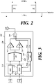
- For example, as shown in
FIG. 2 , different band signals FA1 and FA2 to be processed by one DPD may be non-contiguous and the bandwidth between FA1 and FA2 may be 400 MHz. In this case, the DPD or the like needs to perform signal processing on a bandwidth of at least three times (e.g., 1.2 GHz). However, signal processing for such a wide bandwidth (i.e., wideband) may exceed the capability of the currently commercialized DPD or the like. - An object of an embodiment of the present disclosure is to provide a transmitter capable of acceptably processing a non-contiguous wideband signal by processing a multi-band signal through different paths for the different bands of the multi-band signal.
- Various aspects of the present disclosure are directed to providing a multi-band transmitter for transmitting a multi-band signal. The multi-band transmitter comprises a pre-distortion unit including a first digital pre-distorter (DPD) for pre-distorting a first band signal and a second DPD for pre-distorting a second-band signal non-contiguous to the first band signal. The multi-band transmitter further comprises a conversion unit for converting the pre-distorted first band signal and the pre-distorted second band signal into analog signals, and an amplification unit including a first power amplifier (PA) for amplifying the analog-converted first band signal and a second PA for amplifying the analog-converted second band signal. The multi-band transmitter further comprises a feedback unit for converting the amplified first band signal into a digital signal and feeding the digital signal back to the first DPD and converting the amplified second band signal into a digital signal and feeding the digital signal to the second DPD. The pre-distortion unit performs pre-distortion using the fed-back first band signal and the fed-back second band signal.
- As described above, the present disclosure can process a wideband multi-band signal accurately and efficiently. In addition, the present disclosure can provide a transmission function more suited to diversification of a mobile communication system by accurately and efficiently processing the wideband multi-band signal. Furthermore, the present disclosure can reduce the number of internal components of the transmitter, thereby reducing the size of the transmitter and improving the ease or efficiency of manufacturing.
-
-
FIG. 1 is a block diagram showing an example of a conventional multi-band transmitter. -
FIG. 2 is a diagram illustrating a wideband multi-band signal. -
FIG. 3 is an exemplary block diagram of a transmitter capable of implementing techniques of the present disclosure. -
FIG. 4 is a diagram for describing a wideband multi-band signal processed by a multi-band transmitter of the present disclosure. -
FIG. 5 is a block diagram illustrating another example of a transmitter capable of implementing the techniques of the present disclosure. -
FIG. 6 is a block diagram illustrating another example of a transmitter capable of implementing the techniques of the present disclosure. - Hereinafter, various exemplary embodiments of the present disclosure will be described in detail with reference to the accompanying drawings. The same reference numerals are used throughout the drawings to designate the same or similar components. Furthermore, when it is determined that the detailed description of the known art may obscure the gist of the present disclosure, the detailed description will be omitted.
- It will be understood that, although the terms first , second , etc. may be used herein to describe various elements, these elements should not be limited by these terms. These terms are only used to distinguish one element from another element. It will be further understood that the terms comprise , include , have , etc. when used in the exemplary embodiment, specify the presence of stated features, integers, steps, operations, elements, components, and/or combinations thereof but do not preclude the presence or addition of one or more other features, integers, steps, operations, elements, components, and/or combinations thereof. Furthermore, the terms unit , module , etc. described in the exemplary embodiment means a unit that processes at least one function or operation, which may be implemented as hardware or software or a combination of hardware and software.
- The present disclosure discloses a multi-band transmitter, which is a device capable of accurately and efficiently processing a wideband signal.
-
FIG. 3 is an exemplary block diagram of a multi-band transmitter capable of implementing techniques of the present disclosure. As shown inFIG. 3 , themulti-band transmitter 300 may include apre-distortion unit 310, aconversion unit 320, anamplifier 330, and afeedback unit 350. In addition, themulti-band transmitter 300 may further include anisolator 340 or further include a frequency converter (up-converter and down-converter (not shown)) in addition thereto. - Different band signals may be input to the
pre-distortion unit 310. The different band signals may be two or more band signals. In the present specification, it is assumed that the different band signals processed through thetransmitter 300 includes a first band signal FA1 and a second band signal FA2, and FA1 and FA2 may be non-contiguous wideband signals. - The
pre-distortion unit 310 corresponds to a component for pre-distorting the different band signals of the multi-band signal. - The
pre-distortion unit 310 may include a first DPD (denoted as DPD1 312) and a second DPD (denoted as DPD2 314). DPD1 312 may pre-distort FA1 and DPD2 314 may pre-distort FA2. DPD1 312 and DPD2 314 may pre-distort FA1 and FA2 based on signals fed-back from thefeedback unit 350. - As described above, the
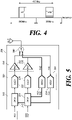
pre-distortion unit 310 may include the component DPD1 for pre-distorting FA1 and the component DPD2 for pre-distorting FA2 as separate components. That is, thepre-distortion unit 310 may process the different band signals of the multi-band signal through different paths (or different components). Accordingly, FA1 and FA2 may be pre-distorted through different components. - For example, as shown in
FIG. 4 , when the bandwidth between FA1 and FA2 is 400 MHz (wideband), the band for FA1 (300 MHz on the left) and the band for FA2 (300 MHz on the right) may be separately pre-distorted. Each band corresponds to a bandwidth (300 MHz) that can be processed by one DPD. Accordingly, the present disclosure can solve the problem of the prior art in that a wideband multi-band signal cannot be acceptably processed. - The pre-distorted band signals are input to the
converter 320. Theconversion unit 320 may convert the pre-distorted FA1 into an analog signal and convert the pre-distorted FA2 into an analog signal. - Specific embodiments of the
conversion unit 320 will be described later. - The analog-converted FA1 and the analog-converted FA2 are input to the
amplifier 330. In this process, the frequencies of analog-converted FA1 and analog-converted FA2 may be up-converted to RFs through a frequency converter (not shown). - The
amplifier 330 corresponds to a component for amplifying the power of the different band signals. - The amplifies 330 may include a first PA (denoted as PA1 332) and a second PA (denoted as PA2 334).
PA1 332 may amplify analog-converted (and frequency up-converted) FA1, andPA2 334 may amplify analog-converted (and frequency up-converted) FA2. - In this manner, the
amplifier 330 may include the component PA1 for amplifying FA1 and the component PA2 for amplifying FA2 as separate components. That is, theamplifier 330 may process the different band signals through different paths (or different components). Accordingly, FA1 and FA2 can be amplified through different components. Therefore, the present disclosure can process the wideband multi-band signal more accurately and efficiently. - The amplified band signals are input to the
isolator 340. Theisolator 340 corresponds to a component for transmitting the amplified band signals only in the direction of an antenna ANT. That is, theisolator 340 may prevent a reverse signal from being input to themulti-band transmitter 300. Theisolator 340 may be implemented using a circulator. - The amplified band signals are input to the
feedback unit 350. In this stage, the frequencies of the amplified multi-band signals may be down-converted to a baseband through a frequency converter (not shown). - The
feedback unit 350 may convert the amplified (and frequency down-converted) FA1 into a digital signal and convert the amplified (and frequency down-converted) FA2 into a digital signal. Further, thefeedback unit 350 may feed back the digital-converted FA1 to DPD1 312 and feed back the digital-converted FA2 toDPD2 314. Thepre-distortion unit 310 may pre-distort the input FA1 and FA2 based on the fed-back FA1 and FA2. - Embodiment 1 uses a method of respectively processing different band signals through different paths by at least one of the
conversion unit 320 and thefeedback unit 350. Embodiment 1 can be divided into embodiment (1-1) for a specific design of theconversion unit 320 and embodiment (1-2) for a specific design of thefeedback unit 350. -
FIG. 5 is a block diagram illustrating another example of a transmitter capable of implementing the techniques of the present disclosure. As shown inFIG. 5 , theconversion unit 320 may include first DAC (denoted as DAC1 522) and a second DAC (denoted as DAC2 524). -
DPD1 312 may transmit the pre-distorted FA1 toDAC1 522, andDPD2 314 may transmit the pre-distorted FA2 toDAC2 524. -
DAC1 522 may convert FA1 pre-distorted inDPD1 312 into an analog signal, andDAC2 524 may convert FA2 pre-distorted inDPD2 314 into an analog signal. That is, FA1 and FA2 may be converted to analog signals through different paths. - In this manner, the
conversion unit 320 may include the component DAC1 for converting FA1 and the component DAC2 for converting FA2 as separate components. That is, theconversion unit 320 may process the different band signals of the multi-band signal through different paths (or different components). Accordingly, FA1 and FA2 may be converted through different components. Therefore, the present disclosure can process a wideband multi-band signal more accurately and efficiently. -
DAC1 522 may transmit the analog-converted FA1 toPA1 332, andDAC2 524 may transmit the analog-converted FA2 toPA2 334. - As shown in
FIG. 5 , thefeedback unit 350 may include a first ADC (denoted as ADC1 554) and a second ADC (denoted as ADC2 552). - FA1 amplified by
PA1 332 may be input toADC1 554, and FA2 amplified byPA2 334 may be input toADC2 552. In this stage, the frequency of amplified FA1 may be down-converted to a baseband and the frequency of amplified FA2 may also be down-converted to a baseband through a frequency converter (not shown). -
ADC1 554 may convert the amplified (and frequency down-converted) FA1 into a digital signal, andADC2 552 may convert the amplified (and frequency down-converted) FA2 into a digital signal. Further,ADC1 554 may feed back the digital-converted FA1 toDPD1 312, andADC2 552 may feed back the digital-converted FA2 toDPD2 314. - In this manner, the
feedback unit 350 may include the component (ADC1) for converting and feeding back FA1 and the component (ADC2) for converting and feeding back FA2 as separate components. That is, thefeedback unit 350 may process the different band signals of the multi-band signal through different paths (or different components). Accordingly, FA1 and FA2 can be converted and fed-back through different components. Therefore, the present disclosure can process a wideband multi-band signal more accurately and efficiently. - Embodiment 2 uses a method of reducing the number of internal components of the
conversion unit 320 and thefeedback unit 350. - The use of a high-performance DAC and ADC (or a wideband DAC and a wideband ADC) suitable for processing the wideband multi-band signal may be contemplated. In view of this, the present disclosure proposes the
multi-band transmitter 300 that includes theconversion unit 320 for converting the wideband multi-band signal into an analog signal through a single path and thefeedback unit 350 for converting the wideband multi-band signal into a digital signal through a single path. When the wideband multi-band signal is processed through a single path, the size of themulti-band transmitter 300 can be reduced and ease or efficiency of manufacturing can be improved. - Embodiment 2 can be divided into embodiment (2-1) for a specific design of the
conversion unit 320 and embodiment (2-2) for a specific design of thefeedback unit 350. -
FIG. 6 is a block diagram illustrating another example of a transmitter capable of implementing the techniques of the present disclosure. As shown inFIG. 6 , theconversion unit 320 may include a mixer (includingcomponents DAC 624, and a filter unit (includingcomponents 626 and 628). - The mixer may combine or synthesize FA1 pre-distorted by
DPD1 312 and FA2 pre-distorted byDPD2 314 to output a combined signal. That is, the mixer may perform a function of combining FA1 and FA2 to form a single path for analog conversion. - The mixer may include a first up-converter (denoted as NCO1 621), a second up-converter (denoted as NCO2 622), and an
adder 623.NCO1 621 may up-convert the frequency of the pre-distorted FA1, andNCO2 622 may up-convert the frequency of the pre-distorted FA2. Theadder 623 may add the up-converted FA1 to the up-converted FA2 to output a combined signal. - The
DAC 624 may convert the combined signal output from theadder 623 into an analog signal. That is, theconversion unit 320 can convert the multi-band signal (including FA1 and FA2) using onewideband DAC 624 capable of processing the wideband multi-band signal. - The filter unit may filter the analog-converted signals FA1 and FA2 from the analog-converted combined signal. The filter unit may include a
first filter 626 and asecond filter 628. Thefirst filter 626 may filter or separate the analog-converted signal FA1 from the analog-converted combined signal, and thesecond filter 626 may filter or separate the analog-converted signal FA2 from the analog-converted combined signal. - The filtered signal FA1 may be input to
PA1 332 and amplified thereby, and the filtered signal FA2 may be input toPA2 334 and amplified thereby. - As shown in
FIG. 6 , thefeedback unit 350 may include a digital conversion unit (including 652 and 654), a third down-converter (denoted as NCO3 658), and a fourth down-converter (denoted as NCO4 656). - The digital conversion unit may convert FA1 amplified by
PA1 332 into a digital signal for a first period of time and convert FA2 amplified byPA2 334 into a digital signal for a second period of time. That is, the digital conversion unit may convert any one of the amplified FA1 and the amplified FA2 into a digital signal at any instant of time. Accordingly, the digital conversion unit can perform a function of forming a single path for digital conversion of a multi-band signal. - The digital conversion unit may include a switch (S/W) 652 and an
ADC 654. Theswitch 652 may select one of the amplified FA1 and the amplified FA2. TheADC 654 may convert the signal (i.e., either amplified FA1 or amplified FA2) selected by theswitch 652 into a digital signal. -
NCO3 658 may down-convert the frequency of the converted digital signal FA1 and feed the same back toDPD1 312.NCO4 656 may down-convert the frequency of the converted digital signal FA2 and feed the same back toDPD2 314. - Although embodiments have been described for illustrative purposes, those having ordinary skill in the art should appreciate that and various modifications and changes are possible, without departing from the idea and scope of the embodiments. Embodiments have been described for the sake of brevity and clarity. Accordingly, one of ordinary skill should understand that the scope of the embodiments is not limited by the embodiments explicitly described above but is inclusive of the claims and equivalents thereto.
- This application claims priority to
Korean Patent Application No. 10-2020-0023103, filed on February 25, 2020
Claims (7)
- A multi-band transmitter for transmitting a multi-band signal, comprising:a pre-distortion unit including a first digital pre-distorter (DPD) for pre-distorting a first band signal and a second DPD for pre-distorting a second-band signal non-contiguous to the first band signal;a conversion unit for converting the pre-distorted first band signal and the pre-distorted second band signal into analog signals;an amplification unit including a first power amplifier (PA) for amplifying the analog-converted first band signal and a second PA for amplifying the analog-converted second band signal; anda feedback unit for converting the amplified first band signal into a digital signal and feeding the digital signal back to the first DPD and converting the amplified second band signal into a digital signal and feeding the digital signal to the second DPD,wherein the pre-distortion unit performs pre-distortion using the fed-back first band signal and the fed-back second band signal.
- The multi-band transmitter of claim 1, wherein the conversion unit includes:a first digital-to-analog converter (DAC) for converting the pre-distorted first band signal into an analog signal; anda second DAC for converting the pre-distorted second-band signal into an analog signal.
- The multi-band transmitter of claim 1, wherein the conversion unit includes:a mixer for combining the pre-distorted first band signal and the pre-distorted second band signal and outputting a combined signal;a digital-to-analog converter (DAC) for converting the combined signal into an analog signal; anda filter unit for filtering the analog-converted first band signal and the analog-converted second band signal from the analog-converted combined signal.
- The multi-band transmitter of claim 3, wherein the mixer includes:a first up-converter for up-converting a frequency of the pre-distorted first band signal;a second up-converter for up-converting a frequency of the pre-distorted second band signal; andan adder for combining the up-converted first band signal and the up-converted second band signal to output the combined signal.
- The multi-band transmitter of claim 1, wherein the feedback unit includes:a first analog-to-digital converter (ADC) for converting the amplified first band signal into a digital signal and feeding the digital signal back to the first DPD; anda second ADC for converting the amplified second band signal into a digital signal and feeding the digital signal back to the second DPD.
- The multi-band transmitter of claim 1, wherein the feedback unit includes:a digital conversion unit for converting the amplified first band signal into a digital signal or converting the amplified second band signal into a digital signal;a third down-converter for down-converting a frequency of the converted digital first band signal and feeding back the down-converted digital first band signal to the first DPD;
anda fourth down-converter for down-converting a frequency of the converted digital second band signal and feeding back the down-converted digital second band signal to the second DPD. - The multi-band transmitter of claim 6, wherein the digital conversion unit includes:a switch for selecting one of the amplified first band signal and the amplified second band signal; andan ADC for converting the signal selected by the switch into a digital signal.
Applications Claiming Priority (2)
| Application Number | Priority Date | Filing Date | Title |
|---|---|---|---|
| KR1020200023103A KR20210108196A (en) | 2020-02-25 | 2020-02-25 | Multi band transmitter |
| PCT/KR2021/001771 WO2021172796A1 (en) | 2020-02-25 | 2021-02-10 | Multi-band transmitter |
Publications (2)
| Publication Number | Publication Date |
|---|---|
| EP4113850A1 true EP4113850A1 (en) | 2023-01-04 |
| EP4113850A4 EP4113850A4 (en) | 2024-03-06 |
Family
ID=77490307
Family Applications (1)
| Application Number | Title | Priority Date | Filing Date |
|---|---|---|---|
| EP21761276.1A Pending EP4113850A4 (en) | 2020-02-25 | 2021-02-10 | MULTI-BAND TRANSMITTER |
Country Status (6)
| Country | Link |
|---|---|
| US (1) | US12323176B2 (en) |
| EP (1) | EP4113850A4 (en) |
| JP (1) | JP7446452B2 (en) |
| KR (1) | KR20210108196A (en) |
| CN (1) | CN115104261A (en) |
| WO (1) | WO2021172796A1 (en) |
Families Citing this family (2)
| Publication number | Priority date | Publication date | Assignee | Title |
|---|---|---|---|---|
| EP3993262A1 (en) * | 2020-11-02 | 2022-05-04 | Nokia Solutions and Networks Oy | A radio apparatus |
| KR102881542B1 (en) * | 2023-12-05 | 2025-11-05 | (주)에프알텍 | roadband division processing device and method for communication relay system |
Family Cites Families (31)
| Publication number | Priority date | Publication date | Assignee | Title |
|---|---|---|---|---|
| US7183847B2 (en) * | 2004-01-28 | 2007-02-27 | Ntt Docomo, Inc. | Multi-band look-up table type predistorter |
| US7577211B2 (en) * | 2004-03-01 | 2009-08-18 | Powerwave Technologies, Inc. | Digital predistortion system and method for linearizing an RF power amplifier with nonlinear gain characteristics and memory effects |
| KR100837243B1 (en) * | 2006-02-27 | 2008-06-11 | 인천대학교 산학협력단 | Predistortion linearization equipment of frequency multiplier and dual mode transmitter using the predistortion linearization equipment |
| US7783263B2 (en) * | 2006-12-14 | 2010-08-24 | Texas Instruments Incorporated | Simplified digital predistortion in a time-domain duplexed transceiver |
| CN101741317B (en) * | 2009-11-26 | 2011-12-28 | 北京北方烽火科技有限公司 | Digital predistortion linear broadband radio-frequency power amplifier device |
| US8351877B2 (en) * | 2010-12-21 | 2013-01-08 | Dali Systems Co. Ltfd. | Multi-band wideband power amplifier digital predistorition system and method |
| US8542768B2 (en) * | 2009-12-21 | 2013-09-24 | Dali Systems Co. Ltd. | High efficiency, remotely reconfigurable remote radio head unit system and method for wireless communications |
| US8138014B2 (en) * | 2010-01-29 | 2012-03-20 | Stats Chippac, Ltd. | Method of forming thin profile WLCSP with vertical interconnect over package footprint |
| JP5995858B2 (en) * | 2010-11-18 | 2016-09-21 | テレフオンアクチーボラゲット エルエム エリクソン(パブル) | Method and frequency agile predistortion transmitter using programmable digital up / down conversion |
| US8576943B2 (en) * | 2011-09-09 | 2013-11-05 | Telefonaktiebolaget L M Ericsson (Publ) | Linearization for a single power amplifier in a multi-band transmitter |
| US8380144B1 (en) * | 2011-09-30 | 2013-02-19 | Telefonaktiebolaget L M Ericsson (Publ) | Systems and methods for digital predistortion in a dual band transmitter |
| US8817859B2 (en) * | 2011-10-14 | 2014-08-26 | Fadhel Ghannouchi | Digital multi-band predistortion linearizer with nonlinear subsampling algorithm in the feedback loop |
| JP5804092B2 (en) | 2012-02-09 | 2015-11-04 | 日本電気株式会社 | Transmitter and transmission method |
| US8634494B2 (en) * | 2012-03-19 | 2014-01-21 | Telefonaktiebolaget L M Ericsson (Publ) | Bandpass sampling schemes for observation receiver for use in PA DPD system for concurrent multi-band signals |
| US8923787B2 (en) * | 2012-07-05 | 2014-12-30 | Pierre-André LAPORTE | Low sampling rate adaptation scheme for dual-band linearization |
| WO2017167354A1 (en) * | 2016-03-29 | 2017-10-05 | Intel Corporation | Digital predistortion for dual-band power amplifiers |
| US9923595B2 (en) * | 2013-04-17 | 2018-03-20 | Intel Corporation | Digital predistortion for dual-band power amplifiers |
| US8948301B2 (en) * | 2013-05-24 | 2015-02-03 | Telefonaktiebolaget L M Ericsson (Publ) | Multi-band radio-frequency digital predistortion |
| US9608676B2 (en) * | 2013-07-12 | 2017-03-28 | Analog Devices Global | Digital pre-distortion systems in transmitters |
| WO2015165087A1 (en) * | 2014-04-30 | 2015-11-05 | 华为技术有限公司 | Pre-distortion system and method |
| US9306506B1 (en) * | 2014-11-24 | 2016-04-05 | Analog Devices Global | Apparatus and methods for dual loop power amplifier digital pre-distortion systems |
| WO2016151518A1 (en) * | 2015-03-26 | 2016-09-29 | Telefonaktiebolaget Lm Ericsson (Publ) | Method and apparatus for multiband predistortion using time-shared adaptation loop |
| CN104901638B (en) * | 2015-06-03 | 2018-01-09 | 京信通信技术(广州)有限公司 | Multichannel digital predistortion DPD power amplification systems |
| US9749161B1 (en) * | 2016-02-23 | 2017-08-29 | Nxp Usa, Inc. | Fixed-point conjugate gradient digital pre-distortion (DPD) adaptation |
| CN106685868B (en) * | 2017-01-03 | 2020-09-08 | 电子科技大学 | Adjacent multiband digital predistortion system and method |
| EP4472083A3 (en) * | 2017-08-10 | 2025-02-26 | Outdoor Wireless Networks LLC | Methods and apparatuses for digital pre-distortion |
| CN109428610B (en) * | 2017-08-29 | 2020-10-16 | 华为技术有限公司 | Feedback circuit unit, ROF wireless transmitter and method for eliminating nonlinear distortion |
| JP2019201361A (en) * | 2018-05-17 | 2019-11-21 | 富士通株式会社 | Distortion compensation apparatus and distortion compensation method |
| KR102255390B1 (en) | 2018-08-24 | 2021-05-21 | 주식회사 엘지화학 | Liquid crystal alignment film, method of preparing liquid crystal alignment film, and liquid crystal display device using the same |
| KR102622024B1 (en) * | 2019-01-15 | 2024-01-08 | 삼성전자 주식회사 | Electronic device for reducing noise in a frequency band of rx signal and method for the same |
| EP3872987B1 (en) * | 2020-02-04 | 2025-11-26 | Nokia Solutions and Networks Oy | Dual-band digital pre-distortion |
-
2020
- 2020-02-25 KR KR1020200023103A patent/KR20210108196A/en not_active Ceased
-
2021
- 2021-02-10 JP JP2022549634A patent/JP7446452B2/en active Active
- 2021-02-10 WO PCT/KR2021/001771 patent/WO2021172796A1/en not_active Ceased
- 2021-02-10 CN CN202180014605.4A patent/CN115104261A/en active Pending
- 2021-02-10 EP EP21761276.1A patent/EP4113850A4/en active Pending
-
2022
- 2022-08-24 US US17/895,034 patent/US12323176B2/en active Active
Also Published As
| Publication number | Publication date |
|---|---|
| KR20210108196A (en) | 2021-09-02 |
| JP2023515037A (en) | 2023-04-12 |
| US12323176B2 (en) | 2025-06-03 |
| WO2021172796A1 (en) | 2021-09-02 |
| US20220416826A1 (en) | 2022-12-29 |
| JP7446452B2 (en) | 2024-03-08 |
| EP4113850A4 (en) | 2024-03-06 |
| CN115104261A (en) | 2022-09-23 |
Similar Documents
| Publication | Publication Date | Title |
|---|---|---|
| CA2821892C (en) | Systems and methods for digital predistortion in a dual band transmitter | |
| US8750410B2 (en) | Multi-band power amplifier digital predistortion system and method | |
| US20130243121A1 (en) | Bandpass sampling schemes for observation receiver for use in pa dpd system for concurrent multi-band signals | |
| EP2169837A1 (en) | Technique for suppressing noise in a transmitter device | |
| US8238838B2 (en) | Calibration of transmit signals in FDD-transceivers | |
| CN101534133A (en) | Wireless transceiver | |
| US12323176B2 (en) | Multiband transmitter efficiently implementing pre-distortion | |
| JP6705918B2 (en) | Wireless device and wireless communication method | |
| EP3414843B1 (en) | Radio frequency (rf) transmitter and noise mitigation device | |
| CN101777932A (en) | Antenna element multiplexing method and device and antenna assembly | |
| CN106464281B (en) | Reconfigurable transmitter and receiver and reconfiguration method thereof | |
| US6784731B2 (en) | System and method for reducing amplifier distortion using distortion feedback | |
| WO2017143926A1 (en) | Signal processing arrangement for a transmitter | |
| US8126421B2 (en) | Radio receiver | |
| CN100362747C (en) | Circuit to suppress LO leakage | |
| KR20090097295A (en) | TDD wireless communication system and method using digital predistortion method | |
| EP2161841B1 (en) | Predistortion of a radio frequency signal | |
| EP3776847A1 (en) | Baseband frequency selective magnitude and phase adjustment for wideband doherty power amplifier | |
| US7062231B2 (en) | Direct modulation transmitter utilizing signals squaring | |
| US20040198269A1 (en) | Linearization of amplified feedback distortion | |
| WO2022203554A1 (en) | Method and arrangements for supporting intermodulaton component suppression in a transmitter system with digital predistortion and feedforward linearization | |
| EP2663046A1 (en) | Apparatus and method for slew-rate limitation | |
| US20110306391A1 (en) | Transmitter architecture enabling efficient preamplification gain control and related method | |
| CN117941326B (en) | Frequency predistortion device, frequency predistortion method and transmitting system | |
| Katz et al. | Integrated linearizer/block upconverters |
Legal Events
| Date | Code | Title | Description |
|---|---|---|---|
| STAA | Information on the status of an ep patent application or granted ep patent |
Free format text: STATUS: THE INTERNATIONAL PUBLICATION HAS BEEN MADE |
|
| PUAI | Public reference made under article 153(3) epc to a published international application that has entered the european phase |
Free format text: ORIGINAL CODE: 0009012 |
|
| STAA | Information on the status of an ep patent application or granted ep patent |
Free format text: STATUS: REQUEST FOR EXAMINATION WAS MADE |
|
| 17P | Request for examination filed |
Effective date: 20220921 |
|
| AK | Designated contracting states |
Kind code of ref document: A1 Designated state(s): AL AT BE BG CH CY CZ DE DK EE ES FI FR GB GR HR HU IE IS IT LI LT LU LV MC MK MT NL NO PL PT RO RS SE SI SK SM TR |
|
| DAV | Request for validation of the european patent (deleted) | ||
| DAX | Request for extension of the european patent (deleted) | ||
| A4 | Supplementary search report drawn up and despatched |
Effective date: 20240202 |
|
| RIC1 | Information provided on ipc code assigned before grant |
Ipc: H04B 1/04 20060101ALI20240129BHEP Ipc: H04B 1/00 20060101AFI20240129BHEP |
|
| STAA | Information on the status of an ep patent application or granted ep patent |
Free format text: STATUS: EXAMINATION IS IN PROGRESS |
|
| 17Q | First examination report despatched |
Effective date: 20251113 |
|
| GRAP | Despatch of communication of intention to grant a patent |
Free format text: ORIGINAL CODE: EPIDOSNIGR1 |
|
| STAA | Information on the status of an ep patent application or granted ep patent |
Free format text: STATUS: GRANT OF PATENT IS INTENDED |