EP4113759A1 - Phase difference measurement device, beam output device, and phase difference measurement method - Google Patents
Phase difference measurement device, beam output device, and phase difference measurement method Download PDFInfo
- Publication number
- EP4113759A1 EP4113759A1 EP21781262.7A EP21781262A EP4113759A1 EP 4113759 A1 EP4113759 A1 EP 4113759A1 EP 21781262 A EP21781262 A EP 21781262A EP 4113759 A1 EP4113759 A1 EP 4113759A1
- Authority
- EP
- European Patent Office
- Prior art keywords
- laser beam
- phase
- detection
- intensity
- laser
- Prior art date
- Legal status (The legal status is an assumption and is not a legal conclusion. Google has not performed a legal analysis and makes no representation as to the accuracy of the status listed.)
- Pending
Links
Images







Classifications
-
- G—PHYSICS
- G01—MEASURING; TESTING
- G01J—MEASUREMENT OF INTENSITY, VELOCITY, SPECTRAL CONTENT, POLARISATION, PHASE OR PULSE CHARACTERISTICS OF INFRARED, VISIBLE OR ULTRAVIOLET LIGHT; COLORIMETRY; RADIATION PYROMETRY
- G01J9/00—Measuring optical phase difference; Determining degree of coherence; Measuring optical wavelength
- G01J9/02—Measuring optical phase difference; Determining degree of coherence; Measuring optical wavelength by interferometric methods
-
- G—PHYSICS
- G02—OPTICS
- G02B—OPTICAL ELEMENTS, SYSTEMS OR APPARATUS
- G02B5/00—Optical elements other than lenses
- G02B5/30—Polarising elements
- G02B5/3083—Birefringent or phase retarding elements
-
- G—PHYSICS
- G02—OPTICS
- G02B—OPTICAL ELEMENTS, SYSTEMS OR APPARATUS
- G02B5/00—Optical elements other than lenses
- G02B5/32—Holograms used as optical elements
-
- H—ELECTRICITY
- H01—ELECTRIC ELEMENTS
- H01S—DEVICES USING THE PROCESS OF LIGHT AMPLIFICATION BY STIMULATED EMISSION OF RADIATION [LASER] TO AMPLIFY OR GENERATE LIGHT; DEVICES USING STIMULATED EMISSION OF ELECTROMAGNETIC RADIATION IN WAVE RANGES OTHER THAN OPTICAL
- H01S3/00—Lasers, i.e. devices using stimulated emission of electromagnetic radiation in the infrared, visible or ultraviolet wave range
- H01S3/10—Controlling the intensity, frequency, phase, polarisation or direction of the emitted radiation, e.g. switching, gating, modulating or demodulating
- H01S3/13—Stabilisation of laser output parameters, e.g. frequency or amplitude
- H01S3/1307—Stabilisation of the phase
-
- H—ELECTRICITY
- H01—ELECTRIC ELEMENTS
- H01S—DEVICES USING THE PROCESS OF LIGHT AMPLIFICATION BY STIMULATED EMISSION OF RADIATION [LASER] TO AMPLIFY OR GENERATE LIGHT; DEVICES USING STIMULATED EMISSION OF ELECTROMAGNETIC RADIATION IN WAVE RANGES OTHER THAN OPTICAL
- H01S3/00—Lasers, i.e. devices using stimulated emission of electromagnetic radiation in the infrared, visible or ultraviolet wave range
- H01S3/23—Arrangements of two or more lasers not provided for in groups H01S3/02 - H01S3/22, e.g. tandem arrangements of separate active media
- H01S3/2383—Parallel arrangements
-
- G—PHYSICS
- G01—MEASURING; TESTING
- G01J—MEASUREMENT OF INTENSITY, VELOCITY, SPECTRAL CONTENT, POLARISATION, PHASE OR PULSE CHARACTERISTICS OF INFRARED, VISIBLE OR ULTRAVIOLET LIGHT; COLORIMETRY; RADIATION PYROMETRY
- G01J9/00—Measuring optical phase difference; Determining degree of coherence; Measuring optical wavelength
- G01J9/02—Measuring optical phase difference; Determining degree of coherence; Measuring optical wavelength by interferometric methods
- G01J2009/0261—Measuring optical phase difference; Determining degree of coherence; Measuring optical wavelength by interferometric methods polarised
-
- G—PHYSICS
- G01—MEASURING; TESTING
- G01J—MEASUREMENT OF INTENSITY, VELOCITY, SPECTRAL CONTENT, POLARISATION, PHASE OR PULSE CHARACTERISTICS OF INFRARED, VISIBLE OR ULTRAVIOLET LIGHT; COLORIMETRY; RADIATION PYROMETRY
- G01J9/00—Measuring optical phase difference; Determining degree of coherence; Measuring optical wavelength
- G01J9/02—Measuring optical phase difference; Determining degree of coherence; Measuring optical wavelength by interferometric methods
- G01J2009/028—Types
- G01J2009/0288—Machzehnder
-
- H—ELECTRICITY
- H01—ELECTRIC ELEMENTS
- H01S—DEVICES USING THE PROCESS OF LIGHT AMPLIFICATION BY STIMULATED EMISSION OF RADIATION [LASER] TO AMPLIFY OR GENERATE LIGHT; DEVICES USING STIMULATED EMISSION OF ELECTROMAGNETIC RADIATION IN WAVE RANGES OTHER THAN OPTICAL
- H01S3/00—Lasers, i.e. devices using stimulated emission of electromagnetic radiation in the infrared, visible or ultraviolet wave range
- H01S3/10—Controlling the intensity, frequency, phase, polarisation or direction of the emitted radiation, e.g. switching, gating, modulating or demodulating
- H01S3/10061—Polarization control
Definitions
- the present invention relates to a phase difference measuring device, a beam output apparatus and a phase difference measuring method, and can be suitably used as a phase difference measuring device, a beam output apparatus and a phase difference measuring method for a laser beam, for example.
- High-quality and high-power laser light is required in fields such as laser processing, scientific research, nuclear fusion, space debris removal, and security.
- due to factors such as heat generation, optical damage, and non-linear optical effects there is a limit to an output that can be achieved as a single laser beam. Therefore, the technology for combining a plurality of laser beams is being studied to increase the output power.
- a device, a process, or the like for temporal modulation and/or demodulation (frequency shift, phase modulation, or the like) of each laser beam is required.
- Patent Literature 1 US 2009/0134310 A1 discloses a laser system that combines a plurality of laser beams.
- a frequency shift is applied to each laser beam in order to calculate a phase of each laser beam.
- Patent Literature 2 Japanese Patent Publication No. 2014-216418 discloses a phase-locked laser device that combines a plurality of laser beams. In this phase-locked laser device, a frequency shift and a phase modulation are applied to each laser beam in order to calculate a phase of each laser beam.
- Patent Literature 3 Japanese Patent No. 6071202 discloses a multi-beam coupling device that couples a plurality of beams.
- a spatial interference pattern is used in order to control a phase of each laser beam. Since a phase is controlled based on a one-dimensional interference pattern, phase measurement is necessary at two or more positions for each beam.
- Non-Patent Literature 1 K. Sueda, G. Miyaji, N. Miyanaga and M. Nakatsuka, "Laguerre-Gaussian beam generated with a multilevel spiral phase plate for high intensity laser pulses", OPTICS EXPRESS, Optical Society of America, July 26, 2004, pp. 3548-3553 . discloses a phase distribution of a 16-step spiral phase plate, a prototype example, an interference pattern generated by a beam with 16-step spiral phase plate and a reference beam.
- Non-Patent Literature 1 K. Sueda, G. Miyaji, N. Miyanaga and M. Nakatsuka, "Laguerre-Gaussian beam generated with a multilevel spiral phase plate for high intensity laser pulses", OPTICS EXPRESS, Optical Society of America, July 26, 2004, pp. 3548-3553 .
- Phase difference between laser beams will be detected or measured in order to generate a high-power and high-quality laser beam.
- Other objectives and new features will be clarified by disclosures of the present description and attached drawings.
- a phase difference measuring device is provided with a phase conversion device and a detection device.
- the phase conversion device converts a first laser beam that passes therethrough so that the first laser beam includes a phase distribution of one cycle in an azimuth direction in a cross section of the first laser beam that has passed therethrough included in an arbitrary virtual plane perpendicular to an optical axis of the first laser beam.
- the detection device detects an azimuth angle of an intensity centroid of an interference pattern and detects an inter-beam phase difference of a second laser beam with respect to the first laser beam based on the azimuth angle.
- the interference pattern is generated by a shaped detection beam obtained by cutting out a part of a cross section of a detection beam into a shape of a circle with a point, where the cross section of the detection beam and an optical axis of the phase conversion device intersect, as a center thereof.
- the cross section of the detection beam is perpendicular to an optical axis of the detection beam.
- the detection beam is obtained by combining a first partial intensity laser beam and a second partial intensity laser beam on a same optical path.
- the first partial intensity laser beam has at least a part of an intensity component of the first laser beam that has passed through the phase conversion device.
- the second partial intensity laser beam has at least a part of an intensity component of a second laser beam derived from a laser beam as seed light from which the first laser beam derives.
- a beam output apparatus is provided with a first beam splitter, a phase conversion device, a detection device, and a phase controller.
- the first beam splitter splits a laser beam that is to be seed light into a first laser beam and a second laser beam.
- the phase conversion device converts the first laser beam that passes therethrough, so that the first laser beam includes a phase distribution of one cycle in an azimuth direction in a cross section of the first laser beam that has passed therethrough included in an arbitrary virtual plane perpendicular to an optical axis of the first laser beam.
- the detection device detects an azimuth angle of an intensity centroid of an interference pattern and detects an inter-beam phase difference of the second laser beam with respect to the first laser beam based on the azimuth angle.
- the interference pattern is generated by a shaped detection beam obtained by cutting out a part of a cross section of the detection beam into a shape of a circle with a point, where the cross section of the detection beam and an optical axis of the phase conversion device intersect, as a center thereof.
- the cross section of the detection beam is perpendicular to an optical axis of a detection beam.
- the detection beam is obtained by combining a first partial intensity laser beam and a second partial intensity laser beam on a same optical path.
- the first partial intensity laser beam has at least a part of an intensity component of the first laser beam that has passed through the phase conversion device.
- the second partial intensity laser beam has at least a part of an intensity component of the second laser beam.
- the phase controller controls a phase of the second laser beam based on the phase difference.
- a phase difference measuring method includes: converting a first laser beam that passes through a phase conversion device, so that the first laser beam includes a phase distribution of one cycle in an azimuth direction in a cross section of the first laser beam that has passed therethrough included in an arbitrary virtual plane perpendicular to an optical axis of the first laser beam; detecting an azimuth angle of an intensity centroid of an interference pattern; and detecting an inter-beam phase difference of a second laser beam with respect to the first laser beam based on the azimuth angle.
- the interference pattern is generated by a shaped detection beam obtained by cutting out a part of a cross section of the detection beam into a shape of a circle with a point, where the cross section of the detection beam and an optical axis of the phase conversion device intersect, as a center thereof.
- the cross section of the detection beam is perpendicular to an optical axis of a detection beam.
- the detection beam is obtained by combining a first partial intensity laser beam and a second partial intensity laser beam on a same optical path.
- the first partial intensity laser beam has at least a part of an intensity component of the first laser beam that is converted.
- the second partial intensity laser beam has at least a part of an intensity component of the second laser beam derived from a laser beam as seed light from which the first laser beam derives.
- a high-power and high-quality laser beam can be generated.
- a laser light beam may be referred to as a laser beam or a beam.
- FIG. 1 is a diagram that shows a configuration example of a beam output apparatus 1 according to an embodiment.
- the beam output apparatus 1 in FIG. 1 is provided with a laser oscillator 2, a beam splitter 3, a reference beam generation section 4, a test beam generation section 5 and a phase difference measuring device 6.
- the reference beam generation section 4 is provided with a beam expander 44 and a reflector 45.
- the test beam generation section 5 is provided with a controller 51, a phase controller 53, a beam expander 54, an amplifier 55, and a reflector 57.
- the phase difference measuring device 6 is provided with a spiral phase plate 61, a beam splitter 62, and a detection device 60.
- the detection device 60 is provided with an aperture 63, a four-quadrant detector 64, and a processor 65.
- the laser oscillator 2 generates a laser beam L0 that is to be seed light.
- the beam splitter 3 is arranged downstream of the laser oscillator 2 and splits the generated laser beam L0 into a first laser beam and a second laser beam.
- the first laser beam and the second laser beam may be outputted to different directions.
- the reference beam generation section 4 is arranged downstream of the beam splitter 3 and incidents the first laser beam to output a reference beam L1. In other words, the reference beam generation section 4 is arranged at a position where the first laser beam is incident.
- the beam expander 44 may be arranged upstream to the reflector 45.
- the beam expander 44 enlarges a cross-sectional area of the first laser beam and outputs it.
- the reflector 45 reflects the first laser beam of which the cross-sectional area is enlarged to output as the reference beam L1. It should be noted that the order of enlarging the cross-sectional area and reflecting may be changed.
- the beam expander 44 may be arranged upstream to the reflector 45 and may be arranged downstream of the reflector 45.
- the test beam generation section 5 is arranged downstream of the beam splitter 3 and incidents the second laser beam to output a test beam L2. In other words, the test beam generation section 5 is arranged at a position where the second laser beam outputted from the beam splitter 3 is incident.
- the phase controller 53 incidents the second laser beam and shifts a phase thereof. At that time, the phase controller 53 performs a phase shift of the second laser beam based on a phase control signal CS that is electrically provided from the controller 51.
- the beam expander 54 receives the second laser beam of which the phase is shifted, enlarges a cross-sectional area thereof, and outputs it. In other words, the beam expander 54 is arranged downstream of the phase controller 53.
- the amplifier 55 receives the second laser beam of which the cross-sectional area is enlarged, amplifies an optical intensity thereof, and outputs it. In other words, the amplifier 55 is arranged downstream of the beam expander 54.
- the reflector 57 reflects the second laser beam of which the optical intensity is amplified and outputs it as the test beam L2.
- the reflector 57 is arranged downstream of the amplifier 55.
- the controller 51 is electrically provided with a detector signal DS from the processor 65 of the phase difference measuring device 6 that will be described later, and outputs the phase control signal CS based on the detector signal DS.
- the controller 51 may not be optically connected between other components of the test beam generation section 5. It should be noted that an optical arrangement of the components of the test beam generation section 5 may be arbitrarily changed within a technically consistent range.
- the beam splitter 62 has a low reflection coating on one side and an anti-reflection coating on the other side, and guides a test beam L22, that is a slight part of an intensity component (power) of the test beam L2 being reflected thereby, and a reference beam L12, that is a most part of an intensity component (power) of the reference beam L1 being transmitted therethrough, to the detection device 60, in parallel to each other.
- the phase difference measuring device 6 receives the reference beam L1 and the test beam L2 and outputs the detector signal DS that shows a result of measuring an inter-beam phase difference between those two beams L1 and L2.
- the phase difference measuring device 6 is arranged downstream of the reference beam generation section 4 and is arranged downstream of the test beam generation section 5 as well. It should be noted that, from the reference beam L1 and the test beam L2 that are inputted, the phase difference measuring device 6 outputs a most part of the test beam L2 and a slight part of the reference beam L1, that were not used for the phase difference measurement, as a combined beam L3. It should be noted that the combined beam L3 may be outputted to be combined to another beam, and this combining may be performed by another optical system that is not illustrated.
- the spiral phase plate 61 receives and passes the reference beam L1 and converts a phase distribution of the passing reference beam L1.
- the beam splitter 62 transmits, on one hand, a most part of the reference beam L1 of which the phase distribution is converted as the reference beam L12, and reflects a slight part as a residual reflected beam L11.
- the beam splitter 62 reflects, on the other hand, a slight part of the test beam L2 as the test beam L22 and outputs a most part of the test beam L2 as a transmitted beam L21.
- the test beam L22 and the reference beam L12 are outputted to the detection device 60 as a detection beam L4.
- the beam splitter 62 is arranged at a position where the reference beam L1 and the test beam L2 intersect. It should be noted that a transmittance and a reflectance of the beam splitter 62 are not limited to the above example.
- the aperture 63 receives the detection beam L4 and passes a part thereof.
- the four-quadrant detector 64 is provided with quadrant sensors that detect an optical intensity of the part of the detection beam L4 that has passed through the aperture 63 and generates optical intensity signals PS1 to PS4 that electrically represent an optical intensity distribution thereof.
- the four-quadrant detector 64 is a sensor device arranged downstream of the aperture 63.
- the processor 65 is electrically supplied with the optical intensity signals PS1 to PS4, calculates the phase difference based on them, and generates the detector signal DS that electrically represents the calculated phase difference.
- the processor 65 is electrically connected to downstream of the four-quadrant detector 64.
- the processor 65 may be provided with a computer provided with a microcomputer chip that performs predetermined processes or a Central Processing Unit (CPU) that executes predetermined programs, a storage device that stores the programs and various data, and various interfaces that perform inputs and outputs of data from or to outside. It should be noted that an analog microcomputer is more advantageous for increasing control speed.
- CPU Central Processing Unit
- the laser oscillator 2 generates the laser beam L0 that is to be the seed light.
- This laser beam L0 may be a continuous wave or a pulsed wave.
- the beam splitter 3 splits the laser beam L0 into a first laser beam and a second laser beam.
- the beam splitter 3 may be a half mirror that transmits a part of the laser beam L0 as the first laser beam and reflects another part of the laser beam L0 as the second laser beam.
- ratios of transmission and reflection do not need to be the same.
- the reference beam generation section 4 receives the first laser beam and generates the reference beam L1.
- the beam expander 44 enlarges the cross-sectional area of the first laser beam and outputs it as a parallel beam.
- the beam expander 44 may be provided with a combination of a plurality of lenses, for example.
- the reflector 45 reflects the first laser beam, of which the cross-sectional area is enlarged, to output as the reference beam L1. It should be noted that the order of the enlarging the cross-sectional area and the reflecting may be changed.
- the test beam generation section 5 receives the second laser beam and generates the test beam L2.
- the controller 51 generates the phase control signal CS based on the detector signal DS.
- the phase controller 53 controls the phase of the second laser beam based on the phase control signal CS.
- the phase controller 53 adjusts the phase of the second laser beam that passes through the phase controller 53 based on the phase control signal CS.
- the beam expander 54 enlarges the cross-sectional area of the second laser beam of which the phase is shifted and outputs it as a parallel beam.
- the amplifier 55 amplifies the second laser beam of which the cross-sectional area is enlarged.
- the reflector 57 reflects the amplified second laser beam and outputs it as the test beam L2 to the beam splitter 62. It should be noted that the order of shifting the phase, enlarging the cross-sectional area, amplifying, and reflecting of the second laser beam may be changed within a technically consistent range.
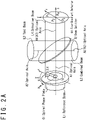
- FIG. 2A is a diagram for describing an operation principle of the phase difference measuring device 6 according to an embodiment.
- the spiral phase plate 61 converts the phase distribution of the reference beam L1 that passes therethrough.
- the spiral phase plate 61 converts an incident beam of which the phase is spatially uniform to a transmitted beam having a spatial phase distribution.
- the spiral phase plate 61 shown in FIG. 2A has a configuration in that a material is transparent and a thickness gradually increases in an azimuth direction with the optical axis A1 thereof as a center of rotation.
- the converted phase distribution of the reference beam L1 is configured to totally include a range of phase of one cycle, for example a range of phase from zero radian to 2 ⁇ radians, along the azimuth direction in an arbitrary cross-section perpendicular to the optical axis A1 of the reference beam L1.
- the spiral phase plate 61 may be configured so that, when going around in a predetermined direction along the azimuth angle in an arbitrary cross-section perpendicular to the optical axis A2 of the reference beam L1, a distribution density of an arbitrary phase included in a phase range of one cycle is uniform.
- the spiral phase plate 61 may be configured so that the phase becomes equal to the azimuth angle in a desired cross-section of the reference beam L1 perpendicular to the optical axis A2.
- FIG. 2B is a diagram that shows an example of a phase distribution in a cross-section perpendicular to the axis A1 of the reference beam L1 that has passed through a spiral phase plate 61 according to an embodiment.
- a phase difference between a phase at an arbitrary point included in an arbitrary cross-section perpendicular to the optical axis A1 shown in FIG. 2A of the reference beam L1 that has passed through the spiral phase plate 61 according to the present embodiment and a reference phase at an arbitrary reference point included in an x-axis matches an azimuth angle from the x-axis to the arbitrary point with the optical axis A1 of the reference beam L1 as a center of rotation.
- a more advanced phase is represented in a darker color
- a more lagging phase is represented in a lighter color
- the darkest color represents zero radian phase
- the lightest color represents 2 ⁇ radians phase.
- a phase distributed in such a way will be referred to as a spiral phase distribution for convenience.
- the beam splitter 62 combines the reference beam L1 that has passed through the spiral phase plate 61 and the test beam L2, and generates the combined beam L3 and the detection beam L4 for detecting the phase difference.
- optical axes of the transmitted beam L21 and the residual reflected beam L11 are parallel to each other, and therefore, it is necessary to adjust an intersection angle between the test beam L2 and the reference beam L1 and the arrangement angle of the beam splitter 62 so that the optical axes of the test beam L22 and the reference beam L12 are parallel to each other in the detection beam L4 for detecting the phase difference.
- the beam splitter 62 may transmit a most part (for example: more than 99%) of the reference beam L1 as the reference beam L12 and reflect a slight part (for example: less than 1%) thereof as the residual reflected beam L11.
- the beam splitter 62 may transmit a most part (for example: more than 99%) of the test beam L2 as the transmitted beam L21 and reflect a slight part (for example: less than 1%) as the test beam L22.
- FIG. 3 is a diagram that shows a configuration example of the aperture 63 according to an embodiment.
- a part, that is included inside a circle having a radius R1 with the optical axis A4 shown in FIG. 2A as a center, of the detection beam L4, and a part, that is included outside a circle having a radius R2 with the optical axis A4 as a center, of the detection beam L4, are masked by the aperture 63.
- a phase of a part of the detection beam L4 that is included in a region closed to the optical axis A4 may be uncertain.
- an optical intensity of a part of the detection beam L4 that is included in a region far from the optical axis A4 may be non-uniform. Therefore, by masking those regions by the aperture 63, it is expected that an accuracy of detection of the azimuth angle of the intensity centroid, that will be described below, improves.
- a part of the detection beam L4 that was not masked by the aperture 63 will be referred to as a shaped detection beam L5 for convenience.
- the four-quadrant detector 64 receives the shaped detection beam L5 and detects an optical intensity thereof.
- an interference pattern generated by the reference beam L12 and the test beam L22 is drawn in the shaped detection beam L5 received by the four-quadrant detector 64.
- FIG. 4A is a diagram that shows an example of a reference interference pattern generated by a reference beam L12 and a test beam L22 according to an embodiment.
- a part of which an optical intensity is higher is represented by a lighter color
- a part of which an optical intensity is lower is represented by a darker color.
- An outer circumference of the interference pattern in FIG. 4A is a circle and this circle corresponds to a circle that has a radius R2 of the aperture 63.
- a center of the interference pattern in FIG. 4A corresponds to an optical axis of the shaped detection beam L5.
- the optical intensity of the interference pattern in FIG. 4A is more strongly distributed in a right direction when viewed from the center with respect to the paper surface.
- the centroid of the optical intensity distribution in the interference pattern will be referred to as an optical intensity centroid of the interference pattern or an interference pattern intensity centroid 71, for convenience.
- an azimuth angle ⁇ of the interference pattern intensity centroid 71 is defined to take a positive value counterclockwise from the x-axis.
- the angle ⁇ is zero radian, and this shows that the inter-beam phase difference between the reference beam L12 and the test beam L22, that is, the inter-beam phase difference between the reference beam L1 and the test beam L2 on the beam splitter 62, is zero.
- the four-quadrant detector 64 has a quadrant optical intensity sensor.
- the quadrant optical intensity sensor detects respective optical intensities of the shaped detection beam L5 that is split into four parts. That is, an arbitrary cartesian coordinate system x-y is defined on a virtual plane perpendicular to the optical axis of the shaped detection beam L5 with an origin that matches this optical axis, and then four quadrants according to this cartesian coordinate system x-y is considered.
- a first quadrant is a region of which the azimuth angle in FIG.
- 2B is from zero radian to ⁇ /2 radians
- a second quadrant is a region from ⁇ /2 radians to ⁇ radians
- a third quadrant is a region from ⁇ radians to 3 ⁇ /2 radians
- a fourth quadrant is a region from 3 ⁇ /2 radians to 2 ⁇ radians.
- the optical intensity detected in the first quadrant will be referred to as P 1
- the optical intensity detected in the second quadrant will be referred to as P 2
- the optical intensity detected in the third quadrant will be referred to as P 3
- the optical intensity detected in the fourth quadrant will be referred to as P 4 .
- the four-quadrant detector 64 generates optical intensity signals PS1 to PS4 that electrically represent the detected four optical intensities P 1 to P 4 , respectively, and outputs them to the processor 65.
- the processor 65 is supplied by the four-quadrant detector 64 with the optical intensity signals PS1, PS2, PS3 and PS4 that electrically represent optical intensities, and generates the detector signal DS.
- the processor 65 can calculate the angle ⁇ that represents the azimuth angle 72, from a coordinate X on the x-axis and a coordinate Y on the y-axis of the interference pattern intensity centroid 71, based on the following formula.
- FIG. 4B and FIG. 4C are diagrams that show examples of relationships between an optical intensity distribution of an interference pattern obtained by the phase difference measuring device 6 according to an embodiment and an azimuth angle 72 of an interference pattern intensity centroid 71.
- the interference pattern intensity centroid 71 exists on a bisector of an intersection angle of the x-axis and y-axis in the second quadrant, and an angle ⁇ that represents the azimuth angle 72 thereof is 3 ⁇ /4 radians.
- FIG. 4B the interference pattern intensity centroid 71 exists on a bisector of an intersection angle of the x-axis and y-axis in the second quadrant, and an angle ⁇ that represents the azimuth angle 72 thereof is 3 ⁇ /4 radians.
- the interference pattern intensity centroid 71 exists on a bisector of an intersection angle of the x-axis and y-axis in the third quadrant, and an angle ⁇ that represents the azimuth angle 72 thereof is 5 ⁇ /4 radians.
- the processor 65 generates, after calculating the angle ⁇ that represent the azimuth angle 72, the detector signal DS that represents the angle ⁇ , and outputs it to the controller 51 of the test beam generation section 5.
- the test beam generation section 5 performs, based on the detector signal DS, a feedback control of the phase of the test beam L2.
- the controller 51 receives the detector signal DS that is outputted from the processor 65 of the phase difference measuring device 6.
- the controller 51 generates, based on the angle ⁇ that the detector signal DS represents, the phase control signal CS for controlling the phase controller 53, and outputs it to the phase controller 53.
- the phase controller 53 receives the phase control signal CS, and controls, based on a value that the phase control signal CS represents, the test beam L2 so that the phase difference with respect to the reference beam L1 becomes zero with a desired accuracy.
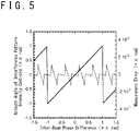
- FIG. 5 is a graph that shows an example of a relationship of a measured value of an azimuth angle 72 of an interference pattern intensity centroid 71 obtained by a phase difference measuring device 6 according to an embodiment and a phase difference measurement error, both with respect to an actual inter-beam phase difference.
- FIG. 5 is a graph that shows an example of a relationship of a measured value of an azimuth angle 72 of an interference pattern intensity centroid 71 obtained by a phase difference measuring device 6 according to an embodiment and a phase difference measurement error, both with respect to an actual inter-beam phase difference.
- the horizontal axis represents the actual phase difference of the test beam L2 with respect to the reference beam L1, that is, the inter-beam phase difference
- the left-side vertical axis represents the measured value of the azimuth angle 72 of the interference pattern intensity centroid 71 obtained by the phase difference measuring device 6 according to the present embodiment
- the right-side vertical axis represents a difference value between them, that is, a measurement error of the phase difference.
- the solid line graph corresponds to the left-side vertical axis
- the dotted line graph corresponds to the right-side vertical axis.
- the measurement error of the inter-beam phase difference according to the present embodiment is included within a range of an order of ⁇ 1.5 ⁇ 10 -5 ⁇ radians.
- the measurement of the inter-beam phase difference between the reference beam L1 and the test beam L2 by the phase difference measuring device 6 according to the present embodiment has an excellent accuracy.
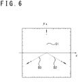
- FIG. 6 is a diagram that shows an example of a measurement result of an angle ⁇ that represents an azimuth angle 72 of an interference pattern intensity centroid 71 obtained by a phase difference measuring device 6 according to an embodiment.
- the horizontal axis and the vertical axis of FIG. 6 correspond to each axis of the cartesian coordinate system x-y in a plane perpendicular to an optical axis of the detection beam L4, respectively.
- FIG. 6 is a diagram that shows an example of a measurement result of an angle ⁇ that represents an azimuth angle 72 of an interference pattern intensity centroid 71 obtained by a phase difference measuring device 6 according to an embodiment.
- the horizontal axis and the vertical axis of FIG. 6 correspond to each axis of the cartesian coordinate system x-y in a plane perpendicular to an optical axis of the detection beam L4, respectively.
- FIG. 7 is a graph that shows an example of measurement error of a phase difference obtained by a phase difference measurement device 6 according to an embodiment.
- the horizontal axis represents the inter-beam phase difference between the reference beam L1 and the test beam L2, and the vertical axis represents a measurement error of the phase.
- FIG. 7 includes a first graph G1, a second graph G2, a third graph G3, and a fourth graph G4.
- the first graph G1 represents a measurement error of the angle ⁇ that corresponds to the inter-beam phase difference in a case where an optical axis direction (pointing) of the test beam L22 is shifted of DLD/4 in a vertical direction (y-axis direction) with respect to the reference beam L12, that is, in a case where a parallelism of the test beam L22 with respect to the reference beam L12 is shifted of DLD/4 in the vertical direction.
- DLD is a Diffraction Limited Divergence (angle) and is herein defined as the below formula with respect to a flat top intensity circular beam.
- DLD 2.44 ⁇ ⁇ / D
- ⁇ represents a wavelength of the shaped detection beam L5 (in fact, a wavelength of each beam that derives from the laser oscillator 2)
- D represents a beam diameter of the shaped detection beam L5.
- the second graph G2 represents a measurement error of the angle ⁇ that corresponds to the inter-beam phase difference in a case where the parallelism of the test beam L22 with respect to the reference beam L12 is shifted of DLD/4 in a horizontal direction (x-axis direction).
- the third graph G3 represents a measurement error of the angle ⁇ that corresponds to the inter-beam phase difference in a case where the parallelism of the test beam L22 with respect to the reference beam L12 is shifted of DLD/5 in a horizontal direction.
- the fourth graph G4 represents a measurement error of the angle ⁇ that corresponds to the inter-beam phase difference in a case where the parallelism of the test beam L22 with respect to the reference beam L12 is shifted of DLD/5 in a vertical direction.
- an absolute value of the measurement error is less than 0.05 ⁇ radians.
- an absolute value of the measurement error is less than 0.03 ⁇ radians.
- a measurement of the inter-beam phase difference between the reference beam L1 and the test beam L2 by the phase difference measuring device 6 according to the present embodiment can suppress an effect due to a shift of the optical axes between the reference beam L12 and the test beam L22, that is, a shift of intersection angle between the reference beam L1 and the test beam L2, in other words a parallelism between the reference beam component L11 and the test beam component L21 in the combined beam L3, to be relatively small.
- the configuration of the beam output apparatus 1 in FIG. 1 is merely an example, and a part of the above-described components may be omitted or replaced to another component, another component may be added, or a positional relationship between components may be changed, as long as the above-described operation can be performed.
- a hologram corresponding to the spiral phase plate 61 may be used instead of the spiral plate 61.
- This hologram may be a phase modulation type hologram or an amplitude modulation type hologram. Since such a technology is disclosed in a non-patent literature 1 ( K. Sueda, G. Miyaji, N. Miyanaga and M. Nakatsuka, "Laguerre-Gaussian beam generated with a multilevel spiral phase plate for high intensity laser pulses", OPTICS EXPRESS, Optical Society of America, July 26, 2004, pp. 3548-3553 ), further detailed description will be omitted.
- FIG. 8 is a diagram that shows an example of a hologram 7 that can generate a spiral phase distribution.
- FIG. 9A is a perspective view that shows a configuration example of a multilevel spiral phase plate 610 according to an embodiment.
- the multilevel spiral phase plate 610 shown in FIG. 9A has a function of giving a spiral step-like phase distribution, wherein each step has a fan shape of which bottom surface has a central angle of ⁇ /8 radians, and has a shape in which a total of sixteen prisms, that have thicknesses different from each other, are gathered so that each bottom surface is arranged on a same plane and a central angle of each bottom surface is in contact with each other.
- a difference between a thickness of each prism with the fan-shape bottom surface and the thickness of the prism with the fan-shape bottom surface of which the thickness is the thinnest is a multiple of ⁇ /8 radians, and is distributed within a range from 0 radian to 15 ⁇ /8 radians.
- each prism with the fan-shape bottom surface is arranged in an order of thickness thereof to rotate the central angle thereof.
- the multilevel spiral phase plate 610 shown in FIG. 9A is obtained by approximating the spirally curbed surface of the spiral phase plate 61 shown in FIG. 2A with a group of a plurality of parallel planes.
- the multilevel spiral phase plate 610 that is configured as above can be manufactured cheaper and easier compared to the spiral phase plate 61 that has a spirally curbed surface. Since the multilevel spiral phase plate 610 shown in FIG. 9A has a total of sixteen different thicknesses, it may be referred to as a sixteen-step spiral phase plate. Although the number of the steps in the example of FIG. 9A is sixteen, it should be noted that this value is merely an example and does not limit the present embodiment.
- FIG. 9B is a diagram that shows an example of a phase distribution in a cross section that is perpendicular to an optical axis direction of a reference beam L1 that has passed through the multilevel spiral phase plate 610 shown in FIG. 9A . While in the phase distribution shown in FIG. 2B , that is obtained in the case where the spiral phase plate 61 is used, the phase continuously changes in a direction of rotation around the optical axis, in the phase distribution shown in FIG. 9B , the phase in the phase distribution also changes stepwise at positions where the thickness of the multilevel spiral phase plate 610 changes stepwise.
- a laser beam that has such a phase distribution will be referred to as a laser beam having a multilevel spiral wavefront, for convenience.
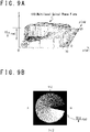
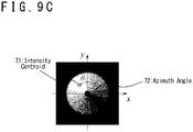
- FIG. 9C is a diagram that shows an example of an interference pattern generated by a reference beam that has passed through the multilevel spiral phase plate 610 shown in FIG. 9A and a test beam. While the interference intensity continuously changed in a direction of rotation around an optical axis in the optical intensity distribution of the interference pattern shown in FIG. 4B , that is obtained in case where the spiral phase plate 61 is used, the interference intensity also changes stepwise at positions where the thickness of the multilevel spiral phase plate 610 changes stepwise in the optical intensity distribution of the interference pattern shown in FIG. 9C .
- FIG. 9D is a graph that shows an example of a relationship of a measured value of an azimuth angle 72 of an interference pattern intensity centroid 71 obtained by a phase difference measuring device 6 that uses the multilevel spiral phase plate 610 shown in FIG. 9A and a phase difference measurement error, both with respect to an actual phase difference of the test beam with respect to the reference beam that has passed through the multilevel spiral phase plate 610.
- the graph in FIG. 9D is different in the phase difference measurement error, that is represented by the dotted line, in comparison with the graph shown in FIG. 5 . That is, the measurement error shown in FIG. 9D is included in the range from 0 radian to an order of 0.007 ⁇ radians. Although this range is wider than the measurement error shown in FIG.
- the measurement of the phase difference between the reference beam L1 and the test beam L2 can be performed with a sufficiently high accuracy even if the spiral phase plate 61 included in the beam output apparatus 1 shown in FIG. 1 is replaced with the multilevel spiral phase plate 610.
- the spiral phase plate 61 shown in FIG. 1 , the hologram 7 shown in FIG. 8 and the multilevel spiral phase plate 610 shown in FIG. 9A are all a phase conversion device that converts a laser beam that passes therethrough so that a cross section of this laser beam, that is included in an arbitrary virtual plane perpendicular to an optical axis of this laser beam that has passed therethrough, includes a phase distribution of one cycle.
- FIG. 10 is a diagram that shows a configuration example of a beam output apparatus 1 according to an embodiment.
- the beam output apparatus 1 according to the present embodiment is approximatively equivalent to an apparatus in that four beam output apparatuses 1 shown in FIG. 1 are prepared and integrated.
- the beam output apparatus 1 according to the present embodiment generates a laser beam L0 to be seed light and splits it into a reference beam L1 and a test beam L2, and in addition, splits the test beam L2 into four test beams L2A, L2B, L2C and L2D.
- a cross-sectional area of the reference beam L1 is enlarged by a beam expander 44, and spiral phase plates 61A, 61B, 61C and 61D are arranged in the enlarged reference beam to equivalently generate four reference beams so as to match optical paths of the test beams L2A, L2B, L2C and L2D that are reflected by the beam splitter 62.
- four spiral phase plates 61A, 61B, 61C and 61D may be appropriately arranged so that four reference beams that have respectively passed through the four spiral phase plates 61A, 61B, 61C and 61D have a same phase.
- the beam output apparatus 1 measures four phase differences between four reference beams L1 and four test beams L2, performs a feedback control of the phases of four test beams L2A, L2B, L2C and L2D based on this measurement result via four detector signals DSA, DSB, DSC and DSD and four phase control signals CSA, CSB, CSC and CSD, and outputs a combined beam L3 constituted of components of four test beams L2A, L2B, L2C and L2D that are respectively transmitted through the beam splitter 62.
- the beam output apparatus 1 in FIG. 10 is provided with a laser oscillator 2, a beam splitter 3, a reference beam generation section 4, a test beam generation section 5 and a phase difference measurement device 6.
- the reference beam generation section 4 is provided with an optical path length adjustment section 42, a reflector 43 and the beam expander 44.
- the optical path length adjustment section 42 in FIG. 10 is provided with four mirrors 42A, 42B, 42C and 42D, this value is merely an example and does not limit the present embodiment.
- the beam expander 44 may be configured similarly to the beam expander 44 shown in FIG. 1 .
- the test beam generation section 5 is provided with a controller 51, a beam splitter 52, four phase controllers 53A, 53B, 53C and 53D, four beam expanders 54A, 54B, 54C and 54D, and four amplifiers 55A, 55B, 55C and 55D.
- a controller 51 a beam splitter 52
- four phase controllers 53A, 53B, 53C and 53D four beam expanders 54A, 54B, 54C and 54D
- amplifiers 55A, 55B, 55C and 55D When four beam expanders 54A, 54B, 54C and 54D are not distinguished, they will be simply referred to as amplifiers 55.
- the phase difference measurement device 6 is provided with four spiral phase plates 61A, 61B, 61C and 61D that have a same material and a same thickness; a beam splitter 62; four apertures 63A, 63B, 63C and 63D; four four-quadrant detectors 64A, 64B, 64C and 64D; and four processors 65A, 65B, 65C and 65D.
- spiral phase plates 61 When four spiral phase plates 61A, 61B, 61C and 61D are not distinguished, they will be simply referred to as spiral phase plates 61.
- apertures 63A, 63B, 63C and 63D When four apertures 63A, 63B, 63C and 63D are not distinguished, they will be simply referred to as apertures 63.
- processors 65 When four four-quadrant detectors 64A, 64B, 64C and 64D are not distinguished, they will be simply referred to as four-quadrant detectors 64. When four processors 65A, 65B, 65C and 65D are not distinguished, they will be simply referred to as processors 65.
- the optical path length adjustment section 42 can adjust an optical path length of the reference beam L1.
- the optical path length adjustment section 42 receives the reference beam L1 outputted from the beam splitter 3, reflects it by use of four mirrors 42A, 42B, 42C and 42D in this order, and outputs it to the reflector 43.
- the length of the optical path through which the reference beam L1 passes via the mirrors 42A, 42B, 42C and 42D can be adjusted, and a difference of optical path length between the reference beam L1, that is included in the detection beam L4 that arrives to the four-quadrant detector 64, and the test beam L2 can be brought closer to zero.
- this optical path length difference is shorter than a distance obtained by multiplying 1/10 of a pulse time width by the speed of light. It should be noted that, when the laser beam L0 is a continuous wave, it is preferable that this optical path length difference is shorter than a fraction of a coherence length and it is more desirable that this optical path length difference is shorter than 1/10 of the coherence length.
- the beam splitter 52 is a splitting device that splits the test beam L2 into a plurality of test beams L2A, L2B, L2C and L2D.
- the beam splitter 52 is provided with mirrors 52A, 52C, 52D, 52F, 52G, 52H, 521, 52K, 52L and 52M, and half mirrors 52B, 52E and 52J.
- a part of the test beam L2 outputted from the beam splitter 3 is reflected or transmitted by the mirror 52A, the half mirror 52B, the mirrors 52C, 52D, the half mirror 52E, the mirrors 52F and 52G in this order and arrives to the phase controller 53A as the test beam L2A.
- a part of the test beam L2 outputted from the beam splitter 3 is reflected or transmitted by the mirror 52A, the half mirror 52B, the mirrors 52C, 52D, the half mirror 52E, and the mirror 52H in this order and arrives to the phase controller 53B as the test beam L2B.
- a part of the test beam L2 outputted from the beam splitter 3 is reflected or transmitted by the mirror 52A, the half mirror 52B, the mirror 521, the half mirror 52J, and the mirrors 52L and 52M in this order and arrives to the phase controller 53C as the test beam L2C.
- test beam L2 outputted from the beam splitter 3 is reflected or transmitted by the mirror 52A, the half mirror 52B, the mirror 521, the half mirror 52J, and the mirror 52K in this order and arrives to the phase controller 53D as the test beam L2D.
- the test beam L2A arrives to the four-quadrant detector 64A via the phase controller 53A, the beam expander 54A, the amplifier 55A, and the beam splitter 62.
- the test beam L2B arrives to the four-quadrant detector 64B via the phase controller 53B, the beam expander 54B, the amplifier 55B, and the beam splitter 62.
- the test beam L2C arrives to the four-quadrant detector 64C via the phase controller 53C, the beam expander 54C, the amplifier 55C, and the beam splitter 62.
- the test beam L2D arrives to the four-quadrant detector 64D via the phase controller 53D, the beam expander 54D, the amplifier 55D, and the beam splitter 62.
- a part of the reference beam L1 outputted from the beam expander 44 passes through the spiral phase plate 61A, the beam splitter 62, and the aperture 63A and arrives to the four-quadrant detector 64A.
- Another part of the reference beam L1 outputted from the beam expander 44 passes through the spiral phase plate 61B, the beam splitter 62, and the aperture 63B and arrives to the four-quadrant detector 64B.
- a still another part of the reference beam L1 outputted from the beam expander 44 passes through the spiral phase plate 61C, the beam splitter 62, and the aperture 63C and arrives to the four-quadrant detector 64C.
- a still another part of the reference beam L1 outputted from the beam expander 44 passes through the spiral phase plate 61D, the beam splitter 62, and the aperture 63D, and arrives to the four-quadrant detector 64D.
- FIG. 11 is a diagram that partially shows a configuration example of the beam output apparatus 1 according to an embodiment.
- the beam output apparatus 1 in FIG. 11 is obtained by adding following changes to the beam output apparatus 1 in FIG. 10 . That is, two beam splitters 62A and 62B are used instead of the beam splitter 62 in FIG. 10 .
- the arrangement of the beam expander 54 and the amplifier 55 is adjusted so that the test beams L2A to L2D becomes parallel to each other.
- the arrangement of the beam expander 44 and the parallelism of the beam splitters 62A and 62B are adjusted so that the optical axes of the reference beam L1 and the test beams L2 become parallel.
- the test beams L2 outputted from the amplifiers 55 are made incident to the four-quadrant detectors 64 via two beam splitters 62A and 62B.
- the test beams L2 can be significantly dimmed because the number of the beam splitters is increased compared to the case of FIG. 10 .
- the optical intensity of the combined beam L3 can be made higher.
- the component of the reference beam L1 that is not transmitted by the beam splitter 62B can be outputted to a direction different from the combined beam L3. Therefore, since the reference beam L1 is not mixed in the combined beam L3 at all, in can be expected that the quality of the combined laser beam is further improved.
- FIG. 12 is a diagram that shows a configuration example of a beam output apparatus 10 according to an embodiment that combines two beams on a same optical path.
- the beam output apparatus 10 generates a high-power and high-quality laser beam by splitting the laser beam L0 to be seed light by the beam splitter 3 into a first beam L10 and a second beam L20, amplifying both the first beam L10 and the second beam L20 and combining them, measuring the inter-beam phase difference between the first beam L10 and the second beam L20, and performing a feedback control of the phase of the second beam L20 to match the phase of the first beam L10.
- the target of the matching may be another phase obtained by adding a predetermined phase difference to the phase of the first beam L10.
- the beam output apparatus 10 of FIG. 12 is provided with a laser oscillator 2, a beam splitter 3, a mirror 31, and a beam combination unit 11.
- the beam combination unit 11 is provided with a first beam generation section 14, a second beam generation section 15, a mirror 111, a polarizing beam splitter 112, and a phase difference measuring device 16.
- the first beam generation section 14 is provided with a half-wave plate 41, an optical path length adjustment section 42, a beam expander 54A, and an amplifier 55A.
- the second beam generation section 15 is provided with a controller 51, a phase controller 53, a beam expander 54B, and an amplifier 55B.
- the phase difference measuring device 16 is provided with a beam splitter 161, a half-wave plate 162, a polarizing beam splitter 163, a beam splitter 164, a power monitor 165, a polarizing beam splitter 166, an optical path length adjustment section 167, a mirror 168, a half-wave plate 169, a mirror 170, and a phase difference measuring device 6. Since the configuration of the phase difference measuring device 6 is the same as in the case of FIG. 1 , further detailed description thereof will be omitted.
- the laser oscillator 2 outputs the laser beam L0 that is to be seed light.
- the beam splitter 3 splits the laser beam L0 into the first beam L10 and the second beam L20.
- the first beam generation section 14 receives, amplifies, and outputs the first beam L10.
- the half-wave plate 41 rotates the linear polarization direction of the first beam L10 of ⁇ /2 radians.
- the optical path length adjustment section 42 adjusts the optical path length difference between the first beam L10 and the second beam L20 at the polarizing beam splitter 112 to be a distance shorter than a distance obtained by multiplying 1/10 of the pulse time width by the speed of light.
- the optical path length adjustment section 42 adjusts the optical path length difference between the first beam L10 and the second beam L20 at the polarizing beam splitter 112 to be a distance shorter than a fraction of the coherence length.
- the beam expander 54A enlarges the cross-sectional area of the first beam L10.
- the amplifier 55A amplifies the optical intensity of the first beam L10.
- the second beam generation section 15 receives the second beam L20 via the mirror 31, amplifies it and outputs it.
- the controller 51 generates the phase control signal CS based on the detector signal DS supplied from the phase difference measuring device 6.
- the phase controller 53 adjusts the phase of the second beam L20 based on the phase control signal CS.
- the beam expander 54B enlarges the cross-sectional area of the second beam L20.
- the amplifier 55B amplifies the optical intensity of the second beam L20.
- the linear polarization directions are perpendicular between the first beam L10 outputted from the first beam generation section 14 and the second beam L20 outputted from the second beam generation section 15.
- a supposition in that the first beam L10 is s-polarized with respect to the polarizing beam splitter 112 and the second beam L20 is p-polarized, and a supposition in that the intensities of the first beam L10 and the second beam L20 are the same.
- the polarized beam splitter 112 combines the first beam L10, that is outputted from the first beam generation section 14 and reflected by the mirror 111, and the second beam L20, that is outputted from the second beam generation section 15, and outputs the combined beam L30.
- the combined beam L30 includes a component derived from the s-polarized first beam L10 and a component derived from the p-polarized second beam L20. That is, when the phases of the s-polarized beam and the p-polarized beam are the same, the combined beam is linear-polarized with an inclination of 45 degrees, and is elliptically polarized or circularly polarized in other cases.
- the phase difference measuring device 16 receives the combined beam L30 outputted from the polarizing beam splitter 112, measures the phase difference between the first beam L10 and the second beam L20 both included the combined beam L30, outputs the detector signal DS for performing the feedback control to the phase of the second beam L20 based on the result of this measurement, and gives, to the combined beam L30, linear polarization and polarization angle that are appropriate to the polarizing beam splitter 163, as a result of the phase feedback control.
- the beam splitter 161 splits the combined beam L30 into a combined beam L31 and a detection beam L40.
- the half-wave plate 162 rotates respective polarization directions of the s-polarized component and the p-polarized component of the combined beam L30 of 45 degrees.
- the linear polarization direction, or a main axis direction of the ellipse in case of elliptical polarization, of the combined beam L31 of which the polarization has been rotated matches the p-polarization of the polarizing beam splitter 163, and the output beam L32 is obtained.
- the component that is s-polarized with respect to the polarizing beam splitter 163, of the polarized component of the combined beam L31, of which the polarization has been rotated, is outputted to the dump port as the dump beam L33.
- the beam splitter 164 takes out a part of the output beam L32 as a monitor beam L34 and the power monitor 165 monitors the optical intensity of the output beam L35.
- the beam splitter 164 splits, a most part (for example: more than 99%) of the output beam L32 may be transmitted as the output beam L35, and a slight part (for example: less than 1%) of the output beam L32 may be split as the monitor beam L34.
- the phases of the s-polarized beam and the p-polarized beam are the same just after the polarizing beam splitter 112, the power received by the power monitor 165 becomes maximal.
- the polarizing beam splitter 166 splits the detection beam L40, that is split by the beam splitter 161, into a s-polarized first detection beam L41 (a part of the first beam L10 included in the combined beam L30, obtained as a detection beam) and a p-polarization second detection beam L42 (a part of the second beam L20 included in the combined beam L30, obtained as a detection beam).
- the half-wave plate 169 rotates the linear polarization direction of the s-polarized first detection beam L41 of 90 degrees, and outputs the p-polarized first detection beam L41.
- the first detection beam L41 is inputted to the four-quadrant detector 64 of the phase difference measuring device 6, via the mirror 170, the spiral phase plate 61, the beam splitter 62, and the aperture 63.
- the second detection beam L42 is also inputted to the four-quadrant detector 64 of the phase difference measuring device 6, via the optical path length adjustment section 167, the mirror 168, the beam splitter 62, and the aperture 63.
- the linear polarization directions of the first detection beam L41 and the second detection beam L42 at the four-quadrant detector 64 are the same, and therefore a visibility of the interference pattern generated by the first detection beam L41 and the second detection beam L42 becomes higher.
- the beam splitter 62 in the embodiment shown in FIG. 12 may be a half mirror.
- the beam output apparatus 10 can split the laser beam L0 that is to be seed light into two laser beams, amplify each of the split laser beams by two amplifiers 55A and 55B, and use a most part thereof as the output beam L35 on an identical optical path, it is expected that a high-power laser beam, that is a combination of two to the power of n (n is an integer) beams on an identical optical path, can be generated by a deduction of a plurality of combinations.
- n is an integer
- FIG. 13 is a diagram that shows a configuration example of a beam output apparatus 100 according to an embodiment.
- the beam output apparatus 100 in FIG. 13 is provided with two beam output apparatuses 10 in FIG. 12 , measures a phase difference between two combined beams L35A and L35B outputted from those two beam output devices 140 and 150, performs a feedback control of a phase of one combined beam L35B, and can combine two combined beams L35A and L35B with matched phases.
- the beam output apparatus 100 is provided with a laser oscillator 2, a beam splitter 30, a mirror 310, a first beam output device 140, a second beam output device 150, a mirror 111, a polarizing beam splitter 112, and a phase difference measuring device 160 for measuring a phase difference between a first combined beam L35A and a second combined beam L35B.
- the first beam output device 140 is provided with a beam splitter 3, a mirror 31, and a beam combination unit 11A.
- the second beam output device 150 is provided with a controller 51 for controlling the phase of the second combined beam L35B, a phase controller 53, a beam splitter 3, a mirror 31, and a beam combination unit 11B.
- the beam output apparatus 100 in FIG. 13 operates in a same way as the beam output apparatus 10 in FIG. 12 .
- the laser oscillator 2, the beam splitter 30, and the mirror 310 in FIG. 13 correspond to the laser oscillator 2, the beam splitter 3, and the mirror 31 in FIG. 12 , respectively.
- each of the first beam output device 140 and the second beam output device 150 in FIG. 13 is provided with the beam combination unit 11 in FIG. 12 .
- the configuration that is provided to the second beam output device 150 and corresponds to the beam combination unit 11 in FIG. 12 is shown as a beam combination unit 11B.
- the mirror 111, the polarizing beam splitter 112, and the phase difference measuring device 160 in FIG. 13 correspond to the mirror 111, the polarizing beam splitter 112, and the phase difference measuring device 16 in FIG. 12 , respectively.
- the beam splitter 3 and the mirror 31 in FIG. 13 correspond to the beam splitter 3 and the mirror 31 in FIG. 12
- the controller 51 and the phase controller 53 in FIG. 13 have same functions as the controller 51 and the phase controller 53 in FIG. 12 , respectively.
- each of the two beam combination units 11A and 11B operates in a same way as the beam combination unit 11 in FIG. 12 . That is, each unit splits an inputted laser beam into two beams by use of the beam splitter 3, amplifies each of those two laser beams, measures the phase difference between the two amplified laser beams, performs a feedback control of the phase of one of the laser beams based on the result of this measurement, and outputs a beam that is a combination of the two laser beams with matched phases.
- the polarizing beam splitter 112 and the phase difference measurement device 160 operate in same ways as the polarizing beam splitter 112 and the phase difference measurement device 16 in FIG. 12 . That is, the polarizing beam splitter 112 in FIG. 13 outputs a third combined beam that is a combination of a first combined beam, that is outputted from the beam combination unit 11A and arrives via the mirror 111, and a second combined beam that is outputted from the beam combination unit 11B.
- the phase difference measuring device 160 measures a phase difference between at least a part of the first combined beam and at least a part of the second combined beam that are included in the third combined beam, and generates a detector signal for performing a feedback control of the phase of the second combined beam based on the result of this measurement.
- the controller 51 generates the phase control signal based on this detector signal, and the phase controller 53 controls the phase of the laser beam that arrives via the mirror 310 based on this phase control signal.
- the beam output apparatus 100 in FIG. 13 can split the laser beam L0 into four beams to amplify each of them separately, match the phases thereof, and combine. Furthermore, by making the configuration of the beam output apparatus 100 in FIG. 13 a recursive nesting structure, the laser beam L0 can be split into eight beams, each of which is separately amplified, matched in phases, and combined. Similarly, by repeating the recursive nesting structure, the laser beam L0 can be split into two to power of an arbitrary number, each of which is separately amplified, matched in phases, and combined, and therefore a laser beam with higher power and higher quality can be generated.
- phase difference measuring device 6 is understood for example as below.
- phase difference measuring device 6 can measure an inter-beam phase difference of a test beam with respect to a reference beam and adjust it, by use of the phase conversion device 61, 7, 610 and the detection device 60.
- the phase conversion device 61, 7, 610 has a function of converting a first laser beam L1 that passes therethrough so that the first laser beam L1 includes a phase distribution of one cycle in an azimuth direction in a cross section of the first laser beam L1 that has passed therethrough included in an arbitrary virtual plane perpendicular to an optical axis of the first laser beam L1.
- a device that converts the phase distribution in such a way there is an optical device such that a phase of a transmitted beam is different according to a part of the laser beam that passes therethrough.
- the phase conversion device 61, 7, 610 represents a superordinate concept of the spiral phase plate 61, the hologram 7, and the multilevel spiral phase plate 610.
- the detection device 60 has a function of detecting an azimuth angle 72 of an intensity centroid 71 of an interference pattern and detecting an inter-beam phase difference of a second laser beam L2 with respect to the first laser beam L1 based on the azimuth angle 72.
- the interference pattern is generated by a shaped detection beam L5 obtained by cutting out a part of a cross section of a detection beam L4 into a shape of a circle with a point, where the cross section of the detection beam L4 and an optical axis of the phase conversion device 61, 7, 610 intersect, as a center thereof.
- the cross section of the detection beam is perpendicular to an optical axis A4 of the detection beam L4.
- the detection beam L4 is obtained by combining a reference beam L12 that is a first partial intensity laser beam and a test beam L22 that is a second partial intensity laser beam on a same optical path.
- the first partial intensity laser beam has at least a part of an intensity component of the first laser beam L1 that has passed through the phase conversion device 61, 7, 610.
- the second partial intensity laser beam has at least a part of an intensity component of the second laser beam L2 derived from a laser beam L0 as seed light from which the first laser beam L1 derives.
- a phase difference measuring device 6 according to a second aspect is the phase difference measuring device 6 according to the first aspect, and is further provided with a sensor device 64 and a processor 65.
- a phase difference measuring device 6 according to a third aspect is the phase difference measuring device 6 according to the second aspect, and is further provided with a four-quadrant detector 64.
- the phase difference measuring device 6 according to a fourth aspect is the phase difference measuring device 6 according any one of the first to third aspects, and is further provided with the spiral phase plate 61.
- a phase difference measuring device 6 according to a fifth aspect is the phase difference measuring device 6 according to any one of the first to third aspects, and is further provided with the hologram 7 of the spiral phase plate 61.
- a phase difference measuring device 6 according to a sixth aspect is the phase difference measuring device 6 according to any one of the first to third aspects, and is further provided with the multilevel spiral phase plate 610.
- a beam output apparatus 1, 10, 100 according to a first aspect is provided with a first beam splitter 3, 30, a phase conversion device 61, 7, 610, a detection device 60, and a phase controller 53.
- the beam output apparatus 1, 10, 100 can generate a high-power and high-quality laser beam by use of the first beam splitter 3, 30, the phase conversion device 61, 7, 610, the detection device 60, and the phase controller 53.
- the first beam splitter 3, 30 has a function of splitting a laser beam L0 that is to be seed light into a first laser beam L1 and a second laser beam L2.
- the phase conversion device 61, 7, 610 has a function of converting a first laser beam L1 that passes therethrough so that the first laser beam L1 includes a phase distribution of one cycle in an azimuth direction in a cross section of the first laser beam L1 that has passed therethrough included in an arbitrary virtual plane perpendicular to an optical axis of the first laser beam L1.
- a device that converts the phase distribution in such a way there is an optical device such that a phase is different according to a part of the laser beam that passes therethrough.
- the detection device 60 has a function of detecting an azimuth angle 72 of an intensity centroid 71 of an interference pattern and detecting an inter-beam phase difference of a second laser beam L2 with respect to the first laser beam L1 based on the azimuth angle 72.
- the interference pattern is generated by a shaped detection beam L5 obtained by cutting out a part of a cross section of a detection beam L4 into a shape of a circle with a point, where the cross section of the detection beam L4 and an optical axis of the phase conversion device 61, 7, 610 intersect, as a center thereof.
- the cross section of the detection beam is perpendicular to an optical axis A4 of the detection beam L4.
- the detection beam L4 is obtained by combining a reference beam L12 that is a first partial intensity laser beam and a test beam L22 that is a second partial intensity laser beam on a same optical path.
- the first partial intensity laser beam has at least a part of an intensity component of the first laser beam L1 that has passed through the phase conversion device 61, 7, 610.
- the second partial intensity laser beam has at least a part of an intensity component of the second laser beam L2.
- the phase controller 53 has a function of controlling the phase of the second laser beam L2 based on the measured value of the azimuth angle 72. As a result, when combining the first laser beam L1 as a phase reference and the second laser beam L2, the inter-beam phase difference between the both beams can be adjusted. As a device having such a function, there is a phase controller that can adjust the phase of the laser beam that passes therethrough.
- a beam output apparatus 1, 10, 100 according to a second aspect is the beam output apparatus 1, 10, 100 according to the first aspect and is further provided with a sensor device 64 and a processor 65.
- Such optical intensities P 1 , P 2 , P 3 and P 4 may be the optical intensities P 1 , P 2 , P 3 and P 4 of the four quadrants of the interference pattern.
- a beam output apparatus 1, 10, 100 according to a third aspect is the beam output apparatus 1, 10, 100 according to the second aspect, and is further provided with a four-quadrant detector 64. As a result, there is an effect in that the detection of the azimuth angle 72 can be realized by four sensors with high accuracy.
- a beam output apparatus 1, 10, 100 according to a fourth aspect is the beam output apparatus 1, 10, 100 according to any one of the first to third aspects, and is further provided with the spiral phase plate 61.
- a beam output apparatus 1, 10, 100 according to a fifth aspect is the beam output apparatus 1, 10, 100 according to any one of the first to third aspects, and is further provided with the hologram 7 of the spiral phase plate 61.
- a beam output apparatus 1, 10, 100 according to a sixth aspect is the beam output apparatus 1, 10, 100 according to any one of the first to third aspects, and is further provided with the multilevel spiral phase plate 610.
- a beam output apparatus 1, 10, 100 according to a seventh aspect is the beam output apparatus 1, 10, 100 according to any one of the first to sixth aspects and is further provided with an amplifier 55.
- the amplifier 55 amplifies the second laser beam L2.
- a beam output apparatus 1, 10, 100 according to an eighth aspect is the beam output apparatus 1, 10, 100 according to the first to seventh aspects and is further provided with a splitting device 52 and a plurality of amplifiers 55.
- the splitting device 52 has a function of splitting the second laser beam L2 into a plurality of test beams L2A, L2B, L2C and L2D that are a plurality of second partial intensity laser beams, each of which has a part of intensity component of the second laser beam L2.
- a device that has such a function there is a combination 52 of mirrors and half mirrors, or the like.
- the plurality of amplifiers 55 respectively amplify the plurality of test beams (the second partial intensity laser beams) L2A, L2B, L2C and L2D.
- the phase conversion device 61A, 61B, 61C and 61D according to the eighth aspect includes a plurality of phase conversion devices 61A, 61B, 61C and 61D that are arranged so that a plurality of first partial cross section laser beams, that are obtained by cutting out the first laser beam L1 by parts of beam cross sections, respectively pass therethrough.
- Each of the plurality of phase conversion devices 61A, 61B, 61C and 61D has a function of converting each of the plurality of first partial cross section laser beams that passes therethrough, so that the each first partial cross section laser beam includes a phase distribution of one cycle in an azimuth direction in a cross section of the each first partial cross section laser beam that has passed therethrough included in an arbitrary virtual plane perpendicular to an optical axis of the each first partial cross section laser beam.
- the detection device 60 has a function of detecting an azimuth angle 72 of an intensity centroid 71 of each of a plurality of interference patterns by a plurality of shaped detection beams obtained by cutting out a part of a cross section, that is perpendicular to an optical axis of each of a plurality of detection beams, of the plurality of detection beams obtained by combining the plurality of first partial cross section laser beams and the plurality of test beams (second partial intensity laser beams), respectively on same optical paths into a shape of a circle with a point, where the cross section of the each detection beam and an optical axis of the each phase conversion devices 61A, 61B, 61C and 61D intersect, as a center thereof, and detecting an inter-beam phase difference of each of the plurality of test beams (second partial intensity laser beams) L2A, L2B, L2C and L2D with respect to the plurality of first partial cross section laser beams based on the azimuth angle 72.
- the phase controllers 53A, 53B, 53C and 53D has a function of controlling the phase of each of the test beams (second partial intensity laser beams) L2A, L2B, L2C and L2D based on each of the inter-beam phase differences.
- a beam output apparatus 1, 10, 100 according to a ninth aspect is the beam output apparatus 1, 10, 100 according to the first to eighth aspects and is provided with a half-wave plate 41, an amplifier 55A that is different from the amplifier 55 according to the seventh or eighth aspect, a polarizing beam splitter 112, a second beam splitter 161, and a third beam splitter 166.
- the half-wave plate 41 rotates a linear polarization direction of at least one of the first laser beam L10 and the second laser beam L20.
- the amplifier 55A that is different from the amplifier 55 according to the seventh or eighth aspect, amplifies the second laser beam L20.
- the polarizing beam splitter 112 combines the first laser beam L10 and the second laser beam L20, of which the linear polarization directions are different from each other, to generate a third laser beam L30.
- the second beam splitter 161 splits the third laser beam L30 into a combined laser beam L31 and a detection laser beam L40.
- the third beam splitter 166 splits the detection laser beam L40 into a first detection laser beam L41 and a second laser beam L42.
- the detection device 60 detects the azimuth angle 72 of the intensity centroid 71 of the interference pattern generated by the first detection laser beam L41 and the second detection laser beam L42. As a result, there is an effect in that a laser beam with a high quality and a higher power can be generated, since the beam that was amplified as a reference beam for generating an interference pattern can be used and two beams can be combined on a same optical path.
- a phase difference measuring method is provided with a first step of converting a first laser beam L1 that has passed through a phase conversion device 61, 7, 610 to include a phase distribution of one cycle in an azimuth direction in a cross section of the first laser beam L1 that has passed therethrough included in an arbitrary virtual plane perpendicular to an optical axis of the first laser beam L1, and a second step of detecting an azimuth angle 72 of an intensity centroid 71 of an interference pattern and detecting an inter-beam phase difference of a second laser beam L2 with respect to the first laser beam L1 based on the azimuth angle 72.
- the interference pattern is generated by a shaped detection beam L5 obtained by cutting out a part of a cross section of the detection beam L4 into a shape of a circle with a point, where the cross section of the detection beam L4 and an optical axis of the phase conversion device 61, 7, 610 intersect, as a center thereof.
- the cross section of the detection beam L4 is perpendicular to an optical axis A4 of a detection beam L4.
- the detection beam L4 is obtained by combining a reference beam L12 that is a first partial intensity laser beam and a test beam L22 that is a second partial intensity laser beam on a same optical path.
- the first partial intensity laser beam has at least a part of an intensity component of the first laser beam L1 that is converted.
- the second partial intensity laser beam has at least a part of an intensity component of the second laser beam L2 derived from a laser beam L0 as seed light from which the first laser beam L1 derives.
- the phase difference measuring method has an effect in that a high-power and high-quality laser beam can be generated by the first step and the second step.
- the first step has a function of converting a first laser beam L1 that passes therethrough so that the first laser beam L1 that has passed therethrough includes a phase distribution of one cycle in an azimuth direction in a cross section of the first laser beam L1 included in an arbitrary virtual plane perpendicular to an optical axis of the first laser beam L1 that has passed therethrough.
- a function may be realized by use of an optical device such that a phase is different according to a part of a laser beam that passes therethrough.
- an optical device there are a spiral phase plate 61, a hologram 7 corresponding to the spiral phase plate 61, a multilevel spiral phase plate 610, or the like.
- the second step has a function of detecting an azimuth angle 72 of an intensity centroid 71 of an interference pattern generated by a shaped detection beam L5 obtained by cutting out a part of a cross section, that is perpendicular to an optical axis A4 of a detection beam L4, of the detection beam L4 obtained by combining a reference beam L12 that is a first partial intensity laser beam, that has at least a part of an intensity component of the converted first laser beam L1, and a test beam L22 that is a second partial intensity laser beam, that has at least a part of an intensity component of a second laser beam L2 derived from a laser beam L0 as seed light from which the first laser beam L1 derives, on a same optical path, into a shape of a circle with a point, where the cross section of the detection beam L4 and an optical axis of the phase conversion device 61, 7, 610 intersect, as a center thereof, and detecting an inter-beam phase difference of the second laser beam L2 with respect to the first laser beam
Landscapes
- Physics & Mathematics (AREA)
- General Physics & Mathematics (AREA)
- Optics & Photonics (AREA)
- Spectroscopy & Molecular Physics (AREA)
- Electromagnetism (AREA)
- Engineering & Computer Science (AREA)
- Plasma & Fusion (AREA)
- Length Measuring Devices By Optical Means (AREA)
- Lasers (AREA)
Abstract
Description
- The present invention relates to a phase difference measuring device, a beam output apparatus and a phase difference measuring method, and can be suitably used as a phase difference measuring device, a beam output apparatus and a phase difference measuring method for a laser beam, for example.
- High-quality and high-power laser light is required in fields such as laser processing, scientific research, nuclear fusion, space debris removal, and security. However, due to factors such as heat generation, optical damage, and non-linear optical effects, there is a limit to an output that can be achieved as a single laser beam. Therefore, the technology for combining a plurality of laser beams is being studied to increase the output power.
- Herein, when combining a plurality of laser beams, it is preferable to match a phase of each laser beam. Therefore, a device, a process, or the like for temporal modulation and/or demodulation (frequency shift, phase modulation, or the like) of each laser beam is required.
- In connection with the above, Patent Literature 1 (
US 2009/0134310 A1 ) discloses a laser system that combines a plurality of laser beams. In this laser system, a frequency shift is applied to each laser beam in order to calculate a phase of each laser beam. - Patent Literature 2 (
Japanese Patent Publication No. 2014-216418 - In addition, in order to respond to a change in beam intensity, it is necessary to observe an interference pattern by use of a plurality of sensors and calculate. When a pointing of a laser beam changes, an appearance of interference fringes changes (for example: the interference fringes are tilted, a spacing between the interference fringes changes, or the like). In order to respond to such changes, it is necessary to observe the interference pattern by use of a plurality of sensors.
- In connection to the above, Patent Literature 3 (
Japanese Patent No. 6071202 - In addition, Non-Patent Literature 1 (K. Sueda, G. Miyaji, N. Miyanaga and M. Nakatsuka, "Laguerre-Gaussian beam generated with a multilevel spiral phase plate for high intensity laser pulses", OPTICS EXPRESS, Optical Society of America, July 26, 2004, pp. 3548-3553.) discloses a phase distribution of a 16-step spiral phase plate, a prototype example, an interference pattern generated by a beam with 16-step spiral phase plate and a reference beam.
-
- [Patent Literature 1]
US 2009/0134310 A1 - [Patent Literature 2]
Japanese Patent Publication No. 2014-216418 - [Patent Literature 3]
Japanese Patent No. 6071202 - [Non-Patent Literature 1] K. Sueda, G. Miyaji, N. Miyanaga and M. Nakatsuka, "Laguerre-Gaussian beam generated with a multilevel spiral phase plate for high intensity laser pulses", OPTICS EXPRESS, Optical Society of America, July 26, 2004, pp. 3548-3553.
- Phase difference between laser beams will be detected or measured in order to generate a high-power and high-quality laser beam. Other objectives and new features will be clarified by disclosures of the present description and attached drawings.
- A phase difference measuring device according to an embodiment is provided with a phase conversion device and a detection device. The phase conversion device converts a first laser beam that passes therethrough so that the first laser beam includes a phase distribution of one cycle in an azimuth direction in a cross section of the first laser beam that has passed therethrough included in an arbitrary virtual plane perpendicular to an optical axis of the first laser beam. The detection device detects an azimuth angle of an intensity centroid of an interference pattern and detects an inter-beam phase difference of a second laser beam with respect to the first laser beam based on the azimuth angle. The interference pattern is generated by a shaped detection beam obtained by cutting out a part of a cross section of a detection beam into a shape of a circle with a point, where the cross section of the detection beam and an optical axis of the phase conversion device intersect, as a center thereof. The cross section of the detection beam is perpendicular to an optical axis of the detection beam. The detection beam is obtained by combining a first partial intensity laser beam and a second partial intensity laser beam on a same optical path. The first partial intensity laser beam has at least a part of an intensity component of the first laser beam that has passed through the phase conversion device. The second partial intensity laser beam has at least a part of an intensity component of a second laser beam derived from a laser beam as seed light from which the first laser beam derives.
- A beam output apparatus according to an embodiment is provided with a first beam splitter, a phase conversion device, a detection device, and a phase controller. The first beam splitter splits a laser beam that is to be seed light into a first laser beam and a second laser beam. The phase conversion device converts the first laser beam that passes therethrough, so that the first laser beam includes a phase distribution of one cycle in an azimuth direction in a cross section of the first laser beam that has passed therethrough included in an arbitrary virtual plane perpendicular to an optical axis of the first laser beam. The detection device detects an azimuth angle of an intensity centroid of an interference pattern and detects an inter-beam phase difference of the second laser beam with respect to the first laser beam based on the azimuth angle. The interference pattern is generated by a shaped detection beam obtained by cutting out a part of a cross section of the detection beam into a shape of a circle with a point, where the cross section of the detection beam and an optical axis of the phase conversion device intersect, as a center thereof. The cross section of the detection beam is perpendicular to an optical axis of a detection beam. The detection beam is obtained by combining a first partial intensity laser beam and a second partial intensity laser beam on a same optical path. The first partial intensity laser beam has at least a part of an intensity component of the first laser beam that has passed through the phase conversion device. The second partial intensity laser beam has at least a part of an intensity component of the second laser beam. The phase controller controls a phase of the second laser beam based on the phase difference.
- A phase difference measuring method according to an embodiment includes: converting a first laser beam that passes through a phase conversion device, so that the first laser beam includes a phase distribution of one cycle in an azimuth direction in a cross section of the first laser beam that has passed therethrough included in an arbitrary virtual plane perpendicular to an optical axis of the first laser beam; detecting an azimuth angle of an intensity centroid of an interference pattern; and detecting an inter-beam phase difference of a second laser beam with respect to the first laser beam based on the azimuth angle. The interference pattern is generated by a shaped detection beam obtained by cutting out a part of a cross section of the detection beam into a shape of a circle with a point, where the cross section of the detection beam and an optical axis of the phase conversion device intersect, as a center thereof. The cross section of the detection beam is perpendicular to an optical axis of a detection beam. The detection beam is obtained by combining a first partial intensity laser beam and a second partial intensity laser beam on a same optical path. The first partial intensity laser beam has at least a part of an intensity component of the first laser beam that is converted. The second partial intensity laser beam has at least a part of an intensity component of the second laser beam derived from a laser beam as seed light from which the first laser beam derives.
- According to an embodiment, a high-power and high-quality laser beam can be generated.
-
- [
FIG. 1] FIG. 1 is a diagram that shows a configuration example of a beam output apparatus according to an embodiment. - [
FIG. 2A] FIG. 2A is a diagram for describing an operation principle of a phase difference measuring device according to an embodiment. - [
FIG. 2B] FIG. 2B is a diagram that shows an example of a phase distribution in a cross-section perpendicular to an optical axis direction of a reference beam that has passed through a spiral phase plate according to an embodiment. - [
FIG. 3] FIG. 3 is a diagram that shows a configuration example of an aperture according to an embodiment. - [
FIG. 4A] FIG. 4A is a diagram for describing a calculation of a phase difference from an interference pattern obtained by a phase difference measuring device according to an embodiment. - [
FIG. 4B] FIG. 4B is a diagram for describing a calculation of a phase difference from an interference pattern obtained by a phase difference measuring device according to an embodiment. - [
FIG. 4C] FIG. 4C is a diagram for describing a calculation of a phase difference from an interference pattern obtained by a phase difference measuring device according to an embodiment. - [
FIG. 5] FIG. 5 is a graph that shows an example of a relationship of a measured value of an azimuth angle of an interference pattern intensity centroid obtained by a phase difference measuring device according to an embodiment and a phase difference measurement error, both with respect to an actual inter-beam phase difference. - [
FIG. 6] FIG. 6 is a diagram that shows an example of a measurement result of an angle that represents an azimuth angle of an interference pattern intensity centroid obtained by a phase difference measuring device according to an embodiment. - [
FIG. 7] FIG. 7 is a graph that shows an example of measurement error of a phase difference obtained by a phase difference measurement device according to an embodiment. - [
FIG. 8] FIG. 8 is a diagram that shows an example of a hologram that can generate a spiral phase distribution. - [
FIG. 9A] FIG. 9A is a perspective view that shows a configuration example of a sixteen-step spiral phase plate according to an embodiment. - [
FIG. 9B] FIG. 9B is a diagram that shows an example of a phase distribution in a cross section that is perpendicular to an optical axis direction of a reference beam that has passed through the multilevel spiral phase plate shown inFIG. 9A . - [
FIG. 9C] FIG. 9C is a diagram that shows an example of an interference pattern generated by a reference beam that has passed through the multilevel spiral phase plate shown inFIG. 9A and a test beam. - [
FIG. 9D] FIG. 9D is a graph that shows an example of a relationship of a measured value of an azimuth angle of an interference pattern intensity centroid obtained by a phase difference measuring device that uses the multilevel spiral phase plate shown inFIG. 9A and a phase difference measurement error, both with respect to an actual phase difference between a reference beam that has passed through the multilevel spiral phase plate and a test beam. - [
FIG. 10] FIG. 10 is a diagram that shows a configuration example of a beam output apparatus according to an embodiment. - [
FIG. 11] FIG. 11 is a diagram that partially shows a configuration example of a beam output apparatus according to an embodiment. - [
FIG. 12] FIG. 12 is a diagram that shows a configuration example of a beam output apparatus according to an embodiment. - [
FIG. 13] FIG. 13 is a diagram that shows a configuration example of a beam output apparatus according to an embodiment. - An embodiment for implementing a phase difference measuring device, a beam output apparatus and a phase difference measuring method according to the present invention will be described below with reference to attached drawings. Hereinafter, a laser light beam may be referred to as a laser beam or a beam.
- Components of the
beam output apparatus 1 according to an embodiment will be described with reference toFIG. 1. FIG. 1 is a diagram that shows a configuration example of abeam output apparatus 1 according to an embodiment. - The
beam output apparatus 1 inFIG. 1 is provided with alaser oscillator 2, abeam splitter 3, a referencebeam generation section 4, a testbeam generation section 5 and a phasedifference measuring device 6. - Components of the reference
beam generation section 4 inFIG. 1 will be described. The referencebeam generation section 4 is provided with abeam expander 44 and areflector 45. - Components of the test
beam generation section 5 inFIG. 1 will be described. The testbeam generation section 5 is provided with acontroller 51, aphase controller 53, abeam expander 54, anamplifier 55, and areflector 57. - Components of the phase
difference measuring device 6 inFIG. 1 will be described. The phasedifference measuring device 6 is provided with aspiral phase plate 61, abeam splitter 62, and adetection device 60. Thedetection device 60 is provided with anaperture 63, a four-quadrant detector 64, and aprocessor 65. - Connection relationship between components of the
beam output apparatus 1 inFIG. 1 will be described. Thelaser oscillator 2 generates a laser beam L0 that is to be seed light. Thebeam splitter 3 is arranged downstream of thelaser oscillator 2 and splits the generated laser beam L0 into a first laser beam and a second laser beam. The first laser beam and the second laser beam may be outputted to different directions. - The reference
beam generation section 4 is arranged downstream of thebeam splitter 3 and incidents the first laser beam to output a reference beam L1. In other words, the referencebeam generation section 4 is arranged at a position where the first laser beam is incident. - In the reference
beam generation section 4, thebeam expander 44 may be arranged upstream to thereflector 45. In other words, thebeam expander 44 enlarges a cross-sectional area of the first laser beam and outputs it. In addition, thereflector 45 reflects the first laser beam of which the cross-sectional area is enlarged to output as the reference beam L1. It should be noted that the order of enlarging the cross-sectional area and reflecting may be changed. In other words, thebeam expander 44 may be arranged upstream to thereflector 45 and may be arranged downstream of thereflector 45. - The test
beam generation section 5 is arranged downstream of thebeam splitter 3 and incidents the second laser beam to output a test beam L2. In other words, the testbeam generation section 5 is arranged at a position where the second laser beam outputted from thebeam splitter 3 is incident. - In the test
beam generation section 5, thephase controller 53 incidents the second laser beam and shifts a phase thereof. At that time, thephase controller 53 performs a phase shift of the second laser beam based on a phase control signal CS that is electrically provided from thecontroller 51. Thebeam expander 54 receives the second laser beam of which the phase is shifted, enlarges a cross-sectional area thereof, and outputs it. In other words, thebeam expander 54 is arranged downstream of thephase controller 53. Theamplifier 55 receives the second laser beam of which the cross-sectional area is enlarged, amplifies an optical intensity thereof, and outputs it. In other words, theamplifier 55 is arranged downstream of thebeam expander 54. Thereflector 57 reflects the second laser beam of which the optical intensity is amplified and outputs it as the test beam L2. In other words, thereflector 57 is arranged downstream of theamplifier 55. Thecontroller 51 is electrically provided with a detector signal DS from theprocessor 65 of the phasedifference measuring device 6 that will be described later, and outputs the phase control signal CS based on the detector signal DS. In other words, although thecontroller 51 is electrically connected upstream to thephase controller 53, thecontroller 51 may not be optically connected between other components of the testbeam generation section 5. It should be noted that an optical arrangement of the components of the testbeam generation section 5 may be arbitrarily changed within a technically consistent range. - The
beam splitter 62 has a low reflection coating on one side and an anti-reflection coating on the other side, and guides a test beam L22, that is a slight part of an intensity component (power) of the test beam L2 being reflected thereby, and a reference beam L12, that is a most part of an intensity component (power) of the reference beam L1 being transmitted therethrough, to thedetection device 60, in parallel to each other. The phasedifference measuring device 6 receives the reference beam L1 and the test beam L2 and outputs the detector signal DS that shows a result of measuring an inter-beam phase difference between those two beams L1 and L2. In other words, the phasedifference measuring device 6 is arranged downstream of the referencebeam generation section 4 and is arranged downstream of the testbeam generation section 5 as well. It should be noted that, from the reference beam L1 and the test beam L2 that are inputted, the phasedifference measuring device 6 outputs a most part of the test beam L2 and a slight part of the reference beam L1, that were not used for the phase difference measurement, as a combined beam L3. It should be noted that the combined beam L3 may be outputted to be combined to another beam, and this combining may be performed by another optical system that is not illustrated. - In the phase
difference measuring device 6, thespiral phase plate 61 receives and passes the reference beam L1 and converts a phase distribution of the passing reference beam L1. Thebeam splitter 62 transmits, on one hand, a most part of the reference beam L1 of which the phase distribution is converted as the reference beam L12, and reflects a slight part as a residual reflected beam L11. In addition, thebeam splitter 62 reflects, on the other hand, a slight part of the test beam L2 as the test beam L22 and outputs a most part of the test beam L2 as a transmitted beam L21. In addition, the test beam L22 and the reference beam L12 are outputted to thedetection device 60 as a detection beam L4. In other words, thebeam splitter 62 is arranged at a position where the reference beam L1 and the test beam L2 intersect. It should be noted that a transmittance and a reflectance of thebeam splitter 62 are not limited to the above example. - In the
detection device 60, theaperture 63 receives the detection beam L4 and passes a part thereof. The four-quadrant detector 64 is provided with quadrant sensors that detect an optical intensity of the part of the detection beam L4 that has passed through theaperture 63 and generates optical intensity signals PS1 to PS4 that electrically represent an optical intensity distribution thereof. In other words, the four-quadrant detector 64 is a sensor device arranged downstream of theaperture 63. Theprocessor 65 is electrically supplied with the optical intensity signals PS1 to PS4, calculates the phase difference based on them, and generates the detector signal DS that electrically represents the calculated phase difference. In other words, theprocessor 65 is electrically connected to downstream of the four-quadrant detector 64. Theprocessor 65 may be provided with a computer provided with a microcomputer chip that performs predetermined processes or a Central Processing Unit (CPU) that executes predetermined programs, a storage device that stores the programs and various data, and various interfaces that perform inputs and outputs of data from or to outside. It should be noted that an analog microcomputer is more advantageous for increasing control speed. - An operation of the
beam output apparatus 1 inFIG. 1 , that is, the phase difference measuring method according to the present embodiment, will be described. At first, thelaser oscillator 2 generates the laser beam L0 that is to be the seed light. This laser beam L0 may be a continuous wave or a pulsed wave. - Next, the
beam splitter 3 splits the laser beam L0 into a first laser beam and a second laser beam. Herein, thebeam splitter 3 may be a half mirror that transmits a part of the laser beam L0 as the first laser beam and reflects another part of the laser beam L0 as the second laser beam. In addition, ratios of transmission and reflection do not need to be the same. - Next, the reference
beam generation section 4 receives the first laser beam and generates the reference beam L1. At first, thebeam expander 44 enlarges the cross-sectional area of the first laser beam and outputs it as a parallel beam. Thebeam expander 44 may be provided with a combination of a plurality of lenses, for example. Next, thereflector 45 reflects the first laser beam, of which the cross-sectional area is enlarged, to output as the reference beam L1. It should be noted that the order of the enlarging the cross-sectional area and the reflecting may be changed. - In parallel to the generation of the reference beam L1, the test
beam generation section 5 receives the second laser beam and generates the test beam L2. At first, thecontroller 51 generates the phase control signal CS based on the detector signal DS. Next, thephase controller 53 controls the phase of the second laser beam based on the phase control signal CS. For example, thephase controller 53 adjusts the phase of the second laser beam that passes through thephase controller 53 based on the phase control signal CS. Next, thebeam expander 54 enlarges the cross-sectional area of the second laser beam of which the phase is shifted and outputs it as a parallel beam. Next, theamplifier 55 amplifies the second laser beam of which the cross-sectional area is enlarged. Next, thereflector 57 reflects the amplified second laser beam and outputs it as the test beam L2 to thebeam splitter 62. It should be noted that the order of shifting the phase, enlarging the cross-sectional area, amplifying, and reflecting of the second laser beam may be changed within a technically consistent range. - Next, the phase
difference measuring device 6 measures an inter-beam phase difference of the test beam L2 with respect to the reference beam L1.FIG. 2A is a diagram for describing an operation principle of the phasedifference measuring device 6 according to an embodiment. At first, thespiral phase plate 61 converts the phase distribution of the reference beam L1 that passes therethrough. Thespiral phase plate 61 converts an incident beam of which the phase is spatially uniform to a transmitted beam having a spatial phase distribution. For example, thespiral phase plate 61 shown inFIG. 2A has a configuration in that a material is transparent and a thickness gradually increases in an azimuth direction with the optical axis A1 thereof as a center of rotation. By thisspiral phase plate 61, the converted phase distribution of the reference beam L1 is configured to totally include a range of phase of one cycle, for example a range of phase from zero radian to 2π radians, along the azimuth direction in an arbitrary cross-section perpendicular to the optical axis A1 of the reference beam L1. Preferably, thespiral phase plate 61 may be configured so that, when going around in a predetermined direction along the azimuth angle in an arbitrary cross-section perpendicular to the optical axis A2 of the reference beam L1, a distribution density of an arbitrary phase included in a phase range of one cycle is uniform. For example, thespiral phase plate 61 may be configured so that the phase becomes equal to the azimuth angle in a desired cross-section of the reference beam L1 perpendicular to the optical axis A2. -
FIG. 2B is a diagram that shows an example of a phase distribution in a cross-section perpendicular to the axis A1 of the reference beam L1 that has passed through aspiral phase plate 61 according to an embodiment. In the example ofFIG. 2B , a phase difference between a phase at an arbitrary point included in an arbitrary cross-section perpendicular to the optical axis A1 shown inFIG. 2A of the reference beam L1 that has passed through thespiral phase plate 61 according to the present embodiment and a reference phase at an arbitrary reference point included in an x-axis matches an azimuth angle from the x-axis to the arbitrary point with the optical axis A1 of the reference beam L1 as a center of rotation. InFIG. 2B , a more advanced phase is represented in a darker color, a more lagging phase is represented in a lighter color, the darkest color represents zero radian phase, and the lightest color represents 2π radians phase. A phase distributed in such a way will be referred to as a spiral phase distribution for convenience. - The
beam splitter 62 combines the reference beam L1 that has passed through thespiral phase plate 61 and the test beam L2, and generates the combined beam L3 and the detection beam L4 for detecting the phase difference. In the combined beam L3, optical axes of the transmitted beam L21 and the residual reflected beam L11 are parallel to each other, and therefore, it is necessary to adjust an intersection angle between the test beam L2 and the reference beam L1 and the arrangement angle of thebeam splitter 62 so that the optical axes of the test beam L22 and the reference beam L12 are parallel to each other in the detection beam L4 for detecting the phase difference. Herein, thebeam splitter 62 may transmit a most part (for example: more than 99%) of the reference beam L1 as the reference beam L12 and reflect a slight part (for example: less than 1%) thereof as the residual reflected beam L11. - The
beam splitter 62 may transmit a most part (for example: more than 99%) of the test beam L2 as the transmitted beam L21 and reflect a slight part (for example: less than 1%) as the test beam L22. - It should be noted that, from a point of view of combining the combined beam L3 with another combined beam to generate a strong laser beam, it is not necessary, originally, to include the residual reflected beam L11 in the combined beam L3. However, since a ratio of the residual reflected beam L11 included in the combined beam L3 is very small (for example: 1/10,000), there is no concern that a quality of the combined beam L3 is substantially deteriorated.
- A group of the reference beam L12 and the test beam L22 will be referred to as detection beam L4. The
detection device 60 detects an azimuth angle of an intensity centroid in an interference pattern that the reference beam L12 and the test beam L22, that are included in the detection beam L4, generate. At first, theaperture 63 masks a part of the detection beam L4 that passes therethrough.FIG. 3 is a diagram that shows a configuration example of theaperture 63 according to an embodiment. In the example ofFIG. 3 , a part, that is included inside a circle having a radius R1 with the optical axis A4 shown inFIG. 2A as a center, of the detection beam L4, and a part, that is included outside a circle having a radius R2 with the optical axis A4 as a center, of the detection beam L4, are masked by theaperture 63. - It should be noted that, a phase of a part of the detection beam L4 that is included in a region closed to the optical axis A4 may be uncertain. In addition, an optical intensity of a part of the detection beam L4 that is included in a region far from the optical axis A4 may be non-uniform. Therefore, by masking those regions by the
aperture 63, it is expected that an accuracy of detection of the azimuth angle of the intensity centroid, that will be described below, improves. A part of the detection beam L4 that was not masked by theaperture 63 will be referred to as a shaped detection beam L5 for convenience. - The four-
quadrant detector 64 receives the shaped detection beam L5 and detects an optical intensity thereof. Herein, an interference pattern generated by the reference beam L12 and the test beam L22 is drawn in the shaped detection beam L5 received by the four-quadrant detector 64.FIG. 4A is a diagram that shows an example of a reference interference pattern generated by a reference beam L12 and a test beam L22 according to an embodiment. InFIG. 4A , in the interference pattern, a part of which an optical intensity is higher is represented by a lighter color, and a part of which an optical intensity is lower is represented by a darker color. An outer circumference of the interference pattern inFIG. 4A is a circle and this circle corresponds to a circle that has a radius R2 of theaperture 63. In addition, a center of the interference pattern inFIG. 4A corresponds to an optical axis of the shaped detection beam L5. The optical intensity of the interference pattern inFIG. 4A is more strongly distributed in a right direction when viewed from the center with respect to the paper surface. The centroid of the optical intensity distribution in the interference pattern will be referred to as an optical intensity centroid of the interference pattern or an interferencepattern intensity centroid 71, for convenience. In addition, in a cartesian coordinate system x-y, an azimuth angle θ of the interferencepattern intensity centroid 71 is defined to take a positive value counterclockwise from the x-axis. In the example ofFIG. 4A , it is shown that the angle θ is zero radian, and this shows that the inter-beam phase difference between the reference beam L12 and the test beam L22, that is, the inter-beam phase difference between the reference beam L1 and the test beam L2 on thebeam splitter 62, is zero. - The four-
quadrant detector 64 has a quadrant optical intensity sensor. The quadrant optical intensity sensor detects respective optical intensities of the shaped detection beam L5 that is split into four parts. That is, an arbitrary cartesian coordinate system x-y is defined on a virtual plane perpendicular to the optical axis of the shaped detection beam L5 with an origin that matches this optical axis, and then four quadrants according to this cartesian coordinate system x-y is considered. A first quadrant is a region of which the azimuth angle inFIG. 2B is from zero radian to π/2 radians, a second quadrant is a region from π/2 radians to π radians, a third quadrant is a region from π radians to 3π/2 radians, and a fourth quadrant is a region from 3π/2 radians to 2π radians. - The quadrant optical intensity sensor that the four-
quadrant detector 64 has respectively detects optical intensities of the four parts of the shaped detection beam L5 that respectively correspond to those four quadrants. The optical intensity detected in the first quadrant will be referred to as P1, the optical intensity detected in the second quadrant will be referred to as P2, the optical intensity detected in the third quadrant will be referred to as P3, and the optical intensity detected in the fourth quadrant will be referred to as P4. The four-quadrant detector 64 generates optical intensity signals PS1 to PS4 that electrically represent the detected four optical intensities P1 to P4, respectively, and outputs them to theprocessor 65. - The
processor 65 is supplied by the four-quadrant detector 64 with the optical intensity signals PS1, PS2, PS3 and PS4 that electrically represent optical intensities, and generates the detector signal DS. As an example, theprocessor 65 can calculate the angle θ that represents theazimuth angle 72, from a coordinate X on the x-axis and a coordinate Y on the y-axis of the interferencepattern intensity centroid 71, based on the following formula.


- An example of a relationship between an optical intensity distribution of an interference pattern and an
azimuth angle 72 of an interferencepattern intensity centroid 71 will be shown with reference toFIG. 4B andFIG. 4C .FIG. 4B andFIG. 4C are diagrams that show examples of relationships between an optical intensity distribution of an interference pattern obtained by the phasedifference measuring device 6 according to an embodiment and anazimuth angle 72 of an interferencepattern intensity centroid 71. In the example ofFIG. 4B , the interferencepattern intensity centroid 71 exists on a bisector of an intersection angle of the x-axis and y-axis in the second quadrant, and an angle θ that represents theazimuth angle 72 thereof is 3π/4 radians. In the example ofFIG. 4C , the interferencepattern intensity centroid 71 exists on a bisector of an intersection angle of the x-axis and y-axis in the third quadrant, and an angle θ that represents theazimuth angle 72 thereof is 5π/4 radians. - The
processor 65 generates, after calculating the angle θ that represent theazimuth angle 72, the detector signal DS that represents the angle θ, and outputs it to thecontroller 51 of the testbeam generation section 5. - Next, the test
beam generation section 5 performs, based on the detector signal DS, a feedback control of the phase of the test beam L2. At first, thecontroller 51 receives the detector signal DS that is outputted from theprocessor 65 of the phasedifference measuring device 6. Thecontroller 51 generates, based on the angle θ that the detector signal DS represents, the phase control signal CS for controlling thephase controller 53, and outputs it to thephase controller 53. Next, thephase controller 53 receives the phase control signal CS, and controls, based on a value that the phase control signal CS represents, the test beam L2 so that the phase difference with respect to the reference beam L1 becomes zero with a desired accuracy. - It will be described that the measurement of the inter-beam phase difference between the reference beam L1 and the test beam L2, by the phase
difference measuring device 6 according the present embodiment, has an excellent accuracy, with reference toFIG. 5 to FIG. 7 .FIG. 5 is a graph that shows an example of a relationship of a measured value of anazimuth angle 72 of an interferencepattern intensity centroid 71 obtained by a phasedifference measuring device 6 according to an embodiment and a phase difference measurement error, both with respect to an actual inter-beam phase difference. In the graph ofFIG. 5 , the horizontal axis represents the actual phase difference of the test beam L2 with respect to the reference beam L1, that is, the inter-beam phase difference, the left-side vertical axis represents the measured value of theazimuth angle 72 of the interferencepattern intensity centroid 71 obtained by the phasedifference measuring device 6 according to the present embodiment, and the right-side vertical axis represents a difference value between them, that is, a measurement error of the phase difference. Of the two graphs included in the graph ofFIG. 5 , the solid line graph corresponds to the left-side vertical axis, and the dotted line graph corresponds to the right-side vertical axis. As it can be read fromFIG. 5 , the measurement error of the inter-beam phase difference according to the present embodiment is included within a range of an order of ±1.5×10⁻⁵×π radians. As described above, in the example ofFIG. 5 , the measurement of the inter-beam phase difference between the reference beam L1 and the test beam L2 by the phasedifference measuring device 6 according to the present embodiment has an excellent accuracy. -
FIG. 6 is a diagram that shows an example of a measurement result of an angle θ that represents anazimuth angle 72 of an interferencepattern intensity centroid 71 obtained by a phasedifference measuring device 6 according to an embodiment. The horizontal axis and the vertical axis ofFIG. 6 correspond to each axis of the cartesian coordinate system x-y in a plane perpendicular to an optical axis of the detection beam L4, respectively. In the example ofFIG. 6 , in each of cases where an inter-beam phase difference Δφ between the reference beam L1 and the test beam L2 is π/2 radians, -π/6 radians and -5π/6 radians, measurements of the angle θ that represent theazimuth angle 72 has been performed by changing an optical intensity ratio of the test beam L22 with respect to the reference beam L12 from 0.44 to 4. Consequently, it has been obtained a result in that, in each of phase differences Δφ, a position of the interferencepattern intensity centroid 71 just moves on a straight line D1 (in case of π/2 radians), a straight line D2 (in case of -π/6 radians) or a straight line D3 (in case of -5π/6 radians) that correspond to each phase differences Δφ, and that the angles θ does not change. As described above, a measurement of a phase difference between a reference beam L1 and a test beam L2 by the phasedifference measurement device 6 according to the present embodiment is not affected by a difference of ratio of optical intensities of the reference beam L1 and the test beam L2. -
FIG. 7 is a graph that shows an example of measurement error of a phase difference obtained by a phasedifference measurement device 6 according to an embodiment. InFIG. 7 , the horizontal axis represents the inter-beam phase difference between the reference beam L1 and the test beam L2, and the vertical axis represents a measurement error of the phase.FIG. 7 includes a first graph G1, a second graph G2, a third graph G3, and a fourth graph G4. The first graph G1 represents a measurement error of the angle θ that corresponds to the inter-beam phase difference in a case where an optical axis direction (pointing) of the test beam L22 is shifted of DLD/4 in a vertical direction (y-axis direction) with respect to the reference beam L12, that is, in a case where a parallelism of the test beam L22 with respect to the reference beam L12 is shifted of DLD/4 in the vertical direction. Herein, DLD is a Diffraction Limited Divergence (angle) and is herein defined as the below formula with respect to a flat top intensity circular beam.
- When focusing on the first graph G1 and the second graph G2 in
FIG. 7 , an absolute value of the measurement error is less than 0.05π radians. In addition, when focusing on the third graph G3 and the fourth graph G4 inFIG. 7 , an absolute value of the measurement error is less than 0.03π radians. As described above, a measurement of the inter-beam phase difference between the reference beam L1 and the test beam L2 by the phasedifference measuring device 6 according to the present embodiment can suppress an effect due to a shift of the optical axes between the reference beam L12 and the test beam L22, that is, a shift of intersection angle between the reference beam L1 and the test beam L2, in other words a parallelism between the reference beam component L11 and the test beam component L21 in the combined beam L3, to be relatively small. - It should be noted that, when the shift in optical axis direction of the test beam L22 with respect to the reference beam L12 exceeds DLD/4, the parallelism between the reference beam component L11 and the test beam component L21 in the combined beam L3 is shifted, and a measurement and correction of a beam pointing are separately necessary for any method of beam combining. Therefore, herein, it is not necessary to consider a case where the shift in the optical axis of the test beam L22 with respect to the reference beam L12 exceeds DLD/4.
- It should be noted that the configuration of the
beam output apparatus 1 inFIG. 1 is merely an example, and a part of the above-described components may be omitted or replaced to another component, another component may be added, or a positional relationship between components may be changed, as long as the above-described operation can be performed. - As a variation example of the
beam output apparatus 1 shown inFIG. 1 , a hologram corresponding to thespiral phase plate 61 may be used instead of thespiral plate 61. This hologram may be a phase modulation type hologram or an amplitude modulation type hologram. Since such a technology is disclosed in a non-patent literature 1 (K. Sueda, G. Miyaji, N. Miyanaga and M. Nakatsuka, "Laguerre-Gaussian beam generated with a multilevel spiral phase plate for high intensity laser pulses", OPTICS EXPRESS, Optical Society of America, July 26, 2004, pp. 3548-3553), further detailed description will be omitted.FIG. 8 is a diagram that shows an example of ahologram 7 that can generate a spiral phase distribution. - As another variation example of the
beam output apparatus 1 shown inFIG. 1 , a case where thespiral phase plate 61 is replaced with a multilevelspiral phase plate 610 will be described.FIG. 9A is a perspective view that shows a configuration example of a multilevelspiral phase plate 610 according to an embodiment. The multilevelspiral phase plate 610 shown inFIG. 9A has a function of giving a spiral step-like phase distribution, wherein each step has a fan shape of which bottom surface has a central angle of π/8 radians, and has a shape in which a total of sixteen prisms, that have thicknesses different from each other, are gathered so that each bottom surface is arranged on a same plane and a central angle of each bottom surface is in contact with each other. In addition, in the multilevelspiral phase plate 610 shown inFIG. 9A , a difference between a thickness of each prism with the fan-shape bottom surface and the thickness of the prism with the fan-shape bottom surface of which the thickness is the thinnest is a multiple of π/8 radians, and is distributed within a range from 0 radian to 15π/8 radians. Furthermore, each prism with the fan-shape bottom surface is arranged in an order of thickness thereof to rotate the central angle thereof. In other words, the multilevelspiral phase plate 610 shown inFIG. 9A is obtained by approximating the spirally curbed surface of thespiral phase plate 61 shown inFIG. 2A with a group of a plurality of parallel planes. It is expected that the multilevelspiral phase plate 610 that is configured as above can be manufactured cheaper and easier compared to thespiral phase plate 61 that has a spirally curbed surface. Since the multilevelspiral phase plate 610 shown inFIG. 9A has a total of sixteen different thicknesses, it may be referred to as a sixteen-step spiral phase plate. Although the number of the steps in the example ofFIG. 9A is sixteen, it should be noted that this value is merely an example and does not limit the present embodiment. -
FIG. 9B is a diagram that shows an example of a phase distribution in a cross section that is perpendicular to an optical axis direction of a reference beam L1 that has passed through the multilevelspiral phase plate 610 shown inFIG. 9A . While in the phase distribution shown inFIG. 2B , that is obtained in the case where thespiral phase plate 61 is used, the phase continuously changes in a direction of rotation around the optical axis, in the phase distribution shown inFIG. 9B , the phase in the phase distribution also changes stepwise at positions where the thickness of the multilevelspiral phase plate 610 changes stepwise. A laser beam that has such a phase distribution will be referred to as a laser beam having a multilevel spiral wavefront, for convenience. -
FIG. 9C is a diagram that shows an example of an interference pattern generated by a reference beam that has passed through the multilevelspiral phase plate 610 shown inFIG. 9A and a test beam. While the interference intensity continuously changed in a direction of rotation around an optical axis in the optical intensity distribution of the interference pattern shown inFIG. 4B , that is obtained in case where thespiral phase plate 61 is used, the interference intensity also changes stepwise at positions where the thickness of the multilevelspiral phase plate 610 changes stepwise in the optical intensity distribution of the interference pattern shown inFIG. 9C . -
FIG. 9D is a graph that shows an example of a relationship of a measured value of anazimuth angle 72 of an interferencepattern intensity centroid 71 obtained by a phasedifference measuring device 6 that uses the multilevelspiral phase plate 610 shown inFIG. 9A and a phase difference measurement error, both with respect to an actual phase difference of the test beam with respect to the reference beam that has passed through the multilevelspiral phase plate 610. The graph inFIG. 9D is different in the phase difference measurement error, that is represented by the dotted line, in comparison with the graph shown inFIG. 5 . That is, the measurement error shown inFIG. 9D is included in the range from 0 radian to an order of 0.007π radians. Although this range is wider than the measurement error shown inFIG. 5 in the case where thespiral phase plate 61 is used, it can be considered that this range is sufficiently small as a phase difference measurement error. As described above, the measurement of the phase difference between the reference beam L1 and the test beam L2 can be performed with a sufficiently high accuracy even if thespiral phase plate 61 included in thebeam output apparatus 1 shown inFIG. 1 is replaced with the multilevelspiral phase plate 610. - Attention should be paid in that the
spiral phase plate 61 shown inFIG. 1 , thehologram 7 shown inFIG. 8 and the multilevelspiral phase plate 610 shown inFIG. 9A are all a phase conversion device that converts a laser beam that passes therethrough so that a cross section of this laser beam, that is included in an arbitrary virtual plane perpendicular to an optical axis of this laser beam that has passed therethrough, includes a phase distribution of one cycle. - A
beam output apparatus 1 according to an embodiment will be described with reference toFIG. 10. FIG. 10 is a diagram that shows a configuration example of abeam output apparatus 1 according to an embodiment. - The
beam output apparatus 1 according to the present embodiment is approximatively equivalent to an apparatus in that fourbeam output apparatuses 1 shown inFIG. 1 are prepared and integrated. In other words, thebeam output apparatus 1 according to the present embodiment generates a laser beam L0 to be seed light and splits it into a reference beam L1 and a test beam L2, and in addition, splits the test beam L2 into four test beams L2A, L2B, L2C and L2D. A cross-sectional area of the reference beam L1 is enlarged by abeam expander 44, andspiral phase plates beam splitter 62. Herein,
fourspiral phase plates spiral phase plates beam output apparatus 1 according to the present embodiment measures four phase differences between four reference beams L1 and four test beams L2, performs a feedback control of the phases of four test beams L2A, L2B, L2C and L2D based on this measurement result via four detector signals DSA, DSB, DSC and DSD and four phase control signals CSA, CSB, CSC and CSD, and outputs a combined beam L3 constituted of components of four test beams L2A, L2B, L2C and L2D that are respectively transmitted through thebeam splitter 62. - Components of the
beam output apparatus 1 according to the present embodiment will be described. Thebeam output apparatus 1 inFIG. 10 is provided with alaser oscillator 2, abeam splitter 3, a referencebeam generation section 4, a testbeam generation section 5 and a phasedifference measurement device 6. - The reference
beam generation section 4 according to the present embodiment is provided with an optical pathlength adjustment section 42, areflector 43 and thebeam expander 44. Although the optical pathlength adjustment section 42 inFIG. 10 is provided with fourmirrors beam expander 44 may be configured similarly to thebeam expander 44 shown inFIG. 1 . - The test
beam generation section 5 according to the present embodiment is provided with acontroller 51, abeam splitter 52, fourphase controllers beam expanders amplifiers beam expanders beam expanders 54. When fouramplifiers amplifiers 55. - The phase
difference measurement device 6 according to the present embodiment is provided with fourspiral phase plates beam splitter 62; fourapertures quadrant detectors processors spiral phase plates spiral phase plates 61. When fourapertures apertures 63. When four four-quadrant detectors quadrant detectors 64. When fourprocessors processors 65. - It will be described that the optical path
length adjustment section 42 can adjust an optical path length of the reference beam L1. The optical pathlength adjustment section 42 receives the reference beam L1 outputted from thebeam splitter 3, reflects it by use of fourmirrors reflector 43. At that time, for example, by fixing themirrors mirrors mirrors quadrant detector 64, and the test beam L2 can be brought closer to zero. - Specifically, when the laser beam L0 is a pulsed wave, it is preferable that this optical path length difference is shorter than a distance obtained by multiplying 1/10 of a pulse time width by the speed of light. It should be noted that, when the laser beam L0 is a continuous wave, it is preferable that this optical path length difference is shorter than a fraction of a coherence length and it is more desirable that this optical path length difference is shorter than 1/10 of the coherence length.
- The
beam splitter 52 is a splitting device that splits the test beam L2 into a plurality of test beams L2A, L2B, L2C and L2D. Thebeam splitter 52 is provided withmirrors FIG. 10 , a part of the test beam L2 outputted from thebeam splitter 3 is reflected or transmitted by themirror 52A, thehalf mirror 52B, themirrors 52C, 52D, thehalf mirror 52E, themirrors 52F and 52G in this order and arrives to thephase controller 53A as the test beam L2A. In addition, a part of the test beam L2 outputted from thebeam splitter 3 is reflected or transmitted by themirror 52A, thehalf mirror 52B, themirrors 52C, 52D, thehalf mirror 52E, and themirror 52H in this order and arrives to thephase controller 53B as the test beam L2B. In addition, a part of the test beam L2 outputted from thebeam splitter 3 is reflected or transmitted by themirror 52A, thehalf mirror 52B, themirror 521, thehalf mirror 52J, and the mirrors 52L and 52M in this order and arrives to thephase controller 53C as the test beam L2C. In addition, a part of the test beam L2 outputted from thebeam splitter 3 is reflected or transmitted by themirror 52A, thehalf mirror 52B, themirror 521, thehalf mirror 52J, and themirror 52K in this order and arrives to thephase controller 53D as the test beam L2D. - The test beam L2A arrives to the four-
quadrant detector 64A via thephase controller 53A, thebeam expander 54A, theamplifier 55A, and thebeam splitter 62. The test beam L2B arrives to the four-quadrant detector 64B via thephase controller 53B, thebeam expander 54B, theamplifier 55B, and thebeam splitter 62. The test beam L2C arrives to the four-quadrant detector 64C via thephase controller 53C, thebeam expander 54C, theamplifier 55C, and thebeam splitter 62. The test beam L2D arrives to the four-quadrant detector 64D via thephase controller 53D, thebeam expander 54D, theamplifier 55D, and thebeam splitter 62. - A part of the reference beam L1 outputted from the
beam expander 44 passes through thespiral phase plate 61A, thebeam splitter 62, and theaperture 63A and arrives to the four-quadrant detector 64A. Another part of the reference beam L1 outputted from thebeam expander 44 passes through the spiral phase plate 61B, thebeam splitter 62, and theaperture 63B and arrives to the four-quadrant detector 64B. A still another part of the reference beam L1 outputted from thebeam expander 44 passes through the spiral phase plate 61C, thebeam splitter 62, and theaperture 63C and arrives to the four-quadrant detector 64C. A still another part of the reference beam L1 outputted from thebeam expander 44 passes through thespiral phase plate 61D, thebeam splitter 62, and theaperture 63D, and arrives to the four-quadrant detector 64D. - Since the four-
quadrant detectors 64, theprocessors 65, and thecontrollers 51 are same as the case inFIG. 1 , further detailed descriptions thereof will be omitted. - A variation example of the
beam output apparatus 1 shown inFIG. 10 will be described with reference toFIG. 11. FIG. 11 is a diagram that partially shows a configuration example of thebeam output apparatus 1 according to an embodiment. - The
beam output apparatus 1 inFIG. 11 is obtained by adding following changes to thebeam output apparatus 1 inFIG. 10 . That is, twobeam splitters beam splitter 62 inFIG. 10 . At first, the arrangement of thebeam expander 54 and theamplifier 55 is adjusted so that the test beams L2A to L2D becomes parallel to each other. Next, the arrangement of thebeam expander 44 and the parallelism of thebeam splitters amplifiers 55 are made incident to the four-quadrant detectors 64 via twobeam splitters - In the configuration example of
FIG. 11 , the test beams L2 can be significantly dimmed because the number of the beam splitters is increased compared to the case ofFIG. 10 . In other words, if a ratio for dimming an optical intensity of the test beams L2 outputted from theamplifiers 55 to an optical intensity that the sensor of the four-quadrant detector 64 can withstand is larger, the optical intensity of the combined beam L3 can be made higher. - In addition, in the configuration example of
FIG. 11 , the component of the reference beam L1 that is not transmitted by thebeam splitter 62B can be outputted to a direction different from the combined beam L3. Therefore, since the reference beam L1 is not mixed in the combined beam L3 at all, in can be expected that the quality of the combined laser beam is further improved. - A
beam output apparatus 10 according to an embodiment will be described with reference toFIG. 12. FIG. 12 is a diagram that shows a configuration example of abeam output apparatus 10 according to an embodiment that combines two beams on a same optical path. - The
beam output apparatus 10 according to the present embodiment generates a high-power and high-quality laser beam by splitting the laser beam L0 to be seed light by thebeam splitter 3 into a first beam L10 and a second beam L20, amplifying both the first beam L10 and the second beam L20 and combining them, measuring the inter-beam phase difference between the first beam L10 and the second beam L20, and performing a feedback control of the phase of the second beam L20 to match the phase of the first beam L10. It should be noted that the target of the matching may be another phase obtained by adding a predetermined phase difference to the phase of the first beam L10. - Components of the
beam output apparatus 10 according to the present embodiment will be described. Thebeam output apparatus 10 ofFIG. 12 is provided with alaser oscillator 2, abeam splitter 3, amirror 31, and abeam combination unit 11. Thebeam combination unit 11 is provided with a first beam generation section 14, a secondbeam generation section 15, amirror 111, apolarizing beam splitter 112, and a phasedifference measuring device 16. - The first beam generation section 14 is provided with a half-wave plate 41, an optical path
length adjustment section 42, abeam expander 54A, and anamplifier 55A. - The second
beam generation section 15 is provided with acontroller 51, aphase controller 53, abeam expander 54B, and anamplifier 55B. - The phase
difference measuring device 16 is provided with a beam splitter 161, a half-wave plate 162, apolarizing beam splitter 163, abeam splitter 164, apower monitor 165, apolarizing beam splitter 166, an optical pathlength adjustment section 167, amirror 168, a half-wave plate 169, amirror 170, and a phasedifference measuring device 6. Since the configuration of the phasedifference measuring device 6 is the same as in the case ofFIG. 1 , further detailed description thereof will be omitted. - Operations of the components of the
beam output apparatus 10 according to the present embodiment will be described. Herein, since components with symbols that are same as thebeam output apparatus 1 shown inFIG. 1 and/or thebeam output apparatus 1 shown inFIG. 10 operate in a same way, detailed description thereof may be omitted. - The
laser oscillator 2 outputs the laser beam L0 that is to be seed light. Thebeam splitter 3 splits the laser beam L0 into the first beam L10 and the second beam L20. - The first beam generation section 14 receives, amplifies, and outputs the first beam L10. Herein, at first, the half-wave plate 41 rotates the linear polarization direction of the first beam L10 of π/2 radians. Next, when the laser beam L0 is a pulse wave, the optical path
length adjustment section 42 adjusts the optical path length difference between the first beam L10 and the second beam L20 at thepolarizing beam splitter 112 to be a distance shorter than a distance obtained by multiplying 1/10 of the pulse time width by the speed of light. Alternatively, when the laser beam L0 is a continuous wave, the optical pathlength adjustment section 42 adjusts the optical path length difference between the first beam L10 and the second beam L20 at thepolarizing beam splitter 112 to be a distance shorter than a fraction of the coherence length. Next, thebeam expander 54A enlarges the cross-sectional area of the first beam L10. Next, theamplifier 55A amplifies the optical intensity of the first beam L10. - The second
beam generation section 15 receives the second beam L20 via themirror 31, amplifies it and outputs it. Herein, at first, thecontroller 51 generates the phase control signal CS based on the detector signal DS supplied from the phasedifference measuring device 6. Next, thephase controller 53 adjusts the phase of the second beam L20 based on the phase control signal CS. Next, thebeam expander 54B enlarges the cross-sectional area of the second beam L20. Next, theamplifier 55B amplifies the optical intensity of the second beam L20. - Herein, attention should be paid in that the linear polarization directions are perpendicular between the first beam L10 outputted from the first beam generation section 14 and the second beam L20 outputted from the second
beam generation section 15. Herein, it will be described an example with a supposition in that the first beam L10 is s-polarized with respect to thepolarizing beam splitter 112 and the second beam L20 is p-polarized, and a supposition in that the intensities of the first beam L10 and the second beam L20 are the same. - The
polarized beam splitter 112 combines the first beam L10, that is outputted from the first beam generation section 14 and reflected by themirror 111, and the second beam L20, that is outputted from the secondbeam generation section 15, and outputs the combined beam L30. At that time, the combined beam L30 includes a component derived from the s-polarized first beam L10 and a component derived from the p-polarized second beam L20. That is, when the phases of the s-polarized beam and the p-polarized beam are the same, the combined beam is linear-polarized with an inclination of 45 degrees, and is elliptically polarized or circularly polarized in other cases. - The phase
difference measuring device 16 receives the combined beam L30 outputted from thepolarizing beam splitter 112, measures the phase difference between the first beam L10 and the second beam L20 both included the combined beam L30, outputs the detector signal DS for performing the feedback control to the phase of the second beam L20 based on the result of this measurement, and gives, to the combined beam L30, linear polarization and polarization angle that are appropriate to thepolarizing beam splitter 163, as a result of the phase feedback control. - Herein, at first, the beam splitter 161 splits the combined beam L30 into a combined beam L31 and a detection beam L40. Next, the half-
wave plate 162 rotates respective polarization directions of the s-polarized component and the p-polarized component of the combined beam L30 of 45 degrees. As a result, the linear polarization direction, or a main axis direction of the ellipse in case of elliptical polarization, of the combined beam L31 of which the polarization has been rotated, matches the p-polarization of thepolarizing beam splitter 163, and the output beam L32 is obtained. At that time, when the combined beam L31, of which the polarization has been rotated, is elliptically polarized, the component, that is s-polarized with respect to thepolarizing beam splitter 163, of the polarized component of the combined beam L31, of which the polarization has been rotated, is outputted to the dump port as the dump beam L33. Next, thebeam splitter 164 takes out a part of the output beam L32 as a monitor beam L34 and thepower monitor 165 monitors the optical intensity of the output beam L35. It should be noted that, when thebeam splitter 164 splits, a most part (for example: more than 99%) of the output beam L32 may be transmitted as the output beam L35, and a slight part (for example: less than 1%) of the output beam L32 may be split as the monitor beam L34. At that time, when the phases of the s-polarized beam and the p-polarized beam are the same just after thepolarizing beam splitter 112, the power received by thepower monitor 165 becomes maximal. - Next, the
polarizing beam splitter 166 splits the detection beam L40, that is split by the beam splitter 161, into a s-polarized first detection beam L41 (a part of the first beam L10 included in the combined beam L30, obtained as a detection beam) and a p-polarization second detection beam L42 (a part of the second beam L20 included in the combined beam L30, obtained as a detection beam). Next, the half-wave plate 169 rotates the linear polarization direction of the s-polarized first detection beam L41 of 90 degrees, and outputs the p-polarized first detection beam L41. Next, the first detection beam L41 is inputted to the four-quadrant detector 64 of the phasedifference measuring device 6, via themirror 170, thespiral phase plate 61, thebeam splitter 62, and theaperture 63. On the other hand, the second detection beam L42 is also inputted to the four-quadrant detector 64 of the phasedifference measuring device 6, via the optical pathlength adjustment section 167, themirror 168, thebeam splitter 62, and theaperture 63. Herein, attention should be paid in that the linear polarization directions of the first detection beam L41 and the second detection beam L42 at the four-quadrant detector 64 are the same, and therefore a visibility of the interference pattern generated by the first detection beam L41 and the second detection beam L42 becomes higher. It should be noted that thebeam splitter 62 in the embodiment shown inFIG. 12 may be a half mirror. - Since subsequent operations of the four-
quadrant detector 64, theprocessor 65 and thecontroller 51 are the same as in the case of each of above-described embodiments, further detailed description will be omitted. - As described above, since the
beam output apparatus 10 according to the present embodiment can split the laser beam L0 that is to be seed light into two laser beams, amplify each of the split laser beams by twoamplifiers FIG. 10 and the filled-aperture combination shown inFIG. 12 are of different embodiments. - A variation example of the
beam output apparatus 10 according to the present embodiment will be described with reference toFIG. 13. FIG. 13 is a diagram that shows a configuration example of abeam output apparatus 100 according to an embodiment. - The
beam output apparatus 100 inFIG. 13 is provided with twobeam output apparatuses 10 inFIG. 12 , measures a phase difference between two combined beams L35A and L35B outputted from those twobeam output devices 140 and 150, performs a feedback control of a phase of one combined beam L35B, and can combine two combined beams L35A and L35B with matched phases. - Components of the
beam output apparatus 100 inFIG. 13 will be described. Thebeam output apparatus 100 is provided with alaser oscillator 2, abeam splitter 30, amirror 310, a first beam output device 140, a secondbeam output device 150, amirror 111, apolarizing beam splitter 112, and a phasedifference measuring device 160 for measuring a phase difference between a first combined beam L35A and a second combined beam L35B. - The first beam output device 140 is provided with a
beam splitter 3, amirror 31, and abeam combination unit 11A. - The second
beam output device 150 is provided with acontroller 51 for controlling the phase of the second combined beam L35B, aphase controller 53, abeam splitter 3, amirror 31, and abeam combination unit 11B. - An operation of the
beam output apparatus 100 inFIG. 13 will be described. Thebeam output apparatus 100 inFIG. 13 operates in a same way as thebeam output apparatus 10 inFIG. 12 . At first, thelaser oscillator 2, thebeam splitter 30, and themirror 310 inFIG. 13 correspond to thelaser oscillator 2, thebeam splitter 3, and themirror 31 inFIG. 12 , respectively. Next, each of the first beam output device 140 and the secondbeam output device 150 inFIG. 13 is provided with thebeam combination unit 11 inFIG. 12 . In the example ofFIG. 13 , the configuration that is provided to the first beam output device 140 and corresponds to thebeam combination unit 11 inFIG. 12 is shown as abeam combination unit 11A, and the configuration that is provided to the secondbeam output device 150 and corresponds to thebeam combination unit 11 inFIG. 12 is shown as abeam combination unit 11B. Next, themirror 111, thepolarizing beam splitter 112, and the phasedifference measuring device 160 inFIG. 13 correspond to themirror 111, thepolarizing beam splitter 112, and the phasedifference measuring device 16 inFIG. 12 , respectively. In addition, thebeam splitter 3 and themirror 31 inFIG. 13 correspond to thebeam splitter 3 and themirror 31 inFIG. 12 , and thecontroller 51 and thephase controller 53 inFIG. 13 have same functions as thecontroller 51 and thephase controller 53 inFIG. 12 , respectively. - More specifically, at first, each of the two
beam combination units beam combination unit 11 inFIG. 12 . That is, each unit splits an inputted laser beam into two beams by use of thebeam splitter 3, amplifies each of those two laser beams, measures the phase difference between the two amplified laser beams, performs a feedback control of the phase of one of the laser beams based on the result of this measurement, and outputs a beam that is a combination of the two laser beams with matched phases. - Next, the
polarizing beam splitter 112 and the phasedifference measurement device 160 operate in same ways as thepolarizing beam splitter 112 and the phasedifference measurement device 16 inFIG. 12 . That is, thepolarizing beam splitter 112 inFIG. 13 outputs a third combined beam that is a combination of a first combined beam, that is outputted from thebeam combination unit 11A and arrives via themirror 111, and a second combined beam that is outputted from thebeam combination unit 11B. In addition, the phasedifference measuring device 160 measures a phase difference between at least a part of the first combined beam and at least a part of the second combined beam that are included in the third combined beam, and generates a detector signal for performing a feedback control of the phase of the second combined beam based on the result of this measurement. Thecontroller 51 generates the phase control signal based on this detector signal, and thephase controller 53 controls the phase of the laser beam that arrives via themirror 310 based on this phase control signal. - As described above, by making the configuration of the
beam output apparatus 10 inFIG. 12 a recursive nesting structure (tree structure), thebeam output apparatus 100 inFIG. 13 can split the laser beam L0 into four beams to amplify each of them separately, match the phases thereof, and combine. Furthermore, by making the configuration of thebeam output apparatus 100 inFIG. 13 a recursive nesting structure, the laser beam L0 can be split into eight beams, each of which is separately amplified, matched in phases, and combined. Similarly, by repeating the recursive nesting structure, the laser beam L0 can be split into two to power of an arbitrary number, each of which is separately amplified, matched in phases, and combined, and therefore a laser beam with higher power and higher quality can be generated. - Although the invention made by the inventors has been specifically described above based on the embodiments, it is needless to say that the present invention is not limited to the above-described embodiments and can be variously modified within a range of not departing from the gist thereof. In addition, each feature described in the above-described embodiments may be freely combined within a range of a technical consistence.
- The phase
difference measuring device 6 according to each embodiment is understood for example as below. - (1) A phase
difference measuring device 6 according to a first aspect is provided with aphase conversion device detection device 60. - There is an effect in that the phase
difference measuring device 6 according to the first aspect can measure an inter-beam phase difference of a test beam with respect to a reference beam and adjust it, by use of thephase conversion device detection device 60. - The
phase conversion device spiral phase plate 61, ahologram 7 corresponding to thespiral phase plate 61, a multilevelspiral phase plate 610, or the like. In other words, thephase conversion device spiral phase plate 61, thehologram 7, and the multilevelspiral phase plate 610. - The
detection device 60 has a function of detecting anazimuth angle 72 of anintensity centroid 71 of an interference pattern and detecting an inter-beam phase difference of a second laser beam L2 with respect to the first laser beam L1 based on theazimuth angle 72. The interference pattern is generated by a shaped detection beam L5 obtained by cutting out a part of a cross section of a detection beam L4 into a shape of a circle with a point, where the cross section of the detection beam L4 and an optical axis of thephase conversion device phase conversion device quadrant detector 64 provided with four sensors, that detect optical intensities P1, P2, P3 and P4 that are respectively included in four quadrants of the interference pattern, or the like. - (2) A phase
difference measuring device 6 according to a second aspect is the phasedifference measuring device 6 according to the first aspect, and is further provided with asensor device 64 and aprocessor 65. As a result, there is an effect in that, since the optical intensities P1, P2, P3 and P4 included in a plurality of areas included in the interference pattern can be respectively detected, theazimuth angle 72 of the interferencepattern intensity centroid 71 can be calculated based on the detection result, and the inter-beam phase difference can be calculated based on theazimuth angle 72, a detection of the inter-beam phase difference can be realized by fewer sensors and with higher accuracy. Such optical intensities P1, P2, P3 and P4 may be the optical intensities P1, P2, P3 and P4 of the four quadrants of the interference pattern. - (3) a phase
difference measuring device 6 according to a third aspect is the phasedifference measuring device 6 according to the second aspect, and is further provided with a four-quadrant detector 64. As a result, there is an effect in that the detection of the azimuth angle can be realized by four sensors with high accuracy. - (4) The phase
difference measuring device 6 according to a fourth aspect is the phasedifference measuring device 6 according any one of the first to third aspects, and is further provided with thespiral phase plate 61. As a result, there is an effect in that, once the optical intensities P1, P2, P3 and P4 respectively included in four quadrants of the interference pattern are detected, the desired inter-beam phase difference to measure can be corresponded to a specific phase in the phase distribution of one cycle included in the cross section of the reference beam. - (5) A phase
difference measuring device 6 according to a fifth aspect is the phasedifference measuring device 6 according to any one of the first to third aspects, and is further provided with thehologram 7 of thespiral phase plate 61. As a result, there is an effect in that, once the optical intensities P1, P2, P3 and P4 respectively included in four quadrants of the interference pattern are detected, the desired inter-beam phase difference to measure can be corresponded to a specific phase in the phase distribution of one cycle included in the cross section of the reference beam, in an easier way than the case of using thespiral phase plate 61 itself. - (6) A phase
difference measuring device 6 according to a sixth aspect is the phasedifference measuring device 6 according to any one of the first to third aspects, and is further provided with the multilevelspiral phase plate 610. As a result, there is an effect in that, once the optical intensities P1, P2, P3 and P4 respectively included in four quadrants of the interference pattern are detected, the desired inter-beam phase difference to measure can be corresponded to a specific phase in the phase distribution of one cycle included in the cross section of the reference beam, in an easier way than the case of using thespiral phase plate 61 itself. - (7) A
beam output apparatus first beam splitter phase conversion device detection device 60, and aphase controller 53. - There is an effect in that the
beam output apparatus first beam splitter phase conversion device detection device 60, and thephase controller 53. - The
first beam splitter - The
phase conversion device spiral phase plate 61, ahologram 7 corresponding to thespiral phase plate 61, a multilevelspiral phase plate 610, or the like. - The
detection device 60 has a function of detecting anazimuth angle 72 of anintensity centroid 71 of an interference pattern and detecting an inter-beam phase difference of a second laser beam L2 with respect to the first laser beam L1 based on theazimuth angle 72. The interference pattern is generated by a shaped detection beam L5 obtained by cutting out a part of a cross section of a detection beam L4 into a shape of a circle with a point, where the cross section of the detection beam L4 and an optical axis of thephase conversion device phase conversion device quadrant detector 64 provided with four sensors, that detect optical intensities P1, P2, P3 and P4 that are respectively included in four quadrants of the interference pattern, or the like. - The
phase controller 53 has a function of controlling the phase of the second laser beam L2 based on the measured value of theazimuth angle 72. As a result, when combining the first laser beam L1 as a phase reference and the second laser beam L2, the inter-beam phase difference between the both beams can be adjusted. As a device having such a function, there is a phase controller that can adjust the phase of the laser beam that passes therethrough. - (8) A
beam output apparatus beam output apparatus sensor device 64 and aprocessor 65. As a result, there is an effect in that, since the optical intensities P1, P2, P3 and P4 included in a plurality of areas included in the interference pattern can be respectively detected, theazimuth angle 72 of the interferencepattern intensity centroid 71 can be calculated based on the detection result, and the inter-beam phase difference can be calculated based on theazimuth angle 72, a detection of the inter-beam phase difference can be realized by fewer sensors and with higher accuracy. Such optical intensities P1, P2, P3 and P4 may be the optical intensities P1, P2, P3 and P4 of the four quadrants of the interference pattern. In addition, as a device having such a function, there is a four-quadrant detector 64 or the like. - (9) A
beam output apparatus beam output apparatus quadrant detector 64. As a result, there is an effect in that the detection of theazimuth angle 72 can be realized by four sensors with high accuracy. - (10) A
beam output apparatus beam output apparatus spiral phase plate 61. As a result, there is an effect in that, once the optical intensities P1, P2, P3 and P4 respectively included in four quadrants of the interference pattern are detected, the desired inter-beam phase difference to measure can be corresponded to a specific phase in the phase distribution of one cycle included in the cross section of the reference beam. - (11) A
beam output apparatus beam output apparatus hologram 7 of thespiral phase plate 61. As a result, there is an effect in that, once the optical intensities P1, P2, P3 and P4 respectively included in four quadrants of the interference pattern are detected, the desired inter-beam phase difference to measure can be corresponded to a specific phase in the phase distribution of one cycle included in the cross section of the reference beam, in an easier way than the case of using thespiral phase plate 61 itself. - (12) A
beam output apparatus beam output apparatus spiral phase plate 610. As a result, there is an effect in that, once the optical intensities P1, P2, P3 and P4 respectively included in four quadrants of the interference pattern are detected, the desired inter-beam phase difference to measure can be corresponded to a specific phase in the phase distribution of one cycle included in the cross section of the reference beam, in an easier way than the case of using thespiral phase plate 61 itself. - (13) A
beam output apparatus beam output apparatus amplifier 55. Theamplifier 55 amplifies the second laser beam L2. As a result, there is an effect in that a laser beam with a high quality and a higher power can be generated. - (14) A
beam output apparatus beam output apparatus splitting device 52 and a plurality ofamplifiers 55. Thesplitting device 52 has a function of splitting the second laser beam L2 into a plurality of test beams L2A, L2B, L2C and L2D that are a plurality of second partial intensity laser beams, each of which has a part of intensity component of the second laser beam L2. As a device that has such a function, there is acombination 52 of mirrors and half mirrors, or the like. The plurality ofamplifiers 55 respectively amplify the plurality of test beams (the second partial intensity laser beams) L2A, L2B, L2C and L2D. Thephase conversion device phase conversion devices phase conversion devices detection device 60 according to the eighth aspect has a function of detecting anazimuth angle 72 of anintensity centroid 71 of each of a plurality of interference patterns by a plurality of shaped detection beams obtained by cutting out a part of a cross section, that is perpendicular to an optical axis of each of a plurality of detection beams, of the plurality of detection beams obtained by combining the plurality of first partial cross section laser beams and the plurality of test beams (second partial intensity laser beams), respectively on same optical paths into a shape of a circle with a point, where the cross section of the each detection beam and an optical axis of the eachphase conversion devices azimuth angle 72. Thephase controllers - (15) A
beam output apparatus beam output apparatus amplifier 55A that is different from theamplifier 55 according to the seventh or eighth aspect, apolarizing beam splitter 112, a second beam splitter 161, and athird beam splitter 166. When a laser beam L0 outputted by thelaser oscillator 2 is linear-polarized, it is necessary to make the polarization direction of the first beam L10 be s-polarized with respect to thepolarizing beam splitter 112 and the polarization direction of the second beam L20 be p-polarized, in order to split the laser beam L0 by abeam splitter 3, that is a half mirror, into two beams to respectively amplify and then combine them by a polarization composition with thepolarizing beam splitter 112. For this reason, the half-wave plate 41 rotates a linear polarization direction of at least one of the first laser beam L10 and the second laser beam L20. Although inFIG. 12 the half-wave plate 41 is shown only in the optical path of the first beam L10 for convenience, the present aspect is not limited to this example. Theamplifier 55A, that is different from theamplifier 55 according to the seventh or eighth aspect, amplifies the second laser beam L20. Thepolarizing beam splitter 112 combines the first laser beam L10 and the second laser beam L20, of which the linear polarization directions are different from each other, to generate a third laser beam L30. The second beam splitter 161 splits the third laser beam L30 into a combined laser beam L31 and a detection laser beam L40. Thethird beam splitter 166 splits the detection laser beam L40 into a first detection laser beam L41 and a second laser beam L42. Thedetection device 60 according to the ninth aspect detects theazimuth angle 72 of theintensity centroid 71 of the interference pattern generated by the first detection laser beam L41 and the second detection laser beam L42. As a result, there is an effect in that a laser beam with a high quality and a higher power can be generated, since the beam that was amplified as a reference beam for generating an interference pattern can be used and two beams can be combined on a same optical path. - (16) A phase difference measuring method according to a first aspect is provided with a first step of converting a first laser beam L1 that has passed through a
phase conversion device azimuth angle 72 of anintensity centroid 71 of an interference pattern and detecting an inter-beam phase difference of a second laser beam L2 with respect to the first laser beam L1 based on theazimuth angle 72. The interference pattern is generated by a shaped detection beam L5 obtained by cutting out a part of a cross section of the detection beam L4 into a shape of a circle with a point, where the cross section of the detection beam L4 and an optical axis of thephase conversion device - The phase difference measuring method according to the first aspect has an effect in that a high-power and high-quality laser beam can be generated by the first step and the second step.
- The first step has a function of converting a first laser beam L1 that passes therethrough so that the first laser beam L1 that has passed therethrough includes a phase distribution of one cycle in an azimuth direction in a cross section of the first laser beam L1 included in an arbitrary virtual plane perpendicular to an optical axis of the first laser beam L1 that has passed therethrough. Such a function may be realized by use of an optical device such that a phase is different according to a part of a laser beam that passes therethrough. As such an optical device, there are a
spiral phase plate 61, ahologram 7 corresponding to thespiral phase plate 61, a multilevelspiral phase plate 610, or the like. - The second step has a function of detecting an
azimuth angle 72 of anintensity centroid 71 of an interference pattern generated by a shaped detection beam L5 obtained by cutting out a part of a cross section, that is perpendicular to an optical axis A4 of a detection beam L4, of the detection beam L4 obtained by combining a reference beam L12 that is a first partial intensity laser beam, that has at least a part of an intensity component of the converted first laser beam L1, and a test beam L22 that is a second partial intensity laser beam, that has at least a part of an intensity component of a second laser beam L2 derived from a laser beam L0 as seed light from which the first laser beam L1 derives, on a same optical path, into a shape of a circle with a point, where the cross section of the detection beam L4 and an optical axis of thephase conversion device azimuth angle 72. As a device having such a function, there is a four-quadrant detector 64 provided with four sensors, that detect optical intensities P1, P2, P3 and P4 that are respectively included in four quadrants of the interference pattern, or the like. - The present application claims priority of
Japanese Patent Application No. 2020-061991, filed on March 31, 2020
Claims (16)
- Phase difference measuring device comprising:a phase conversion device configured to convert a first laser beam that passes therethrough, so that the first laser beam includes a phase distribution of one cycle in an azimuth direction in a cross section of the first laser beam that has passed therethrough included in an arbitrary virtual plane perpendicular to an optical axis of the first laser beam; anda detection device configured to detect an azimuth angle of an intensity centroid of an interference pattern and detect an inter-beam phase difference of a second laser beam with respect to the first laser beam based on the azimuth angle,wherein the interference pattern is generated by a shaped detection beam obtained by cutting out a part of a cross section of a detection beam into a shape of a circle with a point, where the cross section of the detection beam and an optical axis of the phase conversion device intersect, as a center thereof,wherein the cross section is perpendicular to an optical axis of the detection beam,wherein the detection beam is obtained by combining a first partial intensity laser beam and a second partial intensity laser beam on a same optical path,wherein the first partial intensity laser beam has at least a part of an intensity component of the first laser beam that has passed through the phase conversion device, andwherein the second partial intensity laser beam has at least a part of an intensity component of a second laser beam derived from a laser beam as seed light from which the first laser beam derives.
- The phase difference measuring device according to claim 1,
wherein the detection device comprises:a sensor device that has a plurality of sensors configured to detect optical intensity in each of a plurality of regions included in the interference pattern; anda processor configured to calculate the azimuth angle of the optical intensity centroid of the interference pattern based on the optical intensity, and calculate the inter-beam phase difference based on the azimuth angle. - The phase difference measuring device according to claim 2,wherein the sensor device comprises:
a four-quadrant detector that has four sensors configured to detect four optical intensities, respectively,wherein the four optical intensities respectively correspond to four regions included in the interference pattern,wherein the four regions are four quadrants defined by a cartesian coordinate system provided on an arbitrary virtual plane perpendicular to the optical axis of the first laser beam. - The phase difference measuring device according to any one of claims 1 to 3, wherein the phase conversion device comprises a spiral phase plate configured to convert a wavefront of the first laser beam, that passes therethrough, into a spiral.
- The phase difference measuring device according to any one of claims 1 to 3,
wherein the phase conversion device comprises a hologram of a spiral phase plate configured to convert a wavefront of the first laser beam, that passes therethrough, into a spiral. - The phase difference measuring device according to any one of claims 1 to 3, wherein the phase conversion device comprises a multilevel spiral phase plate configured to convert a wavefront of the first laser beam, that passes therethrough, into a multilevel spiral state.
- A beam output apparatus comprising:a first beam splitter configured to split a laser beam configured to be seed light into a first laser beam and a second laser beam;a phase conversion device configured to convert the first laser beam that passes therethrough, so that the first laser beam includes a phase distribution of one cycle in an azimuth direction in a cross section of the first laser beam that has passed therethrough included in an arbitrary virtual plane perpendicular to an optical axis of the first laser beam;a detection device configured to detect an azimuth angle of an intensity centroid of an interference pattern and detect an inter-beam phase difference of the second laser beam with respect to the first laser beam based on the azimuth angle; anda phase controller configured to control a phase of the second laser beam based on the inter-beam phase difference,wherein the interference pattern is generated by a shaped detection beam obtained by cutting out a part of a cross section of a detection beam into a shape of a circle with a point, where the cross section of the detection beam and an optical axis of the phase conversion device intersect, as a center thereof,wherein the cross section is perpendicular to an optical axis of the detection beam,wherein the detection beam is obtained by combining a first partial intensity laser beam and a second partial intensity laser beam on a same optical path,wherein the first partial intensity laser beam has at least a part of an intensity component of the first laser beam that has passed through the phase conversion device, andwherein the second partial intensity laser beam has at least a part of an intensity component of a second laser beam.
- The beam output apparatus according to claim 7,
wherein the detection device comprises:a sensor device that has a plurality of sensors configured to detect optical intensity in each of a plurality of regions included in the interference pattern; anda processor configured to calculate an azimuth angle of an optical intensity centroid of the interference pattern based on the optical intensity, and calculate an inter-beam phase difference based on the azimuth angle. - The beam output apparatus according to claim 8,wherein the sensor device comprises:
a four-quadrant detector that has four sensors configured to respectively detect four optical intensities that respectively correspond to four regions included in the interference pattern,wherein the four regions are four quadrants defined by a cartesian coordinate system provided on an arbitrary virtual plane perpendicular to the optical axis of the first laser beam. - The beam output apparatus according to any one of claims 7 to 9, wherein the phase conversion device comprises a spiral phase plate configured to convert a wavefront of the first laser beam, that passes therethrough, into a spiral.
- The beam output apparatus according to any one of claims 7 to 9, wherein the phase conversion device comprises a hologram of a spiral phase plate configured to convert a wavefront of the first laser beam, that passes therethrough, into a spiral.
- The beam output apparatus according to any one of claims 7 to 9, wherein the phase conversion device comprises a multilevel spiral phase plate configured to convert a wavefront of the first laser beam, that passes therethrough, into a spiral.
- The beam output apparatus according to any one of claims 7 to 12, further comprising an amplifier configured to amplify the second laser beam.
- The beam output apparatus according to any one of claims 7 to 13, further comprising:a splitting device configured to split the second laser beam into a plurality of second partial intensity laser beams, each of which has a part of intensity component of the second laser beam; anda plurality of amplifiers configured to respectively amplify the plurality of second partial intensity laser beams,wherein the phase conversion device includes a plurality of phase conversion devices arranged so that a plurality of first partial cross section laser beams, that are obtained by cutting out the first laser beam by parts of beam cross sections, respectively pass therethrough,wherein each of the plurality of phase conversion devices is configured to convert each of the plurality of first partial cross section laser beams that passes therethrough, so that each of the plurality of first partial cross section laser beams includes a phase distribution of one cycle in an azimuth direction in a cross section of each of the plurality of first partial cross section laser beams that has passed therethrough included in an arbitrary virtual plane perpendicular to an optical axis of each of the plurality of first partial cross section laser beams,wherein the detection device is further configured to detect an azimuth angle of an intensity centroid of each of a plurality of interference patterns in a plurality of shaped detection beams and detect an inter-beam phase difference of each of a plurality of second partial intensity laser beams with respect to the plurality of first partial cross section laser beams based on the azimuth angle,wherein the plurality of shaped detection beams are obtained by cutting out a part of a cross section of the plurality of detection beams into a shape of a circle with a point, wherein the cross section of the each detection beam and an optical axis of the each phase conversion device intersect, as a center thereof,wherein the cross section is perpendicular to an optical axis of each of the plurality of detection beams,wherein the plurality of detection beams is obtained by combining the plurality of first partial cross section laser beams and the plurality of second partial intensity laser beams, respectively on same optical paths, andwherein the phase controller is further configured to control a phase of each of the plurality of second partial intensity laser beams based on the each inter-beam phase difference.
- The beam output apparatus according to any one of claims 7 to 13, further comprising:a half-wave plate configured to convert a linear polarization direction of at least one of the first laser beam and the second laser beam;another amplifier configured to amplify the first laser beam;a polarizing beam splitter configured to combine the first laser beam and the second laser beam, each of which the linear polarization direction is different from each other, to generate a third laser beam;a second beam splitter configured to split the third laser beam into a combined laser beam and a detection laser beam; anda third beam splitter configured to split the detection laser beam into a first detection laser beam and a second detection laser beam,wherein the detection device is further configured to detect an azimuth angle of an intensity centroid of an interference pattern generated by the first detection laser beam and the second detection laser beam.
- A phase difference measuring method including:converting a first laser beam that has passed through a phase conversion device, so that the first laser beam includes a phase distribution of one cycle in an azimuth direction in a cross section of the first laser beam that has passed therethrough included in an arbitrary virtual plane perpendicular to an optical axis of the first laser beam;detecting an azimuth angle of an intensity centroid of an interference pattern; anddetecting an inter-beam phase difference of a second laser beam with respect to the first laser beam based on the azimuth angle,wherein the interference pattern is generated by a shaped detection beam obtained by cutting out a part of a cross section of a detection beam into a shape of a circle with a point, where the cross section of the detection beam and an optical axis of the phase conversion device intersect, as a center thereof,wherein the cross section is perpendicular to an optical axis of the detection beam,wherein the detection beam is obtained by combining a first partial intensity laser beam and a second partial intensity laser beam on a same optical path,wherein the first partial intensity laser beam has at least a part of an intensity component of the first laser beam that is converted, andwherein the second partial intensity laser beam has at least a part of an intensity component of a second laser beam derived from a laser beam as seed light from which the first laser beam derives.
Applications Claiming Priority (2)
| Application Number | Priority Date | Filing Date | Title |
|---|---|---|---|
| JP2020061991A JP7468861B2 (en) | 2020-03-31 | 2020-03-31 | Phase difference measurement device, beam output device, and phase difference measurement method |
| PCT/JP2021/005586 WO2021199737A1 (en) | 2020-03-31 | 2021-02-16 | Phase difference measurement device, beam output device, and phase difference measurement method |
Publications (2)
| Publication Number | Publication Date |
|---|---|
| EP4113759A1 true EP4113759A1 (en) | 2023-01-04 |
| EP4113759A4 EP4113759A4 (en) | 2023-08-16 |
Family
ID=77928348
Family Applications (1)
| Application Number | Title | Priority Date | Filing Date |
|---|---|---|---|
| EP21781262.7A Pending EP4113759A4 (en) | 2020-03-31 | 2021-02-16 | PHASE DIFFERENCE MEASUREMENT DEVICE, BEAM OUTPUT DEVICE AND PHASE DIFFERENCE MEASUREMENT METHOD |
Country Status (4)
| Country | Link |
|---|---|
| US (1) | US12405168B2 (en) |
| EP (1) | EP4113759A4 (en) |
| JP (1) | JP7468861B2 (en) |
| WO (1) | WO2021199737A1 (en) |
Family Cites Families (10)
| Publication number | Priority date | Publication date | Assignee | Title |
|---|---|---|---|---|
| US7088743B2 (en) * | 2004-03-15 | 2006-08-08 | Northrop Grumman Corp. | Laser source comprising amplifier and adaptive wavefront/polarization driver |
| DE102006015518B3 (en) * | 2006-03-31 | 2007-12-06 | Bundesrepublik Deutschland, vertr. durch d. Bundesministerium f. Wirtschaft und Technologie, dieses vertreten durch d. Präsidenten d. Physikalisch-Technischen Bundesanstalt | Measuring device for complex coherence degree of interference pattern of two optical fields, has device for converting gauss shaped-mode structure of optical field into Gauss-Laguerre-mode structure |
| JP5622571B2 (en) | 2007-07-20 | 2014-11-12 | メディツィーニシェ・ウニヴェルジテート・インスブルックMedizinische Universitaet Innsbruck | Optical device comprising a pair of diffractive optical elements |
| US7884997B2 (en) | 2007-11-27 | 2011-02-08 | Northrop Grumman Systems Corporation | System and method for coherent beam combination |
| JP2011254028A (en) | 2010-06-04 | 2011-12-15 | Mitsubishi Electric Corp | Phased array laser apparatus |
| JP6071202B2 (en) | 2012-01-20 | 2017-02-01 | 三菱重工業株式会社 | Multiple beam combiner |
| US9823486B2 (en) * | 2013-03-11 | 2017-11-21 | Stc. Unm | Rotating point-spread function (PSF) design for three-dimensional imaging |
| JP2014216418A (en) | 2013-04-24 | 2014-11-17 | 三菱電機株式会社 | Phase-locked laser device |
| EP3114533A2 (en) * | 2014-03-05 | 2017-01-11 | Veneto Nanotech S.C.P.A. | Diffractive optical element of the holographic type for decoding information with a high security level |
| JP2020061991A (en) | 2018-10-19 | 2020-04-23 | 国立大学法人 鹿児島大学 | Composition for inhibiting proliferation of p.falciparum |
-
2020
- 2020-03-31 JP JP2020061991A patent/JP7468861B2/en active Active
-
2021
- 2021-02-16 EP EP21781262.7A patent/EP4113759A4/en active Pending
- 2021-02-16 WO PCT/JP2021/005586 patent/WO2021199737A1/en not_active Ceased
- 2021-02-16 US US17/915,009 patent/US12405168B2/en active Active
Also Published As
| Publication number | Publication date |
|---|---|
| US12405168B2 (en) | 2025-09-02 |
| JP2021163805A (en) | 2021-10-11 |
| US20230152163A1 (en) | 2023-05-18 |
| WO2021199737A1 (en) | 2021-10-07 |
| EP4113759A4 (en) | 2023-08-16 |
| JP7468861B2 (en) | 2024-04-16 |
Similar Documents
| Publication | Publication Date | Title |
|---|---|---|
| US4662750A (en) | Angle sensitive interferometer and control method and apparatus | |
| JP5097276B2 (en) | Method and apparatus for maintaining a coherent composite beam during any steering | |
| EP2063218B1 (en) | Interferometer | |
| US5160849A (en) | Diffraction-type displacement detector for alignment of mask and wafer | |
| US9863841B2 (en) | Measuring device having ideal wavefront generator for detecting point diffraction interferometric wavefront aberration of measured optical system and method for detecting wavefront aberration thereof | |
| WO2012097730A1 (en) | Photoelectric autocollimation method and apparatus based on beam drift compensation | |
| US11909167B2 (en) | Systems and methods for coherent beam combining | |
| US5671047A (en) | Laser beamsplitter for generating a plurality of parallel beams | |
| US7869056B2 (en) | Linear displacement and tilting angle measuring device | |
| US20170201063A1 (en) | System for phasing a large number of laser sources | |
| AU2022217514A1 (en) | System and method for alignment of beams of coherent beam array | |
| JPH0287005A (en) | Optical heterodyne interference surface profile measurement device | |
| US20230359017A1 (en) | Systems and Methods for Coherent Beam Combining | |
| US12405168B2 (en) | Phase difference measuring device, beam output apparatus and phase difference measuring method | |
| US4797552A (en) | Apparatus and method for locating the direction of an atomic beam | |
| US4852106A (en) | Optical system for producing controlled beat frequency | |
| US4387966A (en) | Wide bandwidth optical modal deformation sensor | |
| EP1866690B1 (en) | Apparatus and method for optically combining at least three light beams | |
| US20250093472A1 (en) | Coherent lidar apparatus including light frequency stabilization apparatus based on complex opll | |
| Aime et al. | Nulling Interferometry: from the Bracewell scheme to the ESA-Darwin mission | |
| Meisner et al. | The polarization-based collimated beam combiner and the proposed NOVA fringe tracker (NFT) for the VLTI | |
| RU2011207C1 (en) | Optic ranging and detection device for determining angular position of objects | |
| Neubert et al. | Experimental implementation of an optical multiple-aperture antenna for space communications | |
| CN121655669A (en) | Composite diversity type high interference efficiency vibration measurement method and device | |
| JP2025164510A (en) | Multi-beam phase difference measurement device and laser beam control system equipped with the same |
Legal Events
| Date | Code | Title | Description |
|---|---|---|---|
| STAA | Information on the status of an ep patent application or granted ep patent |
Free format text: STATUS: THE INTERNATIONAL PUBLICATION HAS BEEN MADE |
|
| PUAI | Public reference made under article 153(3) epc to a published international application that has entered the european phase |
Free format text: ORIGINAL CODE: 0009012 |
|
| STAA | Information on the status of an ep patent application or granted ep patent |
Free format text: STATUS: REQUEST FOR EXAMINATION WAS MADE |
|
| 17P | Request for examination filed |
Effective date: 20220929 |
|
| AK | Designated contracting states |
Kind code of ref document: A1 Designated state(s): AL AT BE BG CH CY CZ DE DK EE ES FI FR GB GR HR HU IE IS IT LI LT LU LV MC MK MT NL NO PL PT RO RS SE SI SK SM TR |
|
| DAV | Request for validation of the european patent (deleted) | ||
| DAX | Request for extension of the european patent (deleted) | ||
| A4 | Supplementary search report drawn up and despatched |
Effective date: 20230713 |
|
| RIC1 | Information provided on ipc code assigned before grant |
Ipc: G01J 9/02 20060101ALI20230707BHEP Ipc: H01S 3/10 20060101ALI20230707BHEP Ipc: H01S 3/00 20060101AFI20230707BHEP |
|
| STAA | Information on the status of an ep patent application or granted ep patent |
Free format text: STATUS: EXAMINATION IS IN PROGRESS |
|
| 17Q | First examination report despatched |
Effective date: 20250819 |