EP4113549A1 - A magnetic core device and a power converter - Google Patents
A magnetic core device and a power converter Download PDFInfo
- Publication number
- EP4113549A1 EP4113549A1 EP21182024.6A EP21182024A EP4113549A1 EP 4113549 A1 EP4113549 A1 EP 4113549A1 EP 21182024 A EP21182024 A EP 21182024A EP 4113549 A1 EP4113549 A1 EP 4113549A1
- Authority
- EP
- European Patent Office
- Prior art keywords
- magnetic core
- fixation
- core device
- holder
- leg
- Prior art date
- Legal status (The legal status is an assumption and is not a legal conclusion. Google has not performed a legal analysis and makes no representation as to the accuracy of the status listed.)
- Pending
Links
Images

Classifications
-
- H—ELECTRICITY
- H01—ELECTRIC ELEMENTS
- H01F—MAGNETS; INDUCTANCES; TRANSFORMERS; SELECTION OF MATERIALS FOR THEIR MAGNETIC PROPERTIES
- H01F17/00—Fixed inductances of the signal type
- H01F17/04—Fixed inductances of the signal type with magnetic core
- H01F17/06—Fixed inductances of the signal type with magnetic core with core substantially closed in itself, e.g. toroid
-
- H—ELECTRICITY
- H01—ELECTRIC ELEMENTS
- H01F—MAGNETS; INDUCTANCES; TRANSFORMERS; SELECTION OF MATERIALS FOR THEIR MAGNETIC PROPERTIES
- H01F27/00—Details of transformers or inductances, in general
- H01F27/24—Magnetic cores
- H01F27/26—Fastening parts of the core together; Fastening or mounting the core on casing or support
-
- H—ELECTRICITY
- H01—ELECTRIC ELEMENTS
- H01F—MAGNETS; INDUCTANCES; TRANSFORMERS; SELECTION OF MATERIALS FOR THEIR MAGNETIC PROPERTIES
- H01F27/00—Details of transformers or inductances, in general
- H01F27/24—Magnetic cores
- H01F27/26—Fastening parts of the core together; Fastening or mounting the core on casing or support
- H01F27/263—Fastening parts of the core together
-
- H—ELECTRICITY
- H01—ELECTRIC ELEMENTS
- H01F—MAGNETS; INDUCTANCES; TRANSFORMERS; SELECTION OF MATERIALS FOR THEIR MAGNETIC PROPERTIES
- H01F17/00—Fixed inductances of the signal type
- H01F17/04—Fixed inductances of the signal type with magnetic core
- H01F17/041—Means for preventing rotation or displacement of the core
-
- H—ELECTRICITY
- H01—ELECTRIC ELEMENTS
- H01F—MAGNETS; INDUCTANCES; TRANSFORMERS; SELECTION OF MATERIALS FOR THEIR MAGNETIC PROPERTIES
- H01F27/00—Details of transformers or inductances, in general
- H01F27/02—Casings
-
- H—ELECTRICITY
- H01—ELECTRIC ELEMENTS
- H01F—MAGNETS; INDUCTANCES; TRANSFORMERS; SELECTION OF MATERIALS FOR THEIR MAGNETIC PROPERTIES
- H01F27/00—Details of transformers or inductances, in general
- H01F27/24—Magnetic cores
- H01F27/26—Fastening parts of the core together; Fastening or mounting the core on casing or support
- H01F27/266—Fastening or mounting the core on casing or support
-
- H—ELECTRICITY
- H01—ELECTRIC ELEMENTS
- H01F—MAGNETS; INDUCTANCES; TRANSFORMERS; SELECTION OF MATERIALS FOR THEIR MAGNETIC PROPERTIES
- H01F27/00—Details of transformers or inductances, in general
- H01F27/34—Special means for preventing or reducing unwanted electric or magnetic effects, e.g. no-load losses, reactive currents, harmonics, oscillations, leakage fields
- H01F27/36—Electric or magnetic shields or screens
-
- H—ELECTRICITY
- H02—GENERATION; CONVERSION OR DISTRIBUTION OF ELECTRIC POWER
- H02M—APPARATUS FOR CONVERSION BETWEEN AC AND AC, BETWEEN AC AND DC, OR BETWEEN DC AND DC, AND FOR USE WITH MAINS OR SIMILAR POWER SUPPLY SYSTEMS; CONVERSION OF DC OR AC INPUT POWER INTO SURGE OUTPUT POWER; CONTROL OR REGULATION THEREOF
- H02M1/00—Details of apparatus for conversion
-
- H—ELECTRICITY
- H02—GENERATION; CONVERSION OR DISTRIBUTION OF ELECTRIC POWER
- H02M—APPARATUS FOR CONVERSION BETWEEN AC AND AC, BETWEEN AC AND DC, OR BETWEEN DC AND DC, AND FOR USE WITH MAINS OR SIMILAR POWER SUPPLY SYSTEMS; CONVERSION OF DC OR AC INPUT POWER INTO SURGE OUTPUT POWER; CONTROL OR REGULATION THEREOF
- H02M3/00—Conversion of DC power input into DC power output
- H02M3/003—Constructional details, e.g. physical layout, assembly, wiring or busbar connections
-
- H—ELECTRICITY
- H02—GENERATION; CONVERSION OR DISTRIBUTION OF ELECTRIC POWER
- H02M—APPARATUS FOR CONVERSION BETWEEN AC AND AC, BETWEEN AC AND DC, OR BETWEEN DC AND DC, AND FOR USE WITH MAINS OR SIMILAR POWER SUPPLY SYSTEMS; CONVERSION OF DC OR AC INPUT POWER INTO SURGE OUTPUT POWER; CONTROL OR REGULATION THEREOF
- H02M7/00—Conversion of AC power input into DC power output; Conversion of DC power input into AC power output
- H02M7/003—Constructional details, e.g. physical layout, assembly, wiring or busbar connections
-
- H—ELECTRICITY
- H01—ELECTRIC ELEMENTS
- H01F—MAGNETS; INDUCTANCES; TRANSFORMERS; SELECTION OF MATERIALS FOR THEIR MAGNETIC PROPERTIES
- H01F17/00—Fixed inductances of the signal type
- H01F17/04—Fixed inductances of the signal type with magnetic core
- H01F17/06—Fixed inductances of the signal type with magnetic core with core substantially closed in itself, e.g. toroid
- H01F2017/065—Core mounted around conductor to absorb noise, e.g. EMI filter
-
- Y—GENERAL TAGGING OF NEW TECHNOLOGICAL DEVELOPMENTS; GENERAL TAGGING OF CROSS-SECTIONAL TECHNOLOGIES SPANNING OVER SEVERAL SECTIONS OF THE IPC; TECHNICAL SUBJECTS COVERED BY FORMER USPC CROSS-REFERENCE ART COLLECTIONS [XRACs] AND DIGESTS
- Y02—TECHNOLOGIES OR APPLICATIONS FOR MITIGATION OR ADAPTATION AGAINST CLIMATE CHANGE
- Y02T—CLIMATE CHANGE MITIGATION TECHNOLOGIES RELATED TO TRANSPORTATION
- Y02T10/00—Road transport of goods or passengers
- Y02T10/60—Other road transportation technologies with climate change mitigation effect
- Y02T10/70—Energy storage systems for electromobility, e.g. batteries
-
- Y—GENERAL TAGGING OF NEW TECHNOLOGICAL DEVELOPMENTS; GENERAL TAGGING OF CROSS-SECTIONAL TECHNOLOGIES SPANNING OVER SEVERAL SECTIONS OF THE IPC; TECHNICAL SUBJECTS COVERED BY FORMER USPC CROSS-REFERENCE ART COLLECTIONS [XRACs] AND DIGESTS
- Y02—TECHNOLOGIES OR APPLICATIONS FOR MITIGATION OR ADAPTATION AGAINST CLIMATE CHANGE
- Y02T—CLIMATE CHANGE MITIGATION TECHNOLOGIES RELATED TO TRANSPORTATION
- Y02T10/00—Road transport of goods or passengers
- Y02T10/60—Other road transportation technologies with climate change mitigation effect
- Y02T10/7072—Electromobility specific charging systems or methods for batteries, ultracapacitors, supercapacitors or double-layer capacitors
-
- Y—GENERAL TAGGING OF NEW TECHNOLOGICAL DEVELOPMENTS; GENERAL TAGGING OF CROSS-SECTIONAL TECHNOLOGIES SPANNING OVER SEVERAL SECTIONS OF THE IPC; TECHNICAL SUBJECTS COVERED BY FORMER USPC CROSS-REFERENCE ART COLLECTIONS [XRACs] AND DIGESTS
- Y02—TECHNOLOGIES OR APPLICATIONS FOR MITIGATION OR ADAPTATION AGAINST CLIMATE CHANGE
- Y02T—CLIMATE CHANGE MITIGATION TECHNOLOGIES RELATED TO TRANSPORTATION
- Y02T90/00—Enabling technologies or technologies with a potential or indirect contribution to GHG emissions mitigation
- Y02T90/10—Technologies relating to charging of electric vehicles
- Y02T90/14—Plug-in electric vehicles
Definitions
- the present invention concerns a magnetic core device and a power converter.
- Power converters of an electric or a hybrid electric vehicle are designed to convert an input voltage into an output voltage to be fed to the electric drive or other electric equipment of the vehicle.
- an electric or a hybrid electric vehicle comprises an electric drive comprised of an electric motor and an inverter which converts a direct current (DC) voltage into an alternative current (AC) voltage so as to drive the electric motor.
- the electric or hybrid electric vehicle comprises other power converters such as an on-board charger connected to an AC electrical network and charging thus electricity into a battery of the vehicle, or a DC/DC converter.
- a power converter comprises one or several magnetic core devices which are housed in a housing of the power converter and are fixed to said housing.
- the magnetic core devices can be utilized to prevent or limit the unwanted effects such as electromagnetic interference (EMI) of elements of the power converter.
- EMI electromagnetic interference
- fixation mechanisms can be used.
- a magnetic core device is attached to an inner surface of the housing with glue, by snapping or by clipping.
- glue glue
- the above-mentioned fixation mechanisms cannot ensure that the magnetic core device is still properly fixed to its own predetermined position, especially when the magnetic core device is heavy. This would result in a decrease in the performance or even a malfunction of the magnetic core device and/or of the whole power converter.
- the use of glue increases the manufacturing cost of the power converter.
- the main objective of the present invention is to provide a fixation mechanism which allows to improve the robustness of the magnetic core device and the power converter while reducing the manufacturing cost.
- the present invention concerns a magnetic core device to be used in a power converter, comprising at least one fixation leg, and a body comprising a magnetic core.
- the at least one fixation leg extends from the body, and is configured to firmly fixate the magnetic core device to a target component such as a housing of the power converter.
- the at least one fixation leg and the body are integrally formed as one-piece, in order to enhance the robustness of the magnetic core device and to improve the fixation effect.
- the present invention allows to considerably improve the fixation effect, especially in the uncontrolled or unexpected circumstances such as vibrations, impacts and/or high temperatures.
- the invention allows thus to improve the robustness of the magnetic core device and the power converter.
- no more glue is required for assembly, which simplifies the assembly process and reduces the manufacturing cost.
- the at least one fixation leg extends from at least one of sidewalls of the body and/or from the bottom of the body of the magnetic core device.
- the magnetic core device comprising further at least one passage comprising openings located at two opposite sidewalls of the body, the at least one passage being configured to allow at least one electrical conductor to pass through.
- the at least one electrical conductor can be plural electrical plate conductors of busbar(s) of the power converter.
- the at least one fixation leg and the opening(s) are not located at a same sidewall of the body.
- the at least one fixation leg comprises a main fixation hole corresponding to a target fixation hole located at a fixation point of the target component, so that a major fixation mechanism can be provided by driving a screw or a rivet into the main fixation hole and the target fixation hole, so as to firmly fixate the at least one fixation leg to the target point of the target component.
- the body of the magnetic core device can thus be fixated to a predetermined position on the target component (e.g. the housing of the power converter).
- the at least one fixation leg comprises an insert comprising a central hole corresponding to the fixation hole.
- the insert being embedded in the at least one fixation leg, is utilized as a compression limiter made of a metal material or of plastic.
- the fixation point allows to create an extra area to share the pressure caused by the mass of the magnetic core device, which prevents the magnetic core device from being detached from the target component.
- the magnetic core device comprises at least one auxiliary fastener being located on the bottom wall of the housing and being adapted to engage with at least one interlocking fastener arranged on the target component.
- auxiliary fixation mechanism allows to attach the magnetic core device to the target component, for example by clipping or snapping.
- the at least one auxiliary fastener is made integrally with the body as one-piece.
- the magnetic core device comprises plural fixation legs extending from two opposite sidewalls of the body.
- the fixation legs are integrally formed with the two opposite sidewalls, which makes the attachment of the magnetic core device to the target component more stable.
- the magnetic core device comprises further a positioning module configured to position the magnetic core device to the predetermined position on the target component (e.g. the housing of the power converter).
- the positioning module preferably comprises at least one of following means: hole(s), oblong(s) and/or pin(s).
- the body of the magnetic core device comprises a holder configured to at least partially accommodate the magnetic core, wherein the at least one fixation leg extends from the holder and is integrally formed with the holder as one-piece.
- the sidewalls of the body are sidewalls of the holder which define a core chamber configured to accommodate the magnetic core.
- the holder comprises a holder cap configured to close a chamber opening of the core chamber.
- the holder cap is different from the at least one sidewall where the at least one fixation leg is located, so that the existence of the fixation leg(s) would not complicate an assembly step of placing the magnetic core into the core chamber.
- the holder is in the shape of a shallow-plate with a raised edge, and is configured to hold the magnetic core.
- the holder is made of an insulating material.
- the magnetic core is made of one or any combination of a nanocrystalline material, a ferrite material and an iron powder material.
- the magnetic core comprises two E-shaped portions or two U-shaped portions.
- the present invention also concerns a power converter comprising a housing and the above-mentioned magnetic core device accommodated in the housing.
- the magnetic core device comprises at least one fixation leg, and a body comprising a magnetic core.
- the least one fixation leg being configured to firmly fixate the magnetic core device to the housing, extends from the body and is integrally formed with the body as one-piece.
- the power converter according to the invention may be an inverter which converts a DC voltage into an AC voltage so as to drive an electric motor of an electric drive of an electric vehicle or of a hybrid electric vehicle.
- the AC voltage may be a multiphase AC voltage, in particular a three-phase AC voltage.
- the power converter may be an on-board charger or a DC/DC converter of the electric vehicle or the hybrid electric vehicle.
- a further aspect of the invention is an electric drive comprising an electric motor and the inverter as described above configured to convert a DC voltage into an AC voltage in order to drive the electric motor.
- Another aspect of the invention is an electric vehicle or a hybrid electric vehicle, comprising the electric drive configured to drive the electric vehicle or a hybrid electric vehicle.
- the invention relates to an electric vehicle or a hybrid electric vehicle comprising wheels and an electric drive configured to drive, at least indirectly, at least one of the wheels of the vehicle.
- the electric drive comprises an electric motor and an inverter as a power converter, the inverter being configured to drive the electric motor by means of an AC voltage generated by the inverter.
- the power converter can be, alternatively, an on-board charger or a DC/DC converter of the electric vehicle or hybrid electric vehicle.
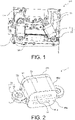
- FIG. 1 illustrates a power converter 100 according to an embodiment of the present invention.
- the power converter 100 can be, as mentioned above, an inverter configured to convert a DC voltage into an AC voltage in order to drive the electric motor.
- the AC voltage may be a multiphase AC voltage, in particular a three-phase AC voltage.
- the power converter 100 comprises a housing 110, one or plural magnetic core devices 1, and an electronic board mounted on a bottom plate of the housing 110.
- the housing 110 is preferably made of a conductive material (e.g. such as AISi12(fe)) and may be manufactured by a die-casting process.
- the electronic board is preferably a printed circuit board (PCB).
- the at least one busbar 120 being a DC busbar, comprises a set of electrical conductors 121 (i.e. positive and negative terminals).
- the electrical conductors 121 are preferably in a plate shape.
- the power converter 100 comprises two identical magnetic core devices 1.
- one magnetic core device 1 is described in detail in the following text. The invention is nevertheless not limited to the number of the magnetic core devices 1.
- the housing 110 comprises a top cover, the bottom plate, sidewalls, and a main chamber defined by the bottom plate and the sidewalls.
- the main chamber is used for accommodating the electronic board and the magnetic core device(s) 1 of the power converter 100.
- Other elements of the power converter 100 such as an insulating board, a heat sink and some electronic components, are also be accommodated in the main chamber.
- Figures 2 and 3 illustrate, according to different perspectives, the magnetic core device 1 of the power converter 100 according to an embodiment of the present invention.
- Figure 4 illustrates a cross-section of the magnetic core device 1.
- the magnetic core device 1 comprises at least one fixation leg 7, and a body 51 comprising a magnetic core 3.
- the at least one fixation leg 7, extending from the body 51, is configured to firmly fixate the magnetic core device 1 to a target component such as the housing 110 of the power converter 100.
- the at least one fixation leg 7 and the body 51 are integrally formed as one-piece in order to enhance the robustness of the magnetic core device 1 and to improve the fixation effect.
- the at least one fixation leg 7 extends from at least one of the sidewalls 55a to 55d (e.g. "sidewalls 55c and 55d" in Figures 2 to 4 ) of the body 51.
- the at least one fixation leg 7 and the corresponding sidewall (55c or 55d) are integrally formed as one-piece.
- the at least one fixation leg 7 extends from the bottom (e.g. "54" in Figures 2 to 4 ) of the body 51.
- the at least one fixation leg 7 and the bottom of the body 51 are integrally formed as one-piece.
- the at least one fixation leg 7 will be described in detail in the following paragraphs.
- the magnetic core device 1 comprises at least one passage 61 configured to allow at least one electrical conductor (e.g. the electrical plate conductors 121 of the busbar(s) 120 of the power converter 100) to pass through.
- each of the passages 61 is a passage with two openings 61a respectively located at one of two opposite sidewalls 55a, 55b of the body 51, wherein the two openings 61a are opposite to each other.
- the electrical plate conductors 121 of the busbar(s) 120 can thus pass through the magnetic core device 1, via the openings 61a and the passages 61 of the magnetic core device 1.
- at least one of the passages 61 allows plural electrical plate conductors 121 of plural busbars 120 to pass through.
- the openings 61a and the at least one fixation leg 7 are not located at the same sidewall(s) of the body 51.
- the passage 61 presents preferably a shape complementary to the shape of the extrinsic component 121.
- the invention is not limited to the number and the shape of the passage(s) 61 of the magnetic core device 1.
- the magnetic core device 1 may further comprise at least one insulation layer 58 made of an insulating material, such as plastic.
- the at least one insulation layer 58 is configured to separate the magnetic core 3 and the at least one electrical conductor (121) which passes through the magnetic core 3 of the body 51.
- the magnetic core 3 is either a monoblock or is comprised of plural portions respectively made of a magnetic material which is, for example, one or any combination of a nanocrystalline material, a ferrite material, and an iron powder material.
- the magnetic core 3 can be made of magnetic materials different from the above-mentioned ones.
- the magnetic core 3 comprises two E-shaped portions 31, 32 and two passages 61, as illustrated in Figure 4 .
- a middle portion of the magnetic core 3 between the passages 61 can be a ferrite bar while the rest of the magnetic core 3 is made of a nanocrystalline material.
- the magnetic core 3 comprises two U-shaped portions and one passage 61.
- the invention is not limited to the types of the magnetic material or the shape of the portions of the magnetic core 3.
- the magnetic core device 1 comprises plural fixation legs 7 extending from two opposite sidewalls 55c and 55d of the body 51.
- the fixation legs 7 are integrally formed with the sidewalls 55c and 55d which are opposite to each other, which makes the attachment of the magnetic core device 1 to the target component (e.g. the housing 110) more stable.
- the fixation legs 7 are preferably located at a lower portion of the magnetic core device 1, as illustrated in Figure 4 . In other words, the fixation legs 7 are preferably closer to the bottom 54 than to the top 53 of the body 51.
- fixation leg 7 is described in detail in the following text.
- the invention is nevertheless not limited to the number of the fixation legs 7.
- the fixation leg 7 is configured to be fixed to a fixation point on the target component (e.g. the housing 110).
- the body 51 can thus be fixated to a predetermined position on the target component (e.g. the housing 110).
- the fixation leg 7 comprises a main fixation element 71 which corresponds to a first fixation element (not illustrated in figures) arranged at the fixation point of the target component 110.
- the main fixation element 71 comprises a main fixation hole 72 and preferably an insert 73 comprising a central hole corresponding to the fixation hole 72.
- the insert 73 is utilized as a compression limiter made of a metal material or of plastic, and is embedded in the fixation leg 7 by an overmolding process. Alternatively, the insert 73 is inserted into the fixation leg 7 after the molding process (e.g. knurled compression limiters).
- the first fixation element comprises, for example, a target fixation hole at the fixation point of the target component 110.
- a major fixation mechanism can be provided by driving a screw or a rivet into the main fixation hole 72 and the corresponding target fixation hole, so as to firmly fixate the fixation leg 7 to the target point of the target component 110.
- the fixation point allows to create an extra area to share the pressure caused by the mass of the magnetic core device 1, which prevents the magnetic core device 1 from being detached from the target component 110.
- the magnetic core device 1 comprises further a positioning module (not illustrated in figures) configured to position the body 51 to the predetermined position on the target component (e.g. the housing 110).
- the positioning module preferably comprises at least one of following means: hole(s), oblong(s) and pin(s).
- the magnetic core device 1 preferably comprises at least one auxiliary fastener 22.
- the at least one auxiliary fastener 22 is located on the bottom 54 and is adapted to engage with at least one interlocking fastener (not illustrated in figures) arranged on the target component 110.
- the at least one auxiliary fastener 22 together with the at least one interlocking fastener, provides an auxiliary fixation mechanism allowing to attach the magnetic core device 1 to the target component 110, for example by clipping or snapping.
- the at least one auxiliary fastener 22 is preferably made integrally with the body 51 as one-piece.
- the body 51 (illustrated in Figures 2 to 4 ) of the magnetic core device 1 is the magnetic core 3.
- the magnetic core 3 is preferably made of an iron powder material.
- the sidewalls 55a to 55d of the body 51 are sidewalls of the magnetic core 3.
- the openings 61a and passage(s) 61 of the magnetic core device 1 are openings and passages formed on/in the magnetic core 3.
- the at least one fixation leg 7 extends from at least one of the sidewalls of the magnetic core 3 and/or from the bottom of the magnetic core 3.
- the at least one fixation leg 7 and the magnetic core 3 are integrally formed as one-piece, and are thus made of a same magnetic material (e.g. the iron powder material).
- the body 51 comprises, in addition to the magnetic core 3, a holder 8 configured to at least partially accommodate the magnetic core 3.
- the holder 8 is preferably made of an insulating material, such as plastic.
- the at least one fixation leg 7 extends from the holder 8 and is integrally formed with the holder 8 as one-piece. In this case, the at least one fixation leg 7 and the holder 8 are made of a same insulating material.
- the holder 8 being in the shape of a shallow-plate with a raised edge, comprises a support plate and the raised edge.
- the support plate together with the raised edge is configured to hold (i.e. to partially accommodate) the magnetic core 3.
- the magnetic core device 1 comprises further a core fixation means configured so that the magnetic core 3 is partially housed in the holder 8 but is still firmly attached to the support plate of the holder 8.
- the holder 8 does not have sidewalls.
- the sidewalls 55a to 55d of the body 51 are sidewalls of the magnetic core 3.
- the openings 61a and passage(s) 61 of the magnetic core device 1 are openings and passages formed on/in the magnetic core 3.
- the one or plural fixation legs 7 extend from the support plate, or from a joint of the support plate and the raised edge of the holder 8.
- the fixation leg(s) 7 and the support plate of the holder 8 are integrally formed as one-piece, and are thus made of a same insulating material.
- the holder 8 of the body 51 (illustrated in Figures 2 to 4 ) comprises a core chamber configured to entirely accommodate the magnetic core 3.
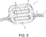
- Figure 5 illustrates a cross-section of the holder 8 according to an embodiment of the present invention.
- the inner volume of the core chamber is substantially equal to that of the magnetic core 3.
- the sidewalls 55a to 55d, the top 53 and the bottom 54 of the body 51 are sidewalls, a top wall and a sidewall of the holder 8.
- the openings 61a and passage(s) 61 of the magnetic core device 1 are respectively formed on the sidewalls and inside the holder 8, and respectively correspond to openings and passages formed in the magnetic core 3 housed in the core chamber of the holder 8.
- the at least one insulation layer 58 is preferably made integrally with the holder 8 as one-piece. Alternatively, the at least one insulation layer 58 is a separate element inserted into the holder 8.
- the at least one fixation leg 7 extends from at least one of the sidewalls of the holder 8 and/or from the bottom of the holder 8.
- the fixation legs 7 extend from the two opposite sidewalls of the holder 8, and are preferably located at a lower portion of the holder 8. In other words, the fixation legs 7 are preferably closer to the bottom than to the top of the holder 8.
- the one or plural fixation legs 7 and the sidewall(s) and/or the bottom of the holder where the one or plural fixation legs 7 are located are integrally formed as one-piece and are thus made of a same insulating material.
- the core chamber of the holder 8 comprises a chamber opening via which the magnetic core 3 is placed into the core chamber during a manufacturing process of the magnetic core device 1.
- the E-shaped portions 31, 32 are placed via the chamber opening into the core chamber.
- the holder 8 comprises a holder cap configured to close the chamber opening so as to seal the core chamber.
- the holder cap is preferably one of the sidewalls (e.g. sidewall 55b) or the top wall of the holder 8.
- the opening(s) 61a may also be located at the holder cap 55b.
- the rest of the holder 8 is integrally formed as one-piece.
- the holder cap 55b is different from the sidewalls 55c, 55d where the one or plural fixation legs 7 are located. Therefore, the existence of the fixation leg(s) 7 would not complicate an assembly step of placing the magnetic core 3 into the core chamber of the holder 8.
- the magnetic core 3 is formed together with the holder 8 by using a suitable mold in a (over)molding process.
- the holder 8 and the fixation leg(s) 7 extending from the holder 8, are integrally formed as one-piece without neither a chamber opening as mentioned above, nor a separate piece such as the holder cap.
- the invention allows to fixate the magnetic core device to the housing of the power converter without a fixation on the whole busbar.
- the invention uses the fixation legs integrally formed with the magnetic core device, which allows to considerably improve the fixation effect, especially in the uncontrolled or unexpected circumstances such as vibrations, impacts and/or high temperatures.
- the invention allows thus to improve the robustness of the magnetic core device and the power converter.
- no more glue is required for assembly, which simplifies the assembly process and reduces the manufacturing cost.
Landscapes
- Engineering & Computer Science (AREA)
- Power Engineering (AREA)
- Microelectronics & Electronic Packaging (AREA)
- Coils Or Transformers For Communication (AREA)
- Dc-Dc Converters (AREA)
- Inverter Devices (AREA)
Abstract
The invention concerns a magnetic core device (1) to be used in a power converter (100), comprising at least one fixation leg (7), and a body (51) comprising a magnetic core (3). The at least one fixation leg (7) extends from the body (51), and is configured to firmly fixate the magnetic core device (1) to a target component (110) such as a housing (110) of the power converter (100). The at least one fixation leg (7) and the body (51) are integrally formed as one-piece.
Description
- The present invention concerns a magnetic core device and a power converter.
- Power converters of an electric or a hybrid electric vehicle, are designed to convert an input voltage into an output voltage to be fed to the electric drive or other electric equipment of the vehicle.
- As it is known, an electric or a hybrid electric vehicle comprises an electric drive comprised of an electric motor and an inverter which converts a direct current (DC) voltage into an alternative current (AC) voltage so as to drive the electric motor. In addition to the inverter, the electric or hybrid electric vehicle comprises other power converters such as an on-board charger connected to an AC electrical network and charging thus electricity into a battery of the vehicle, or a DC/DC converter.
- A power converter comprises one or several magnetic core devices which are housed in a housing of the power converter and are fixed to said housing. The magnetic core devices can be utilized to prevent or limit the unwanted effects such as electromagnetic interference (EMI) of elements of the power converter.
- In general, several fixation mechanisms can be used. For example, a magnetic core device is attached to an inner surface of the housing with glue, by snapping or by clipping. However, when the power converter experiences a vibration, an uncontrolled impact and/or an unexpectedly high temperature, the above-mentioned fixation mechanisms cannot ensure that the magnetic core device is still properly fixed to its own predetermined position, especially when the magnetic core device is heavy. This would result in a decrease in the performance or even a malfunction of the magnetic core device and/or of the whole power converter. In addition, the use of glue increases the manufacturing cost of the power converter.
- Therefore, the main objective of the present invention is to provide a fixation mechanism which allows to improve the robustness of the magnetic core device and the power converter while reducing the manufacturing cost.
- The present invention concerns a magnetic core device to be used in a power converter, comprising at least one fixation leg, and a body comprising a magnetic core. The at least one fixation leg extends from the body, and is configured to firmly fixate the magnetic core device to a target component such as a housing of the power converter. The at least one fixation leg and the body are integrally formed as one-piece, in order to enhance the robustness of the magnetic core device and to improve the fixation effect.
- Therefore, the present invention allows to considerably improve the fixation effect, especially in the uncontrolled or unexpected circumstances such as vibrations, impacts and/or high temperatures. The invention allows thus to improve the robustness of the magnetic core device and the power converter. In addition, no more glue is required for assembly, which simplifies the assembly process and reduces the manufacturing cost.
- According to an embodiment, the at least one fixation leg extends from at least one of sidewalls of the body and/or from the bottom of the body of the magnetic core device.
- According to an embodiment, the magnetic core device comprising further at least one passage comprising openings located at two opposite sidewalls of the body, the at least one passage being configured to allow at least one electrical conductor to pass through. The at least one electrical conductor can be plural electrical plate conductors of busbar(s) of the power converter.
- Preferably, the at least one fixation leg and the opening(s) are not located at a same sidewall of the body.
- According to an embodiment, the at least one fixation leg comprises a main fixation hole corresponding to a target fixation hole located at a fixation point of the target component, so that a major fixation mechanism can be provided by driving a screw or a rivet into the main fixation hole and the target fixation hole, so as to firmly fixate the at least one fixation leg to the target point of the target component. The body of the magnetic core device can thus be fixated to a predetermined position on the target component (e.g. the housing of the power converter).
- According to an embodiment, the at least one fixation leg comprises an insert comprising a central hole corresponding to the fixation hole. The insert, being embedded in the at least one fixation leg, is utilized as a compression limiter made of a metal material or of plastic.
- Moreover, in addition to a surface of the target component in contact with the bottom of the magnetic core device, the fixation point allows to create an extra area to share the pressure caused by the mass of the magnetic core device, which prevents the magnetic core device from being detached from the target component.
- According to an embodiment, the magnetic core device comprises at least one auxiliary fastener being located on the bottom wall of the housing and being adapted to engage with at least one interlocking fastener arranged on the target component. Such an auxiliary fixation mechanism allows to attach the magnetic core device to the target component, for example by clipping or snapping.
- According to an embodiment, the at least one auxiliary fastener is made integrally with the body as one-piece.
- According to a preferable embodiment, the magnetic core device comprises plural fixation legs extending from two opposite sidewalls of the body. The fixation legs are integrally formed with the two opposite sidewalls, which makes the attachment of the magnetic core device to the target component more stable.
- According to an embodiment, the magnetic core device comprises further a positioning module configured to position the magnetic core device to the predetermined position on the target component (e.g. the housing of the power converter). The positioning module preferably comprises at least one of following means: hole(s), oblong(s) and/or pin(s).
- According to an embodiment, the body of the magnetic core device comprises a holder configured to at least partially accommodate the magnetic core, wherein the at least one fixation leg extends from the holder and is integrally formed with the holder as one-piece.
- According to an embodiment, the sidewalls of the body are sidewalls of the holder which define a core chamber configured to accommodate the magnetic core.
- According to an embodiment, the holder comprises a holder cap configured to close a chamber opening of the core chamber. Preferably, the holder cap is different from the at least one sidewall where the at least one fixation leg is located, so that the existence of the fixation leg(s) would not complicate an assembly step of placing the magnetic core into the core chamber.
- According to an embodiment, the holder is in the shape of a shallow-plate with a raised edge, and is configured to hold the magnetic core.
- According to a preferred embodiment, the holder is made of an insulating material.
- According to an embodiment, the magnetic core is made of one or any combination of a nanocrystalline material, a ferrite material and an iron powder material.
- According to an embodiment, the magnetic core comprises two E-shaped portions or two U-shaped portions.
- The present invention also concerns a power converter comprising a housing and the above-mentioned magnetic core device accommodated in the housing. The magnetic core device comprises at least one fixation leg, and a body comprising a magnetic core. The least one fixation leg, being configured to firmly fixate the magnetic core device to the housing, extends from the body and is integrally formed with the body as one-piece.
- The power converter according to the invention may be an inverter which converts a DC voltage into an AC voltage so as to drive an electric motor of an electric drive of an electric vehicle or of a hybrid electric vehicle. The AC voltage may be a multiphase AC voltage, in particular a three-phase AC voltage. Alternatively, the power converter may be an on-board charger or a DC/DC converter of the electric vehicle or the hybrid electric vehicle.
- A further aspect of the invention is an electric drive comprising an electric motor and the inverter as described above configured to convert a DC voltage into an AC voltage in order to drive the electric motor.
- Another aspect of the invention is an electric vehicle or a hybrid electric vehicle, comprising the electric drive configured to drive the electric vehicle or a hybrid electric vehicle.
- Although embodiments have been described with reference to a number of illustrative embodiments thereof, it should be understood that other modifications and embodiments can be derived by those skilled in the art that will fall within the scope of the principles of this disclosure.
- These and other objects, features, aspects and advantages of the present invention will become apparent to those skilled in the art from the following detailed description, which, taken in conjunction with the annexed drawings, discloses preferred embodiments of the present invention.
- The invention will be better understood on reading the description that follows, and by referring to the appended drawings given as non-limiting examples, in which identical references are given to similar objects and in which:
-
Figure 1 illustrates a power converter according to an embodiment of the present invention; -
Figures 2 and3 illustrate, according to different perspectives, a magnetic core device of the power converter, the magnetic core device comprising extension legs according to an embodiment of the present invention; -
Figure 4 illustrates a cross-section of the magnetic core device according to an embodiment of the present invention; -
Figure 5 illustrates a cross-section of a holder that the magnetic core device may have according to an embodiment of the present invention. - Several embodiments of the present invention will be detailed hereafter with reference to the drawings. It will be apparent to those skilled in the art from this present disclosure that the following description of these embodiments of the present invention are provided for illustration only and not for the purpose of limiting the invention as defined by the appended claims and their equivalents.
- The invention relates to an electric vehicle or a hybrid electric vehicle comprising wheels and an electric drive configured to drive, at least indirectly, at least one of the wheels of the vehicle. The electric drive comprises an electric motor and an inverter as a power converter, the inverter being configured to drive the electric motor by means of an AC voltage generated by the inverter. The power converter can be, alternatively, an on-board charger or a DC/DC converter of the electric vehicle or hybrid electric vehicle.
-
Figure 1 illustrates apower converter 100 according to an embodiment of the present invention. Thepower converter 100 can be, as mentioned above, an inverter configured to convert a DC voltage into an AC voltage in order to drive the electric motor. The AC voltage may be a multiphase AC voltage, in particular a three-phase AC voltage. - The
power converter 100 comprises ahousing 110, one or pluralmagnetic core devices 1, and an electronic board mounted on a bottom plate of thehousing 110. Thehousing 110 is preferably made of a conductive material (e.g. such as AISi12(fe)) and may be manufactured by a die-casting process. The electronic board is preferably a printed circuit board (PCB). The at least onebusbar 120, being a DC busbar, comprises a set of electrical conductors 121 (i.e. positive and negative terminals). Theelectrical conductors 121 are preferably in a plate shape. In the present embodiment thepower converter 100 comprises two identicalmagnetic core devices 1. For ease of illustration, onemagnetic core device 1 is described in detail in the following text. The invention is nevertheless not limited to the number of themagnetic core devices 1. - According to the present embodiment, the
housing 110 comprises a top cover, the bottom plate, sidewalls, and a main chamber defined by the bottom plate and the sidewalls. The main chamber is used for accommodating the electronic board and the magnetic core device(s) 1 of thepower converter 100. Other elements of thepower converter 100, such as an insulating board, a heat sink and some electronic components, are also be accommodated in the main chamber. -
Figures 2 and3 illustrate, according to different perspectives, themagnetic core device 1 of thepower converter 100 according to an embodiment of the present invention.Figure 4 illustrates a cross-section of themagnetic core device 1. Themagnetic core device 1 comprises at least onefixation leg 7, and abody 51 comprising a magnetic core 3. The magnetic core 3, acting as an inductance to filter either common mode or differential mode currents or a combination of both, is utilized to prevent or limit the unwanted effects such as EMI or even physical damage of elements of thepower converter 100. - The at least one
fixation leg 7, extending from thebody 51, is configured to firmly fixate themagnetic core device 1 to a target component such as thehousing 110 of thepower converter 100. The at least onefixation leg 7 and thebody 51 are integrally formed as one-piece in order to enhance the robustness of themagnetic core device 1 and to improve the fixation effect. - According to an embodiment, the at least one
fixation leg 7 extends from at least one of thesidewalls 55a to 55d (e.g. "sidewalls Figures 2 to 4 ) of thebody 51. The at least onefixation leg 7 and the corresponding sidewall (55c or 55d) are integrally formed as one-piece. According to an alternative embodiment (not illustrated in figures), the at least onefixation leg 7 extends from the bottom (e.g. "54" inFigures 2 to 4 ) of thebody 51. The at least onefixation leg 7 and the bottom of thebody 51 are integrally formed as one-piece. The at least onefixation leg 7 will be described in detail in the following paragraphs. - The
magnetic core device 1 comprises at least onepassage 61 configured to allow at least one electrical conductor (e.g. theelectrical plate conductors 121 of the busbar(s) 120 of the power converter 100) to pass through. As illustrated inFigures 2 to 4 , each of thepassages 61 is a passage with twoopenings 61a respectively located at one of twoopposite sidewalls body 51, wherein the twoopenings 61a are opposite to each other. Theelectrical plate conductors 121 of the busbar(s) 120 can thus pass through themagnetic core device 1, via theopenings 61a and thepassages 61 of themagnetic core device 1. According to an embodiment, at least one of thepassages 61 allows pluralelectrical plate conductors 121 ofplural busbars 120 to pass through. - According to an embodiment, the
openings 61a and the at least onefixation leg 7 are not located at the same sidewall(s) of thebody 51. In addition, thepassage 61 presents preferably a shape complementary to the shape of theextrinsic component 121. The invention is not limited to the number and the shape of the passage(s) 61 of themagnetic core device 1. - The
magnetic core device 1 may further comprise at least oneinsulation layer 58 made of an insulating material, such as plastic. The at least oneinsulation layer 58 is configured to separate the magnetic core 3 and the at least one electrical conductor (121) which passes through the magnetic core 3 of thebody 51. - The magnetic core 3 is either a monoblock or is comprised of plural portions respectively made of a magnetic material which is, for example, one or any combination of a nanocrystalline material, a ferrite material, and an iron powder material. Alternatively, the magnetic core 3 can be made of magnetic materials different from the above-mentioned ones. According to a embodiment, the magnetic core 3 comprises two
E-shaped portions passages 61, as illustrated inFigure 4 . A middle portion of the magnetic core 3 between thepassages 61 can be a ferrite bar while the rest of the magnetic core 3 is made of a nanocrystalline material. Alternatively, the magnetic core 3 comprises two U-shaped portions and onepassage 61. The invention is not limited to the types of the magnetic material or the shape of the portions of the magnetic core 3. - According to a preferable embodiment, the
magnetic core device 1 comprisesplural fixation legs 7 extending from twoopposite sidewalls body 51. Thefixation legs 7 are integrally formed with the sidewalls 55c and 55d which are opposite to each other, which makes the attachment of themagnetic core device 1 to the target component (e.g. the housing 110) more stable. Thefixation legs 7 are preferably located at a lower portion of themagnetic core device 1, as illustrated inFigure 4 . In other words, thefixation legs 7 are preferably closer to the bottom 54 than to the top 53 of thebody 51. - For ease of illustration, one
fixation leg 7 is described in detail in the following text. The invention is nevertheless not limited to the number of thefixation legs 7. Thefixation leg 7 is configured to be fixed to a fixation point on the target component (e.g. the housing 110). Thebody 51 can thus be fixated to a predetermined position on the target component (e.g. the housing 110). Thefixation leg 7 comprises amain fixation element 71 which corresponds to a first fixation element (not illustrated in figures) arranged at the fixation point of thetarget component 110. According to the present embodiment, themain fixation element 71 comprises amain fixation hole 72 and preferably aninsert 73 comprising a central hole corresponding to thefixation hole 72. Theinsert 73 is utilized as a compression limiter made of a metal material or of plastic, and is embedded in thefixation leg 7 by an overmolding process. Alternatively, theinsert 73 is inserted into thefixation leg 7 after the molding process (e.g. knurled compression limiters). - The first fixation element comprises, for example, a target fixation hole at the fixation point of the
target component 110. A major fixation mechanism can be provided by driving a screw or a rivet into themain fixation hole 72 and the corresponding target fixation hole, so as to firmly fixate thefixation leg 7 to the target point of thetarget component 110. Moreover, in addition to a surface of thetarget component 110 in contact with the bottom of themagnetic core device 1, the fixation point allows to create an extra area to share the pressure caused by the mass of themagnetic core device 1, which prevents themagnetic core device 1 from being detached from thetarget component 110. - According to an embodiment, the
magnetic core device 1 comprises further a positioning module (not illustrated in figures) configured to position thebody 51 to the predetermined position on the target component (e.g. the housing 110). The positioning module preferably comprises at least one of following means: hole(s), oblong(s) and pin(s). - In addition, as illustrated in
Figures 3 and 4 , themagnetic core device 1 preferably comprises at least oneauxiliary fastener 22. The at least oneauxiliary fastener 22 is located on the bottom 54 and is adapted to engage with at least one interlocking fastener (not illustrated in figures) arranged on thetarget component 110. The at least oneauxiliary fastener 22 together with the at least one interlocking fastener, provides an auxiliary fixation mechanism allowing to attach themagnetic core device 1 to thetarget component 110, for example by clipping or snapping. The at least oneauxiliary fastener 22 is preferably made integrally with thebody 51 as one-piece. - According to an embodiment, the body 51 (illustrated in
Figures 2 to 4 ) of themagnetic core device 1 is the magnetic core 3. In this case, the magnetic core 3 is preferably made of an iron powder material. Thesidewalls 55a to 55d of thebody 51 are sidewalls of the magnetic core 3. Theopenings 61a and passage(s) 61 of themagnetic core device 1 are openings and passages formed on/in the magnetic core 3. The at least onefixation leg 7 extends from at least one of the sidewalls of the magnetic core 3 and/or from the bottom of the magnetic core 3. The at least onefixation leg 7 and the magnetic core 3 are integrally formed as one-piece, and are thus made of a same magnetic material (e.g. the iron powder material). - Alternatively, the
body 51 comprises, in addition to the magnetic core 3, aholder 8 configured to at least partially accommodate the magnetic core 3. Theholder 8 is preferably made of an insulating material, such as plastic. The at least onefixation leg 7 extends from theholder 8 and is integrally formed with theholder 8 as one-piece. In this case, the at least onefixation leg 7 and theholder 8 are made of a same insulating material. - According to an embodiment (not illustrated in figures), the
holder 8, being in the shape of a shallow-plate with a raised edge, comprises a support plate and the raised edge. The support plate together with the raised edge is configured to hold (i.e. to partially accommodate) the magnetic core 3. Themagnetic core device 1 comprises further a core fixation means configured so that the magnetic core 3 is partially housed in theholder 8 but is still firmly attached to the support plate of theholder 8. In this case, theholder 8 does not have sidewalls. Thesidewalls 55a to 55d of thebody 51 are sidewalls of the magnetic core 3. Theopenings 61a and passage(s) 61 of themagnetic core device 1 are openings and passages formed on/in the magnetic core 3. The one orplural fixation legs 7 extend from the support plate, or from a joint of the support plate and the raised edge of theholder 8. The fixation leg(s) 7 and the support plate of theholder 8 are integrally formed as one-piece, and are thus made of a same insulating material. - According to another embodiment, the
holder 8 of the body 51 (illustrated inFigures 2 to 4 ) comprises a core chamber configured to entirely accommodate the magnetic core 3.Figure 5 illustrates a cross-section of theholder 8 according to an embodiment of the present invention. The inner volume of the core chamber is substantially equal to that of the magnetic core 3. Thesidewalls 55a to 55d, the top 53 and the bottom 54 of thebody 51 are sidewalls, a top wall and a sidewall of theholder 8. Theopenings 61a and passage(s) 61 of themagnetic core device 1 are respectively formed on the sidewalls and inside theholder 8, and respectively correspond to openings and passages formed in the magnetic core 3 housed in the core chamber of theholder 8. Moreover, the at least oneinsulation layer 58 is preferably made integrally with theholder 8 as one-piece. Alternatively, the at least oneinsulation layer 58 is a separate element inserted into theholder 8. - The at least one
fixation leg 7 extends from at least one of the sidewalls of theholder 8 and/or from the bottom of theholder 8. For example, as illustrated inFigure 5 , thefixation legs 7 extend from the two opposite sidewalls of theholder 8, and are preferably located at a lower portion of theholder 8. In other words, thefixation legs 7 are preferably closer to the bottom than to the top of theholder 8. The one orplural fixation legs 7 and the sidewall(s) and/or the bottom of the holder where the one orplural fixation legs 7 are located, are integrally formed as one-piece and are thus made of a same insulating material. - According to an embodiment, the core chamber of the
holder 8 comprises a chamber opening via which the magnetic core 3 is placed into the core chamber during a manufacturing process of themagnetic core device 1. For example, theE-shaped portions holder 8 comprises a holder cap configured to close the chamber opening so as to seal the core chamber. The holder cap is preferably one of the sidewalls (e.g. sidewall 55b) or the top wall of theholder 8. Moreover, the opening(s) 61a may also be located at theholder cap 55b. - According to an embodiment, except the holder cap, the rest of the
holder 8 is integrally formed as one-piece. Moreover, theholder cap 55b is different from the sidewalls 55c, 55d where the one orplural fixation legs 7 are located. Therefore, the existence of the fixation leg(s) 7 would not complicate an assembly step of placing the magnetic core 3 into the core chamber of theholder 8. - According to an alternative embodiment, during another manufacturing process different from the above-mentioned one, the magnetic core 3 is formed together with the
holder 8 by using a suitable mold in a (over)molding process. Theholder 8 and the fixation leg(s) 7 extending from theholder 8, are integrally formed as one-piece without neither a chamber opening as mentioned above, nor a separate piece such as the holder cap. - The invention allows to fixate the magnetic core device to the housing of the power converter without a fixation on the whole busbar. Compared to the above-mentioned conventional fixation mechanisms such as an attachment with glue or merely by clipping/snapping, the invention uses the fixation legs integrally formed with the magnetic core device, which allows to considerably improve the fixation effect, especially in the uncontrolled or unexpected circumstances such as vibrations, impacts and/or high temperatures. The invention allows thus to improve the robustness of the magnetic core device and the power converter. In addition, no more glue is required for assembly, which simplifies the assembly process and reduces the manufacturing cost.
Claims (15)
- A magnetic core device (1), comprising:- a body (51) comprising a magnetic core (3); and- at least one fixation leg (7), which extends from the body (51) and is configured to firmly fixate the magnetic core device (1) to a target component (110), the at least one fixation leg (7) and the body (51) being integrally formed as one-piece.
- The magnetic core device (1) according to claim 1, wherein:- the at least one fixation leg (7) extends from at least one of sidewalls (55a to 55d) of the body (51) and/or from the bottom of the body (51), and/or- the magnetic core device (1) comprising further at least one passage (61) comprising openings (61a) located at two opposite sidewalls (55a to 55d) of the body (51), the at least one passage (61) being configured to allow at least one electrical conductor (121) to pass through.
- The magnetic core device (1) according to claim 2, wherein the at least one fixation leg (7) and the openings (61a) are not located at a same sidewall of the body (51).
- The magnetic core device (1) according to any one of the preceding claims, wherein the at least one fixation leg (7) comprises a main fixation hole (72) corresponding to a target fixation hole located at a fixation point of the target component (110), so that by driving a screw or a rivet into the main fixation hole (72) and the target fixation hole, the at least one fixation leg (7) is fixed to the target point of the target component (110).
- The magnetic core device (1) according to the preceding claim, wherein the at least one fixation leg (7) comprises an insert (73) comprising a central hole corresponding to the fixation hole (72); the insert (73) being embedded in the at least one fixation leg (7) and utilized as a compression limiter made of a metal material or of plastic.
- The magnetic core device (1) according to any one of the preceding claims, comprising at least one auxiliary fastener (22) being located on the bottom (54) of the body (51) and being adapted to engage, by clipping or snapping, with at least one interlocking fastener arranged on the target component (110).
- The magnetic core device (1) according to the preceding claim, wherein the at least one auxiliary fastener (22) is made integrally with the body (51) as one-piece.
- The magnetic core device (1) according to any one of the preceding claims, comprising plural fixation legs (7) extending from two opposite sidewalls (55c, 55d) of the body (51), the fixation legs (7) being integrally formed with the two opposite sidewalls (55c, 55d).
- The magnetic core device (1) according to any one of the preceding claims, wherein the body (51) comprises a holder (8) configured to at least partially accommodate the magnetic core (3), wherein the at least one fixation leg (7) extends from the holder (8) and is integrally formed with the holder (8) as one-piece.
- The magnetic core device (1) according to the preceding claim in combination with claim 2, wherein the sidewalls (55a to 55d) of the body (51) are sidewalls of the holder (8) which define a core chamber configured to accommodate the magnetic core (3).
- The magnetic core device (1) according to the preceding claim, wherein the holder (8) comprises a holder cap (55b) configured to close a chamber opening of the core chamber.
- The magnetic core device (1) according to the preceding claim, wherein the holder cap (55b) is different from the at least one sidewall (55c, 55d) where the at least one fixation leg (7) is located.
- The magnetic core device (1) according to claim 9, wherein the holder (8) is in the shape of a shallow-plate with a raised edge, and is configured to hold the magnetic core (3).
- The magnetic core device (1) according to any one of the preceding claims 9 to 13, wherein:- the holder (8) is made of an insulating material; and/or- the magnetic core (3) is made of one or any combination of a nanocrystalline material, a ferrite material, and an iron powder material, the magnetic core comprising two E-shaped portions (31, 32) or two U-shaped portions.
- A power converter (100), comprising:- a housing (110), configured to accommodate the magnetic core device (1); and- a magnetic core device (1) according to any one of claims 1 to 14, comprising a body (51), and at least one fixation leg (7) configured to firmly fixate the magnetic core device (1) to the housing (110), wherein the at least one fixation leg (7) extends from the body (51) and is integrally formed with the body (51) as one-piece.
Priority Applications (5)
| Application Number | Priority Date | Filing Date | Title |
|---|---|---|---|
| EP21182024.6A EP4113549A1 (en) | 2021-06-28 | 2021-06-28 | A magnetic core device and a power converter |
| JP2022103053A JP2023007503A (en) | 2021-06-28 | 2022-06-27 | Magnetic core device and power converter |
| US17/809,423 US20220415557A1 (en) | 2021-06-28 | 2022-06-28 | A magnetic core device and a power converter |
| CN202210747543.4A CN115602422A (en) | 2021-06-28 | 2022-06-28 | Magnetic core device and power converter |
| KR1020220078872A KR20230001550A (en) | 2021-06-28 | 2022-06-28 | A magnetic core device and a power converter |
Applications Claiming Priority (1)
| Application Number | Priority Date | Filing Date | Title |
|---|---|---|---|
| EP21182024.6A EP4113549A1 (en) | 2021-06-28 | 2021-06-28 | A magnetic core device and a power converter |
Publications (1)
| Publication Number | Publication Date |
|---|---|
| EP4113549A1 true EP4113549A1 (en) | 2023-01-04 |
Family
ID=76744598
Family Applications (1)
| Application Number | Title | Priority Date | Filing Date |
|---|---|---|---|
| EP21182024.6A Pending EP4113549A1 (en) | 2021-06-28 | 2021-06-28 | A magnetic core device and a power converter |
Country Status (5)
| Country | Link |
|---|---|
| US (1) | US20220415557A1 (en) |
| EP (1) | EP4113549A1 (en) |
| JP (1) | JP2023007503A (en) |
| KR (1) | KR20230001550A (en) |
| CN (1) | CN115602422A (en) |
Citations (7)
| Publication number | Priority date | Publication date | Assignee | Title |
|---|---|---|---|---|
| JPH1074631A (en) * | 1996-06-25 | 1998-03-17 | Hitachi Ferrite Denshi Kk | Magnetic core and zero-phase reactor |
| JP2014096538A (en) * | 2012-11-12 | 2014-05-22 | Kitagawa Ind Co Ltd | Composite ferrite core and noise current absorption tool |
| JP2014222974A (en) * | 2013-05-13 | 2014-11-27 | 本田技研工業株式会社 | Bus bar structure |
| DE102015205815A1 (en) * | 2015-03-31 | 2016-10-06 | Siemens Aktiengesellschaft | Fixing device for a jacket-wave filter, jacket-wave filter device with such a fixing device and motor vehicle with such a jacket shaft filter device |
| EP3089178A1 (en) * | 2015-04-28 | 2016-11-02 | Kitagawa Industries Co., Ltd. | Magnetic core |
| EP3312854A1 (en) * | 2015-06-19 | 2018-04-25 | Kitagawa Industries Co., Ltd. | Noise suppression member |
| DE102019116362A1 (en) * | 2019-06-17 | 2020-12-17 | Tdk Electronics Ag | Filter component and arrangement for fastening a filter component |
Family Cites Families (9)
| Publication number | Priority date | Publication date | Assignee | Title |
|---|---|---|---|---|
| JP3556172B2 (en) * | 2001-01-29 | 2004-08-18 | 北川工業株式会社 | Noise absorber and magnetic material holding case |
| TW534487U (en) * | 2001-02-23 | 2003-05-21 | Hon Hai Prec Ind Co Ltd | Filtering device for cable connector |
| US6584950B1 (en) * | 2002-05-29 | 2003-07-01 | Bayer Corporation | Oil pan |
| JP5499795B2 (en) * | 2010-03-15 | 2014-05-21 | 富士電機株式会社 | Case structure of EMC filter unit and inverter device |
| US10431369B2 (en) * | 2015-06-05 | 2019-10-01 | Tamura Corporation | Reactor |
| JP2019193466A (en) * | 2018-04-26 | 2019-10-31 | 株式会社オートネットワーク技術研究所 | Power conversion device |
| JP7062130B2 (en) * | 2019-03-11 | 2022-05-02 | 三菱電機株式会社 | Power converter |
| JP7613880B2 (en) * | 2020-10-23 | 2025-01-15 | 株式会社トーキン | Reactor |
| CN115020082B (en) * | 2021-03-04 | 2025-02-11 | 台达电子企业管理(上海)有限公司 | Power modules and multi-winding inductors |
-
2021
- 2021-06-28 EP EP21182024.6A patent/EP4113549A1/en active Pending
-
2022
- 2022-06-27 JP JP2022103053A patent/JP2023007503A/en active Pending
- 2022-06-28 CN CN202210747543.4A patent/CN115602422A/en active Pending
- 2022-06-28 US US17/809,423 patent/US20220415557A1/en active Pending
- 2022-06-28 KR KR1020220078872A patent/KR20230001550A/en not_active Ceased
Patent Citations (7)
| Publication number | Priority date | Publication date | Assignee | Title |
|---|---|---|---|---|
| JPH1074631A (en) * | 1996-06-25 | 1998-03-17 | Hitachi Ferrite Denshi Kk | Magnetic core and zero-phase reactor |
| JP2014096538A (en) * | 2012-11-12 | 2014-05-22 | Kitagawa Ind Co Ltd | Composite ferrite core and noise current absorption tool |
| JP2014222974A (en) * | 2013-05-13 | 2014-11-27 | 本田技研工業株式会社 | Bus bar structure |
| DE102015205815A1 (en) * | 2015-03-31 | 2016-10-06 | Siemens Aktiengesellschaft | Fixing device for a jacket-wave filter, jacket-wave filter device with such a fixing device and motor vehicle with such a jacket shaft filter device |
| EP3089178A1 (en) * | 2015-04-28 | 2016-11-02 | Kitagawa Industries Co., Ltd. | Magnetic core |
| EP3312854A1 (en) * | 2015-06-19 | 2018-04-25 | Kitagawa Industries Co., Ltd. | Noise suppression member |
| DE102019116362A1 (en) * | 2019-06-17 | 2020-12-17 | Tdk Electronics Ag | Filter component and arrangement for fastening a filter component |
Also Published As
| Publication number | Publication date |
|---|---|
| KR20230001550A (en) | 2023-01-04 |
| CN115602422A (en) | 2023-01-13 |
| US20220415557A1 (en) | 2022-12-29 |
| JP2023007503A (en) | 2023-01-18 |
Similar Documents
| Publication | Publication Date | Title |
|---|---|---|
| EP2830073B1 (en) | Power conversion apparatus | |
| US8953335B2 (en) | Semiconductor control device | |
| CN105101744A (en) | Coldplate with Integrated Electrical Components for Cooling Thereof | |
| US20230032114A1 (en) | Electrical connection structure | |
| CN111095769A (en) | Power conversion device | |
| US10784610B2 (en) | Conductive connection structure, multifunctional high-voltage connector and battery product | |
| EP3691094A1 (en) | Controller and motor assembly comprising same | |
| US20150287511A1 (en) | Connector device | |
| CN113937541B (en) | High voltage junction box line tray | |
| EP4113549A1 (en) | A magnetic core device and a power converter | |
| US11929687B2 (en) | Power converter | |
| WO2021057951A1 (en) | Electronic device and heat sink of the electronic device | |
| US6297981B1 (en) | Compact electrical device, especially a switched-mode power supply | |
| WO2021057950A1 (en) | Electronic device and fixing module thereof for fixing element | |
| US7063570B1 (en) | Electrical connector and component packaging assembly | |
| EP4114155A1 (en) | Busbar assembly comprising a magnetic core device | |
| US20240237217A9 (en) | Circuit board having composite magnetic components mounted thereon | |
| CN216084749U (en) | Leakage protection moulded case circuit breaker | |
| KR20140004847A (en) | Bobbin structure provided with terminal block and magnetic body using the same | |
| KR102848070B1 (en) | Battery pack comprising high voltage wire assembly and manufacturing method of the battery pack | |
| US20230361548A1 (en) | Electrical junction box | |
| CN116745175A (en) | Maintaining means for maintaining at least one electrical wiring harness adjacent the battery tray | |
| CN223553671U (en) | Controller and vehicle | |
| CN221747108U (en) | A battery pack disconnect unit | |
| CN221315811U (en) | Controller assembly and vehicle |
Legal Events
| Date | Code | Title | Description |
|---|---|---|---|
| STAA | Information on the status of an ep patent application or granted ep patent |
Free format text: STATUS: EXAMINATION IS IN PROGRESS |
|
| PUAI | Public reference made under article 153(3) epc to a published international application that has entered the european phase |
Free format text: ORIGINAL CODE: 0009012 |
|
| 17P | Request for examination filed |
Effective date: 20210628 |
|
| AK | Designated contracting states |
Kind code of ref document: A1 Designated state(s): AL AT BE BG CH CY CZ DE DK EE ES FI FR GB GR HR HU IE IS IT LI LT LU LV MC MK MT NL NO PL PT RO RS SE SI SK SM TR |
|
| RAP1 | Party data changed (applicant data changed or rights of an application transferred) |
Owner name: VALEO ELECTRIFICATION |