EP4113543A1 - Cable - Google Patents
Cable Download PDFInfo
- Publication number
- EP4113543A1 EP4113543A1 EP21181948.7A EP21181948A EP4113543A1 EP 4113543 A1 EP4113543 A1 EP 4113543A1 EP 21181948 A EP21181948 A EP 21181948A EP 4113543 A1 EP4113543 A1 EP 4113543A1
- Authority
- EP
- European Patent Office
- Prior art keywords
- light
- cable
- emitting
- conductor
- strand
- Prior art date
- Legal status (The legal status is an assumption and is not a legal conclusion. Google has not performed a legal analysis and makes no representation as to the accuracy of the status listed.)
- Withdrawn
Links
- 239000004020 conductor Substances 0.000 claims abstract description 70
- 238000009413 insulation Methods 0.000 claims abstract description 17
- 239000000463 material Substances 0.000 claims description 5
- 239000000945 filler Substances 0.000 claims description 4
- 239000013307 optical fiber Substances 0.000 claims description 4
- 239000004809 Teflon Substances 0.000 claims description 2
- 229920006362 Teflon® Polymers 0.000 claims description 2
- 239000000654 additive Substances 0.000 claims description 2
- 230000000996 additive effect Effects 0.000 claims description 2
- 238000002604 ultrasonography Methods 0.000 claims description 2
- 238000004519 manufacturing process Methods 0.000 description 2
- RYGMFSIKBFXOCR-UHFFFAOYSA-N Copper Chemical compound [Cu] RYGMFSIKBFXOCR-UHFFFAOYSA-N 0.000 description 1
- 229910052802 copper Inorganic materials 0.000 description 1
- 239000010949 copper Substances 0.000 description 1
- 230000001419 dependent effect Effects 0.000 description 1
Images



Classifications
-
- H—ELECTRICITY
- H01—ELECTRIC ELEMENTS
- H01B—CABLES; CONDUCTORS; INSULATORS; SELECTION OF MATERIALS FOR THEIR CONDUCTIVE, INSULATING OR DIELECTRIC PROPERTIES
- H01B9/00—Power cables
- H01B9/005—Power cables including optical transmission elements
-
- A—HUMAN NECESSITIES
- A01—AGRICULTURE; FORESTRY; ANIMAL HUSBANDRY; HUNTING; TRAPPING; FISHING
- A01M—CATCHING, TRAPPING OR SCARING OF ANIMALS; APPARATUS FOR THE DESTRUCTION OF NOXIOUS ANIMALS OR NOXIOUS PLANTS
- A01M29/00—Scaring or repelling devices, e.g. bird-scaring apparatus
- A01M29/06—Scaring or repelling devices, e.g. bird-scaring apparatus using visual means, e.g. scarecrows, moving elements, specific shapes, patterns or the like
- A01M29/10—Scaring or repelling devices, e.g. bird-scaring apparatus using visual means, e.g. scarecrows, moving elements, specific shapes, patterns or the like using light sources, e.g. lasers or flashing lights
Definitions
- the present invention relates to a cable with bird protection.
- Cables are often installed and used outdoors, where they are free-hanging between power poles or masts. This poses a risk to birds that can fly into the cables because they are not visible, in particular during the night or other conditions with poor visibility.
- the problem of the present invention is to provide an improved cable that reduces the risk of collision for birds.
- the inventive solution shall be applicable for any cable structure that has been defined according to given requirements and specifications.
- Manufacturing processes and layer material used for conventional cables shall be applicable for manufacturing the cable.
- inventive solution shall be applicable to cables used in various conditions particularly outdoors, in particular to free-hanging cables suspended between power poles.
- the cable comprises
- the cable further comprises a light-emitting strand, suited to emit light, that is also enclosed by the outer sheath.
- the outer sheath is at least partially optically transparent to the light emitted by the light-emitting strand.
- the cable is hence better visible due to the light emitted by the light-emitting strand. Birds will therefore see the cable and not collide with it.
- the light-emitting strand comprises a first insulated conductor and a second insulated conductor.
- the first insulated conductor and the second insulated conductor are twisted together to form a twisted conductor pair.
- the light-emitting strand comprises several light-emitting units.
- the light-emitting units are equally spaced along the cable, particularly preferred with a distance of 0.5-5m between two light emitting units.
- the light-emitting strand and the at least one conductor are twisted along the long cable axis.
- the light-emission of the cable is hence directed in various radial directions, improving the visibility of the cable.
- the light-emitting units each comprise a light-emitting device which is electrically connected through an electrical connection to the first insulated conductor at an electrical contact point and which is electrically connected through an electrical connection to the second insulated conductor at an electrical contact point.
- An electrical resistance is preferably connected in series with the light-emitting device between the first insulated conductor and the second insulated conductor.
- the light-emitting units preferably emit violet visible light. In another embodiment, the light-emitting units emit ultraviolet light. Particularly preferred, the light-emitting units emit light at a wavelength between 350nm and 450nm. Further preferred, the light-emitting units emit light at different wavelengths. This improves the overall visibility of the cable.
- the light-emitting unit comprises in a preferred embodiment according to the present invention one or several light-emitting diodes.
- the cable comprises at least two light-emitting strands, each of which suited to emit light, that are both enclosed by the outer sheath.
- the cable further comprises an optical fibre and/or one or several fillers and/or an inner sheath. This improves the overall shape or roundness of the cable.
- the cable comprises several conductors, which are each surrounded by a conductor insulation layer and which are all enclosed within the outer sheath.
- the cable may comprise one or several sensors, such as daylight sensors, rain sensors or ultrasound sensors.
- the outer sheath is preferably made from an optically transparent PVC-based polymeric material.
- the optically transparent PVC-based polymeric material preferably comprises a UV-stabilizing additive. The cable lifetime is hence improved.
- the light-emitting units are preferably electrically connected in parallel between the first insulated conductor and the second insulated conductor.
- the light-emitting strand is preferably wrapped in at least one layer of transparent Teflon tape.
- the light-emitting strand can hence easily be fabricated and then integrated in any cable design.
- the conductors are preferably made of stranded or bunched copper conductors.
- An inventive cable is preferably part of an equally inventive bird protection system.
- the bird protection system preferably comprises an inventive cable and a power unit that is suited to power the light-emitting units of the light-emitting strand through a connecting cable.
- Fig. 1 schematically shows a cross-sectional view of a first embodiment of an inventive cable 10.
- the cable comprises a conductor 1A which is electrically insulated by a surrounding conductor insulation layer 2A.
- the cable further comprises a light-emitting strand 5.
- the light-emitting strand 5 and the conductor 1A, respectively the conductor insulation layer 2A, are embedded in an inner sheath.
- the conductor 1A, the conductor insulation layer 2A, the light-emitting strand 5 and the inner sheath 9 are enclosed by an outer sheath 4.
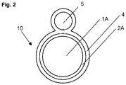
- Fig. 2 schematically depicts a cross-sectional view of a second embodiment of an inventive cable 10.
- the cable comprises a conductor 1A which is electrically insulated by a surrounding conductor insulation layer 2A.
- the cable further comprises a light-emitting strand 5.
- the conductor 1A, the conductor insulation layer 2A and the light-emitting strand 5 are enclosed and bound together by an outer sheath 4.
- Fig. 3 shows a cross-sectional view of a fifth embodiment of an inventive cable 10.
- the cable comprises three conductors 1A, 1B, 1C, each electrically insulated by a conductor insulation layer 2A, 2B, 2C.
- the cable further comprises an optical fibre 6 and a filler 3.
- the cable comprises two light-emitting strands 5, 5'. All aforementioned components are integrated in an inner sheath 9 which is enclosed in an outer sheath 4.
- Fig. 4a shows a preferred embodiment of a light-emitting strand 5 for an inventive cable.
- the light-emitting strand 5 comprises a first insulated conductor 51 and a second insulated conductor 52 that are twisted together.
- several light-emitting units 53, 53',... are electrically connected between the first insulated conductor 51 and the second insulated conductor 52.
- Fig. 4b shows a detailed view of area A highlighted in Fig. 4a .
- a light-emitting unit 53 is electrically connected between the first insulated conductor 51 and the second insulated conductor 52.
- the light-emitting unit 53 comprises an electrical resistance 531 and a light-emitting device 532.
- the light-emitting unit 53 is electrically connected to the first insulated conductor 51 through an electrical connection 534.
- the electrical connection 534 is electrically contacting the first insulated conductor 51 at an electric contact point 511.
- the electric contact point 511 preferably is a short cable portion that has been stripped from the insulation layer.
- the light-emitting unit 53 is electrically connected to the second insulated conductor 52 through an electrical connection 533.
- the electrical connection 533 is electrically contacting the second insulated conductor 52 at an electric contact point 521.
- the electric contact point 521 preferably is a short cable portion that has been stripped from the insulation layer.
- Fig. 5 shows an inventive bird protection system 100 for an inventive cable 10 suspended between two power poles 80, 80'.
- the cable 10 is free-hanging between the poles 80, 80' at a height at which birds fly.
- the cable protection system 100 comprises a power unit 60 that is connected through a connecting cable 90 to the cable 10.
- the power unit 60 is used to power the light-emitting strand of the cable 10.
Landscapes
- Life Sciences & Earth Sciences (AREA)
- Physics & Mathematics (AREA)
- Optics & Photonics (AREA)
- Birds (AREA)
- Engineering & Computer Science (AREA)
- Insects & Arthropods (AREA)
- Pest Control & Pesticides (AREA)
- Wood Science & Technology (AREA)
- Zoology (AREA)
- Environmental Sciences (AREA)
- Insulated Conductors (AREA)
Abstract
A cable (10) comprising:- at least one conductor (1A, 1B, 1C,...);- at least one conductor insulation layer (2A, 2B, 2C,...) formed around and enclosing said at least one conductor (1A, 1B, 1C,...);- an outer sheath (4) enclosing said conductor insulation layer (2A, 2B, 2C,...) and said at least one conductor (1A, 1B, 1C,...).According to the invention, the cable (10) further comprises a light-emitting strand (5), suited to emit light, that is enclosed by said outer sheath (4) and that the outer sheath (4) is at least partially optically transparent to the light emitted by the light-emitting strand (5).
Description
- The present invention relates to a cable with bird protection.
- A variety of cables for different types of applications is known from the state of the art.
- Cables are often installed and used outdoors, where they are free-hanging between power poles or masts. This poses a risk to birds that can fly into the cables because they are not visible, in particular during the night or other conditions with poor visibility.
- The problem of the present invention is to provide an improved cable that reduces the risk of collision for birds.
- The inventive solution shall be applicable for any cable structure that has been defined according to given requirements and specifications.
- Manufacturing processes and layer material used for conventional cables shall be applicable for manufacturing the cable.
- Further, the inventive solution shall be applicable to cables used in various conditions particularly outdoors, in particular to free-hanging cables suspended between power poles.
- The problem is solved by a cable according to claim 1 and a bird protection system according to claim 14. Further preferred embodiments of the cable are defined in dependent claims.
- The cable comprises
- at least one conductor;
- at least one conductor insulation layer formed around and enclosing the at least one conductor;
- an outer sheath enclosing the conductor insulation layer and the at least one conductor.
- According to the invention, the cable further comprises a light-emitting strand, suited to emit light, that is also enclosed by the outer sheath. The outer sheath is at least partially optically transparent to the light emitted by the light-emitting strand. The cable is hence better visible due to the light emitted by the light-emitting strand. Birds will therefore see the cable and not collide with it.
- In a preferred embodiment, the light-emitting strand comprises a first insulated conductor and a second insulated conductor.
- Preferably, the first insulated conductor and the second insulated conductor are twisted together to form a twisted conductor pair.
- In a particularly preferred embodiment of the present invention, the light-emitting strand comprises several light-emitting units. Preferably, the light-emitting units are equally spaced along the cable, particularly preferred with a distance of 0.5-5m between two light emitting units.
- In preferred embodiments, the light-emitting strand and the at least one conductor are twisted along the long cable axis. The light-emission of the cable is hence directed in various radial directions, improving the visibility of the cable.
- In further preferred embodiments, the light-emitting units each comprise a light-emitting device which is electrically connected through an electrical connection to the first insulated conductor at an electrical contact point and which is electrically connected through an electrical connection to the second insulated conductor at an electrical contact point. An electrical resistance is preferably connected in series with the light-emitting device between the first insulated conductor and the second insulated conductor.
- The light-emitting units preferably emit violet visible light. In another embodiment, the light-emitting units emit ultraviolet light. Particularly preferred, the light-emitting units emit light at a wavelength between 350nm and 450nm. Further preferred, the light-emitting units emit light at different wavelengths. This improves the overall visibility of the cable.
- The light-emitting unit comprises in a preferred embodiment according to the present invention one or several light-emitting diodes.
- In a further embodiment according to the invention, the cable comprises at least two light-emitting strands, each of which suited to emit light, that are both enclosed by the outer sheath.
- In another embodiment according to the invention, the cable further comprises an optical fibre and/or one or several fillers and/or an inner sheath. This improves the overall shape or roundness of the cable.
- Preferably, the cable comprises several conductors, which are each surrounded by a conductor insulation layer and which are all enclosed within the outer sheath.
- The cable may comprise one or several sensors, such as daylight sensors, rain sensors or ultrasound sensors.
- The outer sheath is preferably made from an optically transparent PVC-based polymeric material. The optically transparent PVC-based polymeric material preferably comprises a UV-stabilizing additive. The cable lifetime is hence improved.
- The light-emitting units are preferably electrically connected in parallel between the first insulated conductor and the second insulated conductor. The light-emitting strand is preferably wrapped in at least one layer of transparent Teflon tape. The light-emitting strand can hence easily be fabricated and then integrated in any cable design.
- The conductors are preferably made of stranded or bunched copper conductors.
- An inventive cable is preferably part of an equally inventive bird protection system. The bird protection system preferably comprises an inventive cable and a power unit that is suited to power the light-emitting units of the light-emitting strand through a connecting cable.
- The present invention will be further described by way of example, with reference to the accompanying drawings, wherein:
- Fig. 1
- shows a cross-sectional view of a first embodiment of an
inventive cable 10; - Fig. 2
- shows a cross-sectional view of a second embodiment of an
inventive cable 10; - Fig. 3
- shows a cross-sectional view of a third embodiment of an
inventive cable 10; - Fig. 4a
- shows a preferred embodiment of a light-emitting
strand 5 for an inventive cable; - Fig. 4b
- shows a detailed view of area A highlighted in
Fig. 4a ; and - Fig. 5
- shows an inventive
bird protection system 100 for aninventive cable 10 suspended between twopower poles 80, 80'; -
Fig. 1 schematically shows a cross-sectional view of a first embodiment of aninventive cable 10. The cable comprises aconductor 1A which is electrically insulated by a surroundingconductor insulation layer 2A. The cable further comprises a light-emittingstrand 5. The light-emittingstrand 5 and theconductor 1A, respectively theconductor insulation layer 2A, are embedded in an inner sheath. Theconductor 1A, theconductor insulation layer 2A, the light-emittingstrand 5 and theinner sheath 9 are enclosed by anouter sheath 4. -
Fig. 2 schematically depicts a cross-sectional view of a second embodiment of aninventive cable 10. The cable comprises aconductor 1A which is electrically insulated by a surroundingconductor insulation layer 2A. The cable further comprises a light-emittingstrand 5. Theconductor 1A, theconductor insulation layer 2A and the light-emittingstrand 5 are enclosed and bound together by anouter sheath 4. -
Fig. 3 shows a cross-sectional view of a fifth embodiment of aninventive cable 10. The cable comprises threeconductors conductor insulation layer optical fibre 6 and afiller 3. The cable comprises two light-emittingstrands 5, 5'. All aforementioned components are integrated in aninner sheath 9 which is enclosed in anouter sheath 4. -
Fig. 4a shows a preferred embodiment of a light-emittingstrand 5 for an inventive cable. The light-emittingstrand 5 comprises a firstinsulated conductor 51 and a secondinsulated conductor 52 that are twisted together. Along the light-emittingstrand 5, several light-emittingunits 53, 53',... are electrically connected between the firstinsulated conductor 51 and the secondinsulated conductor 52. -
Fig. 4b shows a detailed view of area A highlighted inFig. 4a . A light-emittingunit 53 is electrically connected between the firstinsulated conductor 51 and the secondinsulated conductor 52. The light-emittingunit 53 comprises anelectrical resistance 531 and a light-emittingdevice 532. The light-emittingunit 53 is electrically connected to the firstinsulated conductor 51 through anelectrical connection 534. Theelectrical connection 534 is electrically contacting the firstinsulated conductor 51 at anelectric contact point 511. Theelectric contact point 511 preferably is a short cable portion that has been stripped from the insulation layer. The light-emittingunit 53 is electrically connected to the secondinsulated conductor 52 through anelectrical connection 533. Theelectrical connection 533 is electrically contacting the secondinsulated conductor 52 at anelectric contact point 521. Theelectric contact point 521 preferably is a short cable portion that has been stripped from the insulation layer. -
Fig. 5 shows an inventivebird protection system 100 for aninventive cable 10 suspended between twopower poles 80, 80'. Thecable 10 is free-hanging between thepoles 80, 80' at a height at which birds fly. Thecable protection system 100 comprises a power unit 60 that is connected through a connectingcable 90 to thecable 10. The power unit 60 is used to power the light-emitting strand of thecable 10. - The embodiments presented in the figures and description are only non-limiting illustrative examples of embodiments according to the invention. Further embodiments according to the invention can be realized by combining technical features from any of the embodiments shown as well as with technical features that are commonly used in cable design.
-
- 1A, 1B, 1C,...
- conductor
- 2A, 2B, 2C,...
- conductor insulation layer
- 3
- filler
- 4
- outer sheath
- 5, 5'
- light-emitting strand
- 51
- first insulated conductor
- 511
- electrical contact point
- 52
- second insulated conductor
- 521
- electrical contact point
- 53, 53'
- light-emitting unit
- 531
- electrical resistance
- 532
- light-emitting device
- 533
- electrical connection
- 534
- electrical connection
- 6
- optical fibre
- 9
- inner sheath
- 10
- cable
- 70
- power unit
- 80, 80'
- power poles
- 90
- connecting cable
- 100
- bird protection system
Claims (15)
- A cable (10) comprising:- at least one conductor (1A, 1B, 1C,...);- at least one conductor insulation layer (2A, 2B, 2C,...) formed around and enclosing said at least one conductor (1A, 1B, 1C,...);- an outer sheath (4) enclosing said conductor insulation layer (2A, 2B, 2C,...) and said at least one conductor (1A, 1B, 1C,...);characterized in that;
the cable (10) further comprises a light-emitting strand (5), suited to emit light, that is enclosed by said outer sheath (4) and that the outer sheath (4) is at least partially optically transparent to the light emitted by the light-emitting strand (5). - A cable (10) according to claim 1, wherein the light-emitting strand (5) comprises a first insulated conductor (51) and a second insulated conductor (52), the first insulated conductor (51) and the second insulated conductor (52) being preferably twisted together.
- A cable (10) according to claim 1 or 2, wherein the light-emitting strand (5) comprises several light-emitting units (53, 53',...), which are preferably equally spaced along the cable, preferably with a distance of 0.5-5m between two light emitting units (53, 53'...).
- A cable (10) according to claim 1, 2 or 3, wherein the light-emitting strand (5) and the at least one conductor (1A, 1B, 1C,...) are twisted along the long cable axis.
- A cable (10) according to one of the claims 1 - 4, wherein the light-emitting units (53, 53',...) each comprise a light-emitting device (532) which is electrically connected through an electrical connection (533) to the first insulated conductor (51) at an electrical contact point (511) and which is electrically connected through an electrical connection (534) to the second insulated conductor (52) at an electrical contact point (521) and/or that an electrical resistance (531) is connected in series with the light-emitting device (532) between the first insulated conductor (51) and the second insulated conductor (52).
- A cable (10) according to one of the claims 1 - 5, wherein the light-emitting units (53, 53',...) emit violet visible light and/or the light-emitting units (53, 53',...) emit ultraviolet light and/or the light-emitting units (53, 53',...) emit light at a wavelength between 350nm and 450nm and/or the light-emitting units (53, 53',...) emit light at different wavelengths.
- A cable (10) according to one of the claims 1 - 6, wherein the light-emitting unit (532) comprises one or several light-emitting diodes.
- A cable (10) according to one of the claims 1 - 7, wherein the cable (10) comprises at least two light-emitting strands (5, 5'), each of which suited to emit light, that are enclosed by the outer sheath (4).
- A cable (10) according to one of the claims 1 - 8, wherein the cable (10) further comprises an optical fibre (6) and/or one or several fillers (3) and/or an inner sheath (9) .
- A cable (10) according to one of the claims 1 - 9, wherein the cable (10) comprises several conductors (1A, 1B, 1C,...) which are each surrounded by a conductor insulation layer (2A, 2B, 2C,...) and which are all enclosed within the outer sheath (4).
- A cable (10) according to one of the claims 1 - 10, wherein the cable (10) comprises one or several sensors, such as daylight sensors, rain sensors or ultrasound sensors.
- A cable (10) according to one of the claims 1 - 11, wherein the outer sheath (4) is made from an optically transparent PVC-based polymeric material, the transparent PVC-based polymeric material preferably comprising a UV-stabilizing additive.
- A cable (10) according to one of the claims 1 - 12, wherein the light-emitting units (53, 53',...) are electrically connected in parallel between the first insulated conductor (51) and the second insulated conductor (52) and/or that the light-emitting strand (5) is wrapped in at least one layer of transparent Teflon tape.
- A bird protection system (100) comprising a cable (10) according to one of the claims 1 to 13.
- A bird protection system (100) according to claim 14 comprising a power unit (70) that is suited to power the light-emitting units (53, 53',...) of the light-emitting strand (5) through a connecting cable (90).
Priority Applications (1)
| Application Number | Priority Date | Filing Date | Title |
|---|---|---|---|
| EP21181948.7A EP4113543A1 (en) | 2021-06-28 | 2021-06-28 | Cable |
Applications Claiming Priority (1)
| Application Number | Priority Date | Filing Date | Title |
|---|---|---|---|
| EP21181948.7A EP4113543A1 (en) | 2021-06-28 | 2021-06-28 | Cable |
Publications (1)
| Publication Number | Publication Date |
|---|---|
| EP4113543A1 true EP4113543A1 (en) | 2023-01-04 |
Family
ID=76730276
Family Applications (1)
| Application Number | Title | Priority Date | Filing Date |
|---|---|---|---|
| EP21181948.7A Withdrawn EP4113543A1 (en) | 2021-06-28 | 2021-06-28 | Cable |
Country Status (1)
| Country | Link |
|---|---|
| EP (1) | EP4113543A1 (en) |
Cited By (2)
| Publication number | Priority date | Publication date | Assignee | Title |
|---|---|---|---|---|
| US11965628B1 (en) * | 2023-07-10 | 2024-04-23 | Shanghai Lanhao Jiangsu Electric Co., Ltd. | Cable containing LED light strip driven by induced current |
| RU230914U1 (en) * | 2024-05-06 | 2024-12-24 | Общество с ограниченной ответственностью "ЛайтТек" | CABLE WITH INTEGRATED LIGHTING |
Citations (7)
| Publication number | Priority date | Publication date | Assignee | Title |
|---|---|---|---|---|
| CH694442A5 (en) * | 2000-06-15 | 2005-01-14 | Brugg Ag Kabelwerke | Self-illuminated electrical LV network cable has elongate light-emitting element contained within outer sheathing alongside cable conductors |
| JP2012170456A (en) * | 2011-02-19 | 2012-09-10 | Toshihiko Okabe | Luminaire for restraining activity of obstacle animal and plant, and method for manufacturing the same |
| WO2016023313A1 (en) * | 2014-08-14 | 2016-02-18 | 深圳宝兴电线电缆制造有限公司 | Light-emitting charging cable for electric vehicle |
| US9780254B1 (en) * | 2012-01-06 | 2017-10-03 | Trustees Of Boston University | Ultraviolet light emitting diode structures and methods of manufacturing the same |
| US10014091B2 (en) * | 2012-08-17 | 2018-07-03 | Mariano Lopez Gomez | Systems and methods for harvesting energy from power cables |
| WO2020178534A1 (en) * | 2019-03-07 | 2020-09-10 | Nexans | Low current self-illuminated power cable which retains flexibility, and method of manufacturing same |
| CN211907059U (en) * | 2020-04-26 | 2020-11-10 | 成都市金顶电线电缆有限责任公司 | Luminous optical fiber signal cable |
-
2021
- 2021-06-28 EP EP21181948.7A patent/EP4113543A1/en not_active Withdrawn
Patent Citations (7)
| Publication number | Priority date | Publication date | Assignee | Title |
|---|---|---|---|---|
| CH694442A5 (en) * | 2000-06-15 | 2005-01-14 | Brugg Ag Kabelwerke | Self-illuminated electrical LV network cable has elongate light-emitting element contained within outer sheathing alongside cable conductors |
| JP2012170456A (en) * | 2011-02-19 | 2012-09-10 | Toshihiko Okabe | Luminaire for restraining activity of obstacle animal and plant, and method for manufacturing the same |
| US9780254B1 (en) * | 2012-01-06 | 2017-10-03 | Trustees Of Boston University | Ultraviolet light emitting diode structures and methods of manufacturing the same |
| US10014091B2 (en) * | 2012-08-17 | 2018-07-03 | Mariano Lopez Gomez | Systems and methods for harvesting energy from power cables |
| WO2016023313A1 (en) * | 2014-08-14 | 2016-02-18 | 深圳宝兴电线电缆制造有限公司 | Light-emitting charging cable for electric vehicle |
| WO2020178534A1 (en) * | 2019-03-07 | 2020-09-10 | Nexans | Low current self-illuminated power cable which retains flexibility, and method of manufacturing same |
| CN211907059U (en) * | 2020-04-26 | 2020-11-10 | 成都市金顶电线电缆有限责任公司 | Luminous optical fiber signal cable |
Cited By (2)
| Publication number | Priority date | Publication date | Assignee | Title |
|---|---|---|---|---|
| US11965628B1 (en) * | 2023-07-10 | 2024-04-23 | Shanghai Lanhao Jiangsu Electric Co., Ltd. | Cable containing LED light strip driven by induced current |
| RU230914U1 (en) * | 2024-05-06 | 2024-12-24 | Общество с ограниченной ответственностью "ЛайтТек" | CABLE WITH INTEGRATED LIGHTING |
Similar Documents
| Publication | Publication Date | Title |
|---|---|---|
| US9172226B2 (en) | Multi-core cable and aligning method therefor | |
| CA2845603C (en) | Class i and class ii modular wiring system | |
| US20260110426A1 (en) | Led light string with transparent and opaque coatings | |
| CL2008003075A1 (en) | A hybrid cable, with an electrical conductor that contains a unit of optical fibers dispersed between the conducting wires of said electrical conductor. | |
| EP0536180A1 (en) | An electrical cable | |
| US20120111603A1 (en) | Power and/or telecommunication cable comprising a reinforced ground-check conductor | |
| ES2687051T5 (en) | Plug-in connection with a plug-in connector and a cable connected to it | |
| EP4113543A1 (en) | Cable | |
| WO2007041805A1 (en) | Elongate lighting means | |
| ATE408228T1 (en) | FLEXIBLE ELECTRICAL CABLE | |
| WO2016106152A1 (en) | Power/fiber hybrid cable for indoor use | |
| CN211907059U (en) | Luminous optical fiber signal cable | |
| JP4907346B2 (en) | Apparatus for monitoring electrical devices for disturbing arcs | |
| EP2864829B1 (en) | An apparatus and a method for jointing a first and a second optical fibre of a composite cable | |
| GB2230109A (en) | Core for an optical fibre cable or wire | |
| CN213150397U (en) | An optoelectronic hybrid cable | |
| CN110780408B (en) | Novel structure optical cable or photoelectric composite cable | |
| CN201845573U (en) | Tensile cable | |
| KR200302000Y1 (en) | Optical jumper code with added identification | |
| US10416402B2 (en) | Aerial optical and electric cable assembly | |
| CN223321021U (en) | An environmentally friendly flame-retardant B1-level medium-voltage intelligent cable | |
| RU2201632C1 (en) | Optical-fiber ground wire | |
| DE59911433D1 (en) | Isolated electrical overhead cable with fiber optic cable | |
| CN101950606A (en) | Tensile cable | |
| AU644888C (en) | An electrical cable |
Legal Events
| Date | Code | Title | Description |
|---|---|---|---|
| PUAI | Public reference made under article 153(3) epc to a published international application that has entered the european phase |
Free format text: ORIGINAL CODE: 0009012 |
|
| STAA | Information on the status of an ep patent application or granted ep patent |
Free format text: STATUS: THE APPLICATION HAS BEEN PUBLISHED |
|
| AK | Designated contracting states |
Kind code of ref document: A1 Designated state(s): AL AT BE BG CH CY CZ DE DK EE ES FI FR GB GR HR HU IE IS IT LI LT LU LV MC MK MT NL NO PL PT RO RS SE SI SK SM TR |
|
| STAA | Information on the status of an ep patent application or granted ep patent |
Free format text: STATUS: THE APPLICATION IS DEEMED TO BE WITHDRAWN |
|
| 18D | Application deemed to be withdrawn |
Effective date: 20230705 |