EP4113513A1 - Method and device for audio denoising - Google Patents
Method and device for audio denoising Download PDFInfo
- Publication number
- EP4113513A1 EP4113513A1 EP20929236.6A EP20929236A EP4113513A1 EP 4113513 A1 EP4113513 A1 EP 4113513A1 EP 20929236 A EP20929236 A EP 20929236A EP 4113513 A1 EP4113513 A1 EP 4113513A1
- Authority
- EP
- European Patent Office
- Prior art keywords
- audio signal
- signal
- residual
- microphone
- audio
- Prior art date
- Legal status (The legal status is an assumption and is not a legal conclusion. Google has not performed a legal analysis and makes no representation as to the accuracy of the status listed.)
- Granted
Links
Images





Classifications
-
- G—PHYSICS
- G10—MUSICAL INSTRUMENTS; ACOUSTICS
- G10L—SPEECH ANALYSIS TECHNIQUES OR SPEECH SYNTHESIS; SPEECH RECOGNITION; SPEECH OR VOICE PROCESSING TECHNIQUES; SPEECH OR AUDIO CODING OR DECODING
- G10L21/00—Speech or voice signal processing techniques to produce another audible or non-audible signal, e.g. visual or tactile, in order to modify its quality or its intelligibility
- G10L21/02—Speech enhancement, e.g. noise reduction or echo cancellation
- G10L21/0208—Noise filtering
-
- G—PHYSICS
- G10—MUSICAL INSTRUMENTS; ACOUSTICS
- G10K—SOUND-PRODUCING DEVICES; METHODS OR DEVICES FOR PROTECTING AGAINST, OR FOR DAMPING, NOISE OR OTHER ACOUSTIC WAVES IN GENERAL; ACOUSTICS NOT OTHERWISE PROVIDED FOR
- G10K11/00—Methods or devices for transmitting, conducting or directing sound in general; Methods or devices for protecting against, or for damping, noise or other acoustic waves in general
- G10K11/16—Methods or devices for protecting against, or for damping, noise or other acoustic waves in general
- G10K11/175—Methods or devices for protecting against, or for damping, noise or other acoustic waves in general using interference effects; Masking sound
- G10K11/178—Methods or devices for protecting against, or for damping, noise or other acoustic waves in general using interference effects; Masking sound by electro-acoustically regenerating the original acoustic waves in anti-phase
- G10K11/1781—Methods or devices for protecting against, or for damping, noise or other acoustic waves in general using interference effects; Masking sound by electro-acoustically regenerating the original acoustic waves in anti-phase characterised by the analysis of input or output signals, e.g. frequency range, modes, transfer functions
- G10K11/17821—Methods or devices for protecting against, or for damping, noise or other acoustic waves in general using interference effects; Masking sound by electro-acoustically regenerating the original acoustic waves in anti-phase characterised by the analysis of input or output signals, e.g. frequency range, modes, transfer functions characterised by the analysis of the input signals only
- G10K11/17823—Reference signals, e.g. ambient acoustic environment
-
- G—PHYSICS
- G10—MUSICAL INSTRUMENTS; ACOUSTICS
- G10K—SOUND-PRODUCING DEVICES; METHODS OR DEVICES FOR PROTECTING AGAINST, OR FOR DAMPING, NOISE OR OTHER ACOUSTIC WAVES IN GENERAL; ACOUSTICS NOT OTHERWISE PROVIDED FOR
- G10K11/00—Methods or devices for transmitting, conducting or directing sound in general; Methods or devices for protecting against, or for damping, noise or other acoustic waves in general
- G10K11/16—Methods or devices for protecting against, or for damping, noise or other acoustic waves in general
- G10K11/175—Methods or devices for protecting against, or for damping, noise or other acoustic waves in general using interference effects; Masking sound
- G10K11/178—Methods or devices for protecting against, or for damping, noise or other acoustic waves in general using interference effects; Masking sound by electro-acoustically regenerating the original acoustic waves in anti-phase
- G10K11/1781—Methods or devices for protecting against, or for damping, noise or other acoustic waves in general using interference effects; Masking sound by electro-acoustically regenerating the original acoustic waves in anti-phase characterised by the analysis of input or output signals, e.g. frequency range, modes, transfer functions
- G10K11/17821—Methods or devices for protecting against, or for damping, noise or other acoustic waves in general using interference effects; Masking sound by electro-acoustically regenerating the original acoustic waves in anti-phase characterised by the analysis of input or output signals, e.g. frequency range, modes, transfer functions characterised by the analysis of the input signals only
- G10K11/17825—Error signals
-
- G—PHYSICS
- G10—MUSICAL INSTRUMENTS; ACOUSTICS
- G10K—SOUND-PRODUCING DEVICES; METHODS OR DEVICES FOR PROTECTING AGAINST, OR FOR DAMPING, NOISE OR OTHER ACOUSTIC WAVES IN GENERAL; ACOUSTICS NOT OTHERWISE PROVIDED FOR
- G10K11/00—Methods or devices for transmitting, conducting or directing sound in general; Methods or devices for protecting against, or for damping, noise or other acoustic waves in general
- G10K11/16—Methods or devices for protecting against, or for damping, noise or other acoustic waves in general
- G10K11/175—Methods or devices for protecting against, or for damping, noise or other acoustic waves in general using interference effects; Masking sound
- G10K11/178—Methods or devices for protecting against, or for damping, noise or other acoustic waves in general using interference effects; Masking sound by electro-acoustically regenerating the original acoustic waves in anti-phase
- G10K11/1785—Methods, e.g. algorithms; Devices
- G10K11/17855—Methods, e.g. algorithms; Devices for improving speed or power requirements
-
- G—PHYSICS
- G10—MUSICAL INSTRUMENTS; ACOUSTICS
- G10K—SOUND-PRODUCING DEVICES; METHODS OR DEVICES FOR PROTECTING AGAINST, OR FOR DAMPING, NOISE OR OTHER ACOUSTIC WAVES IN GENERAL; ACOUSTICS NOT OTHERWISE PROVIDED FOR
- G10K11/00—Methods or devices for transmitting, conducting or directing sound in general; Methods or devices for protecting against, or for damping, noise or other acoustic waves in general
- G10K11/16—Methods or devices for protecting against, or for damping, noise or other acoustic waves in general
- G10K11/175—Methods or devices for protecting against, or for damping, noise or other acoustic waves in general using interference effects; Masking sound
- G10K11/178—Methods or devices for protecting against, or for damping, noise or other acoustic waves in general using interference effects; Masking sound by electro-acoustically regenerating the original acoustic waves in anti-phase
- G10K11/1787—General system configurations
- G10K11/17879—General system configurations using both a reference signal and an error signal
- G10K11/17881—General system configurations using both a reference signal and an error signal the reference signal being an acoustic signal, e.g. recorded with a microphone
-
- G—PHYSICS
- G10—MUSICAL INSTRUMENTS; ACOUSTICS
- G10K—SOUND-PRODUCING DEVICES; METHODS OR DEVICES FOR PROTECTING AGAINST, OR FOR DAMPING, NOISE OR OTHER ACOUSTIC WAVES IN GENERAL; ACOUSTICS NOT OTHERWISE PROVIDED FOR
- G10K11/00—Methods or devices for transmitting, conducting or directing sound in general; Methods or devices for protecting against, or for damping, noise or other acoustic waves in general
- G10K11/16—Methods or devices for protecting against, or for damping, noise or other acoustic waves in general
- G10K11/175—Methods or devices for protecting against, or for damping, noise or other acoustic waves in general using interference effects; Masking sound
- G10K11/178—Methods or devices for protecting against, or for damping, noise or other acoustic waves in general using interference effects; Masking sound by electro-acoustically regenerating the original acoustic waves in anti-phase
- G10K11/1787—General system configurations
- G10K11/17885—General system configurations additionally using a desired external signal, e.g. pass-through audio such as music or speech
-
- H—ELECTRICITY
- H04—ELECTRIC COMMUNICATION TECHNIQUE
- H04M—TELEPHONIC COMMUNICATION
- H04M9/00—Arrangements for interconnection not involving centralised switching
- H04M9/08—Two-way loud-speaking telephone systems with means for conditioning the signal, e.g. for suppressing echoes for one or both directions of traffic
- H04M9/082—Two-way loud-speaking telephone systems with means for conditioning the signal, e.g. for suppressing echoes for one or both directions of traffic using echo cancellers
-
- H—ELECTRICITY
- H04—ELECTRIC COMMUNICATION TECHNIQUE
- H04R—LOUDSPEAKERS, MICROPHONES, GRAMOPHONE PICK-UPS OR LIKE ACOUSTIC ELECTROMECHANICAL TRANSDUCERS; ELECTRIC HEARING AIDS; PUBLIC ADDRESS SYSTEMS
- H04R3/00—Circuits for transducers
- H04R3/005—Circuits for transducers for combining the signals of two or more microphones
-
- G—PHYSICS
- G10—MUSICAL INSTRUMENTS; ACOUSTICS
- G10K—SOUND-PRODUCING DEVICES; METHODS OR DEVICES FOR PROTECTING AGAINST, OR FOR DAMPING, NOISE OR OTHER ACOUSTIC WAVES IN GENERAL; ACOUSTICS NOT OTHERWISE PROVIDED FOR
- G10K2210/00—Details of active noise control [ANC] covered by G10K11/178 but not provided for in any of its subgroups
- G10K2210/10—Applications
- G10K2210/128—Vehicles
- G10K2210/1282—Automobiles
- G10K2210/12821—Rolling noise; Wind and body noise
-
- G—PHYSICS
- G10—MUSICAL INSTRUMENTS; ACOUSTICS
- G10K—SOUND-PRODUCING DEVICES; METHODS OR DEVICES FOR PROTECTING AGAINST, OR FOR DAMPING, NOISE OR OTHER ACOUSTIC WAVES IN GENERAL; ACOUSTICS NOT OTHERWISE PROVIDED FOR
- G10K2210/00—Details of active noise control [ANC] covered by G10K11/178 but not provided for in any of its subgroups
- G10K2210/30—Means
- G10K2210/301—Computational
- G10K2210/3025—Determination of spectrum characteristics, e.g. FFT
-
- G—PHYSICS
- G10—MUSICAL INSTRUMENTS; ACOUSTICS
- G10K—SOUND-PRODUCING DEVICES; METHODS OR DEVICES FOR PROTECTING AGAINST, OR FOR DAMPING, NOISE OR OTHER ACOUSTIC WAVES IN GENERAL; ACOUSTICS NOT OTHERWISE PROVIDED FOR
- G10K2210/00—Details of active noise control [ANC] covered by G10K11/178 but not provided for in any of its subgroups
- G10K2210/30—Means
- G10K2210/301—Computational
- G10K2210/3046—Multiple acoustic inputs, multiple acoustic outputs
-
- G—PHYSICS
- G10—MUSICAL INSTRUMENTS; ACOUSTICS
- G10L—SPEECH ANALYSIS TECHNIQUES OR SPEECH SYNTHESIS; SPEECH RECOGNITION; SPEECH OR VOICE PROCESSING TECHNIQUES; SPEECH OR AUDIO CODING OR DECODING
- G10L21/00—Speech or voice signal processing techniques to produce another audible or non-audible signal, e.g. visual or tactile, in order to modify its quality or its intelligibility
- G10L21/02—Speech enhancement, e.g. noise reduction or echo cancellation
- G10L21/0208—Noise filtering
- G10L2021/02082—Noise filtering the noise being echo, reverberation of the speech
-
- G—PHYSICS
- G10—MUSICAL INSTRUMENTS; ACOUSTICS
- G10L—SPEECH ANALYSIS TECHNIQUES OR SPEECH SYNTHESIS; SPEECH RECOGNITION; SPEECH OR VOICE PROCESSING TECHNIQUES; SPEECH OR AUDIO CODING OR DECODING
- G10L21/00—Speech or voice signal processing techniques to produce another audible or non-audible signal, e.g. visual or tactile, in order to modify its quality or its intelligibility
- G10L21/02—Speech enhancement, e.g. noise reduction or echo cancellation
- G10L21/0208—Noise filtering
- G10L21/0216—Noise filtering characterised by the method used for estimating noise
- G10L2021/02161—Number of inputs available containing the signal or the noise to be suppressed
- G10L2021/02165—Two microphones, one receiving mainly the noise signal and the other one mainly the speech signal
-
- H—ELECTRICITY
- H04—ELECTRIC COMMUNICATION TECHNIQUE
- H04R—LOUDSPEAKERS, MICROPHONES, GRAMOPHONE PICK-UPS OR LIKE ACOUSTIC ELECTROMECHANICAL TRANSDUCERS; ELECTRIC HEARING AIDS; PUBLIC ADDRESS SYSTEMS
- H04R2499/00—Aspects covered by H04R or H04S not otherwise provided for in their subgroups
- H04R2499/10—General applications
- H04R2499/13—Acoustic transducers and sound field adaptation in vehicles
Definitions
- the present invention relates to the field of automated driving technologies, and in particular, to an audio denoising method and an apparatus.
- a vehicle-mounted audio system may include components such as a microphone and a speaker.
- the microphone may collect an audio signal entered by a user, and the speaker may play the audio signal to the outside.
- the audio signal collected by the microphone is affected by the speaker. How to denoise the audio signal collected by the microphone is a technical problem to be resolved currently.
- Embodiments of this application provide an audio denoising method and an apparatus, to denoise an audio signal collected by a microphone.
- an audio denoising method is provided.
- the method is performed by a vehicle.
- the vehicle may be further a component (for example, a chip or a circuit) in the vehicle.
- the vehicle may include a first microphone, a second microphone, and a first speaker, the first microphone and the second microphone may be disposed in different areas in a target environment, the first microphone is configured to collect a first audio signal of a first target acoustic source in an area corresponding to the first microphone, and the second microphone is configured to collect a second audio signal of a second target acoustic source in an area corresponding to the second microphone.
- the first audio signal and the second audio signal each are an audio signal collected by a corresponding microphone at a location at which the microphone is disposed.
- the method may include: The vehicle obtains the first audio signal that is of the first target acoustic source in the corresponding area and that is collected by the first microphone; the vehicle obtains the second audio signal that is of the second target acoustic source in the corresponding area and that is collected by the second microphone; the vehicle obtains a fourth audio signal played by the first speaker; the vehicle denoises the first audio signal by using the second audio signal, to obtain a third audio signal, where the third audio signal may be an audio signal obtained after interference from the second target acoustic source is filtered out from the first audio signal; and the vehicle denoises the third audio signal by using the fourth audio signal, to obtain a fifth audio signal, where the fifth audio signal may be an audio signal obtained after interference from the second target acoustic source and the fourth audio signal is filtered out from the first audio signal.
- a location of the microphone may be disposed based on a general distribution situation that is of passengers in the vehicle and that exists when the vehicle is in use.
- a microphone disposed in an area of a driver or disposed close to the driver is a microphone configured to collect a voice of the driver.
- a microphone disposed in an area of a passenger seat or disposed in an area of a back seat is configured to collect a voice signal of a passenger in the passenger seat or a passenger in the back seat.
- a collected first microphone signal is a mixed audio signal of various sound signals collected in a driving seat, and similarly, another microphone also collects a mixed signal that is of all acoustic sources and that can be received at a current location.
- the first audio signal collected by the first microphone is denoised by using the second audio signal collected by the second microphone, to obtain the third audio signal.
- the third audio signal is denoised by using the fourth audio signal played by the first speaker, to obtain the fifth audio signal.
- the fifth audio signal is an expected clean audio signal.
- the process of denoising the first audio signal based on the second audio signal, to obtain a third audio signal may include: performing adaptive filtering on the second audio signal, to obtain a first filtered output signal; obtaining a first residual signal based on a difference between the first audio signal and the first filtered output signal, where the first residual signal represents an audio signal remaining after the interference from the second audio signal is removed from the first audio signal; and obtaining the third audio signal based on the first residual signal.
- the third audio signal may be determined based on a frequency domain amplitude comparison between the first residual signal and the first audio signal.
- D m (n) represents a frequency domain representation of the first audio signal
- ED m,m '(n) represents a frequency domain representation of the first residual signal
- D zm (n) represents a frequency domain representation of the third audio signal
- n represents a frame sequence number of an audio signal
- k represents a frequency index sequence number of a frequency domain representation of the audio signal
- m represents an identifier of the first microphone
- m' represents an identifier of the second microphone.
- each second microphone corresponds to one second audio signal.
- the plurality of second microphones may be disposed in a same area or may be disposed in different areas.
- the process of denoising the first audio signal based on the second audio signal, to obtain a third audio signal may include: separately performing the following processing on each second audio signal, to obtain a residual signal corresponding to each second audio signal: performing adaptive filtering on the second audio signal, to obtain a second filtered output signal; and obtaining a second residual signal based on a difference between the first audio signal and the second filtered output signal.
- the second residual signal corresponding to each second audio signal may be obtained, and a plurality of second residual signals may be obtained in total for the plurality of second audio signals.
- the third audio signal may be obtained based on the plurality of second residual signals.
- the third audio signal may be determined based on a frequency domain amplitude comparison between the plurality of second residual signals and the first audio signal.
- D m (n) represents a frequency domain representation of the first audio signal
- ED m,m '(n) represents a frequency domain representation of the plurality of second residual signals
- D zm (n) represents a frequency domain representation of the third audio signal
- n represents a frame sequence number of an audio signal
- k represents a frequency index sequence number of a frequency domain representation of the audio signal
- m represents an identifier of the first microphone
- m' represents identifiers of the plurality of second microphones.
- m' represents the identifiers of the plurality of second microphones. It can be learned from the foregoing descriptions that for a second audio signal collected by each second microphone, a second residual signal corresponding to the second audio signal may be obtained.
- ED m,m' (n) may represent a plurality of second residual signals respectively corresponding to the plurality of second microphones.
- a value of m' may be 2 or 3 when the first audio signal collected by the first microphone is denoised by using audio signals collected by a microphone 2 and a microphone 3.
- a frequency domain second residual signal ED m,2 (n)[k] corresponding to m' may be obtained when the value of m' is 2.
- a frequency domain second residual signal ED m,3 (n)[k] corresponding to m' may be obtained when the value of m' is 3.
- frequency domain amplitudes of D m (n)[k], ED m,2 (n)[k], and ED m,3 (n)[k] may be compared.
- the foregoing formula may be specifically:
- min ⁇
- a process of denoising an audio signal collected by the first microphone based on an audio signal collected by another microphone may also be referred to as a process of zone-based suppression.
- concepts of "zone” and "area” are the same, and may be replaced with each other.
- impact of an acoustic source in another area on the first audio signal may be filtered out.
- the process of denoising the third audio signal based on the fourth audio signal, to obtain a fifth audio signal may include: performing adaptive filtering on the fourth audio signal, to obtain a third filtered output signal; obtaining a third residual signal based on a difference between the third audio signal and the third filtered output signal; and obtaining the fifth audio signal based on the third residual signal.
- the fifth audio signal may be determined based on a frequency domain amplitude comparison between the third audio signal and the third residual signal.
- D Fm (n) represents a frequency domain representation of the fifth audio signal
- ER m,s (n) represents a frequency domain representation of the third residual signal
- D zm (n) represents a frequency domain representation of the third audio signal
- n represents a frame sequence number of an audio signal
- k represents a frequency index sequence number of a frequency domain representation of the audio signal
- m represents an identifier of the first microphone
- s represents an identifier of the first speaker.
- each speaker plays one fourth audio signal.
- the plurality of first speakers correspond to a plurality of fourth audio signals.
- the process of denoising the third audio signal based on the fourth audio signal, to obtain a fifth audio signal may include: separately performing the following processing on each fourth audio signal, to obtain a residual signal corresponding to each fourth audio signal: performing adaptive filtering on the fourth audio signal, to obtain a fourth filtered output signal; and obtaining a fourth residual signal based on a difference between the third audio signal and the fourth filtered output signal.
- one corresponding fourth residual signal may be obtained for each fourth audio signal, and a plurality of fourth residual signals may be obtained in total for the plurality of fourth audio signals.
- the fifth audio signal may be obtained based on the plurality of fourth residual signals.
- the fifth audio signal may be determined based on a frequency domain amplitude comparison between the third audio signal and the plurality of fourth residual signals.
- D Fm (n) represents a frequency domain representation of the fifth audio signal
- ER m,s (n) represents a frequency domain representation of the plurality of fourth residual signals
- D zm (n) represents a frequency domain representation of the third audio signal
- n represents a frame sequence number of an audio signal
- k represents a frequency index sequence number of a frequency domain representation of the audio signal
- m represents an identifier of the first microphone
- s represents identifiers of the plurality of first speakers.
- s represents the identifiers of the plurality of first speakers. It can be learned from the foregoing descriptions that for a fourth audio signal played by each first speaker, a fourth residual signal corresponding to the fourth audio signal may be obtained.
- ER m,s (n)[k] represents a plurality of fourth residual signals respectively corresponding to the plurality of first speakers.
- the identifiers of the first speakers may be 1 and 2. In other words, a value of s may be 1 or 2.
- a frequency domain second residual signal ER m,1 (n)[k] corresponding to s may be obtained.
- a frequency domain second residual signal ER m,2 (n)[k] corresponding to s may be obtained.
- frequency domain amplitudes of D zm (n)[k], ER m,1 (n)[k], and ER m,2 (n)[k] may be compared.
- D Fm n k min D zm n k ER m , 1 n k ER m , 2 n k .
- a process of denoising the third audio signal by using an audio signal played by a speaker may also be referred to as a process of echo cancellation.
- all speakers in the vehicle-mounted audio system may be used for echo cancellation, or some speakers in the vehicle-mounted audio system may be used for echo cancellation.
- some speakers close to an area of the first microphone may be selected for echo cancellation, or the like. Therefore, computing resource consumption of echo cancellation can be reduced when echo cancellation performance is ensured.
- an apparatus to implement the method in the first aspect.
- the apparatus includes a corresponding unit or module configured to perform the method.
- the apparatus may be implemented by using software and/or hardware.
- the apparatus may be a vehicle, or may be a chip, a chip system, a processor, or the like that supports a vehicle to implement the method.
- an apparatus including a processor.
- the processor is coupled to a memory, the memory is configured to store a program or instructions, and when the program or the instructions are executed by the processor, the apparatus is enabled to implement the method in the first aspect.
- a computer-readable storage medium stores a computer program or instructions, and when the computer program or instructions are executed, a computer is enabled to perform the method in the first aspect.
- an embodiment of this application provides a computer program product.
- the computer program product includes computer program code, and when the computer program code is run on a computer, the computer is enabled to perform the method in the first aspect.
- an embodiment of this application provides a chip, including a processor.
- the processor is coupled to a memory, the memory is configured to store a program or instructions, and when the program or the instructions are executed by the processor, the chip is enabled to implement the method in the first aspect.
- At least one of the following items (pieces)" or a similar expression thereof refers to any combination of these items, including any combination of singular items (pieces) or plural items (pieces).
- at least one of a, b, or c may indicate: a, b, c, a and b, a and c, b and c, or a, b, and c, where a, b, and c may be singular or plural.
- terms such as “first” and “second” are used in embodiments of this application to distinguish between same items or similar items that have basically the same functions or purposes. A person skilled in the art may understand that the terms such as “first” and “second” do not limit a quantity or an execution sequence, and the terms such as “first” and “second” do not indicate a definite difference.
- a network architecture and a service scenario described in embodiments of this application are intended to describe the technical solutions in embodiments of this application more clearly, and constitute no limitation on the technical solutions provided in embodiments of this application.
- a person of ordinary skill in the art may learn that with evolution of the network architecture and emergence of a new service scenario, the technical solutions provided in embodiments of this application are also applicable to similar technical problems.
- An adaptive filtering algorithm in embodiment of this application includes but is not limited to a least mean square (least mean square, LMS) adaptive filter, a normalized least mean square (normalized least mean square, NLMS) adaptive filter, a recursive least squares (recursive least squares, RLS) adaptive filter, affine projection (affine projection, AP), a frequency-domain adaptive filter (frequency-domain adaptive filter, FDAF), a multi-direction adaptive filter (multi-direction adaptive filter, MDAF), a windowing frequency domain adaptive filter (windowing frequency domain adaptive filtering, WDAF), or the like.
- LMS least mean square
- NLMS normalized least mean square
- RLS recursive least squares adaptive filter
- affine projection affine projection, AP
- FDAF frequency-domain adaptive filter
- MDAF multi-direction adaptive filter
- MDAF multi-direction adaptive filter
- WDAF windowing frequency domain adaptive filter
- a principle of the adaptive filtering algorithm may be as follows: A transfer function from a noise source to a target acoustic source is determined through modeling performed based on the adaptive filtering algorithm; and the noise source is filtered by using the transfer function, to obtain a filtered output signal. The filtered output signal is impact of the noise source on the target acoustic source. It is assumed that a microphone 1 is configured to collect a voice signal V1 output by an acoustic source 1, and an acoustic source 2 is also speaking. Therefore, in addition to the voice signal V1, an audio signal collected by the microphone 1 may include noise caused by the acoustic source 2.
- a transfer function h21 from the acoustic source 2 to the acoustic source 1 may be calculated based on the adaptive filtering algorithm, and a noise source V2 is filtered by using the transfer function h21, to obtain a filtered output signal V2 ⁇ h21.
- the obtained filtered output signal is the noise caused by the acoustic source 2.
- An entire vehicle-mounted audio system includes a speaker in addition to a microphone.
- the speaker plays the audio signal to the outside.
- the audio signal played by the speaker affects collection that is of the audio signal of the acoustic source and that is performed by the microphone. Because both the microphone and the speaker belong to the vehicle-mounted audio system, the foregoing process may be considered as follows:
- the entire vehicle-mounted audio system plays the audio signal to the outside when collecting the audio signal of the acoustic source.
- the audio signal played by the speaker to the outside may also be referred to as an echo. Canceling the impact exerted by the speaker on the audio signal collected by the microphone is also referred to as echo cancellation.
- a bold letter represents a vector or matrix, for example, d m ( n ).
- a non-bold letter represents a scalar, for example, d m ( n ).
- FIG. 1 is a schematic diagram of a vehicle-mounted audio system according to an embodiment of this application. For brevity, only various system aspects are described, but a user interface and a detailed style aspect are omitted.
- the vehicle-mounted audio system may include a station 10 and a station 14.
- the station 10 includes control and display functions associated with the user interface.
- a visual form of a display may be a character, ordinary light, a graphic, an animation, or the like. In principle, voice output is feasible.
- a controller may be in a form of a button, a rotary switch, a potentiometer, or a voice input.
- the station has a power supply connection 11, and is connected to a vehicle-mounted battery or a vehicle power supply system, and the vehicle power supply system may be switched on/off by using a main ignition switch. This is not limited.
- the station 10 is connected to an RF bus/link 12 by using a radio frequency (radio frequency, RF) transceiver, and the RF bus/link 12 may be connected to an RF transceiver of the station 14, to implement communication between the station 10 and the station 14.
- RF radio frequency
- the station 10 is usually mounted within a reachable range of a driver, for example, mounted at a location such as a dash board, a steering wheel, an armrest, or an arm of the driver.
- the station 14 includes a power supply 13, and may further include a speaker, a microphone, an antenna, or the like. Usually, the station 14 may be mounted at any location at which there is enough space in a passenger cabin, and may even be mounted at a location under the dash board or inserted into the dashboard. Like the station 10, the station 14 has an RF transceiver, and the RF transceiver is connected to the RF bus ⁇ link 12, to implement communication with the station 10.
- the vehicle-mounted audio system shown in FIG. 1 may include a microphone and a speaker.
- the microphone is configured to collect an audio signal of a target acoustic source (for example, a passenger or the driver), and the speaker is configured to play the audio signal to the outside.
- An audio signal collected by one microphone is mainly affected by two aspects: an audio signal output by another acoustic source, and the audio signal played by the speaker. How to denoise an audio signal collected by one microphone, for example, a first microphone is a problem to be resolved in this application.
- This application provides an audio denoising method and an apparatus.
- the method includes: denoising, based on a second audio signal collected by a second microphone, a first audio signal collected by a first microphone, to obtain a third audio signal; and denoising the third audio signal by using a fourth audio signal output by the first speaker, to obtain a fifth audio signal.
- the fifth audio signal is an expected clean audio signal.
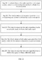
- FIG. 2 is a flowchart of an audio denoising method.
- a procedure is executed by a vehicle.
- the vehicle may alternatively be a component (for example, a processor, a chip, or another component) in the vehicle. This is not limited.
- the procedure shown in FIG. 2 includes but is not limited to the following steps.
- Step 201 The vehicle obtains a first audio signal that is of a target acoustic source in a corresponding area and that is collected by a first microphone.
- Step 202 The vehicle obtains a second audio signal that is of a corresponding area and that is collected by a second microphone.
- the first microphone and the second microphone are disposed in different areas in a target environment, and the first microphone and the second microphone each are configured to collect an audio signal of a target acoustic source (for example, a driver or a passenger) in an area corresponding to each of the first microphone and the second microphone.
- a target acoustic source for example, a driver or a passenger
- the target environment is an environment in a car cabin
- the car cabin may be divided into a plurality of areas based on different types of the car cabin. For example, as shown in FIG. 3 , if the car cabin includes six seats, the cabin may be divided into six areas, and one microphone is disposed in each area.
- one speaker may also be disposed in each area.
- a microphone 1 in an area 1 is configured to collect an audio signal of a target acoustic source (for example, the driver) in the area 1
- a microphone 2 in an area 2 is configured to collect an audio signal of a target acoustic source (for example, a passenger in a passenger seat) in the area 2.
- Processes in which microphones in an area 3 to an area 6 collect an audio signal are similar to the foregoing processes. Details are not described herein again.
- a corresponding solution is: denoising, by using an audio signal collected by a microphone in one area, the first audio signal collected by the first microphone. If there are a plurality of second microphones, a corresponding solution is: denoising, by using audio signals collected by microphones in a plurality of areas, the first audio signal collected by the first microphone.
- the audio signal collected by the microphone 1 in the area 1 may be denoised by using each of audio signals collected by microphones in the area 2, the area 3, an area 4, an area 5, and the area 6.
- the audio signal collected by the microphone 2 in the area 2 may be denoised by using each of audio signals collected in the area 1, the area 3, the area 4, the area 5, and the area 6.
- an audio signal collected by the microphone 3 in the area 3 may be denoised by using each of audio signals collected by microphones in the area 1, the area 2, the area 4, the area 5, and the area 6.
- Processes of denoising audio signals of microphones corresponding to the area 4, the area 5, and the area 6 are similar to the foregoing processes. Details are not described herein again.
- Step 203 The vehicle denoises the first audio signal based on the second audio signal, to obtain a third audio signal.
- step 203 may be as follows: The vehicle performs adaptive filtering on the second audio signal, to obtain a first filtered output signal; the vehicle obtains a first residual signal based on a difference between the first audio signal and the first filtered output signal, where the first residual signal represents an audio signal remaining after interference from the second audio signal is removed from the first audio signal; and the vehicle obtains the third audio signal based on the first residual signal.
- the vehicle may determine the third audio signal based on a frequency domain amplitude comparison between the first residual signal and the first audio signal.
- D m (n) represents a frequency domain representation of the first audio signal
- ED m,m '(n) represents a frequency domain representation of the first residual signal
- D zm (n) represents a frequency domain representation of the third audio signal
- n represents a frame sequence number of an audio signal
- k represents a frequency index sequence number of a frequency domain representation of the audio signal.
- D m (n) is used as an example.
- N represents a length of a processing window of frequency domain transformation used for the frequency domain representation of the audio signal
- m represents an identifier of the first microphone
- m' represents an identifier of the second microphone.
- each second microphone corresponds to one second audio signal.
- a specific implementation of S203 may be as follows: The vehicle separately performs the following processing on each second audio signal, to obtain a residual signal corresponding to each second audio signal: performing adaptive filtering on the second audio signal, to obtain a second filtered output signal; and obtaining a second residual signal based on a difference between the first audio signal and the second filtered output signal.
- a second residual signal corresponding to each second audio signal may be obtained, and a plurality of second residual signals may be obtained in total for the plurality of second audio signals.
- the vehicle may obtain the third audio signal based on the plurality of second residual signals.
- the vehicle may determine the third audio signal based on a frequency domain amplitude comparison between the plurality of second residual signals and the first audio signal.
- D m (n) represents a frequency domain representation of the first audio signal
- ED m,m '(n) represents a frequency domain representation of the plurality of second residual signals
- D zm (n) represents a frequency domain representation of the third audio signal
- n represents a frame sequence number of an audio signal
- k represents a frequency index sequence number of a frequency domain representation of the audio signal
- m represents an identifier of the first microphone
- m' represents identifiers of the plurality of second microphones.
- the first audio signal collected by the first microphone is denoised by using three second audio signals collected by the three second microphones, to obtain the third audio signal.
- the three second microphones are respectively a second microphone A, a second microphone B, and a second microphone C
- second audio signals respectively corresponding to the three second microphones are a second audio signal A, a second audio signal B, and a second audio signal C.
- adaptive filtering may be performed on the second audio signal A, to obtain a second filtered output signal A, and a second residual signal A is obtained based on a difference between the first audio signal and the second filtered output signal A.
- adaptive filtering is performed on the second audio signal B, to obtain a second filtered output signal B, and a second residual signal B is obtained based on the first audio signal and the second filtered output signal B.
- processing similar to the foregoing processing is performed on the second audio signal C, to obtain a second residual signal C.
- the third audio signal may be obtained based on a frequency domain amplitude comparison between the second residual signal A, the second residual signal B, the second residual signal C, and the first audio signal.
- the frequency domain representation of the first audio signal collected by the first microphone may be expressed as [a, b, c, d].
- the frequency domain representation of the first audio signal includes only four frequency elements. It is assumed that a first frequency element a is an audio signal that is of a target acoustic source and that is collected by the first microphone, a second frequency element b is a noise signal caused by an acoustic source corresponding to the second microphone A, a third frequency element c is a noise signal caused by the second microphone B, and a fourth frequency element d is a noise signal caused by the second microphone C.
- the first audio signal collected by the first microphone is denoised by using the second audio signal A collected by the second microphone A, to obtain the second residual signal A, where the second residual signal A may be represented as [a, 0, c, d];
- the first audio signal collected by the first microphone is denoised by using the second audio signal B collected by the second microphone B, to obtain the second residual signal B, where the second residual signal B may be represented as [a, b, 0, d];
- the first audio signal collected by the first microphone is denoised by using the second audio signal C collected by the second microphone C, to obtain a second residual signal C, where the second residual signal C may be represented as [a, b, c, 0]; and a minimum value is assigned to each frequency element in the second residual signal A ([a, 0, c, d
- Step 204 The vehicle obtains a fourth audio signal played by a first speaker, where the first speaker is disposed in a target environment.
- the target environment may be specifically a car cabin, the car cabin may be divided into a plurality of areas, and each area may include one or more speakers. This is not limited. In the example shown in FIG. 3 , descriptions are provided by using an example in which each area includes one speaker.
- Step 205 The vehicle denoises the third audio signal based on the fourth audio signal, to obtain a fifth audio signal, where the fifth audio signal is an audio signal that is of the target acoustic source and that is obtained after interference is filtered out.
- step 205 may be as follows: The vehicle performs adaptive filtering on the fourth audio signal, to obtain a third filtered output signal; and the vehicle obtains a third residual signal based on a difference between the third audio signal and the third filtered output signal, and obtains the fifth audio signal based on the third residual signal.
- the vehicle may determine the fifth audio signal based on a frequency domain amplitude comparison between the third audio signal and the third residual signal.
- D Fm (n) represents a frequency domain representation of the fifth audio signal
- ER m,s (n) represents a frequency domain representation of the third residual signal
- D zm (n) represents a frequency domain representation of the third audio signal
- n represents a frame sequence number of an audio signal
- k represents a frequency index sequence number of a frequency domain representation of the audio signal
- m represents an identifier of the first microphone
- s represents an identifier of the first speaker.
- step 205 may be as follows: The vehicle separately performs the following processing on each fourth audio signal, to obtain a residual signal corresponding to each fourth audio signal: performing adaptive filtering on the fourth audio signal, to obtain a fourth filtered output signal; and obtaining a fourth residual signal based on a difference between the third audio signal and the fourth filtered output signal.
- one corresponding fourth residual signal may be obtained for each fourth audio signal, and a plurality of fourth residual signals may be obtained in total for the plurality of fourth audio signals.
- the vehicle may obtain the fifth audio signal based on the plurality of fourth residual signals.
- the vehicle may determine the fifth audio signal based on a frequency domain amplitude comparison between the third audio signal and the plurality of fourth residual signals.
- D Fm (n) represents a frequency domain representation of the fifth audio signal
- ER m,s (n) represents a frequency domain representation of the plurality of fourth residual signals
- D zm (n) represents a frequency domain representation of the third audio signal
- n represents a frame sequence number of an audio signal
- k represents a frequency index sequence number of a frequency domain representation of the audio signal
- m represents an identifier of the first microphone
- s represents identifiers of the plurality of first speakers.
- the first audio signal collected by the first microphone is denoised by using the second audio signal collected by the second microphone, to obtain the third audio signal.
- the third audio signal is denoised by using the fourth audio signal output by the first speaker, to obtain the fifth audio signal.
- the fifth audio signal is an expected clean audio signal.
- the vehicle-mounted audio system includes K M microphones and Ks speakers is used as an example to describe in detail the denoising procedure shown in FIG. 2 .
- K M and Ks each are a positive integer greater than or equal to 1.
- the vehicle-mounted audio system may be disposed in a target environment (for example, in a car cabin), the target environment may be divided into K M areas, and one microphone and one or more speakers are disposed in each area.
- a microphone 1 in the K M microphones may be disposed in an area 1 of the target environment, to collect an audio signal of a target acoustic source in the area 1.
- a microphone 2 may be disposed in an area 2 of the target environment, to collect an audio signal of a target acoustic source in the area 2.
- a microphone K M may be disposed in an area K M of the target environment, to collect an audio signal of a target acoustic source in the area K M .
- values of K M and Ks are both 6, microphones and speakers may be disposed in different areas with reference to FIG. 3 .
- the audio signal that is of the target acoustic source in the area 1 and that is collected by the microphone 1 may be referred to as a microphone signal 1
- the audio signal that is of the target acoustic source in the area 2 and that is collected by the microphone 2 may be referred to as a microphone signal 2
- the audio signal that is of the target acoustic source in the area K M and that is collected by the microphone K M may be referred to as a microphone signal K M .
- "area” and “zone” have a same concept and may be replaced with each other. Referring to FIG. 4 , audio denoising processes of the K M microphone signals may be as follows:
- An audio denoising process of the microphone signal 1 is as follows: Zone-based suppression is performed on the microphone signal 1 by using the microphone signal 2 and a microphone signal 3 to the microphone signal K M as noise references, to obtain a zone-based noise suppression signal 1. Then, echo cancellation is performed on the zone-based noise suppression signal 1 by using, as echo references, audio signals played by Kr speakers, to obtain a zone-based noise echo suppression signal 1.
- the zone-based noise echo suppression signal 1 is an expected clean audio signal in the area 1.
- 0 ⁇ Kr ⁇ Ks, and Ks is a total quantity of speakers in the entire vehicle-mounted audio system. It can be learned from the foregoing descriptions that the entire vehicle-mounted audio system includes Ks speakers in total.
- Kr When Kr is less than Ks, it represents that an audio signal collected by a microphone is denoised by using, as echo references, audio signals output by some speakers in the vehicle-mounted audio system. For example, speaker signals of first Kr speakers close to a microphone in a current area may be selected as an echo reference.
- Kr when Kr is equal to Ks, it represents that an audio signal collected by a microphone is denoised by using, as echo references, audio signals output by all speakers in the vehicle-mounted audio system.
- Zone-based suppression is performed on the microphone signal 2 by using the microphone signal 1 and the microphone signal 3 to the microphone signal K M as noise references, to obtain a zone-based noise suppression signal 2.
- echo cancellation is performed on the zone-based noise suppression signal 2 by using, as echo references, audio signals played by Kr speakers, to obtain a zone-based noise echo suppression signal 2.
- the zone-based noise echo suppression signal 2 is an expected clean audio signal in the area 2.
- Subsequent audio denoising processes of the microphone signal 3 to the microphone signal K M are similar to the foregoing processes, and are not described one by one. Processes of zone-based suppression and echo cancellation are described in detail in the following embodiments.
- Zone-based suppression is performed on a microphone signal d m (n) collected by a microphone in an m th zone by using, as a noise reference, a microphone signal d m' (n) collected by a microphone in an (m') th zone.
- m and m' each are a positive integer greater than or equal to 1 and less than or equal to K M , and m is not equal to m'.
- an adaptive filtering algorithm WDAF [1] Wu Sheng, Qiu Xiaojun, "A Windowing Frequency Domain Adaptive Filter for Acoustic Echo Cancellation", IEICE Transactions on Fundamentals of Electronics, Communications and Computer Sciences, Volume E92.A, Issue 10, pp.
- the microphone signal d m (n) of the m th zone is converted into frequency domain, to obtain D m (n).
- n a frame sequence number
- N a length of a processing window
- FFT fast Fourier transformation
- w s a window function
- value ranges of M and N are related to a sampling frequency fs of an audio signal, and 0 ⁇ M ⁇ N ⁇ 0.1 fs.
- a value of N may be 1024
- a value of M may be 640.
- XD m ′ n FFT d m ′ n • w a .
- n a frame sequence number
- FFT represents fast Fourier transformation
- w a a window function
- n a frame sequence number
- FFT fast Fourier transformation
- n a frame sequence number
- FFT fast Fourier transformation
- d m ' (n-M/2) [d m' (Nn - N + 1 - M/2), d m' (Nn - N + 2 - M/2), ..., d m' (Nn - M/2)].
- Adaptive filtering is performed on the three frequency domain noise suppression reference signals XD m ' (n), XD Lm ' (n), and XD Cm ' (n), to obtain filtered output signals yd m,m '.
- a specific process may include the following two steps 1.3.1 and 1.3.2.
- Inverse fast Fourier transformation (invert fast Fourier transformation, IFFT) is performed on YD Lm,m' (n) and YD Cm,m' (n), to obtain a filtered output signal yd m,m' obtained after adaptive filtering.
- a frequency domain zone-based noise suppression signal D zm (n)[k] is calculated through frequency-domain fusion, and one with a minimum amplitude in D m (n)[k] and ED m,m' (n)[k] is selected as a value of D zm (n)[k].
- k represents a frequency index sequence number of a frequency domain representation of an audio signal
- m 1, 2, ..., K M
- m' 1, 2, ..., K M
- m' ⁇ m
- D zm (n)[k] is a frequency domain representation of a frequency domain zone-based noise suppression signal.
- An echo in the zone-based noise suppression signal in the zone is suppressed by using an adaptive filtering algorithm (for example, a process of echo cancellation), to obtain a zone-based noise echo suppression signal in each zone.
- an adaptive filtering algorithm for example, a process of echo cancellation
- FFT transformation is performed on a speaker signal r s (n) played by a speaker s, to obtain three frequency domain echo suppression signals XR s (n), XR Cs (n), and XR Ls (n).
- XR s n FFT r s n • w a .
- n a frame sequence number
- FFT represents fast Fourier transformation
- w a a window function
- n a frame sequence number
- FFT fast Fourier transformation
- n a frame sequence number
- FFT represents fast Fourier transformation
- r s (n - M/2) [r s (Nn - N + 1 - M/2), r s (Nn - N + 2 - M/2), ..., r s (Nn - M/2)]
- r s (n) [r s (Nn - N + 1), r s (Nn - N + 2), ..., r s (Nn)].
- the three frequency domain echo suppression signals XR s (n), XR Cs (n), and XR Ls (n) are input into an adaptive filter, to obtain a filtered output yr m,s (n).
- IFFT transformation is performed on YR Lm,s (n) and YR Cms (n), to obtain a filtered output signal yr m,s obtained after adaptive filtering.
- a frequency domain filtered output YR m,s (n) is calculated.
- YR m , s n FFT yr m , s n • w s .
- n a frame sequence number
- FFT fast Fourier transformation
- w s a window function
- a frequency domain filtered residual signal is calculated.
- ER m , s n D z m n ⁇ YR m , s n .
- a frequency domain zone-based noise echo suppression signal D Fm (n) is calculated through frequency-domain fusion, and one with a minimum amplitude in D zm (n)[k] and ER m,s (n)[k] is selected as a value of D Fm (n)[k].
- k represents a frequency index sequence number of a frequency domain representation of an audio signal
- m 1, 2, ..., K M
- s 1, 2, ..., Kr
- D Fm (n) is a frequency domain zone-based noise echo suppression signal, namely, an expected clean signal.
- the speaker signal r s (n) may be used as an echo reference for the zone-based noise suppression signal of each zone.
- the speaker signal r s (n) may be speaker signals of some speakers, for example, speaker signals of some speakers near an area of a current microphone. For example, for an m th area, sequence numbers of speakers close to a microphone in the area may include s 1 , s 2 , ..., s m .
- echo cancellation may be performed on a zone-based noise suppression signal by using only speaker signals of the m speakers. Therefore, computing resource consumption of echo cancellation can be reduced when echo suppression performance is ensured.
- the audio denoising method provided in this embodiment of this application may be used to denoise an audio denoising method collected by a microphone. It is assumed there is a 4-zone vehicle-mounted audio system, including four microphones. The four microphones are respectively located in an area of a driving seat, an area of a passenger seat, an area of a left back seat, and an area of a right back seat.
- a microphone 1 in the four microphones is configured to collect an audio signal of the driving seat in the area of the driving seat
- a microphone 2 is configured to collect an audio signal of a passenger seat in the area of the passenger seat
- a microphone 3 is configured to collect an audio signal of a left back passenger in the area of the left back seat
- a microphone 4 is configured to collect an audio signal of a right back passenger in the area of the right back seat.
- a method and an operation implemented by a vehicle may also be implemented by a component (for example, a chip, a circuit, or another component) in the vehicle.
- the vehicle may include a hardware structure and/or a software module, to implement the foregoing functions in a form of the hardware structure, the software module, or a combination of the hardware structure and the software module. Whether one of the foregoing functions is performed in the manner of the hardware structure, the software unit, or the hardware structure and the software unit depends on a specific application and design constraints of the technical solutions.
- FIG. 6 is a schematic block diagram of an apparatus 600 according to an embodiment of this application.
- the apparatus 600 is configured to implement a function of the vehicle in the foregoing method.
- the apparatus may be a software unit or a chip system.
- the chip system may include a chip, or may include a chip and another discrete device.
- the apparatus may include an obtaining unit 601, a zone-based suppression unit 602, and an echo cancellation unit 603.
- the obtaining unit 601 is configured to obtain a first audio signal that is of a target acoustic source in a corresponding area and that is collected by a first microphone, a second audio signal that is of a target acoustic source in a corresponding area and that is collected by a second microphone, and a fourth audio signal played by a first speaker, where the first microphone, the second microphone, and the first speaker are disposed in a target environment, and the first microphone and the second microphone are disposed in different areas of the target environment.
- the zone-based suppression unit 602 is configured to denoise the first audio signal based on the second audio signal, to obtain a third audio signal.
- the echo cancellation unit 603 is configured to denoise the third audio signal based on the fourth audio signal, to obtain a fifth audio signal, where the fifth audio signal is an audio signal that is of the target acoustic source and that is obtained after interference is filtered out.
- That the zone-based suppression unit 602 denoises the first audio signal based on the second audio signal, to obtain a third audio signal includes: performing adaptive filtering on the second audio signal, to obtain a first filtered output signal; obtaining a first residual signal based on a difference between the first audio signal and the first filtered output signal; and obtaining the third audio signal based on the first residual signal.
- zone-based suppression unit 602 obtains the third audio signal based on the first residual signal includes: determining the third audio signal based on a frequency domain amplitude comparison between the first residual signal and the first audio signal.
- the zone-based suppression unit 602 denoises the first audio signal based on the second audio signal, to obtain a third audio signal includes: separately performing the following processing on each second audio signal, to obtain a residual signal corresponding to each second audio signal: performing adaptive filtering on the second audio signal, to obtain a second filtered output signal; obtaining a second residual signal based on a difference between the first audio signal and the second filtered output signal; and obtaining the third audio signal based on a plurality of second residual signals.
- zone-based suppression unit 602 obtains the third audio signal based on a plurality of second residual signals includes: determining the third audio signal based on a frequency domain amplitude comparison between the first audio signal and the plurality of second residual signals.
- That the echo cancellation unit 603 denoises the third audio signal based on the fourth audio signal, to obtain a fifth audio signal includes: performing adaptive filtering on the fourth audio signal, to obtain a third filtered output signal; obtaining a third residual signal based on a difference between the third audio signal and the third filtered output signal; and obtaining the fifth audio signal based on the third residual signal.
- that the echo cancellation unit 603 obtains the fifth audio signal based on the third residual signal includes: determining the fifth audio signal based on a frequency domain amplitude comparison between the third audio signal and the third residual signal.
- That the echo cancellation unit 603 denoises the third audio signal based on the fourth audio signal, to obtain a fifth audio signal includes: separately performing the following processing on each fourth audio signal, to obtain a residual signal corresponding to each fourth audio signal: performing adaptive filtering on the fourth audio signal, to obtain a fourth filtered output signal; obtaining a fourth residual signal based on a difference between the third audio signal and the fourth filtered output signal; and obtaining the fifth audio signal based on a plurality of fourth residual signals.
- the echo cancellation unit 603 obtains the fifth audio signal based on a plurality of fourth residual signals includes: determining the fifth audio signal based on a frequency domain amplitude comparison between the third audio signal and the plurality of fourth residual signals.
- FIG. 6 may be implemented by a processor, may be implemented by a hardware circuit, may be implemented in another manner, or the like. This is not limited.
- Division into the units in embodiments of this application is an example, is merely division into logical functions, and may be other division during actual implementation.
- functional units in embodiments of this application may be integrated into one processor, or each of the units may exist alone physically, or two or more units may be integrated into one unit.
- the integrated unit may be implemented in a form of hardware, or may be implemented in a form of a software functional unit.
- FIG. 7 is a schematic block diagram of an apparatus 700 according to an embodiment of this application.
- the apparatus is applicable to the procedure in FIG. 2 , and perform a function of the vehicle in the method embodiment.
- FIG. 7 shows only a main component of the communication apparatus.
- the communication apparatus 700 shown in FIG. 7 includes at least one processor 701.
- the communication apparatus 700 may further include at least one memory 702, configured to store program instructions and/or data.
- the memory 702 is coupled to the processor 701.
- the coupling in this embodiment of this application is an indirect coupling or a communication connection between apparatuses, units, or modules, may be in an electrical form, a mechanical form, or another form, and is used for information exchange between the apparatuses, the units, or the modules.
- the processor 701 may cooperate with the memory 702, the processor 701 may execute the program instructions stored in the memory 702, and at least one of the at least one memory 702 may be included in the processor 701.
- the apparatus 700 may further include a communication interface 703, configured to communicate with another device by using a transmission medium, so that the communication apparatus 700 may communicate with the another device.
- the communication interface may be a transceiver, a circuit, a bus, a module, or another type of communication interface.
- the transceiver when the communication interface is a transceiver, the transceiver may include an independent receiver and an independent transmitter, or may be a transceiver on which receiving and sending functions are integrated, or an interface circuit.
- connection medium between the processor 701, the memory 702, and the communication interface 703 is not limited in this embodiment of this application.
- the memory 702, the processor 701, and the communication interface 703 are connected by using a communication bus 704.
- the bus is represented by using a thick line in FIG. 7 .
- a manner of connecting other components is merely an example for description, and does not impose a limitation.
- the bus may include an address bus, a data bus, a control bus, and the like.
- FIG. 7 only one thick line is used for representation, but this does not mean that there is only one bus, only one type of bus, or the like.
- the processor 701 is configured to: obtain a first audio signal that is of a target acoustic source in a corresponding area and that is collected by a first microphone, and obtain a second audio signal that is of a target acoustic source in a corresponding area and that is collected by a second microphone and a fourth audio signal played by a first speaker, where the first microphone, the second microphone, and the first speaker are disposed in a target environment, and the first microphone and the second microphone are disposed in different areas of the target environment.
- the processor 701 is further configured to: denoise the first audio signal based on the second audio signal, to obtain a third audio signal; and denoise the third audio signal based on the fourth audio signal, to obtain a fifth audio signal, where the fifth audio signal is an audio signal that is of the target acoustic source and that is obtained after interference is filtered out.
- the processor 701 denoises the first audio signal based on the second audio signal, to obtain a third audio signal includes: performing adaptive filtering on the second audio signal, to obtain a first filtered output signal; obtaining a first residual signal based on a difference between the first audio signal and the first filtered output signal; and obtaining the third audio signal based on the first residual signal.
- the processor 701 obtains the third audio signal based on the first residual signal includes: determining the third audio signal based on a frequency domain amplitude comparison between the first residual signal and the first audio signal.
- the processor 701 denoises the first audio signal based on the second audio signal, to obtain a third audio signal includes: separately performing the following processing on each second audio signal, to obtain a residual signal corresponding to each second audio signal: performing adaptive filtering on the second audio signal, to obtain a second filtered output signal; obtaining a second residual signal based on a difference between the first audio signal and the second filtered output signal; and obtaining the third audio signal based on a plurality of second residual signals.
- the processor 701 obtains the third audio signal based on a plurality of second residual signals includes: determining the third audio signal based on a frequency domain amplitude comparison between the first audio signal and the plurality of second residual signals.
- the processor 701 denoises the third audio signal based on the fourth audio signal, to obtain a fifth audio signal includes: performing adaptive filtering on the fourth audio signal, to obtain a third filtered output signal; obtaining a third residual signal based on a difference between the third audio signal and the third filtered output signal; and obtaining the fifth audio signal based on the third residual signal.
- that the processor 701 obtains the fifth audio signal based on the third residual signal includes: determining the fifth audio signal based on a frequency domain amplitude comparison between the third audio signal and the third residual signal.
- the processor 701 denoises the third audio signal based on the fourth audio signal, to obtain a fifth audio signal includes: separately performing the following processing on each fourth audio signal, to obtain a residual signal corresponding to each fourth audio signal: performing adaptive filtering on the fourth audio signal, to obtain a fourth filtered output signal; obtaining a fourth residual signal based on a difference between the third audio signal and the fourth filtered output signal; and obtaining the fifth audio signal based on a plurality of fourth residual signals.
- the processor 701 obtains the fifth audio signal based on a plurality of fourth residual signals includes: determining the fifth audio signal based on a frequency domain amplitude comparison between the third audio signal and the plurality of fourth residual signals.
- an embodiment of this application further provides an apparatus.
- the apparatus is configured to perform the method in the procedure shown in FIG. 2 .
- a computer-readable storage medium includes a program. When the program is run by a processor, the method in the procedure shown in FIG. 2 is performed.
- a computer program product is provided.
- the computer program product includes computer program code, and when the computer program code is run on a computer, the computer is enabled to perform the method in the procedure shown in FIG. 2 .
- a chip is provided, and includes a processor.
- the processor is coupled to a memory, the memory is configured to store a program or instructions, and when the program or the instructions are executed by the processor, the apparatus is enabled to perform the method in the procedure shown in FIG. 2 .
- the processor may be a general-purpose processor, a digital signal processor, an application-specific integrated circuit, a field programmable gate array or another programmable logic device, a discrete gate or transistor logic device, or a discrete hardware component, and may implement or execute the methods, steps, and logical block diagrams disclosed in embodiments of this application.
- the general-purpose processor may be a microprocessor, any conventional processor, or the like. The steps in the methods disclosed with reference to embodiments of this application may be directly performed by a hardware processor, or may be performed by using a combination of hardware in the processor and a software module.
- the memory may be a nonvolatile memory, for example, a hard disk drive (hard disk drive, HDD) or a solid state drive (solid-state drive, SSD), or may be a volatile memory (volatile memory), for example, a random access memory (random-access memory, RAM).
- the memory is any other medium that can be configured to carry or store expected program code in a form of an instruction structure or a data structure and that can be accessed by a computer, but is not limited thereto.
- the memory in this embodiment of this application may be alternatively a circuit or any other apparatus that can implement a storage function, and is configured to store program instructions and/or data.
- All or some of the methods provided in embodiments of this application may be implemented by using software, hardware, firmware, or any combination thereof.
- software is used to implement the methods, all or some of the methods may be implemented in a form of a computer program product.
- the computer program product includes one or more computer instructions.
- the computer may be a general-purpose computer, a dedicated computer, a computer network, a network device, user equipment, or another programmable apparatus.
- the computer instructions may be stored in a computer-readable storage medium or may be transmitted from a computer-readable storage medium to another computer-readable storage medium.
- the computer instructions may be transmitted from a website, computer, server, or data center to another website, computer, server, or data center in a wired (for example, a coaxial cable, an optical fiber, or a digital subscriber line (digital subscriber line, DSL for short)) or wireless (for example, infrared, radio, or microwave) manner.
- the computer-readable storage medium may be any usable medium accessible by a computer, or a data storage device, for example, a server or a data center, integrating one or more usable media.
- the usable medium may be a magnetic medium (for example, a floppy disk, a hard disk, or a magnetic tape), an optical medium (for example, a digital video disc (digital video disc, DVD for short)), a semiconductor medium (for example, an SSD), or the like.
- a magnetic medium for example, a floppy disk, a hard disk, or a magnetic tape
- an optical medium for example, a digital video disc (digital video disc, DVD for short)
- a semiconductor medium for example, an SSD
Landscapes
- Engineering & Computer Science (AREA)
- Physics & Mathematics (AREA)
- Acoustics & Sound (AREA)
- Multimedia (AREA)
- Signal Processing (AREA)
- Health & Medical Sciences (AREA)
- Audiology, Speech & Language Pathology (AREA)
- General Health & Medical Sciences (AREA)
- Human Computer Interaction (AREA)
- Quality & Reliability (AREA)
- Computational Linguistics (AREA)
- Otolaryngology (AREA)
- Circuit For Audible Band Transducer (AREA)
- Fittings On The Vehicle Exterior For Carrying Loads, And Devices For Holding Or Mounting Articles (AREA)
Abstract
Description
- The present invention relates to the field of automated driving technologies, and in particular, to an audio denoising method and an apparatus.
- A vehicle-mounted audio system may include components such as a microphone and a speaker. The microphone may collect an audio signal entered by a user, and the speaker may play the audio signal to the outside. The audio signal collected by the microphone is affected by the speaker. How to denoise the audio signal collected by the microphone is a technical problem to be resolved currently.
- Embodiments of this application provide an audio denoising method and an apparatus, to denoise an audio signal collected by a microphone.
- According to a first aspect, an audio denoising method is provided. The method is performed by a vehicle. It can be understood that the vehicle may be further a component (for example, a chip or a circuit) in the vehicle. The vehicle may include a first microphone, a second microphone, and a first speaker, the first microphone and the second microphone may be disposed in different areas in a target environment, the first microphone is configured to collect a first audio signal of a first target acoustic source in an area corresponding to the first microphone, and the second microphone is configured to collect a second audio signal of a second target acoustic source in an area corresponding to the second microphone. In other words, the first audio signal and the second audio signal each are an audio signal collected by a corresponding microphone at a location at which the microphone is disposed. The method may include: The vehicle obtains the first audio signal that is of the first target acoustic source in the corresponding area and that is collected by the first microphone; the vehicle obtains the second audio signal that is of the second target acoustic source in the corresponding area and that is collected by the second microphone; the vehicle obtains a fourth audio signal played by the first speaker; the vehicle denoises the first audio signal by using the second audio signal, to obtain a third audio signal, where the third audio signal may be an audio signal obtained after interference from the second target acoustic source is filtered out from the first audio signal; and the vehicle denoises the third audio signal by using the fourth audio signal, to obtain a fifth audio signal, where the fifth audio signal may be an audio signal obtained after interference from the second target acoustic source and the fourth audio signal is filtered out from the first audio signal.
- In the foregoing solution, that the first microphone and the second microphone may be disposed in different areas in the target environment may mean that a microphone deployed in a vehicle cabin is disposed at different locations in the vehicle based on a collection requirement. For example, a location of the microphone may be disposed based on a general distribution situation that is of passengers in the vehicle and that exists when the vehicle is in use. A microphone disposed in an area of a driver or disposed close to the driver is a microphone configured to collect a voice of the driver. Similarly, a microphone disposed in an area of a passenger seat or disposed in an area of a back seat is configured to collect a voice signal of a passenger in the passenger seat or a passenger in the back seat.
- Usually, although the first microphone is to collect an audio signal of a target acoustic source, due to connectivity of space inside the vehicle, both an audio signal played in a different area and a voice signal of a person interfere with audio collection of a target object and a target acoustic source that are to be collected. Therefore, a collected first microphone signal is a mixed audio signal of various sound signals collected in a driving seat, and similarly, another microphone also collects a mixed signal that is of all acoustic sources and that can be received at a current location.
- In the method, first, the first audio signal collected by the first microphone is denoised by using the second audio signal collected by the second microphone, to obtain the third audio signal. Then, the third audio signal is denoised by using the fourth audio signal played by the first speaker, to obtain the fifth audio signal. The fifth audio signal is an expected clean audio signal. Compared with an existing solution in which an audio signal collected by a microphone is directly denoised by using an audio signal played by a speaker, in the method, denoising overheads can be reduced, and a denoising effect can be improved. A reason is as follows: In the existing solution, an audio signal collected by one microphone needs to be denoised once based on all speakers in a vehicle-mounted audio system. However, in this embodiment of this application, only some speakers in the vehicle-mounted audio system need to be used for denoising, to achieve a good denoising effect, and reduce denoising overheads. It should be noted that in this embodiment of this application, some or all speakers in the vehicle-mounted audio system are used for denoising. This is not limited.
- In a possible implementation, when there is one second microphone, there is also one second audio signal. The process of denoising the first audio signal based on the second audio signal, to obtain a third audio signal may include: performing adaptive filtering on the second audio signal, to obtain a first filtered output signal; obtaining a first residual signal based on a difference between the first audio signal and the first filtered output signal, where the first residual signal represents an audio signal remaining after the interference from the second audio signal is removed from the first audio signal; and obtaining the third audio signal based on the first residual signal. For example, the third audio signal may be determined based on a frequency domain amplitude comparison between the first residual signal and the first audio signal. Further, the first residual signal, the first audio signal, and the third audio signal may satisfy the following formula:

- Herein, D m(n) represents a frequency domain representation of the first audio signal, ED m,m'(n) represents a frequency domain representation of the first residual signal, D zm(n) represents a frequency domain representation of the third audio signal, n represents a frame sequence number of an audio signal, k represents a frequency index sequence number of a frequency domain representation of the audio signal, m represents an identifier of the first microphone, and m' represents an identifier of the second microphone.
- In a possible implementation, when there are a plurality of second microphones, there are also a plurality of second audio signals, and each second microphone corresponds to one second audio signal. The plurality of second microphones may be disposed in a same area or may be disposed in different areas. The process of denoising the first audio signal based on the second audio signal, to obtain a third audio signal may include: separately performing the following processing on each second audio signal, to obtain a residual signal corresponding to each second audio signal: performing adaptive filtering on the second audio signal, to obtain a second filtered output signal; and obtaining a second residual signal based on a difference between the first audio signal and the second filtered output signal. Through processing in the foregoing process, for each second audio signal, the second residual signal corresponding to each second audio signal may be obtained, and a plurality of second residual signals may be obtained in total for the plurality of second audio signals. In this case, the third audio signal may be obtained based on the plurality of second residual signals. For example, the third audio signal may be determined based on a frequency domain amplitude comparison between the plurality of second residual signals and the first audio signal. Further, the plurality of second residual signals, the first audio signal, and the third audio signal may satisfy the following formula:

- Herein, D m(n) represents a frequency domain representation of the first audio signal, ED m,m'(n) represents a frequency domain representation of the plurality of second residual signals, D zm(n) represents a frequency domain representation of the third audio signal, n represents a frame sequence number of an audio signal, k represents a frequency index sequence number of a frequency domain representation of the audio signal, m represents an identifier of the first microphone, and m' represents identifiers of the plurality of second microphones.
- It should be noted that, in the foregoing formula, m' represents the identifiers of the plurality of second microphones. It can be learned from the foregoing descriptions that for a second audio signal collected by each second microphone, a second residual signal corresponding to the second audio signal may be obtained. When m' represents the identifiers of the plurality of second microphones, EDm,m' (n) may represent a plurality of second residual signals respectively corresponding to the plurality of second microphones. For example, a value of m' may be 2 or 3 when the first audio signal collected by the first microphone is denoised by using audio signals collected by a
microphone 2 and amicrophone 3. A frequency domain second residual signal EDm,2 (n)[k] corresponding to m' may be obtained when the value of m' is 2. A frequency domain second residual signal EDm,3 (n)[k] corresponding to m' may be obtained when the value of m' is 3. In a subsequent frequency domain amplitude comparison, frequency domain amplitudes of Dm (n)[k], EDm,2 (n)[k], and EDm,3 (n)[k] may be compared. In other words, in this example, the foregoing formula may be specifically: |Dzm (n)[k]| = min{|Dm (n)[k]|, |EDm,2 (n)[k]|, |EDm,3 (n)[k]|}. - In the method, a process of denoising an audio signal collected by the first microphone based on an audio signal collected by another microphone may also be referred to as a process of zone-based suppression. In this embodiment of this application, concepts of "zone" and "area" are the same, and may be replaced with each other. According to the method, impact of an acoustic source in another area on the first audio signal may be filtered out.
- In a possible implementation, there may be one first speaker, and there may be one fourth audio signal. The process of denoising the third audio signal based on the fourth audio signal, to obtain a fifth audio signal may include: performing adaptive filtering on the fourth audio signal, to obtain a third filtered output signal; obtaining a third residual signal based on a difference between the third audio signal and the third filtered output signal; and obtaining the fifth audio signal based on the third residual signal. For example, the fifth audio signal may be determined based on a frequency domain amplitude comparison between the third audio signal and the third residual signal. Further, the third audio signal, the third residual signal, and the fifth audio signal may satisfy the following formula:

- Herein, DFm (n) represents a frequency domain representation of the fifth audio signal, ERm,s (n) represents a frequency domain representation of the third residual signal, D zm(n) represents a frequency domain representation of the third audio signal, n represents a frame sequence number of an audio signal, k represents a frequency index sequence number of a frequency domain representation of the audio signal, m represents an identifier of the first microphone, and s represents an identifier of the first speaker.
- In a possible implementation, there are a plurality of first speakers, and each speaker plays one fourth audio signal. The plurality of first speakers correspond to a plurality of fourth audio signals. The process of denoising the third audio signal based on the fourth audio signal, to obtain a fifth audio signal may include: separately performing the following processing on each fourth audio signal, to obtain a residual signal corresponding to each fourth audio signal: performing adaptive filtering on the fourth audio signal, to obtain a fourth filtered output signal; and obtaining a fourth residual signal based on a difference between the third audio signal and the fourth filtered output signal. Through the foregoing processing, one corresponding fourth residual signal may be obtained for each fourth audio signal, and a plurality of fourth residual signals may be obtained in total for the plurality of fourth audio signals. Then, the fifth audio signal may be obtained based on the plurality of fourth residual signals. For example, the fifth audio signal may be determined based on a frequency domain amplitude comparison between the third audio signal and the plurality of fourth residual signals. For example, the third audio signal, the plurality of fourth residual signals, and the fifth audio signal may satisfy the following formula:

- Herein, DFm (n) represents a frequency domain representation of the fifth audio signal, ERm,s (n) represents a frequency domain representation of the plurality of fourth residual signals, D zm(n) represents a frequency domain representation of the third audio signal, n represents a frame sequence number of an audio signal, k represents a frequency index sequence number of a frequency domain representation of the audio signal, m represents an identifier of the first microphone, and s represents identifiers of the plurality of first speakers.
- It should be noted that, in the foregoing formula, s represents the identifiers of the plurality of first speakers. It can be learned from the foregoing descriptions that for a fourth audio signal played by each first speaker, a fourth residual signal corresponding to the fourth audio signal may be obtained. When s represents the identifiers of the plurality of first speakers, ERm,s (n)[k] represents a plurality of fourth residual signals respectively corresponding to the plurality of first speakers. For example, when the third audio signal is denoised by using audio signals played by a
speaker 1 and aspeaker 2, the identifiers of the first speakers may be 1 and 2. In other words, a value of s may be 1 or 2. When the value of s is 1, a frequency domain second residual signal ERm,1 (n)[k] corresponding to s may be obtained. When the value of s is 2, a frequency domain second residual signal ERm,2 (n)[k] corresponding to s may be obtained. In a subsequent frequency domain amplitude comparison, frequency domain amplitudes of Dzm (n)[k], ERm,1 (n)[k], and ERm,2 (n)[k] may be compared. In this example, the foregoing formula may be specifically:
- In the method, a process of denoising the third audio signal by using an audio signal played by a speaker may also be referred to as a process of echo cancellation. In this embodiment of this application, all speakers in the vehicle-mounted audio system may be used for echo cancellation, or some speakers in the vehicle-mounted audio system may be used for echo cancellation. For example, some speakers close to an area of the first microphone may be selected for echo cancellation, or the like. Therefore, computing resource consumption of echo cancellation can be reduced when echo cancellation performance is ensured.
- According to a second aspect, an apparatus is provided, to implement the method in the first aspect. The apparatus includes a corresponding unit or module configured to perform the method. The apparatus may be implemented by using software and/or hardware. The apparatus may be a vehicle, or may be a chip, a chip system, a processor, or the like that supports a vehicle to implement the method.
- According to a third aspect, an apparatus is provided, including a processor. The processor is coupled to a memory, the memory is configured to store a program or instructions, and when the program or the instructions are executed by the processor, the apparatus is enabled to implement the method in the first aspect.
- According to a fourth aspect, a computer-readable storage medium is provided. The computer-readable storage medium stores a computer program or instructions, and when the computer program or instructions are executed, a computer is enabled to perform the method in the first aspect.
- According to a fifth aspect, an embodiment of this application provides a computer program product. The computer program product includes computer program code, and when the computer program code is run on a computer, the computer is enabled to perform the method in the first aspect.
- According to a sixth aspect, an embodiment of this application provides a chip, including a processor. The processor is coupled to a memory, the memory is configured to store a program or instructions, and when the program or the instructions are executed by the processor, the chip is enabled to implement the method in the first aspect.
-
-
FIG. 1 is a schematic diagram of a structure of a vehicle-mounted audio system according to an embodiment of this application; -
FIG. 2 is a schematic flowchart of an audio denoising method according to an embodiment of this application; -
FIG. 3 is a schematic diagram of a 6-zone vehicle-mounted audio system according to an embodiment of this application; -
FIG. 4 is a schematic diagram of a principle of an audio denoising method according to an embodiment of this application; -
FIG. 5a is a schematic diagram of a comparison between audio signals that correspond to a driving seat and that exist before and after denoising according to an embodiment of this application; -
FIG. 5b is a schematic diagram of a comparison between audio signals that correspond to a passenger seat and that exist before and after denoising according to an embodiment of this application; -
FIG. 5c is a schematic diagram of a comparison between audio signals that correspond to a left back seat and that exist before and after denoising according to an embodiment of this application; -
FIG. 5d is a schematic diagram of a comparison between audio signals that correspond to a right back seat and that exist before and after denoising according to an embodiment of this application; -
FIG. 6 is a schematic diagram of a structure of an apparatus according to an embodiment of this application; and -
FIG. 7 is a schematic diagram of another structure of an apparatus according to an embodiment of this application. - The following describes the technical solutions in embodiments of this application with reference to the accompanying drawings in embodiments of this application. In descriptions of this application, unless otherwise specified, "/" indicates an "or" relationship between associated objects. For example, A/B may indicate A or B. In this application, "and/or" describes only an association relationship for describing the associated objects, and represents that three relationships may exist. For example, A and/or B may represent the following three cases: Only A exists, both A and B exist, and only B exists. A and B may be singular or plural. In addition, in the descriptions of this application, unless otherwise specified, "a plurality of" means two or more than two. "At least one of the following items (pieces)" or a similar expression thereof refers to any combination of these items, including any combination of singular items (pieces) or plural items (pieces). For example, at least one of a, b, or c may indicate: a, b, c, a and b, a and c, b and c, or a, b, and c, where a, b, and c may be singular or plural. In addition, to clearly describe the technical solutions in embodiments of this application, terms such as "first" and "second" are used in embodiments of this application to distinguish between same items or similar items that have basically the same functions or purposes. A person skilled in the art may understand that the terms such as "first" and "second" do not limit a quantity or an execution sequence, and the terms such as "first" and "second" do not indicate a definite difference.
- In addition, a network architecture and a service scenario described in embodiments of this application are intended to describe the technical solutions in embodiments of this application more clearly, and constitute no limitation on the technical solutions provided in embodiments of this application. A person of ordinary skill in the art may learn that with evolution of the network architecture and emergence of a new service scenario, the technical solutions provided in embodiments of this application are also applicable to similar technical problems.
- The following describes names or terms used in embodiments of this application.
- An adaptive filtering algorithm in embodiment of this application includes but is not limited to a least mean square (least mean square, LMS) adaptive filter, a normalized least mean square (normalized least mean square, NLMS) adaptive filter, a recursive least squares (recursive least squares, RLS) adaptive filter, affine projection (affine projection, AP), a frequency-domain adaptive filter (frequency-domain adaptive filter, FDAF), a multi-direction adaptive filter (multi-direction adaptive filter, MDAF), a windowing frequency domain adaptive filter (windowing frequency domain adaptive filtering, WDAF), or the like. In embodiments of this application, a WDAF filtering algorithm is used as an example for description.
- A principle of the adaptive filtering algorithm may be as follows: A transfer function from a noise source to a target acoustic source is determined through modeling performed based on the adaptive filtering algorithm; and the noise source is filtered by using the transfer function, to obtain a filtered output signal. The filtered output signal is impact of the noise source on the target acoustic source. It is assumed that a
microphone 1 is configured to collect a voice signal V1 output by anacoustic source 1, and anacoustic source 2 is also speaking. Therefore, in addition to the voice signal V1, an audio signal collected by themicrophone 1 may include noise caused by theacoustic source 2. In embodiments of this application, a transfer function h21 from theacoustic source 2 to theacoustic source 1 may be calculated based on the adaptive filtering algorithm, and a noise source V2 is filtered by using the transfer function h21, to obtain a filtered output signal V2∗h21. The obtained filtered output signal is the noise caused by theacoustic source 2. - It should be noted that it is very difficult to obtain a true transfer function between two acoustic sources through modeling performed based on the adaptive filtering algorithm, and the obtained transfer function is usually approximate or close to the true transfer function between the two acoustic sources. For ease of description, descriptions are provided by using an example in which the transfer function between the two acoustic sources that is obtained through modeling performed based on the adaptive filtering algorithm is the true transfer function between the two acoustic sources. Unless otherwise specified, the obtained transfer function and the true transfer function are not distinguished.
- An entire vehicle-mounted audio system includes a speaker in addition to a microphone. When the microphone collects an audio signal of a target acoustic source, the speaker plays the audio signal to the outside. The audio signal played by the speaker affects collection that is of the audio signal of the acoustic source and that is performed by the microphone. Because both the microphone and the speaker belong to the vehicle-mounted audio system, the foregoing process may be considered as follows: The entire vehicle-mounted audio system plays the audio signal to the outside when collecting the audio signal of the acoustic source. The audio signal played by the speaker to the outside may also be referred to as an echo. Canceling the impact exerted by the speaker on the audio signal collected by the microphone is also referred to as echo cancellation.
- It should be noted that in descriptions of the following embodiments, a bold letter represents a vector or matrix, for example, dm (n). A non-bold letter represents a scalar, for example, dm(n).
-
FIG. 1 is a schematic diagram of a vehicle-mounted audio system according to an embodiment of this application. For brevity, only various system aspects are described, but a user interface and a detailed style aspect are omitted. The vehicle-mounted audio system may include astation 10 and astation 14. - The
station 10 includes control and display functions associated with the user interface. A visual form of a display may be a character, ordinary light, a graphic, an animation, or the like. In principle, voice output is feasible. Similarly, a controller may be in a form of a button, a rotary switch, a potentiometer, or a voice input. As shown inFIG. 1 , the station has apower supply connection 11, and is connected to a vehicle-mounted battery or a vehicle power supply system, and the vehicle power supply system may be switched on/off by using a main ignition switch. This is not limited. Finally, thestation 10 is connected to an RF bus/link 12 by using a radio frequency (radio frequency, RF) transceiver, and the RF bus/link 12 may be connected to an RF transceiver of thestation 14, to implement communication between thestation 10 and thestation 14. Thestation 10 is usually mounted within a reachable range of a driver, for example, mounted at a location such as a dash board, a steering wheel, an armrest, or an arm of the driver. - The
station 14 includes apower supply 13, and may further include a speaker, a microphone, an antenna, or the like. Usually, thestation 14 may be mounted at any location at which there is enough space in a passenger cabin, and may even be mounted at a location under the dash board or inserted into the dashboard. Like thestation 10, thestation 14 has an RF transceiver, and the RF transceiver is connected to the RFbus\link 12, to implement communication with thestation 10. - It can be learned from the foregoing descriptions that the vehicle-mounted audio system shown in
FIG. 1 may include a microphone and a speaker. The microphone is configured to collect an audio signal of a target acoustic source (for example, a passenger or the driver), and the speaker is configured to play the audio signal to the outside. An audio signal collected by one microphone is mainly affected by two aspects: an audio signal output by another acoustic source, and the audio signal played by the speaker. How to denoise an audio signal collected by one microphone, for example, a first microphone is a problem to be resolved in this application. - This application provides an audio denoising method and an apparatus. The method includes: denoising, based on a second audio signal collected by a second microphone, a first audio signal collected by a first microphone, to obtain a third audio signal; and denoising the third audio signal by using a fourth audio signal output by the first speaker, to obtain a fifth audio signal. The fifth audio signal is an expected clean audio signal.
-
FIG. 2 is a flowchart of an audio denoising method. A procedure is executed by a vehicle. It can be understood that the vehicle may alternatively be a component (for example, a processor, a chip, or another component) in the vehicle. This is not limited. The procedure shown inFIG. 2 includes but is not limited to the following steps. - Step 201: The vehicle obtains a first audio signal that is of a target acoustic source in a corresponding area and that is collected by a first microphone.
- Step 202: The vehicle obtains a second audio signal that is of a corresponding area and that is collected by a second microphone.
- The first microphone and the second microphone are disposed in different areas in a target environment, and the first microphone and the second microphone each are configured to collect an audio signal of a target acoustic source (for example, a driver or a passenger) in an area corresponding to each of the first microphone and the second microphone. An example in which the target environment is an environment in a car cabin is used to describe the foregoing process: Usually, the car cabin may be divided into a plurality of areas based on different types of the car cabin. For example, as shown in
FIG. 3 , if the car cabin includes six seats, the cabin may be divided into six areas, and one microphone is disposed in each area. Optionally, one speaker may also be disposed in each area. Amicrophone 1 in anarea 1 is configured to collect an audio signal of a target acoustic source (for example, the driver) in thearea 1, and amicrophone 2 in anarea 2 is configured to collect an audio signal of a target acoustic source (for example, a passenger in a passenger seat) in thearea 2. Processes in which microphones in anarea 3 to anarea 6 collect an audio signal are similar to the foregoing processes. Details are not described herein again. - In this embodiment of this application, there is usually one first microphone, and there may be one or more second microphones. With reference to the foregoing descriptions, if there is one second microphone, a corresponding solution is: denoising, by using an audio signal collected by a microphone in one area, the first audio signal collected by the first microphone. If there are a plurality of second microphones, a corresponding solution is: denoising, by using audio signals collected by microphones in a plurality of areas, the first audio signal collected by the first microphone. In a possible implementation, as shown in
FIG. 3 , the audio signal collected by themicrophone 1 in thearea 1 may be denoised by using each of audio signals collected by microphones in thearea 2, thearea 3, anarea 4, anarea 5, and thearea 6. The audio signal collected by themicrophone 2 in thearea 2 may be denoised by using each of audio signals collected in thearea 1, thearea 3, thearea 4, thearea 5, and thearea 6. Similarly, an audio signal collected by themicrophone 3 in thearea 3 may be denoised by using each of audio signals collected by microphones in thearea 1, thearea 2, thearea 4, thearea 5, and thearea 6. Processes of denoising audio signals of microphones corresponding to thearea 4, thearea 5, and thearea 6 are similar to the foregoing processes. Details are not described herein again. - Step 203: The vehicle denoises the first audio signal based on the second audio signal, to obtain a third audio signal.
- It can be learned from the foregoing descriptions that there may be one or more second microphones, and correspondingly, there may be one or more second audio signals. When there is one second microphone, there is also one second audio signal. A specific implementation of
step 203 may be as follows: The vehicle performs adaptive filtering on the second audio signal, to obtain a first filtered output signal; the vehicle obtains a first residual signal based on a difference between the first audio signal and the first filtered output signal, where the first residual signal represents an audio signal remaining after interference from the second audio signal is removed from the first audio signal; and the vehicle obtains the third audio signal based on the first residual signal. For example, the vehicle may determine the third audio signal based on a frequency domain amplitude comparison between the first residual signal and the first audio signal. Further, the first residual signal, the first audio signal, and the third audio signal may satisfy the following formula:
- Herein, D m(n) represents a frequency domain representation of the first audio signal, ED m,m'(n) represents a frequency domain representation of the first residual signal, D zm(n) represents a frequency domain representation of the third audio signal, n represents a frame sequence number of an audio signal, and k represents a frequency index sequence number of a frequency domain representation of the audio signal. D m(n) is used as an example. A combination form of D m(n) may be as follows:

- N represents a length of a processing window of frequency domain transformation used for the frequency domain representation of the audio signal, m represents an identifier of the first microphone, and m' represents an identifier of the second microphone.
- Alternatively, when there are a plurality of second microphones, there are also a plurality of second audio signals, and each second microphone corresponds to one second audio signal. A specific implementation of S203 may be as follows: The vehicle separately performs the following processing on each second audio signal, to obtain a residual signal corresponding to each second audio signal: performing adaptive filtering on the second audio signal, to obtain a second filtered output signal; and obtaining a second residual signal based on a difference between the first audio signal and the second filtered output signal. Through processing in the foregoing process, for each second audio signal, a second residual signal corresponding to each second audio signal may be obtained, and a plurality of second residual signals may be obtained in total for the plurality of second audio signals. In this case, the vehicle may obtain the third audio signal based on the plurality of second residual signals. For example, the vehicle may determine the third audio signal based on a frequency domain amplitude comparison between the plurality of second residual signals and the first audio signal. Further, the plurality of second residual signals, the first audio signal, and the third audio signal may satisfy the following formula:

- Herein, D m(n) represents a frequency domain representation of the first audio signal, ED m,m'(n) represents a frequency domain representation of the plurality of second residual signals, D zm(n) represents a frequency domain representation of the third audio signal, n represents a frame sequence number of an audio signal, k represents a frequency index sequence number of a frequency domain representation of the audio signal, m represents an identifier of the first microphone, and m' represents identifiers of the plurality of second microphones.
- To facilitate description of the foregoing process, a specific example is provided. For example, the first audio signal collected by the first microphone is denoised by using three second audio signals collected by the three second microphones, to obtain the third audio signal. It is assumed that the three second microphones are respectively a second microphone A, a second microphone B, and a second microphone C, and second audio signals respectively corresponding to the three second microphones are a second audio signal A, a second audio signal B, and a second audio signal C. Then, adaptive filtering may be performed on the second audio signal A, to obtain a second filtered output signal A, and a second residual signal A is obtained based on a difference between the first audio signal and the second filtered output signal A. Similarly, adaptive filtering is performed on the second audio signal B, to obtain a second filtered output signal B, and a second residual signal B is obtained based on the first audio signal and the second filtered output signal B. Processing similar to the foregoing processing is performed on the second audio signal C, to obtain a second residual signal C. Finally, the third audio signal may be obtained based on a frequency domain amplitude comparison between the second residual signal A, the second residual signal B, the second residual signal C, and the first audio signal. In a possible implementation,
- The frequency domain representation of the first audio signal collected by the first microphone may be expressed as [a, b, c, d]. To simplify expressions, the frequency domain representation of the first audio signal includes only four frequency elements. It is assumed that a first frequency element a is an audio signal that is of a target acoustic source and that is collected by the first microphone, a second frequency element b is a noise signal caused by an acoustic source corresponding to the second microphone A, a third frequency element c is a noise signal caused by the second microphone B, and a fourth frequency element d is a noise signal caused by the second microphone C. It should be noted that before audio denoising is performed in the method provided in this embodiment of this application, a specific useful signal and a specific noise signal in [a, b, c, d] are unknown. In this embodiment of this application, the first audio signal collected by the first microphone is denoised by using the second audio signal A collected by the second microphone A, to obtain the second residual signal A, where the second residual signal A may be represented as [a, 0, c, d]; the first audio signal collected by the first microphone is denoised by using the second audio signal B collected by the second microphone B, to obtain the second residual signal B, where the second residual signal B may be represented as [a, b, 0, d]; the first audio signal collected by the first microphone is denoised by using the second audio signal C collected by the second microphone C, to obtain a second residual signal C, where the second residual signal C may be represented as [a, b, c, 0]; and a minimum value is assigned to each frequency element in the second residual signal A ([a, 0, c, d]), the second residual signal B ([a, b, 0, d]), and the second residual signal C ([a, b, c, 0]), to obtain the third audio signal, where the third audio signal may be represented as [a, 0, 0, 0]. The third audio signal only includes a frequency element a corresponding to an audio signal of the target acoustic source and is an expected clean audio signal.
- Step 204: The vehicle obtains a fourth audio signal played by a first speaker, where the first speaker is disposed in a target environment. The foregoing example is still used. The target environment may be specifically a car cabin, the car cabin may be divided into a plurality of areas, and each area may include one or more speakers. This is not limited. In the example shown in
FIG. 3 , descriptions are provided by using an example in which each area includes one speaker. - Step 205: The vehicle denoises the third audio signal based on the fourth audio signal, to obtain a fifth audio signal, where the fifth audio signal is an audio signal that is of the target acoustic source and that is obtained after interference is filtered out.
- In this embodiment of this application, there may be one first speaker, and there may be one fourth audio signal. A specific implementation of
step 205 may be as follows: The vehicle performs adaptive filtering on the fourth audio signal, to obtain a third filtered output signal; and the vehicle obtains a third residual signal based on a difference between the third audio signal and the third filtered output signal, and obtains the fifth audio signal based on the third residual signal. For example, the vehicle may determine the fifth audio signal based on a frequency domain amplitude comparison between the third audio signal and the third residual signal. Further, the third audio signal, the third residual signal, and the fifth audio signal may satisfy the following formula:
- Herein, DFm (n) represents a frequency domain representation of the fifth audio signal, ERm,s (n) represents a frequency domain representation of the third residual signal, D zm(n) represents a frequency domain representation of the third audio signal, n represents a frame sequence number of an audio signal, k represents a frequency index sequence number of a frequency domain representation of the audio signal, m represents an identifier of the first microphone, and s represents an identifier of the first speaker.
- Alternatively, there are a plurality of first speakers, and each speaker plays one fourth audio signal. The plurality of first speakers correspond to a plurality of fourth audio signals. A specific implementation of
step 205 may be as follows: The vehicle separately performs the following processing on each fourth audio signal, to obtain a residual signal corresponding to each fourth audio signal: performing adaptive filtering on the fourth audio signal, to obtain a fourth filtered output signal; and obtaining a fourth residual signal based on a difference between the third audio signal and the fourth filtered output signal. Through the foregoing processing, one corresponding fourth residual signal may be obtained for each fourth audio signal, and a plurality of fourth residual signals may be obtained in total for the plurality of fourth audio signals. Then, the vehicle may obtain the fifth audio signal based on the plurality of fourth residual signals. For example, the vehicle may determine the fifth audio signal based on a frequency domain amplitude comparison between the third audio signal and the plurality of fourth residual signals. For example, the third audio signal, the plurality of fourth residual signals, and the fifth audio signal may satisfy the following formula:
- Herein, DFm (n) represents a frequency domain representation of the fifth audio signal, ERm,s (n) represents a frequency domain representation of the plurality of fourth residual signals, D zm(n) represents a frequency domain representation of the third audio signal, n represents a frame sequence number of an audio signal, k represents a frequency index sequence number of a frequency domain representation of the audio signal, m represents an identifier of the first microphone, and s represents identifiers of the plurality of first speakers.
- In this embodiment of this application, first, the first audio signal collected by the first microphone is denoised by using the second audio signal collected by the second microphone, to obtain the third audio signal. Then, the third audio signal is denoised by using the fourth audio signal output by the first speaker, to obtain the fifth audio signal. The fifth audio signal is an expected clean audio signal. Compared with an existing solution in which an audio signal collected by a microphone is directly denoised by using an audio signal played by a speaker, in the method, denoising overheads can be reduced, and a denoising effect can be improved. A reason is as follows: In the existing solution, an audio signal collected by one microphone needs to be denoised once based on all speakers in an entire vehicle-mounted audio system. However, in this embodiment of this application, only some speakers in the entire vehicle-mounted audio system need to be used for denoising, to achieve a good denoising effect, and reduce denoising overheads. It should be noted that in this embodiment of this application, some or all speakers in the vehicle-mounted audio system are used for denoising. This is not limited.
- In an example, that the vehicle-mounted audio system includes KM microphones and Ks speakers is used as an example to describe in detail the denoising procedure shown in
FIG. 2 . KM and Ks each are a positive integer greater than or equal to 1. The vehicle-mounted audio system may be disposed in a target environment (for example, in a car cabin), the target environment may be divided into KM areas, and one microphone and one or more speakers are disposed in each area. Amicrophone 1 in the KM microphones may be disposed in anarea 1 of the target environment, to collect an audio signal of a target acoustic source in thearea 1. Amicrophone 2 may be disposed in anarea 2 of the target environment, to collect an audio signal of a target acoustic source in thearea 2. By analogy, a microphone KM may be disposed in an area KM of the target environment, to collect an audio signal of a target acoustic source in the area KM. When values of KM and Ks are both 6, microphones and speakers may be disposed in different areas with reference toFIG. 3 . - In the following embodiments, for ease of description, the audio signal that is of the target acoustic source in the
area 1 and that is collected by themicrophone 1 may be referred to as amicrophone signal 1, the audio signal that is of the target acoustic source in thearea 2 and that is collected by themicrophone 2 may be referred to as amicrophone signal 2, and by analogy, the audio signal that is of the target acoustic source in the area KM and that is collected by the microphone KM may be referred to as a microphone signal KM. In the following description, unless otherwise specified, "area" and "zone" have a same concept and may be replaced with each other. Referring toFIG. 4 , audio denoising processes of the KM microphone signals may be as follows: - An audio denoising process of the
microphone signal 1 is as follows: Zone-based suppression is performed on themicrophone signal 1 by using themicrophone signal 2 and amicrophone signal 3 to the microphone signal KM as noise references, to obtain a zone-basednoise suppression signal 1. Then, echo cancellation is performed on the zone-basednoise suppression signal 1 by using, as echo references, audio signals played by Kr speakers, to obtain a zone-based noiseecho suppression signal 1. The zone-based noiseecho suppression signal 1 is an expected clean audio signal in thearea 1. Herein, 0 ≤ Kr ≤ Ks, and Ks is a total quantity of speakers in the entire vehicle-mounted audio system. It can be learned from the foregoing descriptions that the entire vehicle-mounted audio system includes Ks speakers in total. When Kr is less than Ks, it represents that an audio signal collected by a microphone is denoised by using, as echo references, audio signals output by some speakers in the vehicle-mounted audio system. For example, speaker signals of first Kr speakers close to a microphone in a current area may be selected as an echo reference. Alternatively, when Kr is equal to Ks, it represents that an audio signal collected by a microphone is denoised by using, as echo references, audio signals output by all speakers in the vehicle-mounted audio system. - An audio denoising process of the
microphone signal 2 is as follows: Zone-based suppression is performed on themicrophone signal 2 by using themicrophone signal 1 and themicrophone signal 3 to the microphone signal KM as noise references, to obtain a zone-basednoise suppression signal 2. Then, echo cancellation is performed on the zone-basednoise suppression signal 2 by using, as echo references, audio signals played by Kr speakers, to obtain a zone-based noiseecho suppression signal 2. The zone-based noiseecho suppression signal 2 is an expected clean audio signal in thearea 2. For descriptions of Kr, refer to the foregoing descriptions. Details are not described herein again. - Subsequent audio denoising processes of the
microphone signal 3 to the microphone signal KM are similar to the foregoing processes, and are not described one by one. Processes of zone-based suppression and echo cancellation are described in detail in the following embodiments. - Zone-based suppression is performed on a microphone signal dm(n) collected by a microphone in an mth zone by using, as a noise reference, a microphone signal dm'(n) collected by a microphone in an (m')th zone. Herein, m and m' each are a positive integer greater than or equal to 1 and less than or equal to KM, and m is not equal to m'. In the following embodiment, an adaptive filtering algorithm WDAF ([1] Wu Sheng, Qiu Xiaojun, "A Windowing Frequency Domain Adaptive Filter for Acoustic Echo Cancellation", IEICE Transactions on Fundamentals of Electronics, Communications and Computer Sciences, Volume E92.A, ).) is used as an example to describe the foregoing processes:
1.1. The microphone signal dm(n) of the mth zone is converted into frequency domain, to obtain Dm (n). A conversion process is as follows:
- Herein, n represents a frame sequence number, N represents a length of a processing window, FFT represents fast Fourier transformation, ws represents a window function, and the window function satisfies the following formula:

- In the foregoing two formulas, value ranges of M and N are related to a sampling frequency fs of an audio signal, and 0 < M < N < 0.1 fs. For example, when the collection frequency fs of the audio signal is 16 kHz, a value of N may be 1024, and a value of M may be 640.
- 1.2. Fast Fourier transformation is performed on the microphone signal dm'(n) of the (m')th zone, to obtain three frequency domain noise suppression reference signals. The three frequency domain noise suppression reference signals are respectively XD m'(n), XD Lm'(n), and XD Cm'(n).

- Herein, n represents a frame sequence number, FFT represents fast Fourier transformation, wa represents a window function, and the window function satisfies the following formula: wa = [sin(0.5/N∗pi), sin(1.5/N∗pi), sin(2.5/N∗pi), ..., sin((N - 0.5)/N∗pi)]; and

- Herein, n represents a frame sequence number, and FFT represents fast Fourier transformation.

- Herein, n represents a frame sequence number, FFT represents fast Fourier transformation, and d m'(n-M/2) = [dm'(Nn - N + 1 - M/2), dm'(Nn - N + 2 - M/2), ..., dm'(Nn - M/2)].
- 1.3. Adaptive filtering is performed on the three frequency domain noise suppression reference signals XD m'(n), XD Lm'(n), and XD Cm'(n), to obtain filtered output signals yd m,m'. A specific process may include the following two steps 1.3.1 and 1.3.2.
- 1.3.1. Vector point multiplication is performed on an N-dimensional noise suppression filter vector HD m,m'(n) and each of XD Lm'(n) and XD Cm'(n) is obtained.
- A process is as follows:


- 1.3.2. Inverse fast Fourier transformation (invert fast Fourier transformation, IFFT) is performed on YD Lm,m'(n) and YD Cm,m'(n), to obtain a filtered output signal yd m,m' obtained after adaptive filtering.


- 1.4. A noise suppression residual signal ed m,m (n) is calculated:

- 1.5. A frequency domain noise suppression reference signal ED m,m is calculated:

- 1.6. A frequency domain zone-based noise suppression signal Dzm (n)[k] is calculated through frequency-domain fusion, and one with a minimum amplitude in D m(n)[k] and ED m,m'(n)[k] is selected as a value of Dzm (n)[k]. In other words, a frequency-domain fusion result needs to satisfy the following condition:

- Herein, k represents a frequency index sequence number of a frequency domain representation of an audio signal, m = 1, 2, ..., KM, m' = 1, 2, ..., KM, and m' ≠ m. A frequency-domain fusion result D zm(n)[k] is a frequency domain representation of a frequency domain zone-based noise suppression signal.
- In the foregoing process of zone-based suppression, in a process in which a microphone signal of a current area is denoised by using a microphone signal of another area as a reference, an echo signal picked up by a microphone in the another area is also used to perform echo cancellation on the current area. Therefore, even if a reverberation time period is long, because a signal picked up by the microphone in the another zone also include reverberation, a good denoising effect can be achieved in a subsequent echo cancellation part even if a filter with a short order is used.
- For each zone-based noise signal suppression in each zone, a speaker signal r s(n) is used as an echo reference, where s = 1, 2, ..., Kr. An echo in the zone-based noise suppression signal in the zone is suppressed by using an adaptive filtering algorithm (for example, a process of echo cancellation), to obtain a zone-based noise echo suppression signal in each zone. In the following descriptions, that the adaptive filtering algorithm WDAF is used to perform echo suppression is used as an example for description.
- 2.1. FFT transformation is performed on a speaker signal r s(n) played by a speaker s, to obtain three frequency domain echo suppression signals XR s(n), XR Cs(n), and XR Ls(n).

- Herein, n represents a frame sequence number, FFT represents fast Fourier transformation, wa represents a window function, and the window function wa satisfies the following formula: wa = [sin(0.5/N∗pi), sin(1.5/N∗pi), sin(2.5/N∗pi), ..., sin((N - 0.5)/N∗pi)]; and

- Herein, n represents a frame sequence number, and FFT represents fast Fourier transformation.

- Herein, n represents a frame sequence number, FFT represents fast Fourier transformation, and r s(n - M/2) = [rs(Nn - N + 1 - M/2), rs(Nn - N + 2 - M/2), ..., rs(Nn - M/2)], r s(n) = [rs(Nn - N + 1), rs(Nn - N + 2), ..., rs(Nn)].
- 2.2. The three frequency domain echo suppression signals XR s(n), XR Cs(n), and XR Ls(n) are input into an adaptive filter, to obtain a filtered output yr m,s(n).
- 2.2.1. Vector point multiplication is performed on an N-dimensional echo cancellation filter vector HR m,s(n) and each of XRCs(n) and XRLs(n) is obtained, and a process is as follows:


- 2.2.2. IFFT transformation is performed on YR Lm,s(n) and YR Cms(n), to obtain a filtered output signal yr m,s obtained after adaptive filtering.


- 2.3. A frequency domain filtered output YR m,s(n) is calculated.

- Herein, n represents a frame sequence number, FFT represents fast Fourier transformation, ws represents a window function, the window function ws satisfies the following formula: ws = [0, 0, 0, ..., sin(0.5/M∗pi), sin(15/M∗pi), sin(2.5/M∗pi), ..., sin((M - 0.5)/M∗pi)], M indicates a length of an updating window, and first N-M elements in ws are 0.
- 2.4. An echo cancellation residual signal er m,s(n) is calculated.

- 2.5. A frequency domain filtered residual signal is calculated.

- 2.6. A frequency domain zone-based noise echo suppression signal D Fm(n) is calculated through frequency-domain fusion, and one with a minimum amplitude in D zm(n)[k] and ER m,s(n)[k] is selected as a value of D Fm(n)[k]. In other words, a frequency-domain fusion result needs to satisfy the following formula:

- Herein, k represents a frequency index sequence number of a frequency domain representation of an audio signal, m = 1, 2, ..., KM, s = 1, 2, ..., Kr, D Fm(n) is a frequency domain zone-based noise echo suppression signal, namely, an expected clean signal.
- It can be learned from the foregoing descriptions that the speaker signal rs(n) may be used as an echo reference for the zone-based noise suppression signal of each zone. The speaker signal rs(n) may be speaker signals of all speakers. In other words, s = 1, 2, ..., Ks. Alternatively, the speaker signal rs(n) may be speaker signals of some speakers, for example, speaker signals of some speakers near an area of a current microphone. For example, for an mth area, sequence numbers of speakers close to a microphone in the area may include s1, s2, ..., sm. In this case, echo cancellation may be performed on a zone-based noise suppression signal by using only speaker signals of the m speakers. Therefore, computing resource consumption of echo cancellation can be reduced when echo suppression performance is ensured.
- In a possible implementation, the audio denoising method provided in this embodiment of this application may be used to denoise an audio denoising method collected by a microphone. It is assumed there is a 4-zone vehicle-mounted audio system, including four microphones. The four microphones are respectively located in an area of a driving seat, an area of a passenger seat, an area of a left back seat, and an area of a right back seat. In addition, a
microphone 1 in the four microphones is configured to collect an audio signal of the driving seat in the area of the driving seat, amicrophone 2 is configured to collect an audio signal of a passenger seat in the area of the passenger seat, amicrophone 3 is configured to collect an audio signal of a left back passenger in the area of the left back seat, and amicrophone 4 is configured to collect an audio signal of a right back passenger in the area of the right back seat. As shown inFIG. 5a , after the audio signal collected by themicrophone 1 is denoised in the method provided in this embodiment of this application, a voice of the driving seat may be clearly extracted from noise. As shown inFIG. 5b , because there is no corresponding passenger in the passenger seat, after the audio signal collected by themicrophone 2 is denoised in the method provided in this embodiment of this application, it can be learned that noise and an echo are much cleaner. Similarly, as shown inFIG. 5c , because there is no corresponding passenger in the left back seat, after the audio signal collected by themicrophone 3 is denoised in the method provided in this embodiment of this application, it can be learned that noise and an echo are much cleaner. As shown inFIG. 5d , after the audio signal collected by themicrophone 4 is denoised in the method provided in this embodiment of this application, a voice of a corresponding passenger in a right back seat may be clearly extracted from noise. It should be noted that in the four accompanying drawings inFIG. 5a to FIG. 5d , a horizontal axis coordinate represents a time point, and a vertical axis coordinate represents a frequency. - It can be understood that, in the foregoing method embodiment, a method and an operation implemented by a vehicle may also be implemented by a component (for example, a chip, a circuit, or another component) in the vehicle. To implement functions in the method provided in the foregoing embodiment of this application, the vehicle may include a hardware structure and/or a software module, to implement the foregoing functions in a form of the hardware structure, the software module, or a combination of the hardware structure and the software module. Whether one of the foregoing functions is performed in the manner of the hardware structure, the software unit, or the hardware structure and the software unit depends on a specific application and design constraints of the technical solutions.
- The foregoing describes in detail the method provided in embodiments of this application with reference to
FIG. 1 to FIG. 5 . The following describes in detail an apparatus provided in embodiments of this application with reference toFIG. 6 and FIG. 7 . It should be understood that descriptions of the apparatus embodiments correspond to descriptions of the method embodiment. Therefore, for content not described in detail, refer to descriptions in the foregoing method embodiment. -
FIG. 6 is a schematic block diagram of anapparatus 600 according to an embodiment of this application. Theapparatus 600 is configured to implement a function of the vehicle in the foregoing method. For example, the apparatus may be a software unit or a chip system. The chip system may include a chip, or may include a chip and another discrete device. The apparatus may include an obtainingunit 601, a zone-basedsuppression unit 602, and anecho cancellation unit 603. - In an example, the obtaining
unit 601 is configured to obtain a first audio signal that is of a target acoustic source in a corresponding area and that is collected by a first microphone, a second audio signal that is of a target acoustic source in a corresponding area and that is collected by a second microphone, and a fourth audio signal played by a first speaker, where the first microphone, the second microphone, and the first speaker are disposed in a target environment, and the first microphone and the second microphone are disposed in different areas of the target environment. The zone-basedsuppression unit 602 is configured to denoise the first audio signal based on the second audio signal, to obtain a third audio signal. Theecho cancellation unit 603 is configured to denoise the third audio signal based on the fourth audio signal, to obtain a fifth audio signal, where the fifth audio signal is an audio signal that is of the target acoustic source and that is obtained after interference is filtered out. - Optionally, when there is one second microphone, there is one second audio signal. That the zone-based
suppression unit 602 denoises the first audio signal based on the second audio signal, to obtain a third audio signal includes: performing adaptive filtering on the second audio signal, to obtain a first filtered output signal; obtaining a first residual signal based on a difference between the first audio signal and the first filtered output signal; and obtaining the third audio signal based on the first residual signal. - Optionally, that the zone-based
suppression unit 602 obtains the third audio signal based on the first residual signal includes: determining the third audio signal based on a frequency domain amplitude comparison between the first residual signal and the first audio signal. - Optionally, when there are a plurality of second microphones, there are a plurality of second audio signals. That the zone-based
suppression unit 602 denoises the first audio signal based on the second audio signal, to obtain a third audio signal includes: separately performing the following processing on each second audio signal, to obtain a residual signal corresponding to each second audio signal: performing adaptive filtering on the second audio signal, to obtain a second filtered output signal; obtaining a second residual signal based on a difference between the first audio signal and the second filtered output signal; and obtaining the third audio signal based on a plurality of second residual signals. - Optionally, that the zone-based
suppression unit 602 obtains the third audio signal based on a plurality of second residual signals includes: determining the third audio signal based on a frequency domain amplitude comparison between the first audio signal and the plurality of second residual signals. - Optionally, when there is one first speaker, there is one fourth audio signal. That the
echo cancellation unit 603 denoises the third audio signal based on the fourth audio signal, to obtain a fifth audio signal includes: performing adaptive filtering on the fourth audio signal, to obtain a third filtered output signal; obtaining a third residual signal based on a difference between the third audio signal and the third filtered output signal; and obtaining the fifth audio signal based on the third residual signal. - Optionally, that the
echo cancellation unit 603 obtains the fifth audio signal based on the third residual signal includes: determining the fifth audio signal based on a frequency domain amplitude comparison between the third audio signal and the third residual signal. - Optionally, when there are a plurality of first speakers, there are a plurality of fourth audio signals. That the
echo cancellation unit 603 denoises the third audio signal based on the fourth audio signal, to obtain a fifth audio signal includes: separately performing the following processing on each fourth audio signal, to obtain a residual signal corresponding to each fourth audio signal: performing adaptive filtering on the fourth audio signal, to obtain a fourth filtered output signal; obtaining a fourth residual signal based on a difference between the third audio signal and the fourth filtered output signal; and obtaining the fifth audio signal based on a plurality of fourth residual signals. - Optionally, that the
echo cancellation unit 603 obtains the fifth audio signal based on a plurality of fourth residual signals includes: determining the fifth audio signal based on a frequency domain amplitude comparison between the third audio signal and the plurality of fourth residual signals. - It should be noted that the apparatus shown in
FIG. 6 may be implemented by a processor, may be implemented by a hardware circuit, may be implemented in another manner, or the like. This is not limited. - Division into the units in embodiments of this application is an example, is merely division into logical functions, and may be other division during actual implementation. In addition, functional units in embodiments of this application may be integrated into one processor, or each of the units may exist alone physically, or two or more units may be integrated into one unit. The integrated unit may be implemented in a form of hardware, or may be implemented in a form of a software functional unit.
-
FIG. 7 is a schematic block diagram of anapparatus 700 according to an embodiment of this application. The apparatus is applicable to the procedure inFIG. 2 , and perform a function of the vehicle in the method embodiment. For ease of description,FIG. 7 shows only a main component of the communication apparatus. - The
communication apparatus 700 shown inFIG. 7 includes at least oneprocessor 701. Thecommunication apparatus 700 may further include at least onememory 702, configured to store program instructions and/or data. Thememory 702 is coupled to theprocessor 701. The coupling in this embodiment of this application is an indirect coupling or a communication connection between apparatuses, units, or modules, may be in an electrical form, a mechanical form, or another form, and is used for information exchange between the apparatuses, the units, or the modules. Theprocessor 701 may cooperate with thememory 702, theprocessor 701 may execute the program instructions stored in thememory 702, and at least one of the at least onememory 702 may be included in theprocessor 701. - The
apparatus 700 may further include acommunication interface 703, configured to communicate with another device by using a transmission medium, so that thecommunication apparatus 700 may communicate with the another device. In this embodiment of this application, the communication interface may be a transceiver, a circuit, a bus, a module, or another type of communication interface. In this embodiment of this application, when the communication interface is a transceiver, the transceiver may include an independent receiver and an independent transmitter, or may be a transceiver on which receiving and sending functions are integrated, or an interface circuit. - It should be understood that a connection medium between the
processor 701, thememory 702, and thecommunication interface 703 is not limited in this embodiment of this application. In this embodiment of this application, inFIG. 7 , thememory 702, theprocessor 701, and thecommunication interface 703 are connected by using acommunication bus 704. The bus is represented by using a thick line inFIG. 7 . A manner of connecting other components is merely an example for description, and does not impose a limitation. The bus may include an address bus, a data bus, a control bus, and the like. For ease of representation, inFIG. 7 , only one thick line is used for representation, but this does not mean that there is only one bus, only one type of bus, or the like. - In an example, the
processor 701 is configured to: obtain a first audio signal that is of a target acoustic source in a corresponding area and that is collected by a first microphone, and obtain a second audio signal that is of a target acoustic source in a corresponding area and that is collected by a second microphone and a fourth audio signal played by a first speaker, where the first microphone, the second microphone, and the first speaker are disposed in a target environment, and the first microphone and the second microphone are disposed in different areas of the target environment. Theprocessor 701 is further configured to: denoise the first audio signal based on the second audio signal, to obtain a third audio signal; and denoise the third audio signal based on the fourth audio signal, to obtain a fifth audio signal, where the fifth audio signal is an audio signal that is of the target acoustic source and that is obtained after interference is filtered out. - Optionally, when there is one second microphone, there is one second audio signal, that the
processor 701 denoises the first audio signal based on the second audio signal, to obtain a third audio signal includes:
performing adaptive filtering on the second audio signal, to obtain a first filtered output signal; obtaining a first residual signal based on a difference between the first audio signal and the first filtered output signal; and obtaining the third audio signal based on the first residual signal. - Optionally, that the
processor 701 obtains the third audio signal based on the first residual signal includes: determining the third audio signal based on a frequency domain amplitude comparison between the first residual signal and the first audio signal. - Optionally, when there are a plurality of second microphones, there are a plurality of second audio signals, that the
processor 701 denoises the first audio signal based on the second audio signal, to obtain a third audio signal includes:
separately performing the following processing on each second audio signal, to obtain a residual signal corresponding to each second audio signal: performing adaptive filtering on the second audio signal, to obtain a second filtered output signal; obtaining a second residual signal based on a difference between the first audio signal and the second filtered output signal; and obtaining the third audio signal based on a plurality of second residual signals. - Optionally, that the
processor 701 obtains the third audio signal based on a plurality of second residual signals includes: determining the third audio signal based on a frequency domain amplitude comparison between the first audio signal and the plurality of second residual signals. - Optionally, when there is one first speaker, there is one fourth audio signal, that the
processor 701 denoises the third audio signal based on the fourth audio signal, to obtain a fifth audio signal includes:
performing adaptive filtering on the fourth audio signal, to obtain a third filtered output signal; obtaining a third residual signal based on a difference between the third audio signal and the third filtered output signal; and obtaining the fifth audio signal based on the third residual signal. - Optionally, that the
processor 701 obtains the fifth audio signal based on the third residual signal includes: determining the fifth audio signal based on a frequency domain amplitude comparison between the third audio signal and the third residual signal. - Optionally, when there are a plurality of first speakers, there are a plurality of fourth audio signals. That the
processor 701 denoises the third audio signal based on the fourth audio signal, to obtain a fifth audio signal includes: separately performing the following processing on each fourth audio signal, to obtain a residual signal corresponding to each fourth audio signal: performing adaptive filtering on the fourth audio signal, to obtain a fourth filtered output signal; obtaining a fourth residual signal based on a difference between the third audio signal and the fourth filtered output signal; and obtaining the fifth audio signal based on a plurality of fourth residual signals. - Optionally, that the
processor 701 obtains the fifth audio signal based on a plurality of fourth residual signals includes: determining the fifth audio signal based on a frequency domain amplitude comparison between the third audio signal and the plurality of fourth residual signals. - Further, an embodiment of this application further provides an apparatus. The apparatus is configured to perform the method in the procedure shown in
FIG. 2 . A computer-readable storage medium includes a program. When the program is run by a processor, the method in the procedure shown inFIG. 2 is performed. A computer program product is provided. The computer program product includes computer program code, and when the computer program code is run on a computer, the computer is enabled to perform the method in the procedure shown inFIG. 2 . A chip is provided, and includes a processor. The processor is coupled to a memory, the memory is configured to store a program or instructions, and when the program or the instructions are executed by the processor, the apparatus is enabled to perform the method in the procedure shown inFIG. 2 . - In this embodiment of this application, the processor may be a general-purpose processor, a digital signal processor, an application-specific integrated circuit, a field programmable gate array or another programmable logic device, a discrete gate or transistor logic device, or a discrete hardware component, and may implement or execute the methods, steps, and logical block diagrams disclosed in embodiments of this application. The general-purpose processor may be a microprocessor, any conventional processor, or the like. The steps in the methods disclosed with reference to embodiments of this application may be directly performed by a hardware processor, or may be performed by using a combination of hardware in the processor and a software module.
- In this embodiment of this application, the memory may be a nonvolatile memory, for example, a hard disk drive (hard disk drive, HDD) or a solid state drive (solid-state drive, SSD), or may be a volatile memory (volatile memory), for example, a random access memory (random-access memory, RAM). The memory is any other medium that can be configured to carry or store expected program code in a form of an instruction structure or a data structure and that can be accessed by a computer, but is not limited thereto. The memory in this embodiment of this application may be alternatively a circuit or any other apparatus that can implement a storage function, and is configured to store program instructions and/or data.
- All or some of the methods provided in embodiments of this application may be implemented by using software, hardware, firmware, or any combination thereof. When software is used to implement the methods, all or some of the methods may be implemented in a form of a computer program product. The computer program product includes one or more computer instructions. When the computer program instructions are loaded and executed on a computer, the procedure or functions according to embodiments of the present invention are all or partially generated. The computer may be a general-purpose computer, a dedicated computer, a computer network, a network device, user equipment, or another programmable apparatus. The computer instructions may be stored in a computer-readable storage medium or may be transmitted from a computer-readable storage medium to another computer-readable storage medium. For example, the computer instructions may be transmitted from a website, computer, server, or data center to another website, computer, server, or data center in a wired (for example, a coaxial cable, an optical fiber, or a digital subscriber line (digital subscriber line, DSL for short)) or wireless (for example, infrared, radio, or microwave) manner. The computer-readable storage medium may be any usable medium accessible by a computer, or a data storage device, for example, a server or a data center, integrating one or more usable media. The usable medium may be a magnetic medium (for example, a floppy disk, a hard disk, or a magnetic tape), an optical medium (for example, a digital video disc (digital video disc, DVD for short)), a semiconductor medium (for example, an SSD), or the like.
- It is clear that a person skilled in the art can make various modifications and variations to this application without departing from the scope of this application. This application is intended to cover these modifications and variations of this application provided that they fall within the scope of protection defined by the following claims and their equivalent technologies.
Claims (20)
- An audio denoising method, comprising:disposing a first microphone and a second microphone in a target environment, wherein the first microphone and the second microphone are disposed in different areas in the target environment;obtaining a first audio signal that is of a target acoustic source in a corresponding area and that is collected by the first microphone;obtaining a second audio signal that is in a corresponding area and that is collected by the second microphone;denoising the first audio signal based on the second audio signal, to obtain a third audio signal;obtaining a fourth audio signal played by a first speaker, wherein the first speaker is disposed in the target environment; anddenoising the third audio signal based on the fourth audio signal, to obtain a fifth audio signal, wherein the fifth audio signal is an audio signal that is of the target acoustic source and that is obtained after interference is filtered out.
- The method according to claim 1, wherein when there is one second microphone, there is one second audio signal, and the denoising the first audio signal based on the second audio signal, to obtain a third audio signal comprises:performing adaptive filtering on the second audio signal, to obtain a first filtered output signal;obtaining a first residual signal based on a difference between the first audio signal and the first filtered output signal; andobtaining the third audio signal based on the first residual signal.
- The method according to claim 2, wherein the obtaining the third audio signal based on the first residual signal comprises:
determining the third audio signal based on a frequency domain amplitude comparison between the first residual signal and the first audio signal. - The method according to claim 1, wherein when there are a plurality of second microphones, there are a plurality of second audio signals, and the denoising the first audio signal based on the second audio signal, to obtain a third audio signal comprises:
separately performing the following processing on each second audio signal, to obtain a residual signal corresponding to each second audio signal:performing adaptive filtering on the second audio signal, to obtain a second filtered output signal;obtaining a second residual signal based on a difference between the first audio signal and the second filtered output signal; andobtaining the third audio signal based on a plurality of second residual signals. - The method according to claim 4, wherein the obtaining the third audio signal based on a plurality of second residual signals comprises:
determining the third audio signal based on a frequency domain amplitude comparison between the first audio signal and the plurality of second residual signals. - The method according to any one of claims 1 to 5, wherein when there is one first speaker, there is one fourth audio signal, and the denoising the third audio signal based on the fourth audio signal, to obtain a fifth audio signal comprises:performing adaptive filtering on the fourth audio signal, to obtain a third filtered output signal;obtaining a third residual signal based on a difference between the third audio signal and the third filtered output signal; andobtaining the fifth audio signal based on the third residual signal.
- The method according to claim 6, wherein the obtaining the fifth audio signal based on the third residual signal comprises:
determining the fifth audio signal based on a frequency domain amplitude comparison between the third audio signal and the third residual signal. - The method according to any one of claims 1 to 5, wherein when there are a plurality of first speakers, there are a plurality of fourth audio signals, and the denoising the third audio signal based on the fourth audio signal, to obtain a fifth audio signal comprises:
separately performing the following processing on each fourth audio signal, to obtain a residual signal corresponding to each fourth audio signal:performing adaptive filtering on the fourth audio signal, to obtain a fourth filtered output signal;obtaining a fourth residual signal based on a difference between the third audio signal and the fourth filtered output signal; andobtaining the fifth audio signal based on a plurality of fourth residual signals. - The method according to claim 8, wherein the obtaining the fifth audio signal based on a plurality of fourth residual signals comprises:
determining the fifth audio signal based on a frequency domain amplitude comparison between the third audio signal and the plurality of fourth residual signals. - An apparatus, comprising:an obtaining unit, configured to obtain a first audio signal that is of a target acoustic source in a corresponding area and that is collected by a first microphone, a second audio signal that is of a target acoustic source in a corresponding area and that is collected by a second microphone, and a fourth audio signal played by a first speaker, wherein the first microphone, the second microphone, and the first speaker are disposed in a target environment, and the first microphone and the second microphone are disposed in different areas in the target environment;a zone-based suppression unit, configured to denoise the first audio signal based on the second audio signal, to obtain a third audio signal; andan echo cancellation unit, configured to denoise the third audio signal based on the fourth audio signal, to obtain a fifth audio signal, wherein the fifth audio signal is an audio signal that is of the target acoustic source and that is obtained after interference is filtered out.
- The apparatus according to claim 10, wherein when there is one second microphone, there is one second audio signal, and that the zone-based suppression unit denoises the first audio signal based on the second audio signal, to obtain a third audio signal comprises:performing adaptive filtering on the second audio signal, to obtain a first filtered output signal;obtaining a first residual signal based on a difference between the first audio signal and the first filtered output signal; andobtaining the third audio signal based on the first residual signal.
- The apparatus according to claim 11, wherein that the zone-based suppression unit obtains the third audio signal based on the first residual signal comprises:
determining the third audio signal based on a frequency domain amplitude comparison between the first residual signal and the first audio signal. - The apparatus according to claim 10, wherein when there are a plurality of second microphones, there are a plurality of second audio signals, and that the zone-based suppression unit denoises the first audio signal based on the second audio signal, to obtain a third audio signal comprises:
separately performing the following processing on each second audio signal, to obtain a residual signal corresponding to each second audio signal:performing adaptive filtering on the second audio signal, to obtain a second filtered output signal;obtaining a second residual signal based on a difference between the first audio signal and the second filtered output signal; andobtaining the third audio signal based on a plurality of second residual signals. - The apparatus according to claim 13, wherein that the zone-based suppression unit obtains the third audio signal based on a plurality of second residual signals comprises:
determining the third audio signal based on a frequency domain amplitude comparison between the first audio signal and the plurality of second residual signals. - The apparatus according to any one of claims 10 to 14, wherein when there is one first speaker, there is one fourth audio signal, and that the echo cancellation unit denoises the third audio signal based on the fourth audio signal, to obtain a fifth audio signal comprises:performing adaptive filtering on the fourth audio signal, to obtain a third filtered output signal;obtaining a third residual signal based on a difference between the third audio signal and the third filtered output signal; andobtaining the fifth audio signal based on the third residual signal.
- The apparatus according to claim 15, wherein that the echo cancellation unit obtains the fifth audio signal based on the third residual signal comprises:
determining the fifth audio signal based on a frequency domain amplitude comparison between the third audio signal and the third residual signal. - The apparatus according to any one of claims 10 to 14, wherein when there are a plurality of first speakers, there are a plurality of fourth audio signals, and that the echo cancellation unit denoises the third audio signal based on the fourth audio signal, to obtain a fifth audio signal comprises:
separately performing the following processing on each fourth audio signal, to obtain a residual signal corresponding to each fourth audio signal:performing adaptive filtering on the fourth audio signal, to obtain a fourth filtered output signal;obtaining a fourth residual signal based on a difference between the third audio signal and the fourth filtered output signal; andobtaining the fifth audio signal based on a plurality of fourth residual signals. - The apparatus according to claim 17, wherein that the echo cancellation unit obtains the fifth audio signal based on a plurality of fourth residual signals comprises:
determining the fifth audio signal based on a frequency domain amplitude comparison between the third audio signal and the plurality of fourth residual signals. - An apparatus, comprising a processor, wherein the processor is coupled to a memory, the memory is configured to store a program or instructions, and when the program or the instructions are executed by the processor, the apparatus is enabled to perform the method according to any one of claims 1 to 9.
- A computer-readable storage medium, comprising a program, wherein when the program is run by a processor, the method according to any one of claims 1 to 9 is performed.
Applications Claiming Priority (1)
| Application Number | Priority Date | Filing Date | Title |
|---|---|---|---|
| PCT/CN2020/082613 WO2021196042A1 (en) | 2020-03-31 | 2020-03-31 | Method and device for audio denoising |
Publications (3)
| Publication Number | Publication Date |
|---|---|
| EP4113513A1 true EP4113513A1 (en) | 2023-01-04 |
| EP4113513A4 EP4113513A4 (en) | 2023-04-26 |
| EP4113513B1 EP4113513B1 (en) | 2025-01-22 |
Family
ID=77927188
Family Applications (1)
| Application Number | Title | Priority Date | Filing Date |
|---|---|---|---|
| EP20929236.6A Active EP4113513B1 (en) | 2020-03-31 | 2020-03-31 | Method and device for audio denoising |
Country Status (4)
| Country | Link |
|---|---|
| EP (1) | EP4113513B1 (en) |
| JP (1) | JP7642672B2 (en) |
| CN (1) | CN113874938B (en) |
| WO (1) | WO2021196042A1 (en) |
Families Citing this family (2)
| Publication number | Priority date | Publication date | Assignee | Title |
|---|---|---|---|---|
| CN114822579B (en) * | 2022-06-28 | 2022-09-16 | 天津大学 | Signal estimation method based on first-order differential microphone array |
| CN116312614B (en) * | 2023-03-01 | 2025-10-28 | 海信视像科技股份有限公司 | Sound signal processing method, device, equipment and medium |
Family Cites Families (18)
| Publication number | Priority date | Publication date | Assignee | Title |
|---|---|---|---|---|
| US5732143A (en) * | 1992-10-29 | 1998-03-24 | Andrea Electronics Corp. | Noise cancellation apparatus |
| JP4088148B2 (en) | 2002-12-27 | 2008-05-21 | 松下電器産業株式会社 | Noise suppressor |
| JP4069055B2 (en) * | 2003-10-24 | 2008-03-26 | ヤンマー株式会社 | Active silencer |
| JP4649905B2 (en) * | 2004-08-02 | 2011-03-16 | 日産自動車株式会社 | Voice input device |
| US8335311B2 (en) * | 2005-07-28 | 2012-12-18 | Kabushiki Kaisha Toshiba | Communication apparatus capable of echo cancellation |
| EP1830348B1 (en) | 2006-03-01 | 2016-09-28 | Nuance Communications, Inc. | Hands-free system for speech signal acquisition |
| WO2009104252A1 (en) | 2008-02-20 | 2009-08-27 | 富士通株式会社 | Sound processor, sound processing method and sound processing program |
| US20120155666A1 (en) * | 2010-12-16 | 2012-06-21 | Nair Vijayakumaran V | Adaptive noise cancellation |
| US8724823B2 (en) * | 2011-05-20 | 2014-05-13 | Google Inc. | Method and apparatus for reducing noise pumping due to noise suppression and echo control interaction |
| US9672805B2 (en) * | 2014-12-12 | 2017-06-06 | Qualcomm Incorporated | Feedback cancelation for enhanced conversational communications in shared acoustic space |
| CN105812598B (en) * | 2014-12-30 | 2019-04-30 | 展讯通信(上海)有限公司 | Method and device for reducing echo |
| EP3040984B1 (en) * | 2015-01-02 | 2022-07-13 | Harman Becker Automotive Systems GmbH | Sound zone arrangment with zonewise speech suppresion |
| CN105989847A (en) * | 2015-01-27 | 2016-10-05 | 上海西门子医疗器械有限公司 | Noise reduction device with adaptive filter, and medical equipment |
| US10002601B2 (en) * | 2015-12-30 | 2018-06-19 | Qualcomm Incorporated | In-vehicle communication signal processing |
| JP6818445B2 (en) * | 2016-06-27 | 2021-01-20 | キヤノン株式会社 | Sound data processing device and sound data processing method |
| GB201617015D0 (en) * | 2016-09-08 | 2016-11-23 | Continental Automotive Systems Us Inc | In-Car communication howling prevention |
| CN209183264U (en) * | 2018-11-06 | 2019-07-30 | 东莞市华泽电子科技有限公司 | voice processing system |
| CN110600048B (en) * | 2019-08-23 | 2022-03-25 | Oppo广东移动通信有限公司 | Audio verification method and device, storage medium and electronic equipment |
-
2020
- 2020-03-31 EP EP20929236.6A patent/EP4113513B1/en active Active
- 2020-03-31 CN CN202080039931.6A patent/CN113874938B/en active Active
- 2020-03-31 JP JP2022559611A patent/JP7642672B2/en active Active
- 2020-03-31 WO PCT/CN2020/082613 patent/WO2021196042A1/en not_active Ceased
Also Published As
| Publication number | Publication date |
|---|---|
| WO2021196042A1 (en) | 2021-10-07 |
| JP2023519421A (en) | 2023-05-10 |
| EP4113513B1 (en) | 2025-01-22 |
| CN113874938A (en) | 2021-12-31 |
| JP7642672B2 (en) | 2025-03-10 |
| EP4113513A4 (en) | 2023-04-26 |
| CN113874938B (en) | 2022-08-19 |
Similar Documents
| Publication | Publication Date | Title |
|---|---|---|
| US20200336827A1 (en) | Method and device for processing an audio signal in a vehicle | |
| US9922663B2 (en) | Voice signal processing method and apparatus | |
| EP3839949A1 (en) | Audio signal processing method and device, terminal and storage medium | |
| EP4113513B1 (en) | Method and device for audio denoising | |
| WO2014063099A1 (en) | Microphone placement for noise cancellation in vehicles | |
| WO2022012206A1 (en) | Audio signal processing method, device, equipment, and storage medium | |
| US20190251948A1 (en) | Signal processing device, signal processing method, and program | |
| US20210020188A1 (en) | Echo Cancellation Using A Subset of Multiple Microphones As Reference Channels | |
| CN211543441U (en) | Active noise reduction system with low-delay interface | |
| CN103811013A (en) | Noise suppression method, device thereof, electronic equipment and communication processing method | |
| CN111179930A (en) | Method and system for realizing intelligent voice interaction in driving process | |
| CN111916047A (en) | Vehicle and active noise reduction control system, method, memory and control device thereof | |
| US11798573B2 (en) | Method for denoising voice data, device, and storage medium | |
| CN108810746A (en) | A kind of sound quality optimization method, feedback noise reduction system, earphone and storage medium | |
| US10481831B2 (en) | System and method for combined non-linear and late echo suppression | |
| US11425517B2 (en) | Conversation support system, method and program for the same | |
| CN113053404A (en) | Method and device for interaction between inside and outside of cab | |
| CN119821298B (en) | Vehicle cabin sound control methods, devices and vehicles | |
| CN119763527B (en) | Wind noise control method, vehicle controller, vehicle and medium | |
| CN114464203A (en) | Noise filtering method, device, system, vehicle and storage medium | |
| CN118366421A (en) | Road noise elimination method, device, system, storage medium and electronic device | |
| CN112967729B (en) | Vehicle-mounted local audio fuzzy processing method and device | |
| US20220326332A1 (en) | Sound collecting apparatus, arrival direction estimating apparatus, and vibration information collecting apparatus | |
| CN117975952A (en) | Method, apparatus, device, medium and product for signal processing | |
| US20210233552A1 (en) | Sound collection loudspeaker apparatus, method and program for the same |
Legal Events
| Date | Code | Title | Description |
|---|---|---|---|
| STAA | Information on the status of an ep patent application or granted ep patent |
Free format text: STATUS: THE INTERNATIONAL PUBLICATION HAS BEEN MADE |
|
| PUAI | Public reference made under article 153(3) epc to a published international application that has entered the european phase |
Free format text: ORIGINAL CODE: 0009012 |
|
| STAA | Information on the status of an ep patent application or granted ep patent |
Free format text: STATUS: REQUEST FOR EXAMINATION WAS MADE |
|
| 17P | Request for examination filed |
Effective date: 20220930 |
|
| AK | Designated contracting states |
Kind code of ref document: A1 Designated state(s): AL AT BE BG CH CY CZ DE DK EE ES FI FR GB GR HR HU IE IS IT LI LT LU LV MC MK MT NL NO PL PT RO RS SE SI SK SM TR |
|
| REG | Reference to a national code |
Ref country code: DE Ref legal event code: R079 Free format text: PREVIOUS MAIN CLASS: G10L0021020000 Ipc: G10L0021020800 Ref country code: DE Ref legal event code: R079 Ref document number: 602020045385 Country of ref document: DE Free format text: PREVIOUS MAIN CLASS: G10L0021020000 Ipc: G10L0021020800 |
|
| A4 | Supplementary search report drawn up and despatched |
Effective date: 20230328 |
|
| RIC1 | Information provided on ipc code assigned before grant |
Ipc: G10L 21/0216 20130101ALN20230322BHEP Ipc: H04R 3/00 20060101ALI20230322BHEP Ipc: H04M 9/08 20060101ALI20230322BHEP Ipc: G10L 21/0208 20130101AFI20230322BHEP |
|
| DAV | Request for validation of the european patent (deleted) | ||
| DAX | Request for extension of the european patent (deleted) | ||
| GRAP | Despatch of communication of intention to grant a patent |
Free format text: ORIGINAL CODE: EPIDOSNIGR1 |
|
| STAA | Information on the status of an ep patent application or granted ep patent |
Free format text: STATUS: GRANT OF PATENT IS INTENDED |
|
| RIC1 | Information provided on ipc code assigned before grant |
Ipc: G10L 21/0216 20130101ALN20240809BHEP Ipc: G10K 11/178 20060101ALI20240809BHEP Ipc: H04R 3/00 20060101ALI20240809BHEP Ipc: H04M 9/08 20060101ALI20240809BHEP Ipc: G10L 21/0208 20130101AFI20240809BHEP |
|
| INTG | Intention to grant announced |
Effective date: 20240903 |
|
| GRAS | Grant fee paid |
Free format text: ORIGINAL CODE: EPIDOSNIGR3 |
|
| GRAA | (expected) grant |
Free format text: ORIGINAL CODE: 0009210 |
|
| STAA | Information on the status of an ep patent application or granted ep patent |
Free format text: STATUS: THE PATENT HAS BEEN GRANTED |
|
| RAP1 | Party data changed (applicant data changed or rights of an application transferred) |
Owner name: SHENZHEN YINWANG INTELLIGENTTECHNOLOGIES CO., LTD. |
|
| P01 | Opt-out of the competence of the unified patent court (upc) registered |
Free format text: CASE NUMBER: APP_63564/2024 Effective date: 20241129 |
|
| AK | Designated contracting states |
Kind code of ref document: B1 Designated state(s): AL AT BE BG CH CY CZ DE DK EE ES FI FR GB GR HR HU IE IS IT LI LT LU LV MC MK MT NL NO PL PT RO RS SE SI SK SM TR |
|
| REG | Reference to a national code |
Ref country code: GB Ref legal event code: FG4D |
|
| REG | Reference to a national code |
Ref country code: CH Ref legal event code: EP |
|
| REG | Reference to a national code |
Ref country code: IE Ref legal event code: FG4D |
|
| REG | Reference to a national code |
Ref country code: DE Ref legal event code: R096 Ref document number: 602020045385 Country of ref document: DE |
|
| REG | Reference to a national code |
Ref country code: NL Ref legal event code: MP Effective date: 20250122 |
|
| PG25 | Lapsed in a contracting state [announced via postgrant information from national office to epo] |
Ref country code: NL Free format text: LAPSE BECAUSE OF FAILURE TO SUBMIT A TRANSLATION OF THE DESCRIPTION OR TO PAY THE FEE WITHIN THE PRESCRIBED TIME-LIMIT Effective date: 20250122 |
|
| PG25 | Lapsed in a contracting state [announced via postgrant information from national office to epo] |
Ref country code: RS Free format text: LAPSE BECAUSE OF FAILURE TO SUBMIT A TRANSLATION OF THE DESCRIPTION OR TO PAY THE FEE WITHIN THE PRESCRIBED TIME-LIMIT Effective date: 20250422 |
|
| PG25 | Lapsed in a contracting state [announced via postgrant information from national office to epo] |
Ref country code: FI Free format text: LAPSE BECAUSE OF FAILURE TO SUBMIT A TRANSLATION OF THE DESCRIPTION OR TO PAY THE FEE WITHIN THE PRESCRIBED TIME-LIMIT Effective date: 20250122 |
|
| PG25 | Lapsed in a contracting state [announced via postgrant information from national office to epo] |
Ref country code: PL Free format text: LAPSE BECAUSE OF FAILURE TO SUBMIT A TRANSLATION OF THE DESCRIPTION OR TO PAY THE FEE WITHIN THE PRESCRIBED TIME-LIMIT Effective date: 20250122 |
|
| PG25 | Lapsed in a contracting state [announced via postgrant information from national office to epo] |
Ref country code: ES Free format text: LAPSE BECAUSE OF FAILURE TO SUBMIT A TRANSLATION OF THE DESCRIPTION OR TO PAY THE FEE WITHIN THE PRESCRIBED TIME-LIMIT Effective date: 20250122 |
|
| REG | Reference to a national code |
Ref country code: LT Ref legal event code: MG9D |
|
| PG25 | Lapsed in a contracting state [announced via postgrant information from national office to epo] |
Ref country code: IS Free format text: LAPSE BECAUSE OF FAILURE TO SUBMIT A TRANSLATION OF THE DESCRIPTION OR TO PAY THE FEE WITHIN THE PRESCRIBED TIME-LIMIT Effective date: 20250522 Ref country code: NO Free format text: LAPSE BECAUSE OF FAILURE TO SUBMIT A TRANSLATION OF THE DESCRIPTION OR TO PAY THE FEE WITHIN THE PRESCRIBED TIME-LIMIT Effective date: 20250422 |
|
| REG | Reference to a national code |
Ref country code: AT Ref legal event code: MK05 Ref document number: 1762072 Country of ref document: AT Kind code of ref document: T Effective date: 20250122 |
|
| PG25 | Lapsed in a contracting state [announced via postgrant information from national office to epo] |
Ref country code: HR Free format text: LAPSE BECAUSE OF FAILURE TO SUBMIT A TRANSLATION OF THE DESCRIPTION OR TO PAY THE FEE WITHIN THE PRESCRIBED TIME-LIMIT Effective date: 20250122 |
|
| PG25 | Lapsed in a contracting state [announced via postgrant information from national office to epo] |
Ref country code: LV Free format text: LAPSE BECAUSE OF FAILURE TO SUBMIT A TRANSLATION OF THE DESCRIPTION OR TO PAY THE FEE WITHIN THE PRESCRIBED TIME-LIMIT Effective date: 20250122 Ref country code: PT Free format text: LAPSE BECAUSE OF FAILURE TO SUBMIT A TRANSLATION OF THE DESCRIPTION OR TO PAY THE FEE WITHIN THE PRESCRIBED TIME-LIMIT Effective date: 20250522 |
|
| PG25 | Lapsed in a contracting state [announced via postgrant information from national office to epo] |
Ref country code: BG Free format text: LAPSE BECAUSE OF FAILURE TO SUBMIT A TRANSLATION OF THE DESCRIPTION OR TO PAY THE FEE WITHIN THE PRESCRIBED TIME-LIMIT Effective date: 20250122 Ref country code: GR Free format text: LAPSE BECAUSE OF FAILURE TO SUBMIT A TRANSLATION OF THE DESCRIPTION OR TO PAY THE FEE WITHIN THE PRESCRIBED TIME-LIMIT Effective date: 20250423 |
|
| PG25 | Lapsed in a contracting state [announced via postgrant information from national office to epo] |
Ref country code: AT Free format text: LAPSE BECAUSE OF FAILURE TO SUBMIT A TRANSLATION OF THE DESCRIPTION OR TO PAY THE FEE WITHIN THE PRESCRIBED TIME-LIMIT Effective date: 20250122 |
|
| PG25 | Lapsed in a contracting state [announced via postgrant information from national office to epo] |
Ref country code: SE Free format text: LAPSE BECAUSE OF FAILURE TO SUBMIT A TRANSLATION OF THE DESCRIPTION OR TO PAY THE FEE WITHIN THE PRESCRIBED TIME-LIMIT Effective date: 20250122 |
|
| PG25 | Lapsed in a contracting state [announced via postgrant information from national office to epo] |
Ref country code: SM Free format text: LAPSE BECAUSE OF FAILURE TO SUBMIT A TRANSLATION OF THE DESCRIPTION OR TO PAY THE FEE WITHIN THE PRESCRIBED TIME-LIMIT Effective date: 20250122 |
|
| PG25 | Lapsed in a contracting state [announced via postgrant information from national office to epo] |
Ref country code: DK Free format text: LAPSE BECAUSE OF FAILURE TO SUBMIT A TRANSLATION OF THE DESCRIPTION OR TO PAY THE FEE WITHIN THE PRESCRIBED TIME-LIMIT Effective date: 20250122 |
|
| PG25 | Lapsed in a contracting state [announced via postgrant information from national office to epo] |
Ref country code: MC Free format text: LAPSE BECAUSE OF FAILURE TO SUBMIT A TRANSLATION OF THE DESCRIPTION OR TO PAY THE FEE WITHIN THE PRESCRIBED TIME-LIMIT Effective date: 20250122 |
|
| PG25 | Lapsed in a contracting state [announced via postgrant information from national office to epo] |
Ref country code: IT Free format text: LAPSE BECAUSE OF FAILURE TO SUBMIT A TRANSLATION OF THE DESCRIPTION OR TO PAY THE FEE WITHIN THE PRESCRIBED TIME-LIMIT Effective date: 20250122 |
|
| PG25 | Lapsed in a contracting state [announced via postgrant information from national office to epo] |
Ref country code: CZ Free format text: LAPSE BECAUSE OF FAILURE TO SUBMIT A TRANSLATION OF THE DESCRIPTION OR TO PAY THE FEE WITHIN THE PRESCRIBED TIME-LIMIT Effective date: 20250122 Ref country code: EE Free format text: LAPSE BECAUSE OF FAILURE TO SUBMIT A TRANSLATION OF THE DESCRIPTION OR TO PAY THE FEE WITHIN THE PRESCRIBED TIME-LIMIT Effective date: 20250122 |
|
| REG | Reference to a national code |
Ref country code: DE Ref legal event code: R097 Ref document number: 602020045385 Country of ref document: DE |
|
| PG25 | Lapsed in a contracting state [announced via postgrant information from national office to epo] |
Ref country code: RO Free format text: LAPSE BECAUSE OF FAILURE TO SUBMIT A TRANSLATION OF THE DESCRIPTION OR TO PAY THE FEE WITHIN THE PRESCRIBED TIME-LIMIT Effective date: 20250122 |
|
| REG | Reference to a national code |
Ref country code: CH Ref legal event code: H13 Free format text: ST27 STATUS EVENT CODE: U-0-0-H10-H13 (AS PROVIDED BY THE NATIONAL OFFICE) Effective date: 20251024 |
|
| PG25 | Lapsed in a contracting state [announced via postgrant information from national office to epo] |
Ref country code: SK Free format text: LAPSE BECAUSE OF FAILURE TO SUBMIT A TRANSLATION OF THE DESCRIPTION OR TO PAY THE FEE WITHIN THE PRESCRIBED TIME-LIMIT Effective date: 20250122 |
|
| PG25 | Lapsed in a contracting state [announced via postgrant information from national office to epo] |
Ref country code: LU Free format text: LAPSE BECAUSE OF NON-PAYMENT OF DUE FEES Effective date: 20250331 |
|
| PLBE | No opposition filed within time limit |
Free format text: ORIGINAL CODE: 0009261 |
|
| STAA | Information on the status of an ep patent application or granted ep patent |
Free format text: STATUS: NO OPPOSITION FILED WITHIN TIME LIMIT |
|
| REG | Reference to a national code |
Ref country code: BE Ref legal event code: MM Effective date: 20250331 |
|
| GBPC | Gb: european patent ceased through non-payment of renewal fee |
Effective date: 20250422 |
|
| 26N | No opposition filed |
Effective date: 20251023 |
|
| PG25 | Lapsed in a contracting state [announced via postgrant information from national office to epo] |
Ref country code: GB Free format text: LAPSE BECAUSE OF NON-PAYMENT OF DUE FEES Effective date: 20250422 |
|
| PG25 | Lapsed in a contracting state [announced via postgrant information from national office to epo] |
Ref country code: FR Free format text: LAPSE BECAUSE OF NON-PAYMENT OF DUE FEES Effective date: 20250331 |
|
| PG25 | Lapsed in a contracting state [announced via postgrant information from national office to epo] |
Ref country code: BE Free format text: LAPSE BECAUSE OF NON-PAYMENT OF DUE FEES Effective date: 20250331 |
|
| PG25 | Lapsed in a contracting state [announced via postgrant information from national office to epo] |
Ref country code: CH Free format text: LAPSE BECAUSE OF NON-PAYMENT OF DUE FEES Effective date: 20250331 |
|
| PG25 | Lapsed in a contracting state [announced via postgrant information from national office to epo] |
Ref country code: IE Free format text: LAPSE BECAUSE OF NON-PAYMENT OF DUE FEES Effective date: 20250331 |
|
| PGFP | Annual fee paid to national office [announced via postgrant information from national office to epo] |
Ref country code: DE Payment date: 20260204 Year of fee payment: 7 |