EP4113207A1 - Cover opening and closing device, preferably for a camera module. - Google Patents
Cover opening and closing device, preferably for a camera module. Download PDFInfo
- Publication number
- EP4113207A1 EP4113207A1 EP22151913.5A EP22151913A EP4113207A1 EP 4113207 A1 EP4113207 A1 EP 4113207A1 EP 22151913 A EP22151913 A EP 22151913A EP 4113207 A1 EP4113207 A1 EP 4113207A1
- Authority
- EP
- European Patent Office
- Prior art keywords
- cover
- guide
- closing device
- opening
- magnet
- Prior art date
- Legal status (The legal status is an assumption and is not a legal conclusion. Google has not performed a legal analysis and makes no representation as to the accuracy of the status listed.)
- Granted
Links
Images



Classifications
-
- G—PHYSICS
- G03—PHOTOGRAPHY; CINEMATOGRAPHY; ANALOGOUS TECHNIQUES USING WAVES OTHER THAN OPTICAL WAVES; ELECTROGRAPHY; HOLOGRAPHY
- G03B—APPARATUS OR ARRANGEMENTS FOR TAKING PHOTOGRAPHS OR FOR PROJECTING OR VIEWING THEM; APPARATUS OR ARRANGEMENTS EMPLOYING ANALOGOUS TECHNIQUES USING WAVES OTHER THAN OPTICAL WAVES; ACCESSORIES THEREFOR
- G03B11/00—Filters or other obturators specially adapted for photographic purposes
- G03B11/04—Hoods or caps for eliminating unwanted light from lenses, viewfinders or focusing aids
- G03B11/043—Protective lens closures or lens caps built into cameras
-
- B—PERFORMING OPERATIONS; TRANSPORTING
- B64—AIRCRAFT; AVIATION; COSMONAUTICS
- B64D—EQUIPMENT FOR FITTING IN OR TO AIRCRAFT; FLIGHT SUITS; PARACHUTES; ARRANGEMENT OR MOUNTING OF POWER PLANTS OR PROPULSION TRANSMISSIONS IN AIRCRAFT
- B64D11/00—Passenger or crew accommodation; Flight-deck installations not otherwise provided for
- B64D11/0015—Arrangements for entertainment or communications, e.g. radio, television
-
- G—PHYSICS
- G06—COMPUTING OR CALCULATING; COUNTING
- G06F—ELECTRIC DIGITAL DATA PROCESSING
- G06F1/00—Details not covered by groups G06F3/00 - G06F13/00 and G06F21/00
- G06F1/16—Constructional details or arrangements
- G06F1/1601—Constructional details related to the housing of computer displays, e.g. of CRT monitors, of flat displays
- G06F1/1605—Multimedia displays, e.g. with integrated or attached speakers, cameras, microphones
-
- G—PHYSICS
- G06—COMPUTING OR CALCULATING; COUNTING
- G06F—ELECTRIC DIGITAL DATA PROCESSING
- G06F1/00—Details not covered by groups G06F3/00 - G06F13/00 and G06F21/00
- G06F1/16—Constructional details or arrangements
- G06F1/1613—Constructional details or arrangements for portable computers
- G06F1/1633—Constructional details or arrangements of portable computers not specific to the type of enclosures covered by groups G06F1/1615 - G06F1/1626
- G06F1/1684—Constructional details or arrangements related to integrated I/O peripherals not covered by groups G06F1/1635 - G06F1/1675
- G06F1/1686—Constructional details or arrangements related to integrated I/O peripherals not covered by groups G06F1/1635 - G06F1/1675 the I/O peripheral being an integrated camera
-
- H—ELECTRICITY
- H04—ELECTRIC COMMUNICATION TECHNIQUE
- H04N—PICTORIAL COMMUNICATION, e.g. TELEVISION
- H04N5/00—Details of television systems
- H04N5/64—Constructional details of receivers, e.g. cabinets or dust covers
Definitions
- the present disclosure relates to a cover opening and closing device for opening and closing a cover for an object.
- Unexamined Japanese Patent Publication No. 2019-8037 discloses a camera having a sliding-type of lens protective cover.
- the camera includes a cover part provided on a front surface of the camera and manually movable, and a lens part (object) to be shielded by the slid cover. This allows a user to open and close the cover to protect the lens part (object).
- the present disclosure provides a cover opening and closing device in which a cover can be opened and closed without being directly touched.
- a cover opening and closing device is a cover opening and closing device for shielding an object, the cover opening and closing device including a cover attractable to or repellable by a magnet, a guide accommodating the cover, and a housing covering the guide.
- the cover is accommodated in a space between the guide and the housing.
- the guide allows the cover to be moved, by the magnet outside the space, between a first position where the cover shields the object and a second position where the cover does not shield the object.
- the cover can be opened and closed without being directly touched.
- a cover opening and closing device is mounted on a monitor (which is an example of a display apparatus) to be attached to a passenger seat of an aircraft.
- a monitor which is an example of a display apparatus
- the present disclosure is not limited to this example.
- a first exemplary embodiment will be described below with reference to FIGS. 1 to 6 .
- FIG. 1 is an external view of a monitor having a cover opening and closing device built therein according to the first exemplary embodiment.
- Monitor 11 includes frame 11a that is an outer portion of monitor 11 and display 11b that is a portion where an image is displayed.
- Frame 11a is an example of a housing of the cover opening and closing device and thus an example of a housing of monitor 11.
- Frame 11a includes transmission part 12.
- Frame 11a includes a camera mounted therein. The camera can capture an image through transmission part 12.
- Frame 11a is made of a material, such as resin, aluminum, or glass, which does not have a magnetic force by itself and can transmit a magnetic force.
- Transmission part 12 is a transparent circular member.
- transmission part 12 is made of transparent resin or transparent glass.
- transmission part 12 is a transparent member and is formed integrally with frame 11a.
- Frame 11a is a portion that is subjected to decoration, such as coating, which does not allow light to pass therethrough.
- Transmission part 12 is a portion that is not subjected to decoration, that is, a transparent portion.
- FIG. 2 is a cross-sectional view of an area around the camera and the cover opening and closing device according to the first exemplary embodiment.
- Frame 11a includes camera 16 that is an example of an object.
- the cover opening and closing device according to the present exemplary embodiment includes guide 13 disposed between frame 11a and camera 16 and fixed to frame 11a, and cover 15 movable within guide 13. That is, guide 13 accommodates cover 15. More specifically, cover 15 is accommodated in a space between guide 13 and frame 11a.
- Guide 13 has opening 14, through which camera 16 can capture an image, at a position between camera 16 and transmission part 12.
- guide 13 is made of a material, such as resin, which does not have a magnetic force by itself and can transmit a magnetic force.
- Cover 15 can move, along guide 13, between a first position where cover 15 overlaps camera 16 and shields camera 16 as illustrated in FIG. 3 and a second position where cover 15 does not shield camera 16 as illustrated in FIG. 4 .
- Guide 13 has a lateral dimension more than twice a lateral dimension of cover 15 such that cover 15 moved to the second position does not shield camera 16.
- a lateral direction of guide 13 corresponds to a longitudinal direction of guide 13, for example.
- a lateral direction of cover 15 corresponds to a longitudinal direction of cover 15, for example.
- guide 13 has a rectangular cross section, with its long side directed laterally, between transmission part 12 and opening 14.
- Opening 14 is disposed on an optical axis of camera 16 and has a dimension such that a field of view of camera 16 is not shielded.
- opening 14 is formed by hollowing out a portion of guide 13, or is embedded with transparent resin or transparent glass that allows light to pass through.
- opening 14 is formed by hollowing out guide 13 into a cylindrical shape so as to have a diameter the same as that of transmission part 12.
- Cover 15 is a member including a magnetically attractive material or a magnetically repulsive material.
- the magnetically attractive material include an iron-based material and a heteropolar magnet.
- An example of the magnetically repulsive material includes a homopolar magnet.
- one surface of each of magnet 17 and cover 15 is a monopolar magnet.
- cover 15 is disposed with its pole different from that of magnet 17 being directed to a surface of frame 11a.
- cover 15 is disposed with its pole the same as that of magnet 17 being directed to the surface of frame 11a.
- Cover 15 has a thickness less than a depthwise dimension of guide 13.
- a depth direction of guide 13 corresponds to a normal direction of frame 11a or a normal direction of a display surface of display 11b.
- Cover 15 has a heightwise dimension and a lateral dimension that are less than a heightwise dimension of guide 13, but are equal to or greater than a heightwise dimension of transmission part 12.
- a height direction of cover 15 corresponds to a height direction of monitor 11.
- the lateral direction of cover 15 corresponds to a lateral direction of monitor 11, for example, a longitudinal direction of monitor 11.
- cover 15 has a cylindrical shape having a diameter greater than that of transmission part 12. Under no magnetic force applied to cover 15, cover 15 is in contact, on its lower surface, with guide 13 by its own weight.
- cover 15 is in contact, at a certain point, side, or surface somewhere, with guide 13 or frame 11a, due to a gravitational force applied to cover 15 or inclination of cover 15, in a depth direction or in the lateral direction of cover 15 (for example, the longitudinal direction of cover 15).
- FIG. 3 is an explanatory enlarged view of an area around the cover opening and closing device with the camera being shielded by the cover according to the first exemplary embodiment.
- FIG. 4 is an explanatory enlarged view of the area around the cover opening and closing device with the camera not being shielded by the cover according to the first exemplary embodiment.
- cover 15 shielding camera 16 and transmission part 12 are set in the same position. As illustrated in FIG. 3 , when cover 15 is positioned so as to shield camera 16, camera 16 cannot capture an image of a subject at a position facing monitor 11.
- camera 16 can capture, through opening 14 and transmission part 12, an image of the subject at the position facing monitor 11.
- FIG. 5 is an explanatory cross-sectional view of the area around the cover opening and closing device with the cover attracted to the magnet being moved to the position where the cover shields the camera in the first exemplary embodiment.
- FIG. 6 is an explanatory cross-sectional view of the area around the cover opening and closing device with the cover being moved by the magnet to the position where the cover does not shield the camera in the first exemplary embodiment.
- Cover 15 includes a magnetically attractive material.
- magnet 17 When magnet 17 is brought close to the surface of frame 11a, cover 15 is attracted to the magnet and brought close to frame 11a. In this state, magnet 17 is moved in the lateral direction, and thereby, cover 15 can be moved under an attractive force of magnet 17 to the second position where cover 15 does not shield camera 16 as illustrated in FIG. 6 .
- cover 15 when magnet 17 is brought away from the surface of frame 11a, in a case where the lower surface of cover 15 is in contact with guide 13, cover 15 rests on guide 13, and in a case where cover 15 is floating from guide 13, cover 15 drops onto and rests on guide 13.
- cover 15 at the second position where cover 15 does not shield camera 16 as illustrated in FIG. 6 is to be moved to the first position where cover 15 shields camera 16 as illustrated in FIG. 5 , magnet 17 needs only to be brought close to the surface of frame 11a and oppositely moved from the second position.
- cover 15 includes a magnetically repulsive material
- cover 15 repels the magnet and moves away from frame 11a.
- magnet 17 is positionally moved in the lateral direction (for example, the longitudinal direction of cover 15), and thereby, cover 15 can be moved under a repulsive force of magnet 17 to the second position where cover 15 does not shield camera 16 as illustrated in FIG. 6 .
- cover 15 when magnet 17 is brought away from the surface of frame 11a, in the case where the lower surface of cover 15 is in contact with guide 13, cover 15 rests on guide 13, and in the case where cover 15 is floating from guide 13, cover 15 drops onto and rests on guide 13.
- cover 15 at the second position where cover 15 does not shield camera 16 is to be moved to the first position where cover 15 shields camera 16, as in the case where cover 15 is attracted to magnet 17, magnet 17 needs only to be brought close to the surface of frame 11a and moved.
- guide 13 is configured to allow magnet 17 to move cover 15 between the first position where cover 15 shields camera 16 and the second position where cover 15 does not shield camera 16.
- monitor 11 includes camera 16 and cover 15 that is magnetically movable.
- cover 15 prevents cover 15 from being directly touched from the outside of monitor 11.
- an airline that provides monitor 11 can prevent, for example, a passenger using monitor 11 from moving the position of cover 15.
- cover 15 can be moved from the outside of monitor 11 by using a magnet.
- FIG. 7 is an explanatory enlarged view of an area around a cover opening and closing device with an object being shielded by a cover according to the second exemplary embodiment.
- FIG. 8 is an explanatory enlarged view of the area around the cover opening and closing device with the object not being shielded by the cover according to the second exemplary embodiment.
- Guide 23 is basically the same as guide 13 according to the first exemplary embodiment in terms of a material and a relationship between the guide and each of transmission part 12 and opening 14.
- guide 23 has a third position between the first position where cover 15 shields camera 16 and the second position where cover 15 does not shield camera 16, the third position being a position where guide 23 has, on its lower side, a freely selected portion raised like protrusion 28 in a direction opposite to a direction of gravitational force applied to monitor 11. That is, protrusion 28 protrudes in vertical direction D1 (see FIG. 7 ). Protrusion 28 can prevent cover 15 under no magnetic force applied thereto from moving between the first position where cover 15 shields camera 16 and the second position where cover 15 does not shield camera 16. Cover 15 is movable along guide 23.
- cover 15 Since the freely selected portion on the lower side of guide 23 is raised like protrusion 28 in the direction opposite to the direction of gravitational force applied to monitor 11, cover 15 is guided by its own weight to either the first position where cover 15 shields camera 16 as illustrated in FIG. 7 or the second position where cover 15 does not shield camera 16 as illustrated in FIG. 8 , without stopping at any position, such as the third position, between the first position and the second position.
- magnet 17 is brought close to the surface of frame 11a to cause cover 15 to attract or repel and to be moved.
- cover 15 spontaneously moves by its own weight to either the first position where cover 15 shields camera 16 or the second position where cover 15 does not shield camera 16. As long as cover 15 is not moved by using magnet 17, it is possible to reduce an unintended positional change of cover 15, which is caused by vibrations or the like, between the first position where cover 15 shields camera 16 and the second position where cover 15 does not shield camera 16.
- a third exemplary embodiment will be described below with reference to FIGS. 9 to 11 .
- FIG. 9 is an explanatory cross-sectional view of an area around a cover opening and closing device with a cover having elastic forces acting in both directions (two-way directions) of a depth according to the third exemplary embodiment.
- Cover 35 has a depthwise natural length greater than a width of guide 13.
- Cover 35 under no magnetic force applied thereto has repulsive elastic forces acting in both direction a and direction b.
- cover 35 integrally includes a plurality of different components as a configuration in which a magnetically attractive portion or a magnetically repulsive portion containing iron powder or the like is provided at a periphery (edge) of an elastically deformable portion made of rubber or resin.
- cover 35 includes one component such as an elastic body including rubber or resin blended with iron powder.
- cover 35 is deformed when being attracted to or repelled by a magnetic force.
- the heightwise dimension and the lateral dimension of cover 35 are less than the heightwise dimension of guide 13, but are equal to or greater than the dimension of transmission part 12.
- cover 35 has a cylindrical shape having a diameter greater than that of transmission part 12. Cover 35 is movable along guide 13.
- FIG. 10 is an explanatory cross-sectional view of the area around the cover opening and closing device with the cover being attracted to a magnet and one of the elastic forces being reduced in the third exemplary embodiment.
- FIG. 11 is an explanatory cross-sectional view of the area around the cover opening and closing device with the cover repelling the magnet and one of the elastic forces being reduced in the third exemplary embodiment.
- cover 35 under no magnetic force thereto is fixed by repulsive forces acting in both direction a and direction b of the depth and frictional forces acting on both surfaces of cover 35.
- FIG. 9 cover 35 under no magnetic force thereto is fixed by repulsive forces acting in both direction a and direction b of the depth and frictional forces acting on both surfaces of cover 35.
- cover 35 when cover 35 is attracted to magnet 17, cover 35 is deformed in direction a and the repulsive force acting in direction b is reduced. Thus, cover 35 is no longer fixed.
- cover 35 when cover 35 is repelled by magnet 17, cover 35 is deformed in direction b and the repulsive force acting in direction a is reduced. Thus, cover 35 is no longer fixed. With one repulsive force being reduced as illustrated in FIGS. 10 and 11 , cover 35 can be moved together with lateral movement of magnet 17. Then, when magnet 17 is brought away from the surface of frame 11a, the deformation of cover 35 is restored, and the repulsive forces act on both direction a and direction b again, resulting in fixing of cover 35.
- cover 35 is positionally fixed by the repulsive forces in the depth direction, and restrained from being positionally changed as long as cover 35 is not moved by using magnet 17.
- a fourth exemplary embodiment will be described below with reference to FIGS. 12 and 13 .
- FIG. 12 is an explanatory cross-sectional view of an area around a cover opening and closing device with an object being shielded by a cover in the fourth exemplary embodiment.
- Guide 43 is basically the same as guide 13 according to the first exemplary embodiment in terms of a material and a relationship between the guide and each of transmission part 12 and opening 14. However, guide 43 has a third position, at which guide 43 has narrowed width La in a depth of a freely selected portion, between a first position where cover 45 shields camera 16 and a second position where cover 45 does not shield camera 16. At the third position, guide 43 has portions protruding from both sides thereof in the depth direction and thereby has the narrowed width.
- cover 45 integrally includes a plurality of different components as a configuration in which a magnetically attractive portion or a magnetically repulsive portion containing iron powder or the like is provided at a periphery (edge) of an elastically deformable portion made of rubber or resin.
- cover 45 includes one component such as an elastic body including rubber or resin blended with iron powder.
- Cover 45 under no magnetic force applied thereto has a natural length having width L1 greater than width La at the third position of guide 43.
- cover 45 when cover 45 is deformed by a magnetic force as illustrated in FIG. 13 to be described later, cover 45 has a length having width L2 less than width La at the third position of guide 43.
- Cover 45 having a thickness across width L1 cannot pass through the third position of guide 43 because width L1 is greater than width La.
- Cover 45 deformed to a shape having width L2 can pass through the third position because width L2 is less than width La.
- the heightwise dimension and the lateral dimension of cover 45 are less than the heightwise dimension of guide 43, but are equal to or greater than the dimension of transmission part 12.
- cover 45 has a cylindrical shape having a diameter greater than that of transmission part 12.
- Cover 45 is movable along guide 43.
- guide 43 has a clearance at the third position. The clearance has a predetermined length (width La) in depth direction D2 (see FIG. 12 ) of frame 11a.
- FIG. 13 is an explanatory cross-sectional view of the area around the cover opening and closing device with the cover being magnetically deformed and passing through the narrowed position in the fourth exemplary embodiment.
- width L1 of cover 45 is greater than width La at the third position of guide 43, cover 45 does not move to the second position beyond the third position. The same holds true for the case of cover 45 being at the second position, and cover 45 does not move to the first position from the second position beyond the third position.
- cover 45 when magnet 17 applies a magnetic force to cover 45, cover 45 is deformed by an attractive force or a repulsive force to a shape having width L2 less than width La of the narrowed portion of guide 43. At this time, cover 45 passes through the third position of guide 43 to be switched between the first position where cover 45 shields camera 16 and the second position where cover 45 does not shield camera 16.
- cover 45 can be restrained from being positionally changed beyond the third position as long as cover 45 is not moved by using magnet 17.
- the first to fourth exemplary embodiments have been described above as examples of the techniques disclosed in the present application.
- the techniques of the present disclosure are not limited to the first to fourth exemplary embodiments, and can also be applied to exemplary embodiments in which modifications, replacements, additions, omissions, and the like are made.
- new exemplary embodiments can be made by combining the constituent elements described in the first to fourth exemplary embodiments.
- the second exemplary embodiment may be combined with the third exemplary embodiment and the fourth exemplary embodiment.
- each shape is an example. As long as the similar effect can be obtained, these components may have, for example, a shape having an uneven height and an uneven thickness, and a shape having a combination of curved surface shapes.
- cover 35 has the repulsive forces in the depth direction.
- the direction in which the repulsive forces act may be, for example, the height direction instead of the depth direction of guide 13.
- an elastic body has, for example in its height direction, an upper portion including a magnetically attractive material or a magnetically repulsive material, and is attracted to or repelled by magnet 17 and then moved in the height direction. This causes heightwise deformation of cover 35, and allows cover 35 to be positionally moved by being moved in the lateral direction while keeping the deformed state.
- the magnet is brought away from cover 35 after the movement of cover 35, the heightwise deformation of cover 35 is restored, and the elastic forces act in both directions of a height.
- the movement of cover 35 can be restrained.
- guide 43 has portions protruding from both sides thereof in the depth direction and thereby has thickness La.
- guide 43 has only to have thickness La less than thickness L1 of cover 45 in a freely selected portion. Therefore, only one of surfaces of guide 43 in the depth direction may have a protruding portion, and the other may be flat.
- guide 43 has the narrowed width in the depth of the freely selected portion.
- the shape is an example.
- Guide 43 may have the narrowed width, for example, in the height direction instead of the depth direction.
- an elastic body has, for example in its height direction, an upper portion including a magnetically attractive material or a magnetically repulsive material, and is attracted to or repelled by magnet 17 and then moved in the height direction. This causes heightwise deformation of cover 45, and allows cover 45 to be positionally moved by being moved in the lateral direction while keeping the deformed state.
- cover 45 When the magnet is brought away from cover 45 after the movement of cover 45, the heightwise deformation of cover 45 is restored, and the height of cover 45 becomes greater than the height of cover 45 at the third position. Thus, cover 45 can be restrained from being positionally changed beyond the third position.
- monitor 11 includes transmission part 12.
- transmission part 12 may be an opening provided in monitor 11.
- transmission part 12 is made of a transparent material.
- transmission part 12 may be made of an opaque material as long as the camera is operable.
- camera 16 is positioned at frame 11a of monitor 11. However, camera 16 may be disposed in display 11b.
- frame 11a and the guide are made of resin having no magnetic force.
- frame 11a and the guide may each have a magnetic force as long as their magnetic forces are weaker than the magnetic force of magnet 17 for operating the cover from the outside of frame 11a and the cover can be operated.
- the moving direction of the cover is the lateral direction.
- the moving direction of the cover may be a direction different from the lateral direction, such as an oblique direction, a lengthwise direction, and a circumferential direction.
- camera 16 is built in monitor 11.
- camera 16 may be provided in the outside of monitor 11 so as to operate as a module of the camera by itself rather than being built in monitor 11.
- the object is camera 16.
- the object may be any object that needs to be switched between an open state and a closed state.
- the object may be a sensor configured to detect a state in front of monitor 11, for example, brightness, a distance from the sensor to a close object, a temperature, or the like.
- the object may be a light source itself or illumination that propagates light from a distant place by refraction or reflection.
- the surface of the object and the portion of opening 14 of guide 13 may be decorated with a design or coloring.
- the monitor to be attached to the passenger seat of the aircraft has been described as an example.
- the passenger seat of the aircraft is an example as an attachment destination.
- the monitor may be attached, for example, to a wall and a ceiling other than the passenger seat.
- an aircraft has been described as an example, another movable body may be possible.
- the movable body may be a flying body other than an aircraft, a traveling vehicle, and a movable body that can be carried by a user.
- the present disclosure can be applied to a cover opening and closing device in which a cover can be opened and closed without being touched.
- the present disclosure can be applied to, for example, a monitor itself or a monitor having, at its periphery, a camera, a sensor, decoration, and a function of illuminating.
Landscapes
- Engineering & Computer Science (AREA)
- Physics & Mathematics (AREA)
- General Physics & Mathematics (AREA)
- Theoretical Computer Science (AREA)
- General Engineering & Computer Science (AREA)
- Computer Hardware Design (AREA)
- Human Computer Interaction (AREA)
- Multimedia (AREA)
- Aviation & Aerospace Engineering (AREA)
- Signal Processing (AREA)
- Studio Devices (AREA)
- Blocking Light For Cameras (AREA)
- Camera Bodies And Camera Details Or Accessories (AREA)
- Arrangement Of Elements, Cooling, Sealing, Or The Like Of Lighting Devices (AREA)
- Casings For Electric Apparatus (AREA)
Abstract
Description
- The present disclosure relates to a cover opening and closing device for opening and closing a cover for an object.
- Unexamined
Japanese Patent Publication No. 2019-8037 - The present disclosure provides a cover opening and closing device in which a cover can be opened and closed without being directly touched.
- A cover opening and closing device according to one aspect of the present disclosure is a cover opening and closing device for shielding an object, the cover opening and closing device including a cover attractable to or repellable by a magnet, a guide accommodating the cover, and a housing covering the guide. The cover is accommodated in a space between the guide and the housing. The guide allows the cover to be moved, by the magnet outside the space, between a first position where the cover shields the object and a second position where the cover does not shield the object.
- According to the present disclosure, the cover can be opened and closed without being directly touched.
-
-
FIG. 1 is an external view of a monitor having a cover opening and closing device built therein according to a first exemplary embodiment; -
FIG. 2 is a cross-sectional view of an area around a camera and the cover opening and closing device according to the first exemplary embodiment; -
FIG. 3 is an explanatory enlarged view of an area around the cover opening and closing device with the camera being shielded by a cover according to the first exemplary embodiment; -
FIG. 4 is an explanatory enlarged view of the area around the cover opening and closing device with the camera not being shielded by the cover according to the first exemplary embodiment; -
FIG. 5 is an explanatory cross-sectional view of the area around the cover opening and closing device with the cover being moved by a magnet to a first position where the cover shields the camera in the first exemplary embodiment; -
FIG. 6 is an explanatory cross-sectional view of the area around the cover opening and closing device with the cover being moved by the magnet to a second position where the cover does not shield the camera in the first exemplary embodiment; -
FIG. 7 is an explanatory enlarged view of an area around a cover opening and closing device with an object being shielded by a cover according to a second exemplary embodiment; -
FIG. 8 is an explanatory enlarged view of the area around the cover opening and closing device with the object not being shielded by the cover according to the second exemplary embodiment; -
FIG. 9 is an explanatory cross-sectional view of an area around a cover opening and closing device with a cover having elastic forces acting in both directions of a depth according to a third exemplary embodiment; -
FIG. 10 is an explanatory cross-sectional view of the area around the cover opening and closing device with the cover being attracted to a magnet and one of the elastic forces being reduced in the third exemplary embodiment; -
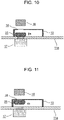
FIG. 11 is an explanatory cross-sectional view of the area around the cover opening and closing device with the cover repelling the magnet and one of the elastic forces being reduced in the third exemplary embodiment; -
FIG. 12 is an explanatory cross-sectional view of an area around a cover opening and closing device with an object being shielded by a cover in a fourth exemplary embodiment; and -
FIG. 13 is an explanatory cross-sectional view of the area around the cover opening and closing device with the cover being magnetically deformed and passing through a narrowed position in the fourth exemplary embodiment. - Exemplary embodiments will be described below in detail with reference to the drawings as appropriate. However, descriptions more detailed than necessary may be omitted. For example, detailed descriptions of already well-known matters, and duplicated descriptions of substantially identical configurations may be omitted. These omissions are intended to avoid excessive redundancy in the following description, and to facilitate understanding of those skilled in the art. Note that the accompanying drawings and the following description are provided for those skilled in the art to fully understand the present disclosure, and are not intended to limit the subject matter recited in the appended claims.
- Moreover, in the following exemplary embodiments, a description will be given of an example in which a cover opening and closing device is mounted on a monitor (which is an example of a display apparatus) to be attached to a passenger seat of an aircraft. However, the present disclosure is not limited to this example.
- A first exemplary embodiment will be described below with reference to
FIGS. 1 to 6 . -
FIG. 1 is an external view of a monitor having a cover opening and closing device built therein according to the first exemplary embodiment.Monitor 11 includesframe 11a that is an outer portion ofmonitor 11 anddisplay 11b that is a portion where an image is displayed.Frame 11a is an example of a housing of the cover opening and closing device and thus an example of a housing ofmonitor 11.Frame 11a includestransmission part 12.Frame 11a includes a camera mounted therein. The camera can capture an image throughtransmission part 12. -
Frame 11a is made of a material, such as resin, aluminum, or glass, which does not have a magnetic force by itself and can transmit a magnetic force. -
Transmission part 12 is a transparent circular member. For example,transmission part 12 is made of transparent resin or transparent glass. Note that in the present exemplary embodiment,transmission part 12 is a transparent member and is formed integrally withframe 11a.Frame 11a is a portion that is subjected to decoration, such as coating, which does not allow light to pass therethrough.Transmission part 12 is a portion that is not subjected to decoration, that is, a transparent portion. -
FIG. 2 is a cross-sectional view of an area around the camera and the cover opening and closing device according to the first exemplary embodiment.Frame 11a includescamera 16 that is an example of an object. The cover opening and closing device according to the present exemplary embodiment includesguide 13 disposed betweenframe 11a andcamera 16 and fixed toframe 11a, and cover 15 movable withinguide 13. That is,guide 13 accommodatescover 15. More specifically,cover 15 is accommodated in a space betweenguide 13 andframe 11a. -
Guide 13 has opening 14, through whichcamera 16 can capture an image, at a position betweencamera 16 andtransmission part 12. In addition, in order not to affect an operation ofcover 15,guide 13 is made of a material, such as resin, which does not have a magnetic force by itself and can transmit a magnetic force.Cover 15 can move, alongguide 13, between a first position where cover 15overlaps camera 16 andshields camera 16 as illustrated inFIG. 3 and a second position wherecover 15 does not shieldcamera 16 as illustrated inFIG. 4 .FIG. 3 andFIG. 4 will be described later.Guide 13 has a lateral dimension more than twice a lateral dimension ofcover 15 such thatcover 15 moved to the second position does not shieldcamera 16. A lateral direction ofguide 13 corresponds to a longitudinal direction ofguide 13, for example. A lateral direction ofcover 15 corresponds to a longitudinal direction ofcover 15, for example. In the first exemplary embodiment,guide 13 has a rectangular cross section, with its long side directed laterally, betweentransmission part 12 and opening 14. -
Opening 14 is disposed on an optical axis ofcamera 16 and has a dimension such that a field of view ofcamera 16 is not shielded. For example, opening 14 is formed by hollowing out a portion ofguide 13, or is embedded with transparent resin or transparent glass that allows light to pass through. In the first exemplary embodiment, opening 14 is formed by hollowing outguide 13 into a cylindrical shape so as to have a diameter the same as that oftransmission part 12. -
Cover 15 is a member including a magnetically attractive material or a magnetically repulsive material. Examples of the magnetically attractive material include an iron-based material and a heteropolar magnet. An example of the magnetically repulsive material includes a homopolar magnet. In this case, one surface of each ofmagnet 17 and cover 15 is a monopolar magnet. For attraction, cover 15 is disposed with its pole different from that ofmagnet 17 being directed to a surface offrame 11a. For repulsion, cover 15 is disposed with its pole the same as that ofmagnet 17 being directed to the surface offrame 11a.Cover 15 has a thickness less than a depthwise dimension ofguide 13. A depth direction ofguide 13 corresponds to a normal direction offrame 11a or a normal direction of a display surface ofdisplay 11b.Cover 15 has a heightwise dimension and a lateral dimension that are less than a heightwise dimension ofguide 13, but are equal to or greater than a heightwise dimension oftransmission part 12. A height direction ofcover 15 corresponds to a height direction ofmonitor 11. The lateral direction ofcover 15 corresponds to a lateral direction ofmonitor 11, for example, a longitudinal direction ofmonitor 11. In the first exemplary embodiment, cover 15 has a cylindrical shape having a diameter greater than that oftransmission part 12. Under no magnetic force applied to cover 15, cover 15 is in contact, on its lower surface, withguide 13 by its own weight. At this time, cover 15 is in contact, at a certain point, side, or surface somewhere, withguide 13 orframe 11a, due to a gravitational force applied to cover 15 or inclination ofcover 15, in a depth direction or in the lateral direction of cover 15 (for example, the longitudinal direction of cover 15). - Next, a moving position of
cover 15 will be described with reference toFIGS. 3 and4 .FIG. 3 is an explanatory enlarged view of an area around the cover opening and closing device with the camera being shielded by the cover according to the first exemplary embodiment.FIG. 4 is an explanatory enlarged view of the area around the cover opening and closing device with the camera not being shielded by the cover according to the first exemplary embodiment. - As illustrated in
FIG. 3 , cover 15 shieldingcamera 16 andtransmission part 12 are set in the same position. As illustrated inFIG. 3 , whencover 15 is positioned so as to shieldcamera 16,camera 16 cannot capture an image of a subject at aposition facing monitor 11. - On the other hand, as illustrated in
FIG. 4 , whencover 15 is positioned so as not to shieldcamera 16,camera 16 can capture, throughopening 14 andtransmission part 12, an image of the subject at theposition facing monitor 11. - An operation of the cover opening and closing device configured as described above will be described with reference to
FIGS. 5 and6 .FIG. 5 is an explanatory cross-sectional view of the area around the cover opening and closing device with the cover attracted to the magnet being moved to the position where the cover shields the camera in the first exemplary embodiment.FIG. 6 is an explanatory cross-sectional view of the area around the cover opening and closing device with the cover being moved by the magnet to the position where the cover does not shield the camera in the first exemplary embodiment. -
Cover 15 includes a magnetically attractive material. Whenmagnet 17 is brought close to the surface offrame 11a, cover 15 is attracted to the magnet and brought close toframe 11a. In this state,magnet 17 is moved in the lateral direction, and thereby, cover 15 can be moved under an attractive force ofmagnet 17 to the second position wherecover 15 does not shieldcamera 16 as illustrated inFIG. 6 . Here, whenmagnet 17 is brought away from the surface offrame 11a, in a case where the lower surface ofcover 15 is in contact withguide 13, cover 15 rests onguide 13, and in a case wherecover 15 is floating fromguide 13, cover 15 drops onto and rests onguide 13. Whencover 15 at the second position wherecover 15 does not shieldcamera 16 as illustrated inFIG. 6 is to be moved to the first position wherecover 15shields camera 16 as illustrated inFIG. 5 ,magnet 17 needs only to be brought close to the surface offrame 11a and oppositely moved from the second position. - In a case where
cover 15 includes a magnetically repulsive material, whenmagnet 17 is brought close to the surface offrame 11a, cover 15 repels the magnet and moves away fromframe 11a. In this state,magnet 17 is positionally moved in the lateral direction (for example, the longitudinal direction of cover 15), and thereby, cover 15 can be moved under a repulsive force ofmagnet 17 to the second position wherecover 15 does not shieldcamera 16 as illustrated inFIG. 6 . Here, whenmagnet 17 is brought away from the surface offrame 11a, in the case where the lower surface ofcover 15 is in contact withguide 13, cover 15 rests onguide 13, and in the case wherecover 15 is floating fromguide 13, cover 15 drops onto and rests onguide 13. Whencover 15 at the second position wherecover 15 does not shieldcamera 16 is to be moved to the first position wherecover 15shields camera 16, as in the case wherecover 15 is attracted tomagnet 17,magnet 17 needs only to be brought close to the surface offrame 11a and moved. As described above, guide 13 is configured to allowmagnet 17 to movecover 15 between the first position wherecover 15shields camera 16 and the second position wherecover 15 does not shieldcamera 16. - As described above, in the present exemplary embodiment, monitor 11 includes
camera 16 and cover 15 that is magnetically movable. - This prevents cover 15 from being directly touched from the outside of
monitor 11. Thus, for example, an airline that provides monitor 11 can prevent, for example, apassenger using monitor 11 from moving the position ofcover 15. Furthermore, when the cover needs to be opened and closed, cover 15 can be moved from the outside ofmonitor 11 by using a magnet. - A second exemplary embodiment will be described below with reference to
FIGS. 7 and8 . -
FIG. 7 is an explanatory enlarged view of an area around a cover opening and closing device with an object being shielded by a cover according to the second exemplary embodiment.FIG. 8 is an explanatory enlarged view of the area around the cover opening and closing device with the object not being shielded by the cover according to the second exemplary embodiment.Guide 23 is basically the same asguide 13 according to the first exemplary embodiment in terms of a material and a relationship between the guide and each oftransmission part 12 andopening 14. However, guide 23 has a third position between the first position wherecover 15shields camera 16 and the second position wherecover 15 does not shieldcamera 16, the third position being a position whereguide 23 has, on its lower side, a freely selected portion raised likeprotrusion 28 in a direction opposite to a direction of gravitational force applied to monitor 11. That is,protrusion 28 protrudes in vertical direction D1 (seeFIG. 7 ).Protrusion 28 can preventcover 15 under no magnetic force applied thereto from moving between the first position wherecover 15shields camera 16 and the second position wherecover 15 does not shieldcamera 16.Cover 15 is movable alongguide 23. - An operation of the cover opening and closing device configured as described above will be described below. Since the freely selected portion on the lower side of
guide 23 is raised likeprotrusion 28 in the direction opposite to the direction of gravitational force applied to monitor 11, cover 15 is guided by its own weight to either the first position wherecover 15shields camera 16 as illustrated inFIG. 7 or the second position wherecover 15 does not shieldcamera 16 as illustrated inFIG. 8 , without stopping at any position, such as the third position, between the first position and the second position. In order to movecover 15 between the first position and the second position, similarly to the first exemplary embodiment,magnet 17 is brought close to the surface offrame 11a to causecover 15 to attract or repel and to be moved. - As described above, in the present exemplary embodiment, with provision of
protrusion 28 inguide 23, cover 15 spontaneously moves by its own weight to either the first position wherecover 15shields camera 16 or the second position wherecover 15 does not shieldcamera 16. As long ascover 15 is not moved by usingmagnet 17, it is possible to reduce an unintended positional change ofcover 15, which is caused by vibrations or the like, between the first position wherecover 15shields camera 16 and the second position wherecover 15 does not shieldcamera 16. - This makes it possible to reduce the movement of
cover 15 beyond the third position, for example, even whencover 15 undergoes vibrations transmitted from an aircraft, and involves changes in the direction of gravitational force due to a tilt of the aircraft. - A third exemplary embodiment will be described below with reference to
FIGS. 9 to 11 . -
FIG. 9 is an explanatory cross-sectional view of an area around a cover opening and closing device with a cover having elastic forces acting in both directions (two-way directions) of a depth according to the third exemplary embodiment.Cover 35 has a depthwise natural length greater than a width ofguide 13.Cover 35 under no magnetic force applied thereto has repulsive elastic forces acting in both direction a and direction b. For example, cover 35 integrally includes a plurality of different components as a configuration in which a magnetically attractive portion or a magnetically repulsive portion containing iron powder or the like is provided at a periphery (edge) of an elastically deformable portion made of rubber or resin. Alternatively, for example, cover 35 includes one component such as an elastic body including rubber or resin blended with iron powder. Then, cover 35 is deformed when being attracted to or repelled by a magnetic force. The heightwise dimension and the lateral dimension ofcover 35 are less than the heightwise dimension ofguide 13, but are equal to or greater than the dimension oftransmission part 12. In the third exemplary embodiment, cover 35 has a cylindrical shape having a diameter greater than that oftransmission part 12.Cover 35 is movable alongguide 13. - An operation of the cover opening and closing device configured as described above will be described with reference to
FIGS. 9 to 11 .FIG. 10 is an explanatory cross-sectional view of the area around the cover opening and closing device with the cover being attracted to a magnet and one of the elastic forces being reduced in the third exemplary embodiment.FIG. 11 is an explanatory cross-sectional view of the area around the cover opening and closing device with the cover repelling the magnet and one of the elastic forces being reduced in the third exemplary embodiment. As illustrated inFIG. 9 , cover 35 under no magnetic force thereto is fixed by repulsive forces acting in both direction a and direction b of the depth and frictional forces acting on both surfaces ofcover 35. As illustrated inFIG. 10 , whencover 35 is attracted tomagnet 17, cover 35 is deformed in direction a and the repulsive force acting in direction b is reduced. Thus, cover 35 is no longer fixed. On the other hand, as illustrated inFIG. 11 , whencover 35 is repelled bymagnet 17, cover 35 is deformed in direction b and the repulsive force acting in direction a is reduced. Thus, cover 35 is no longer fixed. With one repulsive force being reduced as illustrated inFIGS. 10 and 11 , cover 35 can be moved together with lateral movement ofmagnet 17. Then, whenmagnet 17 is brought away from the surface offrame 11a, the deformation ofcover 35 is restored, and the repulsive forces act on both direction a and direction b again, resulting in fixing ofcover 35. - As described above, in the present exemplary embodiment, cover 35 is positionally fixed by the repulsive forces in the depth direction, and restrained from being positionally changed as long as
cover 35 is not moved by usingmagnet 17. - This makes it possible to restrain the movement of
cover 35, for example, even whencover 35 undergoes vibrations transmitted from an aircraft, and involves changes in the direction of gravitational force due to a tilt of the aircraft. - A fourth exemplary embodiment will be described below with reference to
FIGS. 12 and 13 . -
FIG. 12 is an explanatory cross-sectional view of an area around a cover opening and closing device with an object being shielded by a cover in the fourth exemplary embodiment.Guide 43 is basically the same asguide 13 according to the first exemplary embodiment in terms of a material and a relationship between the guide and each oftransmission part 12 andopening 14. However, guide 43 has a third position, at which guide 43 has narrowed width La in a depth of a freely selected portion, between a first position wherecover 45shields camera 16 and a second position wherecover 45 does not shieldcamera 16. At the third position, guide 43 has portions protruding from both sides thereof in the depth direction and thereby has the narrowed width. - For example, cover 45 integrally includes a plurality of different components as a configuration in which a magnetically attractive portion or a magnetically repulsive portion containing iron powder or the like is provided at a periphery (edge) of an elastically deformable portion made of rubber or resin. Alternatively, for example, cover 45 includes one component such as an elastic body including rubber or resin blended with iron powder.
Cover 45 under no magnetic force applied thereto has a natural length having width L1 greater than width La at the third position ofguide 43. However, whencover 45 is deformed by a magnetic force as illustrated inFIG. 13 to be described later, cover 45 has a length having width L2 less than width La at the third position ofguide 43.Cover 45 having a thickness across width L1 cannot pass through the third position ofguide 43 because width L1 is greater than width La.Cover 45 deformed to a shape having width L2 can pass through the third position because width L2 is less than width La. The heightwise dimension and the lateral dimension ofcover 45 are less than the heightwise dimension ofguide 43, but are equal to or greater than the dimension oftransmission part 12. In the fourth exemplary embodiment, cover 45 has a cylindrical shape having a diameter greater than that oftransmission part 12.Cover 45 is movable alongguide 43. As described above, guide 43 has a clearance at the third position. The clearance has a predetermined length (width La) in depth direction D2 (seeFIG. 12 ) offrame 11a. - An operation of the cover opening and closing device configured as described above will be described with reference to
FIGS. 12 and 13. FIG. 13 is an explanatory cross-sectional view of the area around the cover opening and closing device with the cover being magnetically deformed and passing through the narrowed position in the fourth exemplary embodiment. Whencover 45 is at the first position wherecover 45shields camera 16 as illustrated inFIG. 12 , cover 45 under no magnetic force applied thereto is not subjected to a force by which cover 45 is fixed. Therefore, whencover 45 undergoes vibrations transmitted from an aircraft, and involves changes in the direction of gravitational force due to a tilt of the aircraft, cover 45 freely moves. However, since width L1 ofcover 45 is greater than width La at the third position ofguide 43, cover 45 does not move to the second position beyond the third position. The same holds true for the case ofcover 45 being at the second position, and cover 45 does not move to the first position from the second position beyond the third position. - However, as illustrated in
FIG. 13 , whenmagnet 17 applies a magnetic force to cover 45, cover 45 is deformed by an attractive force or a repulsive force to a shape having width L2 less than width La of the narrowed portion ofguide 43. At this time, cover 45 passes through the third position ofguide 43 to be switched between the first position wherecover 45shields camera 16 and the second position wherecover 45 does not shieldcamera 16. - As described above, in the present exemplary embodiment, since depthwise thickness L1 of
cover 45 is greater than width La of the narrowed portion ofguide 43, cover 45 can be restrained from being positionally changed beyond the third position as long ascover 45 is not moved by usingmagnet 17. - This makes it possible to restrain the movement of
cover 45 between the first position and the second position beyond the third position, for example, even whencover 45 undergoes vibrations transmitted from an aircraft, and involves changes in the direction of gravitational force due to a tilt of the aircraft. - The first to fourth exemplary embodiments have been described above as examples of the techniques disclosed in the present application. However, the techniques of the present disclosure are not limited to the first to fourth exemplary embodiments, and can also be applied to exemplary embodiments in which modifications, replacements, additions, omissions, and the like are made. In addition, new exemplary embodiments can be made by combining the constituent elements described in the first to fourth exemplary embodiments. In particular, the second exemplary embodiment may be combined with the third exemplary embodiment and the fourth exemplary embodiment.
- Other exemplary embodiments will be described below as an example.
- Although the shapes of
transmission part 12, guide 13, opening 14, and cover 15 are defined in the first exemplary embodiment, each shape is an example. As long as the similar effect can be obtained, these components may have, for example, a shape having an uneven height and an uneven thickness, and a shape having a combination of curved surface shapes. - In the third exemplary embodiment described above, cover 35 has the repulsive forces in the depth direction. However, the shape is an example. The direction in which the repulsive forces act may be, for example, the height direction instead of the depth direction of
guide 13. For example, an elastic body has, for example in its height direction, an upper portion including a magnetically attractive material or a magnetically repulsive material, and is attracted to or repelled bymagnet 17 and then moved in the height direction. This causes heightwise deformation ofcover 35, and allowscover 35 to be positionally moved by being moved in the lateral direction while keeping the deformed state. When the magnet is brought away fromcover 35 after the movement ofcover 35, the heightwise deformation ofcover 35 is restored, and the elastic forces act in both directions of a height. Thus, the movement ofcover 35 can be restrained. - In the fourth exemplary embodiment described above, guide 43 has portions protruding from both sides thereof in the depth direction and thereby has thickness La. However, guide 43 has only to have thickness La less than thickness L1 of
cover 45 in a freely selected portion. Therefore, only one of surfaces ofguide 43 in the depth direction may have a protruding portion, and the other may be flat. - In the fourth exemplary embodiment described above, guide 43 has the narrowed width in the depth of the freely selected portion. However, the shape is an example.
Guide 43 may have the narrowed width, for example, in the height direction instead of the depth direction. For example, an elastic body has, for example in its height direction, an upper portion including a magnetically attractive material or a magnetically repulsive material, and is attracted to or repelled bymagnet 17 and then moved in the height direction. This causes heightwise deformation ofcover 45, and allowscover 45 to be positionally moved by being moved in the lateral direction while keeping the deformed state. When the magnet is brought away fromcover 45 after the movement ofcover 45, the heightwise deformation ofcover 45 is restored, and the height ofcover 45 becomes greater than the height ofcover 45 at the third position. Thus, cover 45 can be restrained from being positionally changed beyond the third position. - In the first to fourth exemplary embodiments described above as an example, monitor 11 includes
transmission part 12. However,transmission part 12 may be an opening provided inmonitor 11. - In the first to fourth exemplary embodiments,
transmission part 12 is made of a transparent material. However,transmission part 12 may be made of an opaque material as long as the camera is operable. - In the first to fourth exemplary embodiments,
camera 16 is positioned atframe 11a ofmonitor 11. However,camera 16 may be disposed indisplay 11b. - In the first to fourth exemplary embodiments,
frame 11a and the guide are made of resin having no magnetic force. However,frame 11a and the guide may each have a magnetic force as long as their magnetic forces are weaker than the magnetic force ofmagnet 17 for operating the cover from the outside offrame 11a and the cover can be operated. - In the first to fourth exemplary embodiments, the moving direction of the cover is the lateral direction. However, the moving direction of the cover may be a direction different from the lateral direction, such as an oblique direction, a lengthwise direction, and a circumferential direction.
- In the first to fourth exemplary embodiments described above,
camera 16 is built inmonitor 11. However,camera 16 may be provided in the outside ofmonitor 11 so as to operate as a module of the camera by itself rather than being built inmonitor 11. - In the first to fourth exemplary embodiments described above, the object is
camera 16. However, the object may be any object that needs to be switched between an open state and a closed state. For example, the object may be a sensor configured to detect a state in front ofmonitor 11, for example, brightness, a distance from the sensor to a close object, a temperature, or the like. For example, the object may be a light source itself or illumination that propagates light from a distant place by refraction or reflection. In addition, the surface of the object and the portion of opening 14 ofguide 13 may be decorated with a design or coloring. - In the first to fourth exemplary embodiments, the monitor to be attached to the passenger seat of the aircraft has been described as an example. However, the passenger seat of the aircraft is an example as an attachment destination. The monitor may be attached, for example, to a wall and a ceiling other than the passenger seat. In addition, although an aircraft has been described as an example, another movable body may be possible. For example, the movable body may be a flying body other than an aircraft, a traveling vehicle, and a movable body that can be carried by a user.
- Note that, the above exemplary embodiments are to exemplify the techniques in the present disclosure, and therefore, various modifications, replacements, additions, omissions, and the like can be made in the scope of the appended claims or in an equivalent scope thereof.
- The present disclosure can be applied to a cover opening and closing device in which a cover can be opened and closed without being touched. Specifically, the present disclosure can be applied to, for example, a monitor itself or a monitor having, at its periphery, a camera, a sensor, decoration, and a function of illuminating.
Claims (11)
- A cover opening and closing device for shielding an object, the cover opening and closing device comprising:a cover attractable to or repellable by a magnet;a guide accommodating the cover; anda housing covering the guide,whereinthe cover is accommodated in a space between the guide and the housing, andthe guide allows the cover to be moved, by the magnet outside the space, between a first position where the cover shields the object and a second position where the cover does not shield the object.
- The cover opening and closing device according to claim 1, whereinthe guide includes a protrusion between the first position and the second position, andthe protrusion protrudes vertically.
- The cover opening and closing device according to claim 1, whereinthe cover has an elastic force that presses the cover against both the guide and the housing, andwhen the magnet is brought close to the cover, the cover is deformed and reduces the elastic force.
- The cover opening and closing device according to claim 1, wherein the guide has a clearance between the first position and the second position, the clearance having a predetermined length in a depth direction of the housing,the cover has a first length in the depth direction,when the magnet is brought close to the cover, the cover is deformed and changes a length of the cover from the first length to a second length, andthe predetermined length of the clearance is less than the first length and greater than the second length.
- The cover opening and closing device according to any one of claims 2 to 4, wherein the object is a camera configured to capture an image in a direction toward a front surface of the housing.
- The cover opening and closing device according to any one of claims 2 to 4, wherein the object is a sensor configured to detect a state in front of the housing.
- The cover opening and closing device according to any one of claims 2 to 4, wherein the object has a decorated surface.
- The cover opening and closing device according to any one of claims 2 to 4, wherein the object is a light source.
- The cover opening and closing device according to any one of claims 1 to 8, wherein the housing is a part of a display apparatus.
- The cover opening and closing device according to any one of claims 1 to 9, wherein the housing is installed in a movable body.
- The cover opening and closing device according to any one of claims 1 to 10, whereinthe guide has an opening,the housing includes a transmission part, andwhen the cover is at the first position, the object, the opening, the cover, and the transmission part are aligned.
Applications Claiming Priority (1)
| Application Number | Priority Date | Filing Date | Title |
|---|---|---|---|
| JP2021109480A JP2023006733A (en) | 2021-06-30 | 2021-06-30 | Cover opening/closing device |
Publications (2)
| Publication Number | Publication Date |
|---|---|
| EP4113207A1 true EP4113207A1 (en) | 2023-01-04 |
| EP4113207B1 EP4113207B1 (en) | 2025-08-20 |
Family
ID=79730370
Family Applications (1)
| Application Number | Title | Priority Date | Filing Date |
|---|---|---|---|
| EP22151913.5A Active EP4113207B1 (en) | 2021-06-30 | 2022-01-18 | Cover opening and closing device, preferably for a camera module. |
Country Status (3)
| Country | Link |
|---|---|
| US (1) | US11822209B2 (en) |
| EP (1) | EP4113207B1 (en) |
| JP (1) | JP2023006733A (en) |
Citations (4)
| Publication number | Priority date | Publication date | Assignee | Title |
|---|---|---|---|---|
| EP1833241A1 (en) * | 2006-03-10 | 2007-09-12 | Samsung Electro-Mechanics Co., Ltd | Lens protecting apparatus for cellular phone camera |
| US20110115924A1 (en) * | 2009-11-13 | 2011-05-19 | Primax Electronics Ltd. | Image pickup device |
| JP2019008037A (en) | 2017-06-21 | 2019-01-17 | 京セラ株式会社 | Electronics |
| WO2019156683A1 (en) * | 2018-02-12 | 2019-08-15 | Hewlett-Packard Development Company, L.P. | View shutters with slider magnets |
Family Cites Families (5)
| Publication number | Priority date | Publication date | Assignee | Title |
|---|---|---|---|---|
| JP4177976B2 (en) | 2001-09-13 | 2008-11-05 | 富士フイルム株式会社 | camera |
| EP3548967A4 (en) * | 2017-04-10 | 2020-07-22 | Hewlett-Packard Development Company, L.P. | Ferromagnetic covers |
| WO2019022727A1 (en) * | 2017-07-26 | 2019-01-31 | Hewlett-Packard Development Company, L.P. | Swivel covers |
| KR102629415B1 (en) * | 2018-08-29 | 2024-01-26 | 삼성전자주식회사 | An electronic device including a camera security cover |
| US11422435B1 (en) * | 2021-06-17 | 2022-08-23 | Microsoft Technology Licensing, Llc | Camera privacy cover |
-
2021
- 2021-06-30 JP JP2021109480A patent/JP2023006733A/en active Pending
- 2021-12-17 US US17/554,223 patent/US11822209B2/en active Active
-
2022
- 2022-01-18 EP EP22151913.5A patent/EP4113207B1/en active Active
Patent Citations (4)
| Publication number | Priority date | Publication date | Assignee | Title |
|---|---|---|---|---|
| EP1833241A1 (en) * | 2006-03-10 | 2007-09-12 | Samsung Electro-Mechanics Co., Ltd | Lens protecting apparatus for cellular phone camera |
| US20110115924A1 (en) * | 2009-11-13 | 2011-05-19 | Primax Electronics Ltd. | Image pickup device |
| JP2019008037A (en) | 2017-06-21 | 2019-01-17 | 京セラ株式会社 | Electronics |
| WO2019156683A1 (en) * | 2018-02-12 | 2019-08-15 | Hewlett-Packard Development Company, L.P. | View shutters with slider magnets |
Also Published As
| Publication number | Publication date |
|---|---|
| EP4113207B1 (en) | 2025-08-20 |
| JP2023006733A (en) | 2023-01-18 |
| US11822209B2 (en) | 2023-11-21 |
| US20230004069A1 (en) | 2023-01-05 |
Similar Documents
| Publication | Publication Date | Title |
|---|---|---|
| US11448199B2 (en) | SMA actuator assembly | |
| US11685505B2 (en) | Window for an aircraft and display for aircraft window | |
| US9726895B2 (en) | Wearable display device having a sliding structure | |
| US11112612B2 (en) | Hinge mechanism and head-mounted display including this hinge mechanism | |
| US20240160027A1 (en) | Optical device for enhancing resolution of an image or for reducing speckle noise | |
| US10345581B2 (en) | Display device and head mounted image display apparatus | |
| JP2019535062A (en) | Operation unit for equipment, especially for in-vehicle equipment | |
| EP4113207A1 (en) | Cover opening and closing device, preferably for a camera module. | |
| JP2022553355A (en) | electronic device | |
| KR900004231A (en) | Lunch box type electronics | |
| US10312030B2 (en) | Illuminated keypad module with limited light leakage | |
| WO2022250393A1 (en) | Actuator applied with multi-surface protruding damper | |
| CN110113465A (en) | Housing unit and electronic equipment | |
| EP4092506A1 (en) | Electronic device with camera anti-peeping structure | |
| KR20230033017A (en) | Anti-reflection camera housing system | |
| CN216622842U (en) | Head-mounted device | |
| WO2021008012A1 (en) | Wearable device having flexible screen | |
| US20120281288A1 (en) | Control device | |
| CN209821508U (en) | Freely adjustable HUD | |
| CN210469480U (en) | Camera shielding device, front frame and front frame assembly | |
| CN220440752U (en) | Mobile phone shell | |
| JP2005039745A (en) | Optical remote control receiver | |
| US20240184329A1 (en) | Device With Light-Shielding Structure | |
| CN115808787B (en) | Head-mounted devices | |
| CN115808789B (en) | Frame, wear support and head-mounted device |
Legal Events
| Date | Code | Title | Description |
|---|---|---|---|
| PUAI | Public reference made under article 153(3) epc to a published international application that has entered the european phase |
Free format text: ORIGINAL CODE: 0009012 |
|
| STAA | Information on the status of an ep patent application or granted ep patent |
Free format text: STATUS: THE APPLICATION HAS BEEN PUBLISHED |
|
| AK | Designated contracting states |
Kind code of ref document: A1 Designated state(s): AL AT BE BG CH CY CZ DE DK EE ES FI FR GB GR HR HU IE IS IT LI LT LU LV MC MK MT NL NO PL PT RO RS SE SI SK SM TR |
|
| STAA | Information on the status of an ep patent application or granted ep patent |
Free format text: STATUS: REQUEST FOR EXAMINATION WAS MADE |
|
| 17P | Request for examination filed |
Effective date: 20230704 |
|
| RBV | Designated contracting states (corrected) |
Designated state(s): AL AT BE BG CH CY CZ DE DK EE ES FI FR GB GR HR HU IE IS IT LI LT LU LV MC MK MT NL NO PL PT RO RS SE SI SK SM TR |
|
| GRAP | Despatch of communication of intention to grant a patent |
Free format text: ORIGINAL CODE: EPIDOSNIGR1 |
|
| STAA | Information on the status of an ep patent application or granted ep patent |
Free format text: STATUS: GRANT OF PATENT IS INTENDED |
|
| RIC1 | Information provided on ipc code assigned before grant |
Ipc: B64D 11/00 20060101ALN20250220BHEP Ipc: G06F 1/16 20060101ALN20250220BHEP Ipc: G03B 11/04 20210101AFI20250220BHEP |
|
| INTG | Intention to grant announced |
Effective date: 20250310 |
|
| GRAS | Grant fee paid |
Free format text: ORIGINAL CODE: EPIDOSNIGR3 |
|
| GRAA | (expected) grant |
Free format text: ORIGINAL CODE: 0009210 |
|
| STAA | Information on the status of an ep patent application or granted ep patent |
Free format text: STATUS: THE PATENT HAS BEEN GRANTED |
|
| AK | Designated contracting states |
Kind code of ref document: B1 Designated state(s): AL AT BE BG CH CY CZ DE DK EE ES FI FR GB GR HR HU IE IS IT LI LT LU LV MC MK MT NL NO PL PT RO RS SE SI SK SM TR |
|
| REG | Reference to a national code |
Ref country code: GB Ref legal event code: FG4D |
|
| REG | Reference to a national code |
Ref country code: CH Ref legal event code: EP |
|
| REG | Reference to a national code |
Ref country code: DE Ref legal event code: R096 Ref document number: 602022019625 Country of ref document: DE |
|
| REG | Reference to a national code |
Ref country code: IE Ref legal event code: FG4D |
|
| REG | Reference to a national code |
Ref country code: NL Ref legal event code: MP Effective date: 20250820 |
|
| PG25 | Lapsed in a contracting state [announced via postgrant information from national office to epo] |
Ref country code: IS Free format text: LAPSE BECAUSE OF FAILURE TO SUBMIT A TRANSLATION OF THE DESCRIPTION OR TO PAY THE FEE WITHIN THE PRESCRIBED TIME-LIMIT Effective date: 20251220 |
|
| PG25 | Lapsed in a contracting state [announced via postgrant information from national office to epo] |
Ref country code: NO Free format text: LAPSE BECAUSE OF FAILURE TO SUBMIT A TRANSLATION OF THE DESCRIPTION OR TO PAY THE FEE WITHIN THE PRESCRIBED TIME-LIMIT Effective date: 20251120 |
|
| REG | Reference to a national code |
Ref country code: LT Ref legal event code: MG9D |
|
| PG25 | Lapsed in a contracting state [announced via postgrant information from national office to epo] |
Ref country code: PT Free format text: LAPSE BECAUSE OF FAILURE TO SUBMIT A TRANSLATION OF THE DESCRIPTION OR TO PAY THE FEE WITHIN THE PRESCRIBED TIME-LIMIT Effective date: 20251222 |
|
| PG25 | Lapsed in a contracting state [announced via postgrant information from national office to epo] |
Ref country code: FI Free format text: LAPSE BECAUSE OF FAILURE TO SUBMIT A TRANSLATION OF THE DESCRIPTION OR TO PAY THE FEE WITHIN THE PRESCRIBED TIME-LIMIT Effective date: 20250820 |
|
| PG25 | Lapsed in a contracting state [announced via postgrant information from national office to epo] |
Ref country code: NL Free format text: LAPSE BECAUSE OF FAILURE TO SUBMIT A TRANSLATION OF THE DESCRIPTION OR TO PAY THE FEE WITHIN THE PRESCRIBED TIME-LIMIT Effective date: 20250820 Ref country code: HR Free format text: LAPSE BECAUSE OF FAILURE TO SUBMIT A TRANSLATION OF THE DESCRIPTION OR TO PAY THE FEE WITHIN THE PRESCRIBED TIME-LIMIT Effective date: 20250820 |
|
| PG25 | Lapsed in a contracting state [announced via postgrant information from national office to epo] |
Ref country code: GR Free format text: LAPSE BECAUSE OF FAILURE TO SUBMIT A TRANSLATION OF THE DESCRIPTION OR TO PAY THE FEE WITHIN THE PRESCRIBED TIME-LIMIT Effective date: 20251121 |
|
| PG25 | Lapsed in a contracting state [announced via postgrant information from national office to epo] |
Ref country code: SE Free format text: LAPSE BECAUSE OF FAILURE TO SUBMIT A TRANSLATION OF THE DESCRIPTION OR TO PAY THE FEE WITHIN THE PRESCRIBED TIME-LIMIT Effective date: 20250820 |
|
| PG25 | Lapsed in a contracting state [announced via postgrant information from national office to epo] |
Ref country code: LV Free format text: LAPSE BECAUSE OF FAILURE TO SUBMIT A TRANSLATION OF THE DESCRIPTION OR TO PAY THE FEE WITHIN THE PRESCRIBED TIME-LIMIT Effective date: 20250820 |
|
| PG25 | Lapsed in a contracting state [announced via postgrant information from national office to epo] |
Ref country code: BG Free format text: LAPSE BECAUSE OF FAILURE TO SUBMIT A TRANSLATION OF THE DESCRIPTION OR TO PAY THE FEE WITHIN THE PRESCRIBED TIME-LIMIT Effective date: 20250820 Ref country code: PL Free format text: LAPSE BECAUSE OF FAILURE TO SUBMIT A TRANSLATION OF THE DESCRIPTION OR TO PAY THE FEE WITHIN THE PRESCRIBED TIME-LIMIT Effective date: 20250820 |
|
| PG25 | Lapsed in a contracting state [announced via postgrant information from national office to epo] |
Ref country code: RS Free format text: LAPSE BECAUSE OF FAILURE TO SUBMIT A TRANSLATION OF THE DESCRIPTION OR TO PAY THE FEE WITHIN THE PRESCRIBED TIME-LIMIT Effective date: 20251120 |
|
| PG25 | Lapsed in a contracting state [announced via postgrant information from national office to epo] |
Ref country code: ES Free format text: LAPSE BECAUSE OF FAILURE TO SUBMIT A TRANSLATION OF THE DESCRIPTION OR TO PAY THE FEE WITHIN THE PRESCRIBED TIME-LIMIT Effective date: 20250820 |
|
| REG | Reference to a national code |
Ref country code: AT Ref legal event code: MK05 Ref document number: 1827922 Country of ref document: AT Kind code of ref document: T Effective date: 20250820 |
|
| PG25 | Lapsed in a contracting state [announced via postgrant information from national office to epo] |
Ref country code: SM Free format text: LAPSE BECAUSE OF FAILURE TO SUBMIT A TRANSLATION OF THE DESCRIPTION OR TO PAY THE FEE WITHIN THE PRESCRIBED TIME-LIMIT Effective date: 20250820 |
|
| PGFP | Annual fee paid to national office [announced via postgrant information from national office to epo] |
Ref country code: GB Payment date: 20260123 Year of fee payment: 5 |
|
| PG25 | Lapsed in a contracting state [announced via postgrant information from national office to epo] |
Ref country code: DK Free format text: LAPSE BECAUSE OF FAILURE TO SUBMIT A TRANSLATION OF THE DESCRIPTION OR TO PAY THE FEE WITHIN THE PRESCRIBED TIME-LIMIT Effective date: 20250820 |
|
| PGFP | Annual fee paid to national office [announced via postgrant information from national office to epo] |
Ref country code: DE Payment date: 20260121 Year of fee payment: 5 |
|
| PG25 | Lapsed in a contracting state [announced via postgrant information from national office to epo] |
Ref country code: AT Free format text: LAPSE BECAUSE OF FAILURE TO SUBMIT A TRANSLATION OF THE DESCRIPTION OR TO PAY THE FEE WITHIN THE PRESCRIBED TIME-LIMIT Effective date: 20250820 |
|
| PG25 | Lapsed in a contracting state [announced via postgrant information from national office to epo] |
Ref country code: IT Free format text: LAPSE BECAUSE OF FAILURE TO SUBMIT A TRANSLATION OF THE DESCRIPTION OR TO PAY THE FEE WITHIN THE PRESCRIBED TIME-LIMIT Effective date: 20250820 |
|
| PGFP | Annual fee paid to national office [announced via postgrant information from national office to epo] |
Ref country code: FR Payment date: 20260123 Year of fee payment: 5 |
|
| PG25 | Lapsed in a contracting state [announced via postgrant information from national office to epo] |
Ref country code: CZ Free format text: LAPSE BECAUSE OF FAILURE TO SUBMIT A TRANSLATION OF THE DESCRIPTION OR TO PAY THE FEE WITHIN THE PRESCRIBED TIME-LIMIT Effective date: 20250820 |
|
| PG25 | Lapsed in a contracting state [announced via postgrant information from national office to epo] |
Ref country code: EE Free format text: LAPSE BECAUSE OF FAILURE TO SUBMIT A TRANSLATION OF THE DESCRIPTION OR TO PAY THE FEE WITHIN THE PRESCRIBED TIME-LIMIT Effective date: 20250820 Ref country code: SK Free format text: LAPSE BECAUSE OF FAILURE TO SUBMIT A TRANSLATION OF THE DESCRIPTION OR TO PAY THE FEE WITHIN THE PRESCRIBED TIME-LIMIT Effective date: 20250820 |